

Page 1

ZeroTurnRadiusMowers
Allmodels
LooseParts
Usethechartbelowtoverifythatallpartshavebeenshipped.
FormNo.3360-101RevA
SetupInstructions
ProcedureDescription
Deectorassembly
Rod1
7
8
9
Note:Determinetheleftandrightsidesofthemachinefromthenormaloperatingposition.
1
Spring
Cotterpin
Sidedischargebafe
Carriagebolt(5/16x3/4inch)
Hex-headbolt(5/16x3/4inch)
Locknut(5/16inch)
Holecoverdecal3
IgnitionKey1
Hosecoupling1
Operator’sManual
EngineOperator’sManual
OperatorTrainingMaterial
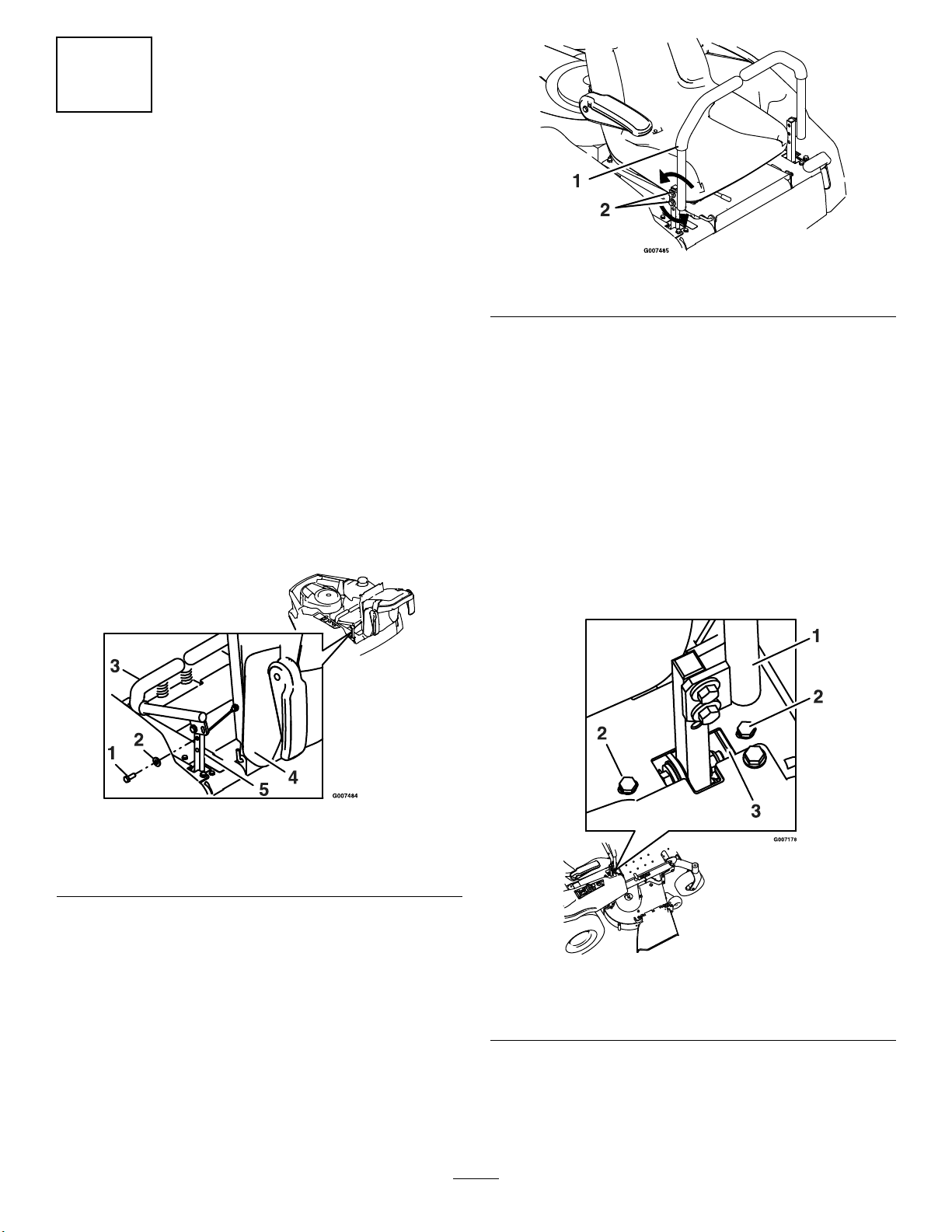
2.Tiltseatdownwardandalignlanyardtotheholein
3.Installboltandnut.Tightenboltandthenloosen
CheckingTirePressure
Qty.
1
1
1
1
2
2
4
1
1
1
thesideoftheseat(seeFigure1).
nut1/4-1/2turnsothatlanyardendrotatesfreely.
Verifythatlanyardisfreetorotateonbothendsso
thatitpullsstraightwhilesupportingtheseat..
NoPartsRequired
Use
Installthedischargedeector.
Converttosidedischarge(optional).
Completethesetup.
Procedure
1.Checkthetirepressureinthedrivetires.Proper
inationfordrivetiresis13psi(90kPa).
2.Adjustifnecessary.
2
FasteningtheSeat
NoPartsRequired
Procedure
1.Removethenutandboltfromthelooseendofthe
lanyard.
PrintedintheUSA.OriginalInstructions(EN)
AllRightsReserved
Page 2
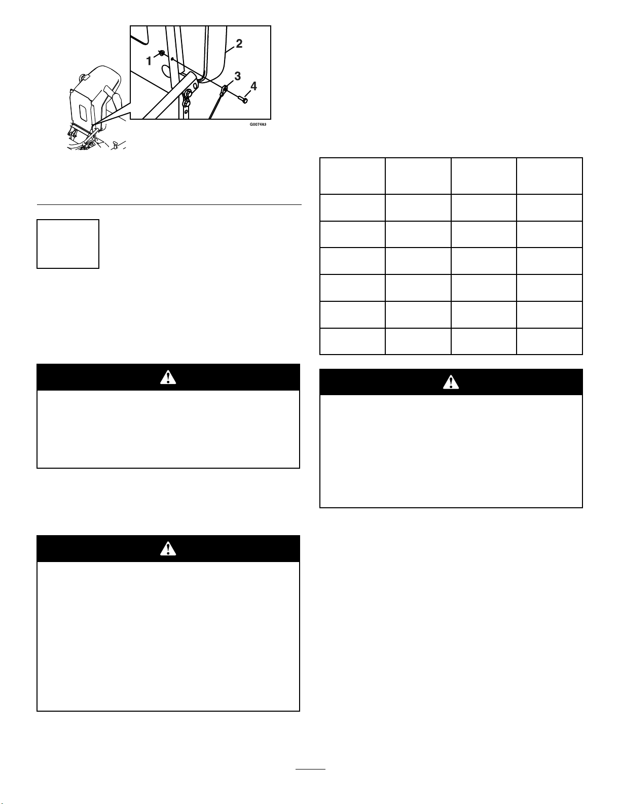
Figure1
1.Seatassembly3.5/16-18inchwhizlocknuts
2.Seattrackstuds
3
ServicingtheBattery
NoPartsRequired
Procedure
inthetablebelowandchargethebatteryforthe
recommendedtimeintervaltobringthechargeup
toafullchargeof12.6voltsorgreater.
Important:Makesurethenegativebattery
cablesaredisconnectedandthebatterycharger
usedforchargingthebatteryhasanoutputof
16voltsand7ampsorlesstoavoiddamaging
thebattery(seechartforrecommendedcharger
settings).
Voltage
Reading
12.6or
greater
12.4–12.6
12.2–12.4
12.0–12.2
11.7–12.0
11.7orless
Percent
Charge
100%16volts/7
75–100%16volts/7
50–75%16volts/7
25–50%14.4volts/4
0–25%14.4volts/4
0%14.4volts/2
Maximum
Charger
Settings
amps
amps
amps
amps
amps
amps
Charging
Interval
NoCharging
Required
30Minutes
1Hour
2Hours
3Hours
6Hoursor
More
Batteryposts,terminals,andrelatedaccessories
containleadandleadcompounds,chemicals
knowntotheStateofCaliforniatocausecancer
andreproductiveharm.Washhandsafter
handling.
Important:Themachineisshippedwithalled
leadacidbattery.
1.Tiltseatuptogainaccesstothebattery.
Chargingthebatterymayproduceexplosive
gasses.Batterygassescanexplodecausing
seriousinjury.
•Keepsparks,ames,orcigarettesawayfrom
battery.
•Ventilatewhenchargingorusingbatteryin
anenclosedspace.
•Makesureventingpathofbatteryisalways
openoncebatteryislledwithacid.
Iftheignitionisinthe“ON”positionthere
ispotentialforsparksandengagementof
components.Sparkscouldcauseanexplosion
ormovingpartscouldaccidentallyengage
causingpersonalinjury
Besureignitionswitchisinthe“OFF”position
beforechargingthebattery.
3.Connectthenegativebatterycables.
Note:Ifthepositivecableisalsodisconnected,
connectthepositive(red)cabletothepositive
batteryterminalrst,thenthenegative(black)cable
tothenegativebatteryterminal.Slipinsulatorboot
overthepositiveterminal.
Note:Iftimedoesnotpermitchargingthebattery,
orifchargingequipmentisnotavailable,connect
thenegativebatterycablesandrunthevehicle
continuouslyfor20to30minutestosufciently
chargethebattery.
2.Checkthevoltageofthebatterywithadigital
voltmeter.Locatethevoltagereadingofthebattery
2
Page 3
4
InstallingtheMotionControl
Levers
NoPartsRequired
Procedure
1.Removethebottom3/8x1inchboltandspring
discwasherfromthecontrolarmshaft.Loosenthe
upper3/8x1inchboltandspringdiscwasherinthe
controlleversothatthelevercanrotateFigure2.
2.Positiontheleversothebottomholealignswith
holeinthecontrolarmshaft.Installspringdisc
washerandbolt.
3.Repeatonoppositesideofunit.
Note:Therearetwoleverheightoptionsavailable.
Placetheleversinthetoptwoholestoincrease
heightofthelevers,orinthebottomtwoholesto
decreasetheheightofthelevers.
Figure3
1.Motioncontrollever2.Hardware
5.Iftheendsofthelevershitagainsteachother,
whileinthedriveposition(leversrotatedinasfaras
possible),makeadjustmentsbymovingthelevers
outwardstotheneutrallockpositionandcarefully
bendingthemoutward.Movethembacktothedrive
positionandcheckforclearance.Repeatifnecessary.
6.Ifthemachineturnsrightorleftwhenhandlesare
pushedforwardtogether,adjustthestoponthe
sideoppositethedirectionofturn(seeFigure4).
Loosenthescrewsthatholdthemotioncontrol
limiterstop.Movethestopbackuntiltheunitdrives
straight.Tightenthescrewstolockthestopinplace.
Readjusthandlesifnecessary.
Figure2
1.Bolt
2.Springdiscwasher5.Controlarmshaft
3.Motioncontrollever
4.Aligntheleversfront/rearposition.Withthelevers
intheneutralposition,loosenthehardwareand
adjusttheleversslidingand/ortiltingthelever(s)
forwardorbackwarduntilproperlyalignedand
tightenhardware(Figure3).
4.Seat
1.Controlarmshaft
2.Limiterstopscrews
3
Figure4
3.Adjuststop
Page 4

5
ServicingtheEngine
NoPartsRequired
Procedure
Engineisshippedwithoil;checkoillevelandif
necessarylltotheappropriatelevelwithoilasspecied
inEngineOwner’sManual.
Figure5
1.Engine2.Expansiontank
6
ServicingtheHydraulicOil
NoPartsRequired
Procedure
Themachineisshippedwithhydraulicoil.Verifylevel
onExpansionTank(seeFigure5).
1.Startengineanddrivethemachineforwardand
backwardforafewminutestoallowanyextraairto
purgeoutofthehydraulicsystem.
2.Stopengineandwaitforallmovingpartstostop.
Removekeyandengageparkingbrake.
3.CheckexpansiontankandifnecessaryaddMOBIL1
15W-50syntheticmotoroiltotheFULLCOLDline.
Note:Theproperamountofoilshouldhavebeen
addedatthefactory.Ifthereservoirisslightlyover
full,DoNotremoveuid.Thelevelwillgodown
oncealloftheairispurgedfromthesystem.
4.Replaceexpansiontankcapandtightenuntilsnug.
DoNotovertighten.
7
InstallingtheDischarge
Deector
Partsneededforthisprocedure:
1
Deectorassembly
1Rod
1
Spring
1
Cotterpin
Procedure
1.Installdischargedeector(Figure6).
4
Page 5

8
ConvertingtoSideDischarge
(optional)
Partsneededforthisprocedure:
1
Sidedischargebafe
2
Carriagebolt(5/16x3/4inch)
2
Hex-headbolt(5/16x3/4inch)
4
Locknut(5/16inch)
3Holecoverdecal
Procedure
Figure6
1.Rod4.Mowerdeck
2.Spring5.Dischargedeector
3.Dischargedeector
2.Orientthespringsothattheshortlegpointstowards
thedischargedeectorandthelongerlegpoints
towardsthedeckasshownin(Figure6).Placespring
onrodandsliderod,straightend,throughthefront
dischargedeectorbracket,dischargedeector,and
reardeectorbracket.
3.Makesurethatthespringandrodareinstalledso
thattherodisretainedfromslidingoutbythefront
bracketandthespringholdsthedischargedeector
inthedownposition.Referto(Figure6)forproper
orientation.
4.Securedeectorassemblybyinstallingacotterpin
throughtheholeinthestraightendoftherod.Bend
thestraightendsofthepinbacktosecurethepin.
bracket
6.Assembledview
Themowerdeckisbuiltforoptimummulching
performanceatthefactory.Ifthemoweristobe
convertedtosidedischarge,usetheloosepartslisted
aboveandSeetheOperator’sManualfortheproper
procedure.
5
Page 6

9
CompletingtheSetup
Partsneededforthisprocedure:
1IgnitionKey
1Hosecoupling
1
Operator’sManual
1
EngineOperator’sManual
1
OperatorTrainingMaterial
CheckingtheMowerAdjustment
Themowerdeckwasleveledatthefactory.Ifthemower
isnotcuttinglevel,adjusttheside-to-sidelevelandthe
front-to-rearbladeslope.SeetheOperator’sManualfor
theproperprocedure.
ReviewtheRemainingParts
Keepallthefollowingitemswiththemachine:
•IgnitionKey
•Hosecoupling
•Operator’sManual
•EngineOperator’sManual
•ViewtheOperatortrainingmaterial.
6
Page 7

Page 8

 Loading...