

Page 1

Form No. 3358-267 Rev A
TM
Titan Z4800 and Z5200
Model No. 74812-Serial No. 270000001 and Up
Model No. 74814-Serial No. 270000001 and Up
Setup Instructions
Register your product at www.Toro.com
Original Instructions (EN)
Page 2
Loose Parts
Note: Use the chart below to verify that all loose parts have been shipped.
Description Qty Use
Warranty Registration Form 1 Fill out and return to Toro
Key, Toro Ignition
Key, Standard Ignition
Hose, Connector 1
Manual, Operator’s
Manual, Parts
DVD, Titan Safety
Manual, Engine Operator’s 1
1
Unit ignition
1
1
1
Read and view before operating machine
1
Checking Tire Pressure
1. Check the tire pressure in the drive and front
caster tires. Proper inflation for all tires is 13 psi
(90 kPa).
2. Adjust if necessary.
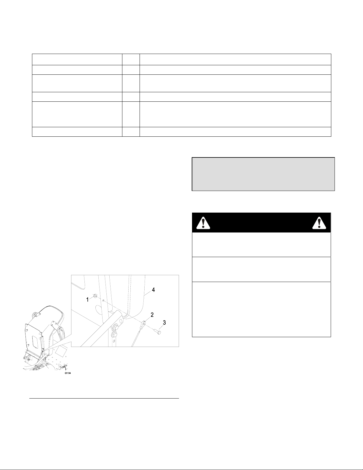
Fasten Seat
1. Remove the nut and bolt from the loose end of the
lanyard.
2. Tilt seat downward and align lanyard to the hole in
the side of the seat (See Figure 1).
3. Install bolt and nut. Tighten bolt and then loosen
nut 1/4-1/2 turn so that lanyard end rotates freely.
Verify that lanyard is free to rotate on both ends so
that it pulls straight while supporting the seat.
Figure 1
1. Nut 3. Bolt
2. Lanyard 4. Seat
Servicing the Battery
WARNING: Battery posts, terminals, and related
accessories contain lead compounds, chemicals
known to the State of California to cause cancer and
reproductive harm. Wash
hands after handling.
The machine is shipped with a filled lead
acid battery.
DANGER
POTENTIAL HAZARD
♦ Charging the battery may produce explosive
gasses
WHAT CAN HAPPEN
♦ Battery gasses can explode causing serious
injury.
HOW TO AVOID THE HAZARD
♦ Keep sparks, flames, or cigarettes away from
battery.
♦ Ventilate when charging or using battery in an
enclosed space.
♦ Make sure venting path of battery is always
open once battery is filled with acid.
1. Tilt seat up to gain access to the battery.
2. Check the voltage of the battery with a digital
voltmeter. Locate the voltage reading of the
battery in the table below and charge the battery
for the recommended time interval to bring the
charge up to a full charge of 12.6 volts or
greater.
Page 2
Page 3
IMPORTANT: Make sure the negative battery
cables are disconnected and the battery charger
used for charging the battery has an output of 16
volts and 7 amps or less to avoid damaging the
battery (see chart below for recommended charger
settings).
Voltage
Reading
Percent
Charge
12.6 or greater 100%
12.4 – 12.6 75 – 100%
12.2 – 12.4 50 – 75%
12.0 – 12.2 25 – 50%
11.7 – 12.0 0 – 25%
11.7 or less 0%
Maximum
Charger
Settings
16 volts /
7 amps
16 volts /
7 amps
16 volts /
7 amps
14.4 volts /
4 amps
14.4 volts /
4 amps
14.4 volts /
2 amps
Charging
Interval
No Charging
Required
30 Minutes
1 Hour
2 Hours
3 Hours
6 Hours
or More
2. Position the lever so the bottom hole aligns with
hole in the control arm shaft. Install spring disc
washer and bolt.
3. Repeat on opposite side of unit.
NOTE: There are two lever height options
available. Place the levers in the top two holes
to increase height of the levers, or in the bottom
two holes to decrease the height of the levers.
CAUTION
POTENTIAL HAZARD
♦ If the ignition is in the “ON” position there is
potential for sparks and engagement of
components.
WHAT CAN HAPPEN
♦ Sparks could cause an explosion or moving
parts could accidentally engage causing
personal injury.
HOW TO AVOID THE HAZARD
♦ Be sure ignition switch is in the “OFF” position
before charging the battery.
3. Connect the negative battery cables.
NOTE: If the positive cable is also disconnected,
connect the positive (red) cable to the positive
battery terminal first, then the negative (black)
cable to the negative battery terminal. Slip
insulator boot over the positive terminal.
NOTE: If time does not permit charging the
battery, or if charging equipment is not available,
connect the negative battery cables and run the
vehicle continuously for 20 to 30 minutes to
sufficiently charge the battery
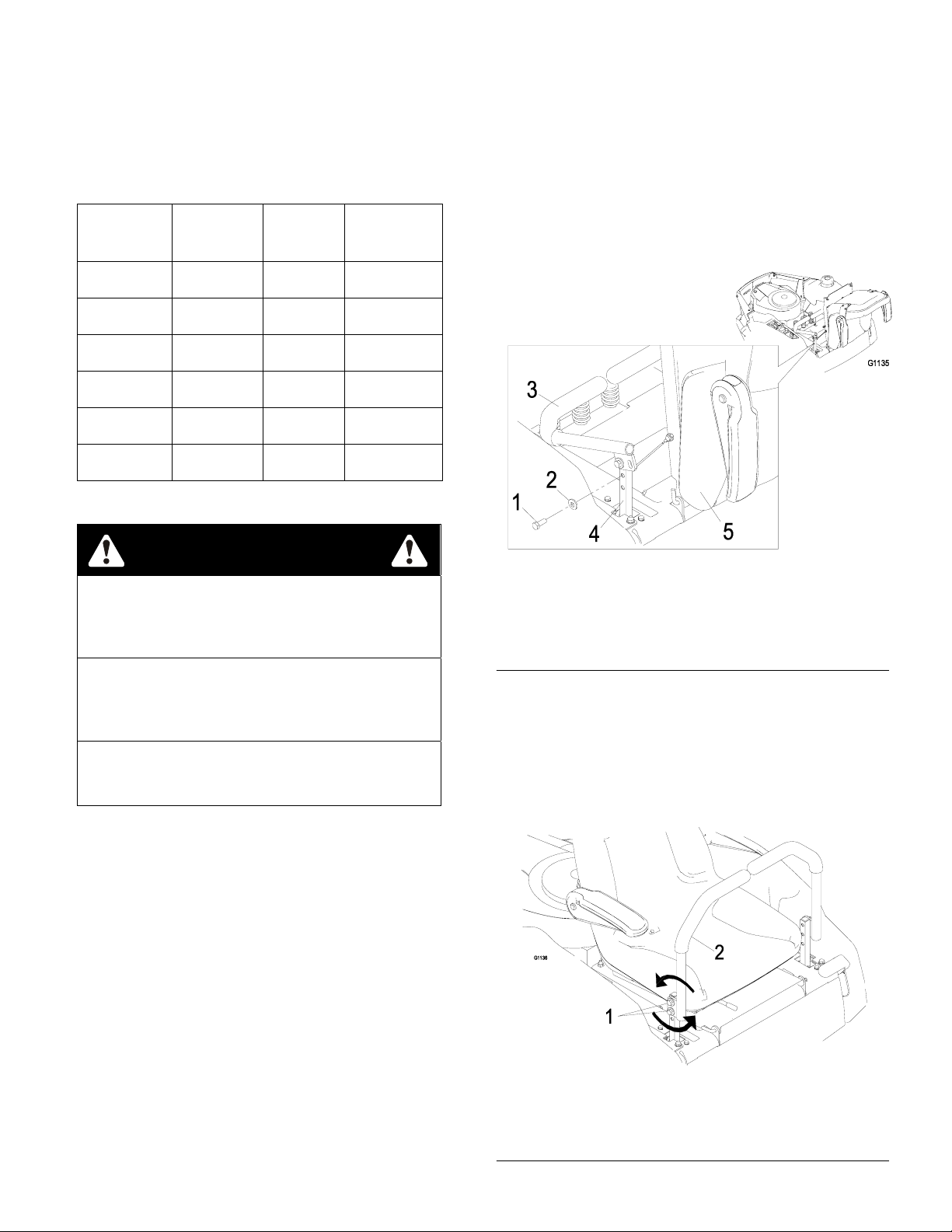
Installing the Motion Control Levers
1. Remove the bottom 3/8” x 1” bolt and spring disc
washer from the control arm shaft. Loosen the
upper 3/8” x 1” bolt and spring disc washer in the
control lever so that the lever can rotate (See
Figure 2).
.
Figure 2
1. Bolt 4. Control Arm Shaft
2. Spring Disc Washer 5. Seat
3. Motion Control Lever
4. Align the levers front/rear position. With the
levers in the neutral position, loosen the
hardware and adjust the levers sliding and/or
tilting the lever(s) forward or backward until
properly aligned and tighten hardware
(Figure. 3).
Figure 3
1. Hardware
2. Motion Control Lever
Page 3
Page 4

Servicing the Engine
Engine is shipped with oil; check oil level and if
necessary fill to the appropriate level with oil as
specified in Engine Owner’s Manual.
Servicing the Hydraulic Oil
The machine is shipped with hydraulic oil. Verify level
on Expansion Tank. (See Figure 5)
1. Start engine and drive the machine forward and
backward for a few minutes to allow any extra air
to purge out of the hydraulic system.
2. Stop engine and wait for all moving parts to stop.
Remove key and engage parking brake.
3. Check expansion tank and if necessary add
MOBIL 1 15W-50 synthetic motor oil to the FULL
COLD line.
NOTE: The proper amount of oil should have
been added at the factory. If the reservoir is
slightly over full, do not remove fluid. The level
will go down once all of the air is purged from the
system.
Figure 5
1. Seat 3. Expansion Tank
2. Engine
4. Replace expansion tank cap and tighten until
snug. Do not overtighten.
Installing the Discharge Deflector
1. Install discharge deflector (Figure 6).
2. Place the spring on the rod. Slide rod, straight
end, through the front discharge deflector
bracket, discharge deflector, and rear deflector
bracket.
3. Make sure that the spring and rod are installed
so that the rod is retained from sliding out by the
front bracket and the spring holds the discharge
deflector in the down position. Refer to
(Figure 6) for proper orientation.
Important: The discharge deflector must be
spring loaded in the down position. Lift the
deflector up to test that it snaps to the full
down position.
1. Mower deck 4. Spring
2. Discharge deflector 5. Rod
3. Discharge deflector bracket 6. Assembled view
Figure 6
© 2007 The Toro Company Contact us at www.Toro.com.
8111 Lyndale Ave. South All Rights Reserved
Bloomington, MN 55420 Printed in the USA.
Page 4
 Loading...