

Page 1

FormNo.3398-917RevB
TimeCutter
®
SW4200orSW5000
RidingMower
ModelNo.74784—SerialNo.316000001andUp
ModelNo.74790—SerialNo.316000001andUp
Registeratwww.T oro.com.
OriginalInstructions(EN)
*3398-917*B
Page 2
WARNING
Introduction
CALIFORNIA
Proposition65Warning
Thisproductcontainsachemical
orchemicalsknowntotheStateof
Californiatocausecancer,birthdefects,
orreproductiveharm.
Theengineexhaustfromthisproduct
containschemicalsknowntotheStateof
Californiatocausecancer,birthdefects,
orotherreproductiveharm.
ItisaviolationofCaliforniaPublicResourceCode
Section4442or4443touseoroperatetheengineon
anyforest-covered,brush-covered,orgrass-covered
landunlesstheengineisequippedwithaspark
arrester,asdenedinSection4442,maintainedin
effectiveworkingorderortheengineisconstructed,
equipped,andmaintainedforthepreventionofre.
ThissparkignitionsystemcomplieswithCanadian
ICES-002
WARNING
Thismachineisaride-on,rotary-bladelawnmower
intendedtobeusedbyhomeownersinresidential
applications.Itisprimarilydesignedforcuttinggrass
onwell-maintainedlawns.Itisnotdesignedforcutting
brush,mowinggrassandothergrowthalongside
highways,orforagriculturaluses.
Readthisinformationcarefullytolearnhowtooperate
andmaintainyourproductproperlyandtoavoid
injuryandproductdamage.Youareresponsiblefor
operatingtheproductproperlyandsafely .
YoumaycontactTorodirectlyatwww.Toro.com
forproductsafetyandoperationtrainingmaterials,
accessoryinformation,helpndingadealer,orto
registeryourproduct.
Wheneveryouneedservice,genuineToroparts,or
additionalinformation,contactanAuthorizedService
DealerorToroCustomerServiceandhavethemodel
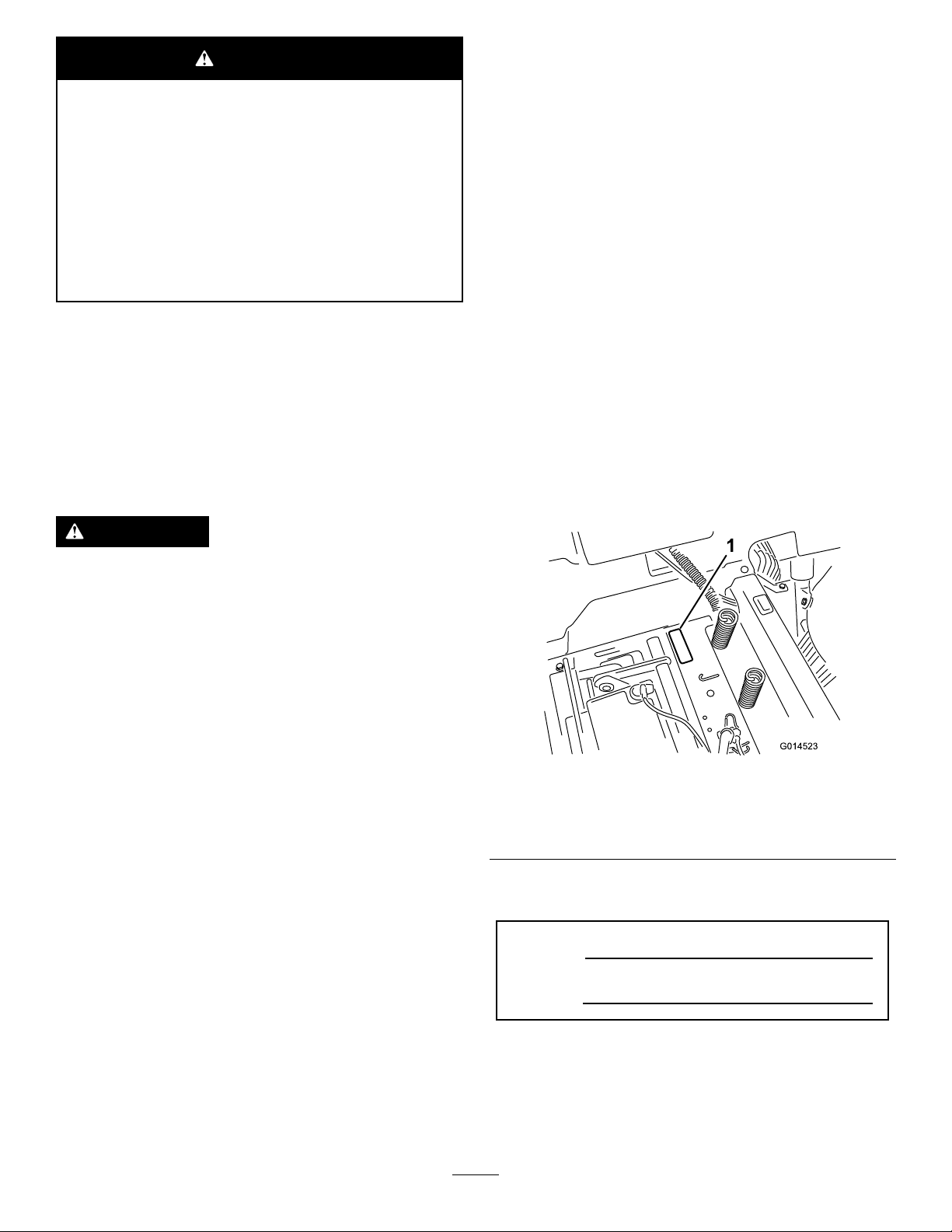
andserialnumbersofyourproductready.Figure1
identiesthelocationofthemodelandserialnumbers
ontheproduct.Writethenumbersinthespace
provided.
Removingstandardoriginalequipmentparts
andaccessoriesmayalterthewarranty,
traction,andsafetyofthemachine.Failureto
useoriginalT oropartscouldcauseserious
injuryordeath.Makingunauthorizedchanges
totheengine,fuelorventingsystem,may
violateEPAandCARBregulations.
Replaceallpartsincluding,butnotlimited
to,tires,belts,blades,andfuelsystem
componentswithoriginalToroparts.
Theenclosedengineowner’smanualissupplied
forinformationregardingtheUSEnvironmental
ProtectionAgency(EPA)andtheCaliforniaEmission
ControlRegulationofemissionsystems,maintenance,
andwarranty.Replacementsmaybeorderedthrough
theenginemanufacturer.
Thegrossornethorsepowerofthisenginewas
laboratoryratedbytheenginemanufacturerin
accordancewiththeSocietyofAutomotiveEngineers
(SAE)J1940.Asconguredtomeetsafety,emission,
andoperatingrequirements,theactualenginetorque
onthisclassofmowerwillbesignicantlylower.
g014523
Figure1
Undertheseat
1.Modelandserialnumberplate
Writetheproductmodelandserialnumbersinthe
spacebelow:
ModelNo.
SerialNo.
Gotowww.Toro.comtoviewspecicationsonyour
mowermodel.
©2017—TheToro®Company
8111LyndaleAvenueSouth
Bloomington,MN55420
Thismanualidentiespotentialhazardsandhas
safetymessagesidentiedbythesafety-alertsymbol
(Figure2),whichsignalsahazardthatmaycause
seriousinjuryordeathifyoudonotfollowthe
recommendedprecautions.
Contactusatwww.Toro.com.
2
PrintedintheUSA
AllRightsReserved
Page 3

Figure2
1.Safety-alertsymbol.
Thismanualuses2wordstohighlightinformation.
Importantcallsattentiontospecialmechanical
informationandNoteemphasizesgeneralinformation
worthyofspecialattention.
Contents
Safety.......................................................................4
SafeOperatingPractices....................................4
ToroRidingMowerSafety...................................7
SlopeIndicator...................................................8
SafetyandInstructionalDecals..........................9
ProductOverview...................................................16
Controls...........................................................16
Operation................................................................17
AddingFuel......................................................17
CheckingtheEngine-OilLevel..........................18
BreakinginaNewMachine..............................18
ThinkSafetyFirst..............................................19
StartingtheEngine...........................................21
OperatingtheSmartPark
Brake............................................................21
OperatingtheBlades........................................21
StoppingtheEngine.........................................21
DrivingtheMachine..........................................22
StoppingtheMachine.......................................22
MowinginReverse...........................................22
AdjustingtheHeightofCut...............................23
PositioningtheSeat..........................................23
PositioningtheSteeringWheel.........................24
AdjustingtheAnti-scalpRollers........................24
AdjustingtheAnti-scalpRollers........................24
PushingtheMachinebyHand..........................25
UsingtheGrassDeector.................................26
TransportingtheMachine.................................26
LoadingtheMachine........................................27
OperatingTips.................................................28
Maintenance...........................................................30
RecommendedMaintenanceSchedule(s)...........30
Pre-MaintenanceProcedures..............................30
RaisingtheSeat...............................................30
RaisingtheFrontoftheMachine.......................31
Lubrication..........................................................31
GreasingtheBearings......................................31
EngineMaintenance...........................................32
ServicingtheAirCleaner..................................32
ServicingtheEngineOil....................................33
ServicingtheSparkPlug...................................35
CleaningtheCoolingSystem............................37
™
Parking
FuelSystemMaintenance...................................37
ReplacingtheIn-LineFuelFilter.......................37
g000502
ElectricalSystemMaintenance...........................38
ChargingtheBattery.........................................38
ServicingtheFuses..........................................40
DriveSystemMaintenance..................................40
CheckingtheTirePressure...............................40
ReleasingtheElectricBrake.............................41
MowerMaintenance.............................................41
ServicingtheCuttingBlades.............................41
LevelingtheMowerDeck..................................44
RemovingtheMowerDeck...............................46
MowerBeltMaintenance..................................47
InstallingtheMower..........................................48
ReplacingtheGrassDeector..........................48
Cleaning..............................................................49
CleaningUndertheFrontofthe
Machine........................................................49
WashingtheUndersideoftheMower
Deck..............................................................49
Storage...................................................................50
CleaningandStorage.......................................50
Troubleshooting......................................................52
Schematics.............................................................54
3
Page 4

Safety
Improperuseormaintenancebytheoperatoror
ownercanresultininjury.Toreducethepotential
forinjury,complywiththesesafetyinstructions,and
payattentiontothesafetyalertsymbol,whichmeans
Caution,Warning,orDanger—personalsafety
instruction.Failuretocomplywiththeinstructions
mayresultinpersonalinjuryordeath.
•Donotoperatethemachinewithoutdeector,
dischargecoverorentiregrasscollectionsystem
inplaceandworking.
•Bealert,slowdownandusecautionwhenmaking
turns.Lookbehindandtothesidebeforechanging
directions.
•Neverleavearunningmachineunattended.
Alwaysturnoffblades,setparkingbrake,shut
offtheengine,andremovethekeybefore
dismountingthemachine.
SafeOperatingPractices
Thisproductiscapableofamputatinghandsand
feetandthrowingobjects.Alwaysfollowallsafety
instructionstoavoidseriousinjuryordeath.
ThefollowinginstructionsareadaptedfromANSI
standardB71.1-2012.Allthelanguagewithinthis
ANSIstandardappliestothismachine;however,
duetotheapplicationofthestandardacrossmany
differenttypesofproductssomestatementscan
seemgeneralormisleading.Intheseinstances,T oro
hasrenedthestatementtoconveythemeaningof
thestandardwhilebettermatchingtheproductthis
Operator'sManualpertains.Safetyinformationin
additiontotheinstructionsfoundintheANSIstandard
belowcanbefoundinToroRidingMowerSafetyat
theendofthissection.
GeneralOperation
•Read,understand,andfollowallinstructionsin
theOperator'sManualandonthemachinebefore
starting.
•Donotplaceyourhandsorfeetnearrotatingparts
orunderthemachine.Keepclearofthedischarge
openingatalltimes.
•Turnoffthebladeswhennotmowing.Shut
offtheengine,waitforallpartstocometo
acompletestop,andremovethekeybefore
cleaningthemachine,removingthegrasscatcher
oruncloggingthedischargechute.
•Operatethemachineonlyindaylightorgood
articiallight.
•Donotoperatethemachinewhiletired,ill,or
undertheinuenceofalcoholordrugs.
•Watchfortrafcwhenoperatingnearorcrossing
roadways.
•Useextracarewhenloadingorunloadingthe
machineintoatrailerortruck.
•Wearappropriateclothingincludingeyeprotection
andsubstantial,slip-resistantshoes.Tiebacklong
hair.Donotwearjewelry.
•Alwaysfollowtherecommendationsforany
applicationofcounterweights.
•Lightningcancausesevereinjuryordeath.If
lightningisseenorthunderisheardinthearea,do
notoperatethemachine;seekshelter.
SlopeOperation
•Allowonlyresponsibleadultswhoarefamiliarwith
theinstructionstooperatethemachine.
•Cleartheareaofobjectssuchasrocks,toys,wire,
etc.,whichcouldbepickedupandthrownbythe
blade.
•Besuretheareaisclearofotherpeoplebefore
mowing.Stopthemachineifanyoneentersthe
area.
•Nevercarrypassengers.
•Donotmowinreverseunlessabsolutely
necessary.Alwayslookdownandbehindbefore
andwhilebackingup.
•Beawareofthemowerdischargedirectionanddo
notpointitatanyone.Avoiddischargingmaterial
againstawallorobstruction.Materialmayricochet
backtowardyou.Stoptheblade(s)whencrossing
gravelsurfaces.
Slopesareamajorfactorrelatedtolossofcontroland
tip-overaccidents,whichcanresultinsevereinjuryor
death.Operationonallslopesrequiresextracaution.
Ifyoucannotbackuptheslopeorifyoufeeluneasy
onit,donotmowit.
•Donotmowslopesgreaterthan15degrees.
•Watchforditches,holes,rocks,dips,andrises
thatchangetheoperatingangle,asroughterrain
couldoverturnthemachine.
•Choosealowgroundspeedsothatyouwillnot
havetostopwhileoperatingonaslope.
•Donotmowslopeswhengrassiswet.Slippery
conditionsreducetractionandcouldcausesliding
andlossofcontrol.
•Alwayskeepthedrivewheelsengagedwhen
goingdownslopes.
4
Page 5

•Reducespeedanduseextremecautiononslopes.
•Donotmakesuddenturnsorrapidspeedchanges.
•Removeormarkobstaclessuchasrocks,tree
limbs,etc.fromthemowingarea.Tallgrasscan
hideobstacles.
•Avoidsuddenstartswhenmowinguphillbecause
themowermaytipbackward.
•Beawarethatlossoftractionmayoccurgoing
downhill.Weighttransfertothefrontwheels
maycausedrivewheelstoslipandcauselossof
brakingandsteering.
•Alwaysavoidsuddenstartingorstoppingona
slope.Ifthetireslosetraction,stopthemachine,
disengagethebladesandproceedslowlydown
theslope.
•Useextremecarewithgrasscatchersorother
attachments.Thesecanchangethestabilityofthe
machineandcauselossofcontrol.
•Donottrytostabilizethemachinebyputtingyour
footontheground.
•Donotmowneardrop-offs,ditches,steepbanks,
orwater.Wheelsdroppingoveredgescancause
rollovers,whichmayresultinseriousinjury,death
ordrowning.
•Useawalkbehindmowerand/orahandtrimmer
neardrop-offs,ditches,steepbanks,orwater.
TowingSafety
•Donotattachtowedequipmentexceptatthehitch
point.
•Followtheattachmentmanufacturer's
recommendationforweightlimitsfortowed
equipmentandtowingonslopes.Towedweight
mustnotexceedtheweightofthemachine,
operator,andballast.Usecounterweightsor
wheelweightsasdescribedintheattachment,or
inthetowingmachineOperator’sManual.
•Neverallowchildrenorothersinorontowed
equipment.
•Onslopes,theweightofthetowedequipmentmay
causelossoftraction,increasedriskofrollover,
andlossofcontrol.Reducethetowedweightand
slowdown.
•Thestoppingdistanceincreaseswiththeweight
ofthetowedload.Travelslowlyandallowextra
distancetostop.
•Makewideturnstokeeptheattachmentclearof
themachine.
Children
Tragicaccidentscanoccuriftheoperatorisnot
alerttothepresenceofchildren.Childrenareoften
attractedtothemachineandthemowingactivity.
Neverassumethatchildrenwillremainwhereyou
lastsawthem.
•Keepchildrenoutofthemowingareaandunder
thewatchfulcareofanotherresponsibleadult,not
theoperator.
•Bealertandturnthemachineoffifchildrenenter
thearea.
•Beforeandwhilebackingorchangingdirection,
lookbehind,down,andside-to-sideforsmall
children.
•Nevercarrychildrenonthemachine,evenwiththe
bladesoff.Childrenmayfalloffandbeseriously
injuredorinterferewiththesafeoperationofthe
machine.
•Childrenwhohavebeengivenridesinthepast
maysuddenlyappearinthemowingareafor
anotherrideandberunoverorbackedoverby
themower.
•Neverallowchildrentooperatethemachine.
•Useextracarewhenapproachingblindcorners,
shrubs,trees,theendofafence,orotherobjects
thatmayobscurevision.
5
Page 6

Service
SafeHandlingofGasoline
Toavoidpersonalinjuryorpropertydamage,use
extracarewhenhandlinggasolineandotherfuels.
Theyareammableandthevaporsareexplosive.
•Extinguishallcigarettes,cigars,pipes,andother
sourcesofignition.
•Useonlyanapprovedcontainer.
•Neverremovethefuelcaporaddfuelwhenthe
engineisrunning.Allowtheenginetocoolbefore
refueling.
•Neverrefuelthemachineindoors.
•Neverstorethemachineorfuelcontainerinside
wherethereisanopename,suchasneara
waterheaterorfurnace.
•Neverllcontainersinsideavehicleorona
truckortrailerwithaplasticliner.Alwaysplace
containersontheground,awayfromyourvehicle
beforelling.
•Removefuel-poweredequipmentfromthetruck
ortrailerandrefuelitontheground.Ifthis
isnotpossible,thenrefuelsuchequipment
withaportablecontainerratherthanfroma
gasoline-dispensernozzle.
•Keepthenozzleincontactwiththerimofthefuel
tankorcontaineropeningatalltimesuntilthe
fuelingiscomplete.Donotuseanozzlelock-open
device.
•Ifyouspillfuelonclothing,changeyourclothing
immediately.
•Neveroverllthefueltank.Replacethefuelcap
andtightenitsecurely.
•Nevermakeanyadjustmentsorrepairswiththe
enginerunning.
•Grasscatchercomponentsaresubjecttowear,
damage,anddeterioration,whichcouldexpose
movingpartsorallowobjectstobethrown.
Frequentlycheckcomponentsandreplacethem
withthemanufacturers'recommendedparts,when
necessary.
•Mowerbladesaresharpandcancut.Wrapthe
blade(s)orwearthickly-paddedglovesanduse
extracautionwhenservicingthem.
•Checkforproperbrakeoperationfrequently.
Adjustandservicethemasrequired.
•Maintainorreplacesafetyandinstructiondecals
asnecessary.
•UseonlygenuineT ororeplacementpartsto
ensurethattheoriginalstandardsaremaintained.
GeneralService
•Neveroperateamachineinsideaclosedarea.
Engineexhaustcontainscarbonmonoxide,which
isanodorless,deadlypoisonthatcankillyou.
•Keepnutsandboltstight,especiallytheblade
attachmentbolts.Keepequipmentingood
condition.
•Neverinterferewiththeintendedfunctionofa
safetydeviceortoreducetheprotectionprovided
byasafetydevice.Checktheirproperoperation
regularly.
•Keepthemachinefreeofgrass,leaves,orother
debrisbuildup.Cleanupoilorfuelspillsand
fuel-soakeddebris.Allowthemachinetocool
beforestoringit.
•Stopandinspecttheequipmentifyoustrikean
object.Repair,ifnecessary ,beforestartingthe
machine.
6
Page 7

ToroRidingMowerSafety
Thefollowinglistcontainssafetyinformationspecic
toT oroproductsorothersafetyinformationthatyou
mustknowthatmaynotbeincludedintheANSI
standards.
•Stoptheengine,disengagetheblade-control
switch,removekeybeforeanddisconnectspark
plugwire(s)performinganyservice,repairs,
maintenanceoradjustments.
•Keephands,feet,hair,andlooseclothingaway
fromattachmentdischargearea,undersideof
mowerandanymovingpartswhileengineis
running.
•Donottouchequipmentorattachmentpartswhich
maybehotfromoperation.Allowthemtocool
beforeattemptingtomaintain,adjust,orservice
them.
•Batteryacidispoisonousandcancauseburns.
Avoidcontactwithskin,eyes,andclothing.Protect
yourface,eyes,andclothingwhenworkingwitha
battery.
•Batterygasescanexplode.Keepcigarettes,
sparksandamesawayfromthebattery.
•UseonlyT oroapprovedattachments.Y oumay
voidthewarrantyifyouusethemachinewith
unapprovedattachments.
•Ifloadingthemachineontoatrailerortruck,use
asingle,full-widthramponly.Therampangle
shouldnotexceed15degrees.
7
Page 8
SlopeIndicator
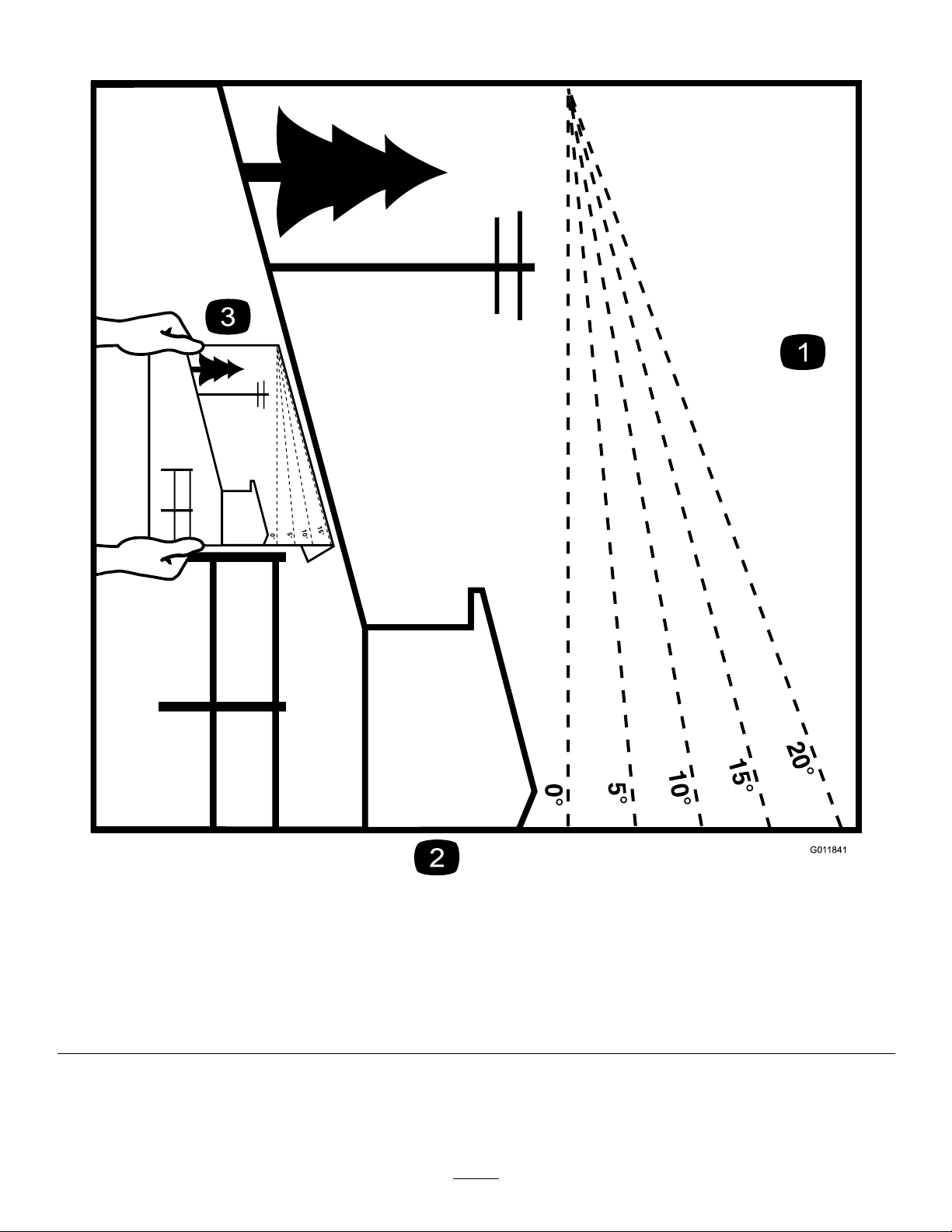
Figure3
Thispagemaybecopiedforpersonaluse.
1.Themaximumslopeyoucansafelyoperatethemachineonis15degrees.Usetheslopecharttodeterminethedegreeofslope
ofhillsbeforeoperating.Donotoperatethismachineonaslopegreaterthan15degrees.Foldalongtheappropriateline
tomatchtherecommendedslope.
2.Alignthisedgewithaverticalsurface,atree,building,fencepole,etc.
3.Exampleofhowtocompareslopewithfoldededge.
8
g011841
Page 9
SafetyandInstructionalDecals
Safetydecalsandinstructionsareeasilyvisibletotheoperatorandarelocatednearanyarea
ofpotentialdanger.Replaceanydecalthatisdamagedorlost.
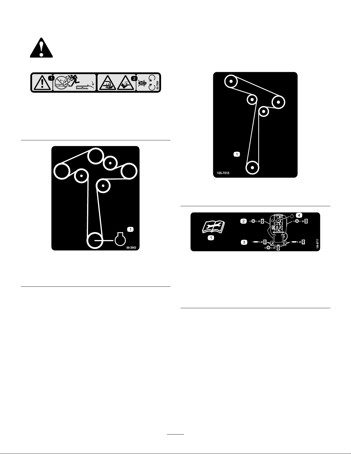
93-7009
1.Warning—don'toperatethemowerwiththedeectorupor
removed;keepthedeectorinplace.
2.Cutting/dismembermenthazardofhandorfoot,mower
blade—stayawayfrommovingparts.
decal93-7009
decal105-7015
105-7015
Formodelswith42-inchdecks
99-3943
Formodelswith50-inchand54-inchmowerdecks
1.Engine
decal99-3943
decal106-8717
106-8717
1.Readtheinstructionsbeforeservicingorperforming
maintenance.
2.Checktirepressureevery25operatinghours.
3.Greaseevery25operatinghours.
4.Engine
9
Page 10
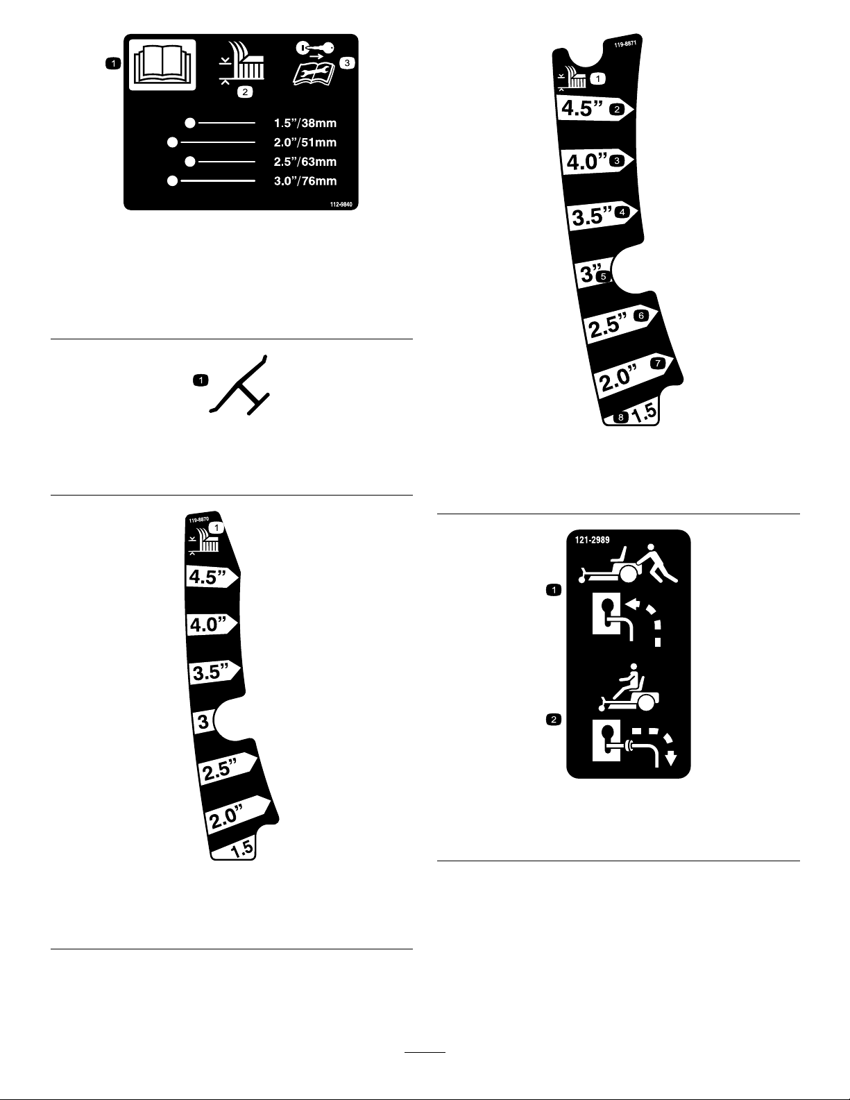
decal112-9840
112-9840
1.ReadtheOperator's
Manual.
3.Removetheignitionkey
andreadtheinstructions
beforeservicingor
performingmaintenance.
2.Height-of-cut
Manufacturer'sMark
1.Indicatesthebladeisidentiedasapartfromtheoriginal
machinemanufacturer.
decaloemmarkt
decal119-8871
119-8871
42InchModel
1.Height-of-cut
decal121-2989b
121-2989
1.Bypassleverpositionfor
pushingthemachine
decal119-8870
2.Bypassleverpositionfor
operatingthemachine
119-8870
50-inchand54-inchModels
1.Height-of-cut
10
Page 11
decalbatterysymbols
BatterySymbols
Someorallofthesesymbolsareonyourbattery .
1.Explosionhazard
2.Nore,opename,or
6.Keepbystandersasafe
7.Weareyeprotection;
smoking
3.Causticliquid/chemical
8.Batteryacidcancause
burnhazard
4.Weareyeprotection.9.Flusheyesimmediately
5.ReadtheOperator's
10.Containslead;donot
Manual.
distancefromthebattery.
explosivegasescan
causeblindnessandother
injuries.
blindnessorsevereburns.
withwaterandgetmedical
helpfast.
discard
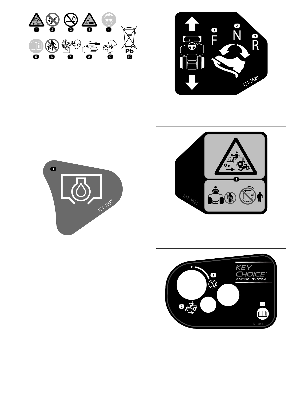
decal131-3620
131-3620
1.Pedalposition—forward
2.Pedalposition—neutral
3.Pedalposition—reverse
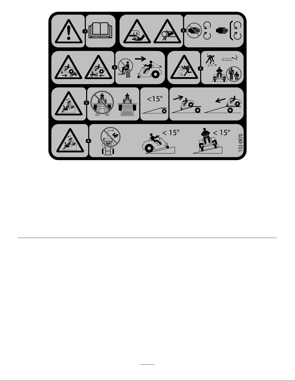
decal131-3621b
131-3621
1.Oildrain
1.Crushing/dismembermenthazardofbystanders—keep
decal131-1097
131-1097
bystandersawayfromthemachine;donotstartthe
machinewithbystandersnearby.
decal131-3664
131-3664
1.Spinningblade3.Operator'sManual
2.Reverse
11
Page 12

decal131-3665
131-3665
1.Bladespinning
3.ReadtheOperator's
2.Reverse
131-3954
1.On2.Off
Manual.
decal132-6863
132-6863
decal131-3954
decal132-0872
132-0872
1.Thrownobject
hazard—keepbystanders
awayfromthemachine.
2.Thrownobjecthazard,
raisedbafe—donot
operatethemachinewith
anopendeck;usea
baggerorabafe.
3.Severinghazardofhand
orfoot—keepawayfrom
movingparts.
4.Entanglement
hazard—keepaway
frommovingparts;keep
allguardsandshieldsin
place.
131-3955
1.On2.Off
decal131-3955
12
Page 13
decal132-0870
132-0870
1.Warning—readtheOperator'sManual.
2.Cuttinghazardofhand,mowerblade;
pinchinghazardofhand,belt—keep
handsandfeetawayfrommoving
parts;keepallguardsandshieldsin
place.
3.Bodilyharmhazard—noriders;look
behindyouwhenmowinginreverse.
4.Thrownobjecthazard—keep
bystandersawayfromthemachine;
removedebrisfromtheareabefore
mowing;keepthedeectorshield
down.
5.Ramptippinghazard—whenloading
ontoatrailer,donotusedualramps;
onlyuseasinglerampwideenough
forthemachineandthathasanincline
lessthan15degrees;backupthe
ramp(inreverse)anddriveforwardoff
theramp.
6.Tippinghazardonslopes—donot
makesharp,quickturns;donotuse
slopesgreaterthan15degrees.
13
Page 14
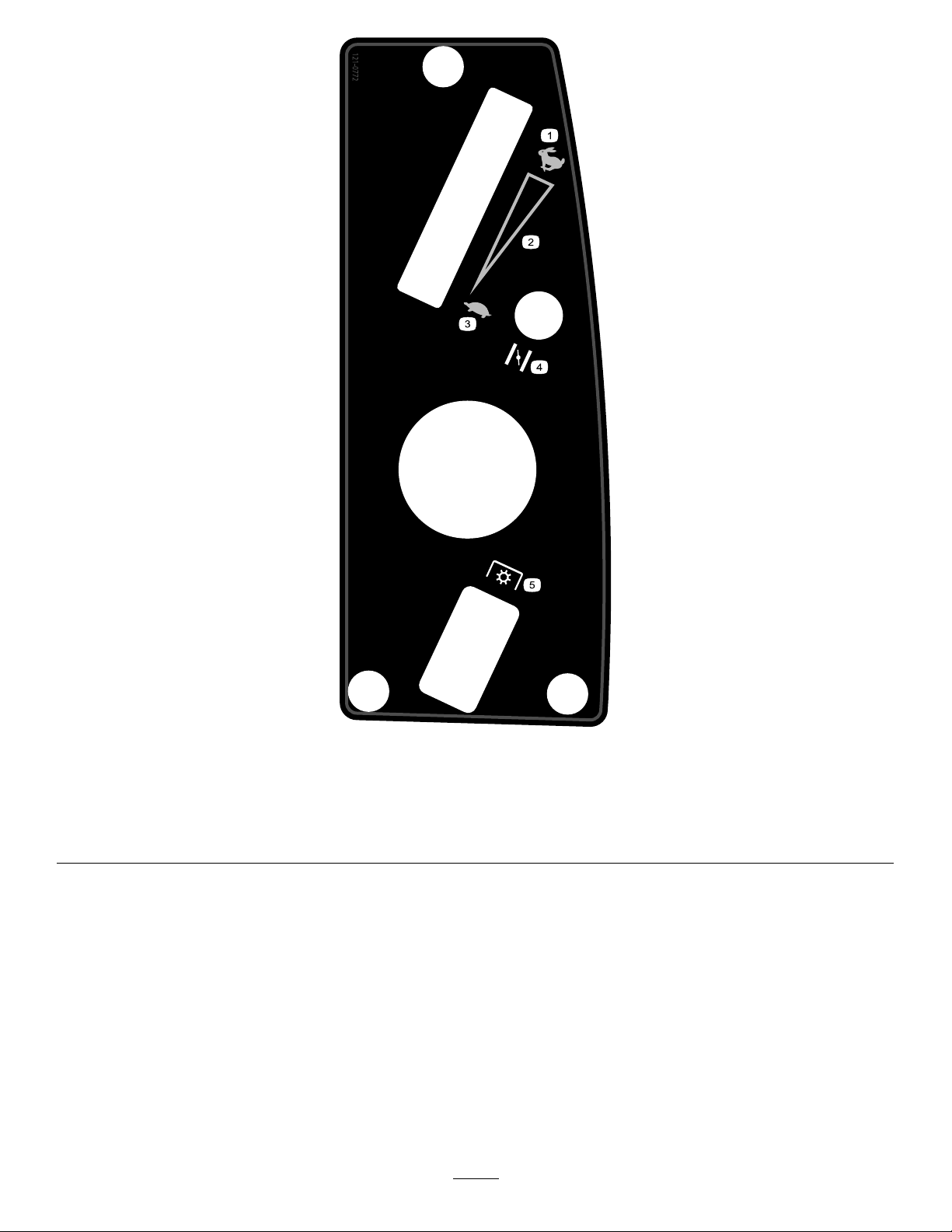
121-0772
Modelswith42inchmowerdeck
decal121-0772
1.Fast
4.Choke
2.Continuous-variablesetting5.Powertake-off(PTO),blade-controlswitch
3.Slow
14
Page 15
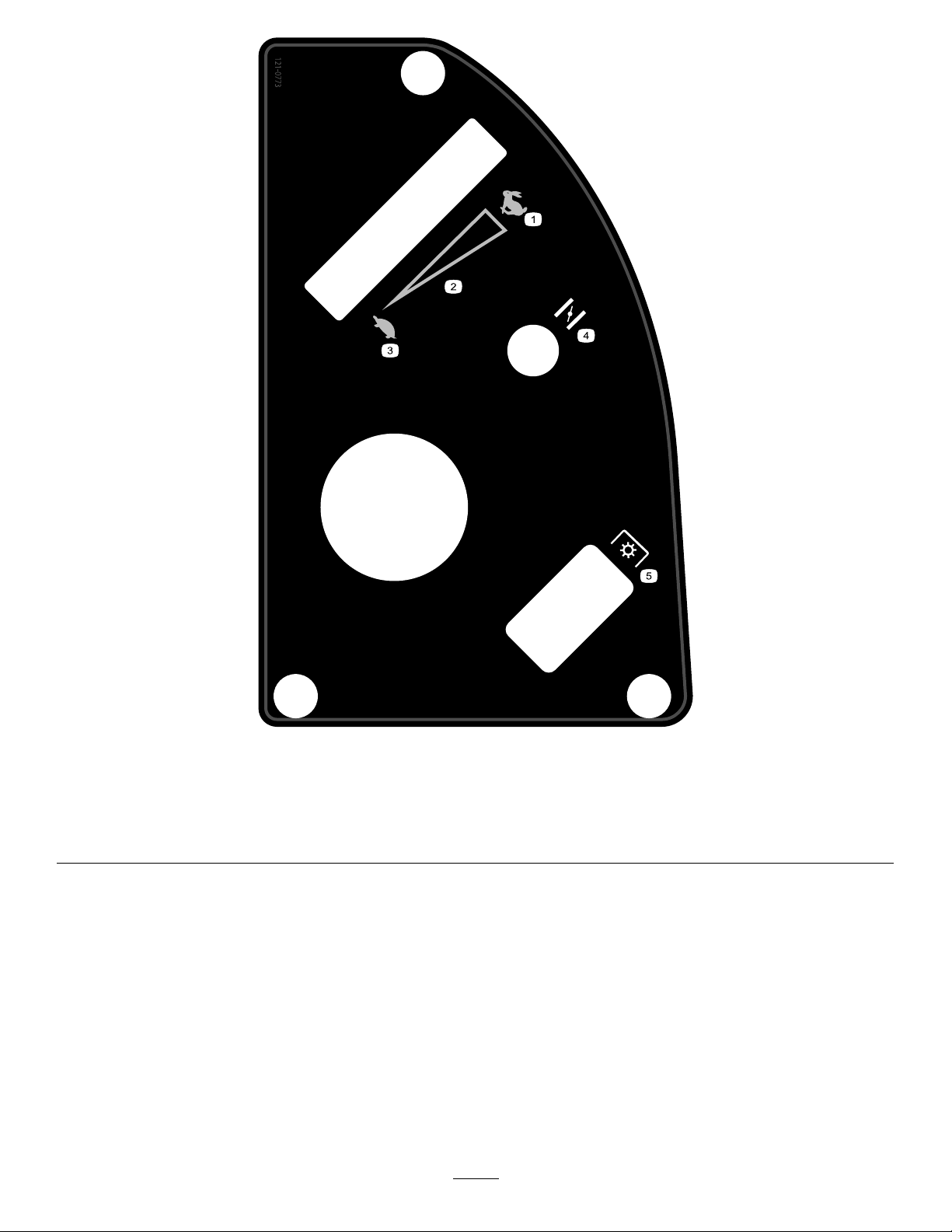
121-0773
Modelswith50inchmowerdeck
decal121-0773
1.Fast
4.Choke
2.Continuous-variablesetting5.Powertake-off(PTO),blade-controlswitch
3.Slow
15
Page 16
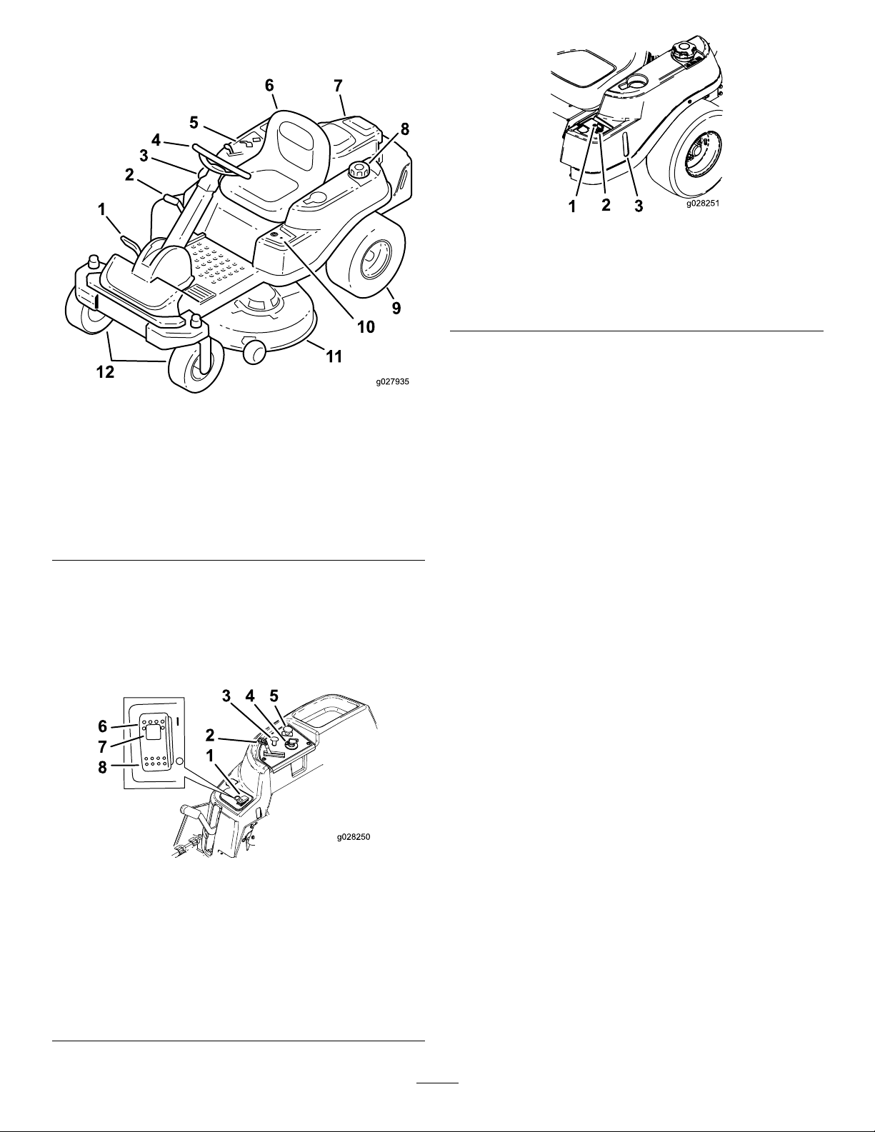
ProductOverview
g028251
Figure6
Figure4
1.Traction-controlpedal7.Engine
2.Height-of-cutlever
3.SmartPark
4.Steeringwheel10.KeyChoice
5.Controlpanel
6.Operatorseat
™
switch
8.Fuel-tankcap
9.Reardrivewheel
11.Mowerdeck
12.Frontcasterwheels
®
control
Controls
BecomefamiliarwithallcontrolsinFigure5and
Figure6beforeyoustarttheengineandoperatethe
machine.
1.Operating-in-reverse
warninglight
2.KeyChoicekey(bluein
color)
3.Fuel-presencewindow
IgnitionSwitch
g027935
Theignitionswitchhas3positions—OFF,RUN,and
START.ThekeyturnstotheSTARTpositionandmoves
backtotheRUNpositionuponrelease.Turningthe
keytotheOFFpositionstopstheengine.Always
removethekeywhenleavingthemachinetoprevent
someonefromaccidentallystartingtheengine(Figure
5).
ChokeControl
Usethechoketostartacoldengine.Pullthechoke
knobuptoengageit.Pushdownthechokeknobto
disengageit(Figure5).
ThrottleControl
ThethrottlecontrolisvariablebetweentheFAST
andSLOWpositions.Movingthrottleleverforward
increasestheenginespeedandmovingitrearward
decreasestheenginespeed(Figure5).
1.SmartPark™switch
2.Throttle
3.Choke
4.Ignitionswitch
ControlPanel
Figure5
5.Blade-controlswitch
(powertakeoff)
6.Parkingbrake—On
7.Parking-brakeindicator
light
8.Parkingbrake—Off
Blade-ControlSwitch(Power
Takeoff)
Theblade-controlswitch(PTO)engagesand
disengagespowertothemowerblades(Figure5).
g028250
Fuel-PresenceWindow
Usethefuelwindow,locatedontheleftsideofthe
machine,toverifythepresenceofgasolineinthetank
(Figure6).
Height-of-CutLever
Theheight-of-cutleverallowsyoutolowerandraise
thedeckfromtheseatedposition.Whenyouraisethe
lever(towardyou),thedeckisraisedfromtheground,
16
Page 17

andwhenyoulowerit(awayfromyou),itlowersto
theground.Adjusttheheightofcutonlywhilethe
machineisnotmoving(Figure14).
KeyChoice
®
Switch
Operation
Note:Determinetheleftandrightsidesofthe
machinefromthenormaloperatingposition.
Thisswitchallowsyoutomowinreversewhenit
isactivated.T oactivateit,turntheswitchtotheON
positionandreleaseitafterthePTOisengaged.T o
deactivateit,disengagethePTO(Figure6).
Operating-in-ReverseWarning
Light
Theoperating-in-reversewarninglightilluminates
wheneveryouusetheKeyChoicekeytodeactivate
theoperating-in-reverseinterlock.Itisareminderthat
theinterlocksystemisdeactivated.Thelightgoes
outwheneveryoudisengagethePTOorshutoffthe
engine.Whenthelightison,lookbehindyouanduse
extracautionwhenbackingup.
SmartPark
Theparkingbrakeisactivatedelectronically.
Engagetheparkingbrakeby1ofthefollowingactions:
•PresstheSmartPark
(Figure5).
™
Switch
™
switchtotheONposition
AddingFuel
•Forbestresults,useonlyclean,fresh(lessthan
30daysold),unleadedgasolinewithanoctane
ratingof87orhigher((R+M)/2ratingmethod).
•Ethanol:Gasolinewithupto10%ethanol
(gasohol)or15%MTBE(methyltertiarybutyl
ether)byvolumeisacceptable.Ethanoland
MTBEarenotthesame.Gasolinewith15%
ethanol(E15)byvolumeisnotapprovedforuse.
Neverusegasolinethatcontainsmorethan
10%ethanolbyvolume,suchasE15(contains
15%ethanol),E20(contains20%ethanol),orE85
(containsupto85%ethanol).Usingunapproved
gasolinemaycauseperformanceproblemsand/or
enginedamagewhichmaynotbecoveredunder
warranty.
•Donotusegasolinecontainingmethanol.
•Donotstorefueleitherinthefueltankorfuel
containersoverthewinterunlessafuelstabilizer
isused.
•Donotaddoiltogasoline.
DANGER
•Theparkingbrakeengagesautomaticallywhenthe
operatorleavestheseatandthetraction-control
pedalisinNEUTRALposition.
•Theparkingbrakeautomaticallyengages5to6
secondsaftertheignitionswitchisturnedtothe
OFFposition(ifnotalreadyengaged).
Todisengagetheparkingbrake,presstheSmartpark
switchtotheOFFpositionwiththekeyintheRUN
position.
Incertainconditions,gasolineisextremely
ammableandhighlyexplosive.Areor
explosionfromgasolinecanburnyouand
othersandcandamageproperty.
•Fillthefueltankoutdoors,inanopenarea,
whentheengineiscold.Wipeupany
gasolinethatspills.
•Neverllthefueltankinsideanenclosed
trailer.
•Donotllthefueltankcompletelyfull.Add
gasolinetothefueltankuntilthelevelis6
to13mm(1/4to1/2inch)belowthebottom
ofthellerneck.Thisemptyspaceinthe
tankallowsgasolinetoexpand.
•Neversmokewhenhandlinggasoline,and
stayawayfromanopenameorwhere
gasolinefumesmaybeignitedbyaspark.
•Storegasolineinanapprovedcontainer
andkeepitoutofthereachofchildren.
Neverbuymorethana30-daysupplyof
gasoline.
•Donotoperatewithoutentireexhaust
systeminplaceandinproperworking
condition.
17
Page 18

DANGER
Incertainconditionsduringfueling,static
electricitycanbereleased,causingaspark
thatcanignitethegasolinevapors.Areor
explosionfromgasolinecanburnyouand
othersandcandamageproperty.
Addthecorrectamountofgasoline
stabilizer/conditionertothegasoline.
Note:Afuelstabilizer/conditionerismosteffective
whenmixedwithfreshgasoline.T ominimizethe
chanceofvarnishdepositsinthefuelsystem,use
fuelstabilizeratalltimes.
•Alwaysplacegasolinecontainersonthe
groundawayfromyourvehiclebefore
lling.
•Donotllgasolinecontainersinsidea
vehicleoronatruckortrailerbed,because
interiorcarpetsorplastictruckbedliners
mayinsulatethecontainerandslowthe
lossofanystaticcharge.
•Whenpractical,removegas-powered
equipmentfromthetruckortrailerand
refueltheequipmentwithitswheelsonthe
ground.
•Ifthisisnotpossible,thenrefuelsuch
equipmentonatruckortrailerfroma
portablecontainerratherthanfroma
gasoline-dispensernozzle.
•Ifyoumustuseagasoline-dispenser
nozzle,keepthenozzleincontactwiththe
rimofthefueltankorcontaineropeningat
alltimesuntilfuelingiscomplete.
FillingtheFuelTank
Note:Ensurethattheengineisshutoff.
Note:Y oucanusethefuelwindowtoverifythe
presenceofgasolinebeforellingthetank(Figure7).
Important:Donotoverllfueltank.Fillthefuel
tanktothebottomofthellerneck.Theempty
spaceinthetankallowsthefueltoexpand.
Overllingmayresultinfuelleakage,damageto
theengine,ordamagetotheemissionssystem.
WARNING
Gasolineisharmfulorfatalifswallowed.
Long-termexposuretovaporscancause
seriousinjuryandillness.
•Avoidprolongedbreathingofvapors.
•Keepfaceawayfromnozzleandgastank
orconditionerbottleopening.
•Avoidcontactwithskin;washoffspills
withsoapandwater.
UsingStabilizer/Conditioner
Useafuelstabilizer/conditionerinthemachineto
providethefollowingbenets:
•Keepsgasolinefreshduringstorageof90daysor
less.Forlongerstorageitisrecommendedthat
thefueltankbedrained.
•Cleanstheenginewhileitruns
•Eliminatesgum-likevarnishbuildupinthefuel
system,whichcauseshardstarting
Important:Donotusefueladditives
containingmethanolorethanol.
g027243
Figure7
CheckingtheEngine-Oil Level
Beforeyoustarttheengineandusethemachine,
checktheoillevelintheenginecrankcase;referto
CheckingtheEngine-OilLevel(page33).
BreakinginaNewMachine
Newenginestaketimetodevelopfullpower.Mower
decksanddrivesystemshavehigherfrictionwhen
new,placingadditionalloadontheengine.Allow
18
Page 19

40to50hoursofbreak-intimefornewmachinesto
developfullpowerandbestperformance.
ThinkSafetyFirst
Pleasecarefullyreadallofthesafetyinstructionsand
decalsinthesafetysection.Knowingthisinformation
couldhelpyou,yourfamily ,pets,orbystandersavoid
injury.
DANGER
Operatingthemachineonwetgrassorsteep
slopescancauseslidingandlossofcontrol.
•Donotoperateonslopesgreaterthan15
degrees.
CAUTION
Thismachineproducessoundlevelsin
excessof85dBAattheoperatorsearandcan
causehearinglossthroughextendedperiods
ofexposure.
Wearhearingprotectionwhenoperatingthis
machine.
Useprotectiveequipmentforyoueyes,ears,hands,
andfeet.
•Reducespeedanduseextremecautionon
slopes.
•Donotoperatethemachinenearwater.
DANGER
Wheelsdroppingoveredgescancause
rollovers,whichmayresultinseriousinjury,
death,ordrowning.
Donotoperatethemachineneardrop-offs.
g009027
Figure9
1.Weareyeprotection.2.Wearhearingprotection.
Understandingthe
Safety-InterlockSystem
WARNING
Ifsafety-interlockswitchesaredisconnected
ordamaged,themachinecouldoperate
unexpectedlycausingpersonalinjury.
•Donottamperwiththeinterlockswitches.
•Checktheoperationoftheinterlock
switchesdaily,andreplaceanydamaged
switchesbeforeoperatingthemachine.
Thesafety-interlocksystemisdesignedforthe
following:
1.Safezone—usethe
machinehere.
2.Useawalk-behindmower
and/orhandtrimmernear
drop-offsandwater.
Figure8
3.Water
•Topreventtheenginefromstartingunlessthe
tractionpedalisintheNEUTRALposition.
•Toautomaticallyensurethattheparkingbrakeis
engagedandthePTOisoffwhenstarting.
g027830
•Tostoptheenginewheneverthetractionpedalis
notintheNEUTRALpositionandyourisefromthe
seat.
•Toautomaticallyengagetheparkingbrakeand
disengagethePTO,whenyouriseoutoftheseat
withthetractionpedalintheNEUTRALposition.
•Tostoptheenginewhenevertheparkingbrakeis
notengagedandyourisefromtheseat.
19
Page 20

TestingtheSafety-Interlock
System
1.Sitintheseatwiththeengineoffandensure
thatthePTOswitchisintheOFFposition.
2.TurntheignitionkeytotheSTARTposition;the
startershouldcrank.Donotstarttheengineor
turntheengineoffpriortostep3.
blade-controlswitchintodisengagetheblades.
Theoperating-in-reverselightshouldturnoff.
MovethetractionpedaltotheNEUTRALposition.
16.Ifnotengaged,pushtheSmarkParkswitchto
theONpositionandlightlytapthetractionpedal
intheeithertheFORWARDorREVERSEposition.
Thebrakeshoulddisengageandthebrakelight
shouldturnoff.
3.TurnthekeytotheONpositionandpushthe
SmartParkswitchtotheOFFposition.Thebrake
shoulddisengageandthebrakelightshould
turnoff.
4.Withthebrakedisengagedandtractionpedal
intheNEUTRALposition,turntheignitionswitch
totheSTARTposition.Thebrakeshould
automaticallyengage,theengineshouldcrank,
andthebrakelightwillturnon.
5.WiththeengineoffandthekeyintheON
position,engagethePTObypullingupthe
blade-controlswitch,youshouldheartheclutch
engage.
6.Ensurethatthetractionpedalisinneutraland
turntheignitionswitchtotheST ARTposition.The
PTOshoulddisengageandtheengineshould
crankandstartwithoutthebladesmoving.
7.Withtheenginerunning,risefromtheseat.The
engineshouldremainrunningandthebrake
lightwillbeon.
8.Returntotheseatanddisengagetheparking
brakebypushingtheSmartParkswitchtothe
OFFposition.Theengineshouldcontinuetorun.
Note:Tapthepedal,donotfullyengagethe
pedalasthatcausesthebrakesystemtobind
andnotrelease.
17.Withthebrakereleased,engagethetraction
pedalslightlyandrisefromtheseat.Theengine
shouldshutoff.
18.Returntotheseatandturntheignitionkeytothe
OFFposition.Afterseveralseconds,thebrake
systemshouldengage.
Note:WiththekeyintheOFFposition,the
brakelightwillnotilluminate.
9.Risefromtheseatagain.Thebrakeshould
automaticallyengageandtheenginewill
continuetorun.
10.Returntotheseatandengagethebladesby
pullingupontheblade-controlswitch.
11.Risefromtheseat.Thebladesshould
disengageandtheenginewillcontinuetorun.
12.Returntotheseatandpulluptheblade-control
switch.Thebladesshouldengage.Disengage
thebladesbypushingdowntheblade-control
switch.
13.Pulluptheblade-controlswitchtoengagethe
blades.MovethetractionpedaltotheREVERSE
position.Thebladesshoulddisengage.Move
thetractionpedaltotheNEUTRALposition.
14.Pulluptheblade-controlswitchtoengagethe
blades.TurntheKeyChoiceswitchtotheON
positionandreleaseit.Theoperating-in-reverse
lightshouldilluminate.
15.MovethetractionpedaltotheREVERSEposition.
Thebladesshouldremainengaged.Pushthe
20
Page 21

StartingtheEngine
OperatingtheBlades
Note:Awarmorhotenginemaynotrequirechoking.
Important:Donotengagethestarterformore
than10secondsatatime.Iftheenginefailsto
start,allowa60secondcool-downperiodbetween
attempts.Failuretofollowtheseinstructionscan
damagethestartermotor.
Theblade-controlswitchengagesanddisengages
powertothemowerblades.Thisswitchcontrols
powertoanyattachmentsthatdrawpowerfromthe
engine,includingthemowerdeckandcuttingblades.
EngagingtheBlades
Important:Donotengagethebladeswhenthe
machineisparkedintallgrass.Beltorclutch
damagecanoccur.
Note:Alwaysengagethebladeswiththethrottlein
theFASTposition.
g027902
Figure11
Figure10
OperatingtheSmartPark
ParkingBrake
Theparkingbrakeisactivatedelectronically.
Engagetheparkingbrakeby1ofthefollowingactions:
•PressingtheSmartPark
(Figure5).
•Theparkingbrakeengagesautomaticallywhen
theoperatorleavestheseatandthetraction
controlpedalisintheNEUTRALposition.
•Theparkingbrakeautomaticallyengages5to6
secondsaftertheignitionswitchisturnedtothe
OFFposition(ifnotalreadyengaged).
Disengagetheparkingbrakeby1ofthefollowing
actions:
•Tapthetraction-controlpedalforwardorreverse.
•PressthebrakeswitchtotheOFFposition(Figure
5).
™
switchtotheONposition
DisengagingtheBlades
g027831
™
g027538
Figure12
1.Power-takeoff(PTO)switch
StoppingtheEngine
1.Disengagethebladesbypushingthe
blade-controlswitchtoOFF(Figure12).
2.MovethethrottlelevertotheFASTposition.
3.TurntheignitionkeytotheOFFpositionand
removethekey.
21
Page 22

DrivingtheMachine
Thismachinehasthecharacteristicsofbothagarden
tractorandazero-turnmachine.Likeagarden
tractor,themachinehasafootpedalthatcontrolsthe
forwardandreversemotionalongwiththespeed,
andithasasteeringwheelthatcontrolsthedirection
andtheturningradius.Likeazero-turnmachine,
thereardrivewheelsoperateindependentlyofeach
other,enablingyoutomakesharpturnsandtoturn
indifferentdirectionsquickly.Thesecharacteristics
vastlyimprovethemaneuverabilityofthemachine,
buttheymayalsorequireyoutopracticedrivingifyou
areunfamiliarwiththistypeofmachine.
g027750
Figure13
1.Forward3.Backward
2.Traction-controlpedal
WARNING
Themachinecanspinveryrapidly.The
operatormaylosecontrolofthemachine
andcausepersonalinjuryordamagetothe
machine.
•Usecautionwhenmakingturns.
•Slowthemachinedownbeforemaking
sharpturns.
Thethrottlecontrolregulatestheenginespeed
asmeasuredinrpm(revolutionsperminute).Set
thethrottlecontrolintheFASTpositionforbest
performance.Formostapplications,operatinginthe
full-throttleposition.
DrivingForwardorBackward
1.MovethethrottletotheFASTposition.
2.Releasetheparkingbrake.RefertoOperating
theSmartPark
3.Placeyourfootontothetraction-controlpedal
andslowlypressthetopofthepedaltogo
forwardorpressonthebottomofthepedalto
movebackward(Figure13).
Note:Thefartheryoumovethepedalineither
direction,thefasterthemachinemovesinthat
direction.
™
ParkingBrake(page21).
4.T oslowdown,releasethepressureonthe
traction-controlpedal.
StoppingtheMachine
Tostopthemachine,releasethetraction-control
pedal,disengagetheblade-controlswitch,ensure
thatthethrottleisintheFASTposition,settheparking
brakeandturntheignitionkeytotheOFFposition.
Removethekeyfromtheignitionswitch.
WARNING
Childrenorbystandersmaybeinjuredifthey
moveorattempttooperatethemowerwhile
itisunattended.
Alwaysremoveboththeignitionand
KeyChoicekeysandsettheparkingbrake
whenleavingthemachineunattended,evenif
justforafewminutes.
MowinginReverse
Themachinehasaninterlockfeaturethatprevents
themowerdeckfrommowingwhilethemachineis
travelinginreverse.Ifyoushiftintoreversewiththe
PTOengaged,thePTOwillstop.Ifyouneedtomow
whileinreversegear,youcantemporarilydeactivate
thisinterlock.
Note:Donotmowwhilebackingupunlessitis
absolutelynecessary.
22
Page 23

DANGER
Achildorbystandercouldbebackedover
byaridingmowerwithbladesengagedand
causeseriouspersonalinjuryordeath.
•Donotmowinreverseunlessabsolutely
necessary.
•Alwayslookbackwardanddownbefore
backingup.
•UsetheKeyChoiceswitchonlyifyouare
certainnochildrenorotherbystanderswill
appearinthemowingarea.
•Alwaysremoveboththeignitionand
KeyChoicekeysandputtheminasafe
placeoutofthereachofchildrenor
unauthorizeduserswhenleavingtheunit
unattended.
Ifyouarecertainthatyoucansafelymoworoperate
anattachmentinreverse,completethefollowing
procedure:
1.InserttheKeyChoicekeyintotheKeyChoice
switch(Figure6).
2.EngagethePTO.
3.TurntheKeyChoicekeyclockwiseuntilitstops
andreleaseit.
Note:Aredlightilluminatesontheconsoleto
serveasareminderthattheinterlockhasbeen
deactivated.
4.Performthemowing.
5.Whennishedmowing,removetheKeyChoice
key(Figure6).
Note:Onceyoudeactivatetheinterlock,it
staysinthismode—withyourmowerbladeor
PTOpoweredattachmentoperatingwhenever
youbackup—andtheconsolelightstayson
untilyoueitherdisengagethePTOorturnoff
theengine.
AdjustingtheHeightofCut
g028025
Figure14
PositioningtheSeat
Note:Thetransportpositionisthehighest
height-of-cutpositionat115mm(4-1/2inches)as
showninFigure14.
g027249
Figure15
23
Page 24

PositioningtheSteering Wheel
Thesteeringwheelhas3positionsforoperationand
1full-upposition.Usethefull-uppositionforstepping
onandoffthemachineandgettingoutoftheseat.
Whenoperatingthemachine,positionthesteering
wheelwhereyouhavethebestcontrolofthemachine
andaremostcomfortable.
1.Pressyourfootontothesteering-columnrelease
lever.
2.Positionthesteeringwheeltothedesired
position(Figure16).
•Upperhole—usethispositionwiththemower
deckinthe63mm(2-1/2inch)andbelow
height-of-cutpositions(Figure17).
•Lowerhole—usethispositionwiththe
mowerdeckinthe76mm(3inch)andabove
height-of-cutpositions(Figure17).
g019929
Figure17
Figure16
AdjustingtheAnti-scalp Rollers
107cm(42-inch)MowerDecks
Only
Wheneveryouchangetheheightofcut,adjustthe
heightoftheanti-scalprollers.
Note:Adjusttheanti-scalprollerssotherollersdo
nottouchthegroundinnormal,atmowingareas.
1.Disengagetheblade-controlswitch(PTO)and
engagetheparkingbrake.
2.Shutofftheengine,removethekey ,andwait
forallmovingpartstostopbeforeleavingthe
operatingposition.
1.Anti-scalproller4.Upperhole—themower
2.Lowerhole—themower
deckinthe76mm(3inch)
andaboveheight-of-cut
positions
3.Flangenut
g027751
AdjustingtheAnti-scalp
deckinthe63mm
(2-1/2inch)andbelow
height-of-cutpositions
5.Bolt
Rollers
127cm(50-inch)MowerDecks
Only
Wheneveryouchangetheheightofcut,adjustthe
heightoftheanti-scalprollers.
Note:Adjusttheanti-scalprollerssotherollersdo
nottouchthegroundinnormal,atmowingareas.
1.Disengagetheblade-controlswitch(PTO)and
engagetheparkingbrake.
2.Shutofftheengine,removethekey ,andwait
forallmovingpartstostopbeforeleavingthe
operatingposition.
3.Adjusttheanti-scalprollers(Figure18)tomatch
theclosestheight-of-cutposition.
3.Adjusttheanti-scalprollersto1ofthefollowing
positions:
24
Page 25

Figure18
1.Anti-scalproller3.Flangenut
2.Bolt4.Holespacing
g010233
g017303
Figure19
PushingtheMachineby Hand
Important:Alwayspushthemachinebyhand.Do
nottowthemachine,becausedamagemayoccur.
Thismachinehasanelectric-brakemechanism.T o
pushthemachine,theignitionkeyneedstobeinthe
RUNposition.Thebatteryneedstobechargedand
functioningfortheelectricbraketobedisengaged.
PushingtheMachine
1.Parkthemachineonalevelsurfaceand
disengagetheblade-controlswitch.
2.Settheparkingbrake,shutofftheengine,and
waitforallmovingpartstostopbeforeleaving
theoperatingposition.
3.Locatethebypassleversontheframeonboth
sidesoftheengine.
4.Movethebypassleversforwardthroughthekey
holeanddowntolocktheminplace(Figure19).
1.Bypass-leverlocations
2.Leverpositionfor
operatingthemachine
6.Whenyouarenishedpushingthemachine,
returnthekeytotheSTOPpositiontoavoid
drainingthebatterycharge.
3.Leverpositionforpushing
themachine
Note:Ifthemachinefailstomove,theelectricbrake
maystillbeengaged.Ifnecessary,theelectricbrake
canbereleasedmanually;refertoReleasingthe
ElectricBrake(page41).
OperatingtheMachine
Movethebypassleversrearwardthroughthekeyhole
anddowntolocktheminplaceasshowninFigure19.
Note:Ensurethatthebypassleversarepullrearward
thefulllengthoftravel.
5.TurntheignitionkeytotheONpositionand
disengagetheparkingbrake.
Note:Donotstartthemachine.
25
Page 26

UsingtheGrassDeector
TransportingtheMachine
Themowerhasahingedgrassdeectorthat
dispersesclippingstothesideanddowntowardthe
turf.
DANGER
Withoutthegrassdeector,dischargecover,
orcompletegrasscatcherassemblymounted
inplace,youandothersareexposedtoblade
contactandthrowndebris.Contactwith
rotatingmowerblade(s)andthrowndebris
causesinjuryordeath.
•Neverremovethegrassdeectorfrom
themower,becausethegrassdeector
routesmaterialdowntowardtheturf.Ifthe
grassdeectoriseverdamaged,replaceit
immediately.
•Neverputyourhandsorfeetunderthe
mower.
•Nevertrytocleardischargeareaormower
bladesunlessyoumovetheblade-control
switchtotheOFFpositionandrotatethe
ignitionkeytoOFFposition.Alsoremove
thekeyandpullthewireoffthespark
plug(s).
Useaheavy-dutytrailerortrucktotransportthe
machine.Ensurethatthetrailerortruckhasall
necessarybrakes,lighting,andmarkingasrequired
bylaw.Pleasecarefullyreadallthesafetyinstructions.
Knowingthisinformationcouldhelpyou,yourfamily,
pets,orbystandersavoidinjury.
WARNING
Drivingonthestreetorroadwaywithout
turnsignals,lights,reectivemarkings,ora
slow-moving-vehicleemblemisdangerous
andcanleadtoaccidents,causingpersonal
injury.
Donotdrivethemachineonapublicstreet
orroadway.
1.Ifyouareusingatrailer,connectittothetowing
vehicleandconnectthesafetychains.
2.Ifapplicable,connectthetrailerbrakes.
3.Loadthemachineontothetrailerortruck.
4.Shutofftheengine,removethekey,setthe
brake,andclosethefuelvalve.
5.Tiedownthemachinenearthefrontcaster
wheelsandtherearbumper(Figure20).
Note:Avoidthesteeringcomponentsand
mowerdeckpartswhentyingdownthemachine
atthefrontcasterwheels.
Figure20
g027708
26
Page 27

LoadingtheMachine
WARNING
Useextremecautionwhenloadingorunloading
machinesontoatraileroratruck.Useafull-width
rampthatiswiderthanthemachineforthisprocedure.
Backthemachineuptherampanddriveitforward
downtheramp(Figure21).
Figure21
1.Backthemachineupthe
ramp.
2.Drivethemachineforward
downtheramp
Important:Donotusenarrowindividualramps
foreachsideofthemachine.
Ensurethattherampislongenoughsothattheangle
withthegrounddoesnotexceed15degrees(Figure
22).Onatground,thisrequiresaramptobeatleast
4timesaslongastheheightofthetrailerortruckbed
totheground.Asteeperanglemaycausemower
componentstogetcaughtastheunitmovesfromthe
ramptothetrailerortruck.Steeperanglesmayalso
causethemachinetotiporlosecontrol.Ifloadingon
ornearaslope,positionthetrailerortrucksothatitis
onthedownsideoftheslopeandtherampextends
uptheslope.Thisminimizestherampangle.
Loadingamachineontoatrailerortruck
increasesthepossibilityoftip-overandcould
causeseriousinjuryordeath.
•Useextremecautionwhenoperatinga
machineonaramp.
•Useonlyafull-widthramp;donotuse
individualrampsforeachsideofthe
machine.
•Donotexceeda15-degreeanglebetween
therampandthegroundorbetweenthe
g028294
rampandthetrailerortruck.
•Ensurethatthelengthoframpisatleast
4timesaslongastheheightofthetrailer
ortruckbedtotheground.Thisensures
thattherampangledoesnotexceed15
degreesonatground.
•Backuprampsanddriveforwarddown
ramps.
•Avoidsuddenaccelerationordeceleration
whiledrivingthemachineonarampas
thiscouldcausealossofcontrolora
tip-oversituation.
27
Page 28

OperatingTips
UsingtheFastThrottleSetting
Forbestmowingandmaximumaircirculation,operate
theengineattheFASTposition.Airisrequiredto
thoroughlycutgrassclippings,sodonotsetthe
height-of-cutsolowastototallysurroundthemower
inuncutgrass.Alwaystrytohave1sideofthemower
freefromuncutgrass,whichallowsairtobedrawn
intothemower.
CuttingaLawnfortheFirstTime
Cutgrassslightlylongerthannormaltoensurethat
thecuttingheightofthemowerdoesnotscalpany
unevenground.However,thecuttingheightusedin
thepastisgenerallythebestonetouse.Whencutting
grasslongerthan15cm(6inches)tall,youmaywant
tocutthelawntwicetoensureanacceptablequality
ofcut.
CuttingaThirdoftheGrassBlade
Itisbesttocutonlyaboutathirdofthegrassblade.
Cuttingmorethanthatisnotrecommendedunless
grassissparse,oritislatefallwhengrassgrows
moreslowly.
1.Full-widthrampinstowed
position
2.Sideviewoffull-width
rampinloadingposition
3.Notgreaterthan
15degrees
Figure22
4.Rampisatleast4times
aslongastheheightof
thetrailerortruckbedto
theground.
5.H=heightofthetraileror
truckbedtotheground
6.Trailer
g027996
AlternatingtheMowingDirection
Alternatethemowingdirectiontokeepthegrass
standingstraight.Thisalsohelpsdisperseclippings
whichenhancesdecompositionandfertilization.
MowingatCorrectIntervals
Grassgrowsatdifferentratesatdifferenttimesof
theyear.Tomaintainthesamecuttingheight,mow
moreofteninearlyspring.Asthegrassgrowthrate
slowsinmidsummer,mowlessfrequently.Ifyou
cannotmowforanextendedperiod,rstmowata
highcuttingheight,thenmowagain2dayslaterata
lowerheightsetting.
UsingaSlowerCuttingSpeed
Toimprovecutquality,useaslowergroundspeed
incertainconditions.
AvoidingCuttingTooLow
Whenmowinguneventurf,raisethecuttingheight
toavoidscalpingtheturf.
Stopping
Ifyoumuststoptheforwardmotionofthemachine
whilemowing,aclumpofgrassclippingsmay
28
Page 29

dropontoyourlawn.Toavoidthis,moveontoa
previouslycutareawiththebladesengagedoryou
candisengagethemowerdeckwhilemovingforward.
KeepingtheUndersideofthe
MowerClean
Cleanclippingsanddirtfromtheundersideofthe
moweraftereachuse.Ifgrassanddirtbuildupinside
themower,cuttingqualitywilleventuallybecome
unsatisfactory.
MaintainingtheBlade(s)
Maintainasharpbladethroughoutthecuttingseason
becauseasharpbladecutscleanlywithouttearingor
shreddingthegrassblades.Tearingandshredding
turnsgrassbrownattheedges,whichslowsgrowth
andincreasesthechanceofdisease.Checkthe
mowerbladesaftereachuseforsharpness,and
foranywearordamage.Filedownanynicksand
sharpenthebladesasnecessary.Ifabladeis
damagedorworn,replaceitimmediatelywitha
genuineT ororeplacementblade.
29
Page 30

Maintenance
Note:Determinetheleftandrightsidesofthemachinefromthenormaloperatingposition.
RecommendedMaintenanceSchedule(s)
MaintenanceService
Interval
Aftertherst5hours
Beforeeachuseordaily
Aftereachuse
Every25hours
Every100hours
Every200hours
MaintenanceProcedure
•Changetheengineoil.
•Checktheengine-oillevel.
•Cleantheairintakescreen.
•Checkthecuttingblades.
•Inspectthegrassdeectorfordamage.
•Checkandcleanthefrontofthemower.
•Cleanthemowerhousing.
•Greaseallthelubricationpoints.
•Cleantheair-cleanerfoamelement(moreoftenindusty,dirtyconditions).
•Checkthetirepressure.
•Checkthebeltsforwear/cracks.
•Replacetheair-cleanerfoamelement(moreoftenindusty,dirtyconditions).
•Servicetheair-cleanerpaperelement(moreoftenindusty,dirtyconditions).
•Changetheengineoil(moreoftenindusty,dirtyconditions).
•Changetheoillter(moreoftenindusty,dirtyconditions).
•Checkthesparkplug(s).
•Checkthein-linefuellter.
•Replacetheair-cleanerpaperelement(moreoftenindusty,dirtyconditions).
•Replacethesparkplug(s).
•Replacethein-linefuellter.
•Chargethebatteryanddisconnectbatterycables.
Beforestorage
•Performallmaintenanceprocedureslistedabovebeforestorage.
•Paintanychippedsurfaces.
Important:Refertoyourengineoperator'smanualforadditionalmaintenanceprocedures.
CAUTION
Ifyouleavethekeyintheignitionswitch,someonecouldaccidentlystarttheengineand
seriouslyinjureyouorotherbystanders.
Removethekeyfromtheignitionanddisconnectthewirefromthesparkplugbeforeyoudo
anymaintenance.Setthewireasidesothatitdoesnotaccidentallycontactthesparkplug.
Pre-Maintenance
Procedures
•Seat-adjustmentbolts
•Fuellter
•Batteryandbatterycables
RaisingtheSeat
Makesurethattheparkingbrakeisengaged,andlift
theseatforward.
Thefollowingcomponentscanbeaccessedbyraising
theseat:
•Serialplate
•Servicedecal
30
Page 31

RaisingtheFrontofthe Machine
Lubrication
Ifyouneedtoraisethefrontofthemachine,usethe
veryfrontedgeasshowninFigure23.
Important:Topreventdamagetothesteering
mechanism,ensurethattheveryfrontedgeofthe
machineisusedforjackingpoints.
Figure23
GreasingtheBearings
ServiceInterval:Every25hours—Greaseallthe
lubricationpoints.
GreaseType:No.2lithiumgrease
1.Parkthemachineonalevelsurface,and
disengagetheblade-controlswitch.
2.Engagetheparkingbrake,shutofftheengine,
removethekey,andwaitforallmovingpartsto
stopbeforeleavingtheoperatingposition.
3.Cleanthegreasettingswitharag(Figure24
andFigure25).
Note:Makesuretoscrapeanypaintoffthe
frontofthetting(s).
g028320
Figure24
1.Frontcastertire
Figure25
Locatedontheseat-panunderside
1.Readtheinstructions
beforeservicingor
performingmaintenance.
2.Checkthetirepressure
every25operatinghours.
3.Greaseevery25operating
hours.
4.Engine
4.Connectagreaseguntoeachtting(Figure24
andFigure25).
5.Pumpgreaseintothettingsuntilgreasebegins
tooozeoutofthebearings.
g027752
decal106-8717
31
Page 32

EngineMaintenance
ServicingtheAirCleaner
Note:Servicetheaircleanermorefrequently(every
fewhours)ifoperatingconditionsareextremelydusty
orsandy.
RemovingtheElements
1.Parkthemachineonalevelsurfaceand
disengagetheblade-controlswitch(PTO).
2.Engagetheparkingbrake,shutofftheengine,
removethekey,andwaitforallmovingpartsto
stopbeforeleavingtheoperatingposition.
3.Cleanaroundtheair-cleanercovertoprevent
dirtfromgettingintotheengineandcausing
damage.
4.Liftthecoverandrotatetheair-cleanerassembly
outoftheengine(Figure26).
g027802
Figure27
ServicingtheFoamElement
ServiceInterval:Every25hours/Monthly(whichever
comesrst)—Cleantheair-cleaner
foamelement(moreoftenindusty,
dirtyconditions).
Every100hours/Y early(whichevercomes
rst)—Replacetheair-cleanerfoamelement
(moreoftenindusty,dirtyconditions).
Washthefoamelementwithwaterandreplacethe
foamelementifitisdamaged.
Figure26
ServicingthePaperElement
ServiceInterval:Every100hours/Yearly(whichever
comesrst)—Servicetheair-cleaner
paperelement(moreoftenindusty,
dirtyconditions).
Every200hours/Every2years(whichever
g027800
g027801
comesrst)—Replacetheair-cleanerpaper
element(moreoftenindusty,dirtyconditions).
1.Lightlytaptheelementonaatsurfaceto
removedustanddirt.
2.Inspecttheelementfortears,anoilylm,and
damagetotheseal.
Important:Donotcleanthepaperelement
withpressurizedairorliquids,suchas
solvent,gas,orkerosene.Replacethepaper
elementifitisdamagedorcannotbecleaned
thoroughly.
5.Removethefoamelementfromthepaper
element(Figure27).
32
Page 33

ServicingtheEngineOil
OilType:Detergentoil(APIserviceSF,SG,SH,SJ,
orSL)
CrankcaseCapacity:2.4L(2.5USqt)
Viscosity:Seethetablebelow.
Figure28
CheckingtheEngine-OilLevel
g029683
ServiceInterval:Beforeeachuseordaily
Note:Checktheoilwhentheengineiscold.
WARNING
Contactwithhotsurfacesmaycausepersonal
injury.
Keephands,feet,face,clothing,andother
bodypartsawaythemuferandotherhot
surfaces.
Important:Donotoverllthecrankcasewithoil,
becausedamagetotheenginemayresult.Donot
runenginewithoilbelowtheLowmark,because
theenginemaybedamaged.
1.Parkthemachineonalevelsurface,disengage
theblade-controlswitch,shutofftheengine,
engagetheparkingbrake,andremovethekey.
2.Makesurethattheengineisstopped,level,and
iscool,sotheoilhashadtimetodrainintothe
sump.
g029368
Figure29
ChangingtheEngineOilandOil
Filter
ServiceInterval:Aftertherst5hours/Afterthe
rstmonth(whichevercomes
rst)—Changetheengineoil.
Every100hours/Y early(whichevercomes
rst)—Changetheengineoil(moreoftenin
dusty,dirtyconditions).
Every100hours/Y early(whichevercomes
rst)—Changetheoillter(moreoftenindusty,
dirtyconditions).
3.T okeepdirt,grassclippings,etc.,outofthe
engine,cleantheareaaroundtheoil-llcapand
dipstickbeforeremovingit(Figure29).
Note:Disposeoftheusedoilatarecyclingcenter.
1.Parkthemachineonalevelsurfacetoensure
thattheoildrainscompletely.
2.DisengagethePTOandengagetheparking
brake.
3.Shutofftheengine,removethekey ,andwait
forallmovingpartstostopbeforeleavingthe
operatingposition.
33
Page 34

4.Draintheengineoil.
g027799
g029570
Figure30
34
Page 35

5.Changetheengineoillter(Figure31).
g027484
Figure32
Figure31
Note:Ensurethattheoil-ltergaskettouches
theengineandthenturnthelteranextra3/4
turn.
6.Slowlypourapproximately80%ofthespecied
oilintothellertubeandslowlyaddthe
additionaloiltobringittotheFullmark(Figure
32).
ServicingtheSparkPlug
g027477
ServiceInterval:Every100hours/Yearly(whichever
comesrst)—Checkthespark
plug(s).
Every200hours/Every2years(whichever
comesrst)—Replacethesparkplug(s).
Makesurethattheairgapbetweenthecenterand
sideelectrodesiscorrectbeforeinstallingthespark
plug.Useaspark-plugwrenchforremovingand
installingthesparkplug(s)andagappingtool/feeler
gaugetocheckandadjusttheairgap.Installanew
sparkplug(s)ifnecessary.
Type:Champion
®
RN9YCorNGK
®
BPR6ES
Airgap:0.76mm(0.03inch)
RemovingtheSparkPlug
1.DisengagethePTOandengagetheparking
brake.
2.Shutofftheengine,removethekey ,andwait
forallmovingpartstostopbeforeleavingthe
operatingposition.
35
Page 36

Figure33
Note:Duetothedeeprecessaroundthespark
plug,blowingoutthecavitywithcompressedair
isusuallythemosteffectivemethodforcleaning.
Thesparkplugismostaccessiblewhenthe
blowerhousingisremovedforcleaning.
CheckingtheSparkPlug
Important:Donotcleanthesparkplug(s).
Alwaysreplacethesparkplug(s)whenithas:a
blackcoating,wornelectrodes,anoilylm,or
cracks.
Ifyouseelightbrownorgrayontheinsulator,the
engineisoperatingproperly.Ablackcoatingonthe
insulatorusuallymeanstheaircleanerisdirty .
Setthegapto0.76mm(0.030inch).
g027478
g028318
Figure35
Figure34
InstallingtheSparkPlug
Tightenthesparkplug(s)to25to30N∙m(18.5to
22.1ft-lb).
g027479
36
Page 37

CleaningtheCooling
FuelSystem
System
Cleantheairintakescreenfromgrassanddebris
beforeeachuse.
1.Disengagetheblade-controlswitchandengage
theparkingbrake.
2.Shutofftheengine,removethekey ,andwait
forallmovingpartstostopbeforeleavingthe
operatingposition.
3.Removetheairlterfromtheengine.
4.Removetheengineshroud.
5.T opreventdebrisenteringtheairintake,install
theairltertothelterbase.
6.Cleandebrisandgrassfromtheparts.
7.Removetheairlterandinstalltheengine
shroud.
8.Installtheairlter.
Maintenance
DANGER
Incertainconditions,gasolineisextremely
ammableandhighlyexplosive.Areor
explosionfromgasolinecanburnyouand
othersandcandamageproperty.
•Performanyfuelrelatedmaintenance
whentheengineiscold.Dothisoutdoors
inanopenarea.Wipeupanygasolinethat
spills.
•Neversmokewhendraininggasoline,and
stayawayfromanopenameorwherea
sparkmayignitethegasolinefumes.
ReplacingtheIn-LineFuel Filter
ServiceInterval:Every100hours/Yearly(whichever
comesrst)—Checkthein-linefuel
lter.
Every200hours/Every2years(whichever
comesrst)—Replacethein-linefuellter.
Neverinstalladirtylterifitisremovedfromthefuel
line.
1.Parkthemachineonalevelsurfaceand
disengagetheblade-controlswitch.
2.Engagetheparkingbrake,shutofftheengine,
removethekey,andwaitforallmovingpartsto
stopbeforeleavingtheoperatingposition.
37
Page 38

ElectricalSystem
Maintenance
WARNING
g027939
Proposition65Warning
Batteryposts,terminals,andrelated
accessoriescontainleadandlead
compounds,chemicalsknownto
theStateofCaliforniatocause
cancerandreproductiveharm.Wash
CALIFORNIA
handsafterhandling.
ChargingtheBattery
RemovingtheBattery
WARNING
Batteryterminalsormetaltoolscouldshort
againstmetalmachinecomponents,causing
sparks.Sparkscancausethebatterygasses
toexplode,resultinginpersonalinjury.
•Whenremovingorinstallingthebattery,
donotallowthebatteryterminalstotouch
anymetalpartsofthemachine.
Figure36
•Donotallowmetaltoolstoshortbetween
g033082
thebatteryterminalsandmetalpartsofthe
machine.
1.Parkthemachineonalevelsurfaceand
disengagetheblade-controlswitch.
2.Engagetheparkingbrake,shutofftheengine,
removethekey,andwaitforallmovingpartsto
stopbeforeleavingtheoperatingposition.
3.Raisetheseattoaccessthebattery.
4.Disconnectthenegative(black)groundcable
fromthebatterypost(Figure37).Retainall
fasteners.
38
Page 39

WARNING
Incorrectbatterycableroutingcould
damagethemachineandcablescausing
sparks.Sparkscancausethebattery
gassestoexplode,resultinginpersonal
injury.
•Alwaysdisconnectthenegative
(black)batterycablebefore
disconnectingthepositive(red)
cable.
•Alwaysconnectthepositive(red)
batterycablebeforeconnectingthe
negative(black)cable.
5.Slidetherubbercoverupthepositive(red)
cable.Disconnectthepositive(red)cablefrom
thebatterypost(Figure37).Retainallfasteners.
6.Removethebatteryhold-downandliftthe
batteryfromthebatterytray(Figure37).
3.Whenthebatteryisfullycharged,unplug
thechargerfromtheelectricaloutlet,then
disconnectthechargerleadsfromthebattery
posts(Figure38).
Figure38
1.Positivebatterypost
2.Negativebatterypost
3.Red(+)chargerlead
4.Black(-)chargerlead
InstallingtheBattery
g000538
Figure37
1.Battery5.Negativebatterypost
2.Positivebatterypost6.Wingnut,washer,andbolt
3.Bolt,washer,andnut7.Batteryhold-down
4.Terminalboot
1.Positionthebatteryinthetray(Figure37).
2.Installthepositive(red)batterycabletothe
positive(+)batteryterminalusingthefasteners
removedpreviously.
3.Installthenegativebatterycabletothenegative
(-)batteryterminalusingthefastenersremoved
previously.
4.Slidetheredterminalbootontothepositive
(red)batterypost.
5.Securethebatterywiththehold-down(Figure
37).
6.Lowertheseat.
g017701
ChargingtheBattery
ServiceInterval:Beforestorage—Chargethebattery
anddisconnectbatterycables.
1.Removethebatteryfromthechassis;referto
RemovingtheBattery(page38).
2.Chargethebatteryforaminimumof1hourat
6to10A.
Important:Donotoverchargethebattery.
39
Page 40

ServicingtheFuses
DriveSystem
Theelectricalsystemisprotectedbyfuses.Itrequires
nomaintenance;however,ifafuseblows,checkthe
componentorcircuitforamalfunctionorshort.
Fusetype:
•Main—F1-30A,blade-type
•ChargeCircuit—F2-25A,blade-type
1.Removethescrewssecuringthecontrolpanel
tothemachine.
Note:Retainallfasteners.
2.Liftthecontrolpaneuptoaccessthemainwiring
harnessandfuseblock(Figure39).
3.T oreplaceafuse,pulloutthefusetoremove
it(Figure39).
Maintenance
CheckingtheTirePressure
ServiceInterval:Every25hours—Checkthetire
pressure.
Maintaintheairpressureinthefrontandreartiresas
specied.Uneventirepressurecancauseuneven
cut.Checkthepressureatthevalvestem(Figure40).
Checkthetireswhentheyarecoldtogetthemost
accuratepressurereading.
Refertothemaximumpressuresuggestedbythetire
manufactureronthesidewallofthecasterwheeltires.
Inatethereardrivewheeltiresto90kPa(13psi).
Figure39
1.Main—30A
4.Returnthecontrolpaneltoitsoriginalposition.
2.Chargecircuit—25A
Note:Usethescrewsremovedpreviouslyto
securethepaneltothemachine.
g000554
Figure40
1.Valvestem
g014540
40
Page 41

ReleasingtheElectric Brake
MowerMaintenance
Theelectricbrakecanbereleasebymanuallyrotating
thelinkarmsforward.Oncetheelectricbrakeis
energized,thebrakewillreset.
Figure41
1.Brakelinkarmontheelectricbrakecontrolmodule
2.Leftreartire
1.TurntheignitionkeytotheOFFpositionor
disconnectthebattery.
2.Locatetheshaftontheelectricbrakewherethe
brakelinkarmsareconnected(Figure41).
3.Rotatetheshaftforwardtoreleasethebrake
(Figure41).
g027911
ServicingtheCutting Blades
Maintainsharpandbalancedbladesthroughoutthe
cuttingseason,becausesharpbladescutcleanly
withouttearingorshreddingthegrassblades.T earing
andshreddingturnsgrassbrownattheedges,which
slowsgrowth,andincreasesthechanceofdisease.
Checkthecutterbladesdailyforsharpness,andfor
anywearordamage.Filedownanynicksandsharpen
thebladesasnecessary.Ifabladeisdamagedor
worn,replaceitimmediatelywithagenuineT oro
replacementblade.Forconvenientsharpeningand
replacement,keepextrabladesonhand.
WARNING
Awornordamagedbladecanbreak,anda
pieceofthebladecouldbethrownatyou
orbystanders,resultinginseriouspersonal
injuryordeath.
•Inspectthebladeperiodicallyforwearor
damage.
•Replaceawornordamagedblade.
BeforeInspectingorServicingthe
Blades
Parkthemachineonalevelsurface,disengagethe
blade-controlswitch,engagetheparkingbrake,shut
offtheengine,andremovethekey.
InspectingtheBlades
ServiceInterval:Beforeeachuseordaily—Check
thecuttingblades.
1.Inspectthecuttingedges(Figure42).
Note:Iftheedgesarenotsharporhave
nicks,removeandsharpentheblades;referto
SharpeningtheBlades(page43).
2.Inspecttheblades,especiallythecurvedarea
(Figure42).
Note:Ifyounoticeanydamage,wear,ora
slotforminginthisarea(item3inFigure42),
immediatelyinstallanewblade.
41
Page 42

Figure42
1.Cuttingedge3.Wear/slotforming
2.Curvedarea
4.Damage
CheckingforBentBlades
Note:Themachinemustbeonalevelsurfacefor
thefollowingprocedure.
1.Raisethemowerdecktothehighest
height-of-cutposition,alsoconsideredthe
‘transport’position.
2.Whilewearingthicklypaddedgloves,orother
adequatehandprotection,slowlyrotatethe
bladetobemeasuredintoapositionthatallows
effectivemeasurementofthedistancebetween
thecuttingedgeandthelevelsurfacethe
machineison(Figure43).
3.Measurefromthetipofthebladetotheat
surface(Figure44).
g006530
g014973
Figure44
1.Blade(inpositionformeasuring)
2.Levelsurface
3.Measureddistancebetweenbladeandthesurface(A)
4.Rotatethesameblade180degreessothat
theopposingcuttingedgeisnowinthesame
position(Figure45).
Figure43
1.Deck3.Blade
2.Spindlehousing
g014974
Figure45
1.Blade(sidepreviouslymeasured)
2.Measurement(positionusedpreviously)
g014972
3.Opposingsideofbladebeingmovedintomeasurement
position
5.Measurefromthetipofthebladetotheat
surface(Figure46).
Note:Thevarianceshouldbenomorethan
3mm(1/8inch).
42
Page 43

Figure46
1.Oppositebladeedge(inpositionformeasuring)
2.Levelsurface
3.Secondmeasureddistancebetweenbladeandsurface(B)
WARNING
Abladethatisbentordamagedcould
breakapartandcouldseriouslyinjureor
killyouorbystanders.
•Alwaysreplaceabentordamaged
bladewithanewblade.
•Neverleorcreatesharpnotchesin
theedgesorsurfacesoftheblade.
A.Ifthedifferenceisgreaterthan3mm(1/8
inch),replacethebladewithanewblade;
refertoRemovingtheBlades(page43)and
InstallingtheBlades(page44).
Note:Ifyoureplaceabentbladeandthe
dimensionobtainedcontinuestoexceed3
mm(1/8inch),thebladespindlecouldbe
bent.ContactanAuthorizedT oroDealer
forservice.
B.Ifthevarianceiswithinconstraints,moveto
thenextblade.
6.Repeatthisprocedureoneachblade.
RemovingtheBlades
g014973
g027833
Figure47
1.Sailareaoftheblade3.Curvedwasher
2.Blade4.Bladebolt
SharpeningtheBlades
1.Usealetosharpenthecuttingedgeatboth
endsoftheblade(Figure48).
Note:Maintaintheoriginalangle.
Note:Thebladeretainsitsbalanceifthesame
amountofmaterialisremovedfrombothcutting
edges.
g000552
Figure48
1.Sharpenatoriginalangle
2.Checkthebalanceofthebladebyputtingitona
bladebalancer(Figure49).
Note:Ifthebladestaysinahorizontalposition,
thebladeisbalanced,andcanbeused.
Note:Ifthebladeisnotbalanced,lesome
metalofftheendofthesailareaonly(Figure48).
Replacesabladeifithitsasolidobject,ifitis
outofbalance,orifitisbent.Toensureoptimum
performanceandcontinuedsafetyconformanceof
themachine,usegenuineTororeplacementblades.
Replacementbladesmadebyothermanufacturers
mayresultinnon-conformancewithsafetystandards.
1.Holdthebladeendusingaragorthickly-padded
glove.
2.Removethebladebolt,thecurvedwasher,and
thebladefromthespindleshaft(Figure47).
g000553
Figure49
1.Blade2.Balancer
3.Repeatthisprocedureuntilthebladeis
balanced.
43
Page 44

InstallingtheBlades
1.Installthebladeontothespindleshaft(Figure
47).
Important:Thecurvedpartoftheblade
mustbepointingupwardtowardtheinside
ofthemowertoensurepropercutting.
2.Installthecurvedwasher(cuppedsidetoward
theblade)andthebladebolt(Figure47).
3.T orquethebladeboltto47to88N∙m(35to
65ft-lb).
LevelingtheMowerDeck
Ensurethatthemowerdeckislevelanytimeyou
installthemowerdeckorwhenyouseeanuneven
cutonyourlawn.
Checkthemowerdeckforbentbladespriorto
leveling;removeandreplaceanybentblades.Refer
totheCheckingforBentBlades(page42)before
continuing.
Figure50
MowerDeckswith2Blades
1.Bladessidetoside
2.Sailareaofblade4.Measurefromthetipofthe
3.Outsidecuttingedges
bladetotheatsurface
here
g009682
Levelthemowerdecksidetosidebeforeadjusting
thefront-to-rearslope.
Requirements:
•Themachinemustbeonalevelsurface.
•All4tiremustbeproperlyinated.Referto
CheckingtheTirePressure(page40).
LevelingfromSidetoSide
1.Parkthemachineonalevelsurfaceand
disengagetheblade-controlswitch.
2.Engagetheparkingbrake,shutofftheengine,
removethekey,andwaitforallmovingpartsto
stopbeforeleavingtheoperatingposition.
3.Settheheight-of-cutlevertomiddleposition.
4.Carefullyrotatethebladessothattheyareall
sidetoside(Figure50andFigure51).
Figure51
MowerDeckswith3Blades
1.Bladessidetoside
2.Sailareaofblade4.Measurefromthetipofthe
3.Outsidecuttingedges
bladetotheatsurface
here
5.Measurebetweentheoutsidecuttingedgesand
theatsurface(Figure50andFigure51).
Note:Ifbothmeasurementsarenotwithin
5mm(3/16inch),anadjustmentisrequired;
continuewiththisprocedure.
6.Movetotheleftsideofthemachine.
7.Loosenthesidelockingnut.
8.Raiseorlowertheleftsideofthemowerdeck
byrotatingtherearnut(Figure52).
g005278
Note:Rotatetherearnutclockwiseto
raisethemowerdeck;rotatetherearnut
counter-clockwisetolowerthemowerdeck.
(Figure52).
44
Page 45

Figure52
1.Hangerbracket3.Rearnut
2.Sidelockingnut
9.Checktheside-to-sideadjustmentsagain.
Repeatthisprocedureuntilthemeasurements
arecorrect.
g009658
Figure53
MowerDeckswith2Blades
1.Bladesfronttorear
2.Measurefromthetipofthebladetotheatsurfacehere.
g027588
10.Continuelevelingthemowerdeckbychecking
thefront-to-rearbladeslope;refertoAdjusting
theFront-to-RearBladeSlope(page45).
AdjustingtheFront-to-RearBlade
Slope
Checkthefront-to-rearbladelevelanytimeyouinstall
themower.Ifthefrontofthemowerismorethan
7.9mm(5/16inch)lowerthantherearofthemower,
adjustthebladelevelusingthefollowinginstructions:
1.Parkthemachineonalevelsurfaceand
disengagetheblade-controlswitch.
2.Engagetheparkingbrake,shutofftheengine,
removethekey,andwaitforallmovingpartsto
stopbeforeleavingtheoperatingposition.
3.Settheheight-of-cutlevertothemiddleposition.
Note:Checkandadjusttheside-to-sideblade
levelifyouhavenotcheckedthesetting;referto
LevelingfromSidetoSide(page44).
4.Carefullyrotatethebladessotheyarefacing
fronttorear(Figure53andFigure54).
g009659
Figure54
MowerDeckswith3Blades
1.Bladesfronttorear3.Measurefromthetipofthe
bladetotheatsurface
here.
2.Outsidecuttingedges
5.Measurefromthetipofthefrontbladetotheat
surfaceandthetipoftherearbladetotheat
surface(Figure53andFigure54).
Note:Ifthefrontbladetipisnot1.6to7.9mm
(1/16to5/16inch)lowerthantherearbladetip,
adjustthefrontlocknut.
6.T oadjustthefront-to-rearbladeslope,rotatethe
adjustmentnutinthefrontofthemower(Figure
55).
45
Page 46

Figure55
1.Adjustingrod3.Locknut
2.Adjustingblock
7.T oraisethefrontofthemower,tightenthe
adjustmentnut.
8.T olowerthefrontofthemower,loosenthe
adjustmentnut.
9.Afteradjustment,checkthefront-to-rearslope
again,continueadjustingthenutuntilthefront
bladetipis1.6to7.9mm(1/16to5/16inch)
lowerthantherearbladetip(Figure53and
Figure54).
10.Whenthefront-to-rearbladeslopeiscorrect,
checktheside-to-sidelevelofthemoweragain,
refertoLevelingfromSidetoSide(page44).
RemovingtheMowerDeck
1.Parkthemachineonalevelsurfaceand
disengagetheblade-controlswitch.
g014634
g014635
Figure56
1.Frontsupportrod3.Deckbracket
2.Lockingnut
5.Usingthemower-deckhandles,liftthemower
deckandhangerbracketsclearoftherearlift
rodandlowerthemowercarefullytotheground
(Figure57andFigure59).
2.Engagetheparkingbrake,shutofftheengine,
removethekey,andwaitforallmovingpartsto
stopbeforeleavingtheoperatingposition.
3.Lowertheheight-of-cutlevertothelowest
position.
4.Removethehairpincotterfromthefrontsupport
rodandremovetherodfromthedeckbracket
(Figure56).Carefullylowerthefrontofthe
mowerdecktotheground.
Figure57
1.Mowerdeck
2.Hangerbracket
3.Rearliftrod
6.Slidethemowerdeckrearwardtoremovethe
mowerbeltfromtheenginepulley.
7.Slidethemowerdeckoutfromunderneaththe
machine.
46
g005077
Page 47

Note:Retainallpartsforfutureinstallation.
MowerBeltMaintenance
InspectingtheBelts
ServiceInterval:Every25hours—Checkthebelts
forwear/cracks.
Checkthebeltsforcracks,frayededges,burnmarks,
oranyotherdamage.Replacedamagedbelts.
ReplacingtheMower-DeckBelt
Squealingwhenthebeltisrotating,bladesslipping
whencuttinggrass,frayedbeltedges,burnmarks,
andcracksaresignsofawornmowerbelt.Replace
themowerbeltifanyoftheseconditionsareevident.
1.Parkthemachineonalevelsurfaceand
disengagetheblade-controlswitch.
2.Engagetheparkingbrake,shutofftheengine,
removethekey,andwaitforallmovingpartsto
stopbeforeleavingtheoperatingposition.
3.Settheheightofcutatthelowestcuttingposition
(38mmor1-1/2inches).
Figure59
MowerDeckswith2Blades
1.Idlerpulley5.Enginepulley
2.Mowerbelt
3.Outsidepulley
4.Spring
6.Spring-removaltool
7.Mower-deckhandles
g014930
4.Removethepulleycovers(Figure58).
Figure58
1.Cover2.Screw
5.Usingaspringremovaltool,(T oroPartNo.
92-5771),removetheidlerspringfromthedeck
hooktoremovetensionontheidlerpulleyand
rollthebeltoffthepulleys(Figure59andFigure
60).
WARNING
Thespringisundertensionwhen
installedandcancausepersonalinjury .
Becarefulwhenremovingthebelt.
g032555
g014931
Figure60
MowerDeckswith3Blades
1.Idlerpulley
2.Mowerbelt5.Enginepulley
3.Outsidepulley6.Spring-removaltool
4.Spring
47
Page 48

6.Routethenewbeltaroundtheenginepulleyand
mowerpulleys(Figure59andFigure60).
7.Usingaspringremovaltool,(T oroPartNo.
92-5771),installtheidlerspringoverthedeck
hookandplacingtensionontheidlerpulleyand
mowerbelt(Figure59andFigure60).
ReplacingtheGrass
Deector
ServiceInterval:Beforeeachuseordaily—Inspect
thegrassdeectorfordamage.
8.Installthepulleycovers(Figure58).
InstallingtheMower
1.Parkthemachineonalevelsurfaceand
disengagetheblade-controlswitch.
2.Engagetheparkingbrake,shutofftheengine,
removethekey,andwaitforallmovingpartsto
stopbeforeleavingtheoperatingposition.
3.Slidethemowerunderthemachine.
4.Lowertheheight-of-cutlevertothelowest
position.
5.Lifttherearofthemowerdeckandguidethe
hangerbracketsovertherearliftrod(Figure57).
6.Attachthefrontsupportrodtothemowerdeck
withtheclevispinandhairpincotter(Figure56).
7.Installthemowerbeltontotheenginepulley;
refertoReplacingtheMower-DeckBelt(page
47).
WARNING
Anuncovereddischargeopeningcouldallow
thelawnmowertothrowobjectsatyouor
bystanders,resultinginseriousinjury.Also,
contactwiththebladecouldoccur.
Neveroperatethemachinewithoutthe
grassdeector,thedischargecover,orthe
grass-collectionsysteminplace.
Inspectthegrassdeectorfordamagebeforeeach
use.Replaceanydamagedpartsbeforeuse.
1.Removethenut(3/8inch)fromtherodunder
themower(Figure61).
Figure61
1.Mowerdeck
2.Grassdeector6.Nut(3/8inch)
3.Grass-deectorbracket7.Shortstandoff
4.Rod
2.Slidetherodoutoftheshortstandoff,spring,
andgrassdeector(Figure61).
3.Removethedamagedorworngrassdeector.
4.Replacethegrassdeector(Figure61).
5.Slidetherod(straightend),throughtherear
grass-deectorbracket.
6.Placethespringontherod,withtheendwires
downandbetweenthegrass-deectorbrackets.
7.Sliderodthroughthesecondgrass-deector
bracket(Figure61).
48
5.Spring
g005303
Page 49

8.Inserttherodatthefrontofthegrassdeector
intotheshortstandoffonthedeck.
9.Securetherearendoftherodintothemower
withanut(3/8inch)asshowninFigure61.
Cleaning
CleaningUndertheFrontof
Important:Thegrassdeectormustbe
spring-loadedandinthedownposition.Lift
thedeectoruptotestthatitsnapstothe
fulldownposition.
theMachine
ServiceInterval:Aftereachuse—Checkandclean
thefrontofthemower.
Removedebrisunderthefrontofthemachinewith
compressedairorbyhandwithabrush(Figure62).
Note:Donotusewatertocleanunderthefrontofthe
machine,thiscancausebuildupofdebris.
g028248
Figure62
WashingtheUndersideof theMowerDeck
ServiceInterval:Aftereachuse—Cleanthemower
housing.
Important:Youcanwashthemachinewithmild
detergentandwater.Donotpressurewashthe
machine.Avoidexcessiveuseofwater,especially
nearthecontrolpanel,undertheseat,aroundthe
engine,hydraulicpumps,andmotors.
Washtheundersideofthemoweraftereachuseto
preventgrassbuildupforimprovedmulchactionand
clippingdispersal.
1.Parkthemachineonalevelsurfaceand
disengagetheblade-controlswitch.
2.Engagetheparkingbrake,shutofftheengine,
removethekey,andwaitforallmovingpartsto
stopbeforeleavingtheoperatingposition.
3.Attachthehosecouplingtotheendofthe
mowerwashouttting,andturnthewateron
high(Figure63).
Note:Spreadpetroleumjellyonthewashout
ttingO-ringtomakethecouplingslideon
easierandprotecttheO-ring.
49
Page 50

Storage
CleaningandStorage
1.Disengagetheblade-controlswitch,shutoffthe
engine,andremovethekey.
2.Removegrassclippings,dirt,andgrimefromthe
externalpartsoftheentiremachine,especially
theengine.Cleandirtandchafffromtheoutside
oftheenginecylinderheadnsandblower
housing.
Figure63
1.Washouttting3.O-ring
2.Hose
4.Lowerthemowertothelowestheightofcut.
5.Sitontheseatandstarttheengine.Engagethe
blade-controlswitchandletthemowerrunfor1
to3minutes.
6.Disengagetheblade-controlswitch,shutoffthe
engine,andremovetheignitionkey.Waitforall
movingpartstostop.
7.Turnthewateroffandremovethecouplingfrom
thewashouttting.
4.Coupling
Note:Ifthemowerisnotcleanafter1washing,
soakitandletitstandfor30minutes.Then
repeattheprocess.
8.Runthemachineandmowerbladesagainfor1
to3minutestoremoveexcesswater.
9.Turnoffthemowerblades.
WARNING
Abrokenormissingwashouttting
couldexposeyouandotherstothrown
objectsorbladecontact.Contactwitha
bladeorthrowndebriscancauseinjury
ordeath.
•Replacebrokenormissingwashout
ttingimmediately,beforeusing
moweragain.
•Neverputyourhandsorfeetunder
themowerorthroughopeningsinthe
mower.
g020098
Important:Youcanwashthemachinewith
milddetergentandwater.Donotpressure
washthemachine.Avoidexcessiveuse
ofwater,especiallynearthecontrolpanel,
undertheseat,aroundtheengine,hydraulic
pumps,andmotors.
3.Servicetheaircleaner;refertoServicingtheAir
Cleaner(page32).
4.Greaseandoilthemachine;refertoGreasing
theBearings(page31).
5.Changethecrankcaseoilandlter;referto
ServicingtheEngineOil(page33).
6.Checkthetirepressure;refertoCheckingthe
TirePressure(page40).
7.Chargethebattery;refertoRemovingthe
Battery(page38).
8.Checktheconditionoftheblades;referto
InspectingtheBlades(page41).
9.Preparethemachineforstoragewhennon-use
occursover30days.Preparethemachinefor
storageasfollows.
10.Addapetroleumbasedstabilizer/conditioner
tothefuelinthetank.Followthemixing
instructionsfromthestabilizermanufacturer.Do
notuseanalcoholbasedstabilizer(ethanolor
methanol).
Note:Afuelstabilizer/conditionerismost
effectivewhenmixedwithfreshgasolineand
usedatalltimes.
Runtheenginetodistributetheconditionedfuel
throughthefuelsystem(5minutes).
Important:Donotstoregasolinewith
stabilizer/conditionerover90days.
11.Removethesparkplug(s)andcheckits
condition;refertoServicingtheSparkPlug
(page35).Withthesparkplug(s)removedfrom
theengine,pour2tablespoonsofengineoilinto
thesparkplughole.Usethestartertocrankthe
engineanddistributetheoilinsidethecylinder.
Installthesparkplug(s).Donotinstallthewire
onthesparkplug(s).
50
Page 51

12.Cleananydirtandchafffromthetopofthe
mower.
13.Scrapeanyheavybuildupofgrassanddirt
fromtheundersideofthemower,thenwashthe
mowerwithagardenhose.
14.Checktheconditionofthedriveandmower
belts.
15.Checkandtightenallbolts,nuts,andscrews.
Repairorreplaceanypartthatiswornor
damaged.
16.Paintallscratchedorbaremetalsurfaces.Paint
isavailablefromyourAuthorizedServiceDealer.
17.Storethemachineinaclean,drygarageor
storagearea.Removethekeyfromtheignition
switchandkeepitinamemorableplace.Cover
themachinetoprotectitandkeepitclean.
51
Page 52

Troubleshooting
Problem
Theengineoverheats.
Thestarterdoesnotcrank.
Theenginedoesnotstart,startshard,or
failstokeeprunning.
PossibleCauseCorrectiveAction
1.Theengineloadisexcessive.1.Reducegroundspeed.
2.Theoillevelinthecrankcaseislow.2.Addoiltothecrankcase.
3.Thecoolingnsandairpassages
undertheengineblowerhousingare
plugged.
4.Theaircleanerisdirty.
5.Dirt,water,orstalefuelisinfuel
system.
1.Theblade-controlswitchisengaged.1.Movetheblade-controlswitchto
2.Thebatteryisdead.
3.Theelectricalconnectionsare
corrodedorloose.
4.Afuseisblown.4.Replacethefuse.
5.Arelayorswitchisdamaged.
1.Thefueltankisempty.1.Fillthefueltank.
2.Thechokeisnoton.
3.Theaircleanerisdirty.
4.Thesparkplugwire(s)islooseor
disconnected.
5.Thesparkplug(s)ispitted,fouled,or
thegapisincorrect.
6.Thereisdirtinfuellter.6.Replacethefuellter.
7.Dirt,water,orstalefuelisinfuel
system.
8.Thereisincorrectfuelinthefueltank.
9.Theoillevelinthecrankcaseislow.9.Addoiltothecrankcase.
3.Removetheobstructionfromthe
coolingnsandairpassages.
4.Cleanorreplacetheair-cleaner
element.
5.ContactanAuthorizedServiceDealer
Disengaged.
2.Chargethebattery.
3.Checktheelectricalconnectionsfor
goodcontact.
5.ContactanAuthorizedServiceDealer.
2.MovethechokelevertoOn.
3.Cleanorreplacetheaircleaner
element.
4.Installthewire(s)onthesparkplug.
5.Installanew,correctlygappedspark
plug(s).
7.ContactanAuthorizedServiceDealer.
8.Drainthetankandreplacethefuelwith
thepropertype.
Theenginelosespower.
Themachinedoesnotdrive.
1.Theengineloadisexcessive.1.Reducegroundspeed.
2.Theaircleanerisdirty.
3.Theoillevelinthecrankcaseislow.3.Addoiltothecrankcase.
4.Thecoolingnsandairpassages
undertheengineblowerhousingare
plugged.
5.Thesparkplug(s)ispitted,fouled,or
thegapisincorrect.
6.Thefueltankventisblocked.6.ContactanAuthorizedServiceDealer.
7.Thereisdirtinthefuellter.7.Replacethefuellter.
8.
Dirt,water ,orstalefuelisinthefuel
system.
9.Thereisincorrectfuelinthefueltank.
1.Thebypassvalvesareopen.
2.Thetractionbeltsareworn,loose,or
broken.
3.
Thetractionbeltsareoffofthepulleys.
4.Thetransmissionhasfailed.4.ContactanAuthorizedServiceDealer.
2.Cleantheaircleanerelement.
4.Removetheobstructionfromthe
coolingnsandairpassages.
5.Installanew,correctlygappedspark
plug(s).
8.ContactanAuthorizedServiceDealer.
9.
Drainthetankandreplacethefuelwith
thepropertype.
1.Closethetowvalves.
2.ContactanAuthorizedServiceDealer.
3.
ContactanAuthorizedServiceDealer.
52
Page 53

Problem
PossibleCauseCorrectiveAction
Thereisabnormalvibration.
Thecuttingheightisuneven.
Thebladesdonotrotate.
1.Theenginemountingboltsareloose.1.Tightentheenginemountingbolts.
2.Theenginepulley ,idlerpulley,orblade
pulleyisloose.
3.Theenginepulleyisdamaged.
4.Thecuttingblade(s)is/arebentor
unbalanced.
5.Ablademountingboltisloose.5.Tightentheblademountingbolt.
6.Abladespindleisbent.
1.Theblade(s)isnotsharp.1.Sharpentheblade(s).
2.Acuttingblade(s)is/arebent.2.Installanewcuttingblade(s).
3.Themowerisnotlevel.
4.Ananti-scalpwheelisnotsetcorrectly.4.Adjusttheanti-scalpwheelheight.
5.Theundersideofthemowerisdirty.5.Cleantheundersideofthemower.
6.Thetirepressureisincorrect.6.Adjustthetirepressure.
7.Abladespindleisbent.
1.Thedrivebeltisworn,looseorbroken.1.Installanewdrivebelt.
2.Thedrivebeltisoffofthepulley .
3.Thepowertakeoff(PTO)switchor
PTOclutchisfaulty.
4.Themowerbeltisworn,loose,or
broken.
2.Tightentheappropriatepulley.
3.ContactanAuthorizedServiceDealer.
4.Installanewcuttingblade(s).
6.ContactanAuthorizedServiceDealer.
3.Levelthemowerfromside-to-sideand
front-to-rear.
7.ContactanAuthorizedServiceDealer.
2.Installthedrivebeltandcheckthe
adjustingshaftsandbeltguidesforthe
correctposition.
3.ContactanAuthorizedServiceDealer.
4.Installanewmowerbelt.
53
Page 54

Schematics
ElectricalDiagram(Rev .A)
54
g027754
Page 55

Notes:
Page 56

LimitedWarranty(seewarrantyperiodsbelow)
TheToroWarranty
TimeCutter
and
TITAN
Mowers
ConditionsandProductsCovered
TheT oroCompanyanditsafliate,T oroWarrantyCompany ,pursuanttoan
agreementbetweenthem,jointlypromisetorepairtheT oroProductslisted
belowifdefectiveinmaterialsorworkmanship.
Thefollowingtimeperiodsapplyfromthedateofpurchasebytheoriginal
owner:
ProductsWarrantyPeriod
TimeCutterandMXMowers
•Engines
1
Residentialuse
—ResidentialuseKawasaki–3years
2
–3years
Kohler–3years
Toro–3years
TimeCutterandMXMowersCommercialuse30days
•Engines
1
—Commercialuse
Kawasaki–3years
Kohler–90days
Toro–90days
TITANSWandZSSeriesMowers–
ResidentialorCommercialuse
•Engines
1
—Residentialor
Commercialuse
•Frame
TITANMXSeriesMowers–
ResidentialorCommercialuse
•Engines
1
—Residentialor
Commercialuse
•Frame
3yearsor300hours
Kawasaki–3years
Lifetime(originalowneronly)
4yearsor400hours
Kawasaki–3years
Lifetime(originalowneronly)
3
4
3
4
AllMowers
•Attachments1year
•Battery90daysPartsandLabor
1yearPartsonly
•BeltsandTires90days
1
SomeenginesusedonT oroProductsarewarrantedbytheenginemanufacturer .
2
Residentialusemeansuseoftheproductonthesamelotasyourhome.Useatmorethanone
locationisconsideredcommercialuseandthecommercialusewarrantywouldapply .
3
Whicheveroccursrst.
4
LifetimeFrameWarranty-Ifthemainframe,consistingofthepartsweldedtogethertoformthe
tractorstructurethatothercomponentssuchastheenginearesecuredto,cracksorbreaksin
normaluse,itwillberepairedorreplaced,atT oro'soption,underwarrantyatnocostforpartsand
labor.Framefailureduetomisuseorabuseandfailureorrepairrequiredduetorustorcorrosion
arenotcovered.
Warrantymaybedeniedifthehourmeterisdisconnected,altered,or
showssignsofbeingtamperedwith.
OwnerResponsibilities
YoumustmaintainyourToroProductbyfollowingthemaintenance
proceduresdescribedintheOperator'sManual.Suchroutinemaintenance,
whetherperformedbyadealerorbyyou,isatyourexpense.
InstructionsforObtainingWarrantyService
IfyouthinkthatyourT oroProductcontainsadefectinmaterialsor
workmanship,followthisprocedure:
1.ContactanyAuthorizedT oroServiceDealertoarrangeserviceat
theirdealership.Tolocateadealerconvenienttoyou,accessourweb
siteatwww .Toro.com.Youmayalsocallthenumberslistedinitem#3
tousethe24-hourT oroDealerlocatorsystem.
2.Bringtheproductandyourproofofpurchase(salesreceipt)tothe
ServiceDealer.Thedealerwilldiagnosetheproblemanddetermineif
itiscoveredunderwarranty.
3.IfforanyreasonyouaredissatisedwiththeServiceDealer’s
analysisorwiththeassistanceprovided,contactusat:
ToroWarrantyCompany
CustomerCareDepartment,RLCDivision
811 1LyndaleAvenueSouth
Bloomington,MN55420-1196
Tollfreeat866-216-6029(U.S.customers)
Tollfreeat866-216-6030(Canadiancustomers)
ItemsandConditionsNotCovered
Thereisnootherexpresswarrantyexceptforspecialemissionsystem
coverageandenginewarrantycoverageonsomeproducts.Thisexpress
warrantydoesnotcoverthefollowing:
•Costofregularmaintenanceserviceorparts,suchaslters,fuel,
lubricants,oilchanges,sparkplugs,airltersbladesharpeningorworn
blades,cable/linkageadjustments,orbrakeandclutchadjustments
•Componentsfailingduetonormalwear
•Anyproductorpartwhichhasbeenalteredormisusedorneglected
orrequiresreplacementorrepairduetoaccidentsorlackofproper
maintenance
•Pickupanddeliverycharges
•RepairsorattemptedrepairsbyanyoneotherthananAuthorizedT oro
ServiceDealer
•Repairsnecessaryduetofailuretofollowrecommendedfuel
procedure(consultOperator'sManualformoredetails)
–Removingcontaminantsfromthefuelsystemisnotcovered
–Useofoldfuel(morethanonemonthold)orfuelwhichcontains
morethan10%ethanolormorethat15%MTBE
–Failuretodrainthefuelsystempriortoanyperiodofnon-use
overonemonth
GeneralConditions
AllrepairscoveredbythesewarrantiesmustbeperformedbyanAuthorized
ToroServiceDealerusingT oroapprovedreplacementparts.
NeitherTheToroCompanynorToroWarrantyCompanyisliablefor
indirect,incidentalorconsequentialdamagesinconnectionwiththe
useoftheToroProductscoveredbythiswarranty,includingany
costorexpenseofprovidingsubstituteequipmentorserviceduring
reasonableperiodsofmalfunctionornon-usependingcompletionof
repairsunderthiswarranty.
Allimpliedwarrantiesofmerchantability(thattheproductistfor
ordinaryuse)andtnessforuse(thattheproductistforaparticular
purpose)arelimitedtothedurationoftheexpresswarranty.
Somestatesdonotallowexclusionsofincidentalorconsequential
damages,orlimitationsonhowlonganimpliedwarrantylasts,sothe
aboveexclusionsandlimitationsmaynotapplytoyou.
Thiswarrantygivesyouspeciclegalrights,andyoumayalsohaveother
rightswhichvaryfromstatetostate.
CountriesOtherthantheUnitedStatesorCanada
ThiswarrantyisnotvalidinMexico.CustomerswhohavepurchasedT oroproductsoutsidetheUnitedStatesorCanadashouldcontacttheirT oro
Distributor(Dealer)toobtainguaranteepoliciesforyourcountry ,province,orstate.IfforanyreasonyouaredissatisedwithyourDistributor'sserviceor
havedifcultyobtainingguaranteeinformation,contacttheT oroimporter.Ifallotherremediesfail,youmaycontactusatT oroWarrantyCompany .
AustralianConsumerLaw:AustraliancustomerswillnddetailsrelatingtotheAustralianConsumerLaweitherinsidetheboxoratyourlocalToro
Dealer.
374-0258RevF
 Loading...