

Page 1

FormNo.3425-432RevD
TimeCutter
ModelNo.74726—SerialNo.404314200andUp
ModelNo.74726TA—SerialNo.400000000andUp
ModelNo.74760—SerialNo.404314200andUp
ModelNo.74760TA—SerialNo.400000000andUp
ModelNo.74766—SerialNo.404314200andUp
ModelNo.74766TA—SerialNo.400000000andUp
ModelNo.74768—SerialNo.404314200andUp
ModelNo.74772—SerialNo.404314000andUp
ModelNo.74773—SerialNo.404314000andUp
ModelNo.74774—SerialNo.404310000andUp
ModelNo.74774TA—SerialNo.400000000andUp
ModelNo.74777—SerialNo.404314200andUp
ModelNo.74778—SerialNo.404314200andUp
®
RidingMowers
Registeratwww.T oro.com.
OriginalInstructions(EN)
*3425-432*D
Page 2
GrossorNetTorque:Thegrossornettorque
ofthisenginewaslaboratoryratedbytheengine
manufacturerinaccordancewiththeSocietyof
AutomotiveEngineers(SAE)J1940orJ2723.As
conguredtomeetsafety,emission,andoperating
requirements,theactualenginetorqueonthisclass
ofmowerwillbesignicantlylower.Pleasereferto
theenginemanufacturer’sinformationincludedwith
themachine.
Gotowww.Toro.comtoviewspecicationsonyour
model.
Important:IfyouareusingamachinewithaToro
engineabove1500m(5,000ft)foracontinuous
period,ensurethattheHighAltitudeKithasbeen
installedsothattheenginemeetsCARB/EPA
emissionregulations.TheHighAltitudeKit
increasesengineperformancewhilepreventing
spark-plugfouling,hardstarting,andincreased
emissions.Onceyouhaveinstalledthekit,attach
thehigh-altitudelabelnexttotheserialdecalon
themachine.ContactanyAuthorizedToroService
DealertoobtaintheproperHighAltitudeKitand
high-altitudelabelforyourmachine.Tolocate
adealerconvenienttoyou,accessourwebsite
atwww.T oro.comorcontactourToroCustomer
CareDepartmentatthenumber(s)listedinyour
EmissionControlWarrantyStatement.
Removethekitfromtheengineandrestorethe
enginetoitsoriginalfactorycongurationwhen
runningtheengineunder1500m(5,000ft).Do
notoperateanenginethathasbeenconverted
forhigh-altitudeuseatloweraltitudes;otherwise,
youcouldoverheatanddamagetheengine.
Ifyouareunsurewhetherornotyourmachine
hasbeenconvertedforhigh-altitudeuse,lookfor
thefollowinglabel.
injuryandproductdamage.Youareresponsiblefor
operatingtheproductproperlyandsafely .
Visitwww.T oro.comforproductsafetyandoperation
trainingmaterials,accessoryinformation,helpnding
adealer,ortoregisteryourproduct.
Wheneveryouneedservice,genuineToroparts,or
additionalinformation,contactanAuthorizedService
DealerorToroCustomerServiceandhavethemodel
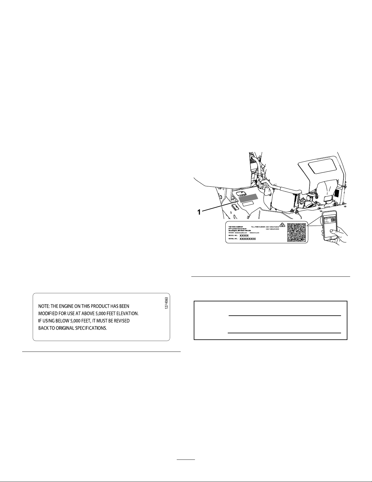
andserialnumbersofyourproductready.Figure1
identiesthelocationofthemodelandserialnumbers
ontheproduct.Writethenumbersinthespace
provided.
Important:Withyourmobiledevice,youcan
scantheQRcodeontheserialnumberdecal(if
equipped)toaccesswarranty,parts,andother
productinformation.
g234368
Figure1
1.Modelandserialnumberlocation
Writetheproductmodelandserialnumbersinthe
spacebelow:
decal127-9363
Introduction
Thisrotary-blade,ridinglawnmowerisintendedtobe
usedbyhomeownersinresidentialapplications.Itis
designedprimarilyforcuttinggrassonwell-maintained
lawns.
Readthisinformationcarefullytolearnhowtooperate
andmaintainyourproductproperlyandtoavoid
©2019—TheToro®Company
8111LyndaleAvenueSouth
Bloomington,MN55420
ModelNo.
SerialNo.
Thismanualuses2wordstohighlightinformation.
Importantcallsattentiontospecialmechanical
informationandNoteemphasizesgeneralinformation
worthyofspecialattention.
2
Contactusatwww.Toro.com.
PrintedintheUSA
AllRightsReserved
Page 3

Contents
Safety.......................................................................4
SafetyAlertSymbol............................................4
GeneralSafety...................................................4
SlopeIndicator...................................................5
SafetyandInstructionalDecals..........................6
ProductOverview...................................................14
Controls...........................................................14
BeforeOperation.................................................16
BeforeOperationSafety...................................16
Pre-Start...........................................................16
FuelSafety.......................................................17
AddingFuel......................................................18
PerformingDailyMaintenance..........................18
BreakinginaNewMachine..............................18
UsingtheSafety-InterlockSystem....................19
PositioningtheSeat..........................................19
AdjustingtheMyRide™Suspension
System..........................................................21
AdjustingtheMotion-ControlLevers.................22
DuringOperation.................................................23
DuringOperationSafety...................................23
OperatingtheMowerBlade-ControlSwitch
(PTO)............................................................25
OperatingtheThrottle.......................................25
OperatingtheChoke.........................................25
StartingtheEngine...........................................26
ShuttingOfftheEngine.....................................26
UsingtheMotion-ControlLevers.......................26
DrivingtheMachine..........................................27
UsingtheSideDischarge.................................28
AdjustingtheHeightofCut...............................29
AdjustingtheAnti-ScalpRollers........................29
UsingAttachmentsandAccessories.................30
OperatingTips.................................................30
AfterOperation....................................................31
AfterOperationSafety......................................31
PushingtheMachinebyHand..........................33
Maintenance...........................................................35
RecommendedMaintenanceSchedule(s)...........35
MaintenanceSafety..........................................35
Pre-MaintenanceProcedures..............................37
RaisingtheSeat...............................................37
Lubrication..........................................................37
GreasingtheBearings......................................37
EngineMaintenance...........................................38
EngineSafety...................................................38
ServicingtheAirCleaner..................................38
ServicingtheEngineOil....................................40
ServicingtheSparkPlug...................................42
CleaningtheCoolingSystem............................43
FuelSystemMaintenance...................................43
ReplacingtheIn-LineFuelFilter.......................43
ElectricalSystemMaintenance...........................44
ElectricalSystemSafety...................................44
ServicingtheBattery.........................................44
ServicingtheFuses..........................................46
DriveSystemMaintenance..................................46
CheckingtheTirePressure...............................46
ReleasingtheElectricBrake.............................47
BeltMaintenance................................................47
ReplacingtheMower-DeckBelt........................47
MowerMaintenance.............................................49
BladeSafety.....................................................49
ServicingtheCuttingBlades.............................49
LevelingtheMowerDeck..................................51
RemovingtheMowerDeck...............................53
InstallingtheMower..........................................54
ReplacingtheGrassDeector..........................55
ReplacingtheGrassDeector..........................56
Cleaning..............................................................57
WashingtheUndersideoftheMower
Deck..............................................................57
CleaningtheSuspensionSystem.....................57
DisposingofWaste...........................................57
Storage...................................................................58
StorageSafety..................................................58
CleaningandStorage.......................................58
StoringtheBattery............................................59
Troubleshooting......................................................60
Schematics.............................................................62
3
Page 4

Safety
ThefollowinginstructionsarefromANSIstandard
B71.1-2017.
SafetyAlertSymbol
ThisSafetyAlertSymbol(Figure3)isusedbothin
thismanualandonthemachinetoidentifyimportant
safetymessageswhichmustbefollowedtoavoid
accidents.
Thissymbolmeans:ATTENTION!BECOMEALERT!
YOURSAFETYISINVOL VED!
Figure3
SafetyAlertSymbol
GeneralSafety
Thismachineiscapableofamputatinghandsandfeet
andofthrowingobjects.T orodesignedandtested
thislawnmowertoofferreasonablysafeservice;
however,failuretocomplywithsafetyinstructions
mayresultininjuryordeath.
•Read,understand,andfollowallinstructionsand
warningsintheOperator’sManualandother
trainingmaterial,onthemachine,engine,and
attachments.Alloperatorsandmechanicsshould
betrained.Iftheoperator(s)ormechanic(s)can
notreadthismanual,itistheowner’sresponsibility
toexplainthismaterialtothem;otherlanguages
maybeavailableonourwebsite.
•Onlyallowtrained,responsible,andphysically
capableoperatorsthatarefamiliarwiththesafe
g000502
operation,operatorcontrols,andsafetysignsand
instructionstooperatethemachine.Neverlet
childrenoruntrainedpeopleoperateorservicethe
equipment.Localregulationsmayrestricttheage
oftheoperator.
Thesafetyalertsymbolappearsaboveinformation
whichalertsyoutounsafeactionsorsituationsand
willbefollowedbythewordDANGER,WARNING,or
CAUTION.
DANGER:Indicatesanimminentlyhazardous
situationwhich,ifnotavoided,Willresultindeathor
seriousinjury.
WARNING:Indicatesapotentiallyhazardoussituation
which,ifnotavoided,Couldresultindeathorserious
injury.
CAUTION:Indicatesapotentiallyhazardoussituation
which,ifnotavoided,Mayresultinminorormoderate
injury.
Thismanualusestwootherwordstohighlight
information.Importantcallsattentiontospecial
mechanicalinformationandNoteemphasizesgeneral
informationworthyofspecialattention.
•DoNotoperatethemachineneardrop-offs,
ditches,embankments,water,orotherhazards,or
onslopesgreaterthan15degrees.
•DoNotputyourhandsorfeetnearmoving
componentsofthemachine.
•Neveroperatethemachinewithdamagedguards,
shields,orcovers.Alwayshavesafetyshields,
guards,switchesandotherdevicesinplaceandin
properworkingcondition.
•Stopthemachine,shutofftheengine,andremove
thekeybeforeservicing,fueling,orunclogging
themachine.
4
Page 5
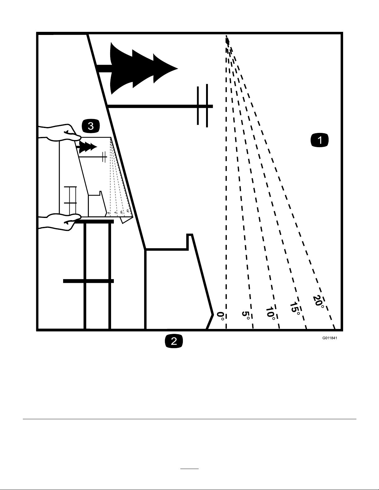
SlopeIndicator
Figure4
Youmaycopythispageforpersonaluse.
1.Themaximumslopeyoucanoperatethemachineonis15degrees.Usetheslopecharttodeterminethedegreeofslopeof
hillsbeforeoperating.Donotoperatethismachineonaslopegreaterthan15degrees.Foldalongtheappropriateline
tomatchtherecommendedslope.
2.Alignthisedgewithaverticalsurface,atree,building,fencepole,etc.
3.Exampleofhowtocompareslopewithfoldededge
5
g011841
Page 6
SafetyandInstructionalDecals
Safetydecalsandinstructionsareeasilyvisibletotheoperatorandarelocatednearanyarea
ofpotentialdanger.Replaceanydecalthatisdamagedormissing.
BatterySymbols
Someorallofthesesymbolsareonyourbattery .
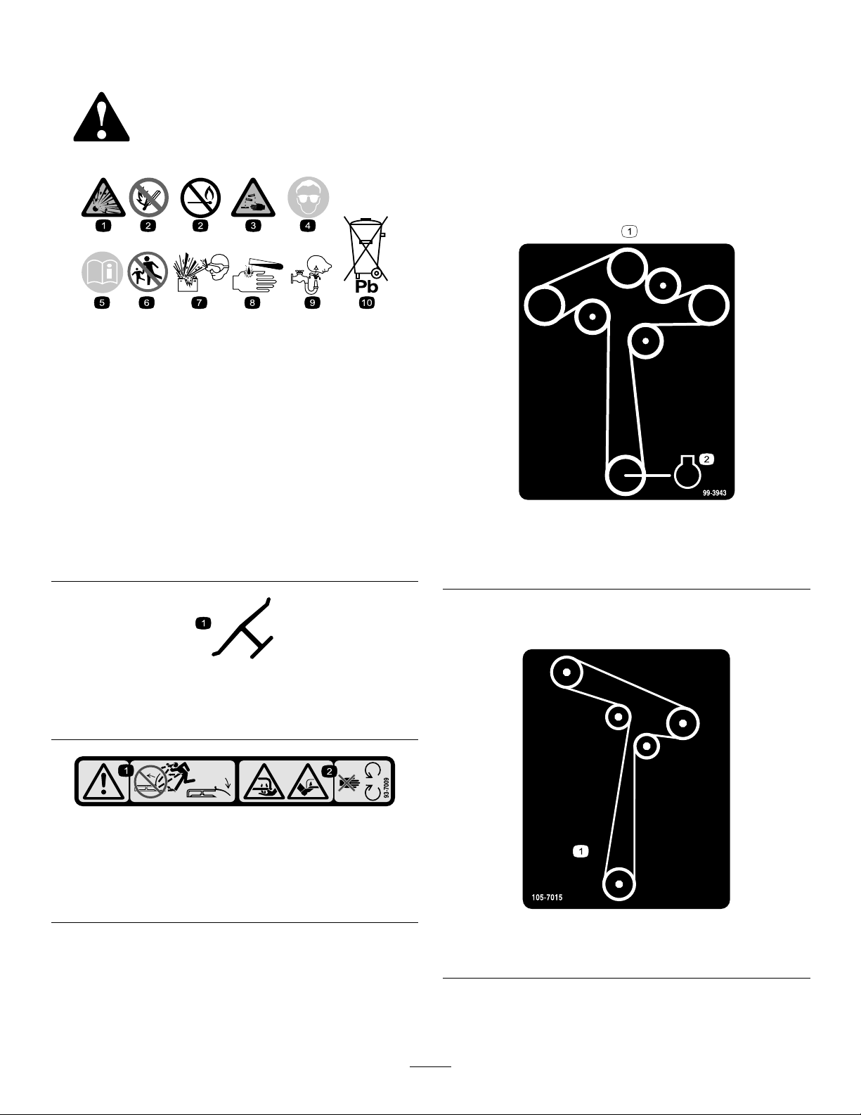
Decal99-3943isformodelswith127cm(50inch),
137cm(54inch),or152cm(60inch)decks.
decalbatterysymbols
1.Explosionhazard6.Keepbystandersaway
2.Nore,opename,or
smoking
3.Causticliquid/chemical
burnhazard
4.Weareyeprotection.9.Flusheyesimmediately
5.ReadtheOperator's
Manual.
fromthebattery .
7.Weareyeprotection;
explosivegasescan
causeblindnessandother
injuries.
8.Batteryacidcancause
blindnessorsevereburns.
withwaterandgetmedical
helpfast.
10.Containslead;donot
discard
Manufacturer'sMark
1.Indicatesthebladeisidentiedasapartfromtheoriginal
machinemanufacturer.
decal99-3943
99-3943
1.Beltrouting
2.Engine
Decal105-7015isformodelswith107cm(42-inch)
decks.
decaloemmarkt
93-7009
1.Warning—donotoperatethemowerwiththedeectorup
orremoved;keepthedeectorinplace.
2.Cutting/dismembermenthazardofhandorfoot,mower
blade—stayawayfrommovingparts.
decal93-7009
decal105-7015
105-7015
1.Beltrouting
6
Page 7

Decal106-8717isfornon-MyRidemodelswith107
cm(42inch),127cm(50inch),or137cm(54inch)
decks.
106-8717
1.Readtheinstructionsbeforeservicingorperforming
maintenance.
2.Checktirepressureevery25operatinghours.
3.Greaseevery25operatinghours.
4.Engine
Decal112-9840isformodelswith152cm(60inch)
mowerdecks.
decal119-8815
119-8815
decal106-8717
1.Parkingposition4.Neutral
2.Fast5.Reverse
3.Slow
Decal119-8870isforisformodelswith107cm(42
inch)mowerdecksortheMyRidesuspensionsystem.
112-9840
1.ReadtheOperator's
Manual.
2.Heightofcut
119-8814
1.Parkingposition4.Neutral
2.Fast5.Reverse
3.Slow
decal112-9840
3.Removetheignitionkey
andreadtheinstructions
beforeservicingor
performingmaintenance.
decal119-8870
119-8870
1.Heightofcut
decal119-8814
7
Page 8
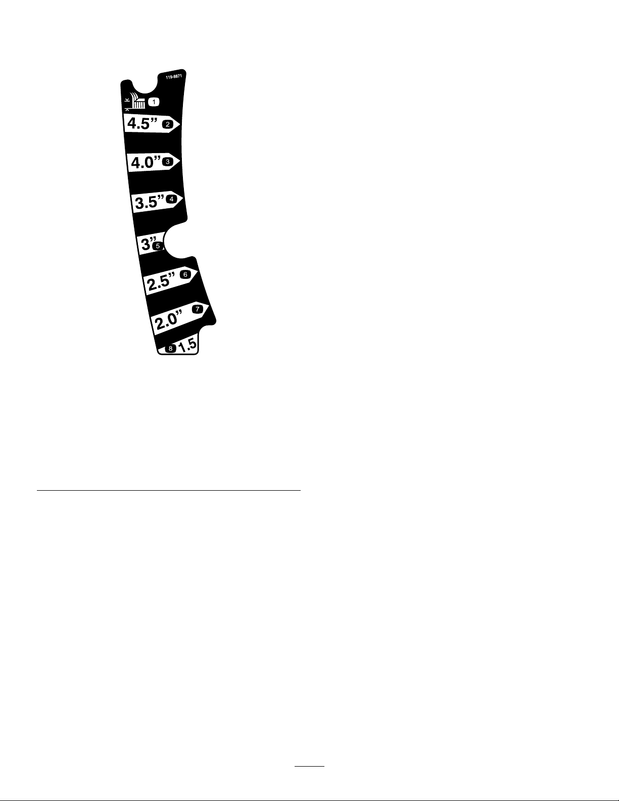
Decal119-8871isfornon-MyRidemodelswith127
cm(50inch),137cm(54inch),or152cm(60inch)
decks.
1.Heightofcut
2.4-1/2inches
3.4inches
4.3-1/2inches
5.3inches
6.2-1/2inches
7.2inches
8.1-1/2inches
decal119-8871
119-8871
8
Page 9

decal121-0772
121-0772
1.Fast
4.Choke
2.Continuousvariablesetting5.Powertake-off(PTO),Bladecontrolswitch
3.Slow
9
Page 10

decal131-1097
131-1097
decal121-2989b
1.Oildrain
121-2989
1.Bypassleverpositionfor
pushingthemachine
2.Bypassleverpositionfor
operatingthemachine
Decal131-3947doesnotapplytomodelswithouttheMyRidesuspensionsystemormodel74773.
131–3947
decal131-3947
1.Trim—slow
3.Mow—fast
2.Tow—medium
10
Page 11
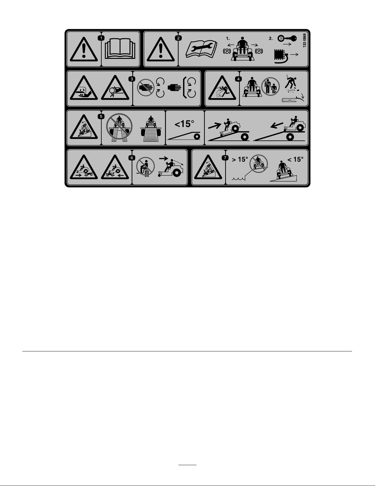
Decal132-0869isformodelswith107cm(42inch),127cm(50inch),or137cm(54inch)decks.
132-0869
Note:Thismachinecomplieswiththeindustrystandardstabilitytestinthestaticlateralandlongitudinaltestswiththemaximum
recommendedslopeindicatedonthedecal.ReviewtheinstructionsforoperatingthemachineonslopesintheOperator’sManualas
wellastheconditionsinwhichyouwouldoperatethemachinetodeterminewhetheryoucanoperatethemachineintheconditions
onthatdayandatthatsite.Changesintheterraincanresultinachangeinslopeoperationforthemachine.Ifpossible,keepthe
cuttingunitsloweredtothegroundwhileoperatingthemachineonslopes.Raisingthecuttingunitswhileoperatingonslopescan
causethemachinetobecomeunstable.
decal132-0869
1.Warning—readthe
Operator'sManual.
2.Warning—before
performingmaintenance,
readtheOperator'sManual;
engagetheparkingbrake,
removethekey ,and
disconnectthesparkplug.
3.Cutting/dismemberment
hazardofthehand,mower
blade;entanglement
hazardofthehand,
belt—stayawayfrom
movingparts;keepall
guardsandshieldsinplace.
4.Thrownobject
hazard—keepbystanders
away;pickupdebris
beforeoperating;lowerthe
deectorbeforeusingthe
machine.
5.Ramphazard—donot
usedualrampswhen
loadingontoatrailer;use
1rampwideenoughfor
themachine;usearamp
withaslopelessthan15°;
backuptherampwhen
loadingthemachineand
driveforwardofftheramp
whenunloading.
6.Runover/backover
hazard—donotcarry
passengers;lookbehind
youwhenmowingin
reverse.
7.Tippinghazard—donot
useonslopesnearopen
water;donotuseonslopes
greaterthan15°.
11
Page 12

decal132-0872
132-0872
1.Thrownobject
hazard—keepbystanders
awayfromthemachine.
2.Thrownobjecthazard,
raisedbafe—donot
operatethemachinewith
anopendeck;usea
baggerorabafe.
3.Severinghazardofhand
orfoot—keepawayfrom
movingparts.
4.Entanglement
hazard—keepaway
frommovingparts;keep
allguardsandshieldsin
place.
133-9255
Note:Thismachinecomplieswiththeindustrystandardstabilitytestinthestaticlateralandlongitudinaltestswiththemaximum
recommendedslopeindicatedonthedecal.ReviewtheinstructionsforoperatingthemachineonslopesintheOperator’sManualas
wellastheconditionsinwhichyouwouldoperatethemachinetodeterminewhetheryoucanoperatethemachineintheconditions
onthatdayandatthatsite.Changesintheterraincanresultinachangeinslopeoperationforthemachine.Ifpossible,keepthe
cuttingunitsloweredtothegroundwhileoperatingthemachineonslopes.Raisingthecuttingunitswhileoperatingonslopescan
causethemachinetobecomeunstable.
decal133-9255
1.Warning—readtheOperator'sManual.
2.Ramphazard—donotusedualrampswhenloadingontoa
trailer;use1rampwideenoughforthemachine;usearamp
withaslopelessthan15°;backuptherampwhenloadingthe
machineanddriveforwardofftherampwhenunloading.
3.Thrownobjecthazard—keepbystandersaway;pickup
debrisbeforeoperating;lowerthedeectorbeforeusingthe
machine.
4.Runover/backoverhazard—donotcarrypassengers;look
behindyouwhenmowinginreverse.
5.Tippinghazard—donotuseonslopesnearopenwater;do
notuseonslopesgreaterthan15°.
6.Cutting/dismembermenthazardofthehand,mowerblade;
entanglementhazardofthehand,belt—stayawayfrom
movingparts;keepallguardsandshieldsinplace.
7.Warning—beforeperformingmaintenance,readthe
Operator'sManual;engagetheparkingbrake,removethe
key,anddisconnectthesparkplug.
12
Page 13

Decal136-4245isformodelswiththeMyRide
suspensionsystem.
Decal136-5596isformodelswiththeMyRide
suspensionsystemor152cm(60inch)decks.
decal136-5596
136-5596
decal136-4245
136-4245
1.Slow
2.Transport
3.Fast
Decal137-7044isformodelswiththeMyRidesuspensionsystem.
1.Checkthetirepressure
every25operatinghours.
2.Engineoil
4.Checkthetirepressure
every25operatinghours.
5.ReadtheOperator's
Manualbeforeperforming
maintenance.
3.Checkthetirepressure
every25operatinghours.
Decal136-9186isformodelswith152cm(60inch)
decks.
136-9186
1.ReadtheOperator'sManualbeforeaddingweighttothe
bucket.
decal136-9186
137-7044
1.Camlock2.Camunlock
decal138-2456
138-2456
1.ReadtheOperator’s
Manual.
2.Parkthemachineona
levelsurfacewhenlling
thefueltank.
3.Donotoverllthefuel
tank.
13
decal137-7044
Page 14
ProductOverview
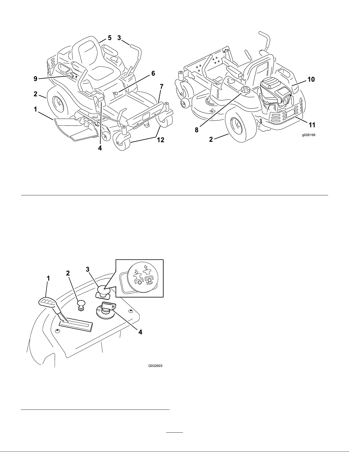
g028166
Figure5
1.Deector4.Height-of-cutlever
2.Reardrivewheel
3.Motion-controllevers
5.Operatorseat
6.SmartSpeed™lever9.Controlpanel
Controls
Becomefamiliarwithallthecontrolsbeforeyoustart
theengineandoperatethemachine.
ControlPanel
7.Footrest10.Engine
8.Fuel-tankcap11.Engineguard
12.Frontcasterwheel
KeySwitch
Thekeyswitch,usedtostartandshutofftheengine,
has3positions:OFF,RUN,andST ART.Referto
StartingtheEngine(page26).
ThrottleControl
Thethrottlecontrolstheenginespeed,andithasa
continuous-variablesettingfromtheSLOWtoFAST
position(Figure6).
ChokeControl
Usethechokecontroltostartacoldengine.
Blade-ControlSwitch(Power
Figure6
1.Throttlecontrol3.Blade-controlswitch
2.Chokecontrol
(powertakeoff)
4.Keyswitch
Takeoff)
Theblade-controlswitch,representedbya
power-takeoff(PTO)symbol,engagesand
g032603
disengagespowertothemowerblades(Figure6).
14
Page 15
Motion-ControlLevers
Height-of-CutLever
Usethemotion-controlleverstodrivethemachine
forward,reverse,andturneitherdirection(Figure5).
ParkPosition
Movethemotion-controlleversoutwardfromthe
centertothePARKpositionwhenexitingthemachine
(Figure24).Alwayspositionthemotion-controllevers
intothePARKpositionwhenyoustopthemachineor
leaveitunattended.
SmartSpeed™ControlSystem
Lever
TheSmartSpeed™Control-Systemlever,located
belowtheoperatingposition,givesyouachoiceto
drivethemachineat3speedranges—trim,tow,and
mow(Figure27).
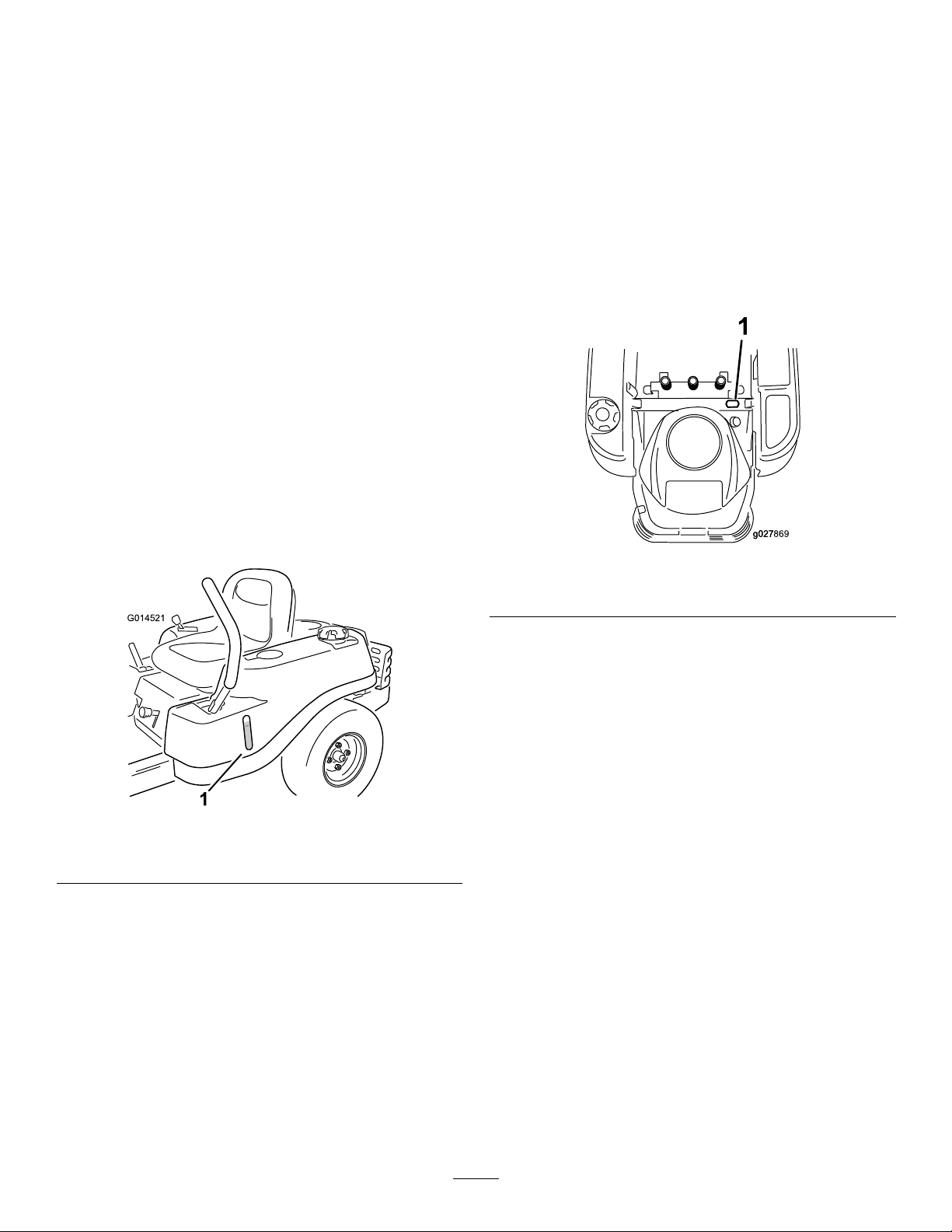
Fuel-PresenceWindow
Youcanusethefuelwindow,locatedontheleftside
ofthemachine,toverifythepresenceoffuelinthe
tank(Figure7).
Usetheheight-of-cutlevertolowerandraisethedeck
fromtheseatedposition.Movingtheleverup(toward
you)raisesthedeckfromthegroundandmovingthe
leverdown(awayfromyou)lowersthedecktoward
theground.Adjusttheheight-of-cutonlywhilethe
machineisnotmoving(Figure29).
HourMeter(IfEquipped)
Thehourmeterrecordsthenumberofhourswhen
youareintheseatandthekeyswitchisintheON
position(Figure8).
g027869
Figure8
1.Fuel-presencewindow
Figure7
1.Thehourmeterislocatedbehindtheseat.
Attachments/Accessories
AselectionofT oroapprovedattachmentsand
accessoriesisavailableforusewiththemachine
toenhanceandexpanditscapabilities.Contact
yourAuthorizedServiceDealerorauthorizedT oro
distributororgotowww.Toro.comforalistofall
approvedattachmentsandaccessories.
g014521
Toensureoptimumperformanceandcontinuedsafety
certicationofthemachine,useonlygenuineT oro
replacementpartsandaccessories.Replacement
partsandaccessoriesmadebyothermanufacturers
couldbedangerous,andsuchusecouldvoidthe
productwarranty.
15
Page 16

Operation
Note:Determinetheleftandrightsidesofthe
machinefromthenormaloperatingposition.
Pre-Start
Fillfueltankonlevelground.SeeFuel
RecommendationsintheSpecicationssectionfor
additionalgasolineinformation.
DoNotaddoiltogasoline.
BeforeOperation
BeforeOperationSafety
•Evaluatetheterraintodeterminewhataccessories
andattachmentsareneededtoproperlyand
safelyperformthejob.Onlyuseaccessoriesand
attachmentsapprovedbyToro.
•Inspecttheareawheretheequipmentistobe
usedandremoveallrocks,toys,sticks,wires,
bones,andotherforeignobjects.Thesecan
bethrownorinterferewiththeoperationofthe
machineandmaycausepersonalinjurytothe
operatororbystanders.
•Wearappropriatepersonalprotectiveequipment
suchassafetyglasses,substantialslip-resistant
footwear,andhearingprotection.Tiebacklong
hairandavoidlooseclothingandloosejewelry
whichmaygettangledinmovingparts.
CAUTION
Thismachineproducessoundlevelsin
excessof85dBAattheoperator’searand
cancausehearinglossthroughextended
periodsofexposure.
DoNotoverllfueltank.Fillthefueltanktothebottom
ofthellerneck.Theemptyspaceinthetankallows
gasolinetoexpand.Overllingmayresultinfuel
leakageordamagetotheengineoremissionsystem.
Makesureyouunderstandthecontrols,theirlocations,
theirfunctions,andtheirsafetyrequirements.
RefertotheMaintenancesectionandperformallthe
necessaryinspectionandmaintenancesteps.
Wearhearingprotectionwhenoperating
thismachine.
•Checkthattheoperatorpresencecontrols,
safetyswitches,andshieldsareattachedand
functioningproperly.DoNotoperateunlessthey
arefunctioningproperly.
•DoNotoperatethemowerwhenpeople,especially
children,orpetsareinthearea.Stopthemachine
andattachment(s)ifanyoneentersthearea.
•DoNotoperatethemachinewithouttheentire
grasscollectionsystem,dischargedeector,
orothersafetydevicesinplaceandinproper
workingcondition.Grasscatchercomponents
aresubjecttowear,damageanddeterioration,
whichcouldexposemovingpartsorallowobjects
tobethrown.Frequentlycheckforwornor
deterioratingcomponentsandreplacethemwith
themanufacturer’srecommendedpartswhen
necessary.
16
Page 17

FuelSafety
DANGER
Useextremecarewhenhandlingfuel.
DANGER
Incertainconditionsgasolineisextremely
ammableandvaporsareexplosive.
Areorexplosionfromgasolinecanburn
you,others,andcausepropertydamage.
•Fillthefueltankoutdoorsonlevelground,
inanopenarea,whentheengineiscold.
Wipeupanygasolinethatspills.
•Neverrellthefueltankordrainthe
machineindoorsorinsideanenclosed
trailer.
•DoNotllthefueltankcompletelyfull.
Fillthefueltanktothebottomoftheller
neck.Theemptyspaceinthetankallows
gasolinetoexpand.Overllingmayresult
infuelleakageordamagetotheengineor
emissionsystem.
•Neversmokewhenhandlinggasoline,and
stayawayfromanopenameorwhere
gasolinefumesmaybeignitedbyspark.
•Storegasolineinanapprovedcontainer
andkeepitoutofthereachofchildren.
Incertainconditionsduringfueling,static
electricitycanbereleasedcausingaspark
whichcanignitegasolinevapors.Areor
explosionfromgasolinecanburnyouand
othersandcausepropertydamage.
•Alwaysplacegasolinecontainersonthe
groundawayfromyourvehiclebefore
lling.
•DoNotllgasolinecontainersinsidea
vehicleoronatruckortrailerbedbecause
interiorcarpetsorplastictruckbedliners
mayinsulatethecontainerandslowthe
lossofanystaticcharge.
•Whenpractical,removegas-powered
equipmentfromthetruckortrailerand
refueltheequipmentwithitswheelsonthe
ground.
•Ifthisisnotpossible,thenrefuelsuch
equipmentonatruckortrailerfroma
portablecontainer,ratherthanfroma
gasolinedispensernozzle.
•Ifagasolinedispensernozzlemustbe
used,keepthenozzleincontactwiththe
rimofthefueltankorcontaineropeningat
alltimesuntilfuelingiscomplete.DoNot
useanozzlelockopendevice.
•Addfuelbeforestartingtheengine.Never
removethecapofthefueltankoraddfuel
whenengineisrunningorwhentheengine
ishot.
•Iffuelisspilled,DoNotattempttostart
theengine.Moveawayfromtheareaof
thespillandavoidcreatinganysourceof
ignitionuntilfuelvaporshavedissipated.
•DoNotoperatewithoutentireexhaust
systeminplaceandinproperworking
condition.
WARNING
Gasolineisharmfulorfatalifswallowed.
Long-termexposuretovaporshascaused
cancerinlaboratoryanimals.Failuretouse
cautionmaycauseseriousinjuryorillness.
•Avoidprolongedbreathingofvapors.
•Keepfaceawayfromnozzleandgas
tank/containeropening.
•Keepawayfromeyesandskin.
•Neversiphonbymouth.
Tohelppreventres:
•Keepengineandengineareafreefrom
accumulationofgrass,leaves,excessivegrease
oroil,andotherdebriswhichcanaccumulatein
theseareas.
•Cleanupoilandfuelspillsandremovefuelsoaked
debris.
•Allowthemachinetocoolbeforestoringthe
machineinanyenclosure.DoNotstorenear
ameoranyenclosedareawhereopenpilotlights
orheatappliancesarepresent.
17
Page 18
AddingFuel
RecommendedFuel
•Forbestresults,useonlyclean,fresh(lessthan
30daysold),unleadedgasolinewithanoctane
ratingof87orhigher((R+M)/2ratingmethod).
•Ethanol:Gasolinewithupto10%ethanol
(gasohol)or15%MTBE(methyltertiarybutyl
ether)byvolumeisacceptable.Ethanoland
MTBEarenotthesame.Gasolinewith15%
ethanol(E15)byvolumeisnotapprovedforuse.
Neverusegasolinethatcontainsmorethan
10%ethanolbyvolume,suchasE15(contains
15%ethanol),E20(contains20%ethanol),orE85
(containsupto85%ethanol).Usingunapproved
gasolinemaycauseperformanceproblemsand/or
enginedamagewhichmaynotbecoveredunder
warranty.
•Donotusegasolinecontainingmethanol.
•Donotstorefueleitherinthefueltankorfuel
containersoverthewinterunlessyouuseafuel
stabilizer.
Note:Donotllthefueltankcompletelyfull.
Theemptyspaceinthetankallowsthefuelto
expand.
•Donotaddoiltogasoline.
UsingStabilizer/Conditioner
Useafuelstabilizer/conditionerinthemachineto
providethefollowingbenets:
•Keepsfuelfreshlongerwhenusedasdirectedby
thefuel-stabilizermanufacturer
•Cleanstheenginewhileitruns
•Eliminatesgum-likevarnishbuildupinthefuel
system,whichcauseshardstarting
Important:Donotusefueladditives
containingmethanolorethanol.
Addthecorrectamountoffuelstabilizer/conditioner
tothefuel.
Note:Afuelstabilizer/conditionerismost
effectivewhenmixedwithfreshfuel.T ominimize
thechanceofvarnishdepositsinthefuelsystem,
usefuelstabilizeratalltimes.
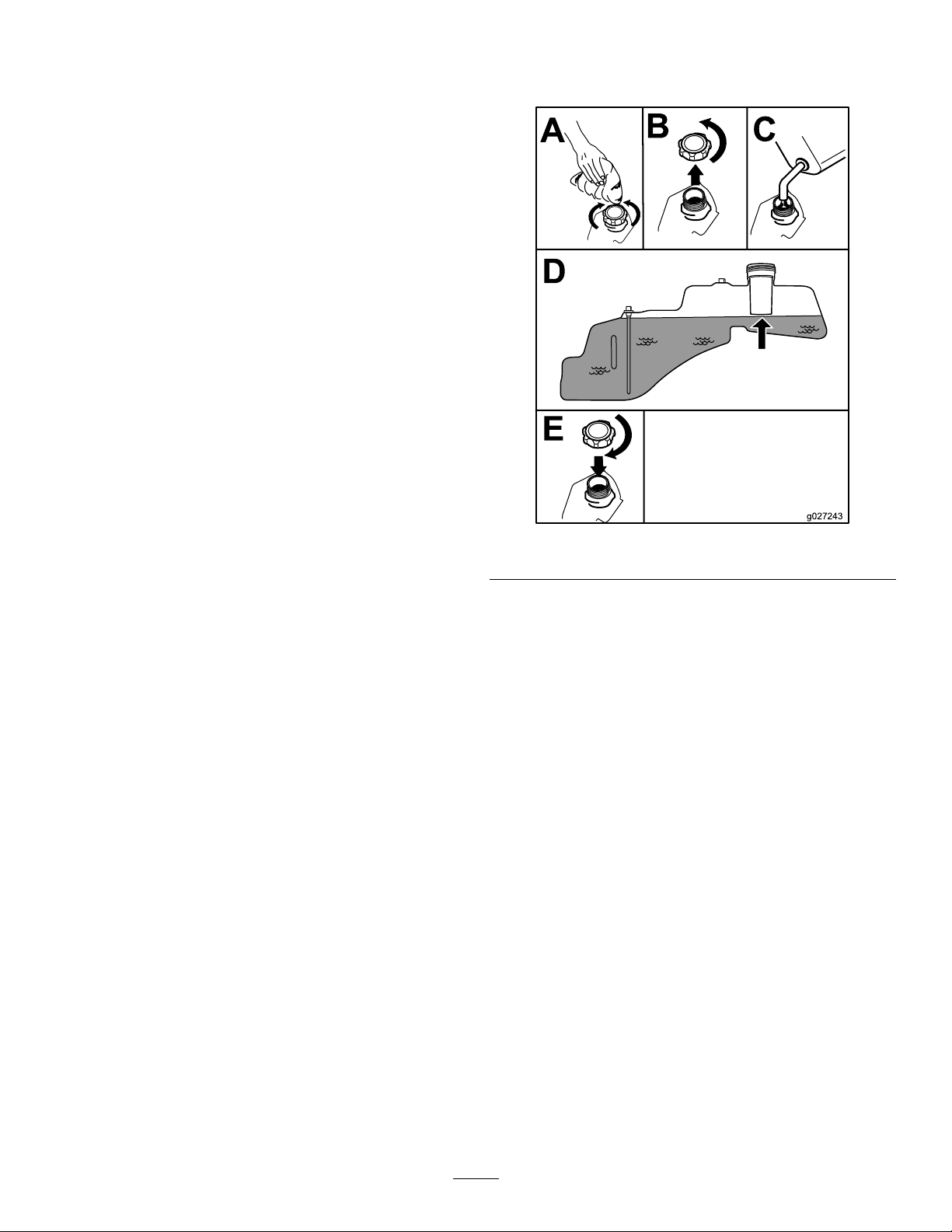
g027243
Figure9
PerformingDaily
Maintenance
Beforestartingthemachineeachday ,performthe
EachUse/DailyprocedureslistedinMaintenance
(page35).
BreakinginaNewMachine
Newenginestaketimetodevelopfullpower.Mower
decksanddrivesystemshavehigherfrictionwhen
new,placingadditionalloadontheengine.Allow
40to50hoursofbreak-intimefornewmachinesto
developfullpowerandbestperformance.
FillingtheFuelTank
1.Parkthemachineonalevelsurface.
2.Engagetheparkingbrake.
3.Shutofftheengineandremovethekey.
4.Cleanaroundthefuel-tankcap.
5.Fillthefueltanktothebottomofthellerneck
(Figure9).
18
Page 19
UsingtheSafety-Interlock
System
WARNING
Ifthesafety-interlockswitchesare
disconnectedordamaged,themachinecould
operateunexpectedly,causingpersonal
injury.
•Donottamperwiththeinterlockswitches.
•Checktheoperationoftheinterlock
switchesdailyandreplaceanydamaged
switchesbeforeoperatingthemachine.
Understandingthe
Safety-InterlockSystem
Thesafety-interlocksystemisdesignedtopreventthe
enginefromstartingunless:
•Theblade-controlswitch(PTO)isdisengaged.
motion-controlleverstothecenter,unlocked
position,engagetheblade-controlswitch,and
riseslightlyfromtheseat;theengineshould
shutoff.
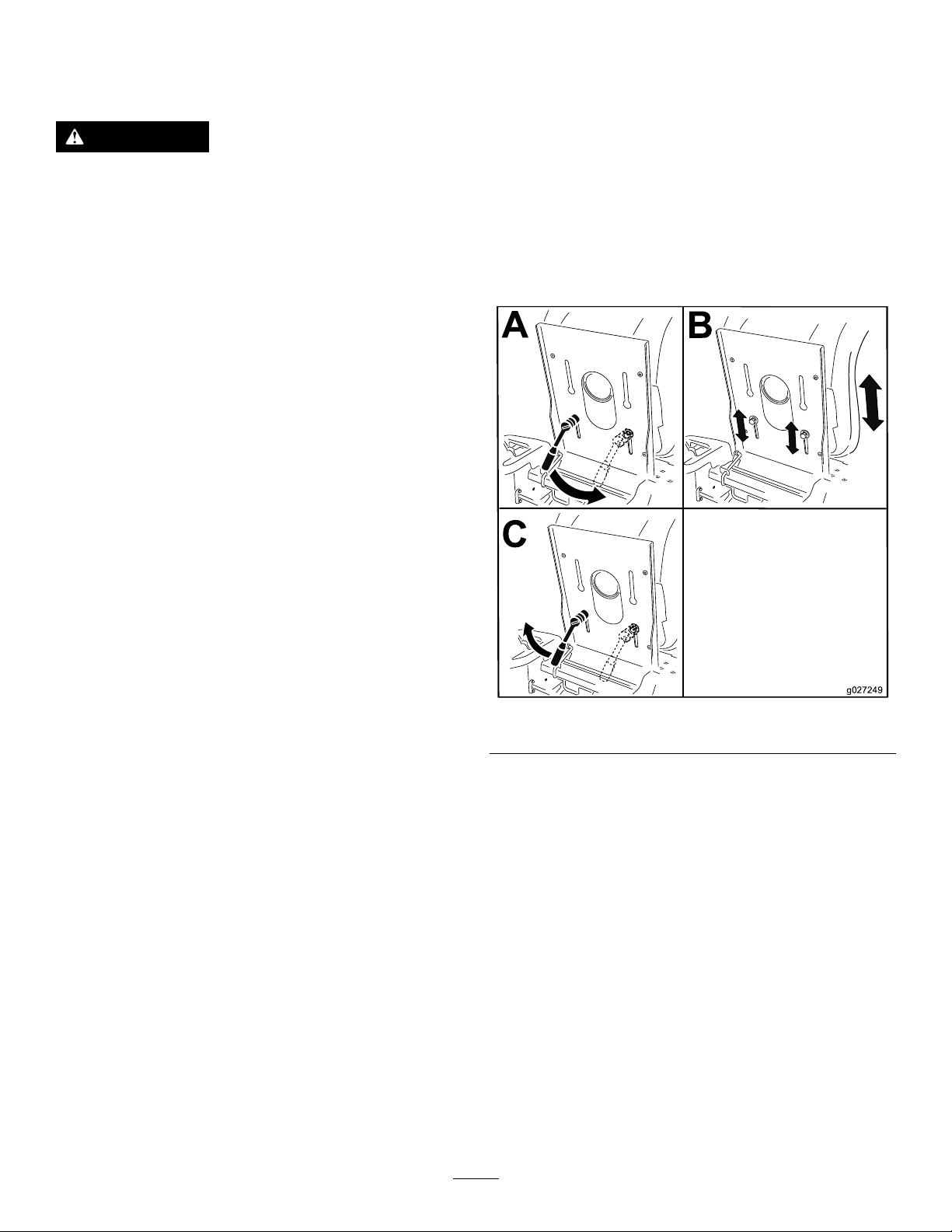
PositioningtheSeat
ForModels74726and74766
Theseatcanmoveforwardandbackward.Position
theseatwhereyouhavethebestcontrolofthe
machineandaremostcomfortable(Figure10).
•Themotion-controlleversareinthePARKposition.
Thesafety-interlocksystemalsoisdesignedtoshut
offtheenginewheneverthecontrolleversareoutof
thePARKpositionandyourisefromtheseat.
TestingtheSafety-Interlock
System
Testthesafety-interlocksystembeforeyouusethe
machineeachtime.Ifthesafetysystemdoesnot
operateasdescribedbelow,haveanAuthorized
ServiceDealerrepairthesafetysystemimmediately .
1.Sitontheseat,movethemotion-controllevers
inthePARKposition,andmovetheblade-control
switchtotheONposition.Trystartingthe
engine;theengineshouldnotcrank.
2.Sitontheseatandmovetheblade-controlswitch
totheOFFposition.Moveeithermotion-control
levertothecenter,unlockedposition.Try
startingtheengine;theengineshouldnotcrank.
Repeatwiththeothermotion-controllever.
3.Sitontheseat,movetheblade-controlswitch
totheOFFposition,andlockthemotion-control
leversinthePARKposition.Starttheengine.
Whiletheengineisrunning,engagethe
blade-controlswitch,andriseslightlyfromthe
seat;theengineshouldshutoff.
g027249
Figure10
4.Sitontheseat,movetheblade-controlswitch
totheOFFposition,andlockthemotion-control
leversinthePARKposition.Starttheengine.
Whiletheengineisrunning,movethe
19
Page 20
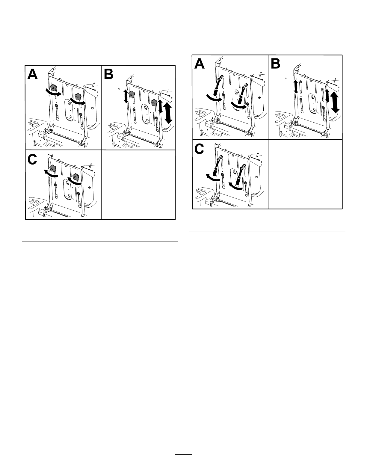
ForModels74760,74774,and
ForModels74772and74773
74777
Theseatcanmoveforwardandbackward.Position
theseatwhereyouhavethebestcontrolofthe
machineandaremostcomfortable(Figure11).
Theseatcanmoveforwardandbackward.Position
theseatwhereyouhavethebestcontrolofthe
machineandaremostcomfortable(Figure12).
Figure11
g265989
g265992
Figure12
20
Page 21

ForModels74768and74778
AdjustingtheMyRide™
Theseatcanmoveforwardandbackward.Position
theseatwhereyouhavethebestcontrolofthe
machineandaremostcomfortable(Figure13).
Figure13
SuspensionSystem
ForMachineswiththeMyRide™
SuspensionSystem
Note:T omakeadjustingtheMyRide™suspension
systemeasier,pivottheseatforwardandinstallthe
proprodtotakeweightofftheshockassemblies.
TheMyRide™suspensionsystemadjuststoprovide
asmoothandcomfortableride.Youcanadjustthe
rear2-shockassembliestoquicklyandeasilychange
thesuspensionsystem.Positionthesuspension
systemwhereyouaremostcomfortable.
AdjustingtheRear-Shock
Assemblies
g027632
Theslotsfortherear-shockassemblieshavedetent
positionsforreference.
Thefollowinggraphicshowsthepositionforasoftor
rmrideandthedifferentdetentpositions(Figure14).
Figure14
1.Firmestposition3.Detentsintheslots
2.Softestposition
Note:Ensurethattheleftandrightrear-shock
assembliesarealwaysadjustedtothesamepositions.
Adjusttherear-shockassemblies(Figure15).
21
g231347
Page 22

Adjustingthe
Motion-ControlLevers
AdjustingtheHeight
Youcanadjustthemotion-controllevershigheror
lowerformaximumcomfort(Figure16).
Figure16
g027252
Figure15
AdjustingtheTilt
Youcanadjustthemotion-controlleversforwardor
rearwardforyourcomfort.
1.Loosentheupperboltholdingthecontrollever
tothecontrol-armshaft.
2.Loosenthelowerboltjustenoughtopivotthe
controlleverforwardorrearward(Figure16).
3.Tightenbothboltstosecurethecontrolleverin
g231392
thenewposition.
4.Repeattheadjustmentfortheothercontrollever.
22
Page 23

DuringOperation
DuringOperationSafety
GeneralSafety
Theoperatormustusetheirfullattentionwhen
operatingthemachine.DoNotengageinanyactivity
thatcausesdistractions;otherwise,injuryorproperty
damagemayoccur.
WARNING
Operatingengineparts,especiallythemufer,
becomeextremelyhot.Severeburnscan
occuroncontactanddebris,suchasleaves,
grass,brush,etc.cancatchre.
•Allowengineparts,especiallythemufer,
tocoolbeforetouching.
•Removeaccumulateddebrisfrommufer
andenginearea.
WARNING
Engineexhaustcontainscarbonmonoxide,
whichisanodorlessdeadlypoisonthatcan
killyou.
DoNotrunengineindoorsorinasmall
connedareawheredangerouscarbon
monoxidefumescancollect.
•Theowner/usercanpreventandisresponsible
foraccidentsorinjuriesoccurringtohimselfor
herself,otherpeopleorproperty .
•Thismowerwasdesignedforoneoperatoronly .
Donotcarrypassengersandkeepallothersaway
frommachineduringoperation.
•DoNotoperatethemachineundertheinuence
ofalcoholordrugs.
•Operateonlyindaylightorgoodarticiallight.
•Lightningcancausesevereinjuryordeath.If
lightningisseenorthunderisheardinthearea,
DoNotoperatethemachine;seekshelter.
•Useextracarewhileoperatingwithaccessoriesor
attachments,suchasgrasscollectionsystems.
Thesecanchangethestabilityofthemachine
andcausealossofcontrol.Followdirectionsfor
counterweightsifrequired.
•Keepawayfromholes,ruts,bumps,rocks,and
otherhiddenhazards.Usecarewhenapproaching
blindcorners,shrubs,trees,tallgrassorother
objectsthatmayhideobstaclesorobscurevision.
Uneventerraincouldoverturnthemachineor
causetheoperatortolosetheirbalanceorfooting.
•Besurealldrivesareinneutralandparkingbrake
isengagedbeforestartingengine.
•Starttheenginecarefullyaccordingtoinstructions
withfeetwellawayfromtheblades.
•Neveroperatethemowerwithdamagedguards,
shields,orcovers.Alwayshavesafetyshields,
guards,switchesandotherdevicesinplaceandin
properworkingcondition.
•Keepclearofthedischargeopeningatalltimes.
Nevermowwiththedischargedoorraised,
removedoralteredunlessthereisagrass
collectionsystemormulchkitinplaceandworking
properly.
•Keephandsandfeetawayfrommovingparts.
Ifpossible,DoNotmakeadjustmentswiththe
enginerunning.
WARNING
Hands,feet,hair,clothing,oraccessories
canbecomeentangledinrotatingparts.
Contactwiththerotatingpartscan
causetraumaticamputationorsevere
lacerations.
–DoNotoperatethemachinewithout
guards,shields,andsafetydevicesin
placeandworkingproperly .
–Keephands,feet,hair,jewelry,or
clothingawayfromrotatingparts.
•Neverraisethedeckwithbladesrunning.
•Beawareofthemowerdischargepathanddirect
dischargeawayfromothers.Avoiddischarging
materialagainstawallorobstructionasthe
materialmayricochetbacktowardtheoperator.
Stoptheblades,slowdown,andusecautionwhen
crossingsurfacesotherthangrassandwhen
transportingthemowertoandfromtheareatobe
mowed.
•Bealert,slowdownandusecautionwhen
makingturns.Lookbehindandtothesidebefore
changingdirections.DoNotmowinreverse
unlessabsolutelynecessary.
•DoNotchangetheenginegovernorsettingor
overspeedtheengine.
•Parkthemachineonlevelground.Stopengine,
waitforallmovingpartstostop,andremovethe
sparkplugwire(s).
–Beforechecking,cleaningorworkingonthe
mower.
–Afterstrikingaforeignobjectorabnormal
vibrationoccurs(inspectthemowerfor
damageandmakerepairsbeforerestarting
andoperatingthemower).
–Beforeclearingblockages.
23
Page 24

–Wheneveryouleavethemower.DoNotleave
arunningmachineunattended.
•Stopengine,waitforallmovingpartstostop:
–Beforerefueling.
–Beforedumpingthegrasscatcher.
–Beforemakingheightadjustments.
•Tragicaccidentscanoccuriftheoperatorisnot
alerttothepresenceofchildren.Childrenare
oftenattractedtothemachineandthemowing
activity.Neverassumethatchildrenwillremain
whereyoulastsawthem.
–Keepchildrenoutofthemowingareaand
underthewatchfulcareofanotherresponsible
adult,nottheoperator.
–Bealertandturnthemachineoffifchildren
enterthearea.
–Beforeandwhilebackingorchangingdirection,
lookbehind,down,andside-to-sideforsmall
children.
–Neverallowchildrentooperatethemachine.
–DoNotcarrychildren,evenwiththeblades
shutoff.Childrencouldfalloffandbeseriously
injuredorinterferewiththesafeoperationof
themachine.Childrenthathavebeengiven
ridesinthepastcouldsuddenlyappearinthe
workingareaforanotherrideandberunover
orbackedoverbythemachine.
distance(twicethewidthofthemachine)between
themachineandanyhazard.Useawalkbehind
machineorahandtrimmertomowthegrassin
theseareas.
g22911 1
Figure17
1.SafeZone-Usethemowerhereonslopeslessthan15
degrees
2.DangerZone-Useawalk-behindmowerand/orhand
trimmeronslopesgreaterthan15degrees
3.Water
4.W=widthofthemachine
5.Keepasafedistance(twicethewidthofthemachine)
betweenthemachineandanyhazard.
SlopeSafety
•Slopesareamajorfactorrelatedtolossofcontrol
androlloveraccidents,whichcanresultinsevere
injuryordeath.Theoperatorisresponsiblefor
safeslopeoperation.Operatingthemachineon
anysloperequiresextracaution.Beforeusingthe
machineonaslope,theoperatormust:
–Reviewandunderstandtheslopeinstructions
inthemanualandonthemachine.
–Useanangleindicatortodeterminethe
approximateslopeangleofthearea.
–Neveroperateonslopesgreaterthan15
degrees.
–Evaluatethesiteconditionsofthedayto
determineiftheslopeissafeformachine
operation.Usecommonsenseandgood
judgmentwhenperformingthisevaluation.
Changesintheterrain,suchasmoisture,can
quicklyaffecttheoperationofthemachineon
aslope.
•Identifyhazardsatthebaseoftheslope.Do
Notoperatethemachineneardropoffs,ditches,
embankments,waterorotherhazards.The
machinecouldsuddenlyrolloverifawheelgoes
overtheedgeortheedgecollapses.Keepasafe
•Avoidstarting,stoppingorturningthemachineon
slopes.Avoidmakingsuddenchangesinspeedor
direction;turnslowlyandgradually .
•DoNotoperateamachineunderanyconditions
wheretraction,steeringorstabilityisinquestion.
Beawarethatoperatingthemachineonwet
grass,acrossslopesordownhillmaycausethe
machinetolosetraction.Lossoftractiontothe
drivewheelsmayresultinslidingandalossof
brakingandsteering.Themachinecanslideeven
ifthedrivewheelsarestopped.
•Removeormarkobstaclessuchasditches,holes,
ruts,bumps,rocksorotherhiddenhazards.Tall
grasscanhideobstacles.Uneventerraincould
overturnthemachine.
•Useextracarewhileoperatingwithaccessoriesor
attachments,suchasgrasscollectionsystems.
Thesecanchangethestabilityofthemachine
andcausealossofcontrol.Followdirectionsfor
counterweights.
•Ifpossible,keepthedeckloweredtotheground
whileoperatingonslopes.Raisingthedeckwhile
operatingonslopescancausethemachineto
becomeunstable.
24
Page 25

OperatingtheMower
OperatingtheThrottle
Blade-ControlSwitch(PTO)
Theblade-controlswitch(PTO)startsandstopsthe
mowerbladesandanypoweredattachments.
EngagingtheBlade-Control
Switch(PTO)
Figure18
Note:Alwaysengagethebladeswiththethrottlein
theFASTposition(Figure19).
YoucanmovethethrottlecontrolbetweenFASTand
SLOWpositions(Figure21).
AlwaysusetheFASTpositionwhenengagingthePTO.
g187517
Figure21
g008945
OperatingtheChoke
Usethechoketostartacoldengine.
1.Pullupthechokeknobtoengagethechoke
beforeusingthekeyswitch(Figure22).
DisengagingtheBlade-Control
Switch(PTO)
Note:Ensurethatyoufullyengagethechoke.
Youmayneedtoholdtheknobupwhenyou
usethekeyswitch.
2.Pushdownthechoketodisengagethechoke
aftertheenginehasstarted(Figure22).
g187516
Figure19
Figure20
g009174
Figure22
1.ONposition2.OFFposition
25
g008959
Page 26

StartingtheEngine
ShuttingOfftheEngine
Note:Awarmorhotenginemaynotrequirechoking.
Important:Donotengagethestarterformore
than5secondsatatime.Engagingthestarter
motorformorethan5secondscandamagethe
startermotor.Iftheenginefailstostart,wait10
secondsbeforeoperatingtheenginestarteragain.
1.Disengagethebladesbymovingthe
blade-controlswitchtotheOFFposition(Figure
23).
2.Engagetheparkingbrake;refertoParkPosition
(page15).
3.MovethethrottlecontroltotheFASTposition.
4.TurnthekeytotheOFFpositionandremove
thekey .
CAUTION
Childrenorbystandersmaybeinjuredifthey
moveorattempttooperatethemachinewhile
itisunattended.
Alwaysremovethekeyandengagethe
parkingbrakewhenleavingthemachine
unattended.
UsingtheMotion-Control
Levers
Figure23
g027581
g004532
Figure24
1.Motion-control
lever—PARKposition
2.Center,unlockedposition5.Frontofmachine
3.Forward
26
4.Backward
Page 27

DrivingtheMachine
Thedrivewheelsturnindependently,poweredby
hydraulicmotorsoneachaxle.Youcanturn1side
inreversewhileyouturntheotherforward,causing
themachinetospinratherthanturn.Thisgreatly
improvesthemachinemaneuverabilitybutmay
requiresometimeforyoutoadapttohowitmoves.
Thethrottlecontrolregulatestheenginespeedas
measuredinrpm(revolutionsperminute).Place
thethrottlecontrolintheFASTpositionforbest
performance.Alwaysoperateinthefullthrottle
positionwhenmowing.
WARNING
Themachinecanspinveryrapidly .You
maylosecontrolofthemachineandcause
personalinjuryordamagetothemachine.
•Usecautionwhenmakingturns.
•Slowthemachinedownbeforemaking
sharpturns.
DrivingBackward
1.Movetheleverstothecenter,unlockedposition.
2.Togobackward,slowlypullthemotion-control
leversrearward(Figure26).
DrivingForward
Note:Alwaysusecautionwhenbackingupand
turning.
1.Movetheleverstothecenter,unlockedposition.
2.Togoforward,slowlypushthemotion-control
leversforward(Figure25).
Figure26
UsingtheSmartSpeed
TM
Control
System
TheSmartSpeed
27orFigure28)givestheoperatorachoicetodrive
themachineat3groundspeedranges—trim,tow,
andmow.
TM
Control-Systemlever(Figure
g008953
Figure25
g027625
Figure27
Non-MyRideMachines
g008952
1.Smart-speedlever
27
Page 28

Figure28
MyRideMachines
1.Smart-speedlever
Tochangespeeds,dothefollowing:
1.Movethemotion-controlleverstoneutraland
outwardtothePARKposition.
2.Disengagetheblade-controlswitch.
3.Adjustthelevertothedesiredposition.
Tow
Thisisthemediumspeed.Thesuggestedusesfor
thisspeedareasfollows:
•Bagging
•Mulching
•Towingattachments
Mow
g239348
Thisisthefastestspeed.Thesuggestedusesforthis
speedareasfollows:
•Normalmowing
•Movingthemachine
UsingtheSideDischarge
Themowerhasahingedgrassdeectorthat
dispersesclippingstothesideanddowntowardthe
turf.
Thefollowingareonlyrecommendationsforuse.
Adjustmentsvarybygrasstype,moisturecontent,
andtheheightofthegrass.
Suggested
uses:
ParkingX
Heavy,wet
grass
TrainingX
Trimming
grass
BaggingX
MulchingX
Towing
attachments
Normal
mowing
Movingthe
machine
TrimTowMow
X
X
X
X
X
Trim
Thisisthelowestspeed.Thesuggestedusesforthis
speedareasfollows:
DANGER
Withoutagrassdeector,dischargecover,or
acompletegrass-catcherassemblymounted
inplace,youandothersareexposedtoblade
contactandthrowndebris.Contactwith
rotatingmowerblade(s)andthrowndebris
willcauseinjuryordeath.
•Neverremovethegrassdeectorfromthe
mowerdeckbecausethegrassdeector
routesmaterialdowntowardtheturf.Ifthe
grassdeectoriseverdamaged,replaceit
immediately.
•Neverputyourhandsorfeetunderthe
mowerdeck.
•Nevertrytoclearthedischargearea
ormowerbladesunlessyoumovethe
blade-controlswitch(PTO)totheOFF
position,rotatethekeyswitchtotheOFF
position,andremovethekeyfromthekey
switch.
•Makesurethatthegrassdeectorisinthe
downposition.
•Parking
•Heavy,wetgrassmowingconditions
•Training
•Trimminggrass
28
Page 29

AdjustingtheHeightofCut
AdjustingtheAnti-Scalp
Note:Thetransportpositionisthehighest
height-of-cutpositionorcuttingheightat1 15mm
(4-1/2inches)asshowninFigure29.
Heightofcutiscontrolledbytheleverlocatedtothe
rightoftheoperatingposition(Figure29).
Rollers
Machineswitha107cm(42inch),
127cm(50inch),or137cm(54
inch)MowerDeckOnly
Wheneveryouchangetheheightofcut,adjustthe
heightoftheanti-scalprollers.
Note:Adjusttheanti-scalprollerssothattherollers
donottouchthegroundinnormal,atmowingareas.
1.Disengagetheblade-controlswitch(PTO),move
themotion-controlleverstotheNEUTRAL-LOCK
position,andengagetheparkingbrake.
2.Shutofftheengine,removethekey,andwait
forallmovingpartstostopbeforeleavingthe
operatingposition.
3.Adjusttheanti-scalprollersasshowninFigure
30tomatchtheclosestheight-of-cutposition.
Figure29
g010233
Figure30
g028025
1.Anti-scalproller3.Flangenut
2.Bolt4.Holespacing
Machineswitha152cm(60inch)
MowerDeckOnly
Wheneveryouchangetheheightofcut,itis
recommendedtoadjusttheheightoftheanti-scalp
rollers.
1.Disengagetheblade-controlswitch(PTO),move
themotion-controlleverstotheNEUTRAL-LOCK
position,andengagetheparkingbrake.
2.Shutofftheengine,removethekey,andwait
forallmovingpartstostopbeforeleavingthe
operatingposition.
3.Removetheangenut,anti-scalproller,andbolt
fromthebracket(Figure31).
Note:Keeptheboltandanti-scalproller
togetherwhenremoving.
29
Page 30

Figure31
OperatingTips
UsingtheFastThrottleSetting
Forbestmowingandmaximumaircirculation,operate
theengineattheFASTposition.Airisrequiredto
thoroughlycutgrassclippings,sodonotsetthe
height-of-cutsolowastototallysurroundthemower
deckinuncutgrass.Alwaystrytohave1sideofthe
g024312
mowerdeckfreefromuncutgrass,whichallowsair
tobedrawnintothemowerdeck.
1.Flangenut4.Bushing
2.Spacer
3.Anti-scalproller
4.Aligntheboltandanti-scalprollerinthe
holeofthebracketthatmatchedtheclosest
height-of-cutposition(Figure31).
5.Inserttheboltintothebracketholeandsecure
theboltandanti-scalprollerwiththeangenut
(Figure31).
5.Bolt
UsingAttachmentsand
Accessories
Machineswitha152cm(60inch)
MowerDeckOnly
Useonlyattachmentsandaccessoriesapprovedby
Toro.
Ifyouattachabuckettotheengineguard,useastrap
tosecureit.
Important:Ifyouarecarryingmorethan4.5kg
(10lb)inabucketattachedtotheengineguard,
youshouldequipyourmachinewiththeBucket
SupportKit.
ContactyourauthorizedToroservicedealer.
CuttingaLawnfortheFirstTime
Cutgrassslightlylongerthannormaltoensurethat
thecuttingheightofthemowerdeckdoesnotscalp
anyunevenground.However,thecuttingheight
usedinthepastisgenerallythebestonetouse.
Whencuttinggrasslongerthan15cm(6inches)tall,
youmaywanttocutthelawntwicetoensurean
acceptablequalityofcut.
CuttingaThirdoftheGrassBlade
Itisbesttocutonlyaboutathirdofthegrassblade.
Cuttingmorethanthatisnotrecommendedunless
grassissparse,oritislatefallwhengrassgrows
moreslowly.
AlternatingtheMowingDirection
Alternatethemowingdirectiontokeepthegrass
standingstraight.Thisalsohelpsdisperseclippings,
whichenhancesdecompositionandfertilization.
MowingatCorrectIntervals
Grassgrowsatdifferentratesatdifferenttimesof
theyear.Tomaintainthesamecuttingheight,mow
moreofteninearlyspring.Asthegrassgrowthrate
slowsinmidsummer,mowlessfrequently.Ifyou
cannotmowforanextendedperiod,rstmowata
highcuttingheight,thenmowagain2dayslaterata
lowerheightsetting.
UsingaSlowerCuttingSpeed
Toimprovecutquality ,useaslowergroundspeed
incertainconditions.
AvoidingCuttingTooLow
Whenmowinguneventurf,raisethecuttingheight
toavoidscalpingtheturf.
StoppingtheMachine
Ifyoumuststoptheforwardmotionofthemachine
whilemowing,aclumpofgrassclippingsmay
30
Page 31

dropontoyourlawn.Toavoidthis,moveontoa
previouslycutareawiththebladesengagedoryou
candisengagethemowerdeckwhilemovingforward.
KeepingtheUndersideofthe
AfterOperation
AfterOperationSafety
MowerDeckClean
Cleanclippingsanddirtfromtheundersideofthe
mowerdeckaftereachuse.Ifgrassanddirtbuildup
insidethemowerdeck,cuttingqualitywilleventually
becomeunsatisfactory.
MaintainingtheBlade(s)
Maintainasharpbladethroughoutthecuttingseason
becauseasharpbladecutscleanlywithouttearingor
shreddingthegrassblades.Tearingandshredding
turnsgrassbrownattheedges,whichslowsgrowth
andincreasesthechanceofdisease.Checkthe
mowerbladesaftereachuseforsharpness,and
foranywearordamage.Filedownanynicksand
sharpenthebladesasnecessary.Ifabladeis
damagedorworn,replaceitimmediatelywitha
genuineT ororeplacementblade.
GeneralSafety
•Parkmachineonlevelground,disengagedrives,
setparkingbrake,stopengine,removekeyor
disconnectsparkplugwire.Waitforallmovement
tostopandallowthemachinetocoolbefore
adjusting,cleaning,repairing,orstoring.Never
allowuntrainedpersonneltoservicemachine.
•CleanthemachineasstatedintheMaintenance
section.Keepengineandengineareafreefrom
accumulationofgrass,leaves,excessivegrease
oroil,andotherdebriswhichcanaccumulate
intheseareas.Thesematerialscanbecome
combustibleandmayresultinare.
•Frequentlycheckforwornordeteriorating
componentsthatcouldcreateahazard.Tighten
loosehardware.
Transporting
TransportingtheMachine
Useaheavy-dutytrailerortrucktotransportthe
machine.Ensurethatthetrailerortruckhasall
necessarylightingandmarkingasrequiredbylaw.
Thoroughlyreadallofthesafetyinstructions.Knowing
thisinformationcouldhelpyou,yourfamily ,pets,or
bystandersavoidinjury.
Totransportthemachine:
•Lockthebrakeandblockthewheels.
•Besurethefuelshut-offvalveisclosed.
•Securelyfastenthemachinetothetraileror
truckwithstraps,chains,cable,orropes.Only
usethefourdesignatedtie-downlocationson
themower–twoontheleftsideandtwoonthe
right(Figure32).Usetheselocationseven
whentransportingthemowerwithanattached
accessory.Usingnon-designatedlocationsmay
causedamagetothemowerand/orattachment.
31
Page 32

onthedownsideoftheslopeandtherampextends
uptheslope.Thiswillminimizetherampangle.
WARNING
Loadingamachineontoatrailerortruck
increasesthepossibilityoftip-overandcould
causeseriousinjuryordeath.
Figure32
1.Tie-downlocation
•Secureatrailertothetowingvehiclewithsafety
chains.
WARNING
Drivingonthestreetorroadwaywithout
turnsignals,lights,reectivemarkings,
oraslowmovingvehicleemblemis
dangerousandcanleadtoaccidents
causingpersonalinjury.
Donotdrivemachineonapublicstreetor
roadway.
LoadingtheMachine
Useextremecautionwhenloadingorunloading
machinesontoatraileroratruck.Useafull-width
rampthatiswiderthanthemachineforthisprocedure.
Backuprampsanddriveforwarddownramps(Figure
33).
g027708
•Useextremecautionwhenoperatinga
machineonaramp.
•Useonlyafull-widthramp;donotuse
individualrampsforeachsideofthe
machine.
•Donotexceeda15-degreeanglebetween
therampandthegroundorbetweenthe
rampandthetrailerortruck.
•Ensurethelengthoframpisatleastfour
times(4X)aslongastheheightofthe
trailerortruckbedtotheground.Thiswill
ensurethatrampangledoesnotexceed15
degreesonatground.
•Backuprampsanddriveforwarddown
ramps.
•Avoidsuddenaccelerationordeceleration
whiledrivingthemachineonarampas
thiscouldcausealossofcontrolora
tip-oversituation.
Figure33
1.Backupramps
2.Driveforwarddownramps
Important:Donotusenarrowindividualramps
foreachsideofthemachine.
Ensuretherampislongenoughsothattheanglewith
thegrounddoesnotexceed15degrees(Figure33).
Onatground,thisrequiresaramptobeatleastfour
times(4X)aslongastheheightofthetrailerortruck
bedtotheground.Asteeperanglemaycausemower
componentstogetcaughtastheunitmovesfromthe
ramptothetrailerortruck.Steeperanglesmayalso
causethemachinetotiporlosecontrol.Ifloadingon
ornearaslope,positionthetrailerortrucksothatitis
g027995
32
Page 33

andlossofcontrol.Reducethetowedweightand
slowdown.
•Stoppingdistanceincreaseswiththeweightofthe
towedload.Travelslowlyandallowextradistance
tostop.
•Makewideturnstokeeptheattachmentclearof
themachine.
PushingtheMachineby
Hand
Important:Alwayspushthemachinebyhand.
Donottowthemachine,becausetowingmay
damageit.
Thismachinehasanelectric-brakemechanism,and
topushthemachine,theignitionkeymustbeinthe
RUNposition.Thebatteryneedstobechargedand
functioningtodisengagetheelectricbrake.
PushingtheMachine
Figure34
1.Full-widthrampinstowed
position
2.Sideviewoffull-width
rampinloadingposition
3.Notgreaterthan
15degrees
4.Rampisatleastfourtimes
(4X)aslongastheheight
ofthetrailerortruckbed
totheground
5.H=heightofthetraileror
truckbedtotheground
6.Trailer
TowingtheMachine
•Donotattachtowedequipmentexceptatthehitch
point.
•Followtheattachmentmanufacturer's
recommendationforweightlimitsfortowed
equipmentandtowingonslopes.T owed
weightmustnotexceedtheweightofthe
machine,operator,andballast;otherwise
hydrostatictransmissionfailuremayoccur.Use
counterweightsorwheelweightsasdescribedin
theattachmentmanufacturer'smanual.
1.Parkthemachineonalevelsurface,disengage
theblade-controlswitch,andengagetheparking
brake.
2.Shutofftheengine,removethekey,andwait
g027996
forallmovingpartstostopbeforeleavingthe
operatingposition.
3.Locatethebypassleversontheframeonboth
sidesoftheengine.
4.Movethebypassleversforwardthroughthekey
holeanddowntolocktheminplace(Figure35).
Note:Dothisforeachlever.
5.Turntheignitionkeyonanddisengagethe
parkingbrake.
Note:Donotstartthemachine.
•Neverallowchildrenorothersinorontowed
equipment.
•Onslopes,theweightofthetowedequipmentmay
causelossoftraction,increasedriskofrollover,
33
Page 34

Figure35
g017303
1.Bypass-leverlocations
2.Leverpositionfor
operatingthemachine
3.Leverpositionforpushing
themachine
6.Whennished,ensurethatthekeyhasbeen
returnedtotheSTOPpositiontoavoiddraining
thebatterycharge.
Note:Ifthemachinefailstomove,theelectricbrake
maystillbeengaged.Youcanreleasetheelectric
brakemanuallyifnecessary;refertoReleasingthe
ElectricBrake(page47).
OperatingtheMachine
Movethebypassleversrearwardthroughthekeyhole
anddowntolocktheminplaceasshowninFigure35.
Note:Dothisforeachlever.
34
Page 35

Maintenance
Note:Determinetheleftandrightsidesofthemachinefromthenormaloperatingposition.
RecommendedMaintenanceSchedule(s)
MaintenanceService
Interval
Aftertherst5hours
Beforeeachuseordaily
Aftereachuse
Every25hours
Every100hours
Every200hours
Beforestorage
MaintenanceProcedure
•Changetheengineoilandlter.
•Checkthesafety-interlocksystem.
•Checktheaircleanerfordirty,loose,ordamagedparts.
•Checktheengine-oillevel.
•Cleantheairintakescreen.
•Inspecttheblades.
•Inspectthegrassdeectorfordamage.
•Cleanthemower-deckhousing.
•Greasealllubricationpoints(non-MyRidemodelsonly).
•Cleantheair-cleanerfoamelement(moreoftenindusty ,dirtyconditions).
•Checktirepressure.
•Replacetheair-cleanerfoamelement(moreoftenindusty,dirtyconditions).
•Cleanthepaperair-cleanerelement(moreoftenindirtyordustyconditions).
•Changetheengineoilandoillter(moreoftenindirtyordustyconditions).
•Checkthesparkplug(s).
•Checkthein-linefuellter.
•Replacethepaperair-cleanerelement(moreoftenindirtyordustyconditions).
•Replacethesparkplug(s).
•Replacethein-linefuellter.
•Chargethebatteryanddisconnectthebatterycables.
•Performallmaintenanceprocedureslistedabovebeforestorage.
•Paintanychippedsurfaces.
CAUTION
Ifyouleavethekeyintheswitch,someonecouldaccidentlystarttheengineandseriously
injureyouorotherbystanders.
Shutofftheengineandremovethekeyfromtheswitchbeforeyouperformanymaintenance.
MaintenanceSafety
WARNING
Whilemaintenanceoradjustmentsarebeingmade,someonecouldstarttheengine.Accidental
startingoftheenginecouldseriouslyinjureyouorotherbystanders.
Removethekeyfromtheignitionswitch,engageparkingbrake,andpullthewire(s)offthe
sparkplug(s)beforeyoudoanymaintenance.Alsopushthewire(s)asidesoitdoesnot
accidentallycontactthesparkplug(s).
WARNING
Theenginecanbecomeveryhot.Touchingahotenginecancausesevereburns.
Allowtheenginetocoolcompletelybeforeserviceormakingrepairsaroundtheenginearea.
35
Page 36

•Parkmachineonlevelground,disengagedrives,setparkingbrake,stopengine,removekeyordisconnect
sparkplugwire.Waitforallmovementtostopandallowthemachinetocoolbeforeadjusting,cleaningor
repairing.Neverallowuntrainedpersonneltoservicemachine.
•Disconnectbatteryorremovesparkplugwirebeforemakinganyrepairs.Disconnectthenegativeterminal
rstandthepositivelast.Reconnectpositiverstandnegativelast.
•Keepthemachine,guards,shieldsandallsafetydevicesinplaceandinsafeworkingcondition.Frequently
checkforwornordeterioratingcomponentsandreplacethemwiththemanufacturer’srecommended
partswhennecessary .
WARNING
Removalormodicationoforiginalequipment,partsand/oraccessoriesmayalterthe
warranty,controllability,andsafetyofthemachine.Unauthorizedmodicationstothe
originalequipmentorfailuretouseoriginalToropartscouldleadtoseriousinjuryor
death.Unauthorizedchangestothemachine,engine,fuelorventingsystem,mayviolate
applicablesafetystandardssuchas:ANSI,OSHAandNFPAand/orgovernmentregulations
suchasEPAandCARB.
•Usecarewhencheckingblades.Wraptheblade(s)orweargloves,andusecautionwhenservicingthem.
Onlyreplacedamagedblades.Neverstraightenorweldthem.
•Usejackstandstosupportthemachineand/orcomponentswhenrequired.
CAUTION
Raisingthemachineforserviceormaintenancerelyingsolelyonmechanicalorhydraulic
jackscouldbedangerous.Themechanicalorhydraulicjacksmaynotbeenoughsupportor
maymalfunctionallowingthemachinetofall,whichcouldcauseinjury.
Donotrelysolelyonmechanicalorhydraulicjacksforsupport.Useadequatejackstands
orequivalentsupport.
•Carefullyreleasepressurefromcomponentswithstoredenergy .
•Keephandsandfeetawayfrommovingparts.Ifpossible,DoNotmakeadjustmentswiththeengine
running.Ifthemaintenanceoradjustmentprocedurerequiretheenginetoberunningandcomponents
moving,useextremecaution.
WARNING
Contactwithmovingpartsorhotsurfacesmaycausepersonalinjury.
Keepyourngers,hands,andclothingclearofrotatingcomponentsandhotsurfaces.
•Checkallboltsfrequentlytomaintainpropertightness.
36
Page 37

Pre-Maintenance
Lubrication
Procedures
GreasingtheBearings
RaisingtheSeat
Ensurethattheparkingbrakeisengaged.Liftthe
seatforward.
Youcanaccessfollowingcomponentsbyraisingthe
seat:
•Serialplate
•Servicedecal
•Seat-adjustmentbolts(ifapplicable)
•Fuellter
•Batteryandbatterycables
AllModelswithoutMyRide
ServiceInterval:Every25hours—Greaseall
lubricationpoints(non-MyRide
modelsonly).
GreaseType:No.2lithiumgrease
1.Disengagetheblade-controlswitch(PTO),move
themotion-controlleverstotheNEUTRAL-LOCK
position,andengagetheparkingbrake.
2.Shutofftheengine,removethekey,andwait
forallmovingpartstostopbeforeleavingthe
operatingposition.
3.Cleanthegreasettings(Figure36andFigure
37)witharag.
Note:Makesuretoscrapeanypaintoffthe
frontofthetting(s).
Figure36
1.Frontcastertire
Figure37
Locatedontheseat-panunderside
1.Readtheinstructions
beforeservicingor
performingmaintenance.
2.Checkthetirepressure
every25operatinghours.
4.Connectagreaseguntoeachtting(Figure36
andFigure37).
5.Pumpgreaseintothettingsuntilgreasebegins
tooozeoutofthebearings.
3.Greaseevery25operating
hours.
4.Engine
g032432
decal106-8717
37
Page 38

EngineMaintenance
EngineSafety
•Shutofftheenginebeforecheckingtheoilor
addingoiltothecrankcase.
•Keepyourhands,feet,face,clothing,andother
bodypartsawaythemuferandotherhotsurfaces.
ServicingtheAirCleaner
ServiceInterval:Beforeeachuseordaily
Note:Servicetheaircleanermorefrequently(every
fewhours)ifoperatingconditionsareextremelydusty
orsandy .
RemovingtheFoamandPaper
Elements
1.Parkthemachineonalevelsurface,disengage
theblade-controlswitch(PTO),andengagethe
parkingbrake.
g027800
2.Shutofftheengine,removethekey,andwait
forallmovingpartstostopbeforeleavingthe
operatingposition.
3.Cleanaroundtheair-cleanercovertoprevent
dirtfromgettingintotheengineandcausing
damage.
4.Liftthecoverandrotatetheair-cleanerassembly
outoftheengine(Figure38).
g027801
Figure38
5.Separatethefoamandpaperelements(Figure
39).
g027802
Figure39
38
Page 39

ServicingtheFoamAir-Cleaner
InstallingtheAirCleaner
Element
ServiceInterval:Every25hours/Monthly(whichever
comesrst)—Cleantheair-cleaner
foamelement(moreoftenindusty,
dirtyconditions).
Every100hours/Y early(whichevercomes
rst)—Replacetheair-cleanerfoamelement
(moreoftenindusty ,dirtyconditions).
1.Washthefoamelementinliquidsoapand
warmwater.Whentheelementisclean,rinse
itthoroughly.
2.Drytheelementbysqueezingitinacleancloth.
Important:Replacethefoamelementifit
istornorworn.
ServicingthePaperAir-Cleaner
Element
ServiceInterval:Every100hours—Cleanthepaper
air-cleanerelement(moreoftenin
dirtyordustyconditions).
1.Installthefoamelementoverthepaperelement.
Note:Ensurethatyoudonotdamagethe
elements.
2.Aligntheholesofthelterintothemanifold
ports.
3.Rotatethelterdownintothechamberandfully
seatitagainstthemanifold(Figure40).
Every200hours—Replacethepaperair-cleaner
element(moreoftenindirtyordustyconditions).
1.Cleanthepaperelementbytappingitgentlyto
removedust.
Note:Ifitisverydirty ,replacethepaper
elementwithanewone.
2.Inspecttheelementfortears,anoilylm,or
damagetotherubberseal.
3.Replacethepaperelementifitisdamaged.
Important:Donotcleanthepaperlter.
g228022
Figure40
4.Closethecover.
39
Page 40

ServicingtheEngineOil
Engine-OilSpecications
OilType:Detergentoil(APIserviceSF ,SG,SH,SJ,
orSL)
CrankcaseCapacity:2.4L(81oz)withoillter
Viscosity:Seethetablebelow.
Figure41
g029683
CheckingtheEngine-OilLevel
ServiceInterval:Beforeeachuseordaily
Note:Checktheoilwhentheengineiscold.
Important:Ifyouoverllorunderlltheengine
crankcasewithoilandruntheengine,youmay
damagetheengine.
1.Parkthemachineonalevelsurface,disengage
theblade-controlswitch(PTO),andengagethe
parkingbrake.
2.Shutofftheengine,removethekey,andwait
forallmovingpartstostopbeforeleavingthe
operatingposition.
Note:Ensurethattheengineiscoolsothatthe
oilhashadtimetodrainintothesump.
3.Tokeepdirt,grassclippings,etc.,outofthe
engine,cleantheareaaroundtheoil-llcapand
dipstickbeforeremovingit(Figure42).
g193541
Figure42
ChangingtheEngineOilandOil
Filter
ServiceInterval:Aftertherst5hours/Afterthe
rstmonth(whichevercomes
rst)—Changetheengineoiland
lter.
Every100hours/Y early(whichevercomes
rst)—Changetheengineoilandoillter(more
oftenindirtyordustyconditions).
1.Parkthemachineonalevelsurfacetoensure
thattheoildrainscompletely.
2.Disengagetheblade-controlswitch(PTO)and
engagetheparkingbrake.
3.Shutofftheengine,removethekey,andwait
forallmovingpartstostopbeforeleavingthe
operatingposition.
4.Draintheoilfromtheengine.
40
Page 41

5.Changetheengine-oillter(Figure44).
Note:Ensurethattheoil-ltergaskettouches
theengineandthenturnthelteranextra3/4
turn.
g027799
Figure43
g027477
Figure44
6.Slowlypourapproximately80%ofthespecied
oilintothellertubeandslowlyaddthe
additionaloiltobringittotheFullmark(Figure
45).
g029570
41
Page 42

Figure45
RemovingtheSparkPlug
1.Parkthemachineonalevelsurface,disengage
theblade-controlswitch(PTO),andengagethe
parkingbrake.
2.Shutofftheengine,removethekey,andwait
forallmovingpartstostopbeforeleavingthe
operatingposition.
3.Cleantheareaaroundthebaseoftheplugto
keepdirtanddebrisoutoftheengine.
4.Removethesparkplug(Figure46).
g027478
g193530
Figure46
7.Disposeoftheusedoilatarecyclingcenter.
ServicingtheSparkPlug
ServiceInterval:Every100hours/Yearly(whichever
comesrst)—Checkthespark
plug(s).
Every200hours/Every2years(whichever
comesrst)—Replacethesparkplug(s).
Ensurethattheairgapbetweenthecenterandside
electrodesiscorrectbeforeinstallingthesparkplug.
Useasparkplugwrenchforremovingandinstalling
thesparkplugandagappingtoolorfeelergaugeto
checkandadjusttheairgap.Installanewsparkplug
ifnecessary.
Type:Champion
®
Airgap:0.76mm(0.03inch)
RN9YCorNGK
®
BPR6ES
CheckingtheSparkPlug
Important:Donotcleanthesparkplug(s).
Alwaysreplacethesparkplug(s)whenithasa
blackcoating,wornelectrodes,anoilylm,or
cracks.
Ifyouseelightbrownorgrayontheinsulator,the
engineisoperatingproperly.Ablackcoatingonthe
insulatorusuallymeanstheaircleanerisdirty .
Setthegapto0.75mm(0.03inch).
g206628
Figure47
42
Page 43

InstallingtheSparkPlug
FuelSystem
Maintenance
DANGER
Incertainconditions,fuelisextremely
ammableandhighlyexplosive.Areor
explosionfromfuelcanburnyouandothers
andcandamageproperty.
RefertoAddingFuel(page18)foracomplete
listoffuelrelatedprecautions.
ReplacingtheIn-LineFuel
Figure48
CleaningtheCooling
System
1.Parkthemachineonalevelsurface,disengage
theblade-controlswitch(PTO),andengagethe
parkingbrake.
2.Shutofftheengine,removethekey,andwait
forallmovingpartstostopbeforeleavingthe
operatingposition.
3.Removetheairlterfromtheengine.
4.Removetheengineshroud.
5.Topreventdebrisenteringtheairintake,install
theairltertothelterbase.
6.Cleandebrisandgrassfromtheparts.
7.Removetheairlterandinstalltheengine
shroud.
g027960
Filter
ServiceInterval:Every100hours/Yearly(whichever
comesrst)—Checkthein-linefuel
lter.
Every200hours/Every2years(whichever
comesrst)—Replacethein-linefuellter.
Neverinstalladirtylterafterremovingitfromthe
fuelline.
1.Parkthemachineonalevelsurface,disengage
theblade-controlswitch(PTO),andengagethe
parkingbrake.
2.Shutofftheengine,removethekey,andwait
forallmovingpartstostopbeforeleavingthe
operatingposition.
8.Installtheairlter.
43
Page 44

ElectricalSystem
Maintenance
ElectricalSystemSafety
g027939
•Disconnectthebatterybeforerepairingthe
machine.Disconnectthenegativeterminalrst
andthepositivelast.Connectthepositiveterminal
rstandthenegativelast.
•Chargethebatteryinanopen,well-ventilated
area,awayfromsparksandames.Unplugthe
chargerbeforeconnectingordisconnectingthe
battery.Wearprotectiveclothinganduseinsulated
tools.
ServicingtheBattery
RemovingtheBattery
WARNING
Batteryterminalsormetaltoolscouldshort
againstmetalmachinecomponents,causing
sparks.Sparkscancausethebatterygasses
toexplode,resultinginpersonalinjury.
•Whenremovingorinstallingthebattery,
donotallowthebatteryterminalstotouch
anymetalpartsofthemachine.
Figure49
•Donotallowmetaltoolstoshortbetween
g033082
thebatteryterminalsandmetalpartsofthe
machine.
1.Parkthemachineonalevelsurface,disengage
theblade-controlswitch(PTO),andengagethe
parkingbrake.
2.Shutofftheengine,removethekey,andwait
forallmovingpartstostopbeforeleavingthe
operatingposition.
3.Raisetheseattoaccessthebattery .
4.Disconnectthenegative(black)groundcable
fromthebatterypost(Figure50).
Note:Retainallfasteners.
44
Page 45

WARNING
Incorrectlyremovingthecablesfrom
batterycoulddamagethemachineand
cables,causingsparks.Sparkscan
causethebatterygassestoexplode,
resultinginpersonalinjury .
•Alwaysdisconnectthenegative
(black)batterycablebefore
disconnectingthepositive(red)
cable.
•Alwaysconnectthepositive(red)
batterycablebeforeconnectingthe
negative(black)cable.
5.Slidetherubbercoveroffthepositive(red)
cable.
6.Disconnectthepositive(red)cablefromthe
batterypost(Figure50).
Note:Retainallfasteners.
7.Removethebatteryhold-down(Figure50),and
liftthebatteryfromthebatterytray.
ChargingtheBattery
ServiceInterval:Beforestorage—Chargethebattery
anddisconnectthebatterycables.
1.Removethebatteryfromthechassis;referto
RemovingtheBattery(page44).
2.Chargethebatteryforaminimumof1hourat
6to10A.
Note:Donotoverchargethebattery .
3.Whenthebatteryisfullycharged,unplug
thechargerfromtheelectricaloutlet,then
disconnectthechargerleadsfromthebattery
posts(Figure51).
Figure50
1.Battery
2.Positive(+)batterypost
3.Bolt,washer,andnut7.Batteryhold-down
4.Terminalboot
5.Negative(–)batterypost
6.Wingnut,washer,andbolt
g000538
Figure51
1.Positive(+)batterypost3.Red(+)chargerlead
2.Negative(–)batterypost4.Black(–)chargerlead
InstallingtheBattery
1.Positionthebatteryinthetray(Figure50).
2.Usingthefastenerspreviouslyremoved,install
thepositive(red)batterycabletothepositive
(+)batteryterminal.
3.Usingthefastenerspreviouslyremoved,install
thenegativebatterycabletothenegative(-)
batteryterminal.
g017701
4.Slidetheredterminalbootontothepositive
(red)batterypost.
5.Securethebatterywiththehold-down(Figure
50).
6.Lowertheseat.
45
Page 46

ServicingtheFuses
DriveSystem
Theelectricalsystemisprotectedbyfuses.Itrequires
nomaintenance;however,ifafuseblows,checkthe
component/circuitforamalfunctionorshort.
Fusetype:
•Main—F1(30A,blade-type)
•ChargeCircuit—F2(25A,blade-type)
1.Removethescrewssecuringthecontrolpanel
tothemachine.
Note:Retainallfasteners.
2.Liftthecontrolpaneuptoaccessthemainwire
harnessandfuseblock(Figure52).
3.Toreplaceafuse,pulloutthefusetoremove
it(Figure52).
Maintenance
CheckingtheTirePressure
ServiceInterval:Every25hours—Checktire
pressure.
Maintaintheairpressureinthefrontandreartiresas
specied.Uneventirepressurecancauseuneven
cut.Checkthepressureatthevalvestem(Figure53).
Checkthetireswhentheyarecoldtogetthemost
accuratepressurereading.
Refertothemaximumpressuresuggestedbythetire
manufactureronthesidewallofthecasterwheeltires.
Formachineswith42-inchor50-inchdecks,inate
thereardrivewheeltiresto90kPa(13psi).
Formachineswith54-inchor60-inchdecks,inate
thefrontcastersandreardrivewheeltiresto103kPa
(15psi).
Figure52
1.Main(30A)2.Chargecircuit(25A)
4.Returnthecontrolpaneltoitsoriginalposition.
Note:Usethescrewsremovedpreviouslyto
securethepaneltothemachine.
g014921
1.Valvestem
Figure53
g000554
46
Page 47

ReleasingtheElectric
Brake
BeltMaintenance
Youcanmanuallyreleasetheelectricbrakeby
rotatingthelinkarmsforward.Oncetheelectricbrake
isenergized,thebrakeresets.
1.TurnthekeytotheOFFpositionordisconnect
thebattery.
2.Locatetheshaftontheelectricbrakewherethe
brakelinkarmsareconnected(Figure54).
3.Rotatetheshaftforwardtoreleasethebrake.
Figure54
ReplacingtheMower-Deck
Belt
Thesignsofawornbeltincludesquealingwhilethe
beltisrotating,bladesslippingwhilecuttinggrass,
andfrayededges,burnmarks,andcracksonthebelt.
Replacethemowerbeltifanyoftheseconditionsare
evident.
1.Parkthemachineonalevelsurface,disengage
theblade-controlswitch(PTO),andengagethe
parkingbrake.
2.Shutofftheengine,removethekey,andwait
forallmovingpartstostopbeforeleavingthe
operatingposition.
3.Settheheight-of-cutatthelowestcutting
positionof38mm(1-1/2inches).
4.Removethepulleycovers(Figure55).
g027911
1.Brake-linkarmontheelectricbrakecontrolmodule
2.Left,reartire
g032555
Figure55
1.Cover2.Screw
5.Usingaspring-removaltool,(T oroPartNo.
92-5771),removetheidlerspringfromthedeck
hooktoremovetensionontheidlerpulley,and
rollthebeltoffthepulleys(Figure56andFigure
57).
WARNING
Thespringisundertensionwhen
installedandcancausepersonalinjury .
Becarefulwhenremovingthebelt.
47
Page 48

Figure56
MowerDeckswith2Blades
7.Usingaspring-removaltool,installtheidler
springoverthedeckhook,andplacetensionon
theidlerpulleyandmowerbelt(Figure56and
Figure57).
8.Installthepulleycovers.
g014930
1.Idlerpulley
2.Mowerbelt
3.Outsidepulley6.Spring-removaltool
4.Spring
5.Enginepulley
Figure57
MowerDeckswith3Blades
1.Idlerpulley
2.Mowerbelt5.Enginepulley
3.Outsidepulley6.Spring-removaltool
4.Spring
6.Routethenewbeltaroundtheenginepulleyand
mowerpulleys(Figure57).
g014931
48
Page 49

MowerMaintenance
BladeSafety
Awornordamagedbladecanbreak,andapieceof
thebladecouldbethrowntowardyouorbystanders,
resultinginseriouspersonalinjuryordeath.Tryingto
repairadamagedblademayresultindiscontinued
safetycerticationoftheproduct.
•Inspectthebladesperiodicallyforwearordamage.
•Usecarewhencheckingtheblades.Wrapthe
bladesorweargloves,andusecautionwhen
servicingtheblades.Onlyreplaceorsharpenthe
blades;neverstraightenorweldthem.
•Onmulti-bladedmachines,takecareasrotating1
bladecancauseotherbladestorotate.
g006530
Figure58
1.Cuttingedge3.Wear/slotforming
2.Curvedarea4.Crack
CheckingforBentBlades
Note:Themachinemustbeonalevelsurfacefor
thefollowingprocedure.
ServicingtheCutting
Blades
Toensureasuperiorqualityofcut,keeptheblades
sharp.Forconvenientsharpeningandreplacement,
keepextrabladesonhand.
BeforeInspectingorServicingthe
Blades
1.Parkthemachineonalevelsurface,disengage
theblade-controlswitch(PTO),andengagethe
parkingbrake.
2.Shutofftheengine,removethekey,and
disconnectthespark-plugwiresfromthespark
plugs.
InspectingtheBlades
ServiceInterval:Beforeeachuseordaily
1.Inspectthecuttingedges(Figure58).
2.Iftheedgesarenotsharporhavenicks,remove
andsharpentheblade;refertoSharpeningthe
Blades(page51).
1.Raisethemowerdecktothehighest
height-of-cutposition.
2.Whilewearingthicklypaddedgloves,orother
adequatehandprotection,slowlyrotatethe
bladeintoapositionthatallowsyoutomeasure
thedistancebetweenthecuttingedgeandthe
levelsurfacethemachineison(Figure59).
g014972
Figure59
1.Deck3.Blade
2.Spindlehousing
3.Measurefromthetipofthebladetotheat
surface(Figure60).
3.Inspecttheblades,especiallyinthecurvedarea.
4.Ifyounoticeanycracks,wear,oraslotforming
inthisarea,immediatelyinstallanewblade
(Figure58).
49
Page 50

Figure60
g014973
Figure62
g014973
1.Blade(inpositionformeasuring)
2.Levelsurface
3.Measureddistancebetweenbladeandthesurface(A)
4.Rotatethesameblade180degreessothat
theopposingcuttingedgeisnowinthesame
position(Figure61).
Figure61
1.Blade(sidepreviouslymeasured)
2.Measurement(positionusedpreviously)
3.Opposingsideofbladebeingmovedintomeasurement
position
1.Oppositebladeedge(inpositionformeasuring)
2.Levelsurface
3.Secondmeasureddistancebetweenbladeandsurface(B)
A.IfthedifferencebetweenAandBisgreater
than3mm(1/8inch),replacethebladewith
anewblade;refertoRemovingtheBlades
(page50)andInstallingtheBlades(page
51).
Note:Ifabentbladeisreplacedwitha
newblade,andthedimensionobtained
continuestoexceed3mm(1/8inch),the
bladespindlecouldbebent.Contactan
AuthorizedServiceDealerforservice.
B.Ifthevarianceiswithinconstraints,moveto
thenextblade.
g014974
6.Repeatthisprocedureoneachblade.
RemovingtheBlades
Replacethebladesiftheyhitasolidobject,orifthe
bladeisoutofbalanceorbent.
5.Measurefromthetipofthebladetotheat
surface(Figure62).
Note:Thevarianceshouldbenomorethan
3mm(1/8inch).
1.Holdthebladeendusingaragorthicklypadded
glove.
2.Removethebladebolt,curvedwasher,and
bladefromthespindleshaft(Figure63).
50
Page 51

Figure63
InstallingtheBlades
1.Installthebladeontothespindleshaft(Figure
63).
Important:Thecurvedpartoftheblade
mustbepointingupwardtowardtheinside
ofthemowertoensurepropercutting.
2.Installthecurvedwasher(cuppedsidetoward
theblade)andthebladebolt(Figure63).
3.Torquethebladeboltto47to88N∙m(35to65
ft-lb).
g027833
LevelingtheMowerDeck
1.Sailareaoftheblade3.Curvedwasher
2.Blade4.Bladebolt
SharpeningtheBlades
1.Usealetosharpenthecuttingedgeatboth
endsoftheblade(Figure64).
Note:Maintaintheoriginalangle.
Note:Thebladeretainsitsbalanceifthesame
amountofmaterialisremovedfrombothcutting
edges.
Figure64
1.Sharpenatoriginalangle.
2.Checkthebalanceofthebladebyputtingitona
bladebalancer(Figure65).
Checktoensurethatthemowerdeckislevelanytime
youinstallthemowerorwhenyouseeanunevencut
onyourlawn.
Checkthemowerdeckforbentbladespriorto
leveling,andremoveandreplaceanybentblades;
refertotheInspectingtheBlades(page49)before
continuing.
Levelthemowerdeckside-to-siderst;thenyoucan
adjustthefront-to-rearslope.
Requirements:
•Themachinemustbeonalevelsurface.
•Alltiresmustbeproperlyinated;refertoChecking
theTirePressure(page46).
g000552
LevelingfromSidetoSide
1.Parkthemachineonalevelsurface,disengage
theblade-controlswitch(PTO),andengagethe
parkingbrake.
2.Shutofftheengine,removethekey,andwait
forallmovingpartstostopbeforeleavingthe
operatingposition.
Note:Ifthebladestaysinahorizontalposition,
thebladeisbalancedandcanbeused.
Note:Ifthebladeisnotbalanced,lesome
metalofftheendofthesailareaonly(Figure64).
Figure65
1.Blade2.Balancer
3.Repeatthisprocedureuntilthebladeis
balanced.
3.Settheheight-of-cutlevertothemiddleposition.
4.Carefullyrotatethebladessothattheyareall
sidetoside(Figure66andFigure67).
g000553
51
Page 52

Figure66
MowerDeckswith2Blades
1.Bladessidetoside
2.Sailareaoftheblade4.Measurefromthetipofthe
3.Outsidecuttingedges
bladetotheatsurface
here.
g009682
g027588
Figure68
1.Hangerbracket3.Rearnut
2.Sidelockingnut
9.Checktheside-to-sideadjustmentsagain.
Repeatthisprocedureuntilthemeasurements
arecorrect.
10.Continuelevelingthemowerdeckbychecking
thefront-to-rearbladeslope;refertoAdjusting
theFront-to-RearBladeSlope(page52).
AdjustingtheFront-to-RearBlade
Slope
Figure67
MowerDeckswith3Blades
1.Bladessidetoside
2.Sailareaoftheblade4.Measurefromthetipofthe
3.Outsidecuttingedges
bladetotheatsurface
here.
5.Measurebetweentheoutsidecuttingedgesand
theatsurface(Figure66andFigure67).
Note:Ifbothmeasurementsarenotwithin
5mm(3/16inch),anadjustmentisrequired;
continuewiththisprocedure.
6.Movetotheleftsideofthemachine.
7.Loosenthesidelockingnut.
8.Raiseorlowertheleftsideofthemowerdeck
byrotatingtherearnut(Figure68).
Note:Rotatetherearnutclockwiseto
raisethemowerdeck;rotatetherearnut
counter-clockwisetolowerthemowerdeck
(Figure68).
g005278
Checkthefront-to-rearbladelevelanytimeyouinstall
themower.Ifthefrontofthemowerismorethan
7.9mm(5/16inch)lowerthantherearofthemower,
adjustthebladelevelusingthefollowinginstructions:
1.Parkthemachineonalevelsurface,disengage
theblade-controlswitch(PTO),andengagethe
parkingbrake.
2.Shutofftheengine,removethekey,andwait
forallmovingpartstostopbeforeleavingthe
operatingposition.
3.Settheheight-of-cutlevertothemiddleposition.
Note:Checkandadjusttheside-to-sideblade
levelifyouhavenotcheckedthesetting;referto
LevelingfromSidetoSide(page51).
4.Carefullyrotatethebladessotheyarefacing
fronttorear(Figure69andFigure70).
52
Page 53

Figure69
MowerDeckswith2Blades
1.Bladesfronttorear
2.Measurefromthetipofthebladetotheatsurfacehere.
to5/16inch)lowerthantherearbladetip
(Figure69andFigure70).
g009658
g014634
Figure71
1.Adjustingrod3.Locknut
2.Adjustingblock
Figure70
MowerDeckswith3Blades
1.Bladesfronttorear3.Measurefromthetipofthe
bladetotheatsurface
here.
2.Outsidecuttingedges
5.Measurefromthetipofthefrontbladetotheat
surface,andthetipoftherearbladetotheat
surface(Figure69andFigure70).
Note:Ifthefrontbladetipisnot1.6to7.9mm
(1/16to5/16inch)lowerthantherearbladetip,
adjustthefrontlocknutfor42-inch,50-inch,and
54-inchdecks;adjustthe2frontlocknutsthe
sameamountfor60-inchdecks.
6.For42-inch,50-inch,and54-inchmower
decks,adjustthefront-to-rearbladeslopeas
follows:
A.Rotatetheadjustmentnutinthefrontofthe
mower(Figure71).
B.Toraisethefrontofthemower,tightenthe
adjustmentnut.
C.Tolowerthefrontofthemower,loosenthe
adjustmentnut.
7.For60-inchmowerdecks,adjustthe
front-to-rearbladeslopeasfollows:
g009659
A.Loosentheadjustmentnutontheleft
adjustingrod(Figure70).
B.Toraisethefrontofthemower,tightenthe
adjustmentnutontherightadjustingrod.
C.Tolowerthefrontofthemower,loosenthe
adjustmentnutontherightadjustingrod.
D.Tightentheadjustmentnutontheleft
adjustmentrodsothatthereistensionon
theleftdeckrod.
8.Whenthefront-to-rearbladeslopeiscorrect
checktheside-to-sidelevelofthemoweragain,
refertoLevelingfromSidetoSide(page51).
RemovingtheMowerDeck
1.Parkthemachineonalevelsurface,disengage
theblade-controlswitch(PTO),andengagethe
parkingbrake.
2.Shutofftheengine,removethekey,andwait
forallmovingpartstostopbeforeleavingthe
operatingposition.
3.Lowertheheight-of-cutlevertothelowest
position.
4.Removethehairpincotterfromthefrontsupport
rodandremovetherodfromthedeckbracket
(Figure72).
D.Afteradjustment,checkthefront-to-rear
slopeagain,continueadjustingthenutuntil
thefrontbladetipis1.6to7.9mm(1/16
Note:For60-inchdecks,removethe2hairpin
cottersfromthefrontsupportrodsandremove
the2rodsfromthedeckbracket.
53
Page 54

Figure74
g005077
Figure72
1.Frontsupportrod3.Deckbracket
2.Lockingnut
5.Carefullylowerthefrontofthemowerdeckto
theground.
6.For60-inchdecks,removethe2deck-liftsprings
(Figure72).
1.Mowerdeck
2.Hangerbracket
g014635
3.Rearliftrod
8.Slidethemowerdeckrearwardtoremovethe
mowerbeltfromtheenginepulley.
9.Slidethemowerdeckoutfromunderneaththe
machine.
Note:Retainallpartsforfutureinstallation.
InstallingtheMower
1.Parkthemachineonalevelsurface,disengage
theblade-controlswitch(PTO),andengagethe
parkingbrake.
2.Shutofftheengine,removethekey,andwait
forallmovingpartstostopbeforeleavingthe
operatingposition.
3.Slidethemowerunderthemachine.
4.Lowertheheight-of-cutlevertothelowest
position.
Figure73
1.Deck-liftspring(2)2.Rearliftrod
7.Liftthemowerdeckandhangerbracketsclear
oftherearliftrodandlowerthemowercarefully
totheground(Figure74).
5.Lifttherearofthemowerdeckandguidethe
hangerbracketsovertherearliftrod(Figure74).
g188405
6.For60-inchdecks,installthe2deck-liftsprings
(Figure73).
7.Attachthefrontsupportrodtothemowerdeck
withtheclevispinandhairpincotter(Figure72).
Note:For60-inchdecks,attachthe2front
supportrodstothemowerdeckwiththe2clevis
pinsand2hairpincotters.
8.Installthemowerbeltontotheenginepulley.
54
Page 55

ReplacingtheGrass
Deector
MachineswithFabricatedMower
DecksOnly
ServiceInterval:Beforeeachuseordaily—Inspect
thegrassdeectorfordamage.
WARNING
Anuncovereddischargeopeningcouldallow
themachinetothrowobjectstowardyouor
bystanders,resultinginseriousinjury.Also,
contactwiththebladecouldoccur.
Neveroperatethemachinewithoutthe
grassdeector,thedischargecover,orthe
grass-collectionsysteminplace.
1.Disengagethespringfromthenotchinthe
deectorbracketandslidetherodoutofthe
weldeddeckbrackets,spring,anddischarge
deector(Figure75).
Figure75
1.Rod4.Deckbrackets
2.Spring5.Springinstalledoverthe
rod
3.Deector
2.Removethedamagedorworndischarge
deector.
3.Positionthenewdischargedeectorwiththe
bracketendsbetweentheweldedbracketson
thedeckasshowninFigure76.
4.Installthespringontothestraightendoftherod.
5.Positionthespringontherodasshowninso
theshorterspringendiscomingfromunderthe
rodbeforethebendandgoingovertherodasit
returnsfromthebend.
6.Lifttheloopendofthespringandplaceitinto
thenotchonthedeectorbracket(Figure76).
g017617
55
Page 56

Figure76
1.Rodandspringassembly
installed
2.Loopendofthespring
installedintothenotchin
thedeectorbracket
3.Rod,shortend,moved
behindmowerbracket
4.Shortend,retainedby
mowerbracket.
7.Securetherodandspringassemblybytwisting
itsotheshortendoftherodisplacedbehind
thefrontbracketweldedtothedeck(Figure76).
Important:Thegrassdeectormustbe
springloadedinthedownposition.Liftthe
deectoruptotestthatitsnapstothefull
downposition.
Inspectthegrassdeectorfordamagebeforeeach
use.Replaceanydamagedpartsbeforeuse.
1.Removethenut(3/8inch)fromtherodunder
themower(Figure77).
g005192
g017618
1.Mowerdeck
2.Grassdeector
3.Grass-deectorbracket7.Shortstandoff
4.Rod
Figure77
5.Spring
6.Nut(3/8inch)
2.Slidetherodoutoftheshortstandoff,thespring,
andthegrassdeector(Figure77).
3.Removethedamagedorworngrassdeector.
4.Replacethegrassdeector(Figure77).
5.Slidetherod(straightend),throughthe
rear-grass-deectorbracket.
6.Placethespringontherod,withtheendwires
downandbetweenthegrassdeectorbrackets.
ReplacingtheGrass
Deector
MachineswithStampedMower
DecksOnly
WARNING
Anuncovereddischargeopeningcouldallow
themachinetothrowobjectstowardyouor
bystanders,resultinginseriousinjury.Also,
contactwiththebladecouldoccur.
Neveroperatethemachinewithoutthe
grassdeector,thedischargecover,orthe
grass-collectionsysteminplace.
7.Sliderodthroughthesecondgrass-deector
bracket(Figure77).
8.Inserttherodatthefrontofthegrassdeector
intotheshortstandoffonthedeck.
9.Securetherearendoftherodintothemower
withanut(3/8inch)asshowninFigure77.
Important:Thegrassdeectormustbe
springloadedandinthedownposition.Lift
thedeectoruptotestthatitsnapstothe
fulldownposition.
56
Page 57

Cleaning
8.Turnthewateroffandremovethecouplingfrom
thewashouttting.
WashingtheUndersideof
theMowerDeck
ServiceInterval:Aftereachuse—Cleanthe
mower-deckhousing.
Important:Youcanwashthemachinewithamild
detergentandwater.Donotpressurewashthe
machine.Avoidexcessiveuseofwater,especially
nearthecontrolpanel,undertheseat,aroundthe
engine,hydraulicpumps,andmotors.
Washtheundersideofthemowerdeckaftereachuse
topreventgrassbuildupforimprovedmulchaction
andclippingdispersal.
1.Parkthemachineonalevelsurface,disengage
theblade-controlswitch(PTO),andengagethe
parkingbrake.
2.Shutofftheengine,removethekey,andwait
forallmovingpartstostopbeforeleavingthe
operatingposition.
3.Attachthehosecouplingtotheendofthe
mowerwashouttting,andturnthewateron
high(Figure78).
Note:Spreadpetroleumjellyonthewashout
ttingO-ringtomakethecouplingslideon
easierandprotecttheO-ring.
Note:Ifthemowerisnotcleanafter1washing,
soakitandletitstandfor30minutes.Then
repeattheprocess.
9.Runthemoweragainfor1to3minutesto
removeexcesswater.
WARNING
Abrokenormissingwashouttting
couldexposeyouandotherstothrown
objectsorbladecontact.Contactwitha
bladeorthrowndebriscancauseinjury
ordeath.
•Replacebrokenormissingwashout
ttingimmediately,beforeusing
machineagain.
•Neverputyourhandsorfeetunder
themowerorthroughopeningsinthe
machine.
CleaningtheSuspension
System
Note:Donotcleantheshockassemblieswith
pressurizedwater(Figure79).
Figure78
1.Washouttting3.O-ring
2.Hose
4.Lowerthemowertothelowestheight-of-cut.
5.Sitontheseatandstarttheengine.
6.Engagetheblade-controlswitchandletthe
mowerrunfor1to3minutes.
7.Disengagetheblade-controlswitch,shutoffthe
engine,removethekey,andwaitforallmoving
partstostop.
4.Coupling
g195820
Figure79
g020098
DisposingofWaste
Engineoil,batteries,hydraulicuid,andengine
coolantarepollutantstotheenvironment.Disposeof
theseaccordingtoyourstateandlocalregulations.
57
Page 58

Storage
StorageSafety
•Lettheenginecoolbeforestoringthemachine.
•Donotstorethemachineorfuelnearamesor
drainthefuelindoors.
thestabilizermanufacturer.Donotuse
analcohol-basedstabilizer(ethanolor
methanol).
Note:Afuelstabilizer/conditionerismost
effectivewhenmixedwithfreshfueland
usedatalltimes.
B.Runtheenginetodistributeconditionedfuel
throughthefuelsystem(5minutes).
CleaningandStorage
1.Disengagetheblade-controlswitch(PTO),and
engagetheparkingbrake.
2.Shutofftheengine,removethekey,andwait
forallmovingpartstostopbeforeleavingthe
operatingposition.
3.Removegrassclippings,dirt,andgrimefromthe
externalpartsoftheentiremachine,especially
theengineandhydraulicsystem.Cleandirtand
chafffromtheoutsideoftheenginecylinder
headnsandblowerhousing.
Important:Youcanwashthemachinewith
milddetergentandwater.Donotpressure
washthemachine.Avoidexcessiveuse
ofwater,especiallynearthecontrolpanel,
engine,hydraulicpumps,andmotors.
4.Checktheparkingbrakeoperation;referto
ReleasingtheElectricBrake(page47).
5.Servicetheaircleaner;refertoServicingtheAir
Cleaner(page38).
6.Greasethemachine;refertoLubrication(page
37).
7.Changethecrankcaseoil;refertoChangingthe
EngineOilandOilFilter(page40).
8.Checkthetirepressure;refertoCheckingthe
TirePressure(page46).
C.Shutofftheengine,allowittocool,and
drainthefueltank.
D.Starttheengineandrunituntilitstops.
E.Disposeoffuelproperly.Recyclethefuel
accordingtolocalcodes.
Important:Donotstore
stabilizer/conditionedfuelover
90days.
13.Removeandchecktheconditionofthespark
plug(s);refertoServicingtheSparkPlug(page
42).Withthesparkplug(s)removedfromthe
engine,pour30ml(2tablespoons)ofengine
oilintothesparkplughole.Usethestarterto
cranktheengineanddistributetheoilinsidethe
cylinder.Installthesparkplug(s).Donotinstall
thewireonthesparkplug(s).
14.Checkandtightenallbolts,nuts,andscrews.
Repairorreplaceanypartthatisdamaged.
15.Paintallscratchedorbaremetalsurfaces.Paint
isavailablefromyourAuthorizedServiceDealer.
16.Storethemachineinaclean,drygarageor
storagearea.Removethekeyfromtheswitch
andkeepitoutofreachofchildrenorother
unauthorizedusers.Coverthemachineto
protectitandkeepitclean.
9.Chargethebattery;refertoChargingtheBattery
(page45).
10.Scrapeanyheavybuildupofgrassanddirt
fromtheundersideofthemower,thenwashthe
mowerwithagardenhose.
Note:Runthemachinewiththeblade-control
switch(PTO)engagedandtheengineathigh
idlefor2to5minutesafterwashing.
11.Checktheconditionoftheblades;referto
InspectingtheBlades(page49).
12.Preparethemachineforstoragewhennon-use
occursover30days.Preparethemachinefor
storageasfollows:
A.Addapetroleum-based
stabilizer/conditionertofuelinthe
tank.Followmixinginstructionsfrom
58
Page 59

StoringtheBattery
1.Fullychargethebattery .
2.Letthebatteryrestfor24hours,thencheckthe
batteryvoltage.
Note:Ifthebatteryvoltageisbelow12.6V ,
repeatsteps1and2.
3.Disconnectthecablesfromthebattery.
4.Checkthevoltageperiodicallytoensurethatthe
voltageis12.4Vorhigher.
Note:Ifthebatteryvoltageisbelow12.4V ,
repeatsteps1and2.
BatteryStorageTips
•Storethebatteryinacool,dryareainanupright
position.
•Donotstackbatteriesdirectlyontopofeachother,
unlesstheyareincartons.
•Donotstackmorethan3batteries(only2ifthe
batterytypeiscommercial).
•T estawetbatteryevery4to6monthsandcharge
it,ifnecessary .
•Alwaystestandchargethebatterybefore
installation.
59
Page 60

Troubleshooting
Problem
Theengineoverheats.
Thestarterdoesnotcrank.
Theenginedoesnotstart,startshard,or
failstokeeprunning.
PossibleCauseCorrectiveAction
1.Theengineloadisexcessive.1.Reducethegroundspeed.
2.Theoillevelinthecrankcaseislow.2.Addoiltothecrankcase.
3.Thecoolingnsandairpassages
undertheengineblowerhousingare
plugged.
4.Theaircleanerisdirty.
5.Dirt,water,orstalefuelisinthefuel
system.
1.Theblade-controlswitchisengaged.1.Movetheblade-controlswitchto
2.Themotion-controlleversarenotin
thePARKposition.
3.Thebatteryisdead.
4.Theelectricalconnectionsare
corrodedorloose.
5.Afuseisblown.5.Replacethefuse.
6.Arelayorswitchisdamaged.
1.Thefueltankisempty.1.Fillthefueltank.
2.Theaircleanerisdirty.
3.Thesparkplugwire(s)islooseor
disconnected.
4.Thesparkplug(s)ispitted,fouled,or
thegapisincorrect.
5.Thereisdirtinfuellter.5.Replacethefuellter.
6.Dirt,water,orstalefuelisinfuel
system.
7.Thereisincorrectfuelinthefueltank.
8.Theoillevelinthecrankcaseislow.8.Addoiltothecrankcase.
3.Removetheobstructionfromthe
coolingnsandairpassages.
4.Cleanorreplacetheair-cleaner
element.
5.ContactanAuthorizedServiceDealer.
Disengaged.
2.Movethemotion-controllevers
outwardtothePARKposition.
3.Chargethebattery.
4.Checktheelectricalconnectionsfor
goodcontact.
6.ContactanAuthorizedServiceDealer.
2.Cleanorreplacetheair-cleaner
element.
3.Installthewire(s)onthesparkplug.
4.Installanew,correctlygappedspark
plug(s).
6.ContactanAuthorizedServiceDealer.
7.Drainthetankandreplacethefuelwith
thepropertype.
Theenginelosespower.
Themachinedoesnotdrive.
1.Theengineloadisexcessive.1.Reducethegroundspeed.
2.Theaircleanerisdirty.
3.Theoillevelinthecrankcaseislow.3.Addoiltothecrankcase.
4.Thecoolingnsandairpassages
undertheengineblowerhousingare
plugged.
5.Thesparkplug(s)ispitted,fouled,or
thegapisincorrect.
6.Thefuel-tankventisblocked.6.ContactanAuthorizedServiceDealer.
7.Thereisdirtinthefuellter.7.Replacethefuellter.
8.
Dirt,water ,orstalefuelisinthefuel
system.
9.Thereisincorrectfuelinthefueltank.
1.Thebypassvalvesareopen.
2.Thetractionbeltsareworn,loose,or
broken.
3.
Thetractionbeltsareoffthepulleys.
4.Thetransmissionhasfailed.4.ContactanAuthorizedServiceDealer.
2.Cleantheair-cleanerelement.
4.Removetheobstructionfromthe
coolingnsandairpassages.
5.Installanew,correctlygappedspark
plug(s).
8.ContactanAuthorizedServiceDealer.
9.
Drainthetankandreplacethefuelwith
thepropertype.
1.Closethetowvalves.
2.ContactanAuthorizedServiceDealer.
3.
ContactanAuthorizedServiceDealer.
60
Page 61

Problem
PossibleCauseCorrectiveAction
Thereisanabnormalvibration.
Thecuttingheightisuneven.
Thebladesdonotrotate.
1.Theengine-mountingboltsareloose.1.Tightentheengine-mountingbolts.
2.Theenginepulley ,idlerpulley,orblade
pulleyisloose.
3.Theenginepulleyisdamaged.
4.Thecuttingblade(s)is/arebentor
unbalanced.
5.Ablade-mountingboltisloose.5.Tightentheblade-mountingbolt.
6.Abladespindleisbent.
1.Theblade(s)isnotsharp.1.Sharpentheblade(s).
2.Acuttingblade(s)is/arebent.2.Installanewcuttingblade(s).
3.Themowerisnotlevel.
4.Ananti-scalpwheelisnotsetcorrectly.4.Adjusttheanti-scalpwheelheight.
5.Theundersideofthemowerisdirty.5.Cleantheundersideofthemower.
6.Thetirepressureisincorrect.6.Adjustthetirepressure.
7.Abladespindleisbent.
1.Thedrivebeltisworn,loose,orbroken.1.Installanewdrivebelt.
2.Thedrivebeltisoffthepulley .
3.Thepower-takeoff(PTO)switchor
PTOclutchisfaulty.
4.Themowerbeltisworn,loose,or
broken.
2.Tightentheappropriatepulley.
3.ContactanAuthorizedServiceDealer.
4.Installanewcuttingblade(s).
6.ContactanAuthorizedServiceDealer.
3.Levelthemowerfromside-to-sideand
front-to-rear.
7.ContactanAuthorizedServiceDealer.
2.Installthedrivebeltandcheckthe
adjustingshaftsandbeltguidesforthe
correctposition.
3.ContactanAuthorizedServiceDealer.
4.Installanewmowerbelt.
61
Page 62

Schematics
ElectricalDiagram(Rev .A)
62
g028022
Page 63

Notes:
Page 64

 Loading...