

Page 1

TimeCutter
ForTimeCutter
Setup
LooseParts
Usethechartbelowtoverifythatallpartshavebeenshipped.
®
RidingMowers
®
RidingMowerswithMyRide
FormNo.3420-276RevB
®
Suspension
ProcedureDescription
1
2
3
4
5
6
7
Pin1
Roundclip2
Nopartsrequired
Nopartsrequired
Rearhitch1
Bolt(5/16x1inch)
Locknut(5/16inch)
Nopartsrequired
Nopartsrequired
Ignitionkey1
Hosecoupling(notincludedwithCE
models)
Operator'sManual
Engineowner’smanual(non-T oro
engines)
Operatortrainingmaterial
Qty.
Use
InstalltheMyRidesuspension.
–
–
2
2
–
–
1
1
1
1
Connectthebattery.
Installtheseat(machineswithMyRide
suspensionandshippedinawoodcrate
only).
Installtherearhitch.
Setupthemotion-controllevers.
Checkthemoweradjustment.
Completingthesetup.
Note:Determinetheleftandrightsidesofthemachinefromthenormaloperatingposition.
©2018—TheT oro®Company
8111LyndaleAvenueSouth
Bloomington,MN55420
Registeratwww.T oro.com.
OriginalInstructions(EN)
PrintedintheUSA
AllRightsReserved
*3420-276*B
Page 2
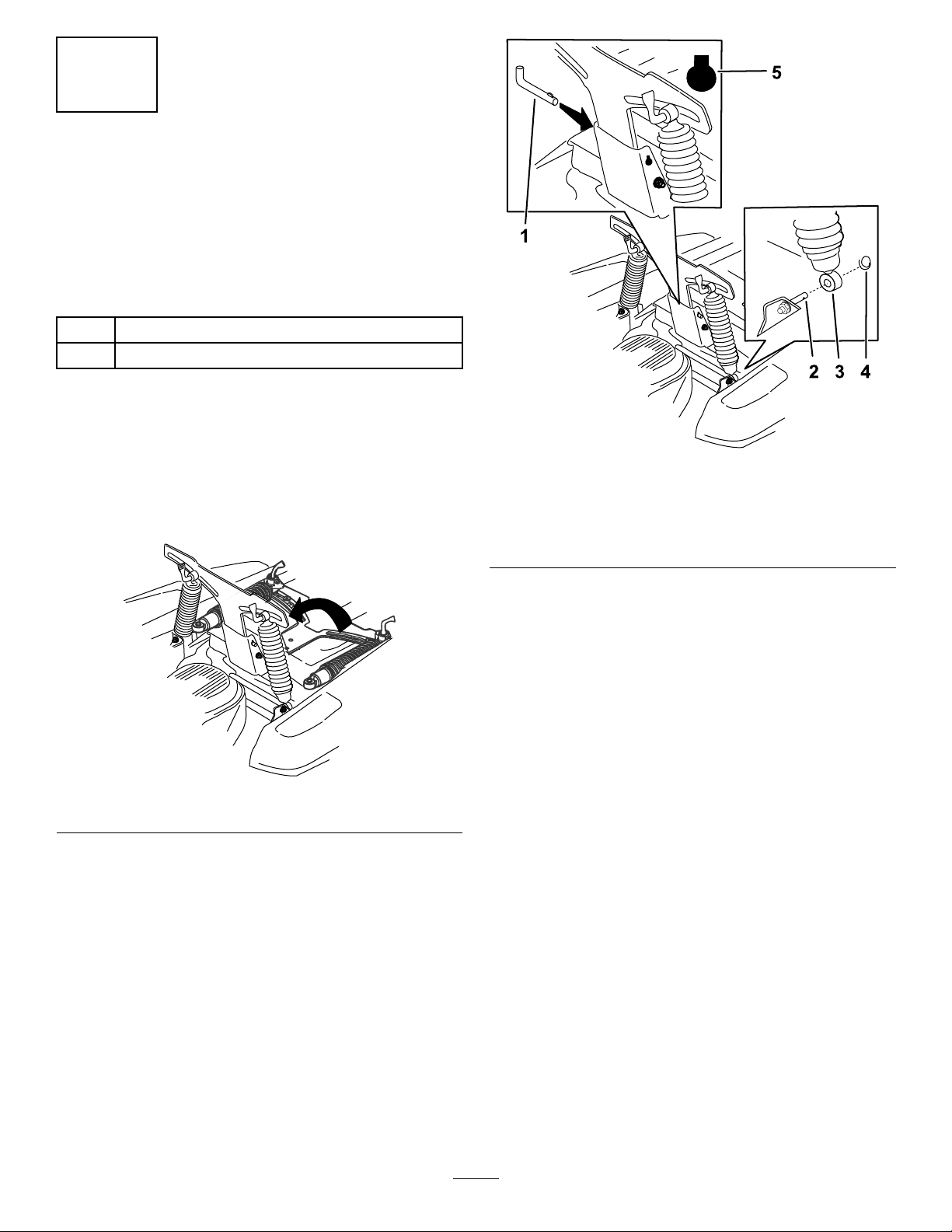
1
InstallingtheMyRide
Suspension
MachineswithMyRideSuspension
andShippedinaWoodCrateOnly
Partsneededforthisprocedure:
1Pin
2Roundclip
Procedure
1.Raisetheplatformandremovethewooden
blockfromabovethebattery.
Note:Youcandiscardthewoodenblock.
2.Rotatethesuspensionup(Figure1).
®
g233947
Figure2
1.Pin4.Roundclip
2.Post
3.Spring
5.Shapeofthekeyslot
Figure1
3.Placetheendsofthespringsontheposts
(Figure2).
4.Securethespringstothepostswiththe2round
clips(Figure2).
5.Installthepinintothebackbyusingtheindexed
keyslot(Figure2).
g233946
2
Page 3
2
3
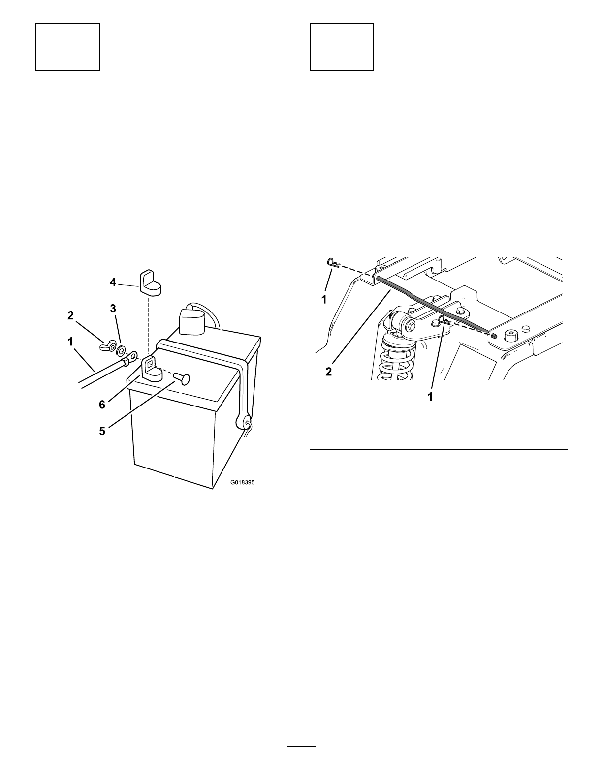
ConnectingtheBattery
NoPartsRequired
Procedure
1.Locatethebatteryandnegativebatterycable.
2.Removetheplasticcapfromthenegative
batterypost.
3.Removethefastenersonthenegativebattery
cable,andusethemtosecurethenegative
batterycabletothenegativebatterypost(Figure
3).
InstallingtheSeat
MachineswithMyRideSuspension
andShippedinaWoodCrateOnly
NoPartsRequired
Procedure
1.Removethe2hairpincottersfromtheseat-pivot
rod,andremovetheseat-pivotrodfromthe
platform(Figure4).
Figure3
1.Negativebatterycable4.Negativebatterypostcap
2.Wingnut
3.Washer6.Negativebatterypost
5.Carriagebolt
g233956
Figure4
1.Hairpincotter
g018395
2.Seat-pivotrod
3
Page 4

2.Placetheseatassemblyontotheplatform
(Figure5).
Figure5
4.Installahairpincotteron1sideoftheseat-pivot
rod,thenslidetheseat-pivotrodthroughthe
pivotbracketholeandseatpanhole(Figure7).
g233953
Figure7
5.Installtheotherhairpincotterontheotherside
oftheseat-pivotrod(Figure8).
g233955
3.Installtheseat-pivotrodbyinsertingtherod
fromthecenterandoutwardthroughthepivot
bracketholeandseatpanhole(Figure6).
Note:Ensurethattheseatpanisbetweenthe
2pivotbrackets.
Figure6
g233954
Figure8
g233952
4
Page 5
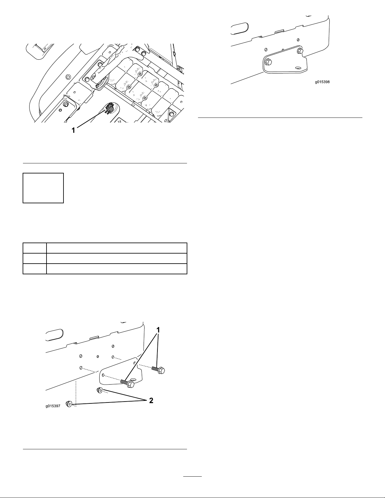
6.Rotatetheseatassemblyupwardandconnect
thewireharnesstotheseatswitchonthe
bottomoftheseat(Figure9).
Figure9
1.Seatswitch
4
g015398
Figure11
Afterassembly
g233951
InstallingtheRearHitch
Partsneededforthisprocedure:
1Rearhitch
2
Bolt(5/16x1inch)
2
Locknut(5/16inch)
Procedure
InstallthebrackettotheframeasshowninFigure10
andFigure11.
Figure10
Beforeassembly
1.Bolts2.Locknuts
g015397
5
Page 6

5
7
SettingUpthe
Motion-ControlLevers
NoPartsRequired
Procedure
1.Locatethemotion-controlleversattached,but
foldeddownonthemachine.
2.Removetheupperbolt(3/8x1inch)and
washer;loosenthelowerbolt(3/8x1inch).
3.Raisethemotioncontrolleverstotheupright
position.
4.Aligntheholesinthemotion-controlleverwith
theholesinthecontrol-armshaft,andinstallthe
boltandwasherremovedpreviously.Repeat
thisforbothcontrollevers.
Note:Handtightenallfasteners.
5.Movethemotion-controlleverstothepark
position,raisetheseat,andmovethecontrol
leversbacktothecenterposition(neutral).
CompletingtheSetup
Partsneededforthisprocedure:
1Ignitionkey
1
Hosecoupling(notincludedwithCEmodels)
1
Operator'sManual
1
Engineowner’smanual(non-T oroengines)
1
Operatortrainingmaterial
CheckingtheTirePressure
Checkthefrontandreartiresforproperination;
refertoCheckingtheTirePressureintheOperator’s
Manualfortherecommendedinationpressure.
CheckingtheSide-Discharge
Chute
Removethepackingrestraintholdingtheside
dischargechuteupandlowerthechuteintoplace.
6.Verifythatthemotion-controlleversareproperly
aligned.
Note:Adjustasnecessary.Tightenall
fasteners.
6
CheckingtheMower
Adjustment
NoPartsRequired
Procedure
Adjusttheside-to-sidelevelandthefront-to-rearblade
slope.UsetherelevantproceduresintheOperator's
Manualtoverifythatthedeckislevel,andmakeany
adjustmentsasnecessary .RefertotheOperator's
Manualformoreinformation.
CheckingtheEngine-OilLevel
Beforeyoustarttheengineandusethemachine,
checktheoillevelintheenginecrankcase;referto
CheckingtheOilLevelintheOperator'sManual.
OrganizingtheMaterial
Keepallthefollowingitemswiththemachine:
•Ignitionkey
•Hosecoupling(notincludedinCEmodels)
•Operator'sManual
•Engineowners’smanual(non-T oroengines)
•Viewtheoperatortrainingmaterialbefore
operatingthemachine.
6
Page 7

Notes:
Page 8

 Loading...