

Page 1

FormNo.3406-643RevA
TimeCutter
®
SS3225,SS4200,
andMX4200RidingMower
ModelNo.74710—SerialNo.316000001andUp
ModelNo.74720—SerialNo.316000001andUp
ModelNo.74765—SerialNo.316000001andUp
Registeratwww.T oro.com.
OriginalInstructions(EN)
*3406-643*A
Page 2
ItisaviolationofCaliforniaPublicResourceCode
G014523
1
Section4442or4443touseoroperatetheengineonany
forest-covered,brush-covered,orgrass-coveredlandunless
theengineisequippedwithasparkarrester,asdenedin
Section4442,maintainedineffectiveworkingorderorthe
engineisconstructed,equipped,andmaintainedforthe
preventionofre.
ThissparkignitionsystemcomplieswithCanadianICES-002
WARNING
CALIFORNIA
Proposition65Warning
Thisproductcontainsachemicalorchemicals
knowntotheStateofCaliforniatocausecancer,
birthdefects,orreproductiveharm.
Theengineexhaustfromthisproduct
containschemicalsknowntotheStateof
Californiatocausecancer,birthdefects,
orotherreproductiveharm.
GrossHorsepower
Introduction
Thismachineisaride-on,rotary-bladelawnmowerintended
tobeusedbyhomeownersinresidentialapplications.Itis
primarilydesignedforcuttinggrassonwell-maintainedlawns.
Itisnotdesignedforcuttingbrush,mowinggrassandother
growthalongsidehighways,orforagriculturaluses.
Readthisinformationcarefullytolearnhowtooperateand
maintainyourproductproperlyandtoavoidinjuryand
productdamage.Youareresponsibleforoperatingthe
productproperlyandsafely.
YoumaycontactTorodirectlyatwww .Toro.comforproduct
safetyandoperationtrainingmaterials,accessoryinformation,
helpndingadealer,ortoregisteryourproduct.
Wheneveryouneedservice,genuineT oroparts,oradditional
information,contactanAuthorizedServiceDealerorToro
CustomerServiceandhavethemodelandserialnumbersof
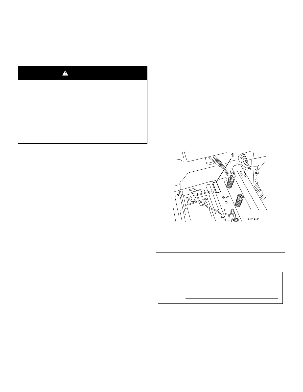
yourproductready.Figure1identiesthelocationofthe
modelandserialnumbersontheproduct.Writethenumbers
inthespaceprovided.
Thegrossornethorsepowerofthisenginewaslaboratory
ratedbytheenginemanufacturerinaccordancewiththe
SocietyofAutomotiveEngineers(SAE)J1940.Ascongured
tomeetsafety,emission,andoperatingrequirements,
theactualenginetorqueonthisclassofmowerwillbe
signicantlylower.
Gotowww .Toro.comtoviewspecicationsonyourmower
model.
Figure1
LocatedUndertheSeat
1.Modelandserial-numberplate
Writetheproductmodelandserialnumbersinthespace
below:
ModelNo.
SerialNo.
©2016—TheToro®Company
8111LyndaleAvenueSouth
Bloomington,MN55420
Thismanualidentiespotentialhazardsandhassafety
messagesidentiedbythesafetyalertsymbol(Figure2),
whichsignalsahazardthatmaycauseseriousinjuryordeath
ifyoudonotfollowtherecommendedprecautions.
Contactusatwww.Toro.com.
2
PrintedintheUSA
AllRightsReserved
Page 3

Figure2
1.Safety-alertsymbol
Thismanualuses2wordstohighlightinformation.
Importantcallsattentiontospecialmechanicalinformation
andNoteemphasizesgeneralinformationworthyofspecial
attention.
Important:Ifyouareusingthismachineabove1500m
(5,000ft)foracontinuousperiod,ensurethattheHigh
AltitudeKithasbeeninstalledsothattheenginemeets
CARB/EPAemissionregulations.TheHighAltitude
Kitincreasesengineperformancewhilepreventing
spark-plugfouling,hardstarting,andincreased
emissions.Onceyouhaveinstalledthekit,attach
thehigh-altitudelabelnexttotheserialdecalonthe
machine.ContactanyAuthorizedToroServiceDealer
toobtaintheproperHighAltitudeKitandhigh-altitude
labelforyourmachine.Tolocateadealerconvenientto
you,accessourwebsiteatwww.T oro.comorcontactour
ToroCustomerCareDepartmentatthenumber(s)listed
inyourEmissionControlWarrantyStatement.
Removethekitfromtheengineandrestoretheengine
toitsoriginalfactorycongurationwhenrunningthe
engineunder1500m(5,000ft).Donotoperateanengine
thathasbeenconvertedforhigh-altitudeuseatlower
altitudes;otherwise,youcouldoverheatanddamage
theengine.
Ifyouareunsurewhetherornotyourmachinehasbeen
convertedforhigh-altitudeuse,lookforthefollowing
label(Figure3).
Figure3
Contents
Safety...........................................................................4
SafeOperatingPractices...........................................4
ToroRidingMowerSafety........................................6
SlopeIndicator.......................................................7
SafetyandInstructionalDecals.................................8
ProductOverview.........................................................12
Controls...............................................................12
Operation....................................................................14
AddingFuel...........................................................14
CheckingtheEngine-OilLevel.................................15
BreakinginaNewMachine......................................15
ThinkSafetyFirst...................................................15
UnderstandingtheSafety-InterlockSystem................16
TestingtheSafety-InterlockSystem...........................16
StartingtheEngine.................................................17
OperatingtheBlades...............................................17
ShuttingOfftheEngine..........................................17
DrivingtheMachine...............................................18
StoppingtheMachine.............................................20
AdjustingtheHeightofCut.....................................20
PositioningtheSeat................................................20
AdjustingtheMotion-ControlLevers........................20
PushingtheMachinebyHand..................................21
AdjustingtheAnti-ScalpRollers...............................22
TransportingtheMachine........................................22
LoadingtheMachine..............................................22
OperatingTips......................................................24
Maintenance.................................................................25
RecommendedMaintenanceSchedule(s)......................25
PremaintenanceProcedures........................................26
RaisingtheSeat......................................................26
Lubrication...............................................................26
GreasingtheBearings.............................................26
EngineMaintenance..................................................27
ServicingtheAirCleaner.........................................27
ServicingtheEngineOil..........................................28
ServicingtheSparkPlug..........................................30
FuelSystemMaintenance...........................................31
ReplacingtheIn-LineFuelFilter...............................31
ElectricalSystemMaintenance....................................32
ChargingtheBattery...............................................32
ServicingtheFuses.................................................34
DriveSystemMaintenance.........................................34
CheckingtheTirePressure......................................34
ReleasingtheElectricBrake.....................................35
CoolingSystemMaintenance......................................35
CleaningtheEngineScreen......................................35
CleaningtheEngine-CoolingFinsand
Shrouds.............................................................35
MaintainingMower....................................................36
ServicingtheCuttingBlades.....................................36
LevelingtheMowerDeck........................................38
RemovingtheMower..............................................40
InstallingtheMower...............................................41
ReplacingtheGrassDeector..................................41
MaintainingtheMowerBelt(s).....................................42
ServicingtheMowerBelt(s).....................................42
Cleaning...................................................................44
WashingtheUndersideoftheMower........................44
Storage........................................................................45
CleaningandStoringtheMachine.............................45
Troubleshooting...........................................................46
Schematics...................................................................48
3
Page 4

Safety
ThismachinehasbeendesignedinaccordancewithANSI
standardB71.1-2012.
Toreducethepotentialforinjury,complywiththesesafety
instructionsandalwayspayattentiontothesafetyalert
symbol,whichmeansCaution,Warning,orDanger—personal
safetyinstruction.Failuretocomplywiththeinstructionmay
resultinpersonalinjuryordeath.
SafeOperatingPractices
Thisproductiscapableofamputatinghandsandfeetand
throwingobjects.Alwaysfollowallsafetyinstructionsto
avoidseriousinjuryordeath.
GeneralOperation
•Read,understand,andfollowallinstructionsinthe
Operator'sManualandonthemachinebeforestarting.
•Donotplaceyourhandsorfeetnearrotatingpartsor
underthemachine.Keepclearofthedischargeopening
atalltimes.
•Allowonlyresponsibleadultswhoarefamiliarwiththe
instructionstooperatethemachine.
•Cleartheareaofobjectssuchasrocks,toys,wire,etc.,
whichcouldbepickedupandthrownbytheblade.
•Besuretheareaisclearofotherpeoplebeforemowing.
Stopthemachineifanyoneentersthearea.
•Nevercarrypassengers.
•Donotmowinreverseunlessabsolutelynecessary.
Alwayslookdownandbehindbeforeandwhilebacking
up.
•Beawareofthemowerdischargedirectionanddonot
pointitatanyone.Avoiddischargingmaterialagainsta
wallorobstruction.Materialmayricochetbacktoward
you.Stoptheblade(s)whencrossinggravelsurfaces.
•Donotoperatethemachinewithoutdeector,discharge
coverorentiregrasscollectionsysteminplaceand
working.
•Bealert,slowdownandusecautionwhenmakingturns.
Lookbehindandtothesidebeforechangingdirections.
•Neverleavearunningmachineunattended.Alwaysturn
offtheblades,settheparkingbrake,shutofftheengine,
andremovethekeyfromtheignitionswitchbefore
dismountingthemachine.
•Turnoffthebladeswhennotmowing.Shutoffthe
engine,waitforallpartstocometoacompletestopand
removethekeyfromtheignitionswitchbeforecleaning
themachine,removingthegrasscatcherorunclogging
thedischargechute.
•Operatethemachineonlyindaylightorgoodarticial
light.
•Donotoperatethemachinewhileill,tired,orunderthe
inuenceofalcoholordrugs.
•Watchfortrafcwhenoperatingnearorcrossing
roadways.
•Useextracarewhenloadingorunloadingthemachine
intoatrailerortruck.
•Wearappropriateclothingincludingeyeprotection,
hearingprotection,andsubstantial,slip-resistantshoes.
Tiebacklonghair.Donotwearjewelry.
•Alwaysfollowtherecommendationsforanyapplication
ofcounterweights.
•Lightningcancausesevereinjuryordeath.Iflightning
isseenorthunderisheardinthearea,donotoperate
themachine;seekshelter.
SlopeOperation
Slopesareamajorfactorrelatedtolossofcontroland
tip-overaccidents,whichcanresultinsevereinjuryordeath.
Operationonallslopesrequiresextracaution.Ifyoucannot
backuptheslopeorifyoufeeluneasyonit,donotmowit.
•Donotmowslopesgreaterthan15degrees.
•Watchforditches,holes,rocks,dips,andrisesthatchange
theoperatingangle,asroughterraincouldoverturnthe
machine.
•Choosealowgroundspeedsothatyouwillnothaveto
stopwhileoperatingonaslope.
•Donotmowslopeswhengrassiswet.Slippery
conditionsreducetractionandcouldcauseslidingand
lossofcontrol.
•Alwayskeepthedrivewheelsengagedwhengoingdown
slopes.
•Reducespeedanduseextremecautiononslopes.
•Donotmakesuddenturnsorrapidspeedchanges.
•Removeormarkobstaclessuchasrocks,treelimbs,etc.
fromthemowingarea.Tallgrasscanhideobstacles.
•Avoidsuddenstartswhenmowinguphillbecausethe
mowermaytipbackwards.
•Beawarethatlossoftractionmayoccurgoingdownhill.
Weighttransfertothefrontwheelsmaycausedrive
wheelstoslipandcauselossofbrakingandsteering.
•Alwaysavoidsuddenstartingorstoppingonaslope.If
thetireslosetraction,stopthemachine,disengagethe
bladesandproceedslowlyoffdowntheslope.
•Useextremecarewithgrasscatchersorotherattachments.
Thesecanchangethestabilityofthemachineandcause
lossofcontrol.
•Donottrytostabilizethemachinebyputtingyourfoot
ontheground.
•Donotmowneardrop-offs,ditches,steepbanksor
water.Wheelsdroppingoveredgescancauserollovers,
whichmayresultinseriousinjury,deathordrowning.
•Useawalkbehindmowerand/orahandtrimmernear
drop-offs,ditches,steepbanksorwater.
4
Page 5

Children
SafeHandlingofGasoline
Tragicaccidentscanoccuriftheoperatorisnotalerttothe
presenceofchildren.Childrenareoftenattractedtothe
machineandthemowingactivity.Neverassumethatchildren
willremainwhereyoulastsawthem.
•Keepchildrenoutofthemowingareaandunderthe
watchfulcareofanotherresponsibleadult,notthe
operator.
•Bealertandturnthemachineoffifchildrenenterthe
area.
•Beforeandwhilebackingorchangingdirection,look
behind,down,andside-to-sideforsmallchildren.
•Nevercarrychildrenonthemachine,evenwiththe
bladesoff.Childrenmayfalloffandbeseriouslyinjured
orinterferewithsafeoperationofthemachine.
•Childrenwhohavebeengivenridesinthepastmay
suddenlyappearinthemowingareaforanotherrideand
berunoverorbackedoverbythemower.
•Neverallowchildrentooperatethemachine.
•Useextracarewhenapproachingblindcorners,shrubs,
trees,theendofafenceorotherobjectsthatmayobscure
vision.
TowingSafety
•Donotattachtowedequipmentexceptatthehitchpoint.
•Followtheattachmentmanufacturer'srecommendation
forweightlimitsfortowedequipmentandtowingon
slopes.Towedweightmustnotexceedtheweightof
themachine,operator,andballast.Usecounterweights
orwheelweightsasdescribedintheattachment,orin
towingthemachineOperator’sManual.
Toavoidpersonalinjuryorpropertydamage,useextracare
whenhandlinggasolineandotherfuels.Theyareammable
andthevaporsareexplosive.
•Extinguishallcigarettes,cigars,pipesandothersources
ofignition.
•Useonlyanapprovedcontainer.
•Neverremovethefuelcaporaddfuelwhentheengineis
running.Allowtheenginetocoolbeforerefueling.
•Neverrefuelthemachineindoors.
•Neverstorethemachineorfuelcontainerinsidewhere
thereisanopename,suchasnearawaterheateror
furnace.
•Neverllcontainersinsideavehicleoronatruckor
trailerwithaplasticliner.Alwaysplacecontainersonthe
groundawayfromyourvehiclebeforelling.
•Removefuel-poweredequipmentfromthetruckortrailer
andrefuelitontheground.Ifthisisnotpossible,then
refuelsuchequipmentwithaportablecontainer,rather
thanfromagasolinedispensernozzle.
•Keepthenozzleincontactwiththerimofthefueltank
orcontaineropeningatalltimesuntilthefuelingis
complete.Donotuseanozzlelock-opendevice.
•Ifyouspillfuelonclothing,changeyourclothing
immediately.
•Neveroverllthefueltank.Replacethefuelcapand
tightenitsecurely.
•Neverallowchildrenorothersinorontowedequipment.
•Onslopes,theweightofthetowedequipmentmaycause
lossoftraction,increasedriskofrollover,andlossof
control.Reducethetowedweightandslowdown.
•Thestoppingdistanceincreaseswiththeweightofthe
towedload.Travelslowlyandallowextradistancetostop.
•Makewideturnstokeeptheattachmentclearofthe
machine.
5
Page 6

GeneralService
•Neveroperateamachineinsideaclosedarea.Engine
exhaustcontainscarbonmonoxide,whichisanodorless,
deadlypoisonthatcankillyou.
•Keepnutsandboltstight,especiallythebladeattachment
bolts.Keepequipmentingoodcondition.
•Neverinterferewiththeintendedfunctionofasafety
deviceortoreducetheprotectionprovidedbyasafety
device.Checktheirproperoperationregularly.
•Keepthemachinefreeofgrass,leaves,orotherdebris
buildup.Cleanupoilorfuelspillsandfuel-soakeddebris.
Allowthemachinetocoolbeforestoring.
•Stopandinspecttheequipmentifyoustrikeanobject.
Repair,ifnecessary,beforerestarting.
•Nevermakeanyadjustmentsorrepairswiththeengine
running.
•Grasscatchercomponentsaresubjecttowear,damage
anddeterioration,whichcouldexposemovingpartsor
allowobjectstobethrown.Frequentlycheckcomponents
andreplacewithmanufacturers'recommendedparts,
whennecessary.
•Batterygasescanexplode.Keepcigarettes,sparks,and
amesawayfromthebattery.
•Ifloadingthemachineontoatrailerortruck,useasingle,
full-widthramponly.Therampangleshouldnotexceed
15degrees.
•Removingstandardoriginalequipmentpartsand
accessoriesmayalterthewarranty,traction,andsafety
ofthemachine.FailuretouseoriginalToropartscould
causeseriousinjuryordeath.Makingunauthorized
changestotheengine,fuelorventingsystem,mayviolate
EPAandCARBregulations.
•Replaceallpartsincluding,butnotlimitedto,tires,belts,
blades,andfuelsystemcomponentswithoriginalToro
parts.
•Mowerbladesaresharpandcancut.Wraptheblade(s)or
wearthickly-paddedgloves,anduseextracautionwhen
servicingthem.
•Checkforproperbrakeoperationfrequently .Adjustand
serviceasrequired.
•Maintainorreplacesafetyandinstructiondecalsas
necessary.
•UseonlygenuineTororeplacementpartstoensurethat
originalstandardsaremaintained.
ToroRidingMowerSafety
ThefollowinglistcontainssafetyinformationspecictoToro
productsorothersafetyinformationthatyoumustknowthat
maynotbeincludedintheANSIstandards.
•Shutofftheengine,movethemotion-controlleversto
NEUTRALandoutwardtothePARKposition,disengage
theblade-controlswitch,removethekeyfromthe
ignitionswitch,anddisconnectthespark-plugwire(s)
beforeperforminganyservice,repairs,maintenance,or
adjustments.
•Keephands,feet,hair,andlooseclothingawayfrom
attachmentdischargearea,undersideofmowerandany
movingpartswhileengineisrunning.
•Donottouchequipmentorattachmentpartswhichmay
behotfromoperation.Allowtocoolbeforeattempting
tomaintain,adjustorservice.
•Batteryacidispoisonousandcancauseburns.Avoid
contactwithskin,eyes,andclothing.Protectyourface,
eyes,andclothingwhenworkingwithabattery.
6
Page 7
SlopeIndicator
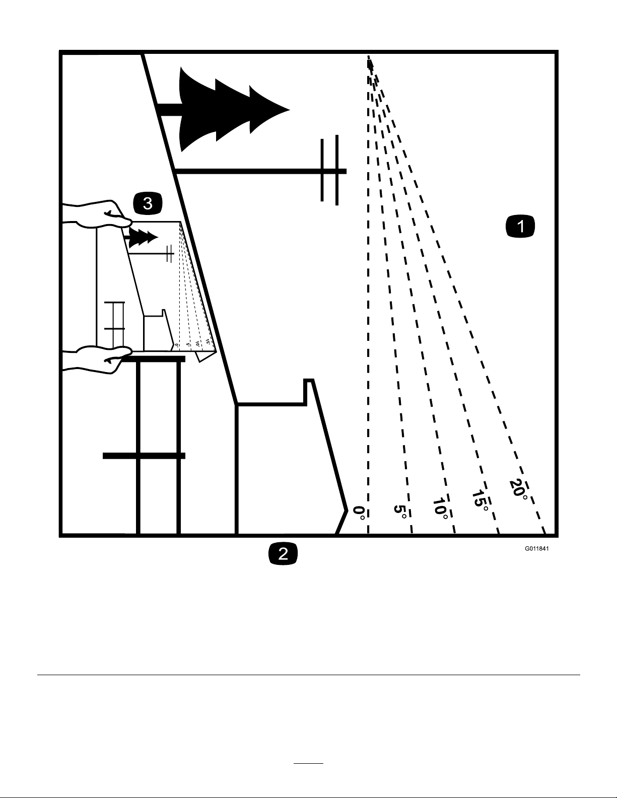
G011841
Figure4
Thispagemaybecopiedforpersonaluse.
1.Themaximumslopeyoucansafelyoperatethemachineonis15degrees.Usetheslopecharttodeterminethedegreeofslope
ofhillsbeforeoperating.Donotoperatethismachineonaslopegreaterthan15degrees.Foldalongtheappropriateline
tomatchtherecommendedslope.
2.Alignthisedgewithaverticalsurface,atree,building,fencepole,etc.
3.Exampleofhowtocompareslopewithfoldededge.
7
Page 8
SafetyandInstructionalDecals
Safetydecalsandinstructionsareeasilyvisibletotheoperatorandarelocatednearanyareaofpotential
danger.Replaceanydecalthatisdamagedorlost.
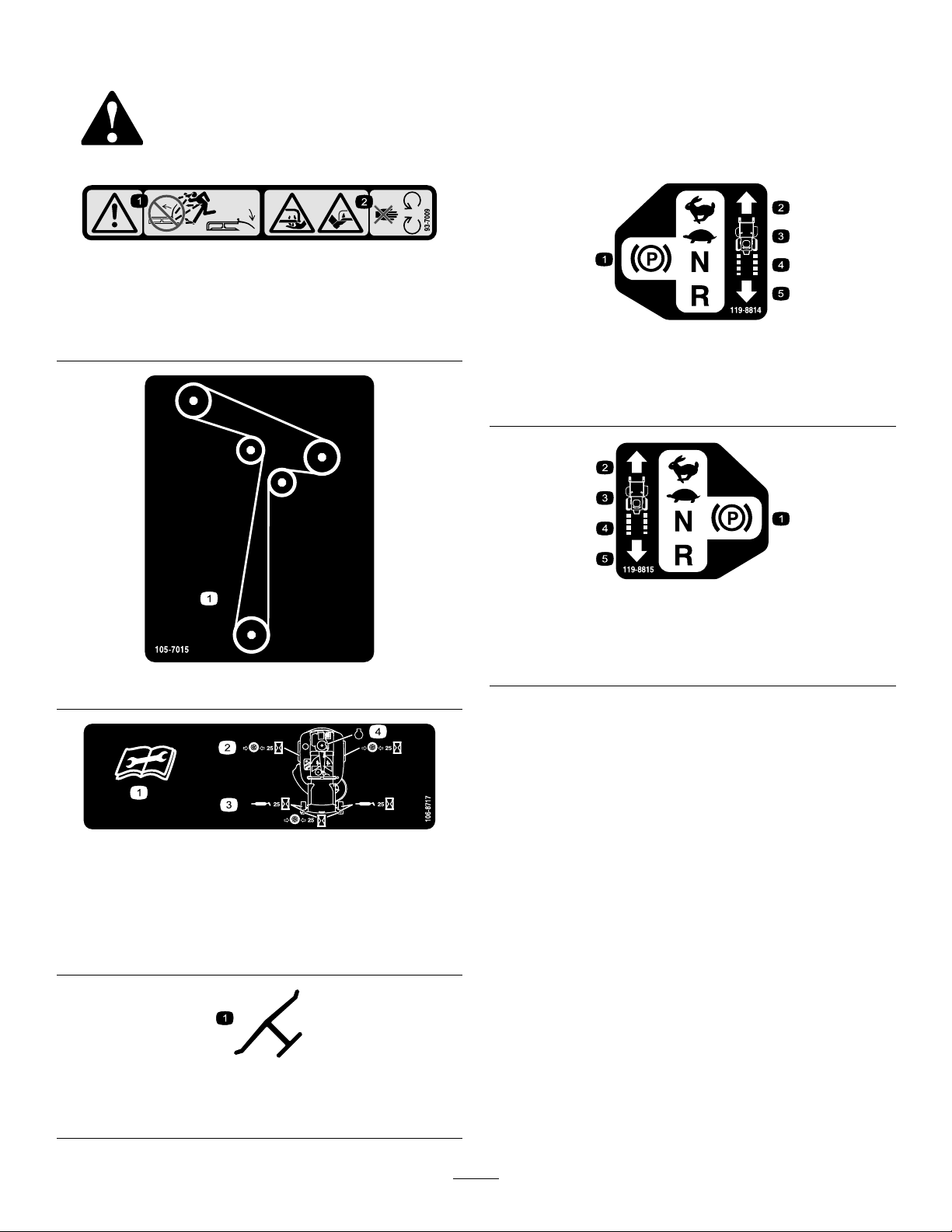
93-7009
1.Warning—don'toperatethemowerwiththedeectorupor
removed;keepthedeectorinplace.
2.Cutting/dismembermenthazardofhandorfoot,mower
blade—stayawayfrommovingparts.
119-8814
1.Parkingposition4.Neutral
2.Fast5.Reverse
3.Slow
105-7015
106-8717
1.Readtheinstructionsbeforeservicingorperforming
maintenance.
2.Checktirepressureevery25operatinghours.
3.Greaseevery25operatinghours.
4.Engine
119-8815
1.Parkingposition4.Neutral
2.Fast5.Reverse
3.Slow
Manufacturer'sMark
1.Indicatesthebladeisidentiedasapartfromtheoriginal
machinemanufacturer.
8
Page 9
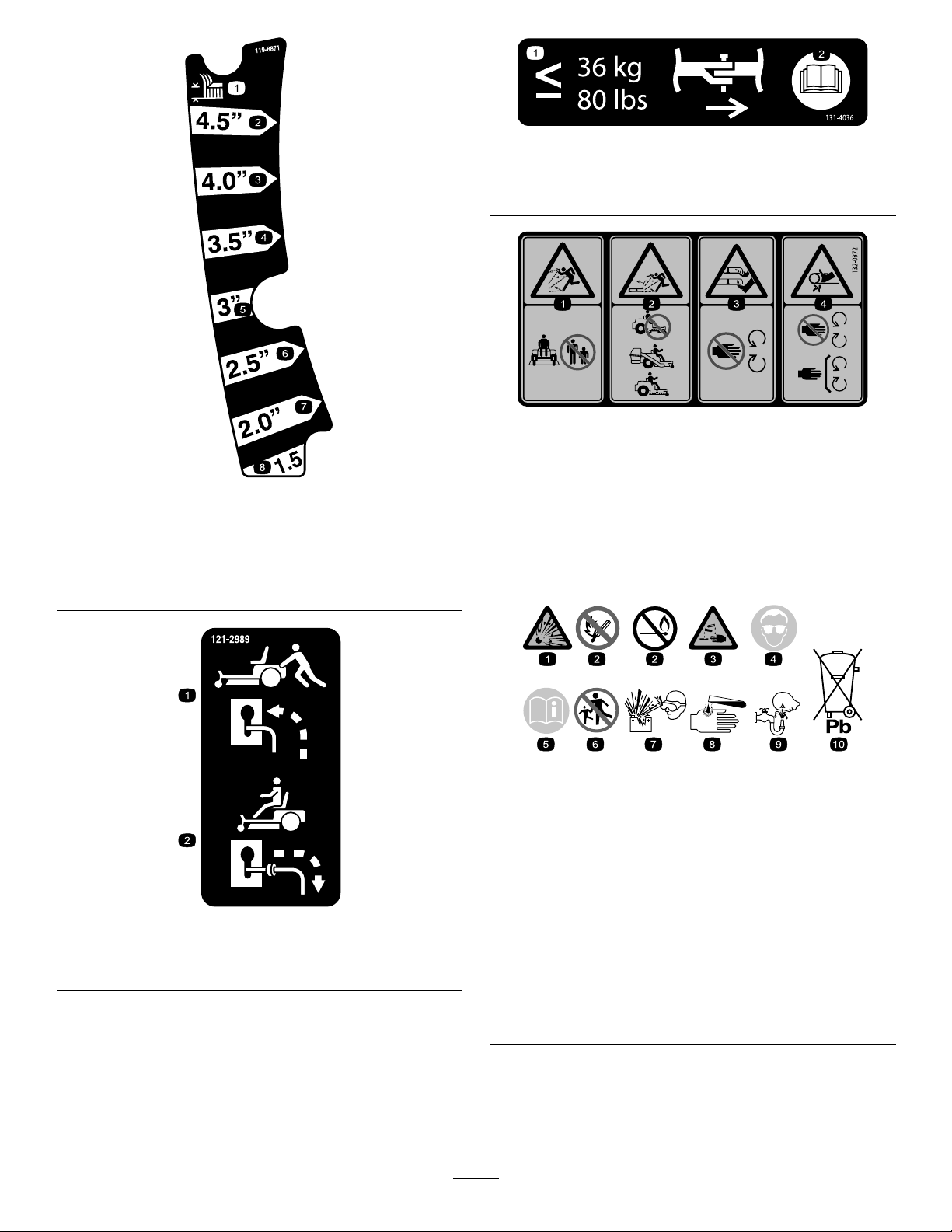
131-4036
1.Maximumdrawbarpull36kg(80lb)
2.ReadtheOperator'sManual.
132-0872
119-8871
1.Heightofcut5.76mm(3inches)
2.115mm(4.5inches)6.63mm(2.5inches)
3.101mm(4inches)7.50mm(2inches)
4.88mm(3.5inches)8.38mm(1.5inches)
121-2989
1.Bypassleverpositionfor
pushingthemachine
2.Bypassleverpositionfor
operatingthemachine
1.Thrownobject
hazard—keepbystanders
awayfromthemachine.
2.Thrownobjecthazard,
raisedbafe—donot
operatethemachinewith
anopendeck;usea
baggerorabafe.
3.Severinghazardofhand
4.Entanglement
BatterySymbols
Someorallofthesesymbolsareonyourbattery
1.Explosionhazard
2.Nore,opename,or
smoking
3.Causticliquid/chemical
burnhazard
4.Weareyeprotection.9.Flusheyesimmediately
5.ReadtheOperator's
Manual.
6.Keepbystandersasafe
7.Weareyeprotection;
8.Batteryacidcancause
10.Containslead;donot
orfoot—keepawayfrom
movingparts.
hazard—keepaway
frommovingparts;keep
allguardsandshieldsin
place.
distancefromthebattery.
explosivegasescan
causeblindnessandother
injuries.
blindnessorsevereburns.
withwaterandgetmedical
helpfast
discard
9
Page 10

121-0771
1.Choke4.Slow
2.Fast
3.Continuousvariablesetting
131–3947
5.Powertake-off(PTO),blade-controlswitch
1.Trim—slow
2.Tow—medium
3.Mow—fast
10
Page 11
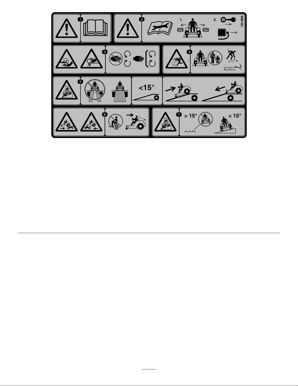
132-0869
1.Warning—readthe
Operator'sManual.
2.Warning—beforeservicing,
engagetheparkingbrake,
removethekeyfromthe
ignitionswitchandthe
sparkplugconnection.
3.Cuttinghazardofhand,
mowerblade;pinching
hazardofhand,belt—keep
handsandfeetawayfrom
movingparts;keepall
guardsandshieldsinplace.
4.Thrownobject
hazard—keepbystanders
awayfromthemachine;
removedebrisfromthe
areabeforemowing;keep
thedeectorshielddown.
5.Ramptipping
hazard—whenloading
ontoatrailer,donotuse
dualramps;onlyusea
singlerampwideenough
forthemachineandthat
hasaninclinelessthan
15degrees;backupthe
ramp(inreverse)anddrive
forwardofftheramp.
6.Bodilyharmhazard—no
riders;lookbehindyou
whenmowinginreverse.
7.Tippinghazardon
slopes—donotuseon
slopesnearopenwater;do
notuseonslopesgreater
than15degrees.
11
Page 12
ProductOverview
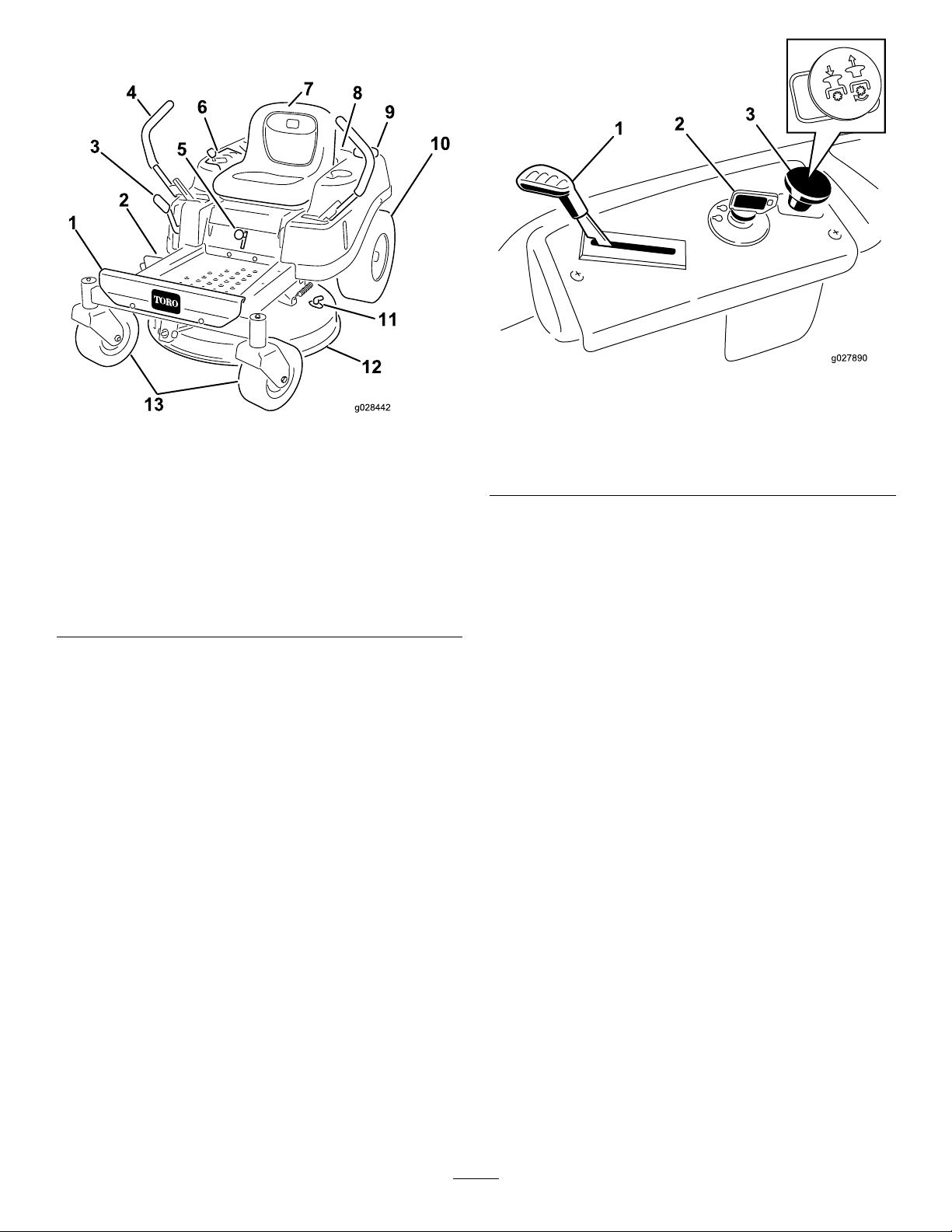
Figure6
ControlPanel
Figure5
Modelwith81cm(32-inch)DeckShown
1.Footrest8.Engine
2.Deector
3.Height-of-cutlever
4.Motion-controllever
5.Smart-speedlever
6.Controlpanel
7.Operatorseat
9.Fuel-tankcap
10.Reardrivewheel
11.Washouttting
12.Mowerdeck
13.Frontcasterwheels
Controls
BecomefamiliarwithallofthecontrolsinFigure5and
Figure6beforeyoustarttheengineandoperatethemachine.
1.Throttle/Choke
2.Ignitionswitch
3.Blade-controlswitch
(powertakeoff)
IgnitionSwitch
Theignitionswitchhas3positions:OFF,RUN,andSTART.
ThekeyturnstoSTARTandmovesbacktoRUNupon
release.TurningthekeytotheOFFpositionshutsoffthe
engine;however,alwaysremovethekeyfromtheignition
switchwhenleavingthemachinetopreventsomeonefrom
accidentallystartingtheengine(Figure6).
Throttle/ChokeControl
Thethrottleandchokearecombinedinto1control
lever.Thethrottlecontrolstheenginespeedandhasa
continuous-variablesettingfromtheSLOWpositiontothe
FASTposition.Engagethechokebymovingtheleverpast
theFASTsettinguntilitstops(Figure6).
Itmaybenecessarytoholdtheleveragainstthestop,inthe
chokeposition,whiletryingtostarttheengine.
Note:Awarmorhotenginemaynotrequirechoking.
Blade-ControlSwitch(PowerTakeoff)
Theblade-controlswitch,representedbyapowertakeoff
(PTO)symbol,engagesanddisengagespowertothemower
blades(Figure6).
Motion-ControlLeversandPark
Position
Themotion-controlleversarespeed-sensitivecontrolsof
independent-wheelmotors.Movingaleverforwardor
backwardturnsthewheelonthesamesideforwardorin
reverse;wheelspeedisproportionaltotheamountthelever
12
Page 13
ismoved.Movethecontrolleversoutwardfromthecenter
G014521
1
tothePARKpositionwhenexitingthemachine(Figure14).
Alwayspositionthemotion-controlleversintothePARK
positionwhenyoustopthemachineorleaveitunattended.
SmartSpeed™ControlSystemLever
TheSmartSpeed™Control-Systemlever,locatedbelowthe
operatingposition,givestheoperatorachoicetodrivethe
machineat3speedranges—trim,tow ,andmow(Figure17).
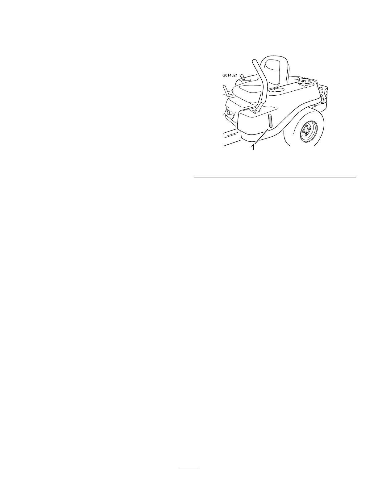
Fuel-PresenceWindow
hefuelwindowlocatedontheleft-handsideofthemachine,
canbeusedtoverifythepresenceofgasolineinthetank
(Figure7).
Figure7
1.Fuel-presencewindow
Height-of-CutLever
Theheight-of-cutleverallowsyoutoraiseandlowerthe
deckfromtheseatedposition.Movingtheleverup(toward
you)raisesthedeck;movingtheleverdown(awayfromyou)
lowersthedeck.Donotadjusttheheight-of-cutwhilethe
machineismoving(Figure5).
13
Page 14

Operation
Note:Determinetheleftandrightsidesofthemachine
fromthenormaloperatingposition.
AddingFuel
•Forbestresults,useonlyclean,fresh(lessthan30days
old),unleadedgasolinewithanoctaneratingof87or
higher((R+M)/2ratingmethod).
•Ethanol:Gasolinewithupto10%ethanol(gasohol)
or15%MTBE(methyltertiarybutylether)byvolume
isacceptable.EthanolandMTBEarenotthesame.
Gasolinewith15%ethanol(E15)byvolumeisnot
approvedforuse.Neverusegasolinethatcontains
morethan10%ethanolbyvolume,suchasE15
(contains15%ethanol),E20(contains20%ethanol),or
E85(containsupto85%ethanol).Usingunapproved
gasolinemaycauseperformanceproblemsand/orengine
damagewhichmaynotbecoveredunderwarranty.
•Donotusegasolinecontainingmethanol.
•Donotstorefueleitherinthefueltankorfuelcontainers
overthewinterunlessyouuseafuelstabilizer.
•Donotaddoiltogasoline.
DANGER
Incertainconditionsduringfueling,static
electricitycanbereleasedcausingasparkwhich
canignitethegasolinevapors.Areorexplosion
fromgasolinecanburnyouandothersandcan
damageproperty.
•Alwaysplacegasolinecontainersontheground
awayfromyourvehiclebeforelling.
•Donotllgasolinecontainersinsideavehicleor
onatruckortrailerbedbecauseinteriorcarpets
orplastictruckbedlinersmayinsulatethe
containerandslowthelossofanystaticcharge.
•Whenpractical,removegas-poweredequipment
fromthetruckortrailerandrefueltheequipment
withitswheelsontheground.
•Ifthisisnotpossible,thenrefuelsuch
equipmentonatruckortrailerfromaportable
containerratherthanfromagasolinedispenser
nozzle.
•Ifyoumustuseafueldispensernozzle,keepthe
nozzleincontactwiththerimofthefueltank
orcontaineropeningatalltimesuntilfuelingis
complete.
DANGER
Incertainconditions,gasolineisextremely
ammableandhighlyexplosive.Areorexplosion
fromgasolinecanburnyouandothersandcan
damageproperty.
•Fillthefueltankoutdoors,inanopenarea,
whentheengineiscold.Wipeupanygasoline
thatspills.
•Neverllthefueltankinsideanenclosedtrailer.
•Donotllthefueltankcompletelyfull.Add
gasolinetothefueltankuntilthelevelis6to13
mm(1/4to1/2inch)belowthebottomofthe
llerneck.Thisemptyspaceinthetankallows
gasolinetoexpand.
•Neversmokewhenhandlinggasoline,andstay
awayfromanopenameorwheregasoline
fumesmaybeignitedbyaspark.
•Storegasolineinanapprovedcontainerand
keepitoutofthereachofchildren.Neverbuy
morethana30-daysupplyofgasoline.
•Donotoperatewithoutentireexhaustsystemin
placeandinproperworkingcondition.
WARNING
Gasolineisharmfulorfatalifswallowed.Long-term
exposuretovaporscancauseseriousinjuryand
illness.
•Avoidprolongedbreathingofvapors.
•Keepfaceawayfromnozzleandgastankor
conditionerbottleopening.
•Avoidcontactwithskin;washoffspillswith
soapandwater.
UsingStabilizer/Conditioner
Useafuelstabilizer/conditionerinthemachinetoprovide
thefollowingbenets:
•Keepsgasolinefreshduringstorageof90daysorless.
Forlongerstorageitisrecommendedthatthefueltank
bedrained.
•Cleanstheenginewhileitruns
•Eliminatesgum-likevarnishbuildupinthefuelsystem,
whichcauseshardstarting
Important:Donotusefueladditivescontaining
methanolorethanol.
Addthecorrectamountoffuelstabilizer/conditioner
tothegasoline.
Note:Afuelstabilizer/conditionerismosteffective
whenmixedwithfreshgasoline.T ominimizethechance
14
Page 15
ofvarnishdepositsinthefuelsystem,usefuelstabilizer
g027243
A
B
E
D
C
atalltimes.
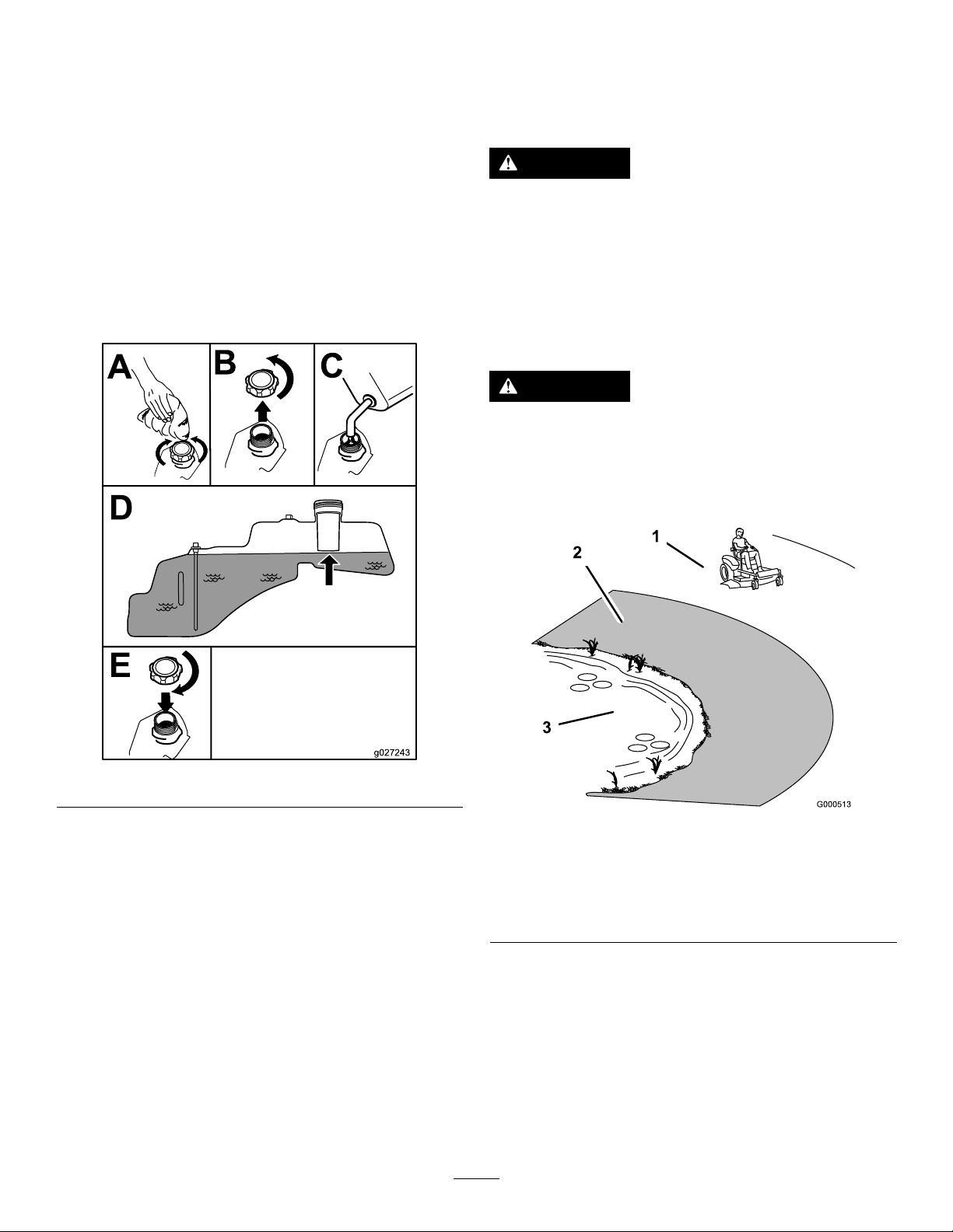
FillingtheFuelTank
Note:Ensurethattheengineisshutoffandthemotion
controlsareintheparkedposition.
ThinkSafetyFirst
Pleasereadallsafetyinstructionsandsymbolsinthesafety
section.Knowingthisinformationcouldhelpyouor
bystandersavoidinjury.
DANGER
Note:Youcanusethefuelwindowtoverifythepresenceof
gasolinebeforellingthetank(Figure8).
Important:Donotoverllfueltank.Fillthefueltank
tothebottomofthellerneck.Theemptyspaceinthe
tankallowsthefueltoexpand.Overllingmayresultin
fuelleakage,damagetotheengine,ordamagetothe
emissionssystem.
Operatingthemachineonwetgrassorsteepslopes
cancauseslidingandlossofcontrol.
•Donotoperateonslopesgreaterthan15degrees.
•Reducespeedanduseextremecautionon
slopes.
•Donotoperatethemachinenearwater.
DANGER
Wheelsdroppingoveredgescancauserollovers,
whichmayresultinseriousinjury,death,or
drowning.
Donotoperatethemachineneardrop-offs.
Figure8
CheckingtheEngine-OilLevel
Beforeyoustarttheengineandusethemachine,check
theoillevelintheenginecrankcase;refertoCheckingthe
Engine-OilLevel(page28).
BreakinginaNewMachine
Newenginestaketimetodevelopfullpower.Mowerdecks
anddrivesystemshavehigherfrictionwhennew,placing
additionalloadontheengine.Allow40to50hoursof
break-intimefornewmachinestodevelopfullpowerand
bestperformance.
1.Safezone—usethe
machinehere.
2.Useawalk-behindmower
and/orhandtrimmernear
drop-offsandwater.
15
Figure9
3.Water
Page 16
CAUTION
G009027
1
2
TestingtheSafety-Interlock
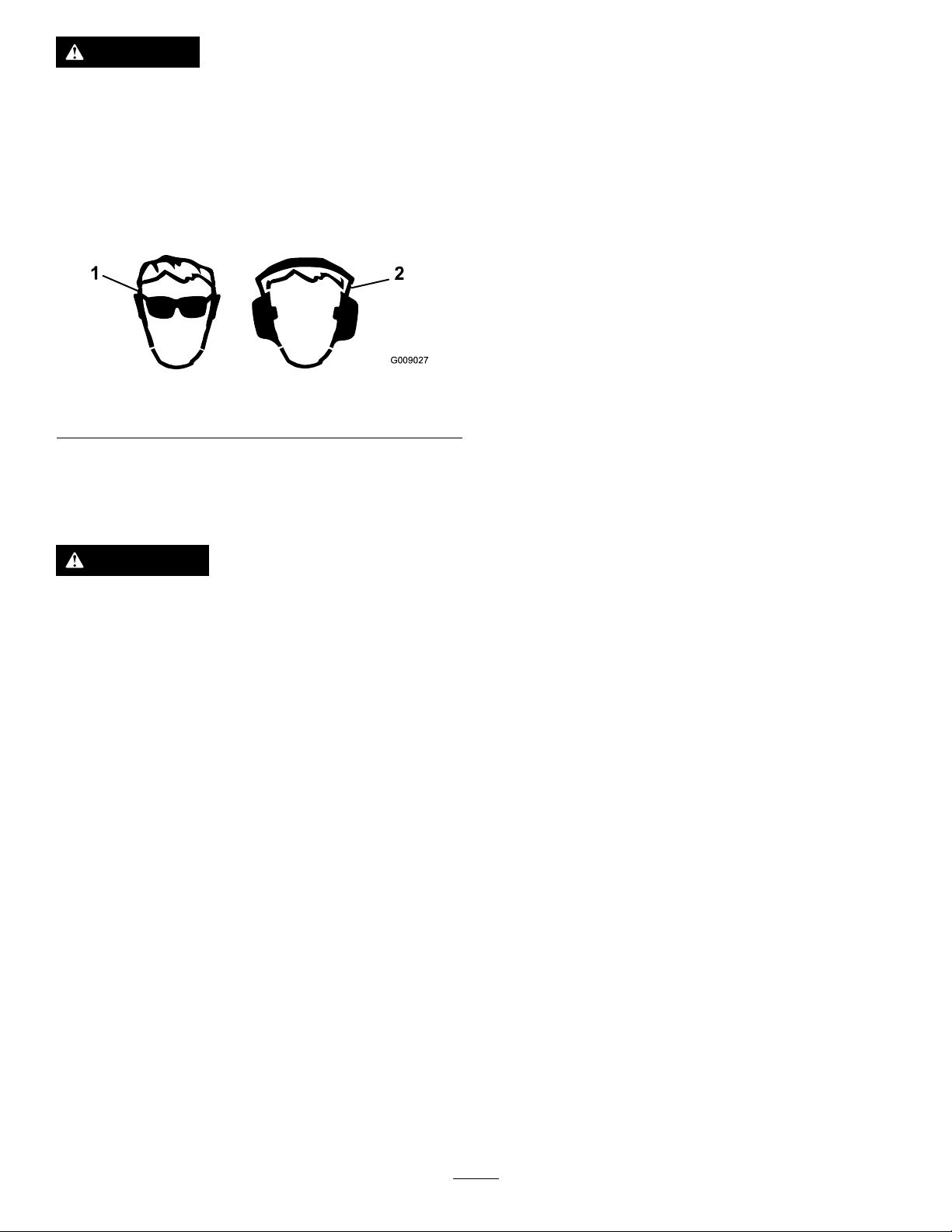
Thismachineproducessoundlevelsinexcessof
85dBAattheoperator’searandcancausehearing
lossthroughextendedperiodsofexposure.
Wearhearingprotectionwhenoperatingthis
machine.
Useingprotectiveequipmentforeyes,ears,hands,feet,and
headisrecommended.
Figure10
1.Weareyeprotection.2.Wearhearingprotection.
Understandingthe Safety-InterlockSystem
WARNING
Ifthesafety-interlockswitchesaredisconnectedor
damaged,themachinecouldoperateunexpectedly,
causingpersonalinjury.
System
Testthesafety-interlocksystembeforeyouusethemachine
eachtime.Ifthesafetysystemdoesnotoperateasdescribed
below,haveanAuthorizedServiceDealerrepairthesafety
systemimmediately.
1.Whilesittingontheseat,withthecontrolleversinthe
PARKposition,andmovetheblade-controlswitchto
theONposition.Trystartingtheengine;theengine
shouldnotstart.
2.Whilesittingontheseat,movetheblade-controlswitch
totheOFFposition.Moveeithermotioncontrol
levertothecenter,unlockedposition.Trystartingthe
engine;theengineshouldnotstart.Repeatwiththe
othermotion-controllever.
3.Whilesittingontheseat,movethebladecontrolswitch
totheOFFposition,andlockthemotion-controllevers
inthePARKposition.Starttheengine.Whilethe
engineisrunning,engagetheblade-controlswitch,and
riseslightlyfromtheseat;theengineshouldshutoff.
4.Whilesittingontheseat,movetheblade-controlswitch
totheOFFposition,andlockthemotion-controllevers
inthePARKposition.Starttheengine.Whilethe
engineisrunning,movethemotion-controlleversto
thecenter,unlockedposition,engagetheblade-control
switch,andriseslightlyfromtheseat;theengine
shouldshutoff.
•Donottamperwiththeinterlockswitches.
•Checktheoperationoftheinterlockswitches
dailyandreplaceanydamagedswitchesbefore
operatingthemachine.
Thesafety-interlocksystemisdesignedtopreventtheengine
fromstartingunless:
•Thebladesaredisengaged.
•Themotion-controlleversareinthePARKposition.
Thesafety-interlocksystemalsoisdesignedtoshutoffthe
enginewheneverthecontrolleversareoutofthePARK
positionandyourisefromtheseat.
16
Page 17

StartingtheEngine
g027535
B
C
D
E
A
G
F
g027247
OperatingtheBlades
Important:Donotengagethestarterformorethan
5secondsatatime.Engagingthestartermotorfor
morethan5secondscandamagethestartermotor.If
theenginefailstostart,wait10secondsbeforeoperating
theenginestarteragain.
Note:Itmaybenecessarytoholdtheleveragainstthe
stop,intheCHOKEposition,whiletryingtostarttheengine
(Figure11).
Theblade-controlswitchengagesanddisengagespower
tothemowerblades.Thisswitchcontrolspowertoany
attachmentsthatdrawpowerfromtheengine,includingthe
mowerdeckandcuttingblades.
EngagingtheBlades
Important:Donotengagethebladeswhenparkedin
tallgrass;beltorclutchdamagecanoccur.
Note:Alwaysengagethebladeswiththethrottleinthe
FASTposition.
Figure12
DisengagingtheBlades
Figure11
Figure13
1.Controlpanel2.Blade-controlswitch—Off
ShuttingOfftheEngine
1.Disengagethebladesbymovingtheblade-control
switchtotheOFFposition(Figure13).
2.MovethethrottlelevertotheFASTposition.
3.TurnthekeytotheOFFpositionandremovethekey
fromtheignitionswitch.
17
Page 18

DrivingtheMachine
G008952
DrivingForward
Drivingthemachinebenetsfromanunderstandingof
whatzero-turn-radiusmowermeans.Thedrivewheelsturn
independently,poweredbyhydraulicmotorsoneachaxle;
hence1sidecanturninreversewhiletheotherturnsforward,
causingthemachinetospinratherthanturn.Thisvastly
improvesthemachinemaneuverabilitybutmayrequiresome
adjustmentifyouareunfamiliar.
WARNING
Themachinecanspinveryrapidly.Y oumaylose
controlofthemachineandcausepersonalinjuryor
damagetothemachine.
•Usecautionwhenmakingturns.
•Slowthemachinedownbeforemakingsharp
turns.
Thethrottlecontrolregulatestheenginespeedasmeasured
inrpm(revolutionsperminute).Placingthethrottlecontrol
intheFASTpositioncanbebestforperformance.Formost
applications,operatethemachineinthefull-throttleposition.
Note:Alwaysusecautionwhenbackingupandturning.
1.Movetheleverstothecenter,unlockedposition.
2.Togoforward,slowlypushthemotion-controllevers
forward(Figure15).
Figure15
Figure14
1.PARKposition4.Backward
2.Center,unlockposition5.Frontofthemachine
3.Forward
Togostraight,applyequalpressuretoboth
motion-controllevers(Figure15).
Toturn,releasepressureonthemotion-controllever
towardthedirectionyouwanttoturn(Figure15).
Thefartheryoumovethemotion-controlleversin
eitherdirection,thefasterthemachinemovesinthat
direction.
Tostopthemachine,pullthemotion-controllevers
totheNEUTRALposition.
18
Page 19

DrivingBackward
G008953
Tochangespeeds,dothefollowing:
Note:Alwaysusecautionwhenbackingupandturning.
1.Movetheleverstothecenter,unlockedposition.
2.Togobackward,lookbehindyouanddown,asyou
slowlypullthemotion-controlleversrearward(Figure
16).
Figure16
1.Movethemotion-controlleverstotheNEUTRAL
positionandoutwardtothePARKposition.
2.Disengagetheblade-controlswitch.
3.Adjustthelevertothedesiredposition.
Thefollowingareonlyrecommendationsforuse.
Adjustmentsvarybygrasstype,moisturecontent,andthe
heightofthegrass.
Suggested
uses:
ParkingX
Heavy,wet
grass
TrainingX
BaggingX
MulchingX
Normal
mowing
TransportX
TrimTowMow
X
X
Trim
Togostraight,applyequalpressuretoboth
motion-controllevers(Figure16).
Toturn,releasethepressureonthemotion-control
levertowardthedirectionyouwanttoturn.
Tostopthemachine,pushthemotion-controllevers
totheNEUTRALposition.
UsingtheSmartSpeed
TM
Control
System
TheSmartSpeed
operatingposition(Figure17),givestheoperatorachoice
todrivethemachineat3groundspeedranges—trim,tow ,
andmow .
TM
Control-Systemlever,locatedbelowthe
Thisisthelowestspeed.Thesuggestedusesforthisspeed
areasfollows:
•Parking
•Heavy,wetgrassmowingconditions
•Training
Tow
Thisisthemediumspeed.Thesuggestedusesforthisspeed
areasfollows:
•Bagging
•Mulching
Mow
Thisisthefastestspeed.Thesuggestedusesforthisspeed
areasfollows:
•Normalmowing
•Transportingthemachine
1.Smart-speedlever
Figure17
19
Page 20

StoppingtheMachine
g027249
B
C
A
g027252
B
A
PositioningtheSeat
Tostopthemachine,movethemotion-controlleversto
theNEUTRALpositionandoutwardtothePARKposition,
disengagetheblade-controlswitch,ensurethethrottleis
betweenhalfandfullthrottle,andturntheignitionkeytothe
OFFposition.Removethekeyfromtheignitionswitch.
WARNING
Childrenorbystandersmaybeinjuredifthey
moveorattempttooperatethemowerwhileitis
unattended.
Alwaysremovetheignitionkeyandmovethe
motion-controlleversoutwardtothePARKposition
whenleavingthemachineunattended,evenifjust
forafewminutes.
AdjustingtheHeightofCut
Note:Thetransportpositionisthehighestheight-of-cut
positionorcuttingheight115mm(4.5inches)asshownin
Figure18.
Heightofcutiscontrolledbytheleverlocatedtotherightof
theoperatingposition(Figure18).
MovetheseatforwardorbackwardasshowninFigure19.
Figure19
AdjustingtheMotion-Control Levers
AdjustingtheHeight
Youcanadjustthemotion-controllevershigherorlowerfor
maximumcomfort(Figure20).
Figure20
Figure18
20
Page 21

AdjustingtheTilt
g017303
1 2
3
Youcanadjustthemotion-controlleversforwardorrearward
foryourcomfort.
1.Loosentheupperboltholdingthecontrollevertothe
control-armshaft.
2.Loosenthelowerboltjustenoughtopivotthecontrol
leverforwardorrearward(Figure20).
3.Tightenbothboltstosecurethecontrolleverinthe
newposition.
4.Repeattheadjustmentfortheothercontrollever.
PushingtheMachinebyHand
Important:Alwayspushthemachinebyhand.Donot
towthemachine,becausedamagemayoccur.
Thismachinehasanelectric-brakemechanism,andtopush
themachine,theignitionkeyneedstobeintheRUNposition.
Thebatteryneedstobechargedandfunctioningforthe
electricbraketobedisengage.
PushingtheMachine
1.Parkthemachineonalevelsurface,anddisengagethe
blade-controlswitch.
2.Movethemotion-controlleversoutwardtothePARK
position,shutofftheengine,andwaitforallmoving
partstostopbeforeleavingtheoperatingposition.
3.Locatethebypassleversontheframeonbothsidesof
theengine.
4.Movethebypassleversforwardthroughthekeyhole
anddowntolocktheminplace(Figure21).
Note:Dothisforeachlever.
Figure21
1.Bypass-leverlocations
2.Leverpositionfor
operatingthemachine
6.Whennished,ensurethatthekeyhasbeenreturnedto
theSTOPpositiontoavoiddrainingthebatterycharge.
Note:Ifthemachinefailstomove,theelectricbrakemay
stillbeengaged.Ifnecessary,youcanreleasetheelectricbrake
manually;refertoReleasingtheElectricBrake(page35).
3.Leverpositionforpushing
themachine
OperatingtheMachine
Movethebypassleversrearwardthroughthekeyholeand
downtolocktheminplaceasshowninFigure21.
Note:Dothisforeachlever.
5.Movethemotion-controlleversinwardtotheNEUTRAL
positionandturntheignitionkeytotheRUNposition.
Note:Donotstartthemachine.
Note:Youcannowpushthemachinebyhand.
21
Page 22

AdjustingtheAnti-Scalp
g019929
1
2
3
4
5
WARNING
Rollers
For107cm(42-inch)MowerDecks
Wheneveryouchangetheheightofcut,adjusttheheight
oftheanti-scalprollers.
Note:Adjusttheanti-scalprollerssotherollersdonottouch
thegroundinnormal,atmowingareas.
1.Disengagetheblade-controlswitch(PTO),movethe
motion-controlleverstotheNEUTRAL-LOCKposition,
andsettheparkingbrake.
2.Shutofftheengine,removethekeyfromtheignition
switch,andwaitforallmovingpartstostopbefore
leavingtheoperatingposition.
3.Adjusttheanti-scalprollersto1ofthefollowing
positions:
•Upperhole—usethispositionwiththemower
deckinthe63mm(2-1/2inches)andbelowthe
height-of-cutpositions(Figure22).
•Lowerhole—usethispositionwiththemower
deckinthe76mm(3inches)andabovethe
height-of-cutpositions(Figure22).
Drivingonthestreetorroadwaywithout
turnsignals,lights,reectivemarkings,ora
slow-moving-vehicleemblemisdangerousandcan
leadtoaccidents,causingpersonalinjury.
Donotdrivethemachineonapublicstreetor
roadway.
1.Ifyouareusingatrailer,connectittothetowing
vehicleandconnectthesafetychains.
2.Ifapplicable,connectthetrailerbrakes.
3.Loadthemachineontothetrailerortruck.
4.Shutofftheengine,removethekeyfromtheignition
switch,setthebrake,andclosethefuelvalve.
5.Tiedownthemachinenearthefrontcasterwheelsand
therearbumper(Figure23).
Figure22
1.Anti-scalproller4.Upperhole—themower
2.Lowerhole—themower
deckinthe76mm(3
inches)andabovethe
height-of-cutpositions
3.Flangenut
deckinthe63mm(2-1/2
inches)andbelowthe
height-of-cutpositions
5.Bolt
TransportingtheMachine
Useaheavy-dutytrailerortrucktotransportthemachine.
Ensurethatthetrailerortruckhasallnecessarybrakes,
lighting,andmarkingasrequiredbylaw .Pleasecarefullyread
allthesafetyinstructions.Knowingthisinformationcould
helpyou,yourfamily,pets,orbystandersavoidinjury.
Figure23
LoadingtheMachine
Useextremecautionwhenloadingorunloadingmachines
ontoatraileroratruck.Useafull-widthrampthatiswider
thanthemachineforthisprocedure.Backuptherampand
driveforwarddowntheramp(Figure24).
Figure24
1.Backthemachineupthe
ramp.
Important:Donotusenarrowindividualrampsfor
eachsideofthemachine.
Ensuretherampislongenoughsothattheanglewiththe
grounddoesnotexceed15degrees(Figure25).Onat
ground,thisrequiresaramptobeatleast4timesaslongas
theheightofthetrailerortruckbedtotheground.Asteeper
anglemaycausemowercomponentstogetcaughtastheunit
2.Drivethemachineforward
downtheramp.
22
Page 23

movesfromtheramptothetrailerortruck.Steeperangles
g027996
5
1
2
6
mayalsocausethemachinetotiporlosecontrol.Ifloading
onornearaslope,positionthetrailerortrucksothatitis
onthedownsideoftheslopeandtherampextendsupthe
slope.Thiswillminimizetherampangle.
WARNING
Loadingamachineontoatrailerortruckincreases
thepossibilityoftip-overandcouldcauseserious
injuryordeath.
•Useextremecautionwhenoperatingamachine
onaramp.
•Useonlyafull-widthramp;donotuseindividual
rampsforeachsideofthemachine.
•Donotexceeda15-degreeanglebetweenthe
rampandthegroundorbetweentherampand
thetrailerortruck.
•Ensurethelengthoframpisatleast4timesas
longastheheightofthetrailerortruckbedto
theground.Thiswillensurethatrampangle
doesnotexceed15degreesonatground.
•Backuprampsanddriveforwarddownramps.
•Avoidsuddenaccelerationordecelerationwhile
drivingthemachineonarampasthiscould
causealossofcontroloratip-oversituation.
1.Full-widthrampinstowed
position
2.Sideviewoffull-width
rampinloadingposition
3.Notgreaterthan
15degrees
Figure25
4.Rampisatleast4times
aslongastheheightof
thetrailerortruckbedto
theground
5.H=heightofthetraileror
truckbedtotheground
6.Trailer
23
Page 24

OperatingTips
UsingtheFastThrottleSetting
cuttingheighthigherthanusualandcutthegrassatthis
setting.Thencutthegrassagainusingthelower,normal
setting.
Forbestmowingandmaximumaircirculation,operatethe
engineattheFASTposition.Airisrequiredtothoroughlycut
grassclippings,sodonotsettheheight-of-cutsolowasto
totallysurroundthemowerinuncutgrass.Alwaystrytohave
1sideofthemowerfreefromuncutgrass,whichallowsair
tobedrawnintothemower.
UsingtheSmartSpeed™Control
System
Thesmartspeedcontrolsystemlever,locatedbelowthe
operatingposition,givesyouachoicetodrivethemachineat
3speedranges—trim,tow,andmow.Youcanbenetfrom
thelowerspeedsettingwhenmaneuveringthemachinein
tightspacesoroperatingarounddelicatelandscapes.You
canalsousethelowsettingtooperatethemachineatahigh
throttlesettingandbladespeedwhilestillbeingabletoreduce
groundspeedtoincreasethequalityofcut.
CuttingaLawnfortheFirstTime
Cutgrassslightlylongerthannormaltoensurethatthe
cuttingheightofthemowerdoesnotscalpanyuneven
ground.However,thecuttingheightusedinthepastis
generallythebestonetouse.Whencuttinggrasslongerthan
15cm(6inches)tall,youmaywanttocutthelawntwiceto
ensureanacceptablequalityofcut.
StoppingtheMachine
Ifyoumuststoptheforwardmotionofthemachinewhile
mowing,aclumpofgrassclippingsmaydropontoyour
lawn.Toavoidthis,moveontoapreviouslycutareawiththe
bladesengagedoryoucandisengagethemowerdeckwhile
movingforward.
KeepingtheUndersideoftheMower
Clean
Cleanclippingsanddirtfromtheundersideofthemower
aftereachuse.Ifgrassanddirtbuildupinsidethemower,
cuttingqualitywilleventuallybecomeunsatisfactory.
MaintainingtheBlade(s)
Maintainasharpbladethroughoutthecuttingseasonbecause
asharpbladecutscleanlywithouttearingorshreddingthe
grassblades.Tearingandshreddingturnsgrassbrownat
theedges,whichslowsgrowthandincreasesthechanceof
disease.Checkthemowerbladesaftereachuseforsharpness,
andforanywearordamage.Filedownanynicksandsharpen
thebladesasnecessary.Ifabladeisdamagedorworn,replace
itimmediatelywithagenuineTororeplacementblade.
CuttingaThirdoftheGrassBlade
Itisbesttocutonlyabout1/3ofthegrassblade.Cutting
morethanthatisnotrecommendedunlessgrassissparse,or
itislatefallwhengrassgrowsmoreslowly.
AlternatingtheMowingDirection
Alternatethemowingdirectiontokeepthegrassstanding
straight.Thisalsohelpsdisperseclippingswhichenhances
decompositionandfertilization.
MowingatCorrectIntervals
Grassgrowsatdifferentratesatdifferenttimes.So,to
maintainthesamecuttingheight,mowmoreofteninearly
spring.Asthegrassgrowthrateslowsinmidsummer,mow
lessfrequently .Ifyoucannotmowforanextendedperiod,
rstmowatahighcuttingheight,thenmowagain2days
lateratalowerheightsetting.
CuttingLongGrass
Ifthegrassiseverallowedtogrowslightlylongerthan
normal,orifitcontainsahighdegreeofmoisture,raisethe
24
Page 25

Maintenance
Note:Determinetheleftandrightsidesofthemachinefromthenormaloperatingposition.
RecommendedMaintenanceSchedule(s)
MaintenanceService
Interval
Aftertherst5hours
Beforeeachuseordaily
Aftereachuse
Every25hours
Every50hours
Every100hours
Beforestorage
MaintenanceProcedure
•Changetheengineoilandlter.
•Checkthesafety-interlocksystem.
•Cleanandchecktheair-cleaner-foamelement.
•Checktheengine-oillevel.
•Cleantheengineair-intakescreen.
•Checkthecuttingblades.
•Inspectthegrassdeectorfordamage.
•Cleanthemower-deckhousing.
•Greasealllubricationpoints.
•Checktirepressure.
•Checkthebeltsforwear/cracks.
•Replacetheair-cleaner-foamelement.
•Checkthesparkplug.
•Changetheengineoil(changeitmoreoftenunderaheavyloadorinhigh
temperatures).
•Changetheengine-oillter.
•Replacethesparkplug.
•Replacethein-linefuellter.
•Cleantheengine-coolingnsandshrouds.
•Chargethebatteryanddisconnectbatterycables.
•Performallmaintenanceprocedureslistedabovebeforestorage.
•Paintanychippedsurfaces.
Important:Refertoyourengineoperator'smanualforadditionalmaintenanceprocedures.
CAUTION
Ifyouleavethekeyintheignitionswitch,someonecouldaccidentlystarttheengineandseriouslyinjure
youorotherbystanders.
Removethekeyfromtheignitionanddisconnectthewirefromthesparkplugbeforeyoudoany
maintenance.Setthewireasidesothatitdoesnotaccidentallycontactthesparkplug.
25
Page 26

Premaintenance
1
G014522
Lubrication
Procedures
GreasingtheBearings
RaisingtheSeat
Makesurethatthemotion-controlleversarelockedinthe
PARKposition,andlifttheseatforward.
Thefollowingcomponentscanbeaccessedbyraisingtheseat:
•Serialplate
•Servicedecal
•Seat-adjustmentbolts
•Fuellter
•Batteryandbatterycables
ServiceInterval:Every25hours—Greasealllubrication
points.
GreaseType:No.2lithiumgrease
1.Parkthemachineonalevelsurface,anddisengagethe
blade-controlswitch.
2.Movethemotion-controlleversoutwardtothePARK
position,shutofftheengine,andremovethekey
fromtheignitionswitchbeforeleavingtheoperating
position.
3.Cleanthegreasettings(Figure26andFigure27)with
arag.
Note:Makesuretoscrapeanypaintoffthefrontof
thetting(s).
Figure26
1.Frontcastertire
Figure27
Locatedontheseat-panunderside
1.Readtheinstructions
beforeservicingor
performingmaintenance
2.Checkthetirepressure
every25operatinghours
4.Connectagreaseguntoeachttingandpumpgrease
intothettingsuntilgreasebeginstooozeoutofthe
bearings(Figure26andFigure27).
3.Greaseevery25operating
hours
4.Engine
26
Page 27

EngineMaintenance
G017862
ServicingtheAirCleaner
ServiceInterval:Beforeeachuseordaily—Cleanandcheck
theair-cleaner-foamelement.
Every50hours—Replacetheair-cleaner-foam
element.
Note:Servicetheaircleanermorefrequentlyiftheoperating
conditionsareextremelydustyorsandy.
RemovingtheFoamandPaper
Elements
1.Disengagetheblade-controlswitch(PTO).
2.Shutofftheengine,waitforallmovingpartstostop,
andremovethekeyfromtheignitionswitchbefore
leavingtheoperatingposition.
3.Cleanaroundtheaircleanertopreventdirtfrom
gettingintotheengineandcausingdamage.
4.Removetheair-cleanercoverbyunscrewingthe2
knobs(Figure28).
Figure28
1.Air-cleanercover2.Knobs
Figure29
1.Foamelement3.Nuts
2.Paperelement
6.Carefullyremovethefoamandpaper-lterelements
fromtheair-cleanerhousing.
7.Separatethefoamandpaperelements.
CleaningtheFoamandPaperElements
FoamElement:
1.Washthefoamelementinliquidsoapandwarmwater.
2.Whentheelementisclean,rinseitthoroughly.
3.Drytheelementbysqueezingitinacleancloth.
Note:Donotoiltheelement.
Important:Replacethefoamelementifitistorn
orworn.
4.Installthefoamelementontoacleanpaperelement.
PaperElement:
1.Tapthepaperelementonasolid,atsurface,andblow
itoutfromtheinsidewithcompressedairtoremove
dustanddirt.
2.Inspecttheelementfortears,anoilylm,anddamage
totherubberseal.
5.Removethe2nutssecuringthelterassemblytothe
housing(Figure29).
Important:Donotcleanthepaperelementwith
liquids,suchassolvents,gasoline,orkerosene.
Replacethepaperelementifitisdamagedor
cannotbecleanedthoroughly.
3.Cleantheinsideoftheair-cleanercoverofalldirt,dust,
anddebris.
InstallingtheFoamandPaperElements
Important:Topreventenginedamage,alwaysoperate
theenginewiththecompletefoamandpaper-aircleaner
assemblyinstalled.
1.Installthefoamlterontothepaperlter(Figure29).
2.Installthefoamandpaperlterontotheair-cleaner
housing.
27
Page 28

3.Installtheair-cleanercover,andtightenthe2knobs
SAE 5W -30, 10W -30
SAE 30
SYNTHETIC 5W -20, 5W -30, 10W -30
g029683
B
A
C
D
E
G029368
F
G H
I J K
(Figure28).
ServicingtheEngineOil
OilType:Detergentoil(APIserviceSF ,SG,SH,SJ,or
higher)
CrankcaseCapacity:1.4L(48oz)whenyouchangethe
lter.
Viscosity:Seethetablebelow.
Figure30
CheckingtheEngine-OilLevel
ServiceInterval:Beforeeachuseordaily
Note:Checktheoilwhentheengineiscold.
WARNING
Contactwithhotsurfacesmaycausepersonal
injury.
Keephands,feet,face,clothingandotherbody
partsawaythemuferandotherhotsurfaces.
Important:Donotoverllthecrankcasewithoiland
runtheengine;enginedamagemayresult.
1.Parkthemachineonalevelsurface.
2.Disengagetheblade-controlswitch(PTO).
3.Shutofftheengine,waitforallmovingpartstostop,
andremovethekeyfromtheignitionswitchbefore
leavingtheoperatingposition.
4.Checktheengine-oillevel(Figure31).
Figure31
ChangingtheEngineOilandFilter
ServiceInterval:Aftertherst5hours
Every100hours(changeitmoreoftenunderaheavy
loadorinhightemperatures).
Every100hours
Note:Changetheengine-oilltermorefrequentlywhenthe
operatingconditionsareextremelydustyorsandy.
1.Parkthemachine,sothattherightsideisslightly
lowerthantheleftside,toensurethattheoildrains
completely.
2.Disengagetheblade-controlswitch(PTO).
3.Shutofftheengine,waitforallmovingpartstostop,
andremovethekeyfromtheignitionswitchbefore
leavingtheoperatingposition.
4.Draintheoilfromtheengine.
28
Page 29

B
A
C
E F
D
G
H
g029369
B
A
C D
E
F
3/4
g027477
Figure33
6.Slowlypourapproximately80%ofthespecied
amountofoilintothellhole(Figure34).
5.Removetheengine-oillter.
Note:Ensuretheoil-ltergaskettouchestheengine,
andthenanextra3/4turniscompleted.
7.Checktheoillevel(Figure34).
Figure32
29
Page 30

B
A
C
D
E
F
g027484
ServicingtheSparkPlug
B
A
g027478
ServiceInterval:Every50hours—Checkthesparkplug.
Every100hours—Replacethesparkplug.
Ensurethattheairgapbetweenthecenterandsideelectrodes
iscorrectbeforeinstallingthesparkplug.Useasparkplug
wrenchforremovingandinstallingthesparkpluganda
gappingtoolorfeelergaugetocheckandadjusttheairgap.
Installanewsparkplugifnecessary.
Figure34
Type:Champion
BCPR6ES
AirGap:0.76mm(0.03inch)
®
RC12YC,Autolite
®
3924,orNGK
RemovingtheSparkPlug
1.Disengagetheblade-controlswitch,movethemotion
controlsoutwardtothePARKposition,shutoffthe
engine,andremovethekeyfromtheignitionswitch.
2.Beforeremovingthesparkplug(s),cleanthearea
aroundthebaseoftheplugtokeepdirtanddebrisout
oftheengine.
3.Removethesparkplug(Figure35).
®
Figure35
30
Page 31

CheckingtheSparkPlug
B
A
g027479
Important:Donotcleanthesparkplug(s).Always
replacethesparkplug(s)whenithas:ablackcoating,
wornelectrodes,anoilylm,orcracks.
Note:Ifyouseelightbrownorgrayontheinsulator,the
engineisoperatingproperly.Ablackcoatingontheinsulator
usuallymeanstheaircleanerisdirty.
Setthegapto0.76mm(0.030inch).
Figure36
FuelSystem
Maintenance
DANGER
Incertainconditions,gasolineisextremely
ammableandhighlyexplosive.Areorexplosion
fromgasolinecanburnyou,others,andcan
damageproperty.
•Performanyfuel-relatedmaintenancewhenthe
engineiscold.Dothisoutdoorsinanopenarea.
Wipeupanygasolinethatspills.
•Neversmokewhendraininggasoline,andstay
awayfromanopenameorwhereasparkmay
ignitethegasolinefumes.
ReplacingtheIn-LineFuel Filter
InstallingtheSparkPlug
Tightenthesparkplugto20N∙m(15ft-lb).
Figure37
ServiceInterval:Every100hours—Replacethein-linefuel
lter.
Neverinstalladirtylterifitisremovedfromthefuelline.
1.Parkthemachineonalevelsurfaceanddisengagethe
blade-controlswitch.
2.Movethemotion-controlleversoutwardtothePARK
position,shutofftheengine,removethekeyfromthe
ignitionswitch,andwaitforallmovingpartstostop
beforeleavingtheoperatingposition.
3.Replacethein-linelter(Figure38).
31
Page 32

g027506
B
A
C
D
g029685
ElectricalSystem
Maintenance
WARNING
CALIFORNIA
Proposition65Warning
Batteryposts,terminals,andrelated
accessoriescontainleadandleadcompounds,
chemicalsknowntotheStateofCalifornia
tocausecancerandreproductiveharm.
Washhandsafterhandling.
ChargingtheBattery
RemovingtheBattery
WARNING
Batteryterminalsormetaltoolscouldshortagainst
metalmachinecomponentscausingsparks.Sparks
cancausethebatterygassestoexplode,resulting
inpersonalinjury.
Figure38
•Whenremovingorinstallingthebattery,donot
allowthebatteryterminalstotouchanymetal
partsofthemachine.
•Donotallowmetaltoolstoshortbetween
thebatteryterminalsandmetalpartsofthe
machine.
1.Parkthemachineonalevelsurfaceanddisengagethe
blade-controlswitch.
2.Movethemotion-controlleversoutwardtothePARK
position,shutofftheengine,removethekeyfromthe
ignitionswitch,andwaitforallmovingpartstostop
beforeleavingtheoperatingposition.
3.Raisetheseattoaccessthebattery.
4.Disconnectthenegative(black)groundcablefromthe
batterypost(Figure39).
Note:Retainallfasteners.
32
Page 33

WARNING
G005072
1
2
3
4
5
6
7
Incorrectbattery-cableroutingcoulddamage
themachineandcablescausingsparks.
Sparkscancausethebatterygassesto
explode,resultinginpersonalinjury.
ChargingtheBattery
ServiceInterval:Beforestorage—Chargethebatteryand
disconnectbatterycables.
1.Removethebatteryfromthechassis;refertoRemoving
theBattery(page32).
•Alwaysdisconnectthenegative(black)
batterycablebeforedisconnectingthe
positive(red)cable.
•Alwaysconnectthepositive(red)battery
cablebeforeconnectingthenegative
(black)cable.
5.Slidetherubbercoverupthepositive(red)cable.
6.Disconnectthepositive(red)cablefromthebattery
post(Figure39).
Note:Retainallfasteners.
7.Removethebatteryhold-down(Figure39)andliftthe
batteryfromthebatterytray .
2.Chargethebatteryforaminimumof1hourat6to
10amps.
Note:Donotoverchargethebattery.
3.Whenthebatteryisfullycharged,unplugthecharger
fromtheelectricaloutlet,thendisconnectthecharger
leadsfromthebatteryposts(Figure40).
Figure40
1.Positive(+)batterypost3.Red(+)chargerlead
2.Negative(–)batterypost4.Black(–)chargerlead
1.Battery
2.Positive(+)batterypost
3.Bolt,washer,andnut7.Batteryhold-down
4.Terminalboot
InstallingtheBattery
1.Positionthebatteryinthetray(Figure39).
2.Usingthefastenerspreviouslyremoved,installthe
positive(red)batterycabletothepositive(+)battery
terminal.
3.Usingthefastenerspreviouslyremoved,installthe
negativebatterycabletothenegative(-)battery
Figure39
5.Negative(–)batterypost
6.Wingnut,washer,andbolt
terminal.
4.Slidetheredterminalbootontothepositive(red)
batterypost.
5.Securethebatterywiththehold-down(Figure39).
6.Lowertheseat.
33
Page 34

ServicingtheFuses
30
25
30
25
G014540
2
1
DriveSystem
Theelectricalsystemisprotectedbyfuses.Itrequires
nomaintenance;however,ifafuseblows,checkthe
component/circuitforamalfunctionorshort.
Fusetype:
•Main—F1-30A,blade-type
•ChargeCircuit—F2-25A,blade-type
1.Removethescrewssecuringthecontrolpaneltothe
machine.
Note:Retainallfasteners.
2.Liftthecontrolpaneuptoaccessthemainwireharness
andfuseblock(Figure41).
3.Toreplaceafuse,pulloutonthefusetoremoveit
(Figure41).
Maintenance
CheckingtheTirePressure
ServiceInterval:Every25hours—Checktirepressure.
Maintaintheairpressureinthefrontandreartiresas
specied.Uneventirepressurecancauseunevencut.Check
thepressureatthevalvestem(Figure42).Checkthetires
whentheyarecoldtogetthemostaccuratepressurereading.
Refertothemaximumpressuresuggestedbythetire
manufactureronthesidewallofthecasterwheeltires.
Inatethereardrivewheeltiresto90kPa(13psi).
Figure42
Figure41
1.Main—30A
2.Chargecircuit—25A
4.Returnthecontrolpaneltoitsoriginalposition.
Note:Usethescrewsremovedpreviouslytosecure
thepaneltothemachine.
1.Valvestem
34
Page 35

ReleasingtheElectricBrake
Theelectricbrakereleasesbymanuallyrotatingthelinkarms
forward.Oncetheelectricbrakeisenergized,thebrakeresets.
1.TurntheignitionkeytotheOFFpositionordisconnect
thebattery.
CoolingSystem
Maintenance
CleaningtheEngineScreen
2.Locatetheshaftontheelectricbrakewherethe
brake-linkarmsareconnected(Figure43).
3.Rotatetheshaftforwardtoreleasethebrake.
Figure43
1.Brake-linkarmontheelectric-brake-controlmodule
2.Rearwheel
ServiceInterval:Beforeeachuseordaily—Cleantheengine
air-intakescreen.
Toensurepropercooling,ensurethatthegrassscreen,
coolingns,andotherexternalsurfacesoftheengineare
keptcleanatalltimes.
Useadrybrushtocleangrassandaccumulateddebrisfrom
theair-intakescreenandaroundtheengine.
Important:Topreventcontaminatingthefuelsystem,
donotusewatertocleantheengine.
CleaningtheEngine-Cooling FinsandShrouds
ServiceInterval:Every100hours—Cleantheengine-cooling
nsandshrouds.
1.Disengagetheblade-controlswitch,movethecontrol
leverstotheNEUTRAL-LOCKposition,andapplythe
parkingbrake.
2.Shutofftheengine,removethekeyfromtheignition
switch,andwaitforallmovingpartstostopbefore
leavingtheoperatingposition.
3.Removetheair-intakescreenandcoolingshrouds.
4.Cleanthedebrisandgrassfromtheengineparts.
5.Installtheair-intakescreenandcoolingshrouds.
35
Page 36

MaintainingMower
G009679
1
2
3
ServicingtheCuttingBlades
Maintainsharpbladesthroughoutthecuttingseason,because
sharpbladescutcleanlywithouttearingorshreddingthegrass
blades.Tearingandshreddingturnsgrassbrownattheedges,
whichslowsgrowth,andincreasesthechanceofdisease.
Checkthecutterbladesdailyforsharpness,andforany
wearordamage.Filedownanynicksandsharpenthe
bladesasnecessary.Ifabladeisdamagedorworn,replace
itimmediatelywithagenuineT ororeplacementblade.For
convenientsharpeningandreplacement,youmaywantto
keepextrabladesonhand.
WARNING
Awornordamagedbladecanbreak,andapieceof
thebladecouldbethrowntowardyouorbystanders,
resultinginseriouspersonalinjuryordeath.
•Inspectthebladeperiodicallyforwearor
damage.
•Replaceawornordamagedblade.
BeforeInspectingorServicingthe
Blades
Figure44
1.Cuttingedge3.Wear/slotforming
2.Curvedarea
4.Damage
CheckingforBentBlades
Note:Themachinemustbeonalevelsurfaceforthe
followingprocedure.
1.Raisethemowerdecktothehighestheight-of-cut
position.
2.Whilewearingthickly-paddedgloves,orotheradequate
handprotection,slowlyrotatethebladetobemeasure
intoapositionthatallowseffectivemeasurementofthe
distancebetweenthecuttingedgeandthelevelsurface
themachineison(Figure45).
Parkthemachineonalevelsurface,disengagethe
blade-controlswitch,movethemotion-controlleversoutward
tothePARKposition,shutofftheengine,andremovethe
keyfromtheignitionswitch.
InspectingtheBlades
ServiceInterval:Beforeeachuseordaily—Checkthe
cuttingblades.
1.Inspectthecuttingedges(Figure44).
Note:Iftheedgesarenotsharporhavenicks,remove
andsharpentheblades;refertoSharpeningtheBlades
(page38).
2.Inspecttheblades,especiallythecurvedarea(Figure
44).
Note:Ifyounoticeanydamage,wear,oraslot
forminginthisarea(items3and4inFigure44),
immediatelyinstallanewblade.
Figure45
1.Deck3.Blade
2.Spindlehousing
36
Page 37

3.Measurefromthetipofthebladetotheatsurface
G009680
1
2
3
G009681
1
2
3
G009680
1
2
3
(Figure46).
Figure46
1.Blade(inpositionformeasuring)
2.Levelsurface
3.Measureddistancebetweenbladeandthesurface(A)
4.Rotatethesameblade180degreessothattheopposing
cuttingedgeisnowinthesameposition(Figure47).
Figure48
1.Oppositebladeedge(inpositionformeasuring)
2.Levelsurface
3.Secondmeasureddistancebetweenbladeandsurface(B)
A.IfthedifferencebetweenAandBisgreaterthan
3mm(1/8inch),replacethebladewithanew
blade;refertoRemovingtheBlades(page37)and
InstallingtheBlades(page38).
Note:Ifabentbladeisreplacedwithanew
blade,andthedimensionobtainedcontinuesto
exceed3mm(1/8inch),thebladespindlecould
bebent.ContactanAuthorizedToroDealerfor
service.
Figure47
1.Blade(sidepreviouslymeasured)
2.Measurement(positionusedpreviously)
3.Opposingsideofbladebeingmovedintomeasurement
position
5.Measurefromthetipofthebladetotheatsurface
(Figure48).
Note:Thevarianceshouldbenomorethan3mm
(1/8inch).
B.Ifthevarianceiswithinconstraints,movetothe
nextblade.
Repeatthisprocedureoneachblade.
RemovingtheBlades
Thebladesmustbereplacedifasolidobjectishit,ifthe
bladeisoutofbalance,orifthebladeisbent.T oensure
optimumperformanceandcontinuedsafetyconformance
ofthemachine,usegenuineTororeplacementblades.
Replacementbladesmadebyothermanufacturersmayresult
innon-conformancewithsafetystandards.
1.Holdthebladeendusingaragorthickly-paddedglove.
2.Removethebladestiffener(32-inchdecksonly),blade
bolt,thecurvedwasher,andthebladefromthespindle
shaft(Figure49andFigure50).
37
Page 38

Figure49
G027833
81cm(32-Inch)Decks
Note:Ifthebladestaysinahorizontalposition,the
bladeisbalanced,andcanbeused.
Note:Ifthebladeisnotbalanced,lesomemetaloff
theendofthesailareaonly(Figure51).
Figure52
1.Blade2.Balancer
1.Sailareaoftheblade
2.Blade
3.Curvedwasher
107cm(42-Inch)Decks
1.Sailareaoftheblade3.Curvedwasher
2.Blade4.Bladebolt
4.Bladebolt
5.Bladestiffener
Figure50
SharpeningtheBlades
1.Usealetosharpenthecuttingedgeatbothendsof
theblade(Figure51).
Note:Maintaintheoriginalangle.
Note:Thebladeretainsitsbalanceifthesameamount
ofmaterialisremovedfrombothcuttingedges.
3.Repeatthisprocedureuntilthebladeisbalanced.
InstallingtheBlades
1.Installthebladeontothespindleshaft(Figure50).
Important:Thecurvedpartoftheblademustbe
pointingupwardtowardtheinsideofthemowerto
ensurepropercutting.
2.Installthebladestiffener(32-inchdecksonly),the
curvedwasher(cuppedsidetowardtheblade),andthe
bladebolt(Figure50).
3.Torquethebladeboltto47to88N∙m(35to65ft-lb).
LevelingtheMowerDeck
Ensurethatthemowerdeckislevelanytimeyouinstallthe
mowerdeckorwhenyouseeanunevencutonyourlawn.
Checkthemowerdeckforbentbladespriortoleveling;
removeandreplaceanybentblades;refertotheCheckingfor
BentBlades(page36)beforecontinuing.
Levelthemowerdeckside-to-sidebeforeadjustingthe
front-to-rearslope.
Requirements:
•Themachinemustbeonalevelsurface.
•All4tiresmustbeproperlyinated;refertoChecking
theTirePressure(page34).
LevelingfromSidetoSide
Figure51
1.Sharpenatoriginalangle.
2.Checkthebalanceofthebladebyputtingitonablade
balancer(Figure52).
1.Parkthemachineonalevelsurfaceanddisengagethe
blade-controlswitch.
2.Movethemotion-controlleversoutwardtothePARK
position,shutofftheengine,removethekeyfromthe
ignitionswitch,andwaitforallmovingpartstostop
beforeleavingtheoperatingposition.
3.Settheheight-of-cutlevertothemiddleposition.
4.Carefullyrotatetheblade(s)sothattheyareallsideto
side(Figure53andFigure54).
38
Page 39

G014630
1
2
3
4
4
Figure53
G009682
1
2
2
3
3
4
4
MowerDeckswith1Blade
1.Bladesidetoside
2.Sailareaoftheblade4.Measurefromthetipofthe
3.Outsidecuttingedges
bladetotheatsurface
here.
1.Hangerbracket3.Rearlockingnut
2.Sidelockingnut
Figure55
9.Checktheside-to-sideadjustmentsagain.
Note:Repeatthisprocedureuntilthemeasurements
arecorrect.
10.Continuelevelingthedeckbycheckingthefront-to-rear
bladeslope;refertoAdjustingtheFront-to-RearBlade
Slope(page39).
AdjustingtheFront-to-RearBlade
Slope
Checkthefront-to-rearbladeslopeanytimeyouinstallthe
mower.Ifthefrontofthemowerismorethan7.9mm
Figure54
MowerDeckswith2Blades
1.Bladessidetoside
2.Sailareaofblade4.Measurefromthetipofthe
3.Outsidecuttingedges
bladetotheatsurface
here.
5.Measurebetweentheoutsidecuttingedgesandtheat
surface(Figure53andFigure54).
Note:Ifbothmeasurementsarenotwithin5mm
(3/16inch),anadjustmentisrequired;continuewith
thisprocedure.
6.Movetotheleftsideofthemachine.
7.Loosenthesidelockingnut.
8.Raiseorlowertheleftsideofthemowerdeckby
rotatingtherearnut(Figure55).
Note:Rotatetherearnutclockwisetoraisethemower
deck;rotatetherearnutcounter-clockwisetolower
themowerdeck.
(5/16inch)lowerthantherearofthemower.
1.Parkthemachineonalevelsurfaceanddisengagethe
blade-controlswitch.
2.Movethemotion-controlleversoutwardtothePARK
position,shutofftheengine,removethekeyfromthe
ignitionswitch,andwaitforallmovingpartstostop
beforeleavingtheoperatingposition.
3.Settheheight-of-cutlevertomiddleposition.
Note:Checkandadjusttheside-to-sidebladelevel
ifyouhavenotcheckedthesetting;refertoLeveling
fromSidetoSide(page38).
4.Carefullyrotatethebladessotheyarefacingfrontto
rear(Figure56andFigure57).
39
Page 40

G014631
1
2
2
Figure56
G009658
1
2
2
G014634
1
2
3
MowerDeckswith1Blade
1.Bladefronttorear
2.Measurefromthetipofthebladetotheatsurfacehere.
Figure58
1.Adjustingrod3.Locknut
2.Adjustingblock
7.Toraisethefrontofthemower,tightentheadjustment
nut.
8.Tolowerthefrontofthemower,loosentheadjustment
nut.
9.Afteradjustment,checkthefront-to-rearslopeagain,
continueadjustingthenutuntilthefrontbladetipis
1.6to7.9mm(1/16to5/16inch)lowerthantherear
bladetip(Figure56).
Figure57
MowerDeckswith2Blades
1.Bladesfronttorear
2.Measurefromthetipofthebladetotheatsurfacehere.
5.Measurefromthetipofthefrontbladetotheat
surfaceandthetipoftherearbladetotheatsurface
(Figure56).
Note:Ifthefrontbladetipisnot1.6to7.9mm(1/16
to5/16inch)lowerthantherearbladetip,adjustthe
frontlocknut.
6.Toadjustthefront-to-rearbladeslope,rotatethe
adjustmentnutinthefrontofthemower(Figure58).
10.Whenthefront-to-rearbladeslopeiscorrectcheckthe
side-to-sidelevelofthemoweragain;refertoLeveling
fromSidetoSide(page38).
RemovingtheMower
1.Parkthemachineonalevelsurfaceanddisengagethe
blade-controlswitch.
2.Movethemotion-controlleversoutwardtothePARK
position,shutofftheengine,removethekeyfromthe
ignitionswitch,andwaitforallmovingpartstostop
beforeleavingtheoperatingposition.
3.Lowertheheight-of-cutlevertothelowestposition.
4.Removethehairpincotterfromthefrontsupportrod,
andremovetherodfromthedeckbracket(Figure59).
Note:Carefullylowerthefrontofthemowerdeck
totheground.
40
Page 41

G014635
1
2
3
2
2
3
G005077
1
2
2
3
InstallingtheMower
1.Parkthemachineonalevelsurfaceanddisengagethe
blade-controlswitch.
2.Movethemotion-controlleversoutwardtothePARK
position,shutofftheengine,removethekeyfromthe
ignitionswitch,andwaitforallmovingpartstostop
beforeleavingtheoperatingposition.
3.Slidethemowerunderthemachine.
4.Lowertheheight-of-cutlevertothelowestposition.
5.Lifttherearofthemowerdeckandguidethehanger
bracketsovertherearliftrod(Figure60).
6.Attachthefrontsupportrodtothemowerdeckwith
theclevispinandhairpincotter(Figure59).
7.Installthemowerbeltontotheenginepulley.
ReplacingtheGrassDeector
Figure59
1.Frontsupportrod3.Deckbracket
2.Lockingnut
5.Liftthemowerdeckandhangerbracketsclearofthe
rearliftrod,andlowerthemowercarefullytothe
ground(Figure60).
ServiceInterval:Beforeeachuseordaily—Inspectthegrass
deectorfordamage.
WARNING
Anuncovereddischargeopeningcouldallowthe
lawnmowertothrowobjectsintheoperator'sor
bystander'sdirectionandresultinseriousinjury.
Also,contactwiththebladecouldoccur.Never
operatethemachinewithoutthegrassdeector,
thedischargecover,orthegrass-collectionsystem
inplace.
Neveroperatethemachinewithoutthegrass
deector,thedischargecover,orthegrass-collection
systeminplace.
1.Removethenut(3/8inch)fromtherodunderthe
mower(Figure61).
Figure60
MowerDeckswith1Blade
1.Mowerdeck
2.Hangerbracket
6.Slidethemowerdeckrearwardtoremovethemower
beltfromtheenginepulley.
7.Slidethemowerdeckoutfromunderneaththe
machine.
Note:Retainallpartsforfutureinstallation.
3.Rearliftrod
41
Page 42

G014636
1
2
3
4
5
6
7
MaintainingtheMower Belt(s)
ServicingtheMowerBelt(s)
InspectingtheBelts
ServiceInterval:Every25hours—Checkthebeltsfor
wear/cracks.
Checkthebeltsforcracks,frayededges,burnmarks,orany
otherdamage.Replacedamagedbelts.
Figure61
1.Mowerdeck
2.Grassdeector6.Nut(3/8inch)
3.Grass-deectorbracket7.Shortstandoff
4.Rod
2.Slidetherodoutoftheshortstand-off,spring,and
grassdeector(Figure61).
3.Removethedamagedorworngrassdeector.
4.Replacethegrassdeector(Figure61).
5.Slidetherod,straightend,throughthereargrass
deectorbracket.
6.Placethespringontherod,withtheendwiresdown,
andbetweenthegrassdeectorbrackets.
7.Slidetherodthroughsecondgrassdeectorbracket
(Figure61).
8.Inserttherodatthefrontofthegrassdeectorinto
theshortstandoffonthedeck.
9.Securetherearendoftherodintothemowerwitha
nut(3/8inch)asshowninFigure61.
5.Spring
ReplacingtheMowerBelt(s)
Squealingwhenthebeltisrotating,bladesslippingwhen
cuttinggrass,frayedbeltedges,burnmarks,andcracksare
signsofawornmowerbelt.Replacethemowerbeltifanyof
theseconditionsareevident.
1.Parkthemachineonalevelsurfaceanddisengagethe
blade-controlswitch.
2.Movethemotion-controlleversoutwardtothePARK
position,shutofftheengine,removethekeyfromthe
ignitionswitch,andwaitforallmovingpartstostop
beforeleavingtheoperatingposition.
3.Settheheightofcutatthelowestcuttingposition(38
mm(1-1/2inches).
4.Removethepulleycovers(Figure62).
Important:Thegrassdeectormustbespring
loadedinthedownposition.Liftthedeectorup
totestthatitsnapstothefullydownposition.
1.Cover2.Screw
5.Usingaspring-removaltool(Toropartno.92-5771),
removetheidlerspringfromthedeckhooktoremove
tensionontheidlerpulley,androllthebeltoffofthe
pulleys(Figure63andFigure64).
WARNING
Figure62
Thespringisundertensionwheninstalled
andcancausepersonalinjury.
Becarefulwhenremovingthebelt.
42
Page 43

G015129
1
2
3
4
5
4
6
Figure63
MowerDeckswith1Blade
1.Idlerpulley
2.Mowerbelt5.Enginepulley
3.Outsidepulley6.Spring-removaltool
4.Spring
Figure64
MowerDeckswith2Blades
1.Idlerpulley
2.Mowerbelt5.Enginepulley
3.Outsidepulley6.Spring-removaltool
4.Spring
6.Routethenewbeltaroundtheenginepulleyand
mowerpulleys(Figure63andFigure64).
7.Usingaspring-removaltool(ToroPartNumber
92-5771),installtheidlerspringoverthedeckhook
andplacetensionontheidlerpulleyandthemower
belt(Figure63andFigure64).
43
Page 44

Cleaning
G020098
2
4
1
2
3
4
Note:Useanonmetallicscrapertoremoveany
remainingdebrisifnecessary.
WashingtheUndersideofthe Mower
ServiceInterval:Aftereachuse—Cleanthemower-deck
housing.
Connectagardenhosetothewashoutttingwashouttting
topreventgrassbuildupforimprovedmulchactionand
clippingdispersal.
Important:Youcanwashthemachinewithmild
detergentandwater.Donotpressurewashthemachine.
Avoidexcessiveuseofwater,especiallynearthecontrol
panel,engine,hydraulicpumps,andmotors.
1.Parkthemachineonalevelsurfaceanddisengagethe
blade-controlswitch.
2.Movethemotion-controlleversoutwardtothePARK
position,shutofftheengine,removethekeyfromthe
ignitionswitch,andwaitforallmovingpartstostop
beforeleavingtheoperatingposition.
3.Attachthehosecouplingtotheendofthemower
washouttting,andturnthewateronhigh(Figure65).
Note:Spreadpetroleumjellyonthewashouttting
O-ringtomakethecouplingslideoneasierandprotect
theO-ring.
9.Runthemoweragainfor1to3minutestoremoveany
excesswater.
WARNING
Abrokenormissingwashoutttingcould
exposeyouandotherstothrownobjectsor
bladecontact.Contactwithbladeorthrown
debriscancauseinjuryordeath.
•Replacebrokenormissingwashouttting
immediately,beforeusingmoweragain.
•Neverputyourhandsorfeetunderthe
mowerorthroughopeningsinthemower.
Figure65
1.Washouttting3.O-ring
2.Hose
4.Lowerthemowertothelowestheight-of-cut.
5.Sitontheseatandstarttheengine.
6.Engagetheblade-controlswitchandletthemowerrun
for1to3minutes.
7.Disengagetheblade-controlswitch,shutoffthe
engine,removethekeyfromtheignitionswitch,and
waitforallmovingpartstostop.
8.Turnthewateroffandremovethecouplingfromthe
washouttting.
4.Coupling
44
Page 45

Storage
CleaningandStoringthe Machine
1.Disengagetheblade-controlswitch,movethemotion
controlsoutwardtothePARKposition,shutoffthe
engine,andremovethekeyfromtheignitionswitch.
2.Removegrassclippings,dirt,andgrimefromthe
externalpartsoftheentiremachine,especiallythe
engine.Cleandirtandchafffromtheoutsideofthe
enginecylinderheadnsandblowerhousing.
Important:Youcanwashthemachinewithmild
detergentandwater.Donotpressurewashthe
machine.Avoidexcessiveuseofwater,especially
nearthecontrolpanel,engine,hydraulicpumps,
andmotors.
3.Servicetheaircleaner;refertoServicingtheAir
Cleaner(page27).
4.Greaseandoilthemachine;refertoLubrication(page
26).
11.Removethesparkplug(s)andcheckitscondition;refer
toServicingtheSparkPlug(page30).Withthespark
plug(s)removedfromtheengine,pour2tablespoons
ofengineoilintothesparkplughole.Usethestarter
tocranktheengineanddistributetheoilinsidethe
cylinder.Installthesparkplug(s).Donotinstallthe
wireonthesparkplug(s).
12.Cleananydirtandchafffromthetopofthemower.
13.Scrapeanyheavybuildupofgrassanddirtfromthe
undersideofthemower,thenwashthemowerwith
agardenhose.
14.Checktheconditionofthedriveandmowerbelts.
15.Checkandtightenallbolts,nuts,andscrews.Repairor
replaceanypartthatiswornordamaged.
16.Paintallscratchedorbaremetalsurfaces.Paintis
availablefromyourAuthorizedServiceDealer.
17.Storethemachineinaclean,drygarageorstoragearea.
Removethekeyfromtheignitionswitchandkeepit
inamemorableplace.Coverthemachinetoprotect
itandkeepitclean.
5.Changethecrankcaseoilandlter;refertoChanging
theEngineOilandFilter(page28).
6.Checkthetirepressure;refertoCheckingtheTire
Pressure(page34).
7.Chargethebattery;refertoChargingtheBattery(page
33).
8.Checktheconditionoftheblades;refertoServicing
theCuttingBlades(page36).
9.Preparethemachineforstoragewhennon-useoccurs
over30days.Preparethemachineforstorageas
follows.
10.Addapetroleumbasedstabilizer/conditionertothe
fuelinthetank.Followthemixinginstructionsfrom
thestabilizermanufacturer.Donotuseanalcohol
basedstabilizer(ethanolormethanol).
Note:Afuelstabilizer/conditionerismosteffective
whenmixedwithfreshgasolineandusedatalltimes.
Runtheenginetodistributetheconditionedfuel
throughthefuelsystem(5minutes).
Shutofftheengine,allowittocool,anddrainthefuel
tank.
Starttheengineandrunituntilitshutsoff.
Choketheengine.Startandruntheengineuntilit
doesnotstart.
Disposeoffuelproperly.Recyclepursuanttolocal
codes.
Important:Donotstorestabilizer/conditioned
gasolineover90days.
45
Page 46

Troubleshooting
Problem
Theengineoverheats.
Thestarterdoesnotcrank.
Theenginedoesnotstart,startshard,or
failstokeeprunning.
PossibleCauseCorrectiveAction
1.Theengineloadisexcessive.1.Reducegroundspeed.
2.Theoillevelinthecrankcaseislow.2.Addoiltothecrankcase.
3.Thecoolingnsandairpassages
undertheengineblowerhousingare
plugged.
4.Theaircleanerisdirty.
5.Dirt,water,orstalefuelisinfuel
system.
1.Thebladecontrolswitchisengaged.1.Movetheblade-controlswitchto
2.Themotion-controlleversarenotin
thePARKposition.
3.Thebatteryisdead.
4.Theelectricalconnectionsare
corrodedorloose.
5.Afuseisblown.5.Replacethefuse.
6.Arelayorswitchisdamaged.
1.Thefueltankisempty.1.Fillthefueltank.
2.Thechokeisnoton.
3.Theaircleanerisdirty.
4.Thesparkplugwire(s)islooseor
disconnected.
5.Thesparkplug(s)ispitted,fouled,or
thegapisincorrect.
6.Thereisdirtinfuellter .6.Replacethefuellter.
7.Dirt,water,orstalefuelisinfuel
system.
8.Thereisincorrectfuelinthefueltank.8.Drainthetankandreplacethefuelwith
9.Theoillevelinthecrankcaseislow.9.Addoiltothecrankcase.
3.Removetheobstructionfromthe
coolingnsandairpassages.
4.Cleanorreplacetheaircleaner
element.
5.ContactanAuthorizedServiceDealer
Disengaged.
2.Movethemotion-controllevers
outwardtothePARKposition.
3.Chargethebattery.
4.Checktheelectricalconnectionsfor
goodcontact.
6.ContactanAuthorizedServiceDealer.
2.MovethechokelevertoOn.
3.Cleanorreplacetheaircleaner
element.
4.Installthewire(s)onthesparkplug.
5.Installanew,correctlygappedspark
plug(s).
7.ContactanAuthorizedServiceDealer.
thepropertype.
Theenginelosespower.
Themachinedoesnotdrive.
1.Theengineloadisexcessive.1.Reducegroundspeed.
2.Theaircleanerisdirty.
3.Theoillevelinthecrankcaseislow.3.Addoiltothecrankcase.
4.Thecoolingnsandairpassages
undertheengineblowerhousingare
plugged.
5.Thesparkplug(s)ispitted,fouled,or
thegapisincorrect.
6.Thefueltankventisblocked.6.ContactanAuthorizedServiceDealer.
7.Thereisdirtinthefuellter.7.Replacethefuellter.
8.Dirt,water,orstalefuelisinthefuel
system.
9.Thereisincorrectfuelinthefueltank.9.Drainthetankandreplacethefuelwith
1.Thebypassvalvesareopen.
2.Thetractionbeltsareworn,loose,or
broken.
3.Thetractionbeltsareoffofthepulleys.3.ContactanAuthorizedServiceDealer.
4.Thetransmissionhasfailed.4.ContactanAuthorizedServiceDealer.
2.Cleantheaircleanerelement.
4.Removetheobstructionfromthe
coolingnsandairpassages.
5.Installanew,correctlygappedspark
plug(s).
8.ContactanAuthorizedServiceDealer.
thepropertype.
1.Closethetowvalves.
2.ContactanAuthorizedServiceDealer.
46
Page 47

Problem
PossibleCauseCorrectiveAction
Thereisabnormalvibration.
Thecuttingheightisuneven.
Thebladesdonotrotate.
1.Theenginemountingboltsareloose.1.Tightentheenginemountingbolts.
2.Theenginepulley,idlerpulley ,orblade
pulleyisloose.
3.Theenginepulleyisdamaged.
4.Thecuttingblade(s)is/arebentor
unbalanced.
5.Ablademountingboltisloose.5.Tightentheblademountingbolt.
6.Abladespindleisbent.
1.Theblade(s)isnotsharp.1.Sharpentheblade(s).
2.Acuttingblade(s)is/arebent.2.Installanewcuttingblade(s).
3.Themowerisnotlevel.
4.Ananti-scalpwheelisnotsetcorrectly.4.Adjusttheanti-scalpwheelheight.
5.Theundersideofthemowerisdirty.5.Cleantheundersideofthemower.
6.Thetirepressureisincorrect.6.Adjustthetirepressure.
7.Abladespindleisbent.
1.Thedrivebeltisworn,looseorbroken.1.Installanewdrivebelt.
2.Thedrivebeltisoffthepulley.
3.ThePowerT ake-Off(PTO)switchor
PTOclutchisfaulty.
4.Themowerbeltisworn,loose,or
broken.
2.Tightentheappropriatepulley .
3.ContactanAuthorizedServiceDealer.
4.Installanewcuttingblade(s).
6.ContactanAuthorizedServiceDealer.
3.Levelthemowerfromside-to-sideand
front-to-rear.
7.ContactanAuthorizedServiceDealer.
2.Installthedrivebeltandcheckthe
adjustingshaftsandbeltguidesforthe
correctposition.
3.ContactanAuthorizedServiceDealer.
4.Installanewmowerbelt.
47
Page 48

Schematics
ElectricalSchematic(Rev .A)
48
Page 49

Notes:
Page 50

Notes:
Page 51

Notes:
Page 52

LimitedWarranty(seewarrantyperiodsbelow)
TheToroWarranty
TimeCutter
and
TITAN
Mowers
ConditionsandProductsCovered
TheT oroCompanyanditsafliate,ToroWarrantyCompany ,pursuanttoan
agreementbetweenthem,jointlypromisetorepairtheT oroProductslisted
belowifdefectiveinmaterialsorworkmanship.
Thefollowingtimeperiodsapplyfromthedateofpurchasebytheoriginal
owner:
ProductsWarrantyPeriod
TimeCutterandMXMowers
•Engines
1
Residentialuse
—ResidentialuseKawasaki–3years
2
–3years
Kohler–3years
Toro–3years
TimeCutterandMXMowersCommercialuse30days
•Engines
1
—Commercialuse
Kawasaki–3years
Kohler–90days
Toro–90days
TITANSWandZSSeriesMowers–
ResidentialorCommercialuse
•Engines
1
—Residentialor
Commercialuse
•Frame
TITANMXSeriesMowers–
ResidentialorCommercialuse
•Engines
1
—Residentialor
Commercialuse
•Frame
3yearsor300hours
Kawasaki–3years
Lifetime(originalowneronly)
4yearsor400hours
Kawasaki–3years
Lifetime(originalowneronly)
3
4
3
4
AllMowers
•Attachments1year
•Battery90daysPartsandLabor
1yearPartsonly
•BeltsandTires90days
1
SomeenginesusedonToroProductsarewarrantedbytheenginemanufacturer .
2
Residentialusemeansuseoftheproductonthesamelotasyourhome.Useatmorethanone
locationisconsideredcommercialuseandthecommercialusewarrantywouldapply.
3
Whicheveroccursrst.
4
LifetimeFrameW arranty-Ifthemainframe,consistingofthepartsweldedtogethertoformthe
tractorstructurethatothercomponentssuchastheenginearesecuredto,cracksorbreaksin
normaluse,itwillberepairedorreplaced,atToro'soption,underwarrantyatnocostforpartsand
labor.Framefailureduetomisuseorabuseandfailureorrepairrequiredduetorustorcorrosion
arenotcovered.
Warrantymaybedeniedifthehourmeterisdisconnected,altered,or
showssignsofbeingtamperedwith.
OwnerResponsibilities
YoumustmaintainyourToroProductbyfollowingthemaintenance
proceduresdescribedintheOperator'sManual.Suchroutinemaintenance,
whetherperformedbyadealerorbyyou,isatyourexpense.
InstructionsforObtainingWarrantyService
IfyouthinkthatyourT oroProductcontainsadefectinmaterialsor
workmanship,followthisprocedure:
1.ContactanyAuthorizedToroServiceDealertoarrangeserviceat
theirdealership.Tolocateadealerconvenienttoyou,accessourweb
siteatwww .Toro.com.Youmayalsocallthenumberslistedinitem#3
tousethe24-hourT oroDealerlocatorsystem.
2.Bringtheproductandyourproofofpurchase(salesreceipt)tothe
ServiceDealer.Thedealerwilldiagnosetheproblemanddetermineif
itiscoveredunderwarranty.
3.IfforanyreasonyouaredissatisedwiththeServiceDealer’s
analysisorwiththeassistanceprovided,contactusat:
ToroWarrantyCompany
CustomerCareDepartment,RLCDivision
811 1LyndaleAvenueSouth
Bloomington,MN55420-1196
Tollfreeat866-216-6029(U.S.customers)
Tollfreeat866-216-6030(Canadiancustomers)
ItemsandConditionsNotCovered
Thereisnootherexpresswarrantyexceptforspecialemissionsystem
coverageandenginewarrantycoverageonsomeproducts.Thisexpress
warrantydoesnotcoverthefollowing:
•Costofregularmaintenanceserviceorparts,suchaslters,fuel,
lubricants,oilchanges,sparkplugs,airltersbladesharpeningorworn
blades,cable/linkageadjustments,orbrakeandclutchadjustments
•Componentsfailingduetonormalwear
•Anyproductorpartwhichhasbeenalteredormisusedorneglected
orrequiresreplacementorrepairduetoaccidentsorlackofproper
maintenance
•Pickupanddeliverycharges
•RepairsorattemptedrepairsbyanyoneotherthananAuthorizedToro
ServiceDealer
•Repairsnecessaryduetofailuretofollowrecommendedfuel
procedure(consultOperator'sManualformoredetails)
–Removingcontaminantsfromthefuelsystemisnotcovered
–Useofoldfuel(morethanonemonthold)orfuelwhichcontains
morethan10%ethanolormorethat15%MTBE
–Failuretodrainthefuelsystempriortoanyperiodofnon-use
overonemonth
GeneralConditions
AllrepairscoveredbythesewarrantiesmustbeperformedbyanAuthorized
ToroServiceDealerusingT oroapprovedreplacementparts.
NeitherTheToroCompanynorToroWarrantyCompanyisliablefor
indirect,incidentalorconsequentialdamagesinconnectionwiththe
useoftheToroProductscoveredbythiswarranty,includingany
costorexpenseofprovidingsubstituteequipmentorserviceduring
reasonableperiodsofmalfunctionornon-usependingcompletionof
repairsunderthiswarranty.
Allimpliedwarrantiesofmerchantability(thattheproductistfor
ordinaryuse)andtnessforuse(thattheproductistforaparticular
purpose)arelimitedtothedurationoftheexpresswarranty.
Somestatesdonotallowexclusionsofincidentalorconsequential
damages,orlimitationsonhowlonganimpliedwarrantylasts,sothe
aboveexclusionsandlimitationsmaynotapplytoyou.
Thiswarrantygivesyouspeciclegalrights,andyoumayalsohaveother
rightswhichvaryfromstatetostate.
CountriesOtherthantheUnitedStatesorCanada
ThiswarrantyisnotvalidinMexico.CustomerswhohavepurchasedT oroproductsoutsidetheUnitedStatesorCanadashouldcontacttheirT oro
Distributor(Dealer)toobtainguaranteepoliciesforyourcountry,province,orstate.IfforanyreasonyouaredissatisedwithyourDistributor'sserviceor
havedifcultyobtainingguaranteeinformation,contacttheT oroimporter.Ifallotherremediesfail,youmaycontactusatT oroWarrantyCompany.
AustralianConsumerLaw:AustraliancustomerswillnddetailsrelatingtotheAustralianConsumerLaweitherinsidetheboxoratyourlocalT oro
Dealer.
374-0258RevF
 Loading...