

Page 1

FormNo.3394-181RevA
TimeCutter
®
SS5425Riding
Mower
ModelNo.74740—SerialNo.315000001andUp
Registeratwww.T oro.com.
OriginalInstructions(EN)
*3394-181*A
Page 2
WARNING
registeryourproduct.
accessoryinformation,helpndingadealer,orto
CALIFORNIA
Proposition65Warning
Thisproductcontainsachemical
orchemicalsknowntotheStateof
Californiatocausecancer,birthdefects,
orotherreproductiveharm.
Theengineexhaustfromthisproduct
containschemicalsknowntotheStateof
Californiatocausecancer,birthdefects,
orotherreproductiveharm.
Important:Thisengineisnotequippedwith
asparkarrestermufer.Itisaviolationof
CaliforniaPublicResourceCodeSection4442to
useoroperatetheengineonanyforest-covered,
brush-covered,orgrass-coveredland.Other
statesorfederalareasmayhavesimilarlaws.
ThissparkignitionsystemcomplieswithCanadian
ICES-002
TheenclosedEngineOwner'sManualis
suppliedforinformationregardingtheUS
EnvironmentalProtectionAgency(EPA)and
theCaliforniaEmissionControlRegulationof
emissionsystems,maintenance,andwarranty.
Replacementsmaybeorderedthroughtheengine
manufacturer.
Formodelswithstatedenginehorsepower,thegross
horsepoweroftheenginewaslaboratoryratedbythe
enginemanufacturerinaccordancewithSAEJ1940.
Asconguredtomeetsafety,emission,andoperating
requirements,theactualenginehorsepoweronthis
classoflawnmowerwillbesignicantlylower.
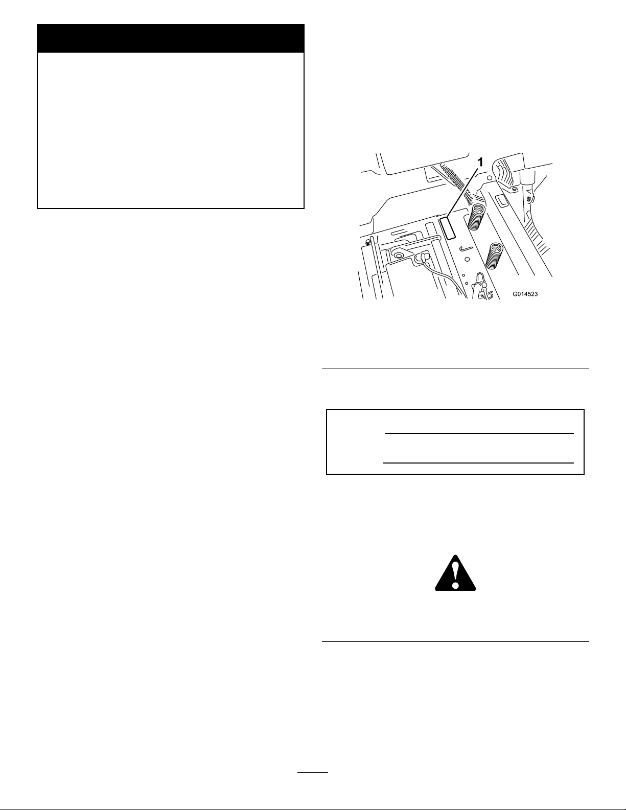
Wheneveryouneedservice,genuineToroparts,or
additionalinformation,contactanAuthorizedService
DealerorToroCustomerServiceandhavethemodel
andserialnumbersofyourproductready.Figure1
identiesthelocationofthemodelandserialnumbers
ontheproduct.Writethenumbersinthespace
provided.
g014523
Figure1
Undertheseat
1.Modelandserialnumberplate
Writetheproductmodelandserialnumbersinthe
spacebelow:
ModelNo.
SerialNo.
Thismanualidentiespotentialhazardsandhas
safetymessagesidentiedbythesafetyalertsymbol
(Figure2),whichsignalsahazardthatmaycause
seriousinjuryordeathifyoudonotfollowthe
recommendedprecautions.
Introduction
Thismachineisaride-on,rotary-bladelawnmower
intendedtobeusedbyhomeownersinresidential
applications.Itisprimarilydesignedforcuttinggrass
onwell-maintainedlawns.Itisnotdesignedforcutting
brush,mowinggrassandothergrowthalongside
highways,orforagriculturaluses.
Readthisinformationcarefullytolearnhowtooperate
andmaintainyourproductproperlyandtoavoid
injuryandproductdamage.Youareresponsiblefor
operatingtheproductproperlyandsafely .
YoumaycontactTorodirectlyatwww.Toro.com
forproductsafetyandoperationtrainingmaterials,
©2014—TheToro®Company
8111LyndaleAvenueSouth
Bloomington,MN55420
Figure2
1.Safetyalertsymbol.
Thismanualuses2wordstohighlightinformation.
Importantcallsattentiontospecialmechanical
informationandNoteemphasizesgeneralinformation
worthyofspecialattention.
2
g000502
Contactusatwww.Toro.com.
PrintedintheUSA.
AllRightsReserved
Page 3

Contents
Safety.......................................................................4
SafeOperatingPractices....................................4
SafetyandInstructionalDecals..........................6
ProductOverview....................................................11
Controls............................................................11
Operation................................................................13
AddingFuel......................................................13
CheckingtheEngine-OilLevel..........................14
BreakinginaNewMachine..............................14
ThinkSafetyFirst..............................................15
StartingtheEngine...........................................16
OperatingtheBlades........................................17
StoppingtheEngine.........................................17
Driving..............................................................17
StoppingtheMachine.......................................20
AdjustingtheHeight-of-Cut...............................20
AdjustingtheAnti-ScalpRollers........................20
PositioningtheSeat..........................................21
AdjustingtheMotion-ControlLevers.................21
PushingtheMachinebyHand..........................21
TransportingtheMachine.................................22
LoadingtheMachine........................................22
OperatingTips.................................................24
Maintenance...........................................................25
RecommendedMaintenanceSchedule(s)...........25
Pre-MaintenanceProcedures..............................26
RaisingtheSeat...............................................26
Lubrication..........................................................26
GreasingtheBearings......................................26
EngineMaintenance...........................................27
ServicingtheAirCleaner..................................27
ServicingtheEngineOil....................................28
ServicingtheSparkPlug...................................30
CleaningtheBlowerHousing............................31
FuelSystemMaintenance...................................31
ReplacingtheIn-LineFuelFilter.......................31
ElectricalSystemMaintenance...........................32
ChargingtheBattery.........................................32
ServicingtheFuses..........................................34
DriveSystemMaintenance..................................34
CheckingtheTirePressure...............................34
ReleasingtheElectricBrake.............................35
MowerMaintenance.............................................35
ServicingtheCuttingBlades.............................35
LevelingtheMowerDeck..................................38
RemovingtheMower........................................39
InstallingtheMower..........................................40
ReplacingtheGrassDeector..........................41
MowerBeltMaintenance......................................42
InspectingtheBelts..........................................42
ReplacingtheMowerBelt.................................42
Cleaning..............................................................43
WashingtheUndersideoftheMower................43
Storage...................................................................44
CleaningandStorage.......................................44
Troubleshooting......................................................45
Schematics.............................................................47
3
Page 4

Safety
Toreducethepotentialforinjury,comply
withthesesafetyinstructionsandalwayspay
attentiontothesafetyalertsymbol,whichmeans
CAUTION,WARNING,orDANGER-"personal
safetyinstruction."Failuretocomplywiththe
instructionmayresultinpersonalinjuryordeath.
SafeOperatingPractices
Thisproductiscapableofamputatinghandsand
feetandthrowingobjects.Alwaysfollowallsafety
instructionstoavoidseriousinjuryordeath.
ThefollowinginstructionsareadaptedfromANSI
standardB71.1-2012.Allthelanguagewithinthis
ANSIstandardappliestothismachine;however,
duetotheapplicationofthestandardacrossmany
differenttypesofproductssomestatementscan
seemgeneralormisleading.Intheseinstances,T oro
hasrenedthestatementtoconveythemeaningof
thestandardwhilebettermatchingtheproductthis
Operator'sManualpertains.Safetyinformationin
additiontotheinstructionsfoundintheANSIstandard
belowcanbefoundinToroRidingMowerSafetyat
theendofthissection.
GeneralOperation
•Read,understand,andfollowallinstructionsin
theoperator'smanualandonthemachinebefore
starting.
•Donotplacehandsorfeetnearrotatingpartsor
underthemachine.Keepclearofthedischarge
openingatalltimes.
•Allowonlyresponsibleadultswhoarefamiliarwith
theinstructionstooperatethemachine.
•Cleartheareaofobjectssuchasrocks,toys,wire,
etc.,whichcouldbepickedupandthrownbythe
blade.
•Besuretheareaisclearofotherpeoplebefore
mowing.Stopthemachineifanyoneentersthe
area.
•Nevercarrypassengers.
•Donotmowinreverseunlessabsolutely
necessary.Alwayslookdownandbehindbefore
andwhilebackingup.
•Beawareofthemowerdischargedirectionanddo
notpointitatanyone.Avoiddischargingmaterial
againstawallorobstruction.Materialmayricochet
backtowardtheoperator.Stoptheblade(s)when
crossinggravelsurfaces.
•Donotoperatethemachinewithoutdeector,
dischargecoverorentiregrasscollectionsystem
inplaceandworking.
•Bealert,slowdownandusecautionwhenmaking
turns.Lookbehindandtothesidebeforechanging
directions.
•Neverleavearunningmachineunattended.
Alwaysturnoffblades,setparkingbrake,stop
engine,andremovekeybeforedismounting.
•Turnoffbladeswhennotmowing.Stoptheengine,
waitforallpartstocometoacompletestopand
removethekeybeforecleaningthemachine,
removingthegrasscatcheroruncloggingthe
dischargechute.
•Operatethemachineonlyindaylightorgood
articiallight.
•Donotoperatethemachinewhileunderthe
inuenceofalcoholordrugs.
•Watchfortrafcwhenoperatingnearorcrossing
roadways.
•Useextracarewhenloadingorunloadingthe
machineintoatrailerortruck.
•Alwaysweareyeprotectionwhenoperatingthe
mower.
•Alwaysfollowtherecommendationsforany
applicationofcounterweights.
•Lightningcancausesevereinjuryordeath.If
lightningisseenorthunderisheardinthearea,do
notoperatethemachine;seekshelter.
SlopeOperation
Slopesareamajorfactorrelatedtolossofcontroland
tip-overaccidents,whichcanresultinsevereinjuryor
death.Operationonallslopesrequiresextracaution.
Ifyoucannotbackuptheslopeorifyoufeeluneasy
onit,donotmowit.
•Donotmowslopesgreaterthan15degrees.
•Watchforditches,holes,rocks,dips,andrises
thatchangetheoperatingangle,asroughterrain
couldoverturnthemachine.
•Choosealowgroundspeedsoyouwillnothave
tostopwhileoperatingonaslope.
•Donotmowslopeswhengrassiswet.Slippery
conditionsreducetractionandcouldcausesliding
andlossofcontrol.
•Alwayskeepthedrivewheelsengagedwhen
goingdownslopes.
•Reducespeedanduseextremecautiononslopes.
•Donotmakesuddenturnsorrapidspeedchanges.
•Removeormarkobstaclessuchasrocks,tree
limbs,etc.fromthemowingarea.Tallgrasscan
hideobstacles.
•Avoidsuddenstartswhenmowinguphillbecause
themowermaytipbackwards.
4
Page 5

•Beawarethatlossoftractionmayoccurgoing
downhill.Weighttransfertothefrontwheels
maycausedrivewheelstoslipandcauselossof
brakingandsteering.
•Alwaysavoidsuddenstartingorstoppingona
slope.Iftireslosetraction,stopthemachine,
disengagethebladesandproceedslowlyoffthe
slope.
•Useextremecarewithgrasscatchersorother
attachments.Thesecanchangethestabilityofthe
machineandcauselossofcontrol.
•Donottrytostabilizethemachinebyputtingyour
footontheground.
•Donotmowneardrop-offs,ditches,steepbanks
orwater.Wheelsdroppingoveredgescancause
rollovers,whichmayresultinseriousinjury,death
ordrowning.
•Useawalkbehindmowerand/orahandtrimmer
neardrop-offs,ditches,steepbanksorwater.
Children
Tragicaccidentscanoccuriftheoperatorisnot
alerttothepresenceofchildren.Childrenareoften
attractedtothemachineandthemowingactivity.
Neverassumethatchildrenwillremainwhereyou
lastsawthem.
•Keepchildrenoutofthemowingareaandunder
thewatchfulcareofanotherresponsibleadult,not
theoperator.
•Bealertandturnthemachineoffifchildrenenter
thearea.
•Beforeandwhilebackingorchangingdirection,
lookbehind,down,andside-to-sideforsmall
children.
•Nevercarrychildren,evenwiththebladesoff.
Theymayfalloffandbeseriouslyinjuredor
interferewithsafemachineoperation.
•Childrenwhohavebeengivenridesinthepast
maysuddenlyappearinthemowingareafor
anotherrideandberunoverorbackedoverby
themower.
•Neverallowchildrentooperatethemachine.
•Useextracarewhenapproachingblindcorners,
shrubs,trees,theendofafenceorotherobjects
thatmayobscurevision.
TowingSafety
•Donotattachtowedequipmentexceptatthehitch
point.
•Followtheattachmentmanufacturer's
recommendationforweightlimitsfortowed
equipmentandtowingonslopes.Towedweight
mustnotexceedtheweightofthemachine,
operator,andballast.Usecounterweightsor
wheelweightsasdescribedintheattachment,or
inthepullingmachineOperator’sManual.
•Neverallowchildrenorothersinorontowed
equipment.
•Onslopes,theweightofthetowedequipmentmay
causelossoftraction,increasedriskofrollover,
andlossofcontrol.Reducethetowedweightand
slowdown.
•Stoppingdistanceincreaseswiththeweightofthe
towedload.Travelslowlyandallowextradistance
tostop.
•Makewideturnstokeeptheattachmentclearof
themachine.
Service
SafeHandlingofGasoline:
Toavoidpersonalinjuryorpropertydamage,use
extracarewhenhandlinggasolineandotherfuels.
Theyareammableandthevaporsareexplosive.
•Extinguishallcigarettes,cigars,pipesandother
sourcesofignition.
•Useonlyanapprovedcontainer.
•Neverremovethegascaporaddfuelwhenthe
engineisrunning.Allowtheenginetocoolbefore
refueling.
•Neverrefuelthemachineindoors.
•Neverstorethemachineorfuelcontainerinside
wherethereisanopename,suchasneara
waterheaterorfurnace.
•Neverllcontainersinsideavehicleorona
truckortrailerwithaplasticliner.Alwaysplace
containersonthegroundawayfromyourvehicle
beforelling.
•Removegas-poweredequipmentfromthetruck
ortrailerandrefuelitontheground.Ifthisis
notpossible,thenrefuelsuchequipmentwitha
portablecontainer,ratherthanfromagasoline
dispensernozzle.
•Keepthenozzleincontactwiththerimofthefuel
tankorcontaineropeningatalltimesuntilthe
fuelingiscomplete.Donotuseanozzlelock-open
device.
•Iffuelisspilledonclothing,changeclothing
immediately.
•Neveroverllthefueltank.Replacegascapand
tightensecurely.
GeneralService:
•Neveroperateamachineinsideaclosedarea.
Engineexhaustcontainscarbonmonoxide,which
isanodorless,deadlypoisonthatcankillyou.
•Keepnutsandboltstight,especiallytheblade
attachmentbolts.Keepequipmentingood
condition.
5
Page 6
•Neverinterferewiththeintendedfunctionofa
safetydeviceortoreducetheprotectionprovided
byasafetydevice.Checktheirproperoperation
regularly.
movingpartsorallowobjectstobethrown.
Frequentlycheckcomponentsandreplace
withmanufacturers'recommendedparts,when
necessary.
•Keepthemachinefreeofgrass,leaves,orother
debrisbuild-up.Cleanupoilorfuelspillagefuel
soakeddebris.Allowthemachinetocoolbefore
storing.
•Stopandinspecttheequipmentifyoustrikean
object.Repair,ifnecessary,beforerestarting.
•Nevermakeanyadjustmentsorrepairswiththe
enginerunning.
•Grasscatchercomponentsaresubjecttowear,
damageanddeterioration,whichcouldexpose
SafetyandInstructionalDecals
Safetydecalsandinstructionsareeasilyvisibletotheoperatorandarelocatednearanyarea
ofpotentialdanger.Replaceanydecalthatisdamagedorlost.
•Mowerbladesaresharpandcancut.Wrapthe
blade(s)orwearthickly-paddedgloves,anduse
extracautionwhenservicingthem.
•Checkforproperbrakeoperationfrequently.
Adjustandserviceasrequired.
•Maintainorreplacesafetyandinstructiondecals
asnecessary.
•UseonlygenuineT ororeplacementpartsto
ensurethatoriginalstandardsaremaintained.
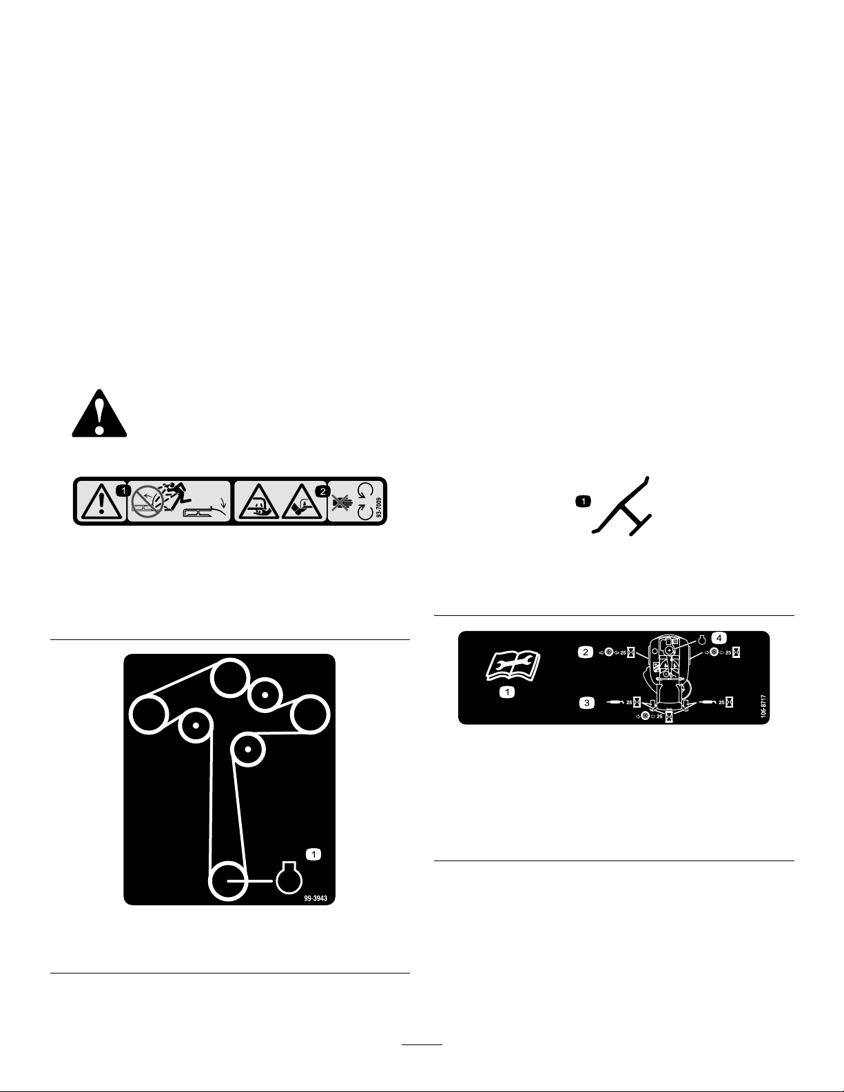
93-7009
1.Warning—don'toperatethemowerwiththedeectorupor
removed;keepthedeectorinplace.
2.Cutting/dismembermenthazardofhandorfoot,mower
blade—stayawayfrommovingparts.
99-3943
decal93-7009
Manufacturer'sMark
1.Indicatesthebladeisidentiedasapartfromtheoriginal
machinemanufacturer.
106-8717
1.Readtheinstructionsbeforeservicingorperforming
maintenance.
2.Checktirepressureevery25operatinghours.
3.Greaseevery25operatinghours.
4.Engine
decal99-3943
decaloemmarkt
decal106-8717
1.Engine
6
Page 7
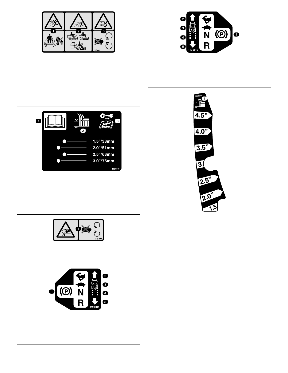
decal110-6691
110-6691
119-8815
decal119-8815
1.Thrownobjecthazard—keepbystandersasafedistance
fromthemachine.
2.Thrownobjecthazard,mower—donotoperatewithoutthe
deector,dischargecover,orgrasscollectionsystemin
place.
3.Cutting/dismembermentofhandorfoot—stayawayfrom
movingparts.
112-9840
1.ReadtheOperator's
Manual.
2.Height-of-cut
3.Removetheignitionkey
andreadtheinstructions
beforeservicingor
performingmaintenance.
1.Parkingposition4.Neutral
2.Fast5.Reverse
3.Slow
decal112-9840
decal119-8870
119-8870
114-1606
1.Entanglementhazard,belt—keepallguardsinplace.
119-8814
1.Parkingposition4.Neutral
2.Fast5.Reverse
3.Slow
1.Height-of-cut
decal114-1606
decal119-8814
7
Page 8
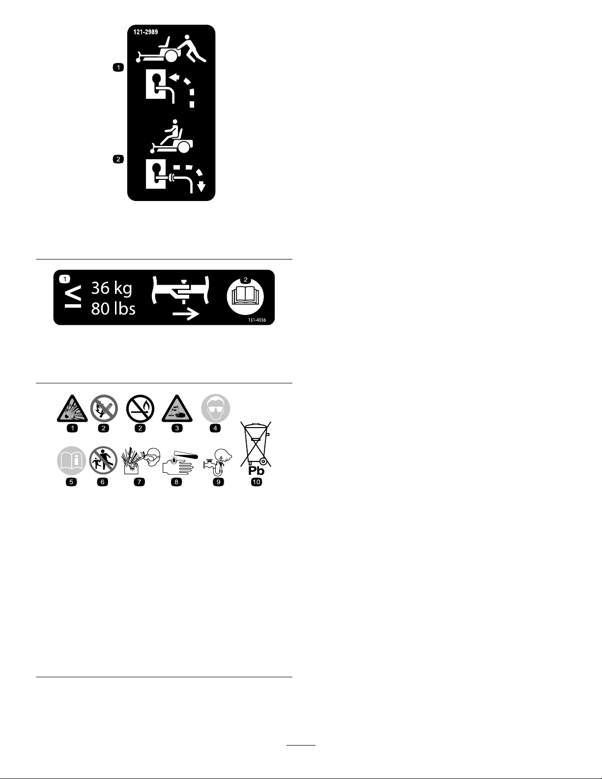
decal121-2989b
121-2989
1.Bypassleverpositionfor
pushingthemachine
131-4036
1.Maximumdrawbarpull36
kg(80lb)
BatterySymbols
Someorallofthesesymbolsareonyourbattery
2.Bypassleverpositionfor
operatingthemachine
decal131-4036
2.ReadtheOperator's
Manual.
decalbatterysymbols
1.Explosionhazard
2.Nore,opename,or
6.Keepbystandersasafe
7.Weareyeprotection;
smoking.
3.Causticliquid/chemical
8.Batteryacidcancause
burnhazard
4.Weareyeprotection9.Flusheyesimmediately
5.ReadtheOperator's
10.Containslead;donot
Manual.
distancefromthebattery.
explosivegasescan
causeblindnessandother
injuries
blindnessorsevereburns.
withwaterandgetmedical
helpfast.
discard.
8
Page 9

decal131-3947
131–3947
1.Trim—slow
3.Mow—fast
2.Tow—medium
decal131-4162
131-4162
1.Fast
2.Slow
3.Powertake-off
9
Page 10
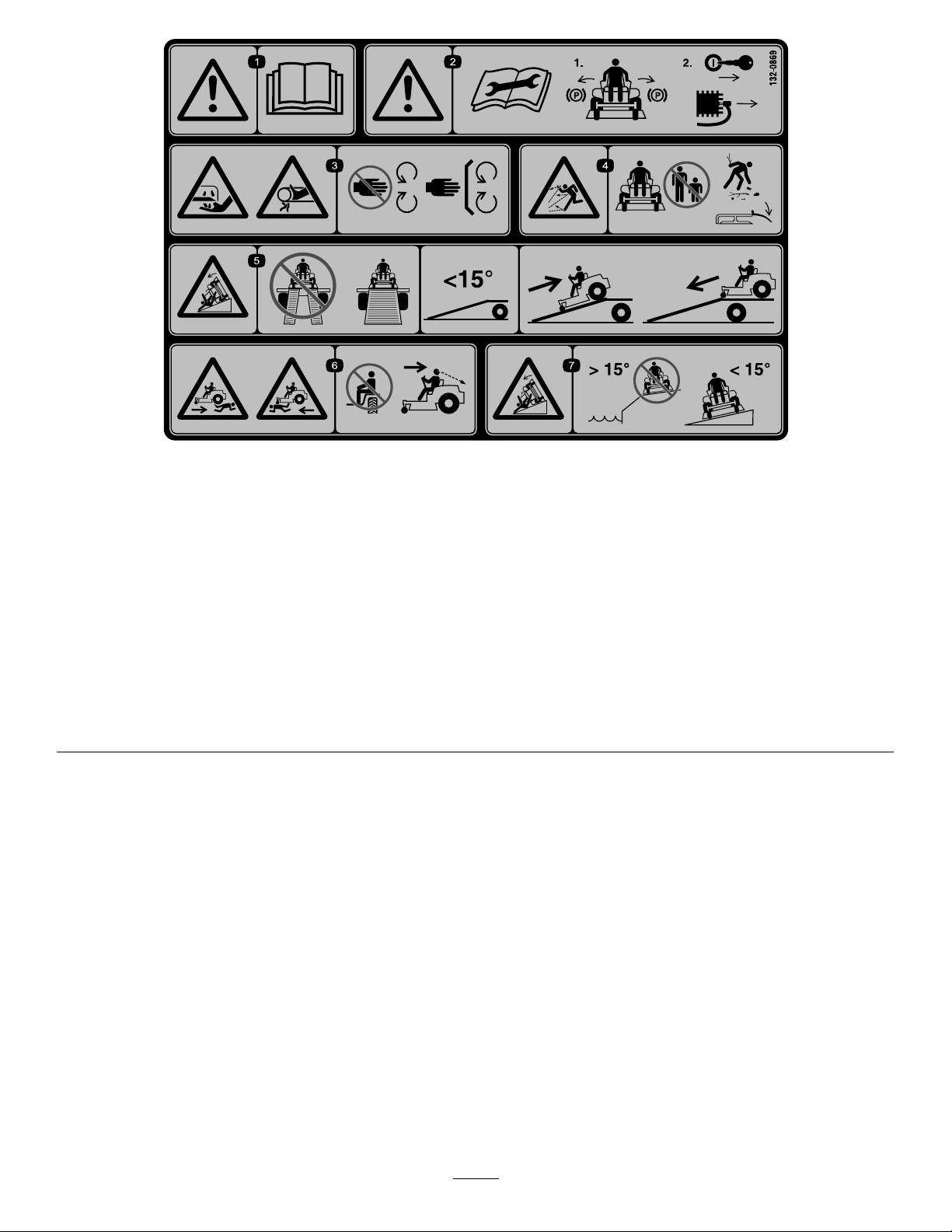
decal132-0869
132-0869
1.Warning—readthe
Operator'sManual.
2.Warning—beforeservicing,
engagetheparkingbrake,
removethekeyandthe
sparkplugconnection.
3.Cuttinghazardofhand,
mowerblade;pinching
hazardofhand,belt—keep
handsandfeetawayfrom
movingparts;keepall
guardsandshieldsinplace.
4.Thrownobject
hazard—keepbystanders
awayfromthemachine;
removedebrisfromthe
areabeforemowing;keep
thedeectorshielddown.
5.Ramptipping
hazard—whenloading
ontoatrailer,donotuse
dualramps;onlyusea
singlerampwideenough
forthemachineandthat
hasaninclinelessthan
15degrees;backupthe
ramp(inreverse)anddrive
forwardofftheramp.
6.Bodilyharmhazard—no
riders;lookbehindyou
whenmowinginreverse.
7.Tippinghazardon
slopes—donotuseon
slopesnearopenwater;do
notuseonslopesgreater
than15degrees.
10
Page 11
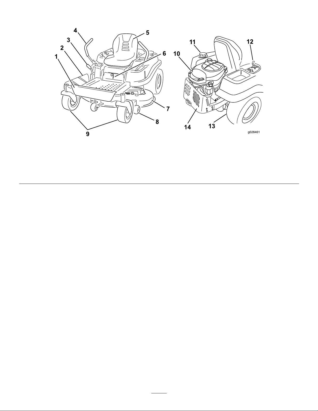
ProductOverview
g028461
Figure3
1.Footrest
2.Deector6.SmartSpeed™lever
3.Height-of-cutlever
4.Motion-controllevers8.Anti-scalproller
5.Operatorseat
7.Mowerdeck
Controls
BecomefamiliarwithallofthecontrolsinFigure3
andFigure4beforeyoustarttheengineandoperate
themachine.
9.Frontcasterwheel13.Reardrivewheel
10.Engine14.Engineguard
11.Fuel-tankcap
12.Controlpanel
11
Page 12
ControlPanel
Motion-ControlLeversandPark
Position
Themotion-controlleversarespeed-sensitivecontrols
ofindependent-wheelmotors.Movingaleverforward
orbackwardturnsthewheelonthesamesideforward
orinreverse;wheelspeedisproportionaltothe
amounttheleverismoved.Movethecontrollevers
outwardfromthecentertotheparkposition,and
exitthemachine(Figure13).Alwayspositionthe
motion-controlleversintotheparkpositionwhenyou
stopthemachineorleaveitunattended.
SmartSpeed™ControlSystem
Lever
TheSmartSpeed™Control-Systemlever,located
belowtheoperatingposition,givestheoperatora
choicetodrivethemachineat3speedranges—trim,
tow,andmow(Figure5).
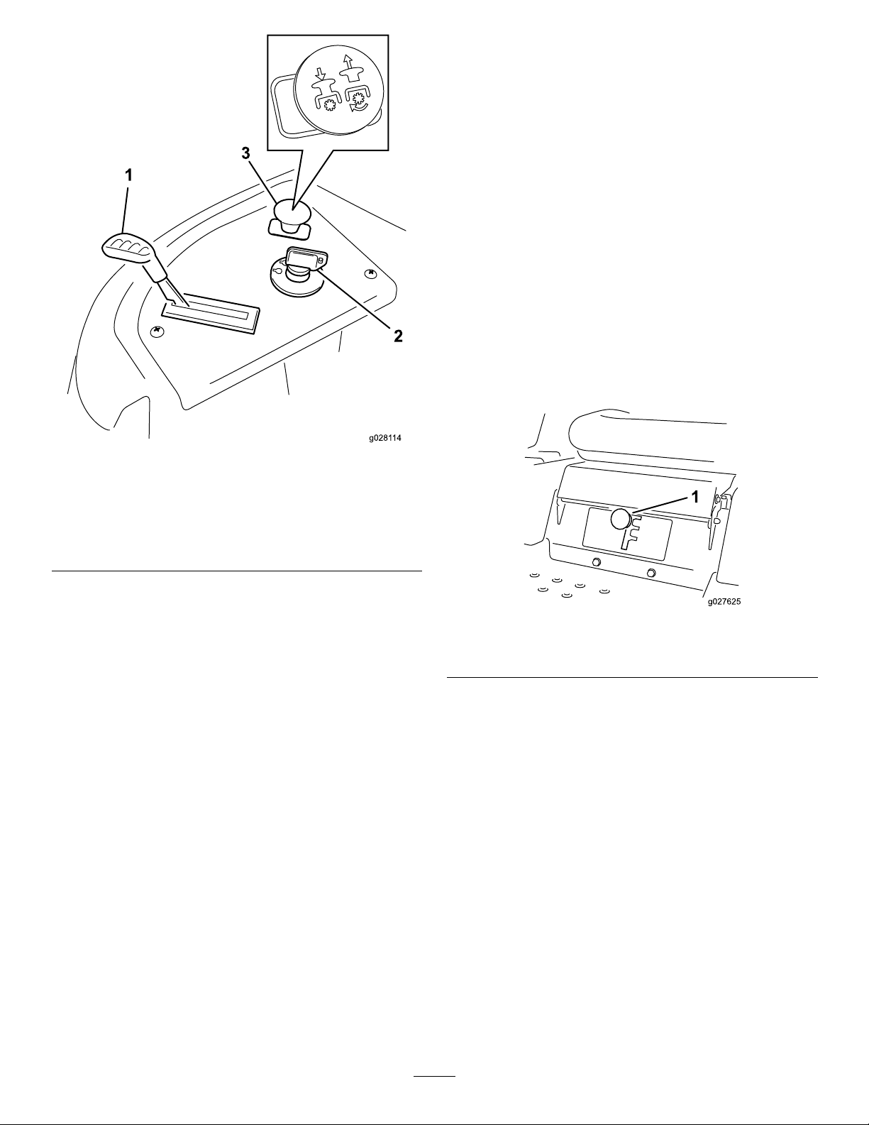
g028114
Figure4
1.Throttle3.Blade-controlswitch
(powertake-off)
2.Ignitionswitch
IgnitionSwitch
Theignitionswitchhas3positions:Off,Run,and
Start.ThekeywillturntoStartandmovebacktoRun
uponrelease.TurningthekeytotheOffpositionwill
stoptheengine;however,alwaysremovethekey
whenleavingthemachinetopreventsomeonefrom
accidentallystartingtheengine(Figure4).
ThrottleControl
Thethrottlecontrolstheenginespeed,andithasa
continuous-variablesettingfromSlowtoFast(Figure
4).
Blade-ControlSwitch(Power
Take-off)
g027625
Figure5
1.Smart-speedlever
Fuel-PresenceWindow
Thefuelwindowlocatedontheleft-handsideof
themachinecanbeusedtoverifythepresenceof
gasolineinthetank(Figure6).
Theblade-controlswitch,representedbyapower
take-off(PTO)symbol,engagesanddisengages
powertothemowerblades(Figure4).
12
Page 13

Figure6
1.Fuel-presencewindow
Height-of-CutLever
Theheight-of-cutleverallowstheoperatortolower
andraisethedeckfromtheseatedposition.Whenthe
leverismovedup(towardtheoperator),thedeckis
raisedfromtheground,andwhenmoveddown(away
fromtheoperator),itisloweredtowardtheground.
Onlyadjusttheheight-of-cutwhilethemachineisnot
moving(Figure17).
Operation
Note:Determinetheleftandrightsidesofthe
machinefromthenormaloperatingposition.
AddingFuel
•Forbestresults,useonlyclean,fresh(lessthan
30daysold),unleadedgasolinewithanoctane
ratingof87orhigher((R+M)/2ratingmethod).
•Ethanol:Gasolinewithupto10%ethanol
g014521
(gasohol)or15%MTBE(methyltertiarybutyl
ether)byvolumeisacceptable.Ethanoland
MTBEarenotthesame.Gasolinewith15%
ethanol(E15)byvolumeisnotapprovedforuse.
Neverusegasolinethatcontainsmorethan
10%ethanolbyvolume,suchasE15(contains
15%ethanol),E20(contains20%ethanol),orE85
(containsupto85%ethanol).Usingunapproved
gasolinemaycauseperformanceproblemsand/or
enginedamagewhichmaynotbecoveredunder
warranty.
•Donotusegasolinecontainingmethanol.
•Donotstorefueleitherinthefueltankorfuel
containersoverthewinterunlessafuelstabilizer
isused.
•Donotaddoiltogasoline.
DANGER
Incertainconditions,gasolineisextremely
ammableandhighlyexplosive.Areor
explosionfromgasolinecanburnyouand
othersandcandamageproperty.
•Fillthefueltankoutdoors,inanopenarea,
whentheengineiscold.Wipeupany
gasolinethatspills.
•Neverllthefueltankinsideanenclosed
trailer.
•Donotllthefueltankcompletelyfull.Add
gasolinetothefueltankuntilthelevelis6
to13mm(1/4to1/2inch)belowthebottom
ofthellerneck.Thisemptyspaceinthe
tankallowsgasolinetoexpand.
•Neversmokewhenhandlinggasoline,and
stayawayfromanopenameorwhere
gasolinefumesmaybeignitedbyaspark.
•Storegasolineinanapprovedcontainer
andkeepitoutofthereachofchildren.
Neverbuymorethana30-daysupplyof
gasoline.
•Donotoperatewithoutentireexhaust
systeminplaceandinproperworking
condition.
13
Page 14
DANGER
Incertainconditionsduringfueling,static
electricitycanbereleasedcausingaspark
whichcanignitethegasolinevapors.Are
orexplosionfromgasolinecanburnyouand
othersandcandamageproperty.
Addthecorrectamountofgasstabilizer/conditioner
tothegas.
Note:Afuelstabilizer/conditionerismosteffective
whenmixedwithfreshgasoline.T ominimizethe
chanceofvarnishdepositsinthefuelsystem,use
fuelstabilizeratalltimes.
•Alwaysplacegasolinecontainersonthe
groundawayfromyourvehiclebefore
lling.
•Donotllgasolinecontainersinsidea
vehicleoronatruckortrailerbedbecause
interiorcarpetsorplastictruckbedliners
mayinsulatethecontainerandslowthe
lossofanystaticcharge.
•Whenpractical,removegas-powered
equipmentfromthetruckortrailerand
refueltheequipmentwithitswheelsonthe
ground.
•Ifthisisnotpossible,thenrefuelsuch
equipmentonatruckortrailerfroma
portablecontainer,ratherthanfroma
gasolinedispensernozzle.
•Ifagasolinedispensernozzlemustbe
used,keepthenozzleincontactwiththe
rimofthefueltankorcontaineropeningat
alltimesuntilfuelingiscomplete.
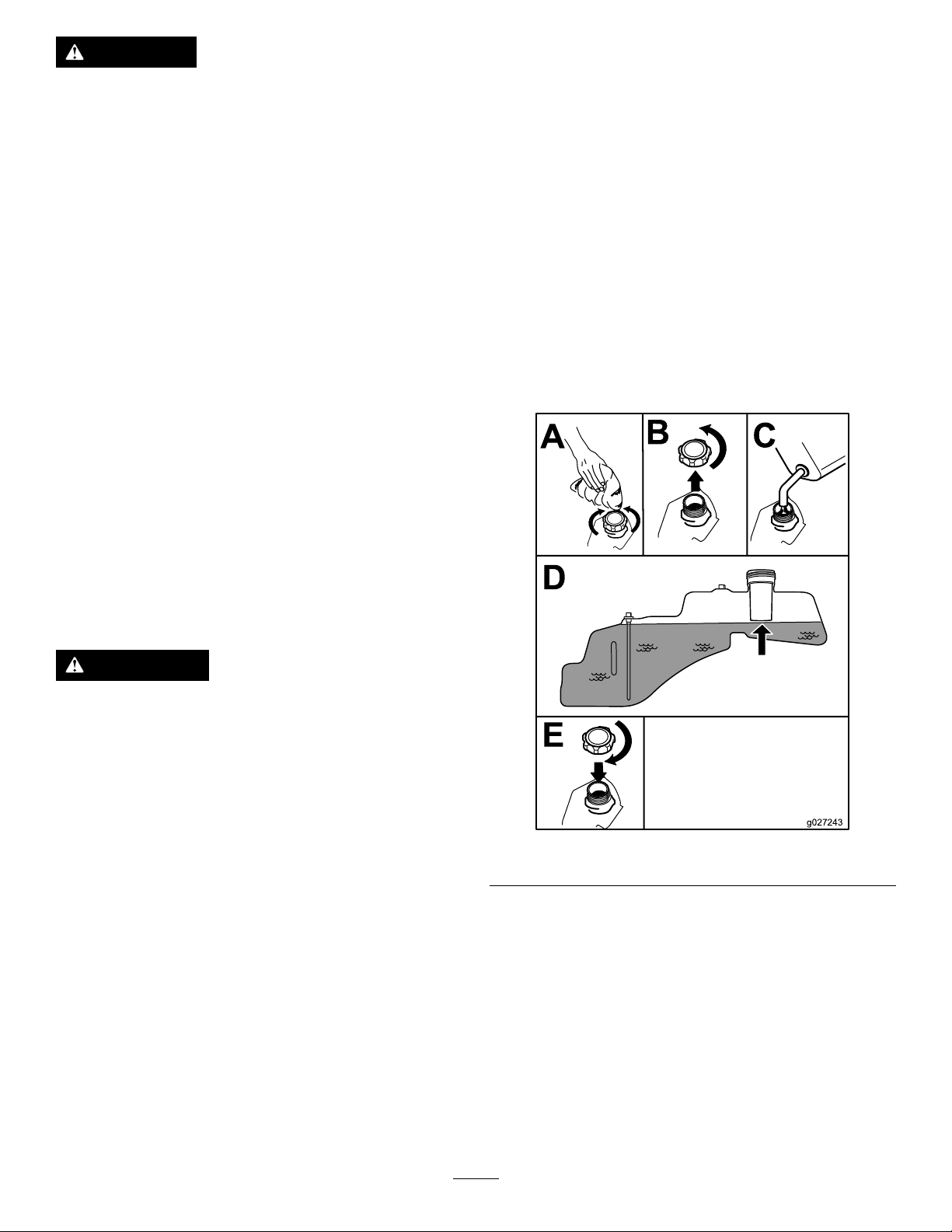
FillingtheFuelTank
Note:Ensurethattheengineisshutoffandthe
motioncontrolsareintheparkedposition.
Note:Y oucanusethefuelwindowtoverifythe
presenceofgasolinebeforellingthetank(Figure7).
Important:Donotoverllfueltank.Fillthefuel
tanktothebottomofthellerneck.Theempty
spaceinthetankallowsthefueltoexpand.
Overllingmayresultinfuelleakage,damageto
theengine,ordamagetotheemissionssystem.
WARNING
Gasolineisharmfulorfatalifswallowed.
Long-termexposuretovaporscancause
seriousinjuryandillness.
•Avoidprolongedbreathingofvapors.
•Keepfaceawayfromnozzleandgastank
orconditionerbottleopening.
•Avoidcontactwithskin;washoffspillage
withsoapandwater.
UsingStabilizer/Conditioner
Useafuelstabilizer/conditionerinthemachineto
providethefollowingbenets:
•Keepsgasolinefreshduringstorageof90daysor
less.Forlongerstorageitisrecommendedthat
thefueltankbedrained.
•Cleanstheenginewhileitruns
•Eliminatesgum-likevarnishbuildupinthefuel
system,whichcauseshardstarting
Important:Donotusefueladditives
containingmethanolorethanol.
g027243
Figure7
CheckingtheEngine-Oil Level
Beforeyoustarttheengineandusethemachine,
checktheoillevelintheenginecrankcase;referto
CheckingtheEngine-OilLevel(page28).
BreakinginaNewMachine
Newenginestaketimetodevelopfullpower.Mower
decksanddrivesystemshavehigherfrictionwhen
14
Page 15
new,placingadditionalloadontheengine.Allow
40to50hoursofbreak-intimefornewmachinesto
developfullpowerandbestperformance.
ThinkSafetyFirst
OperatingSafety
Pleasecarefullyreadallofthesafetyinstructionsand
decalsinthesafetysection.Knowingthisinformation
couldhelpyou,yourfamily ,pets,orbystandersavoid
injury.
DANGER
Mowingonwetgrassorsteepslopescan
causeslidingandlossofcontrol.
Wheelsdroppingoveredgescancause
rollovers,whichmayresultinseriousinjury,
death,ordrowning.
Alossoftractionisalossofsteeringcontrol.
Toavoidlossofcontrolandpossibilityof
rollover:
•Donotmowneardrop-offsornearwater.
•Donotmowslopesgreaterthan15degrees.
•Reducethespeedanduseextremecaution
onslopes.
•Whenmowingslopes,graduallyworkfrom
lowertohigherareasontheincline.
•Avoidsuddenturnsorrapidspeed
changes.
•Turnup,intoaninclinewhenchanging
directionsonslopes.T urningdownthe
slopereducestraction.
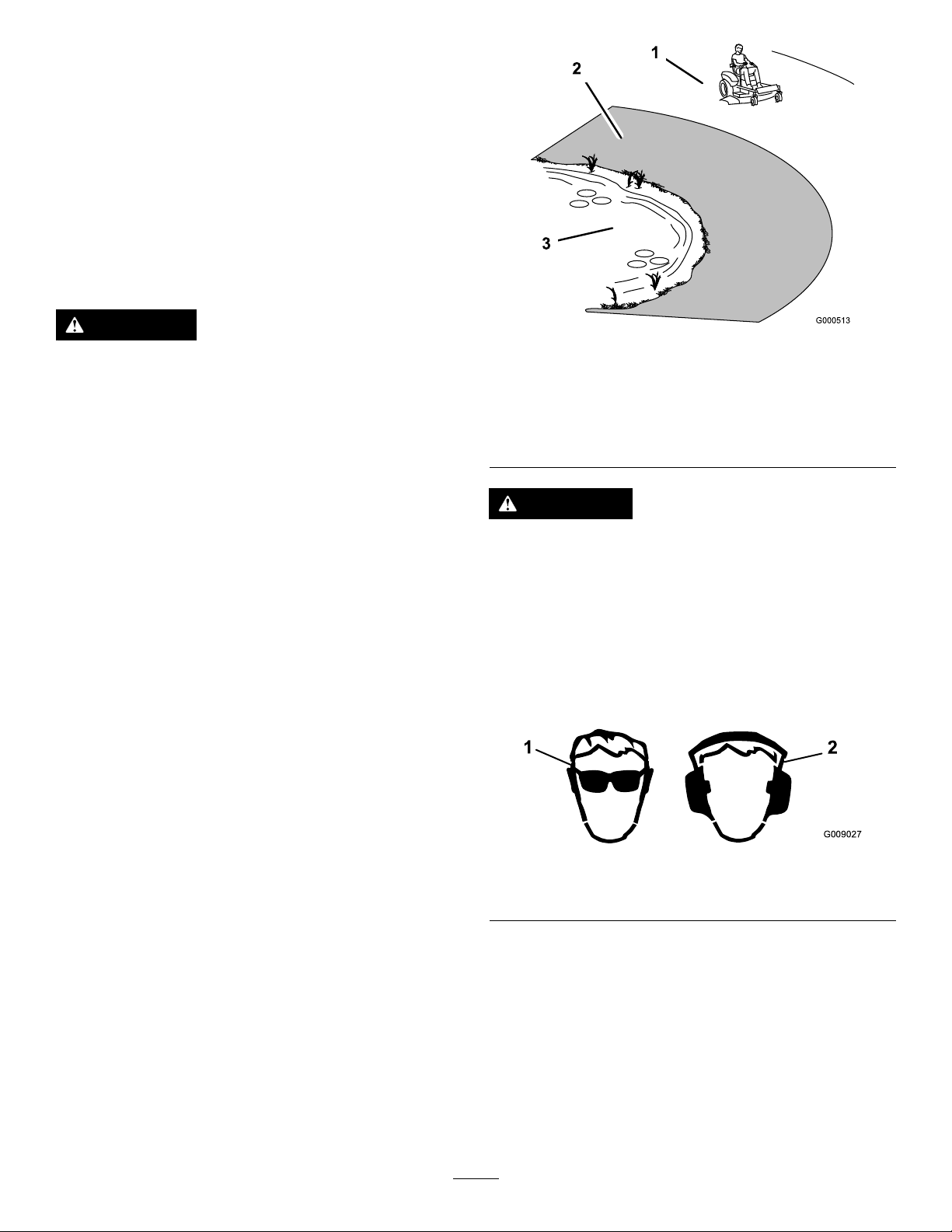
Figure8
1.Safezone—usethe
TimeCutterhere
2.Useawalk-behindmower
and/orhandtrimmernear
drop-offsandwater.
3.Water
CAUTION
Thismachineproducessoundlevelsin
excessof85dBAattheoperatorsearandcan
causehearinglossthroughextendedperiods
ofexposure.
Wearhearingprotectionwhenoperatingthis
machine.
Theuseofprotectiveequipmentforeyes,ears,
hands,feet,andheadisrecommended.
g000513
•Attachmentschangethehandling
characteristicsofthemachine.Useextra
cautionwhenusingattachmentswiththe
machine.
15
1.Wearsafetyglasses
g009027
Figure9
2.Wearhearingprotection
Page 16

Understandingthe
Safety-InterlockSystem
WARNING
Ifsafety-interlockswitchesaredisconnected
ordamaged,themachinecouldoperate
unexpectedlycausingpersonalinjury.
11.Starttheengine.
12.Whiletheengineisrunning,movethe
motion-controlleverstothecenter,unlocked
position,engagetheblade-controlswitch,and
riseslightlyfromtheseat.
Note:Theengineshouldstop.
•Donottamperwiththeinterlockswitches.
•Checktheoperationoftheinterlock
switchesdaily,andreplaceanydamaged
switchesbeforeoperatingthemachine.
Thesafety-interlocksystemisdesignedtopreventthe
enginefromstartingunless:
•Thebladesaredisengaged.
•Themotion-controlleversareintheparkposition.
Thesafety-interlocksystemalsoisdesignedtostop
theenginewheneverthecontrolleversareoutofthe
parkpositionandyourisefromtheseat.
TestingtheSafety-Interlock
System
Testthesafety-interlocksystembeforeyouusethe
machineeachtime.Ifthesafetysystemdoesnot
operateasdescribedbelow,haveanAuthorized
ServiceDealerrepairthesafetysystemimmediately .
1.Whilesittingontheseat,withthecontrollevers
inparkposition,andmovetheblade-control
switchtoOn.
2.Trystartingtheengine;theengineshouldnot
crank.
3.Whilesittingontheseat,movetheblade-control
switchtoOff.
4.Moveeithermotion-controllevertothecenter,
unlockedposition.
5.Trystartingtheengine;theengineshouldnot
crank.
6.Repeatwiththeothermotion-controllever.
7.Whilesittingontheseat,movetheblade-control
switchtoOff,andlockthemotion-controllevers
intheparkposition.
8.Starttheengine.
9.Whiletheengineisrunning,engagethe
blade-controlswitch,andriseslightlyfromthe
seat.
StartingtheEngine
Important:Donotengagethestarterformore
than10secondsatatime.Iftheenginefailsto
start,allowa60secondcool-downperiodbetween
attempts.Failuretofollowtheseinstructionscan
damagethestartermotor.
g027578
Figure10
Note:Theengineshouldstop.
10.Whilesittingontheseat,movetheblade-control
switchtoOff,andlockthemotion-controllevers
intheparkposition.
16
Page 17

OperatingtheBlades
StoppingtheEngine
Theblade-controlswitch,representedbyapower
take-off(PTO)symbol,engagesanddisengages
powertothemowerblades.Thisswitchcontrols
powertoanyattachmentsthatdrawpowerfromthe
engine,includingthemowerdeckandcuttingblades.
EngagingtheBlades
Important:Donotengagethebladeswhen
parkedintallgrass.Beltorclutchdamagecan
occur.
Note:Alwaysengagethebladeswiththethrottlein
theFastposition(Figure11).
1.Disengagethebladesbymovingthe
blade-controlswitchtoOff(Figure12).
2.Movethethrottlelevertobetweenthehalfand
fullthrottleposition.
3.TurntheignitionkeytoOffandremovethekey.
Driving
Drivingthemachinebenetsfromanunderstanding
ofwhatzero-turn-radiusmowermeans.Thedrive
wheelsturnindependently,poweredbyhydraulic
motorsoneachaxle;henceonesidecanturnin
reversewhiletheotherturnsforwardcausingthe
machinetospinratherthanturn.Thisvastlyimproves
themachinemaneuverabilitybutmayrequiresome
adjustmentiftheoperatorisunfamiliar.
WARNING
Themachinecanspinveryrapidly.The
operatormaylosecontrolofthemachine
andcausepersonalinjuryordamagetothe
machine.
Figure11
DisengagingtheBlades
Figure12
1.Controlpanel2.Blade-controlswitch—Off
•Usecautionwhenmakingturns.
•Slowthemachinedownbeforemaking
sharpturns.
g027582
g027247
Thethrottlecontrolregulatestheenginespeedas
measuredinrpm(revolutionsperminute).Placing
thethrottlecontrolintheFastpositioncanbebestfor
performance.Formostapplications,operatinginthe
full-throttlepositionisdesirable.
17
Page 18

UsingtheSmartSpeed
System
TM
Control
Figure13
1.Park(brake)position
2.Center,unlockposition5.FrontoftheMachine
3.Forward
4.Backward
TheSmartSpeed
TM
Control-Systemlever,located
belowtheoperatingposition(Figure14),givesthe
operatorachoicetodrivethemachineat3ground
speedranges—trim,tow,andmow.
g027625
Figure14
1.Smartspeedlever
g004532
Tochangespeeds,dothefollowing:
1.Movethemotioncontrolleverstoneutraland
outwardtotheparkposition.
2.Disengagethebladecontrolswitch
3.Adjustthelevertothedesiredposition.
Thefollowingareonlyrecommendationsforuse.
Adjustmentswillvarybygrasstype,moisturecontent,
andtheheightofthegrass.
Suggested
uses:
ParkingX
Heavy,wet
grass
TrainingX
BaggingX
MulchingX
Normal
mowing
Transport
TrimTowMow
X
X
X
Trim
Thisisthelowestspeed.Thesuggestedusesforthis
speedareasfollows:
•Parking
•Heavy,wetgrassmowingconditions
•Training
Tow
18
Page 19

Thisisthemediumspeed.Thesuggestedusesfor
thisspeedareasfollows:
•Bagging
•Mulching
Mow
Thisisthefastestspeed.Thesuggestedusesforthis
speedareasfollows:
•Normalmowing
•Transportingthemachine
DrivingForward
1.Movetheleverstothecenter,unlockedposition.
2.T ogoforward,slowlypushthemotion-control
leversforward(Figure13).
g008952
Figure15
Togostraight,applyequalpressuretoboth
motion-controllevers(Figure13).
Toturn,releasepressureonthemotion-control
levertowardthedirectionyouwanttoturn
(Figure13).
Thefartheryoumovethemotion-controllevers
ineitherdirection,thefasterthemachinewill
moveinthatdirection.
Tostop,pullthemotion-controlleverstoneutral.
19
Page 20

DrivingBackward
Note:Alwaysusecautionwhenbackingupand
turning.
1.Movetheleverstothecenter,unlockedposition.
2.T ogobackward,lookbehindyouanddown,
asyouslowlypullthemotion-controllevers
rearward(Figure16).
AdjustingtheHeight-of-Cut
Thetransportpositionisthehighestheight-of-cut
positionorcuttingheight(115mm(4.5inches))as
showninFigure17.
Figure16
Togostraight,applyequalpressuretoboth
motion-controllevers(Figure16).
Toturn,releasethepressureonthe
motion-controllevertowardthedirectionyou
wanttoturn.
Tostop,pushthemotion-controlleversto
neutral.
StoppingtheMachine
Tostopthemachine,movethemotion-controllevers
toneutralandoutwardtotheparkposition,disengage
theblade-controlswitch,ensurethethrottleisbetween
halfandfullthrottle,andturntheignitionkeytooff.
Note:Remembertoremovethekeyfromtheignition
switch.
WARNING
Childrenorbystandersmaybeinjuredifthey
moveorattempttooperatethemowerwhile
itisunattended.
Alwaysremovetheignitionkeyandmove
themotion-controlleversoutwardtothe
parkpositionwhenleavingthemachine
unattended,evenifjustforafewminutes.
g008953
g028025
Figure17
AdjustingtheAnti-Scalp Rollers
Wheneveryouchangetheheight-of-cut,itis
recommendedtoadjusttheheightoftheanti-scalp
rollers.
Note:Adjusttheanti-scalprollerssotherollersdo
nottouchthegroundinnormal,atmowingareas.
1.Disengagethebladecontrolswitch(PTO),move
themotioncontrolleverstotheneutrallock
positionandsettheparkingbrake.
2.Stoptheengine,removethekey,andwait
forallmovingpartstostopbeforeleavingthe
operatingposition.
3.Adjusttheanti-scalprollersasshowninFigure
18tomatchtheclosestheight-of-cutposition.
20
Page 21

Figure18
1.Anti-scalproller3.FlangeNut
2.Bolt4.Holespacing
PositioningtheSeat
Adjustingthe Motion-ControlLevers
AdjustingtheHeight
Themotion-controlleverscanbeadjustedhigheror
lowerformaximumoperatorcomfort(Figure20).
g010233
g027252
Figure20
Figure19
AdjustingtheTilt
Themotion-controlleverscanbetiltedforeoraftfor
maximumoperatorcomfort.
1.Loosentheupperboltholdingthecontrollever
tothecontrol-armshaft.
2.Loosenthelowerboltjustenoughtopivotthe
controlleverforeoraft(Figure20).Tightenboth
boltstosecurethecontrolinthenewposition.
3.Repeattheadjustmentfortheoppositecontrol
lever.
g027249
PushingtheMachineby Hand
Important:Alwayspushthemachinebyhand.Do
nottowthemachine,becausedamagemayoccur.
Thismachinehasanelectric-brakemechanism,and
topushthemachine,theignitionkeyneedstobein
theRunposition.Thebatteryneedstobecharged
andfunctioningfortheelectricbraketobedisengage.
21
Page 22

PushingtheMachine
1.Parkthemachineonalevelsurface,and
disengagetheblade-controlswitch.
2.Movethemotion-controlleversoutwardto
theparkposition,stoptheengine,andwait
forallmovingpartstostopbeforeleavingthe
operatingposition.
3.Locatethebypassleversontheframeonboth
sidesoftheengine.
4.Movethebypassleversforwardthroughthekey
holeanddowntolocktheminplace(Figure21).
Note:Ensurethisisdoneforeachlever.
5.Movethemotion-controlleversinwardtothe
neutralpositionandturntheignitionkeytothe
Runposition.
Note:Donotstartthemachine.
Note:Themachineisnowabletobepushed
byhand.
TransportingtheMachine
Useaheavy-dutytrailerortrucktotransportthe
machine.Ensurethatthetrailerortruckhasall
necessarybrakes,lighting,andmarkingasrequired
bylaw.Pleasecarefullyreadallthesafetyinstructions.
Knowingthisinformationcouldhelpyou,yourfamily,
pets,orbystandersavoidinjury.
WARNING
Drivingonthestreetorroadwaywithoutturn
signals,lights,reectivemarkings,oraslow
movingvehicleemblemisdangerousandcan
leadtoaccidentscausingpersonalinjury.
Donotdrivemachineonapublicstreetor
roadway.
Totransportthemachine:
1.Ifusingatrailer,connectittothetowingvehicle
andconnectthesafetychains.
2.Ifapplicable,connectthetrailerbrakes.
Figure21
1.Bypass-leverlocations
2.Leverpositionfor
operatingthemachine
6.Whennished,ensurethatthekeyhasbeen
returnedtotheStoppositiontoavoiddraining
thebatterycharge.
3.Leverpositionforpushing
themachine
Note:Ifthemachinefailstomove,theelectricbrake
maystillbeengaged.Ifnecessary,theelectricbrake
canbereleasedmanually;refertoReleasingthe
ElectricBrake(page35).
3.Loadthemachineontothetrailerortruck.
4.Stoptheengine,removethekey,setthebrake,
andclosethefuelvalve.
5.Tiedownthemachinenearthefrontcaster
wheelsandtherearbumper(Figure22).
g017303
g027708
Figure22
LoadingtheMachine
Useextremecautionwhenloadingorunloading
machinesontoatraileroratruck.Useafull-width
rampthatiswiderthanthemachineforthisprocedure.
Backuprampsanddriveforwarddownramps(Figure
23).
OperatingtheMachine
Movethebypassleversrearwardthroughthekeyhole
anddowntolocktheminplaceasshowninFigure21.
Note:Ensurethisisdoneforeachlever.
22
Page 23

Figure23
g027995
1.Backupramps
2.Driveforwarddownramps
Important:Donotusenarrowindividualramps
foreachsideofthemachine.
Ensuretherampislongenoughsothattheanglewith
thegrounddoesnotexceed15degrees(Figure24).
Onatground,thisrequiresaramptobeatleastfour
times(4X)aslongastheheightofthetrailerortruck
bedtotheground.Asteeperanglemaycausemower
componentstogetcaughtastheunitmovesfromthe
ramptothetrailerortruck.Steeperanglesmayalso
causethemachinetotiporlosecontrol.Ifloadingon
ornearaslope,positionthetrailerortrucksothatitis
onthedownsideoftheslopeandtherampextends
uptheslope.Thiswillminimizetherampangle.
WARNING
Loadingamachineontoatrailerortruck
increasesthepossibilityoftip-overandcould
causeseriousinjuryordeath.
•Useextremecautionwhenoperatinga
machineonaramp.
•Useonlyafull-widthramp;donotuse
individualrampsforeachsideofthe
machine.
•Donotexceeda15-degreeanglebetween
therampandthegroundorbetweenthe
rampandthetrailerortruck.
1.Full-widthrampinstowed
position
2.Sideviewoffull-width
rampinloadingposition
3.Notgreaterthan
15degrees
g027996
Figure24
4.Rampisatleastfourtimes
(4X)aslongastheheight
ofthetrailerortruckbed
totheground
5.H=heightofthetraileror
truckbedtotheground
6.Trailer
•Ensurethelengthoframpisatleastfour
times(4X)aslongastheheightofthe
trailerortruckbedtotheground.Thiswill
ensurethatrampangledoesnotexceed15
degreesonatground.
•Backuprampsanddriveforwarddown
ramps.
•Avoidsuddenaccelerationordeceleration
whiledrivingthemachineonarampas
thiscouldcausealossofcontrolora
tip-oversituation.
23
Page 24

OperatingTips
rstmowatahighcuttingheight,thenmowagain2
dayslateratalowerheightsetting.
UsingtheFastThrottleSetting
Forbestmowingandmaximumaircirculation,operate
theengineattheFastthrottleposition.Airisrequired
tothoroughlycutgrassclippings,sodonotsetthe
height-of-cutsolowastototallysurroundthemower
byuncutgrass.Alwaystrytohaveonesideofthe
mowerfreefromuncutgrass,whichallowsairtobe
drawnintothemower.
UsingtheSmartSpeed™Control
System
TheSmartSpeed™Control-Systemlever,located
belowtheoperatingposition,givestheoperatora
choicetodrivethemachineat3speedranges—trim,
mow,andtow.Anoperatorcanbenetfromthetrim
speedsettingwhenmaneuveringthemachineintight
spacesoroperatingarounddelicatelandscapes.The
trimsettingcanalsobeusedtooperatethemachine
atahighthrottlesettingandbladespeed,whilestill
beingabletoreducethegroundspeedtoincrease
thequalityofcut.
CuttingaLawnfortheFirstTime
Cutgrassslightlylongerthannormaltoensurethat
thecuttingheightofthemowerdoesnotscalpany
unevenground.However,thecuttingheightusedin
thepastisgenerallythebestonetouse.Whencutting
grasslongerthansixinchestall,youmaywanttocut
thelawntwicetoensureanacceptablequalityofcut.
AvoidingCuttingTooLow
Ifthecuttingwidthofthemoweriswiderthanthe
moweryoupreviouslyused,raisethecuttingheightto
ensurethatuneventurfisnotcuttooshort.
CuttingLongGrass
Ifthegrassiseverallowedtogrowslightlylongerthan
normal,orifitcontainsahighdegreeofmoisture,
raisethecuttingheighthigherthanusualandcutthe
grassatthissetting.Thencutthegrassagainusing
thelower,normalsetting.
StoppingtheMachine
Ifthemachine'sforwardmotionmustbestoppedwhile
mowing,aclumpofgrassclippingsmaydroponto
yourlawn.Toavoidthis,moveontoapreviouslycut
areawiththebladesengagedoryoucandisengage
themowerdeckwhilemovingforward.
KeepingtheUndersideofthe
MowerClean
Cleanclippingsanddirtfromtheundersideofthe
moweraftereachuse.Ifgrassanddirtbuildupinside
themower,cuttingqualitywilleventuallybecome
unsatisfactory.
MaintainingtheBlade(s)
Cutting1/3oftheGrassBlade
Itisbesttocutonlyabout1/3ofthegrassblade.
Cuttingmorethanthatisnotrecommendedunless
grassissparse,oritislatefallwhengrassgrows
moreslowly.
AlternatingtheMowingDirection
Alternatethemowingdirectiontokeepthegrass
standingstraight.Thisalsohelpsdisperseclippings
whichenhancesdecompositionandfertilization.
MowingatCorrectIntervals
Normally,mowevery4days.But,remember,grass
growsatdifferentratesatdifferenttimes.Soto
maintainthesamecuttingheight,whichisagood
practice,andmowmoreofteninearlyspring.Asthe
grassgrowthrateslowsinmidsummer,mowless
frequently.Ifyoucannotmowforanextendedperiod,
Maintainasharpbladethroughoutthecuttingseason
becauseasharpbladecutscleanlywithouttearingor
shreddingthegrassblades.Tearingandshredding
turnsgrassbrownattheedges,whichslowsgrowth
andincreasesthechanceofdisease.Checkthe
mowerbladesaftereachuseforsharpness,and
foranywearordamage.Filedownanynicksand
sharpenthebladesasnecessary.Ifabladeis
damagedorworn,replaceitimmediatelywitha
genuineT ororeplacementblade.
24
Page 25

Maintenance
Note:Determinetheleftandrightsidesofthemachinefromthenormaloperatingposition.
RecommendedMaintenanceSchedule(s)
MaintenanceService
Interval
Beforeeachuseordaily
Aftereachuse
Every25hours
Every50hours
Every100hours
Every200hours
Every500hours
Beforestorage
MaintenanceProcedure
•Checkthesafety-interlocksystem.
•Checktheaircleanerfordirty,looseordamagedparts.
•Checktheengine-oillevel.
•Checkthecuttingblades.
•Inspectthegrassdeectorfordamage.
•Cleanthemower-deckhousing.
•Greaseallthelubricationpoints.
•Serviceorreplacetheprecleaner(moreoftenunderextremelydusty,dirty
conditions).
•Checktirepressure.
•Checkthebeltsforwearorcracks.
•Servicethepaperelement(moreoftenunderextremelydusty,dirtyconditions).
•Replacethepaperelement(moreoftenunderextremelydusty,dirtyconditions).
•Changetheengineoilandtheengine-oillter.
•Cleantheblowerhousing(moreoftenunderextremelydusty,dirtyconditions).
•Replacethein-linefuellter.
•Checksparkplug(s)conditionandgap.
•Replacethesparkplug(s).
•Chargethebatteryanddisconnectbatterycables.
•Performallmaintenanceprocedureslistedabovebeforestorage.
•Paintanychippedsurfaces.
Important:Refertoyourengineoperator'smanualforadditionalmaintenanceprocedures.
CAUTION
Ifyouleavethekeyintheignitionswitch,someonecouldaccidentlystarttheengineand
seriouslyinjureyouorotherbystanders.
Removethekeyfromtheignitionanddisconnectthewirefromthesparkplugbeforeyoudo
anymaintenance.Setthewireasidesothatitdoesnotaccidentallycontactthesparkplug.
25
Page 26

Pre-Maintenance
Lubrication
Procedures
GreasingtheBearings
RaisingtheSeat
Makesurethatthemotion-controlleversarelockedin
theparkposition.Lifttheseatforward.
Thefollowingcomponentscanbeaccessedbyraising
theseat:
•Serialplate
•Servicedecal
•Seatadjustmentbolts
•Fuellter
•Batteryandbatterycables
ServiceInterval:Every25hours—Greaseallthe
lubricationpoints.
GreaseType:No.2generalpurpose,lithium-based
grease
1.Parkthemachineonalevelsurface,and
disengagetheblade-controlswitch.
2.Movethemotion-controlleversoutwardtothe
parkposition,stoptheengine,removethekey,
andwaitforallmovingpartstostopbefore
leavingtheoperatingposition.
3.Cleanthegreasettings(Figure25andFigure
26)witharag.
Note:Makesuretoscrapeanypaintoffofthe
frontofthetting(s).
Figure25
1.Frontcastertire
Figure26
Locatedontheseat-panunderside
1.Readtheinstructions
beforeservicingor
performingmaintenance
2.Checkthetirepressure
every25operatinghours
4.Connectagreaseguntoeachtting(Figure25
andFigure26).
3.Greaseevery25operating
hours
4.Engine
g014522
decal106-8717
26
Page 27

5.Pumpgreaseintothettingsuntilgreasebegins
tooozeoutofthebearings.
EngineMaintenance
ServicingtheAirCleaner
ServiceInterval:Beforeeachuseordaily—Check
theaircleanerfordirty,looseor
damagedparts.
Every25hours—Serviceorreplacethe
precleaner(moreoftenunderextremelydusty,
dirtyconditions).
Every50hours—Servicethepaperelement
(moreoftenunderextremelydusty,dirty
conditions).
Every100hours—Replacethepaperelement
(moreoftenunderextremelydusty,dirty
conditions).
Thisengineisequippedwithareplaceable,high
densitypaperair-cleanerelement.Checktheair
cleanerdailyorbeforestartingtheengine.Checkfor
abuildupofdirtanddebrisaroundtheair-cleaner
system.Keepthisareaclean.Also,checkforlooseor
damagedcomponents.Replaceallbentordamaged
air-cleanercomponents.
Note:Operatingtheenginewithlooseordamaged
air-cleanercomponentscouldallowunlteredairinto
theengine,causingprematurewearandfailure.
Note:Servicetheaircleanermoreoftenunder
extremelydusty,dirtyconditions.
1.Rotatethelatchesoutward.
2.Removethecovertoaccesstheair-cleaner
element(Figure27).
3.Removetheprecleanerandpaperelement.
4.Removetheprecleanerfromthepaperelement,
andgentlytapthepaperelementtodislodgedirt
Note:Donotwashthepaperelementoruse
pressurizedair,asthiswilldamagetheelement.
Note:Replaceadirty,bent,ordamaged
element.Handlethenewelementcarefully;
donotuseifthesealingsurfacesarebentor
damaged.
5.Washtheprecleanerinwarmwaterwith
detergent,rinse,andairdry.
6.Lightlyoiltheprecleanerwithnewengineoiland
squeezeoutexcessoil.
7.Cleantheair-cleanerbaseasrequired,and
checkthecondition.
8.Installtheprecleaneroverthepaperelement.
9.Installtheprecleanerandpaperelementonto
theair-cleanerbase.
10.Installthecover,andsecureitwiththelatches
(Figure27).
27
Page 28

Figure27
1.Air-cleanerlatch4.Air-cleanerbase
2.Engine5.Precleaner
3.Paperelement
ServicingtheEngineOil
OilType:Detergentoil(APIserviceSJorhigher)
CrankcaseCapacity:1.9L(64oz)whenthelter
ischanged
Viscosity:Seethetablebelow.
g028384
g027515
Figure29
ChangingtheEngineOilandthe
Engine-OilFilter
ServiceInterval:Every100hours—Changethe
engineoilandtheengine-oillter.
Figure28
CheckingtheEngine-OilLevel
ServiceInterval:Beforeeachuseordaily—Check
theengine-oillevel.
1.Parkthemachineonalevelsurface,disengage
theblade-controlswitch,stoptheengine,and
removethekey.
2.Makesuretheengineisstopped,level,andis
cool,sotheoilhastimetodrainintothesump.
3.Checktheengine-oillevel(Figure29).
Note:Thedrainplugisattachedtothedrainhose.
Note:Disposeoftheusedoilatarecyclingcenter.
Fillwithoilasspeciedinthe“ViscosityGrades”table
g017552
(Figure28).
1.Parkthemachine,sothatthedrainsideis
slightlylowerthantheoppositeside,toensure
thattheoildrainscompletely.
2.Disengagetheblade-controlswitchandmove
themotioncontrolsoutwardtotheparkposition.
3.Stoptheengine,removethekey,andwait
forallmovingpartstostopbeforeleavingthe
operatingposition.
28
Page 29

Figure31
g027477
Figure30
4.T orquetheplugto14N-m(125in-lb).
g027934
5.Slowlypourapproximately80%ofthespecied
oilintothellertube(Figure32).
29
Page 30

Figure32
ServicingtheSparkPlug
ServiceInterval:Every200hours—Checkspark
plug(s)conditionandgap.
Every500hours—Replacethesparkplug(s).
ThesparkplugisRFIcompliant.Equivalentalternate
brandplugscanalsobeused.
Type:ChampionXC12YC
AirGap:0.76mm(0.03inch)
RemovingtheSparkPlug
1.Disengagetheblade-controlswitch,movethe
motioncontrolsoutwardtotheparkposition,
stoptheengine,andremovethekey.
2.Beforeremovingthesparkplug(s),cleanthe
areaaroundthebaseoftheplugtokeepdirt
anddebrisoutoftheengine.
3.Removethesparkplug(Figure33).
g027517
g027478
Figure33
CheckingtheSparkPlug
Important:Donotcleanthesparkplug(s).
Alwaysreplacethesparkplug(s)whenithas:a
blackcoating,wornelectrodes,anoilylm,or
cracks.
Note:Ifyouseelightbrownorgrayontheinsulator,
theengineisoperatingproperly.Ablackcoatingon
theinsulatorusuallymeanstheaircleanerisdirty.
Setthegapto0.76mm(0.030inch).
30
Page 31

Figure34
InstallingtheSparkPlug
Tightenthesparkplugto25to29N-m(18to22ft-lb).
FuelSystem
Maintenance
DANGER
Incertainconditions,gasolineisextremely
g027479
ammableandhighlyexplosive.Areor
explosionfromgasolinecanburnyouand
othersandcandamageproperty.
•Performanyfuelrelatedmaintenance
whentheengineiscold.Dothisoutdoors
inanopenarea.Wipeupanygasolinethat
spills.
•Neversmokewhendraininggasoline,and
stayawayfromanopenameorwherea
sparkmayignitethegasolinefumes.
ReplacingtheIn-LineFuel Filter
Figure35
CleaningtheBlower Housing
Toensurepropercooling,makesurethegrassscreen,
coolingns,andotherexternalsurfacesoftheengine
arekeptcleanatalltimes.
Annually,orevery100hoursofoperation(moreoften
underextremelydusty ,dirtyconditions),removethe
blowerhousing,andanyothercoolingshrouds.Clean
thecoolingnsandexternalsurfacesasnecessary.
Makesurethecoolingshroudsareinstalled.T orque
theblowerhousingscrewsto7.5N-m(5.5ft-lb).
ServiceInterval:Every100hours—Replacethe
in-linefuellter.
Neverinstalladirtylterifitisremovedfromthefuel
line.
1.Parkthemachineonalevelsurfaceand
disengagetheblade-controlswitch.
2.Movethemotion-controlleversoutwardtothe
parkposition,stoptheengine,removethekey,
g027938
andwaitforallmovingpartstostopbefore
leavingtheoperatingposition.
3.Replacethein-linelter(Figure36).
Important:Operatingtheenginewithablocked
grassscreen,dirtyorpluggedcoolingns,and/or
coolingshroudsremoved,willcauseengine
damageduetooverheating.
31
Page 32

ElectricalSystem
Maintenance
WARNING
CALIFORNIA
g027959
Batteryposts,terminals,andrelated
accessoriescontainleadandlead
cancerandreproductiveharm.Wash
ChargingtheBattery
RemovingtheBattery
WARNING
Proposition65Warning
compounds,chemicalsknownto
theStateofCaliforniatocause
handsafterhandling.
Figure36
Batteryterminalsormetaltoolscouldshort
againstmetalmachinecomponentscausing
sparks.Sparkscancausethebatterygasses
toexplode,resultinginpersonalinjury.
•Whenremovingorinstallingthebattery,
donotallowthebatteryterminalstotouch
anymetalpartsofthemachine.
•Donotallowmetaltoolstoshortbetween
thebatteryterminalsandmetalpartsofthe
machine.
g027518
1.Parkthemachineonalevelsurfaceand
disengagetheblade-controlswitch.
2.Movethemotion-controlleversoutwardtothe
parkposition,stoptheengine,removethekey,
andwaitforallmovingpartstostopbefore
leavingtheoperatingposition.
3.Raisetheseattoaccessthebattery.
4.Disconnectthenegative(black)groundcable
fromthebatterypost(Figure37).
Note:Retainallfasteners.
32
Page 33

WARNING
Incorrectbattery-cableroutingcould
damagethemachineandcablescausing
sparks.Sparkscancausethebattery
gassestoexplode,resultinginpersonal
injury.
•Alwaysdisconnectthenegative
(black)batterycablebefore
disconnectingthepositive(red)
cable.
•Alwaysconnectthepositive(red)
batterycablebeforeconnectingthe
negative(black)cable.
5.Slidetherubbercoverupthepositive(red)
cable.
6.Disconnectthepositive(red)cablefromthe
batterypost(Figure37).
Note:Retainallfasteners.
7.Removethebatteryhold-down(Figure37),and
liftthebatteryfromthebatterytray.
ChargingtheBattery
ServiceInterval:Beforestorage—Chargethebattery
anddisconnectbatterycables.
1.Removethebatteryfromthechassis;referto
RemovingtheBattery(page32).
2.Chargethebatteryforaminimumof1hourat
6to10amps.
Note:Donotoverchargethebattery .
3.Whenthebatteryisfullycharged,unplug
thechargerfromtheelectricaloutlet,then
disconnectthechargerleadsfromthebattery
posts(Figure38).
Figure37
1.Battery
2.Positive(+)batterypost
3.Bolt,washer,andnut7.Batteryhold-down
4.Terminalboot
5.Negative(–)batterypost
6.Wingnut,washer,andbolt
g000538
Figure38
1.Positive(+)batterypost3.Red(+)chargerlead
2.Negative(–)batterypost4.Black(–)chargerlead
InstallingtheBattery
1.Positionthebatteryinthetray(Figure37).
2.Usingthefastenerspreviouslyremoved,install
thepositive(red)batterycabletothepositive
(+)batteryterminal.
3.Usingthefastenerspreviouslyremoved,install
thenegativebatterycabletothenegative(-)
batteryterminal.
g005072
4.Slidetheredterminalbootontothepositive
(red)batterypost.
5.Securethebatterywiththehold-down(Figure
37).
6.Lowertheseat.
33
Page 34

ServicingtheFuses
DriveSystem
Theelectricalsystemisprotectedbyfuses.Itrequires
nomaintenance;however,ifafuseblows,checkthe
component/circuitforamalfunctionorshort.
Fusetype:
•Main—F1-30amp,blade-type
•ChargeCircuit—F2-25amp,blade-type
1.Removethescrewssecuringthecontrolpanel
tothemachine.
Note:Retainallfasteners.
2.Liftthecontrolpaneuptoaccessthemainwiring
harnessandfuseblock(Figure39).
3.T oreplaceafuse,pulloutonthefusetoremove
it(Figure39).
Maintenance
CheckingtheTirePressure
ServiceInterval:Every25hours—Checktire
pressure.
Maintaintheairpressureinthefrontandreartiresas
specied.Uneventirepressurecancauseuneven
cut.Checkthepressureatthevalvestem(Figure40).
Checkthetireswhentheyarecoldtogetthemost
accuratepressurereading.
Refertothemaximumpressuresuggestedbythetire
manufactureronthesidewallofthecasterwheeltires.
Inatethereardrive-wheeltiresto90kPa(13psi).
Figure39
1.Main—30amp
4.Returnthecontrolpaneltoitsoriginalposition.
2.Chargecircuit—25amp
Note:Usethescrewsremovedpreviouslyto
securethepaneltothemachine.
g000554
Figure40
1.Valvestem
g014921
34
Page 35

ReleasingtheElectric Brake
MowerMaintenance
Theelectricbrakereleasesbymanuallyrotating
thelinkarmsforward.Oncetheelectricbrakeis
energizedthebrakewillreset.
Toreleasethebrake:
Figure41
1.Brakelinkarmontheelectricbrakecontrolmodule
2.Leftreartire
1.TurntheignitionkeytotheOffpositionor
disconnectthebattery.
2.Locatetheshaftontheelectricbrakewherethe
brake-linkarmsareconnected.
3.Rotatetheshaftforwardtoreleasethebrake.
g027911
ServicingtheCutting Blades
Maintainsharpbladesthroughoutthecuttingseason,
becausesharpbladescutcleanlywithouttearingor
shreddingthegrassblades.Tearingandshredding
turnsgrassbrownattheedges,whichslowsgrowth,
andincreasesthechanceofdisease.
Checkthecutterbladesdailyforsharpness,and
foranywearordamage.Filedownanynicksand
sharpenthebladesasnecessary.Ifabladeis
damagedorworn,replaceitimmediatelywitha
genuineTororeplacementblade.Forconvenient
sharpeningandreplacement,youmaywanttokeep
extrabladesonhand.
WARNING
Awornordamagedbladecanbreak,anda
pieceofthebladecouldbethrownintothe
operator'sorbystander'sarea,resultingin
seriouspersonalinjuryordeath.
•Inspectthebladeperiodicallyforwearor
damage.
•Replaceawornordamagedblade.
BeforeInspectingorServicingthe
Blades
Parkthemachineonalevelsurface,disengagethe
blade-controlswitch,movethemotion-controllevers
outwardtotheparkposition,stoptheengine,and
removethekey.
InspectingtheBlades
ServiceInterval:Beforeeachuseordaily—Check
thecuttingblades.
1.Inspectthecuttingedges(Figure42).
Note:Iftheedgesarenotsharporhave
nicks,removeandsharpentheblades;referto
SharpeningtheBlades(page37).
2.Inspecttheblades,especiallythecurvedarea
(Figure42).
Note:Ifyounoticeanydamage,wear,oraslot
forminginthisarea(items3and4inFigure42),
immediatelyinstallanewblade.
35
Page 36

Figure42
1.Cuttingedge3.Wear/slotforming
2.Curvedarea
4.Damage
CheckingforBentBlades
Note:Themachinemustbeonalevelsurfacefor
thefollowingprocedure.
1.Raisethemowerdecktothehighest
height-of-cutposition;alsoconsideredthe
'transport'position.
2.Whilewearingthicklypaddedgloves,orother
adequatehandprotection,slowlyrotatethe
bladetobemeasureintoapositionthatallows
effectivemeasurementofthedistancebetween
thecuttingedgeandthelevelsurfacethe
machineison(Figure43).
3.Measurefromthetipofthebladetotheat
surface(Figure44).
g006530
g014973
Figure44
1.Blade(inpositionformeasuring)
2.Levelsurface
3.Measureddistancebetweenbladeandthesurface(A)
4.Rotatethesameblade180degrees,sothat
theopposingcuttingedgeisnowinthesame
position(Figure45).
Figure43
1.Deck3.Blade
2.Spindlehousing
g014974
Figure45
1.Blade(sidepreviouslymeasured)
2.Measurement(positionusedpreviously)
g014972
3.Opposingsideofbladebeingmovedintomeasurement
position
5.Measurefromthetipofthebladetotheat
surface(Figure46).
Note:Thevarianceshouldbenomorethan
3mm(1/8inch).
36
Page 37

Figure46
1.Oppositebladeedge(inpositionformeasuring)
2.Levelsurface
3.Secondmeasureddistancebetweenbladeandsurface(B)
A.IfthedifferencebetweenAandBisgreater
than3mm(1/8inch),replacethebladewith
anewblade;refertoRemovingtheBlades
(page37)andInstallingtheBlades(page
38).
g014973
g027833
Figure47
1.Sailareaoftheblade3.Curvedwasher
2.Blade4.Bladebolt
SharpeningtheBlades
1.Usealetosharpenthecuttingedgeatboth
endsoftheblade(Figure48).
Note:Ifabentbladeisreplacedwithanew
one,andthedimensionobtainedcontinues
toexceed3mm(1/8inch),thebladespindle
couldbebent.ContactanAuthorizedToro
Dealerforservice.
B.Ifthevarianceiswithinconstraints,moveto
thenextblade.
Repeatthisprocedureoneachblade.
RemovingtheBlades
Thebladesmustbereplacedifasolidobjectishit,if
thebladeisoutofbalance,orifthebladeisbent.T o
ensureoptimumperformanceandcontinuedsafety
conformanceofthemachine,usegenuineT oro
replacementblades.Replacementbladesmadeby
othermanufacturersmayresultinnon-conformance
withsafetystandards.
1.Holdthebladeendusingaragorthickly-padded
glove.
2.Removethebladebolt,thecurvedwasher,and
thebladefromthespindleshaft(Figure47).
Note:Maintaintheoriginalangle.
Note:Thebladeretainsitsbalanceifthesame
amountofmaterialisremovedfrombothcutting
edges.
g000552
Figure48
1.Sharpenatoriginalangle
2.Checkthebalanceofthebladebyputtingitona
bladebalancer(Figure49).
Note:Ifthebladestaysinahorizontalposition,
thebladeisbalanced,andcanbeused.
Note:Ifthebladeisnotbalanced,lesome
metalofftheendofthesailareaonly(Figure48).
Figure49
1.Blade2.Balancer
3.Repeatthisprocedureuntilthebladeis
balanced.
37
g000553
Page 38

InstallingtheBlades
1.Installthebladeontothespindleshaft(Figure
47).
Important:Thecurvedpartoftheblade
mustbepointingupwardtowardtheinside
ofthemowertoensurepropercutting.
2.Installthethecurvedwasher(cuppedside
towardtheblade)andthebladebolt(Figure47).
3.T orquethebladeboltto47to88N-m(35to
65ft-lb).
LevelingtheMowerDeck
g005278
Figure50
Mowerdeckswith3blades
Checktoensurethatthemowerdeckislevelanytime
youinstallthemowerorwhenyouseeanunevencut
onyourlawn.
Themowerdeckmustbecheckedforbentblades
priortoleveling;anybentbladesmustberemoved
andreplaced;refertotheServicingtheCuttingBlades
(page35)beforecontinuing.
Themowerdeckmustbeleveledside-to-siderst
thenthefronttorearslopecanbeadjusted.
Requirements:
•Themachinemustbeonalevelsurface.
•All4tiresmustbeproperlyinated;referto
CheckingtheTirePressure(page34).
LevelingfromSidetoSide
1.Parkthemachineonalevelsurfaceand
disengagetheblade-controlswitch.
2.Movethemotion-controlleversoutwardtothe
parkposition,stoptheengine,removethekey,
andwaitforallmovingpartstostopbefore
leavingtheoperatingposition.
1.Bladesidetoside
2.Sailareaoftheblade4.Measurefromthetipofthe
3.Outsidecuttingedges
bladetotheatsurface
here
5.Measurebetweentheoutsidecuttingedges
andtheatsurface(Figure50).Ifboth
measurementsarenotwithin5mm(3/16inch),
anadjustmentisrequired;continuewiththis
procedure.
6.Movetotheleftsideofthemachine.
7.Loosentheside-lockingnut.
8.Raiseorlowertheleftsideofthemowerdeck
byrotatingtherearnut.(Figure51).
Note:Rotatetherearnutclockwiseto
raisethemowerdeck;rotatetherearnut
counter-clockwisetolowerthemowerdeck.
3.Settheheight-of-cutlevertomiddleposition.
4.Carefullyrotatetheblade(s)sothattheyareall
sidetoside(Figure50).
g027588
Figure51
1.Hangerbracket3.Rear-lockingnut
2.Side-lockingnut
38
Page 39

9.Checktheside-to-sideadjustmentsagain.
Repeatthisprocedureuntilthemeasurements
arecorrect.
10.Continuelevelingthedeckbycheckingthe
front-to-rearbladeslope;refertoAdjustingthe
Front-to-RearBladeSlope(page39).
AdjustingtheFront-to-RearBlade
Slope
Checkthefront-to-rearbladelevelanytimeyouinstall
themower.Ifthefrontofthemowerismorethan
7.9mm(5/16inch)lowerthantherearofthemower,
adjustthebladelevelusingthefollowinginstructions:
1.Parkthemachineonalevelsurfaceand
disengagetheblade-controlswitch.
2.Movethemotion-controlleversoutwardtothe
parkposition,stoptheengine,removethekey,
andwaitforallmovingpartstostopbefore
leavingtheoperatingposition.
3.Settheheight-of-cutlevertomiddleposition.
Note:Checkandadjusttheside-to-sideblade
levelifyouhavenotcheckedthesetting;referto
LevelingfromSidetoSide(page38).
4.Carefullyrotatethebladessotheyarefacing
fronttorear(Figure52).
Figure52
Mowerdeckswith3Blades
1.Bladesfronttorear3.Measurefromthetipofthe
bladetotheatsurface
here
2.Outsidecuttingedges
g014634
Figure53
1.Adjustingrod3.Locknut
2.Adjustingblock
7.T oraisethefrontofthemower,tightenthe
adjustmentnut.
8.T olowerthefrontofthemower,loosenthe
adjustmentnut.
9.Afteradjustment,checkthefront-to-rearslope
again,continueadjustingthenutuntilthefront
bladetipis1.6to7.9mm(1/16to5/16inch)
lowerthantherearbladetip(Figure52).
10.Whenthefront-to-rearbladeslopeiscorrect
checktheside-to-sidelevelofthemoweragain,
refertoLevelingfromSidetoSide(page38).
RemovingtheMower
1.Parkthemachineonalevelsurfaceand
g009659
disengagethebladecontrolswitch.
2.Movethemotioncontrolleversoutwardtothe
parkposition,stoptheengine,removethekey,
andwaitforallmovingpartstostopbefore
leavingtheoperatingposition.
3.Lowertheheight-of-cutlevertothelowest
position.
5.Measurefromthetipofthefrontbladetothe
atsurface,andthetipoftherearbladetothe
atsurface(Figure52).
Note:Ifthefrontbladetipisnot1.6to7.9mm
(1/16to5/16inch)lowerthantherearbladetip,
adjustthefrontlocknut.
6.T oadjustthefront-to-rearbladeslope,rotatethe
adjustmentnutinthefrontofthemower(Figure
53).
4.Removethehairpincotterfromthefrontsupport
rodandremovetherodfromthedeckbracket
(Figure54).Carefullylowerthefrontofthe
mowerdecktotheground.
39
Page 40

Figure54
1.Frontsupportrod3.Deckbracket
2.Lockingnut
InstallingtheMower
1.Parkthemachineonalevelsurfaceand
disengagetheblade-controlswitch.
2.Movethemotion-controlleversoutwardtothe
parkposition,stoptheengine,removethekey,
andwaitforallmovingpartstostopbefore
leavingtheoperatingposition.
3.Slidethemowerunderthemachine.
4.Lowertheheight-of-cutlevertothelowest
position.
5.Lifttherearofthemowerdeckandguidethe
hangerbracketsovertherearliftrod(Figure55).
6.Attachthefrontsupportrodtothemowerdeck
withtheclevispinandhairpin-cotterpin(Figure
54).
7.Installthemowerbeltontotheenginepulley;
refertoReplacingtheMowerBelt(page42).
g014635
5.Liftthemowerdeckandhangerbracketsclear
oftherearliftrodandlowerthemowercarefully
totheground(Figure55).
Figure55
1.Mowerdeck
2.Hangerbracket
3.Rearliftrod
g005077
6.Slidethemowerdeckrearwardtoremovethe
mowerbeltfromtheenginepulley.
7.Slidethemowerdeckoutfromunderneaththe
machine.
Note:Retainallpartsforfutureinstallation.
40
Page 41

ReplacingtheGrass
Deector
ServiceInterval:Beforeeachuseordaily—Inspect
thegrassdeectorfordamage.
WARNING
Anuncovereddischargeopeningcould
allowthelawnmowertothrowobjectsin
theoperator'sorbystander'sdirectionand
resultinseriousinjury.Also,contactwiththe
bladecouldoccur.Neveroperatethemachine
withoutthegrassdeector,thedischarge
cover,orthegrass-collectionsysteminplace.
Neveroperatethemachinewithoutthe
grassdeector,thedischargecover,orthe
grass-collectionsysteminplace.
Inspectthegrassdeectorfordamagebeforeeach
use.Replaceanydamagedpartsbeforeuse.
1.Removethenut(3/8inch)fromtherodunder
themower(Figure56).
7.Sliderodthroughthesecondgrass-deector
bracket(Figure56).
8.Inserttherodatthefrontofthegrassdeector
intotheshortstandoffonthedeck.
9.Securetherearendoftherodintothemower
withanut(3/8inch)asshowninFigure56.
Important:Thegrassdeectormustbe
springloadedandinthedownposition.Lift
thedeectoruptotestthatitsnapstothe
fulldownposition.
Figure56
1.Mowerdeck
2.Grassdeector6.Nut(3/8inch)
3.Grass-deectorbracket7.Shortstandoff
4.Rod
2.Slidetherodoutoftheshortstandoff,thespring,
andthegrassdeector(Figure56).
3.Removethedamagedorworngrassdeector.
4.Replacethegrassdeector(Figure56).
5.Slidetherod(straightend),throughthe
rear-grass-deectorbracket.
6.Placethespringontherod,withtheendwires
downandbetweenthegrassdeectorbrackets.
5.Spring
g005192
41
Page 42

MowerBeltMaintenance
InspectingtheBelts
ServiceInterval:Every25hours—Checkthebelts
forwearorcracks.
Checkthebeltsforcracks,frayededges,burnmarks,
oranyotherdamage.Replacedamagedbelts.
ReplacingtheMowerBelt
Squealingwhenthebeltisrotating,bladesslipping
whencuttinggrass,frayedbeltedges,burnmarks,
andcracksaresignsofawornmowerbelt.Replace
themowerbeltifanyoftheseconditionsareevident.
1.Parkthemachineonalevelsurfaceand
disengagetheblade-controlswitch.
2.Movethemotion-controlleversoutwardtothe
parkposition,stoptheengine,removethekey,
andwaitforallmovingpartstostopbefore
leavingtheoperatingposition.
3.Settheheight-of-cutatthelowestcutting
positionof38mm(1-1/2inches).
4.Usingaspring-removaltool(T oropartno.
92-5771),removetheidlerspringfromthedeck
hooktoremovetensionontheidlerpulley,and
rollthebeltoffofthepulleys(Figure57).
WARNING
Thespringisundertensionwhen
installedandcancausepersonalinjury .
Becarefulwhenremovingthebelt.
Figure57
Mowerdeckswith3blades
1.Idlerpulley
2.Mowerbelt5.Enginepulley
3.Outsidepulley6.Spring-removaltool
5.Routethenewbeltaroundtheenginepulleyand
mowerpulleys(Figure57).
6.Usingaspring-removaltool(T oropartno.
92-5771),installtheidlerspringoverthedeck
hook,andplacetensionontheidlerpulleyand
mowerbelt(Figure57).
4.Spring
g014931
42
Page 43

Cleaning
7.Disengagetheblade-controlswitch,stopthe
engine,removetheignitionkey,andwaitforall
movingpartstostop.
WashingtheUndersideof theMower
ServiceInterval:Aftereachuse—Cleanthe
mower-deckhousing.
Washtheundersideofthemoweraftereachuseto
preventgrassbuildupforimprovedmulchactionand
clippingdispersal.
Important:Youcanwashthemachinewithmild
detergentandwater.Donotpressurewashthe
machine.Avoidexcessiveuseofwater,especially
nearthecontrolpanel,undertheseat,aroundthe
engine,hydraulicpumps,andmotors.
1.Parkthemachineonalevelsurfaceand
disengagetheblade-controlswitch.
2.Movethemotion-controlleversoutwardtothe
parkposition,stoptheengine,removethekey,
andwaitforallmovingpartstostopbefore
leavingtheoperatingposition.
3.Attachthehosecouplingtotheendofthe
mowerwashouttting,andturnthewateron
high(Figure58).
8.Turnthewateroffandremovethecouplingfrom
thewashouttting.
Note:Ifthemowerisnotcleanafterone
washing,soakitandletitstandfor30minutes.
Then,repeattheprocess.
9.Runthemoweragainfor1to3minutesto
removeexcesswater.
WARNING
Abrokenormissingwashouttting
couldexposeyouandotherstothrown
objectsorbladecontact.Contactwith
bladeorthrowndebriscancauseinjury
ordeath.
•Replacebrokenormissingwashout
ttingimmediately,beforeusing
moweragain.
•Neverputyourhandsorfeetunder
themowerorthroughopeningsinthe
mower.
Note:Spreadpetroleumjellyonthewashout
ttingO-ringtomakethecouplingslideon
easierandprotecttheO-ring.
Figure58
1.Washouttting3.O-ring
2.Hose
4.Coupling
g003934
4.Lowerthemowertothelowestheight-of-cut.
5.Sitontheseatandstarttheengine.
6.Engagetheblade-controlswitchandletthe
mowerrunfor1to3minutes.
43
Page 44

Storage
CleaningandStorage
1.Disengagethebladecontrolswitch,movethe
motioncontrolsoutwardtotheparkposition,
stoptheengine,andremovethekey.
2.Removegrassclippings,dirt,andgrimefromthe
externalpartsoftheentiremachine,especially
theengine.Cleandirtandchafffromtheoutside
oftheenginecylinderheadnsandblower
housing.
Important:Youcanwashthemachinewith
milddetergentandwater.Donotpressure
washthemachine.Avoidexcessiveuse
ofwater,especiallynearthecontrolpanel,
undertheseat,aroundtheengine,hydraulic
pumps,andmotors.
3.Servicetheaircleaner;refertoServicingtheAir
Cleaner(page27).
4.Greaseandoilthemachine;refertoLubrication
(page26).
5.Changethecrankcaseoilandlter;referto
ServicingtheEngineOil(page28).
6.Checkthetirepressure;refertoCheckingthe
TirePressure(page34).
7.Chargethebattery;refertoChargingtheBattery
(page32).
8.Checktheconditionoftheblades;referto
ServicingtheCuttingBlades(page35).
9.Preparethemachineforstoragewhennon-use
occursover30days.Preparethemachinefor
storageasfollows.
10.Addapetroleumbasedstabilizer/conditioner
tothefuelinthetank.Followthemixing
instructionsfromthestabilizermanufacturer.Do
notuseanalcoholbasedstabilizer(ethanolor
methanol).
11.Removethesparkplug(s)andcheckits
condition;refertoServicingtheSparkPlug
(page30).Withthesparkplug(s)removedfrom
theengine,pourtwotablespoonsofengine
oilintothesparkplughole.Usethestarterto
cranktheengineanddistributetheoilinsidethe
cylinder.Installthesparkplug(s).Donotinstall
thewireonthesparkplug(s).
12.Cleananydirtandchafffromthetopofthe
mower.
13.Scrapeanyheavybuildupofgrassanddirt
fromtheundersideofthemower,thenwashthe
mowerwithagardenhose.
14.Checktheconditionofthedriveandmower
belts.
15.Checkandtightenallbolts,nuts,andscrews.
Repairorreplaceanypartthatiswornor
damaged.
16.Paintallscratchedorbaremetalsurfaces.Paint
isavailablefromyourAuthorizedServiceDealer.
17.Storethemachineinaclean,drygarageor
storagearea.Removethekeyfromtheignition
switchandkeepitinamemorableplace.Cover
themachinetoprotectitandkeepitclean.
Note:Afuelstabilizer/conditionerismost
effectivewhenmixedwithfreshgasolineand
usedatalltimes.
Runtheenginetodistributetheconditionedfuel
throughthefuelsystem(5minutes).
Stoptheengine,allowittocool,anddrainthe
fueltank.
Restarttheengineandrunituntilitstops.
Startandruntheengineuntilitwillnotstart.
Disposeoffuelproperly.Recyclepursuantto
localcodes.
Important:Donotstore
stabilizer/conditionedgasolineover90days.
44
Page 45

Troubleshooting
Problem
Theengineoverheats.
Thestarterdoesnotcrank.
Theenginedoesnotstart,startshard,or
failstokeeprunning.
PossibleCauseCorrectiveAction
1.Theengineloadisexcessive.1.Reducethegroundspeed.
2.Theoillevelinthecrankcaseislow.2.Addoiltothecrankcase.
3.Thecoolingnsandairpassages
undertheengineblowerhousingare
plugged.
4.Theaircleanerisdirty.
5.Dirt,water,orstalefuelisinthefuel
system.
1.Theblade-controlswitchisengaged.1.Movetheblade-controlswitchto
2.Themotion-controlleversarenotin
theparkposition.
3.Thebatteryisdead.
4.Theelectricalconnectionsare
corrodedorloose.
5.Afuseisblown.5.Replacethefuse.
6.Arelayorswitchisdamaged.
1.Thefueltankisempty.1.Fillthefueltank.
2.Theaircleanerisdirty.
3.Thesparkplugwire(s)islooseor
disconnected.
4.Thesparkplug(s)ispitted,fouled,or
thegapisincorrect.
5.Thereisdirtinfuellter.5.Replacethefuellter.
6.Dirt,water,orstalefuelisinfuel
system.
7.Thereisincorrectfuelinthefueltank.
8.Theoillevelinthecrankcaseislow.8.Addoiltothecrankcase.
3.Removetheobstructionfromthe
coolingnsandairpassages.
4.Cleanorreplacetheair-cleaner
element.
5.ContactanAuthorizedServiceDealer.
Disengaged.
2.Movethemotion-controllevers
outwardtotheparkposition.
3.Chargethebattery.
4.Checktheelectricalconnectionsfor
goodcontact.
6.ContactanAuthorizedServiceDealer.
2.Cleanorreplacetheair-cleaner
element.
3.Installthewire(s)onthesparkplug.
4.Installanew,correctlygappedspark
plug(s).
6.ContactanAuthorizedServiceDealer.
7.Drainthetankandreplacethefuelwith
thepropertype.
Theenginelosespower.
Themachinedoesnotdrive.
1.Theengineloadisexcessive.1.Reducethegroundspeed.
2.Theaircleanerisdirty.
3.Theoillevelinthecrankcaseislow.3.Addoiltothecrankcase.
4.Thecoolingnsandairpassages
undertheengineblowerhousingare
plugged.
5.Thesparkplug(s)ispitted,fouled,or
thegapisincorrect.
6.Thefuel-tankventisblocked.6.ContactanAuthorizedServiceDealer.
7.Thereisdirtinthefuellter.7.Replacethefuellter.
8.
Dirt,water ,orstalefuelisinthefuel
system.
9.Thereisincorrectfuelinthefueltank.
1.Thebypassvalvesareopen.
2.Thetractionbeltsareworn,loose,or
broken.
3.
Thetractionbeltsareoffofthepulleys.
4.Thetransmissionhasfailed.4.ContactanAuthorizedServiceDealer.
2.Cleantheair-cleanerelement.
4.Removetheobstructionfromthe
coolingnsandairpassages.
5.Installanew,correctlygappedspark
plug(s).
8.ContactanAuthorizedServiceDealer.
9.
Drainthetankandreplacethefuelwith
thepropertype.
1.Closethetowvalves.
2.ContactanAuthorizedServiceDealer.
3.
ContactanAuthorizedServiceDealer.
45
Page 46

Problem
PossibleCauseCorrectiveAction
Thereisanabnormalvibration.
Thecuttingheightisuneven.
Thebladesdonotrotate.
1.Theengine-mountingboltsareloose.1.Tightentheengine-mountingbolts.
2.Theenginepulley ,idlerpulley,orblade
pulleyisloose.
3.Theenginepulleyisdamaged.
4.Thecuttingblade(s)is/arebentor
unbalanced.
5.Ablademountingboltisloose.5.Tightentheblade-mountingbolt.
6.Abladespindleisbent.
1.Theblade(s)isnotsharp.1.Sharpentheblade(s).
2.Acuttingblade(s)is/arebent.2.Installanewcuttingblade(s).
3.Themowerisnotlevel.
4.Ananti-scalpwheelisnotsetcorrectly.4.Adjusttheanti-scalpwheelheight.
5.Theundersideofthemowerisdirty.5.Cleantheundersideofthemower.
6.Thetirepressureisincorrect.6.Adjustthetirepressure.
7.Abladespindleisbent.
1.Thedrivebeltisworn,loose,orbroken.1.Installanewdrivebelt.
2.Thedrivebeltisoffofthepulley .
3.ThePowerTake-Off(PTO)switchor
PTOclutchisfaulty.
4.Themowerbeltisworn,loose,or
broken.
2.Tightentheappropriatepulley.
3.ContactanAuthorizedServiceDealer.
4.Installanewcuttingblade(s).
6.ContactanAuthorizedServiceDealer.
3.Levelthemowerfromside-to-sideand
front-to-rear.
7.ContactanAuthorizedServiceDealer.
2.Installthedrivebeltandcheckthe
adjustingshaftsandbeltguidesforthe
correctposition.
3.ContactanAuthorizedServiceDealer.
4.Installanewmowerbelt.
46
Page 47

Schematics
ElectricalDiagram(Rev .A)
47
g028022
Page 48

TheT oroTotalCoverageWarranty
LimitedWarranty(seewarrantyperiodsbelow)
TimeCutter
and
TITAN
Mowers
ConditionsandProductsCovered
TheT oroCompanyanditsafliate,T oroWarrantyCompany ,pursuanttoan
agreementbetweenthem,jointlypromisetotheoriginalpurchasertorepair
theT oroProductslistedbelowifdefectiveinmaterialsorworkmanship.
Thefollowingtimeperiodsapplyfromthedateofpurchasebytheoriginal
owner:
ProductsWarrantyPeriod
TimeCutterandMXMowers
•Engines
1
Residentialuse
—ResidentialuseKawasaki–3years
2
–3years
Kohler–3years
Toro–3years
TimeCutterandMXMowersCommercialuse30days
•Engines
1
—Commercialuse
Kawasaki–3years
Kohler–90days
Toro–90days
TITANMowers–Residentialor
Commercialuse
•Engines
1
—Residentialor
Commercialuse
•Frame
TITANMX5400andMX600Mowers
–ResidentialorCommercialuse
•Engines
1
—Residentialor
Commercialuse
•Frame
3yearsor300hours
Kawasaki–3years
Lifetime(originalowneronly)
4yearsor400hours
Kawasaki–3years
Lifetime(originalowneronly)
3
4
3
4
AllMowers
•Attachments1year
•Battery90daysPartsandLabor
1yearPartsonly
•BeltsandTires90days
1
SomeenginesusedonT oroProductsarewarrantedbytheenginemanufacturer .
2
Residentialusemeansuseoftheproductonthesamelotasyourhome.Useatmorethanone
locationisconsideredcommercialuseandthecommercialusewarrantywouldapply .
3
Whicheveroccursrst.
4
LifetimeFrameWarranty-Ifthemainframe,consistingofthepartsweldedtogethertoformthe
tractorstructurethatothercomponentssuchastheenginearesecuredto,cracksorbreaksin
normaluse,itwillberepairedorreplaced,atT oro'soption,underwarrantyatnocostforpartsand
labor.Framefailureduetomisuseorabuseandfailureorrepairrequiredduetorustorcorrosion
arenotcovered.
Warrantymaybedeniedifthehourmeterisdisconnected,altered,or
showssignsofbeingtamperedwith.
OwnerResponsibilities
YoumustmaintainyourToroProductbyfollowingthemaintenance
proceduresdescribedintheOperator'sManual.Suchroutinemaintenance,
whetherperformedbyadealerorbyyou,isatyourexpense.
InstructionsforObtainingWarrantyService
IfyouthinkthatyourT oroProductcontainsadefectinmaterialsor
workmanship,followthisprocedure:
1.ContactanyAuthorizedT oroServiceDealertoarrangeserviceattheir
dealership.T olocateadealerconvenienttoyou,refertotheYellow
Pagesofyourtelephonedirectory(lookunder“LawnMowers”)or
accessourwebsiteatwww.T oro.com.Youmayalsocallthenumbers
listedinitem#3tousethe24-hourT oroDealerlocatorsystem.
2.Bringtheproductandyourproofofpurchase(salesreceipt)tothe
ServiceDealer.Thedealerwilldiagnosetheproblemanddetermineif
itiscoveredunderwarranty.
3.IfforanyreasonyouaredissatisedwiththeServiceDealer’s
analysisorwiththeassistanceprovided,contactusat:
CustomerCareDepartment,RLCDivision
ToroWarrantyCompany
811 1LyndaleAvenueSouth
Bloomington,MN55420-1196
Tollfreeat866-216-6029(U.S.customers)
Tollfreeat866-216-6030(Canadiancustomers)
ItemsandConditionsNotCovered
Thereisnootherexpresswarrantyexceptforspecialemissionsystem
coverageandenginewarrantycoverageonsomeproducts.Thisexpress
warrantydoesnotcoverthefollowing:
•Costofregularmaintenanceserviceorparts,suchaslters,fuel,
lubricants,oilchanges,sparkplugs,airltersbladesharpeningorworn
blades,cable/linkageadjustments,orbrakeandclutchadjustments
•Componentsfailingduetonormalwear
•Anyproductorpartwhichhasbeenalteredormisusedorneglected
andrequiresreplacementorrepairduetoaccidentsorlackofproper
maintenance
•Pickupanddeliverycharges
•RepairsorattemptedrepairsbyanyoneotherthananAuthorizedT oro
ServiceDealer
•Repairsnecessaryduetofailuretofollowrecommendedfuel
procedure(consultOperator'sManualformoredetails)
–Removingcontaminantsfromthefuelsystemisnotcovered
–Useofoldfuel(morethanonemonthold)orfuelwhichcontains
morethan10%ethanolormorethat15%MTBE
–Failuretodrainthefuelsystempriortoanyperiodofnon-use
overonemonth
GeneralConditions
AllrepairscoveredbythesewarrantiesmustbeperformedbyanAuthorized
ToroServiceDealerusingT oroapprovedreplacementparts.
NeitherTheToroCompanynorToroWarrantyCompanyisliablefor
indirect,incidentalorconsequentialdamagesinconnectionwiththe
useoftheToroProductscoveredbythiswarranty,includingany
costorexpenseofprovidingsubstituteequipmentorserviceduring
reasonableperiodsofmalfunctionornon-usependingcompletionof
repairsunderthiswarranty.
Allimpliedwarrantiesofmerchantability(thattheproductistfor
ordinaryuse)andtnessforuse(thattheproductistforaparticular
purpose)arelimitedtothedurationoftheexpresswarranty.
Somestatesdonotallowexclusionsofincidentalorconsequential
damages,orlimitationsonhowlonganimpliedwarrantylasts,sothe
aboveexclusionsandlimitationsmaynotapplytoyou.
Thiswarrantygivesyouspeciclegalrights,andyoumayalsohaveother
rightswhichvaryfromstatetostate.
CountriesOtherthantheUnitedStatesorCanada
CustomerswhohavepurchasedT oroproductsoutsidetheUnitedStatesorCanadashouldcontacttheirT oroDistributor(Dealer)toobtainguarantee
policiesforyourcountry,province,orstate.IfforanyreasonyouaredissatisedwithyourDistributor'sserviceorhavedifcultyobtainingguarantee
information,contacttheT oroimporter.Ifallotherremediesfail,youmaycontactusatT oroWarrantyCompany.
AustralianConsumerLaw:AustraliancustomerswillnddetailsrelatingtotheAustralianConsumerLaweitherinsidetheboxoratyourlocalToro
Dealer.
374-0258RevE
 Loading...