

Page 1

FormNo.3394-178RevB
TimeCutter
®
SS4250Riding
Mower
ModelNo.74723—SerialNo.315000001andUp
Registeratwww.T oro.com.
OriginalInstructions(EN)
*3394-178*B
Page 2
WARNING
Introduction
CALIFORNIA
Proposition65Warning
Thisproductcontainsachemical
orchemicalsknowntotheStateof
Californiatocausecancer,birthdefects,
orreproductiveharm.
Theengineexhaustfromthisproduct
containschemicalsknowntotheStateof
Californiatocausecancer,birthdefects,
orotherreproductiveharm.
Important:Thisengineisnotequippedwith
asparkarrestermufer.Itisaviolationof
CaliforniaPublicResourceCodeSection4442to
useoroperatetheengineonanyforest-covered,
brush-covered,orgrass-coveredland.Other
statesorfederalareasmayhavesimilarlaws.
ThissparkignitionsystemcomplieswithCanadian
ICES-002
WARNING
Removingstandardoriginalequipmentparts
andaccessoriesmayalterthewarranty,
traction,andsafetyofthemachine.Failureto
useoriginalT oropartscouldcauseserious
injuryordeath.Makingunauthorizedchanges
totheengine,fuelorventingsystem,may
violateEPAandCARBregulations.
Thismachineisaride-on,rotary-bladelawnmower
intendedtobeusedbyhomeownersinresidential
applications.Itisprimarilydesignedforcuttinggrass
onwell-maintainedlawns.Itisnotdesignedforcutting
brush,mowinggrassandothergrowthalongside
highways,orforagriculturaluses.
Readthisinformationcarefullytolearnhowtooperate
andmaintainyourproductproperlyandtoavoid
injuryandproductdamage.Youareresponsiblefor
operatingtheproductproperlyandsafely .
YoumaycontactTorodirectlyatwww.Toro.com
forproductsafetyandoperationtrainingmaterials,
accessoryinformation,helpndingadealer,orto
registeryourproduct.
Wheneveryouneedservice,genuineToroparts,or
additionalinformation,contactanAuthorizedService
DealerorToroCustomerServiceandhavethemodel
andserialnumbersofyourproductready.Figure1
identiesthelocationofthemodelandserialnumbers
ontheproduct.Writethenumbersinthespace
provided.
Replaceallpartsincluding,butnotlimited
to,tires,belts,blades,andfuelsystem
componentswithoriginalToroparts.
TheenclosedEngineOwner'sManualis
suppliedforinformationregardingtheUS
EnvironmentalProtectionAgency(EPA)and
theCaliforniaEmissionControlRegulationof
emissionsystems,maintenance,andwarranty.
Replacementsmaybeorderedthroughtheengine
manufacturer.
GrossHorsepower
Thegrossornethorsepowerofthisenginewas
laboratoryratedbytheenginemanufacturerin
accordancewiththeSocietyofAutomotiveEngineers
(SAE)J1940.Asconguredtomeetsafety,emission,
andoperatingrequirements,theactualenginetorque
onthisclassofmowerwillbesignicantlylower.
Gotowww.Toro.comtoviewspecicationsonyour
mowermodel.
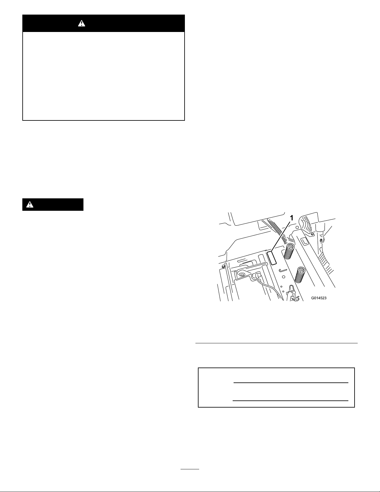
g014523
Figure1
Undertheseat
1.Modelandserialnumberplate
Writetheproductmodelandserialnumbersinthe
spacebelow:
ModelNo.
SerialNo.
Thismanualidentiespotentialhazardsandhas
safetymessagesidentiedbythesafetyalertsymbol
(Figure2),whichsignalsahazardthatmaycause
seriousinjuryordeathifyoudonotfollowthe
recommendedprecautions.
©2017—TheToro®Company
8111LyndaleAvenueSouth
Bloomington,MN55420
Contactusatwww.Toro.com.
2
PrintedintheUSA
AllRightsReserved
Page 3

Figure2
1.Safetyalertsymbol.
Thismanualuses2wordstohighlightinformation.
Importantcallsattentiontospecialmechanical
informationandNoteemphasizesgeneralinformation
worthyofspecialattention.
Contents
Safety.......................................................................4
SafeOperatingPractices....................................4
ToroRidingMowerSafety...................................6
SlopeIndicator...................................................7
SafetyandInstructionalDecals..........................8
ProductOverview...................................................13
Controls...........................................................13
Operation................................................................15
AddingFuel......................................................15
CheckingtheEngine-OilLevel..........................16
BreakinginaNewMachine..............................16
ThinkSafetyFirst..............................................16
StartingtheEngine...........................................18
OperatingtheBlades........................................18
StoppingtheEngine.........................................18
Driving..............................................................19
StoppingtheMachine.......................................21
AdjustingtheHeight-of-Cut...............................21
AdjustingtheAnti-ScalpRollers........................21
PositioningtheSeat..........................................22
AdjustingtheMotion-ControlLevers.................22
PushingtheMachinebyHand..........................23
GrassDeector................................................24
TransportingtheMachine.................................24
LoadingtheMachine........................................24
OperatingTips.................................................26
Maintenance...........................................................27
RecommendedMaintenanceSchedule(s)...........27
Pre-MaintenanceProcedures..............................28
RaisingtheSeat...............................................28
Lubrication..........................................................28
GreasingtheBearings......................................28
EngineMaintenance...........................................29
ServicingtheAirCleaner..................................29
ServicingtheEngineOil....................................30
ServicingtheSparkPlug...................................32
CleaningtheCoolingSystem............................33
FuelSystemMaintenance...................................34
ReplacingtheIn-LineFuelFilter.......................34
ElectricalSystemMaintenance...........................35
ChargingtheBattery.........................................35
ServicingtheFuses..........................................36
DriveSystemMaintenance..................................37
CheckingtheTirePressure...............................37
g000502
ReleasingtheElectricBrake.............................37
MowerMaintenance.............................................38
ServicingtheCuttingBlades.............................38
LevelingtheMowerDeck..................................40
RemovingtheMower........................................42
MowerBeltMaintenance..................................43
InstallingtheMower..........................................43
ReplacingtheGrassDeector..........................44
Cleaning..............................................................45
WashingtheUndersideoftheMower................45
Storage...................................................................46
CleaningandStorage.......................................46
Troubleshooting......................................................47
Schematics.............................................................49
3
Page 4

Safety
Toreducethepotentialforinjury,comply
withthesesafetyinstructionsandalwayspay
attentiontothesafetyalertsymbol,whichmeans
CAUTION,WARNING,orDANGER-"personal
safetyinstruction."Failuretocomplywiththe
instructionmayresultinpersonalinjuryordeath.
SafeOperatingPractices
Thisproductiscapableofamputatinghandsand
feetandthrowingobjects.Alwaysfollowallsafety
instructionstoavoidseriousinjuryordeath.
ThefollowinginstructionsareadaptedfromANSI
standardB71.1-2012.Allthelanguagewithinthis
ANSIstandardappliestothismachine;however,
duetotheapplicationofthestandardacrossmany
differenttypesofproductssomestatementscan
seemgeneralormisleading.Intheseinstances,T oro
hasrenedthestatementtoconveythemeaningof
thestandardwhilebettermatchingtheproductthis
Operator'sManualpertains.Safetyinformationin
additiontotheinstructionsfoundintheANSIstandard
belowcanbefoundinToroRidingMowerSafetyat
theendofthissection.
GeneralOperation
•Read,understand,andfollowallinstructionsin
theoperator'smanualandonthemachinebefore
starting.
•Donotplacehandsorfeetnearrotatingpartsor
underthemachine.Keepclearofthedischarge
openingatalltimes.
•Allowonlyresponsibleadultswhoarefamiliarwith
theinstructionstooperatethemachine.
•Cleartheareaofobjectssuchasrocks,toys,wire,
etc.,whichcouldbepickedupandthrownbythe
blade.
•Besuretheareaisclearofotherpeoplebefore
mowing.Stopthemachineifanyoneentersthe
area.
•Nevercarrypassengers.
•Donotmowinreverseunlessabsolutely
necessary.Alwayslookdownandbehindbefore
andwhilebackingup.
•Beawareofthemowerdischargedirectionanddo
notpointitatanyone.Avoiddischargingmaterial
againstawallorobstruction.Materialmayricochet
backtowardtheoperator.Stoptheblade(s)when
crossinggravelsurfaces.
•Donotoperatethemachinewithoutdeector,
dischargecoverorentiregrasscollectionsystem
inplaceandworking.
•Bealert,slowdownandusecautionwhenmaking
turns.Lookbehindandtothesidebeforechanging
directions.
•Neverleavearunningmachineunattended.
Alwaysturnoffblades,setparkingbrake,stop
engine,andremovekeybeforedismounting.
•Turnoffbladeswhennotmowing.Stoptheengine,
waitforallpartstocometoacompletestopand
removethekeybeforecleaningthemachine,
removingthegrasscatcheroruncloggingthe
dischargechute.
•Operatethemachineonlyindaylightorgood
articiallight.
•Donotoperatethemachinewhileunderthe
inuenceofalcoholordrugs.
•Watchfortrafcwhenoperatingnearorcrossing
roadways.
•Useextracarewhenloadingorunloadingthe
machineintoatrailerortruck.
•Alwaysweareyeprotectionwhenoperatingthe
mower.
•Dataindicatesthatoperators,age60yearsand
above,areinvolvedinalargepercentageofriding
mower-relatedinjuries.Operatorsshouldevaluate
theirabilitytooperatetheridingmowersafely
enoughtoprotectthemselvesandothersfrom
seriousinjury.
•Alwaysfollowtherecommendationsforany
applicationofcounterweights.
•Lightningcancausesevereinjuryordeath.If
lightningisseenorthunderisheardinthearea,do
notoperatethemachine;seekshelter.
SlopeOperation
Slopesareamajorfactorrelatedtolossofcontroland
tip-overaccidents,whichcanresultinsevereinjuryor
death.Operationonallslopesrequiresextracaution.
Ifyoucannotbackuptheslopeorifyoufeeluneasy
onit,donotmowit.
•Donotmowslopesgreaterthan15degrees.
•Watchforditches,holes,rocks,dips,andrises
thatchangetheoperatingangle,asroughterrain
couldoverturnthemachine.
•Choosealowgroundspeedsoyouwillnothave
tostopwhileoperatingonaslope.
•Donotmowslopeswhengrassiswet.Slippery
conditionsreducetractionandcouldcausesliding
andlossofcontrol.
•Alwayskeepthedrivewheelsengagedwhen
goingdownslopes.
•Reducespeedanduseextremecautiononslopes.
4
Page 5

•Donotmakesuddenturnsorrapidspeedchanges.
•Removeormarkobstaclessuchasrocks,tree
limbs,etc.fromthemowingarea.Tallgrasscan
hideobstacles.
•Avoidsuddenstartswhenmowinguphillbecause
themowermaytipbackwards.
•Beawarethatlossoftractionmayoccurgoing
downhill.Weighttransfertothefrontwheels
maycausedrivewheelstoslipandcauselossof
brakingandsteering.
•Alwaysavoidsuddenstartingorstoppingona
slope.Iftireslosetraction,stopthemachine,
disengagethebladesandproceedslowlyoffthe
slope.
•Useextremecarewithgrasscatchersorother
attachments.Thesecanchangethestabilityofthe
machineandcauselossofcontrol.
•Donottrytostabilizethemachinebyputtingyour
footontheground.
•Donotmowneardrop-offs,ditches,steepbanks
orwater.Wheelsdroppingoveredgescancause
rollovers,whichmayresultinseriousinjury,death
ordrowning.
•Useawalkbehindmowerand/orahandtrimmer
neardrop-offs,ditches,steepbanksorwater.
TowingSafety
•Donotattachtowedequipmentexceptatthehitch
point.
•Followtheattachmentmanufacturer's
recommendationforweightlimitsfortowed
equipmentandtowingonslopes.Towedweight
mustnotexceedtheweightofthemachine,
operator,andballast.Usecounterweightsor
wheelweightsasdescribedintheattachment,or
inthepullingmachineOperator’sManual.
•Neverallowchildrenorothersinorontowed
equipment.
•Onslopes,theweightofthetowedequipmentmay
causelossoftraction,increasedriskofrollover,
andlossofcontrol.Reducethetowedweightand
slowdown.
•Stoppingdistanceincreaseswiththeweightofthe
towedload.Travelslowlyandallowextradistance
tostop.
•Makewideturnstokeeptheattachmentclearof
themachine.
Service
SafeHandlingofGasoline:
Children
Tragicaccidentscanoccuriftheoperatorisnot
alerttothepresenceofchildren.Childrenareoften
attractedtothemachineandthemowingactivity.
Neverassumethatchildrenwillremainwhereyou
lastsawthem.
•Keepchildrenoutofthemowingareaandunder
thewatchfulcareofanotherresponsibleadult,not
theoperator.
•Bealertandturnthemachineoffifchildrenenter
thearea.
•Beforeandwhilebackingorchangingdirection,
lookbehind,down,andside-to-sideforsmall
children.
•Nevercarrychildren,evenwiththebladesoff.
Theymayfalloffandbeseriouslyinjuredor
interferewithsafemachineoperation.
•Childrenwhohavebeengivenridesinthepast
maysuddenlyappearinthemowingareafor
anotherrideandberunoverorbackedoverby
themower.
•Neverallowchildrentooperatethemachine.
•Useextracarewhenapproachingblindcorners,
shrubs,trees,theendofafenceorotherobjects
thatmayobscurevision.
Toavoidpersonalinjuryorpropertydamage,use
extracarewhenhandlinggasolineandotherfuels.
Theyareammableandthevaporsareexplosive.
•Extinguishallcigarettes,cigars,pipesandother
sourcesofignition.
•Useonlyanapprovedcontainer.
•Neverremovethegascaporaddfuelwhenthe
engineisrunning.Allowtheenginetocoolbefore
refueling.
•Neverrefuelthemachineindoors.
•Neverstorethemachineorfuelcontainerinside
wherethereisanopename,suchasneara
waterheaterorfurnace.
•Neverllcontainersinsideavehicleorona
truckortrailerwithaplasticliner.Alwaysplace
containersonthegroundawayfromyourvehicle
beforelling.
•Removegas-poweredequipmentfromthetruck
ortrailerandrefuelitontheground.Ifthisis
notpossible,thenrefuelsuchequipmentwitha
portablecontainer,ratherthanfromagasoline
dispensernozzle.
•Keepthenozzleincontactwiththerimofthefuel
tankorcontaineropeningatalltimesuntilthe
fuelingiscomplete.Donotuseanozzlelock-open
device.
5
Page 6

•Iffuelisspilledonclothing,changeclothing
immediately.
mustknowthatmaynotbeincludedintheANSI
standards.
•Neveroverllthefueltank.Replacegascapand
tightensecurely.
GeneralService:
•Neveroperateamachineinsideaclosedarea.
Engineexhaustcontainscarbonmonoxide,which
isanodorless,deadlypoisonthatcankillyou.
•Keepnutsandboltstight,especiallytheblade
attachmentbolts.Keepequipmentingood
condition.
•Neverinterferewiththeintendedfunctionofa
safetydeviceortoreducetheprotectionprovided
byasafetydevice.Checktheirproperoperation
regularly.
•Keepthemachinefreeofgrass,leaves,orother
debrisbuild-up.Cleanupoilorfuelspillagefuel
soakeddebris.Allowthemachinetocoolbefore
storing.
•Stopandinspecttheequipmentifyoustrikean
object.Repair,ifnecessary,beforerestarting.
•Nevermakeanyadjustmentsorrepairswiththe
enginerunning.
•Stoptheengine,movethemotion-controllevers
toneutralandoutwardtotheparkposition,
disengagetheblade-controlswitch,remove
keybeforeanddisconnectsparkplugwire(s)
performinganyservice,repairs,maintenanceor
adjustments.
•Keephands,feet,hair,andlooseclothingaway
fromattachmentdischargearea,undersideof
mowerandanymovingpartswhileengineis
running.
•Donottouchequipmentorattachmentpartswhich
maybehotfromoperation.Allowtocoolbefore
attemptingtomaintain,adjustorservice.
•Batteryacidispoisonousandcancauseburns.
Avoidcontactwithskin,eyes,andclothing.Protect
yourface,eyes,andclothingwhenworkingwitha
battery.
•Batterygasescanexplode.Keepcigarettes,
sparksandamesawayfrombattery .
•UseonlyToroapprovedattachments.Warranty
maybevoidedifusedwithunapproved
attachments.
•Grasscatchercomponentsaresubjecttowear,
damageanddeterioration,whichcouldexpose
movingpartsorallowobjectstobethrown.
Frequentlycheckcomponentsandreplace
withmanufacturers'recommendedparts,when
necessary.
•Mowerbladesaresharpandcancut.Wrapthe
blade(s)orwearthickly-paddedgloves,anduse
extracautionwhenservicingthem.
•Checkforproperbrakeoperationfrequently.
Adjustandserviceasrequired.
•Maintainorreplacesafetyandinstructiondecals
asnecessary.
•Removingstandardoriginalequipmentpartsand
accessoriesmayalterthewarranty,traction,and
safetyofthemachine.Failuretouseoriginal
Toropartscouldcauseseriousinjuryordeath.
Makingunauthorizedchangestotheengine,fuel
orventingsystem,mayviolateEPAandCARB
regulations.
•Replaceallpartsincluding,butnotlimitedto,tires,
belts,blades,andfuelsystemcomponentswith
originalToroparts.
•Ifloadingthemachineontoatrailerortruck,use
asingle,full-widthramponly.Therampangle
shouldnotexceed15degrees.
ToroRidingMowerSafety
Thefollowinglistcontainssafetyinformationspecic
toT oroproductsorothersafetyinformationthatyou
6
Page 7
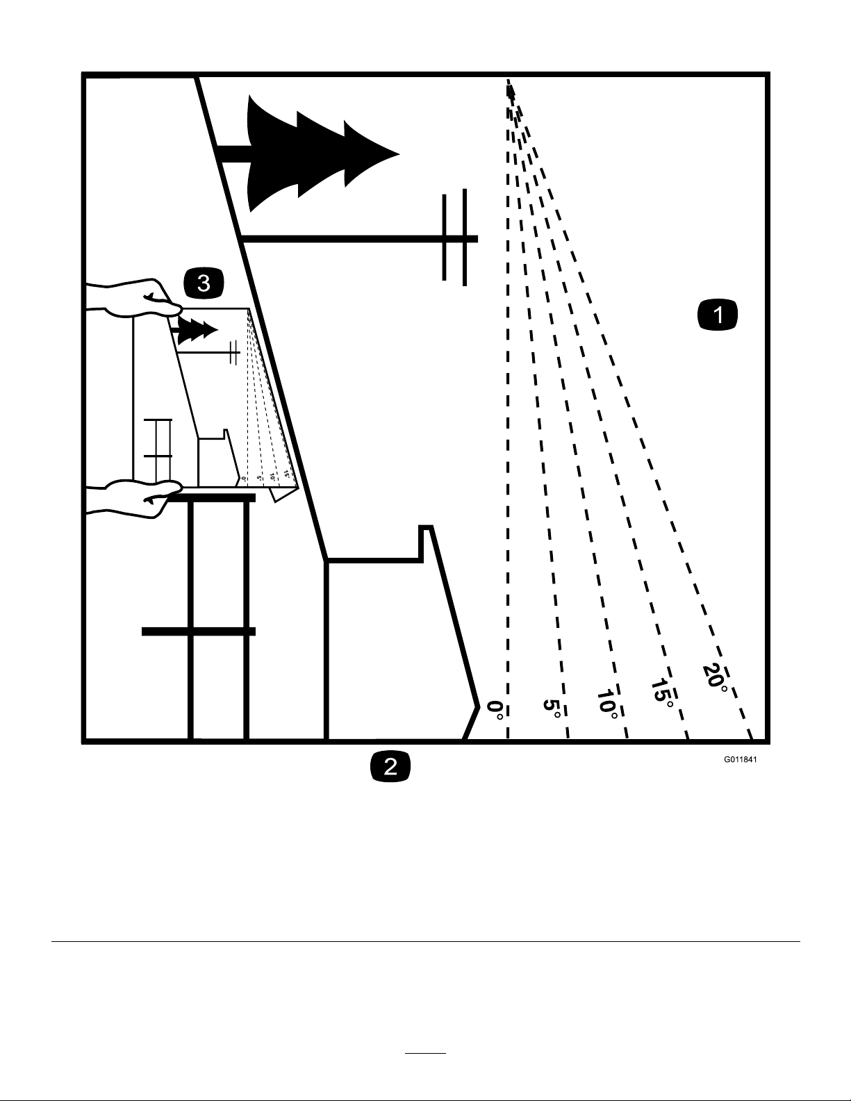
SlopeIndicator
Figure3
Thispagemaybecopiedforpersonaluse.
1.Themaximumslopeyoucansafelyoperatethemachineonis15degrees.Usetheslopecharttodeterminethedegreeofslope
ofhillsbeforeoperating.Donotoperatethismachineonaslopegreaterthan15degrees.Foldalongtheappropriateline
tomatchtherecommendedslope.
2.Alignthisedgewithaverticalsurface,atree,building,fencepole,etc.
3.Exampleofhowtocompareslopewithfoldededge.
7
g011841
Page 8
SafetyandInstructionalDecals
Safetydecalsandinstructionsareeasilyvisibletotheoperatorandarelocatednearanyarea
ofpotentialdanger.Replaceanydecalthatisdamagedorlost.
93-7009
1.Warning—don'toperatethemowerwiththedeectorupor
removed;keepthedeectorinplace.
2.Cutting/dismembermenthazardofhandorfoot,mower
blade—stayawayfrommovingparts.
decal93-7009
114-1606
1.Entanglementhazard,belt—keepallguardsinplace.
110-6691
1.Thrownobjecthazard—keepbystandersasafedistance
fromthemachine.
2.Thrownobjecthazard,mower—donotoperatewithoutthe
deector,dischargecover,orgrasscollectionsystemin
place.
3.Cutting/dismembermentofhandorfoot—stayawayfrom
movingparts.
decal114-1606
decal105-7015
105-7015
ForModelswith42InchDecks
decal106-8717
decal110-6691
1.Readtheinstructionsbeforeservicingorperforming
maintenance.
2.Checktirepressureevery25operatinghours.
3.Greaseevery25operatinghours.
4.Engine
106-8717
1.Parkingposition4.Neutral
2.Fast5.Reverse
3.Slow
8
decal119-8814
119-8814
Page 9
119-8815
1.Parkingposition4.Neutral
2.Fast5.Reverse
3.Slow
decal119-8815
decalbatterysymbols
BatterySymbols
Someorallofthesesymbolsareonyourbattery
1.Explosionhazard
2.Nore,opename,or
smoking.
3.Causticliquid/chemical
burnhazard
4.Weareyeprotection9.Flusheyesimmediately
5.ReadtheOperator's
Manual.
6.Keepbystandersasafe
distancefromthebattery.
7.Weareyeprotection;
explosivegasescan
causeblindnessandother
injuries
8.Batteryacidcancause
blindnessorsevereburns.
withwaterandgetmedical
helpfast.
10.Containslead;donot
discard.
decal119-8871
119-8871
Certainmodelsonly
decal121-2989b
121-2989
1.Height-of-cut
1.Bypassleverpositionfor
pushingthemachine
2.Bypassleverpositionfor
operatingthemachine
decaloemmarkt
Manufacturer'sMark
1.Indicatesthebladeisidentiedasapartfromtheoriginal
machinemanufacturer.
9
Page 10
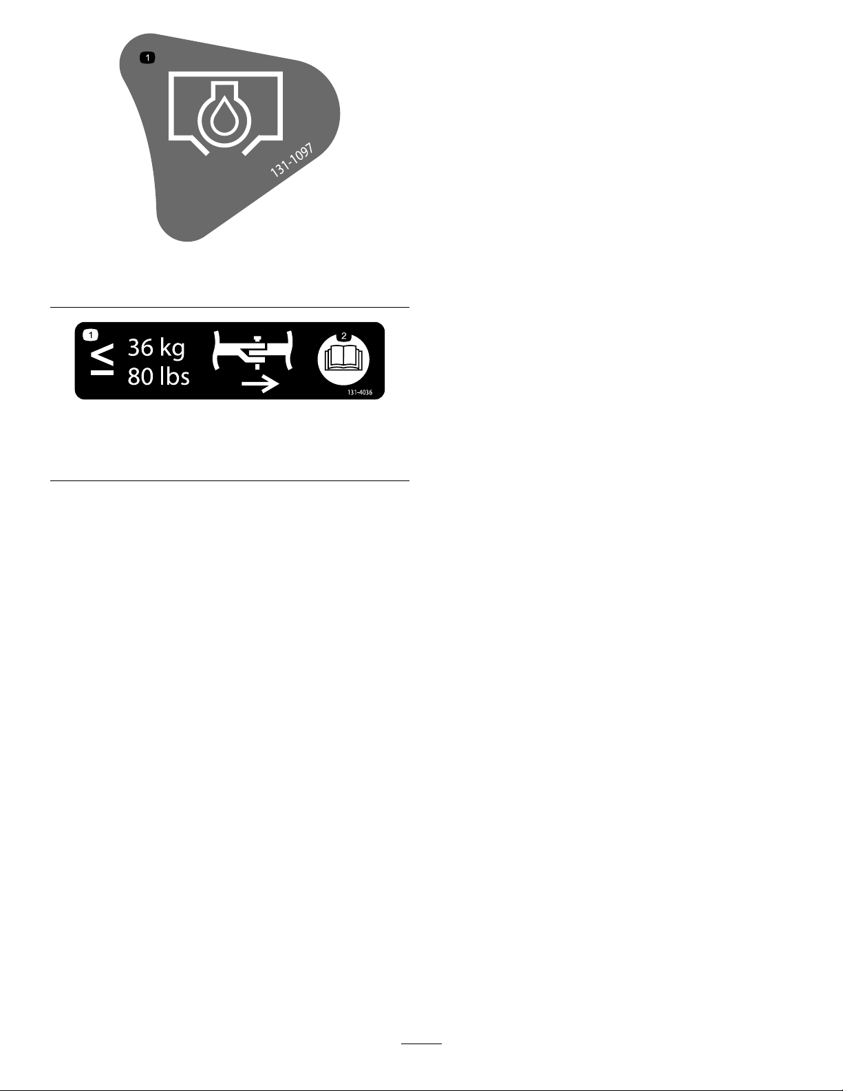
1.Oildrain
decal131-1097
131-1097
decal131-4036
131-4036
1.Maximumdrawbarpull36
kg(80lb)
2.ReadtheOperator's
Manual.
10
Page 11
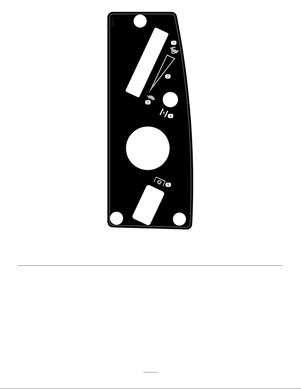
decal121-0772
121-0772
1.Fast
4.Choke
2.Continuousvariablesetting5.Powertake-off(PTO),Bladecontrolswitch
3.Slow
11
Page 12
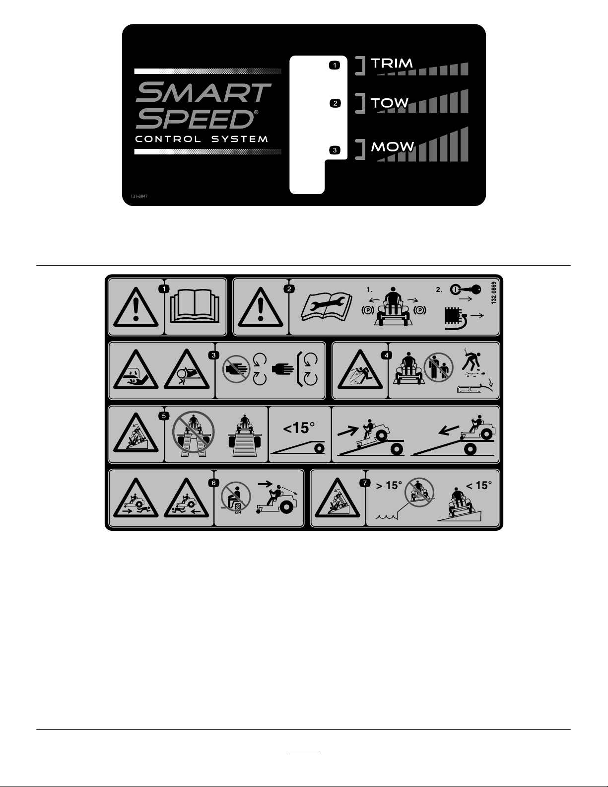
decal131-3947
131–3947
1.Trim—slow
3.Mow—fast
2.Tow—medium
1.Warning—readthe
Operator'sManual.
2.Warning—beforeservicing,
engagetheparkingbrake,
removethekeyandthe
sparkplugconnection.
3.Cuttinghazardofhand,
mowerblade;pinching
hazardofhand,belt—keep
handsandfeetawayfrom
movingparts;keepall
guardsandshieldsinplace.
4.Thrownobject
hazard—keepbystanders
awayfromthemachine;
removedebrisfromthe
areabeforemowing;keep
thedeectorshielddown.
decal132-0869
132-0869
5.Ramptipping
hazard—whenloading
ontoatrailer,donotuse
dualramps;onlyusea
singlerampwideenough
forthemachineandthat
hasaninclinelessthan
15degrees;backupthe
ramp(inreverse)anddrive
forwardofftheramp.
6.Bodilyharmhazard—no
riders;lookbehindyou
whenmowinginreverse.
7.Tippinghazardon
slopes—donotuseon
slopesnearopenwater;do
notuseonslopesgreater
than15degrees.
12
Page 13
ProductOverview
Figure4
1.Deector6.Operatorseat
2.Reardrivewheel
3.Controlpanel
4.Motion-controllevers9.Frontcasterwheel
5.Heightofcutlever
7.SmartSpeed™lever
8.Footrest
g028161
g027839
Figure5
ControlPanel
1.Throttle3.blade-controlswitch
2.Ignitionswitch
(powertake-off)
4.Choke
Controls
BecomefamiliarwithallofthecontrolsinFigure4
andFigure5beforeyoustarttheengineandoperate
themachine.
IgnitionSwitch
Theignitionswitchhasthreepositions,Off,Runand
Start.ThekeywillturntoStartandmovebacktoRun
uponrelease.TurningthekeytotheOffpositionwill
stoptheengine;however,alwaysremovethekey
whenleavingthemachinetopreventsomeonefrom
accidentallystartingtheengine(Figure5).
ThrottleControl
Thethrottlecontrolstheenginespeedandithasa
continuousvariablesettingfromSlowtoFast(Figure
5).
ChokeControl
PullupontheChokecontroluntilitstopstochokethe
engine(Figure5).PushdownontheChokecontrol
fornormalengineoperation
13
Page 14
Blade-ControlSwitch(Power
Take-off)
Theblade-controlswitch,representedbyapower
take-off(PTO)symbol,engagesanddisengages
powertothemowerblades(Figure5).
Motion-ControlLeversandPark
Position
Themotion-controlleversarespeedsensitivecontrols
ofindependentwheelmotors.Movingaleverforward
orbackwardturnsthewheelonthesamesideforward
orinreverse;wheelspeedisproportionaltothe
amounttheleverismoved.Movethecontrollevers
outwardfromthecentertotheparkpositionand
exitthemachine(Figure15).Alwayspositionthe
motion-controlleversintotheparkpositionwhenyou
stopthemachineorleaveitunattended.
SmartSpeed™ControlSystem
Lever
TheSmartSpeed™Control-Systemlever,located
belowtheoperatingposition,givestheoperatora
choicetodrivethemachineat3speedranges—trim,
tow,andmow(Figure6).
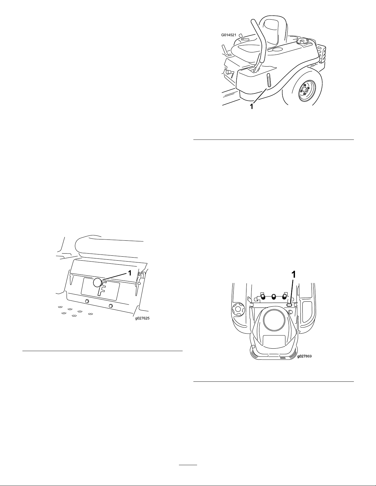
g014521
Figure7
1.Fuelpresencewindow
Height-of-CutLever
Theheightofcutleverallowstheoperatortolower
andraisethedeckfromtheseatedposition.When
theleverismovedup,towardtheoperatorthedeckis
raisedfromthegroundandwhenmoveddown,away
fromtheoperatoritisloweredtowardtheground.
Onlyadjusttheheightofcutwhilemachineisnot
moving(Figure19).
HourMeter
Figure6
1.Smart-speedlever
FuelWindow
Thefuelwindowlocatedonthelefthandsideof
themachinecanbeusedtoverifythepresenceof
gasolineinthetank(Figure7).
Thehourmeterrecordsthenumberofhourswhen
theoperatorisintheseatandtheignitionswitchisin
theONposition(Figure8).
g027625
g027869
Figure8
14
Page 15

Operation
Note:Determinetheleftandrightsidesofthe
machinefromthenormaloperatingposition.
AddingFuel
DANGER
Incertainconditions,gasolineisextremely
ammableandhighlyexplosive.Areor
explosionfromgasolinecanburnyouand
othersandcandamageproperty.
•Fillthefueltankoutdoors,inanopenarea,
whentheengineiscold.Wipeupany
gasolinethatspills.
•Neverllthefueltankinsideanenclosed
trailer.
•Donotllthefueltankcompletelyfull.
Addgasolinetothefueltankuntilthefuel
reachesthebaseofthellerneck.This
emptyspaceinthetankallowsgasoline
toexpand.
•Neversmokewhenhandlinggasoline,and
stayawayfromanopenameorwhere
gasolinefumesmaybeignitedbyaspark.
DANGER
Incertainconditionsduringfueling,static
electricitycanbereleasedcausingaspark
whichcanignitethegasolinevapors.Are
orexplosionfromgasolinecanburnyouand
othersandcandamageproperty.
•Alwaysplacegasolinecontainersonthe
groundawayfromyourvehiclebefore
lling.
•Donotllgasolinecontainersinsidea
vehicleoronatruckortrailerbedbecause
interiorcarpetsorplastictruckbedliners
mayinsulatethecontainerandslowthe
lossofanystaticcharge.
•Whenpractical,removegas-powered
equipmentfromthetruckortrailerand
refueltheequipmentwithitswheelsonthe
ground.
•Ifthisisnotpossible,thenrefuelsuch
equipmentonatruckortrailerfroma
portablecontainer,ratherthanfroma
gasolinedispensernozzle.
•Ifagasolinedispensernozzlemustbe
used,keepthenozzleincontactwiththe
rimofthefueltankorcontaineropeningat
alltimesuntilfuelingiscomplete.
•Storegasolineinanapprovedcontainer
andkeepitoutofthereachofchildren.
Neverbuymorethana30-daysupplyof
gasoline.
•Donotoperatewithoutentireexhaust
systeminplaceandinproperworking
condition.
WARNING
Gasolineisharmfulorfatalifswallowed.
Long-termexposuretovaporscancause
seriousinjuryandillness.
•Avoidprolongedbreathingofvapors.
•Keepfaceawayfromnozzleandgastank
orconditioneropening.
•Keepgasawayfromeyesandskin.
UsingStabilizer/Conditioner
Useafuelstabilizer/conditionerinthemachineto
providethefollowingbenets:
•Keepsgasolinefreshduringstorageof90daysor
less.Forlongerstorageitisrecommendedthat
thefueltankbedrained.
•Cleanstheenginewhileitruns
•Eliminatesgum-likevarnishbuildupinthefuel
system,whichcauseshardstarting
Important:Donotusefueladditives
containingmethanolorethanol.
Addthecorrectamountofgasstabilizer/conditioner
tothegas.
15
Page 16
Note:Afuelstabilizer/conditionerismosteffective
whenmixedwithfreshgasoline.T ominimizethe
chanceofvarnishdepositsinthefuelsystem,use
fuelstabilizeratalltimes.
new,placingadditionalloadontheengine.Allow
40to50hoursofbreak-intimefornewmachinesto
developfullpowerandbestperformance.
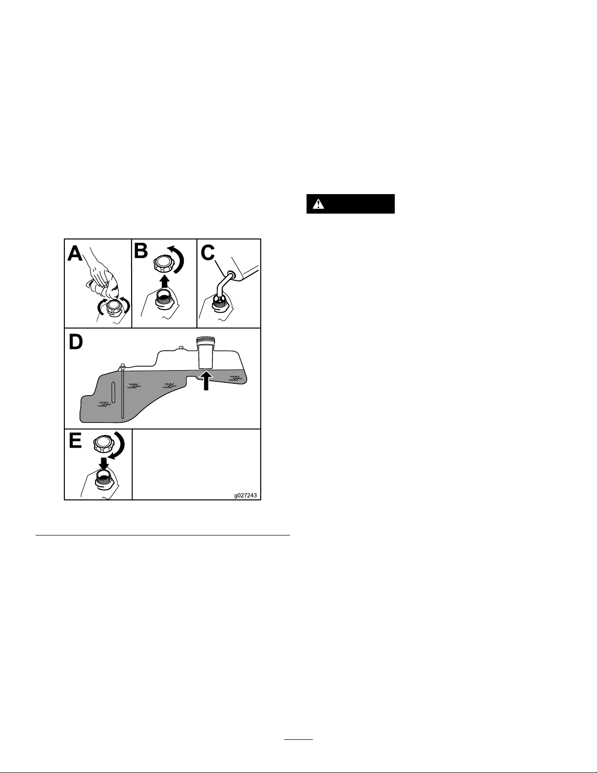
FillingtheFuelTank
Note:Ensurethattheengineisshutoffandthe
motioncontrolsareintheparkedposition.
Note:Y oucanusethefuelwindowtoverifythe
presenceofgasolinebeforellingthetank(Figure9).
Important:Donotoverllfueltank.Fillthefuel
tanktothebottomofthellerneck.Theempty
spaceinthetankallowsthefueltoexpand.
Overllingmayresultinfuelleakage,damageto
theengine,ordamagetotheemissionssystem.
ThinkSafetyFirst
OperatingSafety
Pleasecarefullyreadallofthesafetyinstructionsand
decalsinthesafetysection.Knowingthisinformation
couldhelpyou,yourfamily,petsorbystandersavoid
injury.
DANGER
Mowingonwetgrassorsteepslopescan
causeslidingandlossofcontrol.
Wheelsdroppingoveredgescancause
rollovers,whichmayresultinseriousinjury,
deathordrowning.
Alossoftractionisalossofsteeringcontrol.
Toavoidlossofcontrolandpossibilityof
rollover:
•Donotmowneardrop-offsornearwater.
•Donotmowslopesgreaterthan15degrees.
Figure9
CheckingtheEngine-Oil Level
Beforeyoustarttheengineandusethemachine,
checktheoillevelintheenginecrankcase;referto
CheckingtheOilLevelintheEngineMaintenance
section.
•Reducespeedanduseextremecautionon
slopes.
•Whenmowingslopes,graduallyworkfrom
lowertohigherareasontheincline.
•Avoidsuddenturnsorrapidspeed
changes.
•Turnup,intoaninclinewhenchanging
g027243
directionsonslopes.T urningdownthe
slopereducestraction.
•Attachmentschangethehandling
characteristicsofthemachine.Useextra
cautionwhenusingattachmentswiththe
machine.
BreakinginaNewMachine
Newenginestaketimetodevelopfullpower.Mower
decksanddrivesystemshavehigherfrictionwhen
16
Page 17

Figure10
1.SafeZone-usethe
TimeCutterhere
2.Usewalkbehindmower
and/orhandtrimmernear
drop-offsandwater.
3.Water
CAUTION
Thismachineproducessoundlevelsin
excessof85dBAattheoperatorsearandcan
causehearinglossthroughextendedperiods
ofexposure.
Wearhearingprotectionwhenoperatingthis
machine.
Theuseofprotectiveequipmentforeyes,ears,
hands,feet,andheadisrecommended.
Figure11
1.Wearsafetyglasses
2.Wearhearingprotection
Understandingthe
Safety-InterlockSystem
WARNING
Ifsafety-interlockswitchesaredisconnected
ordamagedthemachinecouldoperate
unexpectedlycausingpersonalinjury.
•Donottamperwiththeinterlockswitches.
•Checktheoperationoftheinterlock
switchesdailyandreplaceanydamaged
switchesbeforeoperatingthemachine.
Thesafety-interlocksystemisdesignedtopreventthe
g000513
enginefromstartingunless:
•Thebladesaredisengaged.
•Themotion-controlleversareintheparkposition.
Thesafety-interlocksystemalsoisdesignedtostop
theenginewheneverthecontrolleversareoutofthe
parkpositionandyourisefromtheseat.
TestingtheSafety-Interlock
System
Testthesafety-interlocksystembeforeyouusethe
machineeachtime.Ifthesafetysystemdoesnot
operateasdescribedbelow,haveanAuthorized
ServiceDealerrepairthesafetysystemimmediately .
1.Whilesittingontheseat,withthecontrollevers
inparkposition,andmovetheblade-control
switchtoOn.
2.Trystartingtheengine;theengineshouldnot
crank.
3.Whilesittingontheseat,movetheblade-control
switchtoOff.
4.Moveeithermotion-controllevertothecenter,
unlockedposition.
5.Trystartingtheengine;theengineshouldnot
g009027
crank.
6.Repeatwiththeothermotion-controllever.
7.Whilesittingontheseat,movetheblade-control
switchtoOff,andlockthemotion-controllevers
intheparkposition.
8.Starttheengine.
9.Whiletheengineisrunning,engagethe
blade-controlswitch,andriseslightlyfromthe
seat.
Note:Theengineshouldstop.
10.Whilesittingontheseat,movetheblade-control
switchtoOff,andlockthemotion-controllevers
intheparkposition.
11.Starttheengine.
17
Page 18

12.Whiletheengineisrunning,movethe
motion-controlleverstothecenter,unlocked
position,engagetheblade-controlswitch,and
riseslightlyfromtheseat.
Note:Theengineshouldstop.
StartingtheEngine
Note:Awarmorhotenginemaynotrequirechoking.
Important:Donotengagethestarterformore
than5secondsatatime.Engagingthestarter
motorformorethan5secondscandamagethe
startermotor.Iftheenginefailstostart,wait10
secondsbeforeoperatingtheenginestarteragain.
powertoanyattachmentsthatdrawpowerfromthe
engine,includingthemowerdeckandcuttingblades.
EngagingtheBlades
Important:Donotengagethebladeswhen
parkedintallgrass.Beltorclutchdamagecan
occur.
Note:Alwaysengagethebladeswiththethrottlein
theFastposition.
Figure12
g027582
Figure13
DisengagingtheBlades
g027581
1.Powertake-off(PTO)switch
Figure14
g027538
OperatingtheBlades
Theblade-controlswitch,representedbyapower
take-off(PTO)symbol,engagesanddisengages
powertothemowerblades.Thisswitchcontrols
StoppingtheEngine
1.Disengagethebladesbymovingthe
blade-controlswitchtoOff(Figure14).
18
Page 19

2.MovethethrottlelevertotheFastposition
(Figure13).
3.TurntheignitionkeytoOff(Figure5)and
removethekey.
Driving
Drivingthemachinebenetsfromanunderstanding
ofwhatzero-turn-radiusmowermeans.Thedrive
wheelsturnindependently,poweredbyhydraulic
motorsoneachaxle;henceonesidecanturnin
reversewhiletheotherturnsforwardcausingthe
machinetospinratherthanturn.Thisvastlyimproves
themachinemaneuverabilitybutmayrequiresome
adjustmentiftheoperatorisunfamiliar.
WARNING
Themachinecanspinveryrapidly.The
operatormaylosecontrolofthemachine
andcausepersonalinjuryordamagetothe
machine.
•Usecautionwhenmakingturns.
•Slowthemachinedownbeforemaking
sharpturns.
Thethrottlecontrolregulatestheenginespeedas
measuredinrpm(revolutionsperminute).Placing
thethrottlecontrolintheFastpositioncanbebestfor
performance.Formostapplications,operatinginthe
full-throttlepositionisdesirable.
Figure15
1.Park(brake)position
2.Center,unlockposition5.Frontofthemachine
3.Forward
19
g004532
4.Backward
Page 20

UsingtheSmartSpeed
TM
Control
System
TheSmartSpeed
belowtheoperatingposition(Figure16),givesthe
operatorachoicetodrivethemachineat3ground
speedranges—trim,tow,andmow.
1.Smartspeedlever
TM
Control-Systemlever,located
Figure16
Thisisthemediumspeed.Thesuggestedusesfor
thisspeedareasfollows:
•Bagging
•Mulching
Mow
Thisisthefastestspeed.Thesuggestedusesforthis
speedareasfollows:
•Normalmowing
•Transportingthemachine
DrivingForward
1.Movetheleverstothecenter,unlockedposition.
2.T ogoforward,slowlypushthemotion-control
leversforward(Figure17).
g027625
Tochangespeeds,dothefollowing:
1.Movethemotion-controlleverstoneutraland
outwardtotheparkposition.
2.Disengagetheblade-controlswitch
3.Adjustthelevertothedesiredposition.
Thefollowingareonlyrecommendationsforuse.
Adjustmentswillvarybygrasstype,moisturecontent,
andtheheightofthegrass.
Suggested
uses:
ParkingX
Heavy,wet
grass
TrainingX
BaggingX
MulchingX
Normal
mowing
Transport
TrimTowMow
X
Trim
g008952
Figure17
Togostraight,applyequalpressuretoboth
motion-controllevers(Figure17).
Toturn,releasepressureonthemotion-control
X
levertowardthedirectionyouwanttoturn
(Figure17).
X
Thefartheryoumovethemotion-controllevers
ineitherdirection,thefasterthemachinewill
moveinthatdirection.
Thisisthelowestspeed.Thesuggestedusesforthis
speedareasfollows:
•Parking
•Heavy,wetgrassmowingconditions
•Training
Tow
Tostop,pullthemotion-controlleverstoneutral.
20
Page 21

DrivingBackward
Note:Alwaysusecautionwhenbackingupand
turning.
1.Movetheleverstothecenter,unlockedposition.
AdjustingtheHeight-of-Cut
Note:Thetransportpositionisthehighest
height-of-cutpositionorcuttingheight(115mm(4.5
inches))asshowninFigure19.
2.T ogobackward,lookbehindyouanddown,
asyouslowlypullthemotion-controllevers
rearward(Figure18).
Figure18
Togostraight,applyequalpressuretoboth
motion-controllevers(Figure18).
Height-of-cutiscontrolledbytheleverlocatedtothe
rightoftheoperatingposition(Figure19).
g008953
Toturn,releasethepressureonthe
motion-controllevertowardthedirectionyou
wanttoturn.
Tostop,pushthemotion-controlleversto
neutral.
StoppingtheMachine
Tostopthemachine,movethemotion-controllevers
toneutralandoutwardtotheparkposition,disengage
theblade-controlswitch,ensurethethrottleisin
thefastposition,andturntheignitionkeytoOff.
Remembertoremovethekeyfromtheignitionswitch.
WARNING
Childrenorbystandersmaybeinjuredifthey
moveorattempttooperatethemowerwhile
itisunattended.
Alwaysremovetheignitionkeyandmove
themotion-controlleversoutwardtothe
parkpositionwhenleavingthemachine
unattended,evenifjustforafewminutes.
g028025
Figure19
AdjustingtheAnti-Scalp Rollers
Wheneveryouchangetheheight-of-cut,itis
recommendedtoadjusttheheightoftheanti-scalp
rollers.
Note:Adjusttheanti-scalprollerssotherollersdo
nottouchthegroundinnormal,atmowingareas.
1.Disengagetheblade-controlswitch(PTO),
movethemotion-controlleverstotheneutral
lockpositionandsettheparkingbrake.
2.Stoptheengine,removethekey,andwait
forallmovingpartstostopbeforeleavingthe
operatingposition.
21
Page 22

3.Adjusttheanti-scalprollerstooneofthe
followingpositions:
•Upperhole—usethispositionwiththemower
deckinthe63mm(2-1/2inch)andbelow
height-of-cutpositions(Figure20).
•Lowerhole—usethispositionwiththe
mowerdeckinthe76mm(3inch)andabove
height-of-cutpositions(Figure20).
Figure20
1.Anti-scalproller4.Upperhole—themower
2.Lowerhole—themower
deckinthe76mm(3inch)
andaboveheight-of-cut
positions
3.FlangeNut
deckinthe63mm
(2-1/2inch)andbelow
height-of-cutpositions
5.Bolt
g019929
g027249
Figure21
Adjustingthe Motion-ControlLevers
PositioningtheSeat
Theseatcanmoveforwardandbackward.Position
theseatwhereyouhavethebestcontrolofthe
machineandaremostcomfortable.
AdjustingtheHeight
Themotion-controlleverscanbeadjustedhigheror
lowerformaximumoperatorcomfort(Figure22).
g027252
Figure22
AdjustingtheTilt
Themotion-controlleverscanbetiltedforeoraftfor
maximumoperatorcomfort.
1.Loosentheupperboltholdingthecontrollever
tothecontrolarmshaft.
22
Page 23

2.Loosenthelowerboltjustenoughtopivotthe
controlleverforeoraft(Figure22).Tightenboth
boltstosecurethecontrolinthenewposition.
3.Repeattheadjustmentfortheoppositecontrol
lever.
PushingtheMachineby Hand
Important:Alwayspushthemachinebyhand.
Nevertowthemachinebecausedamagemay
occur.
Thismachinehasanelectricbrakemechanismandto
pushthemachinetheignitionkeyneedstobeinthe
Runposition.Thebatteryneedstobechargedand
functioningfortheelectricbraketobedisengage.
PushingtheMachine
1.Parkthemachineonalevelsurfaceand
disengagetheblade-controlswitch.
2.Movethemotion-controlleversoutwardtopark
position,stoptheengine,andwaitforallmoving
partstostopbeforeleavingtheoperating
position.
3.Locatethebypassleversontheframeonboth
sidesoftheengine.
4.Movethebypassleversforwardthroughthekey
holeanddowntolocktheminplaceasshownin
Figure23.Ensurethisisdoneforeachlever.
5.Movethemotion-controlleversinwardtothe
neutralpositionandturntheignitionkeytothe
runposition.Donotstartthemachine.
Themachineisnowabletobepushedbyhand.
g017303
Figure23
1.Bypassleverlocation
2.Leverpositionfor
operatingthemachine
6.Whennished,ensurethekeyhasbeen
returnedtotheStoppositiontoavoiddraining
thebatterycharge.
Ifthemachinefailstomovetheelectricbrakemaystill
beengaged.Ifnecessarytheelectricbrakecanbe
releasedmanually .RefertotheReleasingtheElectric
Brake(page37).
3.Leverpositionforpushing
themachine
OperatingtheMachine
Movethebypassleversrearwardthroughthekeyhole
anddowntolocktheminplaceasshowninFigure23.
Ensurethisisdoneforeachlever.
23
Page 24

GrassDeector
Themowerhasahingedgrassdeectorthat
dispersesclippingstothesideanddowntowardthe
turf.
DANGER
Withoutthegrassdeector,dischargecover,
orcompletegrasscatcherassemblymounted
inplace,youandothersareexposedtoblade
contactandthrowndebris.Contactwith
rotatingmowerblade(s)andthrowndebris
willcauseinjuryordeath.
•Neverremovethegrassdeectorfrom
themowerbecausethegrassdeector
routesmaterialdowntowardtheturf.Ifthe
grassdeectoriseverdamaged,replaceit
immediately.
•Neverputyourhandsorfeetunderthe
mower.
•Nevertrytocleardischargeareaormower
bladesunlessyoumovetheblade-control
switchtoOffandrotatetheignitionkeyto
Off.Alsoremovethekeyandpullthewire
offthesparkplug(s).
TransportingtheMachine
Useaheavy-dutytrailerortrucktotransportthe
machine.Ensurethatthetrailerortruckhasall
necessarybrakes,lighting,andmarkingasrequired
bylaw.Pleasecarefullyreadallthesafetyinstructions.
Knowingthisinformationcouldhelpyou,yourfamily,
pets,orbystandersavoidinjury.
WARNING
Drivingonthestreetorroadwaywithoutturn
signals,lights,reectivemarkings,oraslow
movingvehicleemblemisdangerousandcan
leadtoaccidentscausingpersonalinjury.
Donotdrivemachineonapublicstreetor
roadway.
Figure24
LoadingtheMachine
Useextremecautionwhenloadingorunloading
machinesontoatraileroratruck.Useafull-width
rampthatiswiderthanthemachineforthisprocedure.
Backuprampsanddriveforwarddownramps(Figure
25).
Figure25
1.Backupramps
Important:Donotusenarrowindividualramps
foreachsideofthemachine.
Ensuretherampislongenoughsothattheanglewith
thegrounddoesnotexceed15degrees(Figure26).
Onatground,thisrequiresaramptobeatleastfour
times(4X)aslongastheheightofthetrailerortruck
bedtotheground.Asteeperanglemaycausemower
componentstogetcaughtastheunitmovesfromthe
ramptothetrailerortruck.Steeperanglesmayalso
causethemachinetotiporlosecontrol.Ifloadingon
ornearaslope,positionthetrailerortrucksothatitis
onthedownsideoftheslopeandtherampextends
uptheslope.Thiswillminimizetherampangle.
2.Driveforwarddownramps
g027708
g027995
Totransportthemachine:
1.Ifusingatrailer,connectittothetowingvehicle
andconnectthesafetychains.
2.Ifapplicable,connectthetrailerbrakes.
3.Loadthemachineontothetrailerortruck.
4.Stoptheengine,removethekey,setthebrake,
andclosethefuelvalve.
5.Tiedownthemachinenearthefrontcaster
wheelsandtherearbumper(Figure24).
24
Page 25

WARNING
Loadingamachineontoatrailerortruck
increasesthepossibilityoftip-overandcould
causeseriousinjuryordeath.
•Useextremecautionwhenoperatinga
machineonaramp.
•Useonlyafull-widthramp;donotuse
individualrampsforeachsideofthe
machine.
•Donotexceeda15-degreeanglebetween
therampandthegroundorbetweenthe
rampandthetrailerortruck.
•Ensurethelengthoframpisatleastfour
times(4X)aslongastheheightofthe
trailerortruckbedtotheground.Thiswill
ensurethatrampangledoesnotexceed15
degreesonatground.
•Backuprampsanddriveforwarddown
ramps.
•Avoidsuddenaccelerationordeceleration
whiledrivingthemachineonarampas
thiscouldcausealossofcontrolora
tip-oversituation.
g027996
Figure26
1.Full-widthrampinstowed
position
2.Sideviewoffull-width
rampinloadingposition
3.Notgreaterthan
15degrees
4.Rampisatleastfourtimes
(4X)aslongastheheight
ofthetrailerortruckbed
totheground
5.H=heightofthetraileror
truckbedtotheground
6.Trailer
25
Page 26

OperatingTips
FastThrottleSetting
Forbestmowingandmaximumaircirculation,operate
theengineattheFastposition.Airisrequiredto
thoroughlycutgrassclippings,sodonotsetthe
height-of-cutsolowastototallysurroundthemower
byuncutgrass.Alwaystrytohaveonesideofthe
mowerfreefromuncutgrass,whichallowsairtobe
drawnintothemower.
UsingtheSmartSpeed™Control
AvoidCuttingTooLow
Ifthecuttingwidthofthemoweriswiderthanthe
moweryoupreviouslyused,raisethecuttingheightto
ensurethatuneventurfisnotcuttooshort.
LongGrass
Ifthegrassiseverallowedtogrowslightlylongerthan
normal,orifitcontainsahighdegreeofmoisture,
raisethecuttingheighthigherthanusualandcutthe
grassatthissetting.Thencutthegrassagainusing
thelower,normalsetting.
System
TheSmartSpeed™ControlSystemlever,located
belowtheoperatingposition,givestheoperatora
choicetodrivethemachineat3speedranges—high,
tow,andlow.Anoperatorcanbenetfromthelower
speedsettingwhenmaneuveringthemachineintight
spacesoroperatingarounddelicatelandscapes.The
lowsettingcanalsobeusedtooperatethemachineat
ahighthrottlesettingandbladespeedwhilestillbeing
abletoreducegroundspeedtoincreasequalityofcut.
CuttingaLawnfortheFirstTime
Cutgrassslightlylongerthannormaltoensurethat
thecuttingheightofthemowerdoesnotscalpany
unevenground.However,thecuttingheightusedin
thepastisgenerallythebestonetouse.Whencutting
grasslongerthansixinchestall,youmaywanttocut
thelawntwicetoensureanacceptablequalityofcut.
Cut1/3oftheGrassBlade
Itisbesttocutonlyabout1/3ofthegrassblade.
Cuttingmorethanthatisnotrecommendedunless
grassissparse,oritislatefallwhengrassgrows
moreslowly.
MowingDirection
WhenStopping
Ifthemachine'sforwardmotionmustbestoppedwhile
mowing,aclumpofgrassclippingsmaydroponto
yourlawn.Toavoidthis,moveontoapreviouslycut
areawiththebladesengagedoryoucandisengage
themowerdeckwhilemovingforward.
KeeptheUndersideoftheMower
Clean
Cleanclippingsanddirtfromtheundersideofthe
moweraftereachuse.Ifgrassanddirtbuildupinside
themower,cuttingqualitywilleventuallybecome
unsatisfactory.
BladeMaintenance
Maintainasharpbladethroughoutthecuttingseason
becauseasharpbladecutscleanlywithouttearingor
shreddingthegrassblades.Tearingandshredding
turnsgrassbrownattheedges,whichslowsgrowth
andincreasesthechanceofdisease.Checkthe
cutterbladesdailyforsharpness,andforanywearor
damage.Filedownanynicksandsharpentheblades
asnecessary.Ifabladeisdamagedorworn,replace
itimmediatelywithagenuineT ororeplacementblade.
Alternatemowingdirectiontokeepthegrassstanding
straight.Thisalsohelpsdisperseclippingswhich
enhancesdecompositionandfertilization.
MowatCorrectIntervals
Normally,moweveryfourdays.Butremember,
grassgrowsatdifferentratesatdifferenttimes.So
tomaintainthesamecuttingheight,whichisagood
practice,mowmoreofteninearlyspring.Asthe
grassgrowthrateslowsinmidsummer,mowless
frequently.Ifyoucannotmowforanextendedperiod,
rstmowatahighcuttingheight;thenmowagaintwo
dayslateratalowerheightsetting.
26
Page 27

Maintenance
Note:Determinetheleftandrightsidesofthemachinefromthenormaloperatingposition.
RecommendedMaintenanceSchedule(s)
MaintenanceService
Interval
Aftertherst5hours
Beforeeachuseordaily
Aftereachuse
Every25hours
Every100hours
Every200hours
Beforestorage
MaintenanceProcedure
•Changetheengineoil.
•Checkthesafety-interlocksystem.
•Checktheengine-oillevel.
•Cleantheair-intakescreen.
•Checkthecuttingblades.
•Inspectthegrassdeectorfordamage
•Cleanthemowerdeckhousing.
•Greasealllubricationpoints.
•Cleanthefoamelement(moreoftenindusty,dirtyconditions).
•Checktirepressure.
•Checkthebeltsforwear/cracks.
•Replacethefoamelement(moreoftenindusty ,dirtyconditions).
•Servicethepaperelement(moreoftenindusty ,dirtyconditions).
•Changetheengineoil(moreoftenindusty,dirtyconditions).
•Changetheoillter(moreoftenindusty,dirtyconditions).
•Checkthesparkplug(s).
•Replacethepaperelement(moreoftenindusty ,dirtyconditions).
•Replacethesparkplug(s).
•Replacethein-linefuellter
•Chargethebatteryanddisconnectbatterycables.
•Performallmaintenanceprocedureslistedabovebeforestorage.
•Paintanychippedsurfaces.
CAUTION
Ifyouleavethekeyintheignitionswitch,someonecouldaccidentlystarttheengineand
seriouslyinjureyouorotherbystanders.
Removethekeyfromtheignitionanddisconnectthewirefromthesparkplugbeforeyoudo
anymaintenance.Setthewireasidesothatitdoesnotaccidentallycontactthesparkplug.
27
Page 28

Pre-Maintenance
Lubrication
Procedures
GreasingtheBearings
RaisingtheSeat
Makesurethemotion-controlleversarelockedinthe
parkposition.Lifttheseatforward.
Thefollowingcomponentscanbeaccessedbyraising
theseat:
•Serialplate
•Servicedecal
•Seatadjustmentbolts
•Fuellter
•Batteryandbatterycables
ServiceInterval:Every25hours—Greaseall
lubricationpoints.
GreaseType:No.2GeneralPurposeLithiumBase
Grease
1.Parkthemachineonalevelsurfaceand
disengagetheblade-controlswitch.
2.Movethemotion-controlleversoutwardtothe
parkposition,stoptheengine,removethekey,
andwaitforallmovingpartstostopbefore
leavingtheoperatingposition.
3.Cleanthegreasettings(Figure27andFigure
28)witharag.Makesuretoscrapeanypaintoff
ofthefrontofthetting(s).
Figure27
1.Frontcastertire
Figure28
Locatedontheseatpanunderside
1.Readtheinstructions
beforeservicingor
performingmaintenance.
2.Checktirepressureevery
25operatinghours.
4.Connectagreaseguntoeachtting(Figure27
andFigure28).Pumpgreaseintothettings
untilgreasebeginstooozeoutofthebearings.
3.Greaseevery25operating
hours.
4.Engine
g014522
decal106-8717
28
Page 29

5.Wipeupanyexcessgrease.
EngineMaintenance
ServicingtheAirCleaner
Note:Servicetheaircleanermorefrequently(every
fewhours)ifoperatingconditionsareextremelydusty
orsandy.
RemovingtheElements
1.Parkthemachineonalevelsurfaceand
disengagetheblade-controlswitch(PTO).
2.Engagetheparkingbrake,stoptheengine,
removethekey,andwaitforallmovingpartsto
stopbeforeleavingtheoperatingposition.
3.Cleanaroundtheair-cleanercovertoprevent
dirtfromgettingintotheengineandcausing
damage.
4.Liftthecoverandrotatetheair-cleanerassembly
outoftheengine(Figure29).
Figure29
5.Removethefoamelementfromthepaper
element(Figure30).
g027800
g027801
29
Page 30

Figure30
ServicingtheFoamElement
ServiceInterval:Every25hours/Monthly(whichever
comesrst)—Cleanthefoam
element(moreoftenindusty,dirty
conditions).
Every100hours/Y early(whichevercomes
rst)—Replacethefoamelement(moreoftenin
dusty,dirtyconditions).
ServicingtheEngineOil
OilType:Detergentoil(APIserviceSF,SG,SH,SJ,
orSL)
CrankcaseCapacity:2.4L(2.5USqt)
Viscosity:Seethetablebelow.
g027802
g027924
Figure31
Washthefoamelementwithwaterandreplacethe
foamelementifitisdamaged.
ServicingthePaperElement
ServiceInterval:Every100hours/Yearly(whichever
comesrst)—Servicethepaper
element(moreoftenindusty,dirty
conditions).
Every200hours/Every2years(whichever
comesrst)—Replacethepaperelement(more
oftenindusty ,dirtyconditions).
1.Lightlytaptheelementonaatsurfaceto
removedustanddirt.
2.Inspecttheelementfortears,anoilylm,and
damagetotheseal.
Important:Donotcleanthepaperelement
withpressurizedairorliquids,suchas
solvent,gas,orkerosene.Replacethepaper
elementifitisdamagedorcannotbecleaned
thoroughly.
CheckingtheEngine-oilLevel
ServiceInterval:Beforeeachuseordaily
Note:Checktheoilwhentheengineiscold.
WARNING
Contactwithhotsurfacesmaycausepersonal
injury.
Keephands,feet,face,clothing,andother
bodypartsawaythemuferandotherhot
surfaces.
Important:Donotoverllthecrankcasewithoil,
becausedamagetotheenginemayresult.Donot
runenginewithoilbelowtheLowmark,because
theenginemaybedamaged.
1.Parkthemachineonalevelsurface,disengage
theblade-controlswitch,stoptheengine,
engageparkingbrake,andremovethekey.
2.Makesuretheengineisstopped,level,andis
cool,sotheoilhashadtimetodrainintothe
sump.
3.T okeepdirt,grassclippings,etc.,outofthe
engine,cleantheareaaroundtheoil-llcapand
dipstickbeforeremovingit(Figure32).
4.Stoptheengine,removethekey,andwait
forallmovingpartstostopbeforeleavingthe
operatingposition.
30
Page 31

Figure32
g027799
g027475
ChangingtheEngineOil
ServiceInterval:Aftertherst5hours/Afterthe
rstmonth(whichevercomes
rst)—Changetheengineoil.
Every100hours/Y early(whichevercomes
rst)—Changetheengineoil(moreoftenin
dusty,dirtyconditions).
Note:Disposeoftheusedoilatarecyclingcenter.
1.Parkthemachinesothatthedrainsideisslightly
lowerthantheoppositesidetoassuretheoil
drainscompletely.
2.DisengagethePTOandensuretheparking
brakeisengaged.
3.Stoptheengine,removethekey,andwait
forallmovingpartstostopbeforeleavingthe
operatingposition.
g027823
Figure33
31
Page 32

4.Slowlypourapproximately80%ofthespecied
oilintothellertubeandslowlyaddthe
additionaloiltobringittotheFullmark(Figure
34).
ChangingtheEngine-OilFilter
ServiceInterval:Every100hours/Yearly(whichever
comesrst)—Changetheoil
lter(moreoftenindusty,dirty
conditions).
Note:Changetheengine-oilltermorefrequently
whenoperatingconditionsareextremelydustyor
sandy.
1.Draintheoilfromtheengine;refertoChanging
theEngineOil(page31).
2.Changetheengineoillter(Figure36).
Figure34
5.InstallthedrainhoseasshowninFigure35.
g027484
g027477
Figure36
Note:Ensurethattheoil-ltergaskettouches
theengineandthenanextra3/4turnis
completed.
3.Fillthecrankcasewiththepropertypeofnew
oil;refertoServicingtheEngineOil(page30).
Figure35
ServicingtheSparkPlug
ServiceInterval:Every100hours/Yearly(whichever
g027825
Every200hours/Every2years(whichever
comesrst)—Replacethesparkplug(s).
32
comesrst)—Checkthespark
plug(s).
Page 33

Makesuretheairgapbetweenthecenterandside
electrodesiscorrectbeforeinstallingthesparkplug.
Useaspark-plugwrenchforremovingandinstalling
thesparkplug(s)andagappingtool/feelergaugeto
checkandadjusttheairgap.Installanewspark
plug(s)ifnecessary.
Type:ChampionRN9YC
Airgap:0.76mm(0.03inch)
RemovingtheSparkPlug
1.DisengagethePTOandensuretheparking
brakeisengaged.
2.Stoptheengine,removethekey,andwait
forallmovingpartstostopbeforeleavingthe
operatingposition.
InstallingtheSparkPlug
Tightenthesparkplug(s)to25–30N-m(18.5–22.1
ft-lb).
g027960
Figure39
Figure37
Note:Duetothedeeprecessaroundthespark
plug,blowingoutthecavitywithcompressedair
isusuallythemosteffectivemethodforcleaning.
Thesparkplugismostaccessiblewhenthe
blowerhousingisremovedforcleaning.
CheckingtheSparkPlug
Important:Donotcleanthesparkplug(s).
Alwaysreplacethesparkplug(s)whenithas:a
blackcoating,wornelectrodes,anoilylm,or
cracks.
Ifyouseelightbrownorgrayontheinsulator,the
engineisoperatingproperly.Ablackcoatingonthe
insulatorusuallymeanstheaircleanerisdirty .
Setthegapto0.76mm(0.030inch).
g027478
CleaningtheCooling System
Cleantheair-intakescreenfromgrassanddebris
beforeeachuse.
1.Disengagetheblade-controlswitchandensure
theparkingbrakeisengaged.
2.Stoptheengine,removethekey,andwait
forallmovingpartstostopbeforeleavingthe
operatingposition.
3.Removetheair-intakescreen,theair-cleaner
cover,andthefanhousing.
4.Cleandebrisandgrassfromtheparts.
5.Installtheair-intakescreen,air-cleanercover,
andthefanhousing.
Figure38
g027479
33
Page 34

FuelSystem
Maintenance
DANGER
Incertainconditions,gasolineisextremely
ammableandhighlyexplosive.Areor
explosionfromgasolinecanburnyouand
othersandcandamageproperty.
•Performanyfuelrelatedmaintenance
whentheengineiscold.Dothisoutdoors
inanopenarea.Wipeupanygasolinethat
spills.
•Neversmokewhendraininggasoline,and
stayawayfromanopenameorwherea
sparkmayignitethegasolinefumes.
ReplacingtheIn-LineFuel Filter
g027939
ServiceInterval:Every200hours—Replacethe
in-linefuellter
Neverinstalladirtylterifitisremovedfromthefuel
line.
1.Parkthemachineonalevelsurfaceand
disengagetheblade-controlswitch.
2.Movethemotion-controlleversoutwardtothe
parkposition,stoptheengine,removethekey,
andwaitforallmovingpartstostopbefore
leavingtheoperatingposition.
g027753
Figure40
34
Page 35

ElectricalSystem
Maintenance
4.Disconnectthenegative(black)groundcable
fromthebatterypost(Figure41).Retainall
fasteners.
WARNING
CALIFORNIA
Proposition65Warning
Batteryposts,terminals,andrelated
accessoriescontainleadandlead
compounds,chemicalsknownto
theStateofCaliforniatocause
cancerandreproductiveharm.Wash
handsafterhandling.
ChargingtheBattery
WARNING
CALIFORNIA
Proposition65Warning
Batteryposts,terminals,andrelated
accessoriescontainleadandlead
compounds,chemicalsknownto
theStateofCaliforniatocause
cancerandreproductiveharm.Wash
handsafterhandling.
WARNING
Incorrectbatterycableroutingcould
damagethemachineandcablescausing
sparks.Sparkscancausethebattery
gassestoexplode,resultinginpersonal
injury.
•Alwaysdisconnectthenegative
(black)batterycablebefore
disconnectingthepositive(red)
cable.
•Alwaysconnectthepositive(red)
batterycablebeforeconnectingthe
negative(black)cable.
5.Slidetherubbercoverupthepositive(red)
cable.Disconnectthepositive(red)cablefrom
thebatterypost(Figure41).Retainallfasteners.
6.Removethebatteryhold-down(Figure41)and
liftthebatteryfromthebatterytray.
RemovingtheBattery
WARNING
Batteryterminalsormetaltoolscouldshort
againstmetalmachinecomponentscausing
sparks.Sparkscancausethebatterygasses
toexplode,resultinginpersonalinjury.
•Whenremovingorinstallingthebattery,
donotallowthebatteryterminalstotouch
anymetalpartsofthemachine.
•Donotallowmetaltoolstoshortbetween
thebatteryterminalsandmetalpartsofthe
machine.
1.Parkthemachineonalevelsurfaceand
disengagetheblade-controlswitch.
2.Movethemotion-controlleversoutwardtothe
parkposition,stoptheengine,removethekey,
andwaitforallmovingpartstostopbefore
leavingtheoperatingposition.
3.Raisetheseattoaccessthebattery.
g005072
Figure41
1.Battery5.Negativebatterypost
2.Positivebatterypost6.Wingnut,washer,andbolt
3.Bolt,washer,andnut7.Batteryhold-down
4.Terminalboot
ChargingtheBattery
ServiceInterval:Beforestorage—Chargethebattery
anddisconnectbatterycables.
1.Removethebatteryfromthechassis;referto
RemovingtheBattery.
35
Page 36

2.Chargethebatteryforaminimumof1hourat6
to10amps.Donotoverchargethebattery.
3.Whenthebatteryisfullycharged,unplug
thechargerfromtheelectricaloutlet,then
disconnectthechargerleadsfromthebattery
posts(Figure42).
g014921
Figure43
Figure42
1.Positivebatterypost
2.Negativebatterypost
3.Red(+)chargerlead
4.Black(-)chargerlead
InstallingtheBattery
1.Positionthebatteryinthetray(Figure41).
2.Installthepositive(red)batterycabletothe
positive(+)batteryterminalusingthefasteners
removedpreviously.
3.Installthenegativebatterycabletothenegative
(-)batteryterminalusingthefastenersremoved
previously.
4.Slidetheredterminalbootontothepositive
(red)batterypost.
5.Securethebatterywiththehold-down(Figure
41).
6.Lowertheseat.
1.Main-30amp
g000538
2.Chargecircuit-25amp
4.Returnthecontrolpaneltoitsoriginalposition.
Usethescrewsremovedpreviouslytosecure
thepaneltothemachine.
ServicingtheFuses
Theelectricalsystemisprotectedbyfuses.Itrequires
nomaintenance;however,ifafuseblows,checkthe
component/circuitforamalfunctionorshort.
Fuse:
•MainF1-30amp,blade-type
•ChargeCircuitF2-25amp,blade-type
1.Removethescrewssecuringthecontrolpanel
tothemachine.Retainallfasteners
2.Liftthecontrolpaneuptoaccessthemainwiring
harnessandfuseblock(Figure43).
3.T oreplaceafuse,pulloutonthefusetoremove
it(Figure43).
36
Page 37

DriveSystem
Maintenance
CheckingtheTirePressure
ServiceInterval:Every25hours—Checktire
pressure.
Maintaintheairpressureinthefrontandreartiresas
specied.Uneventirepressurecancauseuneven
cut.Checkthepressureatthevalvestem(Figure44).
Checkthetireswhentheyarecoldtogetthemost
accuratepressurereading.
Refertothemaximumpressuresuggestedbythetire
manufactureronthesidewallofthecasterwheeltires.
Inatethereardrivewheeltiresto89.6kPa(13psi).
g027911
Figure45
1.Rotatebrake-linkarmforwardontheelectric-brake-control
module
2.Leftreartire
Figure44
1.Valvestem
ReleasingtheElectric Brake
Theelectricbrakereleasesbymanuallyrotating
thelinkarmsforward.Oncetheelectricbrakeis
energizedthebrakewillreset.
Toreleasethebrake:
1.TurntheignitionkeytotheOffpositionor
disconnectthebattery.
2.Locatetheshaftswherethebrake-linkarmsare
connectedonbothsidesoftheelectricbrake
(Figure45).
3.Rotatetheshaftsforwardtoreleasethebrakes.
g000554
37
Page 38

MowerMaintenance
ServicingtheCutting Blades
Maintainsharpbladesthroughoutthecuttingseason,
becausesharpbladescutcleanlywithouttearingor
shreddingthegrassblades.Tearingandshredding
turnsgrassbrownattheedges,whichslowsgrowth,
andincreasesthechanceofdisease.
Checkthecutterbladesdailyforsharpness,and
foranywearordamage.Filedownanynicksand
sharpenthebladesasnecessary.Ifabladeis
damagedorworn,replaceitimmediatelywitha
genuineTororeplacementblade.Forconvenient
sharpeningandreplacement,youmaywanttokeep
extrabladesonhand.
Figure46
1.Cuttingedge3.Wear/slotforming
2.Curvedarea
4.Damage
CheckingforBentBlades
Note:Themachinemustbeonalevelsurfacefor
thefollowingprocedure.
g006530
WARNING
Awornordamagedbladecanbreak,anda
pieceofthebladecouldbethrownintothe
operator'sorbystander'sarea,resultingin
seriouspersonalinjuryordeath.
•Inspectthebladeperiodicallyforwearor
damage.
•Replaceawornordamagedblade.
BeforeInspectingorServicingthe
Blades
Parkthemachineonalevelsurface,disengagethe
blade-controlswitch,movethemotion-controllevers
outwardtotheparkposition,stoptheengine,and
removethekey.
InspectingtheBlades
ServiceInterval:Beforeeachuseordaily—Check
thecuttingblades.
1.Raisethemowerdecktothehighest
height-of-cutposition;alsoconsideredthe
'transport'position.
2.Whilewearingthicklypaddedgloves,orother
adequatehandprotection,slowlyrotatethe
bladetobemeasureintoapositionthatallows
effectivemeasurementofthedistancebetween
thecuttingedgeandthelevelsurfacethe
machineison(Figure47).
g014972
Figure47
1.Deck3.Blade
2.Spindlehousing
1.Inspectthecuttingedges(Figure46).
Note:Iftheedgesarenotsharporhave
nicks,removeandsharpentheblades;referto
SharpeningtheBlades(page40).
2.Inspecttheblades,especiallythecurvedarea
(Figure46).
Note:Ifyounoticeanydamage,wear,oraslot
forminginthisarea(items3and4inFigure46),
immediatelyinstallanewblade.
38
Page 39

3.Measurefromthetipofthebladetotheat
surface(Figure48).
g014973
Figure50
Figure48
1.Blade(inpositionformeasuring)
2.Levelsurface
3.Measureddistancebetweenbladeandthesurface(A)
4.Rotatethesameblade180degrees,sothat
theopposingcuttingedgeisnowinthesame
position(Figure49).
Figure49
1.Blade(sidepreviouslymeasured)
2.Measurement(positionusedpreviously)
3.Opposingsideofbladebeingmovedintomeasurement
position
5.Measurefromthetipofthebladetotheat
surface(Figure50).
Note:Thevarianceshouldbenomorethan
3mm(1/8inch).
g014973
1.Oppositebladeedge(inpositionformeasuring)
2.Levelsurface
3.Secondmeasureddistancebetweenbladeandsurface(B)
A.IfthedifferencebetweenAandBisgreater
than3mm(1/8inch),replacethebladewith
anewblade;refertoRemovingtheBlades
(page39)andInstallingtheBlades(page
40).
Note:Ifabentbladeisreplacedwithanew
one,andthedimensionobtainedcontinues
toexceed3mm(1/8inch),thebladespindle
couldbebent.ContactanAuthorizedToro
Dealerforservice.
B.Ifthevarianceiswithinconstraints,moveto
thenextblade.
Repeatthisprocedureoneachblade.
g014974
RemovingtheBlades
Thebladesmustbereplacedifasolidobjectishit,if
thebladeisoutofbalance,orifthebladeisbent.T o
ensureoptimumperformanceandcontinuedsafety
conformanceofthemachine,usegenuineT oro
replacementblades.Replacementbladesmadeby
othermanufacturersmayresultinnon-conformance
withsafetystandards.
1.Holdthebladeendusingaragorthickly-padded
glove.
2.Removethebladebolt,thecurvedwasher,and
thebladefromthespindleshaft(Figure51).
39
Page 40

Figure51
InstallingtheBlades
1.Installthebladeontothespindleshaft(Figure
51).
Important:Thecurvedpartoftheblade
mustbepointingupwardtowardtheinside
ofthemowertoensurepropercutting.
2.Installthethecurvedwasher(cuppedside
towardtheblade)andthebladebolt(Figure51).
3.T orquethebladeboltto47to88N-m(35to
65ft-lb).
g027833
LevelingtheMowerDeck
1.Sailareaoftheblade3.Curvedwasher
2.Blade4.Bladebolt
SharpeningtheBlades
1.Usealetosharpenthecuttingedgeatboth
endsoftheblade(Figure52).
Note:Maintaintheoriginalangle.
Note:Thebladeretainsitsbalanceifthesame
amountofmaterialisremovedfrombothcutting
edges.
Figure52
1.Sharpenatoriginalangle
2.Checkthebalanceofthebladebyputtingitona
bladebalancer(Figure53).
Note:Ifthebladestaysinahorizontalposition,
thebladeisbalanced,andcanbeused.
Checktoensurethemowerdeckislevelanytimeyou
installthemowerorwhenyouseeanunevencuton
yourlawn.
Themowerdeckmustbecheckedforbentblades
priortoleveling;anybentbladesmustberemoved
andreplaced.RefertotheCheckingforBentBlades
procedurebeforecontinuing.
Themowerdeckmustbeleveledside-to-siderst
thenthefronttorearslopecanbeadjusted.
Requirements:
•Themachinemustbeonalevelsurface.
•Allfourtiremustbeproperlyinated.Referto
CheckingtheTirePressureintheDriveSystem
Maintenancesection.
g000552
LevelingSide-to-Side
1.Parkthemachineonalevelsurfaceand
disengagetheblade-controlswitch.
2.Movethemotion-controlleversoutwardtothe
parkposition,stoptheengine,removethekey,
andwaitforallmovingpartstostopbefore
leavingtheoperatingposition.
3.Settheheight-of-cutlevertomiddleposition.
Note:Ifthebladeisnotbalanced,lesome
metalofftheendofthesailareaonly(Figure52).
Figure53
1.Blade2.Balancer
3.Repeatthisprocedureuntilthebladeis
balanced.
4.Carefullyrotatethebladessothattheyareall
sidetoside(Figure54).
g000553
40
Page 41

Figure54
1.Bladessidetoside
2.Sailareaofblade4.Measurefromthetipofthe
3.Outsidecuttingedges
bladetotheatsurface
here
5.Measurebetweentheoutsidecuttingedges
andtheatsurface(Figure54).Ifboth
measurementsarenotwithin3/16inch(5mm),
anadjustmentisrequired;continuewiththis
procedure.
6.Movetotheleftsideofthemachine.
7.Loosenthesidelockingnut.
8.Raiseorlowertheleftsideofthemowerdeck
byrotatingtherearnut.(Figure55).
9.Checktheside-to-sideadjustmentsagain.
Repeatthisprocedureuntilthemeasurements
arecorrect.
10.Continuelevelingthedeckbycheckingthe
front-to-rearbladeslope;refertoAdjustingthe
Front-to-RearBladeSlope(page41).
AdjustingtheFront-to-RearBlade
Slope
Checkthefront-to-rearbladelevelanytimeyouinstall
g009682
themower.Ifthefrontofthemowerismorethan
5/16inch(7.9mm)lowerthantherearofthemower,
adjustthebladelevelusingthefollowinginstructions:
1.Parkthemachineonalevelsurfaceand
disengagetheblade-controlswitch.
2.Movethemotion-controlleversoutwardtothe
parkposition,stoptheengine,removethekey,
andwaitforallmovingpartstostopbefore
leavingtheoperatingposition.
3.Settheheight-of-cutlevertomiddleposition.
Note:Checkandadjusttheside-to-sideblade
levelifyouhavenotcheckedthesetting;referto
Side-to-SideLeveling.
4.Carefullyrotatethebladessotheyarefacing
fronttorear(Figure56).
Note:Rotatetherearnutclockwiseto
raisethemowerdeck;rotatetherearnut
counter-clockwisetolowerthemowerdeck.
Figure55
1.Hangerbracket3.Rearlockingnut
2.Sidelockingnut
g009658
Figure56
1.Bladesfronttorear
2.Measurefromthetipofthebladetotheatsurfacehere
5.Measurefromthetipofthefrontbladetotheat
surfaceandthetipoftherearbladetotheat
surface(Figure56).Ifthefrontbladetipisnot
1/16-5/16inch(1.6-7.9mm)lowerthantherear
bladetip,adjustthefrontlocknut.
g027588
6.T oadjustthefront-to-rearbladeslope,rotatethe
adjustmentnutinthefrontofthemower(Figure
57).
41
Page 42

Figure57
1.Adjustingrod3.Locknut
2.Adjustingblock
7.T oraisethefrontofthemower,tightenthe
adjustmentnut.T olowerthefrontofthemower,
loosentheadjustmentnut.
8.Afteradjustment,checkthefront-to-rearslope
again.Continueadjustingthenutuntilthefront
bladetipis1/16-5/16inch(1.6-7.9mm)lower
thantherearbladetip(Figure56).
9.Whenthefront-to-rearbladeslopeiscorrect
checktheside-to-sidelevelofthemoweragain;
refertoLevelingSide-to-Side(page40).
RemovingtheMower
1.Parkthemachineonalevelsurfaceand
disengagetheblade-controlswitch.
2.Movethemotion-controlleversoutwardtothe
parkposition,stoptheengine,removethekey,
andwaitforallmovingpartstostopbefore
leavingtheoperatingposition.
g014634
g014635
Figure58
1.Frontsupportrod3.Deckbracket
2.Lockingnut
5.Liftthemowerdeckandhangerbracketsclear
oftherearliftrodandlowerthemowercarefully
totheground(Figure59).
3.Lowertheheight-of-cutlevertothelowest
position.
4.Removethehairpincotterfromthefrontsupport
rodandremovetherodfromthedeckbracket
(Figure58).Carefullylowerthefrontofthe
mowerdecktotheground.
Figure59
1.Mowerdeck
2.Hangerbracket
3.Rearliftrod
6.Slidethemowerdeckrearwardtoremovethe
mowerbeltfromtheenginepulley.
7.Slidethemowerdeckoutfromunderneaththe
machine.
Note:Retainallpartsforfutureinstallation.
42
g005077
Page 43

MowerBeltMaintenance
InspectingtheBelts
ServiceInterval:Every25hours—Checkthebelts
forwear/cracks.
Checkthebeltsforcracks,frayededges,burnmarks,
oranyotherdamage.Replacedamagedbelts.
ReplacingtheMowerBelt
Squealingwhenthebeltisrotating,bladesslipping
whencuttinggrass,frayedbeltedges,burnmarks,
andcracksaresignsofawornmowerbelt.Replace
themowerbeltifanyoftheseconditionsareevident.
1.Parkthemachineonalevelsurfaceand
disengagetheblade-controlswitch.
2.Movethemotion-controlleversoutwardtothe
parkposition,stoptheengine,removethekey,
andwaitforallmovingpartstostopbefore
leavingtheoperatingposition.
3.Settheheight-of-cutatthelowestcutting
position[1-1/2inch(38mm)].
Figure60
1.Idlerpulley
2.Mowerbelt5.Enginepulley
3.Outsidepulley6.Springremovaltoo
4.Spring
g014930
4.Usingaspringremovaltool,(T oropartno.
92-5771),removetheidlerspringfromthedeck
hooktoremovetensionontheidlerpulleyand
rollthebeltoffofthepulleys(Figure60).
WARNING
Thespringisundertensionwhen
installedandcancausepersonalinjury .
Becarefulwhenremovingthebelt.
5.Routethenewbeltaroundtheenginepulleyand
mowerpulleys(Figure60).
6.Usingaspringremovaltool,(T oropartno.
92-5771),installtheidlerspringoverthedeck
hookandplacingtensionontheidlerpulleyand
mowerbelt(Figure60).
InstallingtheMower
1.Parkthemachineonalevelsurfaceand
disengagetheblade-controlswitch.
2.Movethemotion-controlleversoutwardtothe
parkposition,stoptheengine,removethekey,
andwaitforallmovingpartstostopbefore
leavingtheoperatingposition.
3.Slidethemowerunderthemachine.
4.Lowertheheight-of-cutlevertothelowest
position.
5.Lifttherearofthemowerdeckandguidethe
hangerbracketsovertherearliftrod(Figure59).
6.Attachthefrontsupportrodtothemowerdeck
withtheclevispinandhairpincotter(Figure58).
7.Installthemowerbeltontotheenginepulley;
refertoReplacingtheMowerBelt.
43
Page 44

ReplacingtheGrass
Deector
ServiceInterval:Beforeeachuseordaily—Inspect
thegrassdeectorfordamage
WARNING
Anuncovereddischargeopeningcould
allowthelawnmowertothrowobjectsinthe
operator'sorbystander'sdirectionandresult
inseriousinjury.Also,contactwiththeblade
couldoccur.
Neveroperatethemachinewithoutgrass
deector,dischargecoverorgrasscollection
systeminplace.
Inspectthegrassdeectorfordamagebeforeeach
use.Replaceanydamagedpartsbeforeuse.
1.LocateitemsshowninFigure61.
Sliderodthroughsecondgrassdeectorbracket
(Figure61).
7.Insertrodatfrontofgrassdeectorintoshort
stand-offondeck.Securerearendofrodinto
themowerwithanut(3/8inch)(Figure61).
Important:Thegrassdeectormustbe
springloadedinthedownposition.Liftthe
deectoruptotestthatitsnapstothefull
downposition.
Figure61
1.Mowerdeck
2.Grassdeector6.Nut(3/8inch)
3.Grassdeectorbracket7.Shortstand-off
4.Rod
2.Removethenut(3/8inch)fromtherodunder
themower(Figure61).
3.Slidetherodoutoftheshortstand-off,spring,
andgrassdeector(Figure61).Removethe
damagedorworngrassdeector.
4.Replacethegrassdeector(Figure61).
5.Sliderod,straightend,throughthereargrass
deectorbracket.
6.Placethespringontherod,withendwires
down,andbetweenthegrassdeectorbrackets.
5.Spring
g005192
44
Page 45

Cleaning
6.Disengagetheblade-controlswitch,stopthe
engine,andremovetheignitionkey.Waitforall
movingpartstostop.
WashingtheUndersideof theMower
ServiceInterval:Aftereachuse—Cleanthemower
deckhousing.
Washtheundersideofthemoweraftereachuseto
preventgrassbuildupforimprovedmulchactionand
clippingdispersal.
Important:Youcanwashthemachinewithmild
detergentandwater.Donotpressurewashthe
machine.Avoidexcessiveuseofwater,especially
nearthecontrolpanel,undertheseat,aroundthe
engine,hydraulicpumps,andmotors.
1.Parkthemachineonalevelsurfaceand
disengagetheblade-controlswitch.
2.Movethemotion-controlleversoutwardtothe
parkposition,stoptheengine,removethekey,
andwaitforallmovingpartstostopbefore
leavingtheoperatingposition.
3.Attachthehosecouplingtotheendofthe
mowerwashouttting,andturnthewateron
high(Figure62).
7.Turnthewateroffandremovethecouplingfrom
thewashouttting.
Note:Ifthemowerisnotcleanafterone
washing,soakitandletitstandfor30minutes.
Thenrepeattheprocess.
8.Runthemoweragainforonetothreeminutesto
removeexcesswater.
WARNING
Abrokenormissingwashouttting
couldexposeyouandotherstothrown
objectsorbladecontact.Contactwith
bladeorthrowndebriscancauseinjury
ordeath.
•Replacebrokenormissingwashout
ttingimmediately,beforeusing
moweragain.
•Neverputyourhandsorfeetunder
themowerorthroughopeningsinthe
mower.
Note:Spreadpetroleumjellyonthewashout
ttingO-ringtomakethecouplingslideon
easierandprotecttheO-ring.
Figure62
1.Washouttting3.O-ring
2.Hose
4.Coupling
g003934
4.Lowerthemowertothelowestheight-of-cut.
5.Sitontheseatandstarttheengine.Engagethe
blade-controlswitchandletthemowerrunfor
onetothreeminutes.
45
Page 46

Storage
CleaningandStorage
1.Disengagetheblade-controlswitch,movethe
motioncontrolsoutwardtotheparkposition,
stoptheengine,andremovethekey.
2.Removegrassclippings,dirt,andgrimefromthe
externalpartsoftheentiremachine,especially
theengine.Cleandirtandchafffromtheoutside
oftheenginecylinderheadnsandblower
housing.
Important:Youcanwashthemachinewith
milddetergentandwater.Donotpressure
washthemachine.Avoidexcessiveuse
ofwater,especiallynearthecontrolpanel,
undertheseat,aroundtheengine,hydraulic
pumps,andmotors.
3.Servicetheaircleaner;refertoServicingtheAir
Cleaner(page29).
4.Greaseandoilthemachine;refertoLubrication
(page28).
cylinder.Installthesparkplug(s).Donotinstall
thewireonthesparkplug(s).
12.Cleananydirtandchafffromthetopofthe
mower.
13.Scrapeanyheavybuildupofgrassanddirt
fromtheundersideofthemower,thenwashthe
mowerwithagardenhose.
14.Checktheconditionofthedriveandmower
belts.
15.Checkandtightenallbolts,nuts,andscrews.
Repairorreplaceanypartthatiswornor
damaged.
16.Paintallscratchedorbaremetalsurfaces.Paint
isavailablefromyourAuthorizedServiceDealer.
17.Storethemachineinaclean,drygarageor
storagearea.Removethekeyfromtheignition
switchandkeepitinamemorableplace.Cover
themachinetoprotectitandkeepitclean.
5.Changethecrankcaseoilandlter;referto
ServicingtheEngineOil(page30).
6.Checkthetirepressure;refertoCheckingthe
TirePressure(page37).
7.Chargethebattery;refertoChargingtheBattery
(page35).
8.Checktheconditionoftheblades;referto
ServicingtheCuttingBlades(page38).
9.Preparethemachineforstoragewhennon-use
occursover30days.Preparethemachinefor
storageasfollows.
10.Addapetroleumbasedstabilizer/conditioner
tothefuelinthetank.Followthemixing
instructionsfromthestabilizermanufacturer.Do
notuseanalcoholbasedstabilizer(ethanolor
methanol).
Note:Afuelstabilizer/conditionerismost
effectivewhenmixedwithfreshgasolineand
usedatalltimes.
Runtheenginetodistributetheconditionedfuel
throughthefuelsystem(5minutes).
Important:Donotstore
stabilizer/conditionedgasolineover90days.
11.Removethesparkplug(s)andcheckits
condition;refertoServicingtheSparkPlug
(page32).Withthesparkplug(s)removedfrom
theengine,pourtwotablespoonsofengine
oilintothesparkplughole.Usethestarterto
cranktheengineanddistributetheoilinsidethe
46
Page 47

Troubleshooting
Problem
Thefueltankisshowingsignsof
collapsingorthemachineisshowingsigns
offrequentlyrunningoutoffuel.
Theengineoverheats.
Thestarterdoesnotcrank.
Theenginedoesnotstart,startshard,or
failstokeeprunning.
PossibleCauseCorrectiveAction
1.Theaircleanerpaperelementclogged.
1.Theengineloadisexcessive.1.Reducegroundspeed.
2.Theoillevelinthecrankcaseislow.2.Addoiltothecrankcase.
3.Thecoolingnsandairpassages
undertheengineblowerhousingare
plugged.
4.Theaircleanerisdirty.
5.Dirt,water,orstalefuelisinfuel
system.
1.Theblade-controlswitchisengaged.1.Movetheblade-controlswitchto
2.Themotion-controlleversarenotin
theparkposition.
3.Thebatteryisdead.
4.Theelectricalconnectionsare
corrodedorloose.
5.Afuseisblown.5.Replacethefuse.
6.Arelayorswitchisdamaged.
1.Thefueltankisempty.1.Fillthefueltank.
2.Thechokeisnoton.
3.Theaircleanerisdirty.
4.Thesparkplugwire(s)islooseor
disconnected.
5.Thesparkplug(s)ispitted,fouled,or
thegapisincorrect.
6.Thereisdirtinfuellter.6.Replacethefuellter.
7.Dirt,water,orstalefuelisinfuel
system.
8.Thereisincorrectfuelinthefueltank.
9.Theoillevelinthecrankcaseislow.9.Addoiltothecrankcase.
1.Cleanthepaperelement.
3.Removetheobstructionfromthe
coolingnsandairpassages.
4.Cleanorreplacetheaircleaner
element.
5.ContactanAuthorizedServiceDealer
Disengaged.
2.Movethemotion-controllevers
outwardtotheparkposition.
3.Chargethebattery.
4.Checktheelectricalconnectionsfor
goodcontact.
6.ContactanAuthorizedServiceDealer.
2.MovethechokelevertoOn.
3.Cleanorreplacetheaircleaner
element.
4.Installthewire(s)onthesparkplug.
5.Installanew,correctlygappedspark
plug(s).
7.ContactanAuthorizedServiceDealer.
8.Drainthetankandreplacethefuelwith
thepropertype.
Theenginelosespower.
1.Theengineloadisexcessive.1.Reducegroundspeed.
2.Theaircleanerisdirty.
3.Theoillevelinthecrankcaseislow.3.Addoiltothecrankcase.
4.Thecoolingnsandairpassages
undertheengineblowerhousingare
plugged.
5.Thesparkplug(s)ispitted,fouled,or
thegapisincorrect.
6.Thefueltankventisblocked.6.ContactanAuthorizedServiceDealer.
7.Thereisdirtinthefuellter.7.Replacethefuellter.
8.Dirt,water,orstalefuelisinthefuel
system.
9.
Thereisincorrectfuelinthefueltank.
2.Cleantheaircleanerelement.
4.Removetheobstructionfromthe
coolingnsandairpassages.
5.Installanew,correctlygappedspark
plug(s).
8.
ContactanAuthorizedServiceDealer.
9.Drainthetankandreplacethefuelwith
thepropertype.
47
Page 48

Problem
PossibleCauseCorrectiveAction
Themachinedoesnotdrive.
Thereisabnormalvibration.
Thecuttingheightisuneven.
Thebladesdonotrotate.
1.Thebypassvalvesareopen.
2.Thetractionbeltsareworn,loose,or
broken.
3.Thetractionbeltsareoffofthepulleys.3.ContactanAuthorizedServiceDealer.
4.Thetransmissionhasfailed.4.ContactanAuthorizedServiceDealer.
1.Theenginemountingboltsareloose.1.Tightentheenginemountingbolts.
2.Theenginepulley ,idlerpulley,orblade
pulleyisloose.
3.Theenginepulleyisdamaged.
4.Thecuttingblade(s)is/arebentor
unbalanced.
5.Ablademountingboltisloose.5.Tightentheblademountingbolt.
6.Abladespindleisbent.
1.Theblade(s)isnotsharp.1.Sharpentheblade(s).
2.Acuttingblade(s)is/arebent.2.Installanewcuttingblade(s).
3.Themowerisnotlevel.
4.Ananti-scalpwheelisnotsetcorrectly.4.Adjusttheanti-scalpwheelheight.
5.Theundersideofthemowerisdirty.5.Cleantheundersideofthemower.
6.Thetirepressureisincorrect.6.Adjustthetirepressure.
7.Abladespindleisbent.
1.Thedrivebeltisworn,looseorbroken.1.Installanewdrivebelt.
2.Thedrivebeltisoffofthepulley .
3.ThePowerTake-Off(PTO)switchor
PTOclutchisfaulty.
4.Themowerbeltisworn,loose,or
broken.
1.Closethetowvalves.
2.ContactanAuthorizedServiceDealer.
2.Tightentheappropriatepulley.
3.ContactanAuthorizedServiceDealer.
4.Installanewcuttingblade(s).
6.ContactanAuthorizedServiceDealer.
3.Levelthemowerfromside-to-sideand
front-to-rear.
7.ContactanAuthorizedServiceDealer.
2.Installthedrivebeltandcheckthe
adjustingshaftsandbeltguidesforthe
correctposition.
3.ContactanAuthorizedServiceDealer.
4.Installanewmowerbelt.
48
Page 49

Schematics
ElectricalDiagram(Rev .A)
49
g028022
Page 50

Notes:
Page 51

Notes:
Page 52

TheT oroTotalCoverageWarranty
LimitedWarranty(seewarrantyperiodsbelow)
TimeCutter
and
TITAN
Mowers
ConditionsandProductsCovered
TheT oroCompanyanditsafliate,T oroWarrantyCompany ,pursuanttoan
agreementbetweenthem,jointlypromisetotheoriginalpurchasertorepair
theT oroProductslistedbelowifdefectiveinmaterialsorworkmanship.
Thefollowingtimeperiodsapplyfromthedateofpurchasebytheoriginal
owner:
ProductsWarrantyPeriod
TimeCutterandMXMowers
•Engines
1
Residentialuse
—ResidentialuseKawasaki–3years
2
–3years
Kohler–3years
Toro–3years
TimeCutterandMXMowersCommercialuse30days
•Engines
1
—Commercialuse
Kawasaki–3years
Kohler–90days
Toro–90days
TITANMowers–Residentialor
Commercialuse
•Engines
1
—Residentialor
Commercialuse
•Frame
TITANMX5400andMX600Mowers
–ResidentialorCommercialuse
•Engines
1
—Residentialor
Commercialuse
•Frame
3yearsor300hours
Kawasaki–3years
Lifetime(originalowneronly)
4yearsor400hours
Kawasaki–3years
Lifetime(originalowneronly)
3
4
3
4
AllMowers
•Attachments1year
•Battery90daysPartsandLabor
1yearPartsonly
•BeltsandTires90days
1
SomeenginesusedonT oroProductsarewarrantedbytheenginemanufacturer .
2
Residentialusemeansuseoftheproductonthesamelotasyourhome.Useatmorethanone
locationisconsideredcommercialuseandthecommercialusewarrantywouldapply .
3
Whicheveroccursrst.
4
LifetimeFrameWarranty-Ifthemainframe,consistingofthepartsweldedtogethertoformthe
tractorstructurethatothercomponentssuchastheenginearesecuredto,cracksorbreaksin
normaluse,itwillberepairedorreplaced,atT oro'soption,underwarrantyatnocostforpartsand
labor.Framefailureduetomisuseorabuseandfailureorrepairrequiredduetorustorcorrosion
arenotcovered.
Warrantymaybedeniedifthehourmeterisdisconnected,altered,or
showssignsofbeingtamperedwith.
OwnerResponsibilities
YoumustmaintainyourToroProductbyfollowingthemaintenance
proceduresdescribedintheOperator'sManual.Suchroutinemaintenance,
whetherperformedbyadealerorbyyou,isatyourexpense.
InstructionsforObtainingWarrantyService
IfyouthinkthatyourT oroProductcontainsadefectinmaterialsor
workmanship,followthisprocedure:
1.ContactanyAuthorizedT oroServiceDealertoarrangeserviceattheir
dealership.T olocateadealerconvenienttoyou,refertotheYellow
Pagesofyourtelephonedirectory(lookunder“LawnMowers”)or
accessourwebsiteatwww.T oro.com.Youmayalsocallthenumbers
listedinitem#3tousethe24-hourT oroDealerlocatorsystem.
2.Bringtheproductandyourproofofpurchase(salesreceipt)tothe
ServiceDealer.Thedealerwilldiagnosetheproblemanddetermineif
itiscoveredunderwarranty.
3.IfforanyreasonyouaredissatisedwiththeServiceDealer’s
analysisorwiththeassistanceprovided,contactusat:
CustomerCareDepartment,RLCDivision
ToroWarrantyCompany
811 1LyndaleAvenueSouth
Bloomington,MN55420-1196
Tollfreeat866-216-6029(U.S.customers)
Tollfreeat866-216-6030(Canadiancustomers)
ItemsandConditionsNotCovered
Thereisnootherexpresswarrantyexceptforspecialemissionsystem
coverageandenginewarrantycoverageonsomeproducts.Thisexpress
warrantydoesnotcoverthefollowing:
•Costofregularmaintenanceserviceorparts,suchaslters,fuel,
lubricants,oilchanges,sparkplugs,airltersbladesharpeningorworn
blades,cable/linkageadjustments,orbrakeandclutchadjustments
•Componentsfailingduetonormalwear
•Anyproductorpartwhichhasbeenalteredormisusedorneglected
andrequiresreplacementorrepairduetoaccidentsorlackofproper
maintenance
•Pickupanddeliverycharges
•RepairsorattemptedrepairsbyanyoneotherthananAuthorizedT oro
ServiceDealer
•Repairsnecessaryduetofailuretofollowrecommendedfuel
procedure(consultOperator'sManualformoredetails)
–Removingcontaminantsfromthefuelsystemisnotcovered
–Useofoldfuel(morethanonemonthold)orfuelwhichcontains
morethan10%ethanolormorethat15%MTBE
–Failuretodrainthefuelsystempriortoanyperiodofnon-use
overonemonth
GeneralConditions
AllrepairscoveredbythesewarrantiesmustbeperformedbyanAuthorized
ToroServiceDealerusingT oroapprovedreplacementparts.
NeitherTheToroCompanynorToroWarrantyCompanyisliablefor
indirect,incidentalorconsequentialdamagesinconnectionwiththe
useoftheToroProductscoveredbythiswarranty,includingany
costorexpenseofprovidingsubstituteequipmentorserviceduring
reasonableperiodsofmalfunctionornon-usependingcompletionof
repairsunderthiswarranty.
Allimpliedwarrantiesofmerchantability(thattheproductistfor
ordinaryuse)andtnessforuse(thattheproductistforaparticular
purpose)arelimitedtothedurationoftheexpresswarranty.
Somestatesdonotallowexclusionsofincidentalorconsequential
damages,orlimitationsonhowlonganimpliedwarrantylasts,sothe
aboveexclusionsandlimitationsmaynotapplytoyou.
Thiswarrantygivesyouspeciclegalrights,andyoumayalsohaveother
rightswhichvaryfromstatetostate.
CountriesOtherthantheUnitedStatesorCanada
CustomerswhohavepurchasedT oroproductsoutsidetheUnitedStatesorCanadashouldcontacttheirT oroDistributor(Dealer)toobtainguarantee
policiesforyourcountry,province,orstate.IfforanyreasonyouaredissatisedwithyourDistributor'sserviceorhavedifcultyobtainingguarantee
information,contacttheT oroimporter.Ifallotherremediesfail,youmaycontactusatT oroWarrantyCompany.
AustralianConsumerLaw:AustraliancustomerswillnddetailsrelatingtotheAustralianConsumerLaweitherinsidetheboxoratyourlocalToro
Dealer.
374-0258RevE
 Loading...