

Page 1
FormNo.3394-169RevC
TimeCutter
®
SS3225Riding
Mower
ModelNo.74710—SerialNo.315000001andUp
Registeratwww.T oro.com.
OriginalInstructions(EN)
*3394-169*C
Page 2
Important:Thisengineisnotequippedwithaspark
G014523
1
arrestermufer.ItisaviolationofCaliforniaPublic
ResourceCodeSection4442touseoroperatetheengine
onanyforest-covered,brush-covered,orgrass-covered
land.Otherstatesorfederalareasmayhavesimilarlaws.
ThissparkignitionsystemcomplieswithCanadianICES-002
Introduction
Thismachineisaride-on,rotary-bladelawnmowerintended
tobeusedbyhomeownersinresidentialapplications.Itis
primarilydesignedforcuttinggrassonwell-maintainedlawns.
Itisnotdesignedforcuttingbrush,mowinggrassandother
growthalongsidehighways,orforagriculturaluses.
WARNING
CALIFORNIA
Proposition65Warning
Thisproductcontainsachemicalorchemicals
knowntotheStateofCaliforniatocausecancer,
birthdefects,orotherreproductiveharm.
Theengineexhaustfromthisproduct
containschemicalsknowntotheStateof
Californiatocausecancer,birthdefects,
orotherreproductiveharm.
GrossHorsepower
Thegrossornethorsepowerofthisenginewaslaboratory
ratedbytheenginemanufacturerinaccordancewiththe
SocietyofAutomotiveEngineers(SAE)J1940.Ascongured
tomeetsafety,emission,andoperatingrequirements,
theactualenginetorqueonthisclassofmowerwillbe
signicantlylower.
Gotowww .Toro.comtoviewspecicationsonyourmower
model.
Readthisinformationcarefullytolearnhowtooperateand
maintainyourproductproperlyandtoavoidinjuryand
productdamage.Youareresponsibleforoperatingthe
productproperlyandsafely.
YoumaycontactTorodirectlyatwww .Toro.comforproduct
safetyandoperationmaterials,accessoryinformation,help
ndingadealer,ortoregisteryourproduct.
Wheneveryouneedservice,genuineT oroparts,oradditional
information,contactanAuthorizedServiceDealerorToro
CustomerServiceandhavethemodelandserialnumbersof
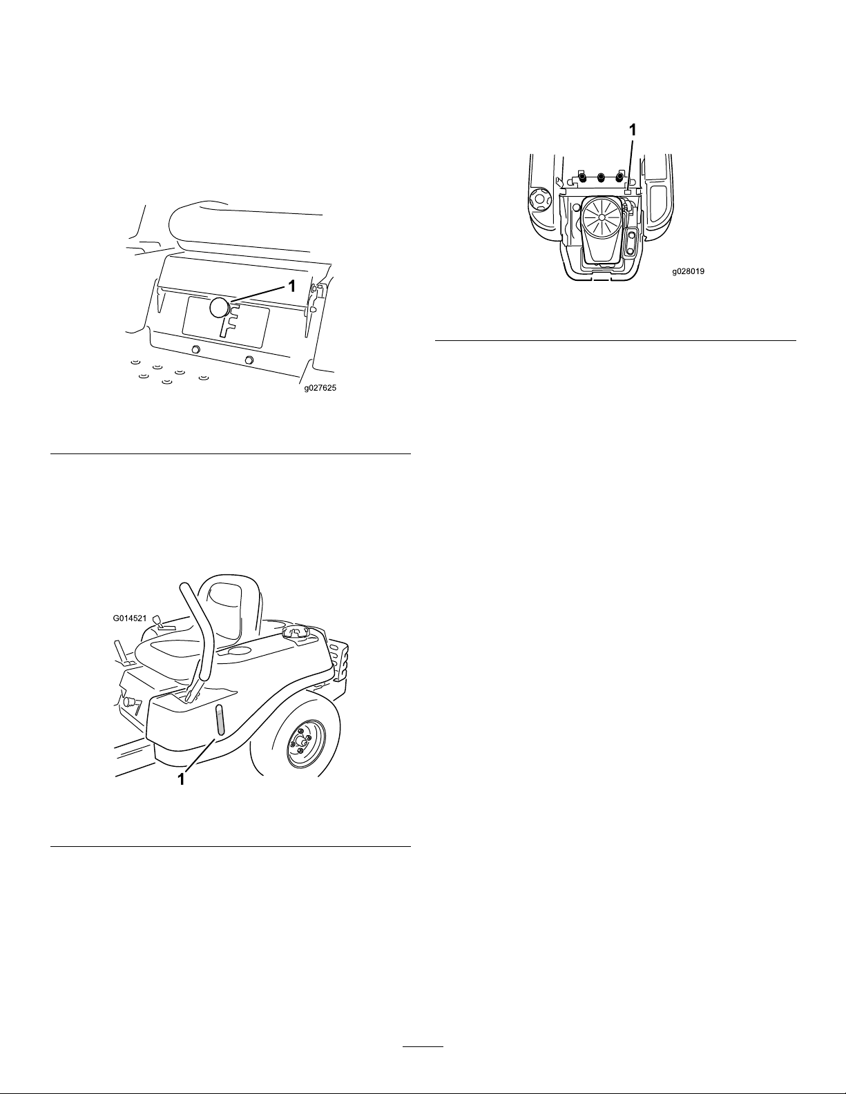
yourproductready.Figure1identiesthelocationofthe
modelandserialnumbersontheproduct.Writethenumbers
inthespaceprovided.
Figure1
Undertheseat
1.Modelandserialnumberplate
Writetheproductmodelandserialnumbersinthespace
below:
ModelNo.
SerialNo.
Thismanualidentiespotentialhazardsandhassafety
messagesidentiedbythesafetyalertsymbol(Figure2),
whichsignalsahazardthatmaycauseseriousinjuryordeath
ifyoudonotfollowtherecommendedprecautions.
©2015—TheToro®Company
8111LyndaleAvenueSouth
Bloomington,MN55420
Contactusatwww.Toro.com.
2
PrintedintheUSA.
AllRightsReserved
Page 3

Figure2
1.Safetyalertsymbol.
Thismanualuses2wordstohighlightinformation.
Importantcallsattentiontospecialmechanicalinformation
andNoteemphasizesgeneralinformationworthyofspecial
attention.
Contents
Safety...........................................................................4
SafeOperatingPractices...........................................4
ToroRidingMowerSafety........................................6
SlopeIndicator.......................................................7
SafetyandInstructionalDecals.................................8
ProductOverview.........................................................12
Controls...............................................................12
Operation....................................................................14
AddingFuel...........................................................14
CheckingtheEngine-OilLevel.................................15
BreakinginaNewMachine......................................15
ThinkSafetyFirst...................................................15
StartingtheEngine.................................................16
OperatingtheBlades...............................................17
StoppingtheEngine...............................................17
DrivingtheMachine...............................................17
StoppingtheMachine.............................................19
AdjustingtheHeight-of-Cut....................................20
PositioningtheSeat................................................20
AdjustingtheMotion-ControlLevers........................20
PushingtheMachinebyHand..................................21
TransportingtheMachine........................................21
LoadingtheMachine..............................................22
OperatingTips......................................................24
Maintenance.................................................................25
RecommendedMaintenanceSchedule(s)......................25
PremaintenanceProcedures........................................25
RaisingtheSeat......................................................25
Lubrication...............................................................25
GreasingtheBearings.............................................25
EngineMaintenance..................................................26
ServicingtheAirCleaner.........................................26
ServicingtheEngineOil..........................................27
ChangingtheEngineOilandFilter...........................28
ServicingtheSparkPlug..........................................29
FuelSystemMaintenance...........................................30
ReplacingtheIn-LineFuelFilter...............................30
ElectricalSystemMaintenance....................................31
ChargingtheBattery...............................................31
ServicingtheFuses.................................................33
DriveSystemMaintenance.........................................33
CheckingtheTirePressure......................................33
ReleasingtheElectricBrake.....................................34
CoolingSystemMaintenance......................................34
CleaningtheEngineScreen......................................34
CleaningtheEngine-CoolingFinsand
Shrouds.............................................................34
MowerMaintenance...................................................35
ServicingtheCuttingBlades.....................................35
LevelingtheMowerDeck........................................37
RemovingtheMower..............................................39
InstallingtheMower...............................................40
ReplacingtheGrassDeector..................................40
MowerBeltMaintenance............................................41
ServicingtheMowerBelt.........................................41
Cleaning...................................................................42
WashingtheUndersideoftheMower........................42
Storage........................................................................43
CleaningandStorage..............................................43
Troubleshooting...........................................................44
Schematics...................................................................46
3
Page 4

Safety
Improperuseormaintenancebytheoperatororowner
canresultininjury.Toreducethepotentialforinjury,
complywiththesesafetyinstructions,andpayattentionto
thesafetyalertsymbol,whichmeansCaution,Warning,or
Danger—“personalsafetyinstruction.”Failuretocomply
withtheinstructionsmayresultinpersonalinjuryor
death.
SafeOperatingPractices
•Neverleavearunningmachineunattended.Alwaysturn
offblades,setparkingbrake,stopengine,andremovekey
beforedismounting.
•Turnoffbladeswhennotmowing.Stoptheengine,wait
forallpartstocometoacompletestopandremovethe
keybeforecleaningthemachine,removingthegrass
catcheroruncloggingthedischargechute.
•Operatethemachineonlyindaylightorgoodarticial
light.
•Donotoperatethemachinewhileundertheinuence
ofalcoholordrugs.
Thisproductiscapableofamputatinghandsandfeetand
throwingobjects.Alwaysfollowallsafetyinstructionsto
avoidseriousinjuryordeath.
ThefollowinginstructionsareadaptedfromANSIstandard
B71.1-2012.AllthelanguagewithinthisANSIstandard
appliestothismachine;however,duetotheapplicationof
thestandardacrossmanydifferenttypesofproductssome
statementscanseemgeneralormisleading.Intheseinstances,
Torohasrenedthestatementtoconveythemeaningofthe
standardwhilebettermatchingtheproductthisOperator's
Manualpertains.Safetyinformationinadditiontothe
instructionsfoundintheANSIstandardbelowcanbefound
inToroRidingMowerSafetyattheendofthissection.
GeneralOperation
•Read,understand,andfollowallinstructionsinthe
operator'smanualandonthemachinebeforestarting.
•Donotplacehandsorfeetnearrotatingpartsorunder
themachine.Keepclearofthedischargeopeningatall
times.
•Allowonlyresponsibleadultswhoarefamiliarwiththe
instructionstooperatethemachine.
•Cleartheareaofobjectssuchasrocks,toys,wire,etc.,
whichcouldbepickedupandthrownbytheblade.
•Besuretheareaisclearofotherpeoplebeforemowing.
Stopthemachineifanyoneentersthearea.
•Watchfortrafcwhenoperatingnearorcrossing
roadways.
•Useextracarewhenloadingorunloadingthemachine
intoatrailerortruck.
•Alwaysweareyeprotectionwhenoperatingthemower.
•Dataindicatesthatoperators,age60yearsandabove,are
involvedinalargepercentageofridingmower-related
injuries.Operatorsshouldevaluatetheirabilitytooperate
theridingmowersafelyenoughtoprotectthemselvesand
othersfromseriousinjury.
•Alwaysfollowtherecommendationsforanyapplication
ofcounterweights.
•Lightningcancausesevereinjuryordeath.Iflightning
isseenorthunderisheardinthearea,donotoperate
themachine;seekshelter.
SlopeOperation
Slopesareamajorfactorrelatedtolossofcontroland
tip-overaccidents,whichcanresultinsevereinjuryordeath.
Operationonallslopesrequiresextracaution.Ifyoucannot
backuptheslopeorifyoufeeluneasyonit,donotmowit.
•Donotmowslopesgreaterthan15degrees.
•Watchforditches,holes,rocks,dips,andrisesthatchange
theoperatingangle,asroughterraincouldoverturnthe
machine.
•Nevercarrypassengers.
•Donotmowinreverseunlessabsolutelynecessary.
Alwayslookdownandbehindbeforeandwhilebacking
up.
•Beawareofthemowerdischargedirectionanddonot
pointitatanyone.Avoiddischargingmaterialagainsta
wallorobstruction.Materialmayricochetbacktoward
theoperator.Stoptheblade(s)whencrossinggravel
surfaces.
•Donotoperatethemachinewithoutdeector,discharge
coverorentiregrasscollectionsysteminplaceand
working.
•Bealert,slowdownandusecautionwhenmakingturns.
Lookbehindandtothesidebeforechangingdirections.
•Choosealowgroundspeedsoyouwillnothavetostop
whileoperatingonaslope.
•Donotmowslopeswhengrassiswet.Slippery
conditionsreducetractionandcouldcauseslidingand
lossofcontrol.
•Alwayskeepthedrivewheelsengagedwhengoingdown
slopes.
•Reducespeedanduseextremecautiononslopes.
•Donotmakesuddenturnsorrapidspeedchanges.
•Removeormarkobstaclessuchasrocks,treelimbs,etc.
fromthemowingarea.Tallgrasscanhideobstacles.
•Avoidsuddenstartswhenmowinguphillbecausethe
mowermaytipbackwards.
4
Page 5

•Beawarethatlossoftractionmayoccurgoingdownhill.
Weighttransfertothefrontwheelsmaycausedrive
wheelstoslipandcauselossofbrakingandsteering.
•Alwaysavoidsuddenstartingorstoppingonaslope.If
tireslosetraction,stopthemachine,disengagetheblades
andproceedslowlyofftheslope.
•Useextremecarewithgrasscatchersorotherattachments.
Thesecanchangethestabilityofthemachineandcause
lossofcontrol.
•Donottrytostabilizethemachinebyputtingyourfoot
ontheground.
•Donotmowneardrop-offs,ditches,steepbanksor
water.Wheelsdroppingoveredgescancauserollovers,
whichmayresultinseriousinjury,deathordrowning.
•Useawalkbehindmowerand/orahandtrimmernear
drop-offs,ditches,steepbanksorwater.
TowingSafety
•Donotattachtowedequipmentexceptatthehitchpoint.
•Followtheattachmentmanufacturer'srecommendation
forweightlimitsfortowedequipmentandtowingon
slopes.Towedweightmustnotexceedtheweightofthe
machine,operator,andballast.Usecounterweightsor
wheelweightsasdescribedintheattachment,orinthe
pullingmachineOperator’sManual.
•Neverallowchildrenorothersinorontowedequipment.
•Onslopes,theweightofthetowedequipmentmaycause
lossoftraction,increasedriskofrollover,andlossof
control.Reducethetowedweightandslowdown.
•Stoppingdistanceincreaseswiththeweightofthetowed
load.Travelslowlyandallowextradistancetostop.
•Makewideturnstokeeptheattachmentclearofthe
machine.
Children
Tragicaccidentscanoccuriftheoperatorisnotalerttothe
presenceofchildren.Childrenareoftenattractedtothe
machineandthemowingactivity.Neverassumethatchildren
willremainwhereyoulastsawthem.
•Keepchildrenoutofthemowingareaandunderthe
watchfulcareofanotherresponsibleadult,notthe
operator.
•Bealertandturnthemachineoffifchildrenenterthe
area.
•Beforeandwhilebackingorchangingdirection,look
behind,down,andside-to-sideforsmallchildren.
•Nevercarrychildren,evenwiththebladesoff.Theymay
falloffandbeseriouslyinjuredorinterferewithsafe
machineoperation.
•Childrenwhohavebeengivenridesinthepastmay
suddenlyappearinthemowingareaforanotherrideand
berunoverorbackedoverbythemower.
•Neverallowchildrentooperatethemachine.
•Useextracarewhenapproachingblindcorners,shrubs,
trees,theendofafenceorotherobjectsthatmayobscure
vision.
Service
SafeHandlingofGasoline:
Toavoidpersonalinjuryorpropertydamage,useextracare
whenhandlinggasolineandotherfuels.Theyareammable
andthevaporsareexplosive.
•Extinguishallcigarettes,cigars,pipesandothersources
ofignition.
•Useonlyanapprovedcontainer.
•Neverremovethegascaporaddfuelwhentheengineis
running.Allowtheenginetocoolbeforerefueling.
•Neverrefuelthemachineindoors.
•Neverstorethemachineorfuelcontainerinsidewhere
thereisanopename,suchasnearawaterheateror
furnace.
•Neverllcontainersinsideavehicleoronatruckor
trailerwithaplasticliner.Alwaysplacecontainersonthe
groundawayfromyourvehiclebeforelling.
•Removegas-poweredequipmentfromthetruckortrailer
andrefuelitontheground.Ifthisisnotpossible,then
refuelsuchequipmentwithaportablecontainer,rather
thanfromagasolinedispensernozzle.
•Keepthenozzleincontactwiththerimofthefueltank
orcontaineropeningatalltimesuntilthefuelingis
complete.Donotuseanozzlelock-opendevice.
•Iffuelisspilledonclothing,changeclothingimmediately.
•Neveroverllthefueltank.Replacegascapandtighten
securely.
GeneralService:
•Neveroperateamachineinsideaclosedarea.Engine
exhaustcontainscarbonmonoxide,whichisanodorless,
deadlypoisonthatcankillyou.
•Keepnutsandboltstight,especiallythebladeattachment
bolts.Keepequipmentingoodcondition.
5
Page 6

•Neverinterferewiththeintendedfunctionofasafety
deviceortoreducetheprotectionprovidedbyasafety
device.Checktheirproperoperationregularly.
•Keepthemachinefreeofgrass,leaves,orotherdebris
build-up.Cleanupoilorfuelspillagefuelsoakeddebris.
Allowthemachinetocoolbeforestoring.
•Stopandinspecttheequipmentifyoustrikeanobject.
Repair,ifnecessary,beforerestarting.
•Nevermakeanyadjustmentsorrepairswiththeengine
running.
•Grasscatchercomponentsaresubjecttowear,damage
anddeterioration,whichcouldexposemovingpartsor
allowobjectstobethrown.Frequentlycheckcomponents
andreplacewithmanufacturers'recommendedparts,
whennecessary.
•Mowerbladesaresharpandcancut.Wraptheblade(s)or
wearthickly-paddedgloves,anduseextracautionwhen
servicingthem.
•Checkforproperbrakeoperationfrequently .Adjustand
serviceasrequired.
•Maintainorreplacesafetyandinstructiondecalsas
necessary.
•UseonlygenuineTororeplacementpartstoensurethat
originalstandardsaremaintained.
ToroRidingMowerSafety
ThefollowinglistcontainssafetyinformationspecictoToro
productsorothersafetyinformationthatyoumustknowthat
maynotbeincludedintheANSIstandards.
•Stoptheengine,movethemotioncontrolleversto
neutralandoutwardtotheparkposition,disengagethe
bladecontrolswitch,removethekeyanddisconnectthe
sparkplugwire(s)beforeperforminganyservice,repairs,
maintenanceoradjustments.
•Keephands,feet,hair,andlooseclothingawayfrom
attachmentdischargearea,undersideofmowerandany
movingpartswhileengineisrunning.
•Donottouchequipmentorattachmentpartswhichmay
behotfromoperation.Allowtocoolbeforeattempting
tomaintain,adjustorservice.
•Batteryacidispoisonousandcancauseburns.Avoid
contactwithskin,eyes,andclothing.Protectyourface,
eyes,andclothingwhenworkingwithabattery.
•Batterygasescanexplode.Keepcigarettes,sparksand
amesawayfrombattery.
•Ifloadingthemachineontoatrailerortruck,useasingle,
full-widthramponly.Therampangleshouldnotexceed
15degrees.
•Removingstandardoriginalequipmentpartsand
accessoriesmayalterthewarranty,traction,andsafety
ofthemachine.FailuretouseoriginalToropartscould
causeseriousinjuryordeath.Makingunauthorized
changestotheengine,fuelorventingsystem,mayviolate
EPAandCARBregulations.
•Replaceallpartsincluding,butnotlimitedto,tires,belts,
blades,andfuelsystemcomponentswithoriginalToro
parts.
6
Page 7
SlopeIndicator
G011841
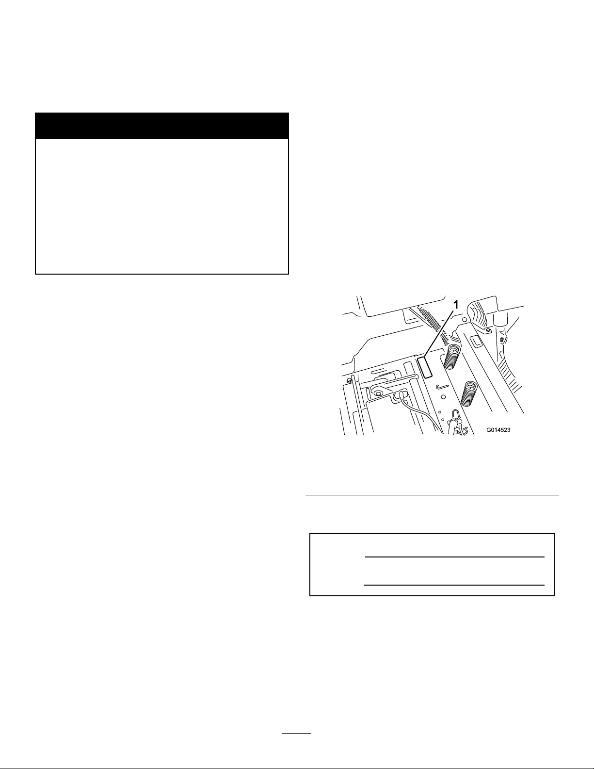
Figure3
Thispagemaybecopiedforpersonaluse.
1.Themaximumslopeyoucansafelyoperatethemachineonis15degrees.Usetheslopecharttodeterminethedegreeofslope
ofhillsbeforeoperating.Donotoperatethismachineonaslopegreaterthan15degrees.Foldalongtheappropriateline
tomatchtherecommendedslope.
2.Alignthisedgewithaverticalsurface,atree,building,fencepole,etc.
3.Exampleofhowtocompareslopewithfoldededge.
7
Page 8

SafetyandInstructionalDecals
Safetydecalsandinstructionsareeasilyvisibletotheoperatorandarelocatednearanyareaofpotential
danger.Replaceanydecalthatisdamagedorlost.
93-7009
1.Warning—don'toperatethemowerwiththedeectorupor
removed;keepthedeectorinplace.
2.Cutting/dismembermenthazardofhandorfoot,mower
blade—stayawayfrommovingparts.
106-8717
1.Readtheinstructionsbeforeservicingorperforming
maintenance.
2.Checktirepressureevery25operatinghours.
3.Greaseevery25operatinghours.
4.Engine
Manufacturer'sMark
1.Indicatesthebladeisidentiedasapartfromtheoriginal
machinemanufacturer.
119-8814
1.Parkingposition4.Neutral
2.Fast5.Reverse
3.Slow
110-6691
1.Thrownobjecthazard—keepbystandersasafedistance
fromthemachine.
2.Thrownobjecthazard,mower—donotoperatewithoutthe
deector,dischargecover,orgrasscollectionsystemin
place.
3.Cutting/dismembermentofhandorfoot—stayawayfrom
movingparts.
114-1606
1.Entanglementhazard,belt—keepallguardsinplace.
119-8815
1.Parkingposition4.Neutral
2.Fast5.Reverse
3.Slow
8
Page 9
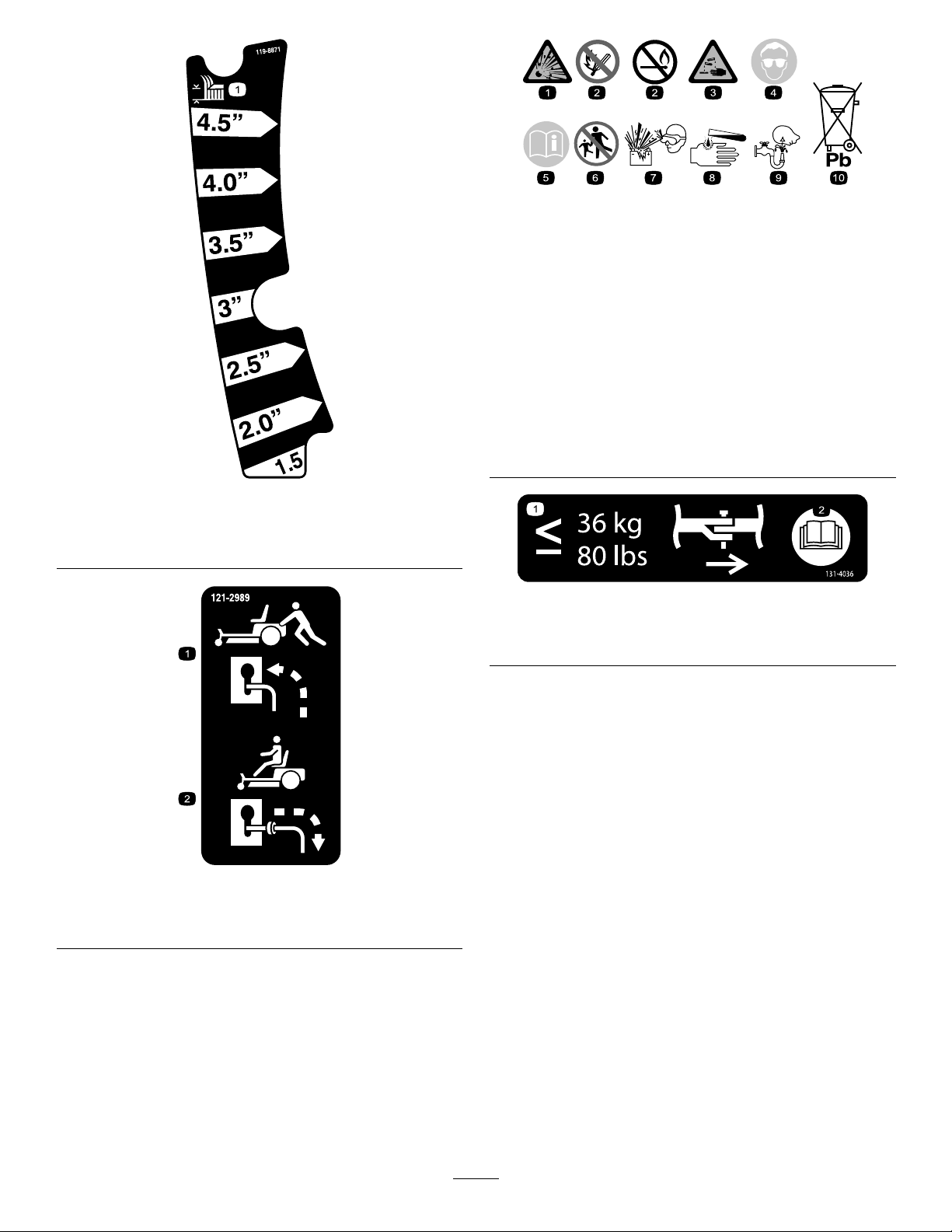
BatterySymbols
Someorallofthesesymbolsareonyourbattery
1.Explosionhazard
2.Nore,opename,or
smoking.
3.Causticliquid/chemical
burnhazard
4.Weareyeprotection9.Flusheyesimmediately
5.ReadtheOperator's
Manual.
6.Keepbystandersasafe
distancefromthebattery.
7.Weareyeprotection;
explosivegasescan
causeblindnessandother
injuries
8.Batteryacidcancause
blindnessorsevereburns.
withwaterandgetmedical
helpfast.
10.Containslead;donot
discard.
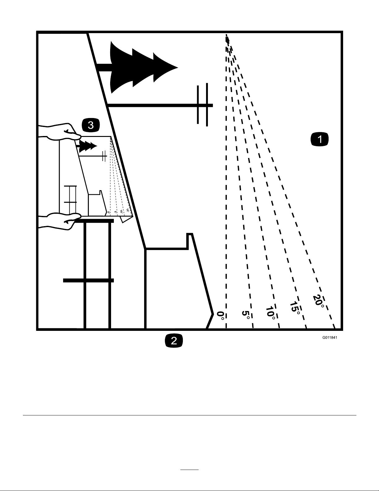
119-8871
Certainmodelsonly
1.Height-of-cut
131-4036
1.Maximumdrawbarpull36
kg(80lb)
2.ReadtheOperator's
Manual.
1.Bypassleverpositionfor
pushingthemachine
121-2989
2.Bypassleverpositionfor
operatingthemachine
9
Page 10

121-0771
1.Choke4.Slow
2.Fast
3.Continuousvariablesetting
131–3947
5.Powertake-off(PTO),Bladecontrolswitch
1.Trim—slow
2.Tow—medium
3.Mow—fast
10
Page 11
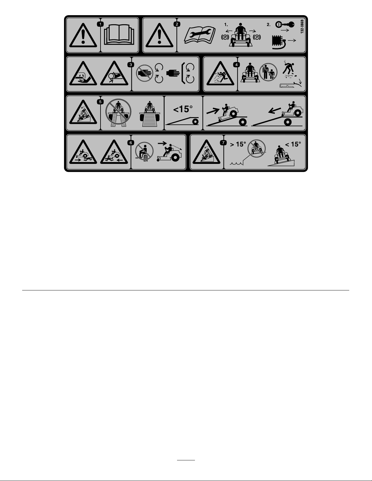
132-0869
1.Warning—readthe
Operator'sManual.
2.Warning—beforeservicing,
engagetheparkingbrake,
removethekeyandthe
sparkplugconnection.
3.Cuttinghazardofhand,
mowerblade;pinching
hazardofhand,belt—keep
handsandfeetawayfrom
movingparts;keepall
guardsandshieldsinplace.
4.Thrownobject
hazard—keepbystanders
awayfromthemachine;
removedebrisfromthe
areabeforemowing;keep
thedeectorshielddown.
5.Ramptipping
hazard—whenloading
ontoatrailer,donotuse
dualramps;onlyusea
singlerampwideenough
forthemachineandthat
hasaninclinelessthan
15degrees;backupthe
ramp(inreverse)anddrive
forwardofftheramp.
6.Bodilyharmhazard—no
riders;lookbehindyou
whenmowinginreverse.
7.Tippinghazardon
slopes—donotuseon
slopesnearopenwater;do
notuseonslopesgreater
than15degrees.
11
Page 12
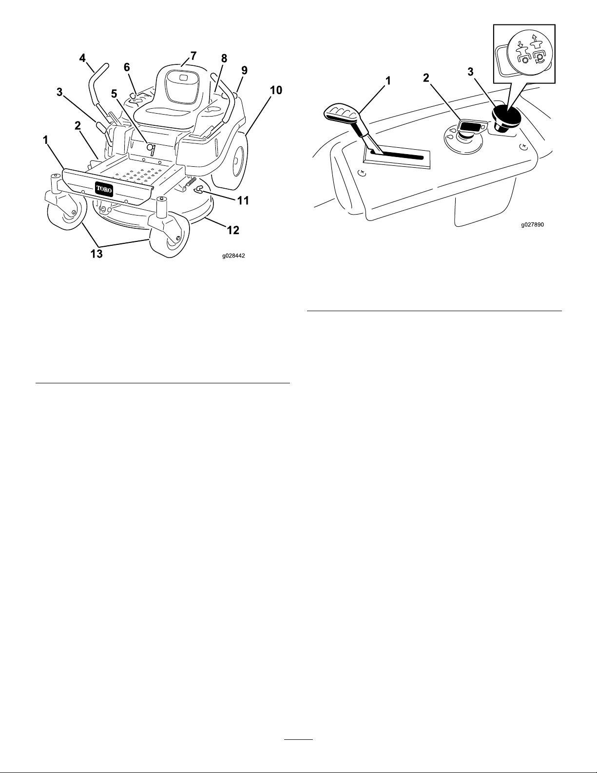
ProductOverview
Figure5
ControlPanel
Figure4
1.Footrest8.Engine
2.Deector
3.Height-of-cutlever
4.Motion-controllever
5.Smart-speedlever
6.Controlpanel
7.Operatorseat
9.Fuel-tankcap
10.Reardrivewheel
11.Washouttting
12.Mowerdeck
13.Frontcasterwheels
Controls
BecomefamiliarwithallofthecontrolsinFigure4and
Figure5beforeyoustarttheengineandoperatethemachine.
1.Throttle/Choke
2.Ignitionswitch
3.Blade-controlswitch
(powertake-off)
IgnitionSwitch
Theignitionswitchhas3positions:Off,Run,andStart.The
keywillturntoStartandmovebacktoRunuponrelease.
TurningthekeytotheOffpositionwillstoptheengine;
however,alwaysremovethekeywhenleavingthemachine
topreventsomeonefromaccidentallystartingtheengine
(Figure5).
Throttle/ChokeControl
Thethrottleandchokearecombinedintoonecontrollever.
Thethrottlecontrolstheenginespeedandithasacontinuous
variablesettingfromSlowtoFast.Engagethechokeby
movingtheleverpasttheFastsettinguntilitstops(Figure5).
Itmaybenecessarytoholdtheleveragainstthestop,inthe
chokeposition,whiletryingtostarttheengine.
Note:Awarmorhotenginemaynotrequirechoking.
Blade-ControlSwitch(PowerTake-off)
Theblade-controlswitch,representedbyapowertake-off
(PTO)symbol,engagesanddisengagespowertothemower
blades(Figure5).
Motion-ControlLeversandPark
Position
Themotion-controlleversarespeed-sensitivecontrolsof
independent-wheelmotors.Movingaleverforwardor
backwardturnsthewheelonthesamesideforwardorin
reverse;wheelspeedisproportionaltotheamountthelever
ismoved.Movethecontrolleversoutwardfromthecenter
12
Page 13
totheparkpositionandexitthemachine(Figure15).Always
G014521
1
g028019
1
positionthemotion-controlleversintotheparkposition
whenyoustopthemachineorleaveitunattended.
SmartSpeed™ControlSystemLever
TheSmartSpeed™Control-Systemlever,locatedbelowthe
operatingposition,givestheoperatorachoicetodrivethe
machineat3speedranges—trim,tow ,andmow(Figure6).
Figure6
1.Smart-speedlever
HourMeter
Thehourmeterrecordsthenumberofhourswhenthe
operatorisintheseatandtheignitionswitchisintheON
position(Figure8).
Figure8
1.Hourmeterlocationbehindtheseat
Fuel-PresenceWindow
Thefuelwindowlocatedontheleft-handsideofthemachine,
canbeusedtoverifythepresenceofgasolineinthetank
(Figure7).
Figure7
1.Fuel-presencewindow
Height-of-CutLever
Theheight-of-cutleverallowstheoperatortolowerand
raisethedeckfromtheseatedposition.Whentheleveris
movedup(towardtheoperator),thedeckisraisedfromthe
ground,andwhenmoveddown(awayfromtheoperator),it
isloweredtowardtheground.Onlyadjusttheheight-of-cut
whilethemachineisnotmoving(Figure4).
13
Page 14

Operation
Note:Determinetheleftandrightsidesofthemachine
fromthenormaloperatingposition.
AddingFuel
•Forbestresults,useonlyclean,fresh(lessthan30days
old),unleadedgasolinewithanoctaneratingof87or
higher((R+M)/2ratingmethod).
•Ethanol:Gasolinewithupto10%ethanol(gasohol)
or15%MTBE(methyltertiarybutylether)byvolume
isacceptable.EthanolandMTBEarenotthesame.
Gasolinewith15%ethanol(E15)byvolumeisnot
approvedforuse.Neverusegasolinethatcontains
morethan10%ethanolbyvolume,suchasE15
(contains15%ethanol),E20(contains20%ethanol),or
E85(containsupto85%ethanol).Usingunapproved
gasolinemaycauseperformanceproblemsand/orengine
damagewhichmaynotbecoveredunderwarranty.
•Donotusegasolinecontainingmethanol.
•Donotstorefueleitherinthefueltankorfuelcontainers
overthewinterunlessafuelstabilizerisused.
•Donotaddoiltogasoline.
DANGER
Incertainconditionsduringfueling,static
electricitycanbereleasedcausingasparkwhich
canignitethegasolinevapors.Areorexplosion
fromgasolinecanburnyouandothersandcan
damageproperty.
•Alwaysplacegasolinecontainersontheground
awayfromyourvehiclebeforelling.
•Donotllgasolinecontainersinsideavehicleor
onatruckortrailerbedbecauseinteriorcarpets
orplastictruckbedlinersmayinsulatethe
containerandslowthelossofanystaticcharge.
•Whenpractical,removegas-poweredequipment
fromthetruckortrailerandrefueltheequipment
withitswheelsontheground.
•Ifthisisnotpossible,thenrefuelsuch
equipmentonatruckortrailerfromaportable
container,ratherthanfromagasolinedispenser
nozzle.
•Ifagasolinedispensernozzlemustbeused,
keepthenozzleincontactwiththerimofthe
fueltankorcontaineropeningatalltimesuntil
fuelingiscomplete.
DANGER
Incertainconditions,gasolineisextremely
ammableandhighlyexplosive.Areorexplosion
fromgasolinecanburnyouandothersandcan
damageproperty.
•Fillthefueltankoutdoors,inanopenarea,
whentheengineiscold.Wipeupanygasoline
thatspills.
•Neverllthefueltankinsideanenclosedtrailer.
•Donotllthefueltankcompletelyfull.Add
gasolinetothefueltankuntilthelevelis6to13
mm(1/4to1/2inch)belowthebottomofthe
llerneck.Thisemptyspaceinthetankallows
gasolinetoexpand.
•Neversmokewhenhandlinggasoline,andstay
awayfromanopenameorwheregasoline
fumesmaybeignitedbyaspark.
•Storegasolineinanapprovedcontainerand
keepitoutofthereachofchildren.Neverbuy
morethana30-daysupplyofgasoline.
•Donotoperatewithoutentireexhaustsystemin
placeandinproperworkingcondition.
WARNING
Gasolineisharmfulorfatalifswallowed.Long-term
exposuretovaporscancauseseriousinjuryand
illness.
•Avoidprolongedbreathingofvapors.
•Keepfaceawayfromnozzleandgastankor
conditionerbottleopening.
•Avoidcontactwithskin;washoffspillagewith
soapandwater.
UsingStabilizer/Conditioner
Useafuelstabilizer/conditionerinthemachinetoprovide
thefollowingbenets:
•Keepsgasolinefreshduringstorageof90daysorless.
Forlongerstorageitisrecommendedthatthefueltank
bedrained.
•Cleanstheenginewhileitruns
•Eliminatesgum-likevarnishbuildupinthefuelsystem,
whichcauseshardstarting
Important:Donotusefueladditivescontaining
methanolorethanol.
Addthecorrectamountofgasstabilizer/conditionerto
thegas.
Note:Afuelstabilizer/conditionerismosteffective
whenmixedwithfreshgasoline.T ominimizethechance
14
Page 15
ofvarnishdepositsinthefuelsystem,usefuelstabilizer
g027243
A
B
E
D
C
atalltimes.
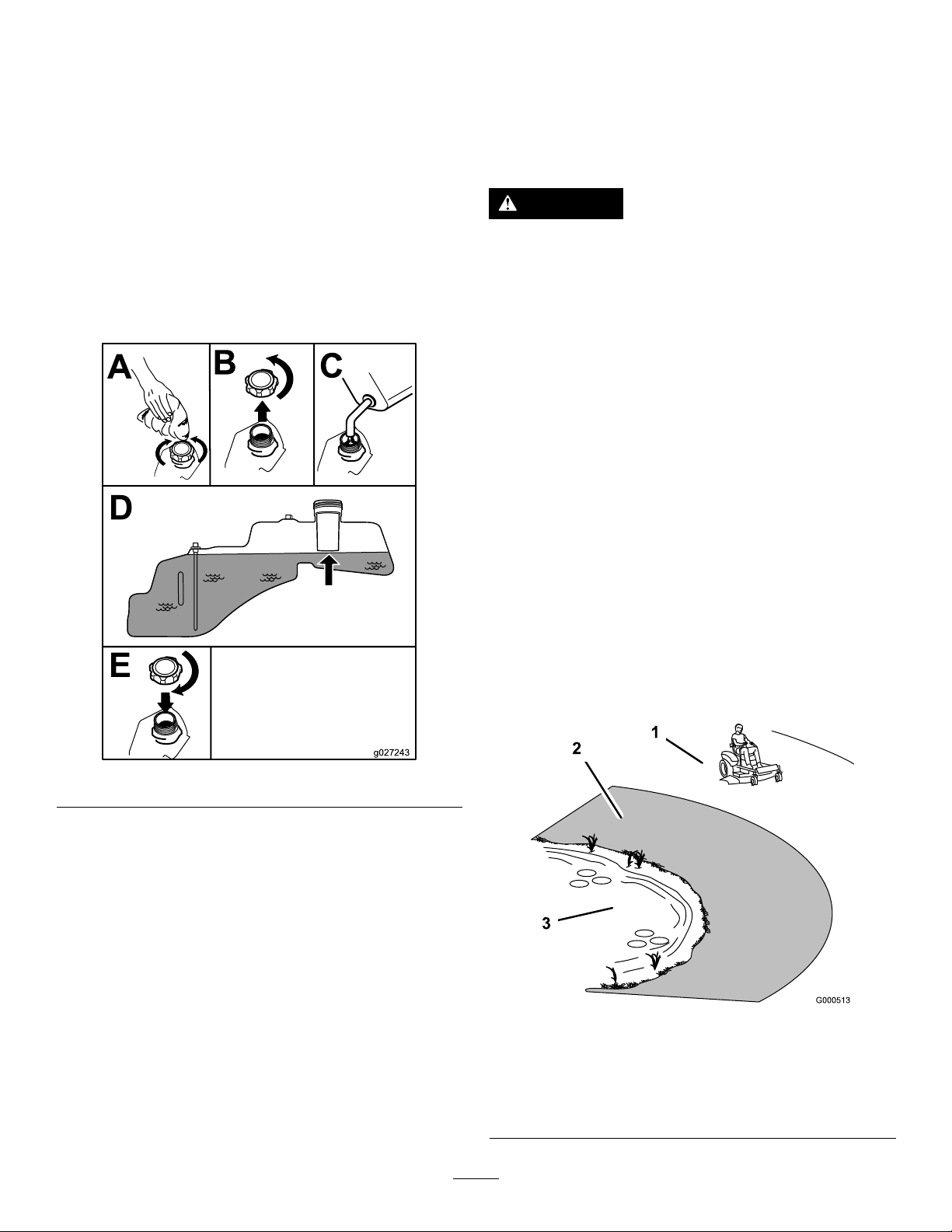
FillingtheFuelTank
Note:Ensurethattheengineisshutoffandthemotion
controlsareintheparkedposition.
ThinkSafetyFirst
OperatingSafety
Pleasecarefullyreadallofthesafetyinstructionsanddecals
inthesafetysection.Knowingthisinformationcouldhelp
you,yourfamily ,pets,orbystandersavoidinjury.
Note:Youcanusethefuelwindowtoverifythepresenceof
gasolinebeforellingthetank(Figure9).
Important:Donotoverllfueltank.Fillthefueltank
tothebottomofthellerneck.Theemptyspaceinthe
tankallowsthefueltoexpand.Overllingmayresultin
fuelleakage,damagetotheengine,ordamagetothe
emissionssystem.
DANGER
Mowingonwetgrassorsteepslopescancause
slidingandlossofcontrol.
Wheelsdroppingoveredgescancauserollovers,
whichmayresultinseriousinjury,death,or
drowning.
Alossoftractionisalossofsteeringcontrol.
Toavoidlossofcontrolandpossibilityofrollover:
•Donotmowneardrop-offsornearwater.
•Donotmowslopesgreaterthan15degrees.
•Reducethespeedanduseextremecautionon
slopes.
•Whenmowingslopes,graduallyworkfrom
lowertohigherareasontheincline.
•Avoidsuddenturnsorrapidspeedchanges.
•Turnup,intoaninclinewhenchanging
directionsonslopes.Turningdowntheslope
reducestraction.
Figure9
CheckingtheEngine-OilLevel
Beforeyoustarttheengineandusethemachine,check
theoillevelintheenginecrankcase;refertoCheckingthe
Engine-OilLevel(page27).
BreakinginaNewMachine
Newenginestaketimetodevelopfullpower.Mowerdecks
anddrivesystemshavehigherfrictionwhennew,placing
additionalloadontheengine.Allow40to50hoursof
break-intimefornewmachinestodevelopfullpowerand
bestperformance.
•Attachmentschangethehandlingcharacteristics
ofthemachine.Useextracautionwhenusing
attachmentswiththemachine.
Figure10
1.Safezone—usethe
TimeCutterhere
2.Useawalk-behindmower
and/orhandtrimmernear
drop-offsandwater.
3.Water
15
Page 16

CAUTION
G009027
1
2
Thismachineproducessoundlevelsinexcessof85
dBAattheoperatorsearandcancausehearingloss
throughextendedperiodsofexposure.
4.Moveeithermotion-controllevertothecenter,
unlockedposition.
5.Trystartingtheengine;theengineshouldnotcrank.
6.Repeatwiththeothermotion-controllever.
Wearhearingprotectionwhenoperatingthis
machine.
Theuseofprotectiveequipmentforeyes,ears,feet,andhead
isrecommended.
Figure11
1.Wearsafetyglasses
2.Wearhearingprotection
UnderstandingtheSafety-Interlock
System
WARNING
Ifsafety-interlockswitchesaredisconnectedor
damaged,themachinecouldoperateunexpectedly
causingpersonalinjury.
•Donottamperwiththeinterlockswitches.
•Checktheoperationoftheinterlockswitches
daily,andreplaceanydamagedswitchesbefore
operatingthemachine.
7.Whilesittingontheseat,movetheblade-control
switchtoOff,andlockthemotion-controlleversin
theparkposition.
8.Starttheengine.
9.Whiletheengineisrunning,engagetheblade-control
switch,andriseslightlyfromtheseat.
Note:Theengineshouldstop.
10.Whilesittingontheseat,movetheblade-control
switchtoOff,andlockthemotion-controlleversin
theparkposition.
11.Starttheengine.
12.Whiletheengineisrunning,movethemotion-control
leverstothecenter,unlockedposition,engagethe
blade-controlswitch,andriseslightlyfromtheseat.
Note:Theengineshouldstop.
StartingtheEngine
Important:Donotengagethestarterformorethan
5secondsatatime.Engagingthestartermotorfor
morethan5secondscandamagethestartermotor.If
theenginefailstostart,wait10secondsbeforeoperating
theenginestarteragain.
Note:Itmaybenecessarytoholdtheleveragainstthestop,
inthechokeposition,whiletryingtostarttheengine(Figure
12).
Thesafety-interlocksystemisdesignedtopreventtheengine
fromstartingunless:
•Thebladesaredisengaged.
•Themotion-controlleversareintheparkposition.
Thesafety-interlocksystemalsoisdesignedtostoptheengine
wheneverthecontrolleversareoutoftheparkpositionand
yourisefromtheseat.
TestingtheSafety-InterlockSystem
Testthesafety-interlocksystembeforeyouusethemachine
eachtime.Ifthesafetysystemdoesnotoperateasdescribed
below,haveanAuthorizedServiceDealerrepairthesafety
systemimmediately.
1.Whilesittingontheseat,withthecontrolleversinpark
position,andmovetheblade-controlswitchtoOn.
2.Trystartingtheengine;theengineshouldnotcrank.
3.Whilesittingontheseat,movetheblade-control
switchtoOff.
16
Page 17

g027535
B
C
D
E
A
G
F
g027245
B
C
A
DisengagingtheBlades
g027247
Figure13
Figure12
OperatingtheBlades
Theblade-controlswitch,representedbyapowertake-off
(PTO)symbol,engagesanddisengagespowertothemower
blades.Thisswitchcontrolspowertoanyattachmentsthat
drawpowerfromtheengine,includingthemowerdeckand
cuttingblades.
EngagingtheBlades
Important:Donotengagethebladeswhenparkedin
tallgrass;beltorclutchdamagecanoccur.
Note:Alwaysengagethebladeswiththethrottleinthe
Fastposition.
Figure14
StoppingtheEngine
1.Disengagethebladesbymovingtheblade-control
switchtoOff(Figure14).
2.MovethethrottlelevertotheFastposition.
3.TurntheignitionkeytoOffandremovethekey.
DrivingtheMachine
Drivingthemachinebenetsfromanunderstandingof
whatzero-turn-radiusmowermeans.Thedrivewheelsturn
independently,poweredbyhydraulicmotorsoneachaxle;
henceonesidecanturninreversewhiletheotherturns
forwardcausingthemachinetospinratherthanturn.This
vastlyimprovesthemachinemaneuverabilitybutmayrequire
someadjustmentiftheoperatorisunfamiliar.
17
Page 18

WARNING
Themachinecanspinveryrapidly.Theoperator
maylosecontrolofthemachineandcausepersonal
injuryordamagetothemachine.
•Usecautionwhenmakingturns.
•Slowthemachinedownbeforemakingsharp
turns.
Thethrottlecontrolregulatestheenginespeedasmeasured
inrpm(revolutionsperminute).Placingthethrottlecontrol
intheFastpositioncanbebestforperformance.Formost
applications,operatinginthefull-throttlepositionisdesirable.
UsingtheSmartSpeed
TM
Control
System
TheSmartSpeed
operatingposition(Figure16),givestheoperatorachoice
todrivethemachineat3groundspeedranges—trim,tow ,
andmow .
1.Smartspeedlever
Tochangespeeds,dothefollowing:
1.Movethemotioncontrolleverstoneutralandoutward
totheparkposition.
2.Disengagethebladecontrolswitch
3.Adjustthelevertothedesiredposition.
TM
Control-Systemlever,locatedbelowthe
Figure16
Figure15
1.Park(brake)position
2.Center,unlockposition5.Frontofthemachine
3.Forward
4.Backward
Thefollowingareonlyrecommendationsforuse.
Adjustmentswillvarybygrasstype,moisturecontent,and
theheightofthegrass.
Suggested
uses:
ParkingX
Heavy,wet
grass
TrainingX
BaggingX
MulchingX
Normal
mowing
TransportX
TrimTowMow
X
X
Trim
Thisisthelowestspeed.Thesuggestedusesforthisspeed
areasfollows:
•Parking
•Heavy,wetgrassmowingconditions
•Training
Tow
Thisisthemediumspeed.Thesuggestedusesforthisspeed
areasfollows:
18
Page 19

•Bagging
G008952
G008953
DrivingBackward
•Mulching
Mow
Thisisthefastestspeed.Thesuggestedusesforthisspeed
areasfollows:
•Normalmowing
•Transportingthemachine
DrivingForward
1.Movetheleverstothecenter,unlockedposition.
2.Togoforward,slowlypushthemotion-controllevers
forward(Figure17).
Note:Alwaysusecautionwhenbackingupandturning.
1.Movetheleverstothecenter,unlockedposition.
2.Togobackward,lookbehindyouanddown,asyou
slowlypullthemotion-controlleversrearward(Figure
18).
Figure18
Figure17
Togostraight,applyequalpressuretoboth
motion-controllevers(Figure17).
Toturn,releasepressureonthemotion-controllever
towardthedirectionyouwanttoturn(Figure17).
Thefartheryoumovethemotion-controlleversin
eitherdirection,thefasterthemachinewillmovein
thatdirection.
Tostop,pullthemotion-controlleverstoneutral.
Togostraight,applyequalpressuretoboth
motion-controllevers(Figure18).
Toturn,releasethepressureonthemotion-control
levertowardthedirectionyouwanttoturn.
Tostop,pushthemotion-controlleverstoneutral.
StoppingtheMachine
Tostopthemachine,movethemotion-controlleversto
neutralandoutwardtotheparkposition,disengagethe
blade-controlswitch,movethethrottletotheFastposition,
andturntheignitionkeytooff.
Note:Remembertoremovethekeyfromtheignitionswitch.
WARNING
Childrenorbystandersmaybeinjuredifthey
moveorattempttooperatethemowerwhileitis
unattended.
Alwaysremovetheignitionkeyandmovethe
motion-controlleversoutwardtotheparkposition
whenleavingthemachineunattended,evenifjust
forafewminutes.
19
Page 20

AdjustingtheHeight-of-Cut
g027249
B
C
A
g027252
B
A
Note:Thetransportpositionisthehighestheight-of-cut
positionorcuttingheight(115mm(4.5inches))asshown
inFigure19.
Height-of-cutiscontrolledbytheleverlocatedtotherightof
theoperatingposition(Figure19).
PositioningtheSeat
Figure20
AdjustingtheMotion-Control Levers
AdjustingtheHeight
Themotion-controlleverscanbeadjustedhigherorlowerfor
maximumoperatorcomfort(Figure21).
Figure19
Figure21
20
Page 21

AdjustingtheTilt
g017303
1 2
3
Themotion-controlleverscanbetiltedforeoraftfor
maximumoperatorcomfort.
1.Loosentheupperboltholdingthecontrollevertothe
control-armshaft.
2.Loosenthelowerboltjustenoughtopivotthecontrol
leverforeoraft(Figure21).Tightenbothboltsto
securethecontrolinthenewposition.
3.Repeattheadjustmentfortheoppositecontrollever.
PushingtheMachinebyHand
Important:Alwayspushthemachinebyhand.Donot
towthemachine,becausedamagemayoccur.
Thismachinehasanelectric-brakemechanism,andtopush
themachine,theignitionkeyneedstobeintheRunposition.
Thebatteryneedstobechargedandfunctioningforthe
electricbraketobedisengage.
PushingtheMachine
1.Parkthemachineonalevelsurface,anddisengagethe
blade-controlswitch.
2.Movethemotion-controlleversoutwardtothepark
position,stoptheengine,andwaitforallmovingparts
tostopbeforeleavingtheoperatingposition.
3.Locatethebypassleversontheframeonbothsidesof
theengine.
4.Movethebypassleversforwardthroughthekeyhole
anddowntolocktheminplace(Figure22).
Note:Ensurethisisdoneforeachlever.
5.Movethemotion-controlleversinwardtotheneutral
positionandturntheignitionkeytotheRunposition.
Note:Donotstartthemachine.
Note:Themachineisnowabletobepushedbyhand.
Figure22
1.Bypass-leverlocations
2.Leverpositionfor
operatingthemachine
6.Whennished,ensurethatthekeyhasbeenreturnedto
theStoppositiontoavoiddrainingthebatterycharge.
Note:Ifthemachinefailstomove,theelectricbrakemay
stillbeengaged.Ifnecessary,theelectricbrakecanbereleased
manually;refertoReleasingtheElectricBrake(page34).
3.Leverpositionforpushing
themachine
OperatingtheMachine
Movethebypassleversrearwardthroughthekeyholeand
downtolocktheminplaceasshowninFigure22.
Note:Ensurethisisdoneforeachlever.
TransportingtheMachine
Useaheavy-dutytrailerortrucktotransportthemachine.
Ensurethatthetrailerortruckhasallnecessarybrakes,
lighting,andmarkingasrequiredbylaw .Pleasecarefullyread
allthesafetyinstructions.Knowingthisinformationcould
helpyou,yourfamily,pets,orbystandersavoidinjury.
WARNING
Drivingonthestreetorroadwaywithoutturn
signals,lights,reectivemarkings,oraslow
movingvehicleemblemisdangerousandcanlead
toaccidentscausingpersonalinjury.
Donotdrivemachineonapublicstreetorroadway.
Totransportthemachine:
1.Ifusingatrailer,connectittothetowingvehicleand
connectthesafetychains.
2.Ifapplicable,connectthetrailerbrakes.
3.Loadthemachineontothetrailerortruck.
21
Page 22

4.Stoptheengine,removethekey,setthebrake,and
closethefuelvalve.
5.Tiedownthemachinenearthefrontcasterwheelsand
therearbumper(Figure23).
WARNING
Loadingamachineontoatrailerortruckincreases
thepossibilityoftip-overandcouldcauseserious
injuryordeath.
•Useextremecautionwhenoperatingamachine
onaramp.
•Useonlyafull-widthramp;donotuseindividual
rampsforeachsideofthemachine.
•Donotexceeda15-degreeanglebetweenthe
rampandthegroundorbetweentherampand
thetrailerortruck.
Figure23
LoadingtheMachine
Useextremecautionwhenloadingorunloadingmachines
ontoatraileroratruck.Useafull-widthrampthatiswider
thanthemachineforthisprocedure.Backuprampsand
driveforwarddownramps(Figure24).
Figure24
1.Backupramps
Important:Donotusenarrowindividualrampsfor
eachsideofthemachine.
2.Driveforwarddownramps
•Ensurethelengthoframpisatleastfourtimes
(4X)aslongastheheightofthetrailerortruck
bedtotheground.Thiswillensurethatramp
angledoesnotexceed15degreesonatground.
•Backuprampsanddriveforwarddownramps.
•Avoidsuddenaccelerationordecelerationwhile
drivingthemachineonarampasthiscould
causealossofcontroloratip-oversituation.
Ensuretherampislongenoughsothattheanglewiththe
grounddoesnotexceed15degrees(Figure25).Onat
ground,thisrequiresaramptobeatleastfourtimes(4X)as
longastheheightofthetrailerortruckbedtotheground.A
steeperanglemaycausemowercomponentstogetcaughtas
theunitmovesfromtheramptothetrailerortruck.Steeper
anglesmayalsocausethemachinetotiporlosecontrol.If
loadingonornearaslope,positionthetrailerortrucksothat
itisonthedownsideoftheslopeandtherampextendsup
theslope.Thiswillminimizetherampangle.
22
Page 23

g027996
5
1
2
6
Figure25
1.Full-widthrampinstowed
position
2.Sideviewoffull-width
rampinloadingposition
3.Notgreaterthan
15degrees
4.Rampisatleastfourtimes
(4X)aslongastheheight
ofthetrailerortruckbed
totheground
5.H=heightofthetraileror
truckbedtotheground
6.Trailer
23
Page 24

OperatingTips
UsingtheFastThrottleSetting
Forbestmowingandmaximumaircirculation,operate
theengineattheFastthrottleposition.Airisrequiredto
thoroughlycutgrassclippings,sodonotsettheheight-of-cut
solowastototallysurroundthemowerbyuncutgrass.
Alwaystrytohaveonesideofthemowerfreefromuncut
grass,whichallowsairtobedrawnintothemower.
UsingtheSmartSpeed™Control
System
TheSmartSpeed™Control-Systemlever,locatedbelowthe
operatingposition,givestheoperatorachoicetodrivethe
machineat3speedranges—trim,mow,andtow .Anoperator
canbenetfromthetrimspeedsettingwhenmaneuvering
themachineintightspacesoroperatingarounddelicate
landscapes.Thetrimsettingcanalsobeusedtooperatethe
machineatahighthrottlesettingandbladespeed,whilestill
beingabletoreducethegroundspeedtoincreasethequality
ofcut.
CuttingLongGrass
Ifthegrassiseverallowedtogrowslightlylongerthan
normal,orifitcontainsahighdegreeofmoisture,raisethe
cuttingheighthigherthanusualandcutthegrassatthis
setting.Thencutthegrassagainusingthelower,normal
setting.
Stopping
Ifyoumuststoptheforwardmotionofthemachinewhile
mowing,aclumpofgrassclippingsmaydropontoyour
lawn.Toavoidthis,moveontoapreviouslycutareawiththe
bladesengagedoryoucandisengagethemowerdeckwhile
movingforward.
KeepingtheUndersideoftheMower
Clean
Cleanclippingsanddirtfromtheundersideofthemower
aftereachuse.Ifgrassanddirtbuildupinsidethemower,
cuttingqualitywilleventuallybecomeunsatisfactory.
CuttingaLawnfortheFirstTime
Cutgrassslightlylongerthannormaltoensurethatthe
cuttingheightofthemowerdoesnotscalpanyuneven
ground.However,thecuttingheightusedinthepastis
generallythebestonetouse.Whencuttinggrasslongerthan
sixinchestall,youmaywanttocutthelawntwicetoensure
anacceptablequalityofcut.
Cutting1/3oftheGrassBlade
Itisbesttocutonlyabout1/3ofthegrassblade.Cutting
morethanthatisnotrecommendedunlessgrassissparse,or
itislatefallwhengrassgrowsmoreslowly.
AlternatingtheMowingDirection
Alternatethemowingdirectiontokeepthegrassstanding
straight.Thisalsohelpsdisperseclippingswhichenhances
decompositionandfertilization.
MowingatCorrectIntervals
Normally,mowevery4days.But,remember,grassgrowsat
differentratesatdifferenttimes.Sotomaintainthesame
cuttingheight,whichisagoodpractice,andmowmoreoften
inearlyspring.Asthegrassgrowthrateslowsinmidsummer,
mowlessfrequently.Ifyoucannotmowforanextended
period,rstmowatahighcuttingheight,thenmowagain2
dayslateratalowerheightsetting.
MaintainingtheBlade(s)
Maintainasharpbladethroughoutthecuttingseasonbecause
asharpbladecutscleanlywithouttearingorshreddingthe
grassblades.Tearingandshreddingturnsgrassbrownat
theedges,whichslowsgrowthandincreasesthechanceof
disease.Checkthemowerbladesaftereachuseforsharpness,
andforanywearordamage.Filedownanynicksandsharpen
thebladesasnecessary.Ifabladeisdamagedorworn,replace
itimmediatelywithagenuineTororeplacementblade.
AvoidingCuttingTooLow
Ifthecuttingwidthofthemoweriswiderthanthemower
youpreviouslyused,raisethecuttingheighttoensurethat
uneventurfisnotcuttooshort.
24
Page 25

Maintenance
Note:Determinetheleftandrightsidesofthemachinefromthenormaloperatingposition.
RecommendedMaintenanceSchedule(s)
MaintenanceService
Interval
Aftertherst5hours
Beforeeachuseordaily
Aftereachuse
Every25hours
Every50hours
Every100hours
Beforestorage
MaintenanceProcedure
•Changetheengineoilandlter.
•Checkthesafety-interlocksystem.
•Cleanandchecktheaircleanerfoamelement.
•Checktheengineoillevel.
•Cleantheengineair-intakescreen.
•Checkthecuttingblades.
•Inspectthegrassdeectorfordamage.
•Cleanthemower-deckhousing.
•Greaseallthelubricationpoints.
•Checktirepressure.
•Checkthebeltsforwear/cracks.
•Replacetheaircleanerpaperelement.
•Checkthesparkplug.
•Changetheengineoil(changeitmoreoftenunderaheavyloadorinhigh
temperatures).
•Changetheengine-oillter.
•Replacethesparkplug.
•Replacethein-linefuellter
•Cleantheengine-coolingnsandshrouds.
•Chargethebatteryanddisconnectbatterycables.
•Performallmaintenanceprocedureslistedabovebeforestorage.
•Paintanychippedsurfaces.
CAUTION
Ifyouleavethekeyintheignitionswitch,someonecouldaccidentlystarttheengineandseriouslyinjure
youorotherbystanders.
Removethekeyfromtheignitionanddisconnectthewirefromthesparkplugbeforeyoudoany
maintenance.Setthewireasidesothatitdoesnotaccidentallycontactthesparkplug.
Premaintenance
Lubrication
Procedures
GreasingtheBearings
RaisingtheSeat
Makesurethatthemotion-controlleversarelockedinthe
parkposition,andlifttheseatforward.
Thefollowingcomponentscanbeaccessedbyraisingtheseat:
•Serialplate
•Servicedecal
•Seat-adjustmentbolts
•Fuellter
•Batteryandbatterycables
ServiceInterval:Every25hours—Greaseallthelubrication
points.
GreaseType:No.2GeneralPurpose,Lithium-BaseGrease
1.Parkthemachineonalevelsurface,anddisengagethe
blade-controlswitch.
2.Movethemotion-controlleversoutwardtothepark
position,stoptheengine,removethekey ,andwaitfor
allmovingpartstostopbeforeleavingtheoperating
position.
25
Page 26

3.Cleanthegreasettings(Figure26andFigure27)with
1
G014522
G017862
arag.
EngineMaintenance
Note:Makesuretoscrapeanypaintoffofthefront
ofthetting(s).
Figure26
1.Frontcastertire
ServicingtheAirCleaner
ServiceInterval:Beforeeachuseordaily—Cleanandcheck
theaircleanerfoamelement.
Every50hours—Replacetheaircleanerpaper
element.
Note:Servicetheaircleanermorefrequentlyiftheoperating
conditionsareextremelydustyorsandy.
RemovingtheFoamandPaper
Elements
1.Disengagetheblade-controlswitch(PTO).
2.Stoptheengine,waitforallmovingpartstostop,and
removethekeybeforeleavingtheoperatingposition.
3.Cleanaroundtheaircleanertopreventdirtfrom
gettingintotheengineandcausingdamage.
4.Removetheair-cleanercoverbyunscrewingthe2
knobs(Figure28).
Figure27
Locatedontheseat-panunderside
1.Readtheinstructions
beforeservicingor
performingmaintenance
2.Checkthetirepressure
every25operatinghours
3.Greaseevery25operating
hours
4.Engine
4.Connectagreaseguntoeachtting(Figure26and
Figure27).
5.Pumpgreaseintothettingsuntilgreasebeginsto
oozeoutofthebearings.
Figure28
1.Air-cleanercover2.Knobs
5.Carefullyremovethefoamandpaperlterelements
fromtheair-cleanerhousing(Figure29).
26
Page 27

Figure29
SAE 5W -30, 10W -30
SAE 30
SYNTHETIC 5W -20, 5W -30, 10W -30
g029683
1.Foamelement2.Paperelement
6.Separatethefoamandpaperelements.
ServicingtheEngineOil
OilType:Detergentoil(APIserviceSF ,SG,SH,SJ,or
higher)
CrankcaseCapacity:1.0L(34oz)whenyoudonotchange
thelter;1.05L(36oz)whenyouchangethelter.
Viscosity:Seethetablebelow.
CleaningtheFoamandPaperElements
FoamElement:
1.Washthefoamelementinliquidsoapandwarmwater.
2.Whentheelementisclean,rinseitthoroughly.
3.Drytheelementbysqueezingitinacleancloth.
Note:Donotoiltheelement.
Important:Replacethefoamelementifitistorn
orworn.
4.Installthefoamelementontoacleanpaperelement.
PaperElement:
1.Tapthepaperelementonasolid,atsurface,andblow
itoutfromtheinsidewithcompressedairtoremove
dustanddirt.
2.Inspecttheelementfortears,anoilylm,anddamage
totherubberseal.
Important:Donotcleanthepaperelementwith
liquids,suchassolvents,gasoline,orkerosene.
Replacethepaperelementifitisdamagedor
cannotbecleanedthoroughly.
3.Cleantheinsideoftheair-cleanercoverofalldirt,dust,
anddebris.
Figure30
CheckingtheEngine-OilLevel
ServiceInterval:Beforeeachuseordaily
Note:Checktheoilwhentheengineiscold.
WARNING
Contactwithhotsurfacesmaycausepersonal
injury.
Keephands,feet,face,clothingandotherbody
partsawaythemuferandotherhotsurfaces.
Important:Donotoverllthecrankcasewithoiland
runtheengine;enginedamagemayresult.
1.Parkthemachineonalevelsurface.
2.Disengagetheblade-controlswitch(PTO).
3.Stoptheengine,waitforallmovingpartstostop,and
removethekeybeforeleavingtheoperatingposition.
4.Checktheengine-oillevel(Figure31).
InstallingtheFoamandPaperElements
Important:Topreventenginedamage,alwaysoperate
theenginewiththecompletefoamandpaperaircleaner
assemblyinstalled.
1.Installthefoamlterontothepaperlter(Figure29).
2.Installthefoamandpaperlterontotheair-cleaner
housing.
3.Installtheair-cleanercover,andtightenthe2knobs
(Figure28).
27
Page 28

B
A
C
D
E
G029368
F
G H
I J K
4.Draintheoilfromtheengine.
B
A
C
E F
D
G
H
g029369
ChangingtheEngineOiland Filter
ServiceInterval:Aftertherst5hours
Every100hours(changeitmoreoftenunderaheavy
loadorinhightemperatures).
Every100hours
Note:Changetheengine-oilltermorefrequentlywhenthe
operatingconditionsareextremelydustyorsandy.
Figure31
Figure32
5.Removetheengine-oillter.
Note:Ensuretheoil-ltergaskettouchestheengine,
andthenturnthelteranextra3/4turn.
1.Parkthemachine,sothattherightsideisslightly
lowerthantheleftside,toensurethattheoildrains
completely.
2.Disengagetheblade-controlswitch(PTO).
3.Stoptheengine,waitforallmovingpartstostop,and
removethekeybeforeleavingtheoperatingposition.
28
Page 29

B
A
C D
E
F
3/4
g027477
B
A
C
D
E
F
g027484
Figure33
6.Slowlypourapproximately80%ofthespecied
amountofoilintothellhole(Figure34).
7.Checktheoillevel;refertoFigure34.
Figure34
ServicingtheSparkPlug
ServiceInterval:Every50hours—Checkthesparkplug.
Every100hours—Replacethesparkplug.
Ensurethattheairgapbetweenthecenterandsideelectrodes
iscorrectbeforeinstallingthesparkplug.Useasparkplug
wrenchforremovingandinstallingthesparkpluganda
gappingtoolorfeelergaugetocheckandadjusttheairgap.
Installanewsparkplugifnecessary.
Type:Champion
BCPR6ES
AirGap:0.76mm(0.03inch)
RemovingtheSparkPlug
1.Disengagetheblade-controlswitch(PTO).
2.Stoptheengine,waitforallmovingpartstostop,and
removethekeybeforeleavingtheoperatingposition.
29
®
RC12YC,Autolite
®
3924,orNGK
®
Page 30

B
A
g027478
Figure35
B
A
g027479
B
A
15 ft-lb
20 N-m
g027480
C
D
CheckingtheSparkPlug
Important:Donotcleanthesparkplug.Always
replacethesparkplugwhenithasablackcoating,worn
electrodes,anoilylm,orcracks.
Note:Ifyouseelightbrownorgrayontheinsulator,the
engineisoperatingproperly.Ablackcoatingontheinsulator
usuallymeansthattheaircleanerisdirty.
Setthegapto0.76mm(0.030).
FuelSystem
Maintenance
DANGER
Incertainconditions,gasolineisextremely
ammableandhighlyexplosive.Areorexplosion
fromgasolinecanburnyouandothersandcan
damageproperty.
•Performanyfuelrelatedmaintenancewhenthe
engineiscold.Dothisoutdoorsinanopenarea.
Wipeupanygasolinethatspills.
•Neversmokewhendraininggasoline,andstay
awayfromanopenameorwhereasparkmay
ignitethegasolinefumes.
ReplacingtheIn-LineFuel Filter
ServiceInterval:Every100hours—Replacethein-linefuel
lter
Figure36
InstallingtheSparkPlug
Tightenthesparkplugto20N-m(15ft-lb).
Neverinstalladirtylterifitisremovedfromthefuelline.
1.Parkthemachineonalevelsurfaceanddisengagethe
blade-controlswitch.
2.Movethemotion-controlleversoutwardtothepark
position,stoptheengine,removethekey ,andwaitfor
allmovingpartstostopbeforeleavingtheoperating
position.
3.Replacethein-linefuellter(Figure38).
Figure37
30
Page 31

g027506
B
A
C
D
g029685
ElectricalSystem
Maintenance
WARNING
CALIFORNIA
Proposition65Warning
Batteryposts,terminals,andrelated
accessoriescontainleadandleadcompounds,
chemicalsknowntotheStateofCalifornia
tocausecancerandreproductiveharm.
Washhandsafterhandling.
ChargingtheBattery
RemovingtheBattery
WARNING
Batteryterminalsormetaltoolscouldshortagainst
metalmachinecomponentscausingsparks.Sparks
cancausethebatterygassestoexplode,resulting
inpersonalinjury.
Figure38
•Whenremovingorinstallingthebattery,donot
allowthebatteryterminalstotouchanymetal
partsofthemachine.
•Donotallowmetaltoolstoshortbetween
thebatteryterminalsandmetalpartsofthe
machine.
1.Parkthemachineonalevelsurfaceanddisengagethe
blade-controlswitch.
2.Movethemotion-controlleversoutwardtothepark
position,stoptheengine,removethekey ,andwaitfor
allmovingpartstostopbeforeleavingtheoperating
position.
3.Raisetheseattoaccessthebattery.
4.Disconnectthenegative(black)groundcablefromthe
batterypost(Figure39).
Note:Retainallfasteners.
31
Page 32

WARNING
G005072
1
2
3
4
5
6
7
Incorrectbattery-cableroutingcoulddamage
themachineandcablescausingsparks.
Sparkscancausethebatterygassesto
explode,resultinginpersonalinjury.
ChargingtheBattery
ServiceInterval:Beforestorage—Chargethebatteryand
disconnectbatterycables.
1.Removethebatteryfromthechassis;refertoRemoving
theBattery(page31).
•Alwaysdisconnectthenegative(black)
batterycablebeforedisconnectingthe
positive(red)cable.
•Alwaysconnectthepositive(red)battery
cablebeforeconnectingthenegative
(black)cable.
5.Slidetherubbercoverupthepositive(red)cable.
6.Disconnectthepositive(red)cablefromthebattery
post(Figure39).
Note:Retainallfasteners.
7.Removethebatteryhold-down(Figure39),andliftthe
batteryfromthebatterytray .
2.Chargethebatteryforaminimumof1hourat6to
10amps.
Note:Donotoverchargethebattery.
3.Whenthebatteryisfullycharged,unplugthecharger
fromtheelectricaloutlet,thendisconnectthecharger
leadsfromthebatteryposts(Figure40).
Figure40
1.Positive(+)batterypost3.Red(+)chargerlead
2.Negative(–)batterypost4.Black(–)chargerlead
1.Battery
2.Positive(+)batterypost
3.Bolt,washer,andnut7.Batteryhold-down
4.Terminalboot
InstallingtheBattery
1.Positionthebatteryinthetray(Figure39).
2.Usingthefastenerspreviouslyremoved,installthe
positive(red)batterycabletothepositive(+)battery
terminal.
3.Usingthefastenerspreviouslyremoved,installthe
negativebatterycabletothenegative(-)battery
Figure39
5.Negative(–)batterypost
6.Wingnut,washer,andbolt
terminal.
4.Slidetheredterminalbootontothepositive(red)
batterypost.
5.Securethebatterywiththehold-down(Figure39).
6.Lowertheseat.
32
Page 33

ServicingtheFuses
30
25
30
25
G014540
2
1
DriveSystem
Theelectricalsystemisprotectedbyfuses.Itrequires
nomaintenance;however,ifafuseblows,checkthe
component/circuitforamalfunctionorshort.
Fusetype:
•Main—F1-30amp,blade-type
•ChargeCircuit—F2-25amp,blade-type
1.Removethescrewssecuringthecontrolpaneltothe
machine.
Note:Retainallfasteners.
2.Liftthecontrolpaneuptoaccessthemainwiring
harnessandfuseblock(Figure41).
3.Toreplaceafuse,pulloutonthefusetoremoveit
(Figure41).
Maintenance
CheckingtheTirePressure
ServiceInterval:Every25hours—Checktirepressure.
Maintaintheairpressureinthefrontandreartiresas
specied.Uneventirepressurecancauseunevencut.Check
thepressureatthevalvestem(Figure42).Checkthetires
whentheyarecoldtogetthemostaccuratepressurereading.
Refertothemaximumpressuresuggestedbythetire
manufactureronthesidewallofthecasterwheeltires.
Inatethereardrive-wheeltiresto90kPa(13psi).
Figure42
Figure41
1.Main—30amp
2.Chargecircuit—25amp
4.Returnthecontrolpaneltoitsoriginalposition.
Note:Usethescrewsremovedpreviouslytosecure
thepaneltothemachine.
1.Valvestem
33
Page 34

ReleasingtheElectricBrake
Theelectricbrakecanbereleasebymanuallyrotatingthe
linkarmsforward.Oncetheelectricbrakeisenergizedthe
brakewillreset.
CoolingSystem
Maintenance
Toreleasethebrake:
Figure43
1.Brakelinkarmontheelectricbrakecontrolmodule
2.Leftreartire
1.TurntheignitionkeytotheOffpositionordisconnect
thebattery.
2.Locatetheshaftontheelectricbrakewherethebrake
linkarmsareconnected.
3.Rotatetheshaftforwardtoreleasethebrake.
CleaningtheEngineScreen
ServiceInterval:Beforeeachuseordaily—Cleantheengine
air-intakescreen.
Toensurepropercooling,makesurethegrassscreen,cooling
ns,andotherexternalsurfacesoftheenginearekeptclean
atalltimes.
Useadrybrushtocleangrassandaccumulateddebrisfrom
theair-intakescreenandaroundtheengine.
Important:Topreventcontaminatingthefuelsystem,
donotusewatertocleantheengine.
CleaningtheEngine-Cooling FinsandShrouds
ServiceInterval:Every100hours—Cleantheengine-cooling
nsandshrouds.
1.Disengagetheblade-controlswitch,andmovethe
motion-controlleverstotheneutral-lockedposition
andapplytheparkingbrake.
2.Stoptheengine,removethekey,andwaitforallmoving
partstostopbeforeleavingtheoperatingposition.
3.Removetheair-intakescreenandcoolingshrouds.
4.Cleanthedebrisandgrassfromtheengineparts.
5.Installtheair-intakescreenandcoolingshrouds.
34
Page 35

MowerMaintenance
G009679
1
2
3
ServicingtheCuttingBlades
Maintainsharpbladesthroughoutthecuttingseason,because
sharpbladescutcleanlywithouttearingorshreddingthegrass
blades.Tearingandshreddingturnsgrassbrownattheedges,
whichslowsgrowth,andincreasesthechanceofdisease.
Checkthecutterbladesdailyforsharpness,andforany
wearordamage.Filedownanynicksandsharpenthe
bladesasnecessary.Ifabladeisdamagedorworn,replace
itimmediatelywithagenuineT ororeplacementblade.For
convenientsharpeningandreplacement,youmaywantto
keepextrabladesonhand.
WARNING
Awornordamagedbladecanbreak,andapiece
ofthebladecouldbethrownintotheoperator's
orbystander'sarea,resultinginseriouspersonal
injuryordeath.
•Inspectthebladeperiodicallyforwearor
damage.
•Replaceawornordamagedblade.
BeforeInspectingorServicingthe
Blades
InspectingtheBlades
ServiceInterval:Beforeeachuseordaily—Checkthe
cuttingblades.
1.Inspectthecuttingedges(Figure44).
Note:Iftheedgesarenotsharporhavenicks,remove
andsharpentheblades;refertoSharpeningtheBlades
(page37).
2.Inspecttheblades,especiallythecurvedarea(Figure
44).
Note:Ifyounoticeanydamage,wear,oraslot
forminginthisarea(item3inFigure44),immediately
installanewblade.
Figure44
1.Cuttingedge3.Wear/slotforming
2.Curvedarea
4.Damage
Parkthemachineonalevelsurface,disengagethe
blade-controlswitch,movethemotion-controlleversoutward
totheparkposition,stoptheengine,andremovethekey .
CheckingforBentBlades
Note:Themachinemustbeonalevelsurfaceforthe
followingprocedure.
1.Raisethemowerdecktothehighestheight-of-cut
position;alsoconsideredthe'transport'position.
2.Whilewearingthicklypaddedgloves,orotheradequate
handprotection,slowlyrotatethebladetobemeasure
intoapositionthatallowseffectivemeasurementofthe
distancebetweenthecuttingedgeandthelevelsurface
themachineison(Figure45).
Figure45
1.Deck3.Blade
2.Spindlehousing
35
Page 36

3.Measurefromthetipofthebladetotheatsurface
G009680
1
2
3
G009681
1
2
3
G009680
1
2
3
(Figure46).
Figure46
1.Blade(inpositionformeasuring)
2.Levelsurface
3.Measureddistancebetweenbladeandthesurface(A)
4.Rotatethesameblade180degrees,sothattheopposing
cuttingedgeisnowinthesameposition(Figure47).
Figure48
1.Oppositebladeedge(inpositionformeasuring)
2.Levelsurface
3.Secondmeasureddistancebetweenbladeandsurface(B)
A.IfthedifferencebetweenAandBisgreaterthan
3mm(1/8inch),replacethebladewithanew
blade;refertoRemovingtheBlades(page36)and
InstallingtheBlades(page37).
Note:Ifabentbladeisreplacedwithanewone,
andthedimensionobtainedcontinuestoexceed
3mm(1/8inch),thebladespindlecouldbebent.
ContactanAuthorizedToroDealerforservice.
Figure47
1.Blade(sidepreviouslymeasured)
2.Measurement(positionusedpreviously)
3.Opposingsideofbladebeingmovedintomeasurement
position
5.Measurefromthetipofthebladetotheatsurface
(Figure48).
Note:Thevarianceshouldbenomorethan3mm
(1/8inch).
B.Ifthevarianceiswithinconstraints,movetothe
nextblade.
Repeatthisprocedureoneachblade.
RemovingtheBlades
Thebladesmustbereplacedifasolidobjectishit,ifthe
bladeisoutofbalance,orifthebladeisbent.T oensure
optimumperformanceandcontinuedsafetyconformance
ofthemachine,usegenuineTororeplacementblades.
Replacementbladesmadebyothermanufacturersmayresult
innon-conformancewithsafetystandards.
1.Holdthebladeendusingaragorthickly-paddedglove.
2.Removethebladebolt,thecurvedwasher,theblade
stiffener,andthebladefromthespindleshaft(Figure
49).
36
Page 37

2.Installthebladestiffener,thecurvedwasher(cupped
G014630
1
2
3
4
4
sidetowardtheblade),andthebladebolt(Figure49).
3.Torquethebladeboltto47to88N-m(35to65ft-lb).
LevelingtheMowerDeck
Checktoensurethatthemowerdeckislevelanytimeyou
installthemowerorwhenyouseeanunevencutonyour
lawn.
Figure49
1.Sailareaoftheblade
2.Blade
3.Curvedwasher
4.Bladebolt
5.Bladestiffener
SharpeningtheBlades
1.Usealetosharpenthecuttingedgeatbothendsof
theblade(Figure50).
Note:Maintaintheoriginalangle.
Note:Thebladeretainsitsbalanceifthesameamount
ofmaterialisremovedfrombothcuttingedges.
Figure50
1.Sharpenatoriginalangle
Themowerdeckmustbecheckedforbentbladespriorto
leveling;anybentbladesmustberemovedandreplaced;refer
toCheckingforBentBlades(page35)beforecontinuing.
Themowerdeckmustbeleveledside-to-siderstthenthe
fronttorearslopecanbeadjusted.
Requirements:
•Themachinemustbeonalevelsurface.
•Alltiresmustbeproperlyinated;refertoCheckingthe
TirePressure(page33).
LevelingfromSidetoSide
1.Parkthemachineonalevelsurfaceanddisengagethe
blade-controlswitch.
2.Settheparkingbrake,stoptheengine,removethekey,
andwaitforallmovingpartstostopbeforeleavingthe
operatingposition.
3.Settheheight-of-cutlevertomiddleposition.
4.Carefullyrotatetheblade(s)sothattheyareallsideto
side(Figure52.
2.Checkthebalanceofthebladebyputtingitonablade
balancer(Figure51).
Note:Ifthebladestaysinahorizontalposition,the
bladeisbalanced,andcanbeused.
Note:Ifthebladeisnotbalanced,lesomemetaloff
theendofthesailareaonly(Figure50).
Figure51
1.Blade2.Balancer
3.Repeatthisprocedureuntilthebladeisbalanced.
InstallingtheBlades
1.Installthebladeontothespindleshaft(Figure49).
Important:Thecurvedpartoftheblademustbe
pointingupwardtowardtheinsideofthemowerto
ensurepropercutting.
Figure52
1.Bladesidetoside
2.Sailareaoftheblade4.Measurefromthetipofthe
3.Outsidecuttingedges
bladetotheatsurface
here
5.Measurebetweentheoutsidecuttingedgesandthe
atsurface(Figure52.Ifbothmeasurementsarenot
within5mm(3/16inch),anadjustmentisrequired;
continuewiththisprocedure.
37
Page 38

6.Movetotheleftsideofthemachine.
G014631
1
2
2
7.Loosenthesidelockingnut.
AdjustingtheFront-to-RearBlade
Slope
8.Raiseorlowertheleftsideofthemowerdeckby
rotatingtherearnut.(Figure53).
Note:Rotatetherearnutclockwisetoraisethemower
deck;rotatetherearnutcounter-clockwisetolower
themowerdeck.
Figure53
Checkthefront-to-rearbladeslopeanytimeyouinstallthe
mower.Ifthefrontofthemowerismorethan7.9mm
(5/16inch)lowerthantherearofthemower,adjusttheblade
levelusingthefollowinginstructions:
1.Parkthemachineonalevelsurfaceanddisengagethe
blade-controlswitch.
2.Settheparkingbrake,stoptheengine,removethekey,
andwaitforallmovingpartstostopbeforeleavingthe
operatingposition.
3.Settheheight-of-cutlevertomiddleposition.
Note:Checkandadjusttheside-to-sidebladelevel
ifyouhavenotcheckedthesetting;refertoLeveling
fromSidetoSide(page37).
4.Carefullyrotatethebladessotheyarefacingfrontto
rear(Figure54.
1.Hangerbracket3.Rearnut
2.Sidelockingnut
9.Checktheside-to-sideadjustmentsagain.Repeatthis
procedureuntilthemeasurementsarecorrect.
10.Continuelevelingthedeckbycheckingthefront-to-rear
bladeslope;refertoAdjustingtheFront-to-RearBlade
Slope(page38).
Figure54
Mowerdeckswith1blade
1.Bladefronttorear
2.Measurefromthetipofthebladetotheatsurfacehere.
5.Measurefromthetipofthefrontbladetotheat
surfaceandthetipoftherearbladetotheatsurface
(Figure54).
Note:Ifthefrontbladetipisnot1.6to7.9mm(1/16
to5/16inch)lowerthantherearbladetip,adjustthe
frontlocknut.
6.Toadjustthefront-to-rearbladeslope,rotatethe
adjustmentnutinthefrontofthemower(Figure55).
38
Page 39

G014634
1
2
3
Figure55
G014635
1
2
3
G015338
2
2
3
1
2
2
3
1.Adjustingrod3.Locknut
2.Adjustingblock
7.Toraisethefrontofthemower,tightentheadjustment
nut.
8.Tolowerthefrontofthemower,loosentheadjustment
nut.
9.Afteradjustment,checkthefront-to-rearslopeagain,
continueadjustingthenutuntilthefrontbladetipis
1.6to7.9mm(1/16to5/16inch)lowerthantherear
bladetip(Figure54).
10.Whenthefront-to-rearbladeslopeiscorrectcheckthe
side-to-sidelevelofthemoweragain;refertoLeveling
fromSidetoSide(page37).
RemovingtheMower
1.Parkthemachineonalevelsurfaceanddisengagethe
blade-controlswitch.
2.Movethemotion-controlleversoutwardtothepark
position,stoptheengine,removethekey ,andwaitfor
allmovingpartstostopbeforeleavingtheoperating
position.
3.Lowertheheight-of-cutlevertothelowestposition.
Figure56
1.Frontsupportrod3.Deckbracket
2.Lockingnut
5.Liftthemowerdeckandhangerbracketsclearofthe
rearliftrod,andlowerthemowercarefullytothe
ground(Figure57).
4.Removethehairpincotterfromthefrontsupportrod,
andremovetherodfromthedeckbracket(Figure
56).Carefullylowerthefrontofthemowerdeckto
theground.
1.Mowerdeck
2.Hangerbracket
Figure57
3.Rearliftrod
6.Slidethemowerdeckrearwardtoremovethemower
beltfromtheenginepulley.
7.Slidethemowerdeckoutfromunderneaththe
machine.
Note:Retainallpartsforfutureinstallation.
39
Page 40

InstallingtheMower
G014636
1
2
3
4
5
6
7
1.Parkthemachineonalevelsurfaceanddisengagethe
blade-controlswitch.
2.Movethemotion-controlleversoutwardtothepark
position,stoptheengine,removethekey ,andwaitfor
allmovingpartstostopbeforeleavingtheoperating
position.
3.Slidethemowerunderthemachine.
4.Lowertheheight-of-cutlevertothelowestposition.
5.Lifttherearofthemowerdeckandguidethehanger
bracketsovertherearliftrod(Figure57).
2.Removethenut(3/8inch)fromtherodunderthe
mower(Figure58).
3.Slidetherodoutoftheshortstand-off,spring,and
grassdeector(Figure58).
4.Removethedamagedorworngrassdeector.
5.Replacethegrassdeector(Figure58).
6.Slidetherod,straightend,throughthereargrass
deectorbracket.
7.Placethespringontherod,withendwiresdown,and
betweenthegrassdeectorbrackets.Sliderodthrough
secondgrassdeectorbracket(Figure58).
6.Attachthefrontsupportrodtothemowerdeckwith
theclevispinandhairpincotter(Figure56).
7.Installthemowerbeltontotheenginepulley;referto
ReplacingtheMowerBelt(page41).
ReplacingtheGrassDeector
ServiceInterval:Beforeeachuseordaily—Inspectthegrass
deectorfordamage.
WARNING
Anuncovereddischargeopeningcouldallowthe
lawnmowertothrowobjectsintheoperator'sor
bystander'sdirectionandresultinseriousinjury.
Also,contactwiththebladecouldoccur.
Neveroperatethemachinewithoutgrassdeector,
dischargecoverorgrasscollectionsysteminplace.
1.LocateitemsshowninFigure58.
8.Insertrodatfrontofgrassdeectorintoshortstandoff
ondeck.
9.Securerearendofrodintothemowerwithanut
(3/8inch)asshowninFigure58.
Important:Thegrassdeectormustbespring
loadedinthedownposition.Liftthedeectorup
totestthatitsnapstothefulldownposition.
Figure58
1.Mowerdeck
2.Grassdeector6.Nut(3/8inch)
3.Grass-deectorbracket7.Shortstandoff
4.Rod
5.Spring
40
Page 41

MowerBeltMaintenance
G015129
1
2
3
4
5
4
6
ServicingtheMowerBelt
InspectingtheBelts
ServiceInterval:Every25hours—Checkthebeltsfor
wear/cracks.
Checkthebeltsforcracks,frayededges,burnmarks,orany
otherdamage.Replacedamagedbelts.
ReplacingtheMowerBelt
Squealingwhenthebeltisrotating,bladesslippingwhen
cuttinggrass,frayedbeltedges,burnmarks,andcracksare
signsofawornmowerbelt.Replacethemowerbeltifanyof
theseconditionsareevident.
1.Parkthemachineonalevelsurfaceanddisengagethe
blade-controlswitch.
2.Movethemotion-controlleversoutwardtothepark
position,stoptheengine,removethekey ,andwaitfor
allmovingpartstostopbeforeleavingtheoperating
position.
3.Settheheight-of-cutatthelowestcuttingposition(38
mm(1-1/2inches)).
4.Usingaspring-removaltool(Toropartno.92-5771),
removetheidlerspringfromthedeckhooktoremove
tensionontheidlerpulley,androllthebeltoffofthe
pulleys(Figure59).
WARNING
Figure59
1.Idlerpulley
2.Mowerbelt5.Enginepulley
3.Outsidepulley6.Spring-removaltool
5.Routethenewbeltaroundtheenginepulleyand
mowerpulleys(Figure59).
6.Usingaspringremovaltool(T oropartno.92-5771),
installtheidlerspringoverthedeckhookandplacing
tensionontheidlerpulleyandthemowerbelt(Figure
59).
4.Spring
Thespringisundertensionwheninstalled
andcancausepersonalinjury.
Becarefulwhenremovingthebelt.
41
Page 42

Cleaning
G020098
2
4
1
2
3
4
8.Turnthewateroffandremovethecouplingfromthe
washouttting.
WashingtheUndersideofthe Mower
ServiceInterval:Aftereachuse—Cleanthemower-deck
housing.
Washtheundersideofthemoweraftereachusetoprevent
grassbuildupforimprovedmulchactionandclipping
dispersal.
Important:Y oucanwashthemachinewithamild
detergentandwater.Donotpressurewashthemachine.
Avoidexcessiveuseofwater,especiallynearthecontrol
panel,undertheseat,aroundtheengine,hydraulic
pumps,andmotors.
1.Parkthemachineonalevelsurfaceanddisengagethe
blade-controlswitch.
2.Movethemotion-controlleversoutwardtothepark
position,stoptheengine,removethekey ,andwaitfor
allmovingpartstostopbeforeleavingtheoperating
position.
3.Attachthehosecouplingtotheendofthemower
washouttting,andturnthewateronhigh(Figure60).
Note:Ifthemowerisnotcleanafteronewashing,
soakitandletitstandfor30minutes.Then,repeat
theprocess.
9.Runthemoweragainfor1to3minutestoremove
excesswater.
WARNING
Abrokenormissingwashoutttingcould
exposeyouandotherstothrownobjectsor
bladecontact.Contactwithbladeorthrown
debriscancauseinjuryordeath.
•Replacebrokenormissingwashouttting
immediately,beforeusingmoweragain.
•Neverputyourhandsorfeetunderthe
mowerorthroughopeningsinthemower.
Note:Spreadpetroleumjellyonthewashouttting
O-ringtomakethecouplingslideoneasierandprotect
theO-ring.
Figure60
1.Washouttting3.O-ring
2.Hose
4.Lowerthemowertothelowestheight-of-cut.
5.Sitontheseatandstarttheengine.
6.Engagetheblade-controlswitchandletthemowerrun
for1to3minutes.
4.Coupling
7.Disengagetheblade-controlswitch,stoptheengine,
removetheignitionkey,andwaitforallmovingparts
tostop.
42
Page 43

Storage
CleaningandStorage
1.Disengagetheblade-controlswitch,movethemotion
controlsoutwardtotheparkposition,stoptheengine,
andremovethekey.
2.Removegrassclippings,dirt,andgrimefromthe
externalpartsoftheentiremachine,especiallythe
engine.Cleandirtandchafffromtheoutsideofthe
enginecylinderheadnsandblowerhousing.
Important:Y oucanwashthemachinewithamild
detergentandwater.Donotpressurewashthe
machine.Avoidexcessiveuseofwater,especially
nearthecontrolpanel,undertheseat,aroundthe
engine,hydraulicpumps,andmotors.
3.Servicetheaircleaner;refertoServicingtheAir
Cleaner(page26).
4.Greaseandoilthemachine;refertoLubrication(page
25).
5.Changethecrankcaseoilandlter;refertoChanging
theEngineOilandFilter(page28).
plug(s)removedfromtheengine,pourtwotablespoons
ofengineoilintothesparkplughole.Usethestarter
tocranktheengineanddistributetheoilinsidethe
cylinder.Installthesparkplug(s).Donotinstallthe
wireonthesparkplug(s).
12.Cleananydirtandchafffromthetopofthemower.
13.Scrapeanyheavybuildupofgrassanddirtfromthe
undersideofthemower,thenwashthemowerwith
agardenhose.
14.Checktheconditionofthedriveandmowerbelts.
15.Checkandtightenallbolts,nuts,andscrews.Repairor
replaceanypartthatiswornordamaged.
16.Paintallscratchedorbaremetalsurfaces.Paintis
availablefromyourAuthorizedServiceDealer.
17.Storethemachineinaclean,drygarageorstoragearea.
Removethekeyfromtheignitionswitchandkeepit
inamemorableplace.Coverthemachinetoprotect
itandkeepitclean.
6.Checkthetirepressure;refertoCheckingtheTire
Pressure(page33).
7.Chargethebattery;refertoChargingtheBattery(page
32).
8.Checktheconditionoftheblades;refertoServicing
theCuttingBlades(page35).
9.Preparethemachineforstoragewhennon-useoccurs
over30days.Preparethemachineforstorageas
follows.
10.Addapetroleumbasedstabilizer/conditionertothe
fuelinthetank.Followthemixinginstructionsfrom
thestabilizermanufacturer.Donotuseanalcohol
basedstabilizer(ethanolormethanol).
Note:Afuelstabilizer/conditionerismosteffective
whenmixedwithfreshgasolineandusedatalltimes.
Runtheenginetodistributetheconditionedfuel
throughthefuelsystem(5minutes).
Stoptheengine,allowittocool,anddrainthefueltank.
Restarttheengineandrunituntilitstops.
Choketheengine.Startandruntheengineuntilitwill
notstart.
Disposeoffuelproperly.Recyclepursuanttolocal
codes.
Important:Donotstorestabilizer/conditioned
gasolineover90days.
11.Removethesparkplug(s)andcheckitscondition;refer
toCheckingtheSparkPlug(page30).Withthespark
43
Page 44

Troubleshooting
Problem
Theengineoverheats.
Thestarterdoesnotcrank.
Theenginedoesnotstart,startshard,or
failstokeeprunning.
PossibleCauseCorrectiveAction
1.Theengineloadisexcessive.1.Reducethegroundspeed.
2.Theoillevelinthecrankcaseislow.2.Addoiltothecrankcase.
3.Thecoolingnsandairpassages
undertheengine-blowerhousingare
plugged.
4.Theaircleanerisdirty.
5.Dirt,water,orstalefuelisinthefuel
system.
1.Theblade-controlswitchisengaged.1.Movetheblade-controlswitchto
2.Themotion-controlleversarenotin
theparkposition.
3.Thebatteryisdead.
4.Theelectricalconnectionsare
corrodedorloose.
5.Afuseisblown.5.Replacethefuse.
6.Arelayorswitchisdamaged.
1.Thefueltankisempty.1.Fillthefueltank.
2.Thechokeisnoton.
3.Theaircleanerisdirty.
4.Thesparkplugwire(s)islooseor
disconnected.
5.Thesparkplug(s)ispitted,fouled,or
thegapisincorrect.
6.Thereisdirtinfuellter .6.Replacethefuellter.
7.Dirt,water,orstalefuelisinfuel
system.
8.Thereisincorrectfuelinthefueltank.8.Drainthetankandreplacethefuelwith
9.Theoillevelinthecrankcaseislow.9.Addoiltothecrankcase.
3.Removetheobstructionfromthe
coolingnsandairpassages.
4.Cleanorreplacetheair-cleaner
element.
5.ContactanAuthorizedServiceDealer
Disengaged.
2.Movethemotion-controllevers
outwardtotheparkposition.
3.Chargethebattery.
4.Checktheelectricalconnectionsfor
goodcontact.
6.ContactanAuthorizedServiceDealer.
2.MovethechokelevertoOn.
3.Cleanorreplacetheair-cleaner
element.
4.Installthewire(s)onthesparkplug.
5.Installanew,correctlygappedspark
plug(s).
7.ContactanAuthorizedServiceDealer.
thepropertype.
Themachinedoesnotdrive.
Thereisanabnormalvibration.
1.Thebypassvalvesareopen.
2.Thetractionbeltsareworn,loose,or
broken.
3.Thetractionbeltsareoffofthepulleys.3.ContactanAuthorizedServiceDealer.
4.Thetransmissionhasfailed.4.ContactanAuthorizedServiceDealer.
1.Theengine-mountingboltsareloose.1.Tightentheengine-mountingbolts.
2.Theenginepulley,idlerpulley ,orblade
pulleyisloose.
3.Theenginepulleyisdamaged.
4.Thecuttingblade(s)is/arebentor
unbalanced.
5.Ablade-mountingboltisloose.5.Tightentheblade-mountingbolt.
6.Abladespindleisbent.
1.Closethetowvalves.
2.ContactanAuthorizedServiceDealer.
2.Tightentheappropriatepulley .
3.ContactanAuthorizedServiceDealer.
4.Installanewcuttingblade(s).
6.ContactanAuthorizedServiceDealer.
44
Page 45

Problem
PossibleCauseCorrectiveAction
Thecuttingheightisuneven.
Thebladesdonotrotate.
1.Theblade(s)isnotsharp.1.Sharpentheblade(s).
2.Acuttingblade(s)is/arebent.2.Installanewcuttingblade(s).
3.Themowerisnotlevel.
4.Ananti-scalpwheelisnotsetcorrectly.4.Adjusttheanti-scalpwheelheight.
5.Theundersideofthemowerisdirty.5.Cleantheundersideofthemower.
6.Thetirepressureisincorrect.6.Adjustthetirepressure.
7.Abladespindleisbent.
1.Thedrivebeltisworn,looseorbroken.1.Installanewdrivebelt.
2.Thedrivebeltisoffofthepulley.
3.ThePowerT ake-Off(PTO)switchor
PTOclutchisfaulty.
4.Themowerbeltisworn,loose,or
broken.
3.Levelthemowerfromside-to-sideand
front-to-rear.
7.ContactanAuthorizedServiceDealer.
2.Installthedrivebeltandcheckthe
adjustingshaftsandbeltguidesforthe
correctposition.
3.ContactanAuthorizedServiceDealer.
4.Installanewmowerbelt.
45
Page 46

Schematics
ElectricalDiagram(Rev .A)
46
Page 47

Notes:
47
Page 48

TheToroTotalCoverageWarranty
LimitedWarranty(seewarrantyperiodsbelow)
TimeCutter
and
TITAN
Mowers
ConditionsandProductsCovered
TheT oroCompanyanditsafliate,ToroWarrantyCompany ,pursuanttoan
agreementbetweenthem,jointlypromisetotheoriginalpurchasertorepair
theT oroProductslistedbelowifdefectiveinmaterialsorworkmanship.
Thefollowingtimeperiodsapplyfromthedateofpurchasebytheoriginal
owner:
ProductsWarrantyPeriod
TimeCutterandMXMowers
•Engines
1
Residentialuse
—ResidentialuseKawasaki–3years
2
–3years
Kohler–3years
Toro–3years
TimeCutterandMXMowersCommercialuse30days
•Engines
1
—Commercialuse
Kawasaki–3years
Kohler–90days
Toro–90days
TITANMowers–Residentialor
Commercialuse
•Engines
1
—Residentialor
Commercialuse
•Frame
TITANMX5400andMX600Mowers
–ResidentialorCommercialuse
•Engines
1
—Residentialor
Commercialuse
•Frame
3yearsor300hours
Kawasaki–3years
Lifetime(originalowneronly)
4yearsor400hours
Kawasaki–3years
Lifetime(originalowneronly)
3
4
3
4
AllMowers
•Attachments1year
•Battery90daysPartsandLabor
1yearPartsonly
•BeltsandTires90days
1
SomeenginesusedonToroProductsarewarrantedbytheenginemanufacturer .
2
Residentialusemeansuseoftheproductonthesamelotasyourhome.Useatmorethanone
locationisconsideredcommercialuseandthecommercialusewarrantywouldapply.
3
Whicheveroccursrst.
4
LifetimeFrameW arranty-Ifthemainframe,consistingofthepartsweldedtogethertoformthe
tractorstructurethatothercomponentssuchastheenginearesecuredto,cracksorbreaksin
normaluse,itwillberepairedorreplaced,atToro'soption,underwarrantyatnocostforpartsand
labor.Framefailureduetomisuseorabuseandfailureorrepairrequiredduetorustorcorrosion
arenotcovered.
Warrantymaybedeniedifthehourmeterisdisconnected,altered,or
showssignsofbeingtamperedwith.
OwnerResponsibilities
YoumustmaintainyourToroProductbyfollowingthemaintenance
proceduresdescribedintheOperator'sManual.Suchroutinemaintenance,
whetherperformedbyadealerorbyyou,isatyourexpense.
InstructionsforObtainingWarrantyService
IfyouthinkthatyourT oroProductcontainsadefectinmaterialsor
workmanship,followthisprocedure:
1.ContactanyAuthorizedT oroServiceDealertoarrangeserviceattheir
dealership.T olocateadealerconvenienttoyou,refertotheYellow
Pagesofyourtelephonedirectory(lookunder“LawnMowers”)or
accessourwebsiteatwww.T oro.com.Youmayalsocallthenumbers
listedinitem#3tousethe24-hourT oroDealerlocatorsystem.
2.Bringtheproductandyourproofofpurchase(salesreceipt)tothe
ServiceDealer.Thedealerwilldiagnosetheproblemanddetermineif
itiscoveredunderwarranty.
3.IfforanyreasonyouaredissatisedwiththeServiceDealer’s
analysisorwiththeassistanceprovided,contactusat:
CustomerCareDepartment,RLCDivision
ToroWarrantyCompany
811 1LyndaleAvenueSouth
Bloomington,MN55420-1196
Tollfreeat866-216-6029(U.S.customers)
Tollfreeat866-216-6030(Canadiancustomers)
ItemsandConditionsNotCovered
Thereisnootherexpresswarrantyexceptforspecialemissionsystem
coverageandenginewarrantycoverageonsomeproducts.Thisexpress
warrantydoesnotcoverthefollowing:
•Costofregularmaintenanceserviceorparts,suchaslters,fuel,
lubricants,oilchanges,sparkplugs,airltersbladesharpeningorworn
blades,cable/linkageadjustments,orbrakeandclutchadjustments
•Componentsfailingduetonormalwear
•Anyproductorpartwhichhasbeenalteredormisusedorneglected
andrequiresreplacementorrepairduetoaccidentsorlackofproper
maintenance
•Pickupanddeliverycharges
•RepairsorattemptedrepairsbyanyoneotherthananAuthorizedToro
ServiceDealer
•Repairsnecessaryduetofailuretofollowrecommendedfuel
procedure(consultOperator'sManualformoredetails)
–Removingcontaminantsfromthefuelsystemisnotcovered
–Useofoldfuel(morethanonemonthold)orfuelwhichcontains
morethan10%ethanolormorethat15%MTBE
–Failuretodrainthefuelsystempriortoanyperiodofnon-use
overonemonth
GeneralConditions
AllrepairscoveredbythesewarrantiesmustbeperformedbyanAuthorized
ToroServiceDealerusingT oroapprovedreplacementparts.
NeitherTheToroCompanynorToroWarrantyCompanyisliablefor
indirect,incidentalorconsequentialdamagesinconnectionwiththe
useoftheToroProductscoveredbythiswarranty,includingany
costorexpenseofprovidingsubstituteequipmentorserviceduring
reasonableperiodsofmalfunctionornon-usependingcompletionof
repairsunderthiswarranty.
Allimpliedwarrantiesofmerchantability(thattheproductistfor
ordinaryuse)andtnessforuse(thattheproductistforaparticular
purpose)arelimitedtothedurationoftheexpresswarranty.
Somestatesdonotallowexclusionsofincidentalorconsequential
damages,orlimitationsonhowlonganimpliedwarrantylasts,sothe
aboveexclusionsandlimitationsmaynotapplytoyou.
Thiswarrantygivesyouspeciclegalrights,andyoumayalsohaveother
rightswhichvaryfromstatetostate.
CountriesOtherthantheUnitedStatesorCanada
CustomerswhohavepurchasedT oroproductsoutsidetheUnitedStatesorCanadashouldcontacttheirT oroDistributor(Dealer)toobtainguarantee
policiesforyourcountry,province,orstate.IfforanyreasonyouaredissatisedwithyourDistributor'sserviceorhavedifcultyobtainingguarantee
information,contacttheT oroimporter.Ifallotherremediesfail,youmaycontactusatT oroWarrantyCompany.
AustralianConsumerLaw:AustraliancustomerswillnddetailsrelatingtotheAustralianConsumerLaweitherinsidetheboxoratyourlocalT oro
Dealer.
374-0258RevE
 Loading...