

Page 1

TimeCutter
ForAllTimeCutter
®
SWRidingMowers
®
SWRidingMowers
Note:Determinetheleftandrightsidesofthemachinefromthenormaloperatingposition.
WARNING
CALIFORNIA
Proposition65Warning
ThisproductcontainsachemicalorchemicalsknowntotheStateofCalifornia
tocausecancer,birthdefects,orreproductiveharm.
Setup
LooseParts
FormNo.3415-319RevA
SetupInstructions
Usethechartbelowtoverifythatallpartshavebeenshipped.
ProcedureDescription
1
2
3
4
5
Nopartsrequired
Rearhitch1
Bolt(5/16x1inch)
Locknut(5/16inch)
Steeringwheel
Topcover1
Locknut1
Rearcover1
Screws
Shoulderbolt(seatswithoutadetached
cushiononly)
Seat(seatswithoutadetachedcushion
only)
Hexbolt2
Washer2
Seatpan
Seatassembly(seatswithadetached
cushiononly)
Bottomcushion(seatswithadetached
cushiononly)
Flange-hexbolt(seatswithadetached
cushiononly)
Seatassembly
Seatrod
Hairpincotters2
Spacers(certainmodelsonly)
Qty.
Use
–
2
2
1
2
2
1
1
1
1
2
1
1
2
Connectthebattery.
Installtherearhitch.
Installthesteeringwheel.
Installtheseattotheseatpan(machines
shippedinasteelcrateonly).
Installtheseatassembly .
6
©2017—TheT oro®Company
8111LyndaleAvenueSouth
Bloomington,MN55420
Grassdeector(ifnotinstalled)
Registeratwww.T oro.com.
1
Installthegrassdeector.
OriginalInstructions(EN)
PrintedintheUSA
AllRightsReserved
*3415-319*A
Page 2
ProcedureDescription
G018395
2
1
4
3
6
5
Qty.
Use
7
8
1
ConnectingtheBattery
NoPartsRequired
Procedure
Nopartsrequired
Ignitionkey1
Hosecoupling(notincludedwithCE
models)
Operator'sManual
EngineOwner’sManual(non-T oro
engines)
KeyChoice®key(blue)
WARNING
–
1
1
1
1
Checkthemoweradjustment.
Completethesetup.
CALIFORNIA
Proposition65Warning
Batteryposts,terminals,andrelated
accessoriescontainleadandlead
compounds,chemicalsknownto
theStateofCaliforniatocause
cancerandreproductiveharm.Wash
handsafterhandling.
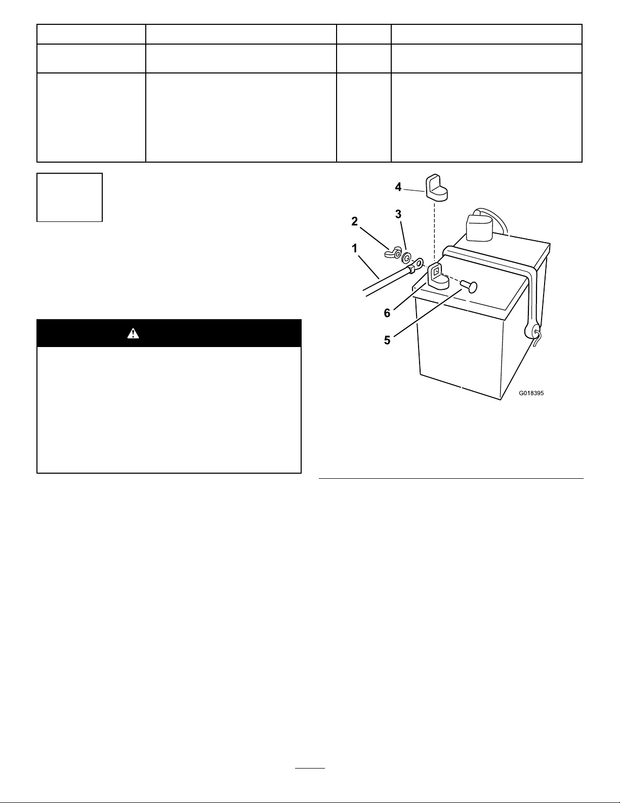
1.Locatethebatteryandnegativebatterycable.
2.Removetheplasticcapfromthenegative
batterypost.
3.Removethefastenersonthenegativebattery
cable,andusethemtosecurethenegative
batterycabletothenegativebatterypost(Figure
1).
Figure1
1.Negativebatterycable4.Negativebatterypostcap
2.Wingnut
3.Washer6.Negativebatterypost
5.Carriagebolt
g018395
2
Page 3
2
3
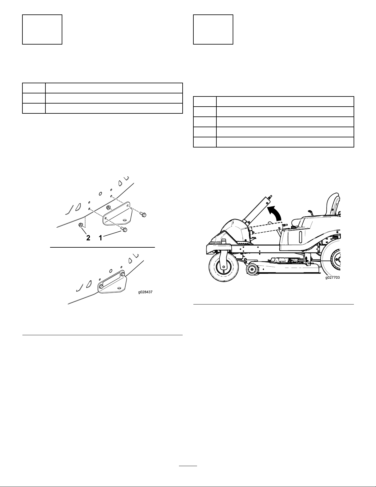
InstallingtheRearHitch
Partsneededforthisprocedure:
1Rearhitch
2
Bolt(5/16x1inch)
2
Locknut(5/16inch)
Procedure
1.Installthebrackettotheframeasshownin
Figure2.
2.Torquetheboltsbetween19.8and25.4N∙m
(175and225in-lb).
InstallingtheSteering
Wheel
Partsneededforthisprocedure:
1
Steeringwheel
1Topcover
1Locknut
1Rearcover
2
Screws
Procedure
1.Rotatethesteeringcolumnuptotheuser
position(Figure3).
Figure2
1.Bolt(2)2.Locknut(2)
g027703
Figure3
g028437
2.PositionthesteeringwheelasshowninFigure5.
3.Installthesteeringwheelandtopcovertothe
steeringcolumnwiththelocknut(Figure4).
4.Torquethelocknutbetween36.6and44.7N∙m
(27and33ft-lb).
5.Installthesteering-wheelcover.
3
Page 4

Figure4
1.Steering-wheelcover
2.Locknut
3.Steeringwheel
6.Installtherearcovertothebackofthefootrest
withthetabsatthebottominsidethefootrest
andthe2screwsinthetop(Figure5).
4.Topcover
5.Column
Note:Ensurethetabsoftherearcoverare
insidethefootrest.
4
InstallingtheSeattothe
SeatPan
MachinesShippedinaSteelCrate
Only
Partsneededforthisprocedure:
g027737
Procedure
2
Shoulderbolt(seatswithoutadetachedcushiononly)
1
Seat(seatswithoutadetachedcushiononly)
2Hexbolt
2Washer
1
Seatpan
1
Seatassembly(seatswithadetachedcushiononly)
1
Bottomcushion(seatswithadetachedcushiononly)
2
Flange-hexbolt(seatswithadetachedcushiononly)
1.Backcover
Figure5
1.Iftheseatdoesnothaveadetachedcushion,
installtheseattotheseatpanusing2shoulder
bolts,2hexbolts,and2washers.
g213714
Figure6
1.Shoulderbolt(2)2.Hexboltandwasher(2)
2.Iftheseatdoeshaveadetachedcushion,
g027887
2.Screws
continueasfollows:
A.Installthebottomcushiontotheseat
assemblyusing2ange-hexbolts(Figure
7).
4
Page 5

B.Placetheseatontotheseatpan,aligning
theattachedseatboltswiththefront
keyholes,andslidetheseatback.
C.Securetheseattotheseatpanusing2hex
boltsand2washers(Figure7).
5
InstallingtheSeat
Assembly
Partsneededforthisprocedure:
1
Seatassembly
1
Seatrod
2Hairpincotters
2
Spacers(certainmodelsonly)
Procedure
1.Installtheseatassemblytotheframewith
theseatrod,2hairpincotters,and2spacers
(certainmodelsonly)asshowninFigure8.
1.Flange-hexbolt(2)
2.Bolt(5/16x1inch)and
washer(2)
3.Seatassembly
Figure7
4.Bottomcushion
5.Seatpan
6.Frontkeyhole
g213797
g027723
Figure8
1.Seatassembly
2.Spacers4.Seatrodwithhairpincotter
2.Connecttheseatswitch(Figure9).
3.Hairpincotter
installed
5
Page 6

g027695
Figure9
g028383
1 2
3.Routethewireharnesstotherightsideofthe
machineandpushtheplasticconnectorintothe
seatframehole(Figure10).
6
InstallingtheGrass
Deector
Partsneededforthisprocedure:
1
Grassdeector(ifnotinstalled)
Procedure
g027695
Ifthegrassdeectorisnotinstalled,removeitfrom
thepackagingandinstallitontothemowerdeck.
RefertoyourOperator’sManualforthecorrect
proceduretoinstallthegrassdeector.
7
CheckingtheMower
1.Plasticconnectorinseat
framehole
Adjustment
NoPartsRequired
Procedure
Adjusttheside-to-sidelevelandthefront-to-rearblade
slope.UsetherelevantproceduresintheOperator's
Manualtoverifythatthedeckislevel,andmakeany
adjustmentsasnecessary.RefertotheOperator's
Manualformoreinformation.
g028383
Figure10
2.Wireharness
6
Page 7

8
CompletingtheSetup
Partsneededforthisprocedure:
1Ignitionkey
1
Hosecoupling(notincludedwithCEmodels)
1
Operator'sManual
1
EngineOwner’sManual(non-Toroengines)
1
KeyChoice
Procedure
CheckingtheTirePressure
Checkthefrontandreartiresforproperination;
refertoCheckingtheTirePressureintheOperator's
Manualfortherecommendedinationpressure.
CheckingtheSide-DischargeChute
Removethepackingrestraintholdingtheside
dischargechuteupandlowerthechuteintoplace.
®
key(blue)
CheckingtheEngine-OilLevel
Beforeyoustarttheengineandusethemachine,
checktheoillevelintheenginecrankcase;referto
CheckingtheOilLevelintheOperator'sManual.
Keepallthefollowingitemswiththemachine:
•Ignitionkey
•KeyChoicekey(blue)
•Hosecoupling(notincludedinCEmodels)
•Operator'sManual
•EngineOwner’sManual(non-Toroengines)
7
Page 8

 Loading...