

Page 1

TimeCutter
ModelNo.SWTimeCutterModels
Setup
LooseParts
Usethechartbelowtoverifythatallpartshavebeenshipped.
®
SWRidingMower
FormNo.3393-925RevC
SetupInstructions
ProcedureDescription
1
2
3
4
5
6
7
Nopartsrequired
Rearhitch1
Bolt(5/16x1inch)
Locknut(5/16inch)
Steeringwheel
Topcover1
Locknut1
Rearcover1
Screws
Seatassembly
Seatrod
Hairpincotterpins2
Spacers(certainmodelsonly)
Grassdeector(ifnotinstalled)
Nopartsrequired
Ignitionkey1
Hosecoupling(notincludedwithCE
models)
Operator'sManual
EngineOwner’sManual(non-T oro
engines)
KeyChoice®key(blue)
Qty.
Use
–
2
2
1
2
1
1
2
1
–
1
1
1
1
Connectthebattery.
Installtherearhitch.
Installthesteeringwheel.
Installtheseatassembly .
Installthegrassdeector.
Checkthemoweradjustment.
Completethesetup.
Note:Determinetheleftandrightsidesofthemachinefromthenormaloperatingposition.
©2016—TheToro®Company
8111LyndaleAvenueSouth
Bloomington,MN55420
Registeratwww .T oro.com.
OriginalInstructions(EN)
PrintedintheUSA
AllRightsReserved
*3393-925*C
Page 2
1
G018395
2
1
4
3
6
5
2
ConnectingtheBattery
NoPartsRequired
Procedure
WARNING
CALIFORNIA
Proposition65Warning
Batteryposts,terminals,andrelated
accessoriescontainleadandleadcompounds,
chemicalsknowntotheStateofCalifornia
tocausecancerandreproductiveharm.
Washhandsafterhandling .
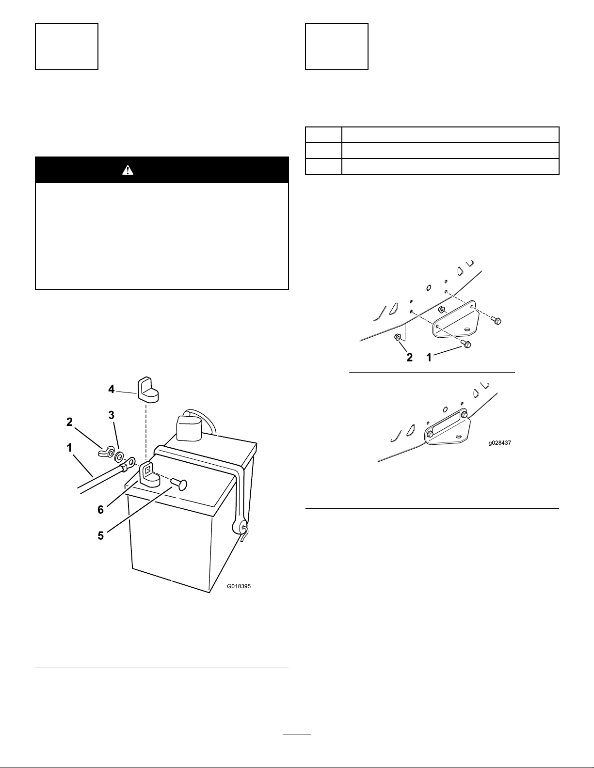
1.Locatethebatteryandnegativebatterycable.
2.Removetheplasticcapfromthenegativebatterypost.
3.Removethefastenersonthenegativebatterycable,
andusethemtosecurethenegativebatterycableto
thenegativebatterypost(Figure1).
InstallingtheRearHitch
Partsneededforthisprocedure:
1Rearhitch
2
Bolt(5/16x1inch)
2
Locknut(5/16inch)
Procedure
1.InstallthebrackettotheframeasshowninFigure2.
2.Torquetheboltsbetween19.8and25.4N-m(175and
225in-lb).
g028437
Figure2
1.Bolts2.Locknuts
Figure1
1.Negativebatterycable4.Negativebatterypostcap
2.Wingnut
3.Washer6.Negativebatterypost
5.Carriagebolt
g018395
2
Page 3
3
InstallingtheSteeringWheel
Partsneededforthisprocedure:
1
Steeringwheel
1Topcover
1Locknut
1Rearcover
2
Screws
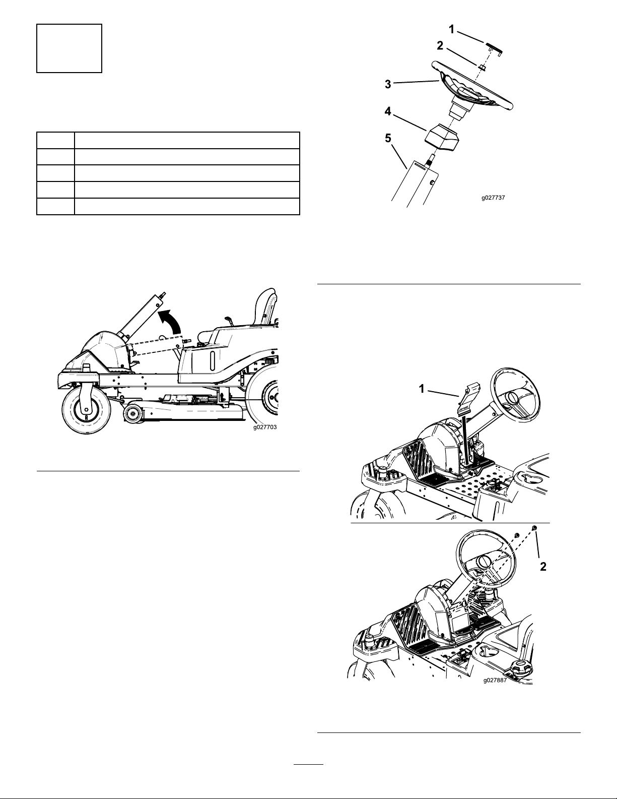
g027737
Figure4
Procedure
1.Rotatethesteeringcolumnuptotheuserposition
(Figure3).
Figure3
2.PositionthesteeringwheelasshowninFigure5.
3.Installthesteeringwheelandtopcovertothesteering
columnwiththelocknut(Figure4).
1.Steering-wheelcover
2.Locknut
3.Steeringwheel
4.Topcover
5.Column
6.Installtherearcovertothebackofthefootrestwith
thetabsatthebottominsidethefootrestandthe2
screwsinthetop(Figure5).
Note:Ensurethetabsoftherearcoverareinsidethe
footrest.
g027703
4.Torquethelocknutbetween36.6and44.7N-m(27
and33ft-lb).
5.Installthesteering-wheelcover.
g027887
Figure5
1.Backcover
3
2.Screws
Page 4

4
g027695
g028383
1 2
InstallingtheSeatAssembly
Partsneededforthisprocedure:
1
Seatassembly
1
Seatrod
2Hairpincotterpins
2
Spacers(certainmodelsonly)
Procedure
1.Installtheseatassemblytotheframewiththeseatrod,
2hairpincotterpins,and2spacers(certainmodels
only)asshowninFigure6.
2.Connecttheseatswitch(Figure7).
g027695
Figure7
3.Routethewireharnesstotherightsideofthemachine
andpushtheplasticconnectorintotheseatframehole
(Figure8).
Figure6
1.Seatassembly
2.Spacers4.Seatrodwithhairpincotter
3.Hairpincotter
installed
g027723
g028383
Figure8
1.Plasticconnectorinseat
framehole
4
2.Wireharness
Page 5

5
7
InstallingtheGrassDeector
Partsneededforthisprocedure:
1
Grassdeector(ifnotinstalled)
Procedure
Ifthegrassdeectorisnotinstalled,removeitfromthe
packagingandinstallitontothemowerdeck.Refertoyour
Operator’sManualforthecorrectproceduretoinstallthegrass
deector.
6
CheckingtheMower
Adjustment
NoPartsRequired
CompletingtheSetup
Partsneededforthisprocedure:
1Ignitionkey
1
Hosecoupling(notincludedwithCEmodels)
1
Operator'sManual
1
EngineOwner’sManual(non-T oroengines)
1
KeyChoice
Procedure
CheckingtheTirePressure
Checkthefrontandreartiresforproperination;referto
CheckingtheTirePressureintheOperator'sManualforthe
recommendedinationpressure.
CheckingtheSide-DischargeChute
Removethepackingrestraintholdingthesidedischargechute
upandlowerthechuteintoplace.
CheckingtheEngine-OilLevel
®
key(blue)
Procedure
Adjusttheside-to-sidelevelandthefront-to-rearbladeslope.
UsetherelevantproceduresintheOperator'sManualtoverify
thatthedeckislevel,andmakeanyadjustmentsasnecessary.
RefertotheOperator'sManualformoreinformation.
Beforeyoustarttheengineandusethemachine,checkthe
oillevelintheenginecrankcase;refertoCheckingtheOil
LevelintheOperator'sManual.
Keepallthefollowingitemswiththemachine:
•Ignitionkey
•KeyChoicekey(blue)
•Hosecoupling(notincludedinCEmodels)
•Operator'sManual
•EngineOwner’sManual(non-Toroengines)
5
Page 6

Notes:
Page 7

Notes:
Page 8

 Loading...