

Page 1

FormNo.3417-368RevA
TimeCutter
®
ZS4200TorZS5000
RidingMower
ModelNo.74661—SerialNo.400900000andUp
ModelNo.74667—SerialNo.400000000andUp
Registeratwww.T oro.com.
OriginalInstructions(EN)
*3417-368*A
Page 2
ThisproductcomplieswithallrelevantEuropean
directives;fordetails,pleaseseetheseparateproduct
specicDeclarationofConformity(DOC)sheet.
GrossHorsepower
Thegrossornethorsepowerofthisenginewas
laboratoryratedbytheenginemanufacturerin
accordancewiththeSocietyofAutomotiveEngineers
(SAE)J1940orJ2723.Asconguredtomeet
safety,emission,andoperatingrequirements,the
actualenginetorqueonthisclassofmowerwillbe
signicantlylower.
Gotowww.Toro.comtoviewspecicationsonyour
mowermodel.
Important:IfyouareusingamachinewithaToro
engineabove1500m(5,000ft)foracontinuous
period,ensurethattheHighAltitudeKithasbeen
installedsothattheenginemeetsCARB/EPA
emissionregulations.TheHighAltitudeKit
increasesengineperformancewhilepreventing
spark-plugfouling,hardstarting,andincreased
emissions.Onceyouhaveinstalledthekit,attach
thehigh-altitudelabelnexttotheserialdecalon
themachine.ContactanyAuthorizedToroService
DealertoobtaintheproperHighAltitudeKitand
high-altitudelabelforyourmachine.Tolocate
adealerconvenienttoyou,accessourwebsite
atwww.T oro.comorcontactourT oroCustomer
CareDepartmentatthenumber(s)listedinyour
EmissionControlWarrantyStatement.
Removethekitfromtheengineandrestorethe
enginetoitsoriginalfactorycongurationwhen
runningtheengineunder1500m(5,000ft).Do
notoperateanenginethathasbeenconverted
forhigh-altitudeuseatloweraltitudes;otherwise,
youcouldoverheatanddamagetheengine.
Ifyouareunsurewhetherornotyourmachinehas
beenconvertedforhigh-altitudeuse,lookforthe
followinglabel(Figure3).
Introduction
Thismachineisaride-on,rotary-bladeintendedtobe
usedbyhomeownersinresidentialapplications.Itis
primarilydesignedforcuttinggrassonwell-maintained
lawns.Itisnotdesignedforcuttingbrush,mowing
grassandothergrowthalongsidehighways,orfor
agriculturaluses.
Readthisinformationcarefullytolearnhowtooperate
andmaintainyourproductproperlyandtoavoid
injuryandproductdamage.Youareresponsiblefor
operatingtheproductproperlyandsafely .
YoumaycontactT orodirectlyatwww.Toro.com
forproductsafetyandoperationtrainingmaterials,
accessoryinformation,helpndingadealer,orto
registeryourproduct.
FortheOperator’sManual,thecompletewarranty
details,ortoregisteryourproduct,usetheQR
codeorvisitwww.Toro.com.Y oumayalsocallus
at1-888-384-9939torequestawrittencopyofthe
productwarranty.
Wheneveryouneedservice,genuineToroparts,or
additionalinformation,contactanAuthorizedService
DealerorToroCustomerServiceandhavethemodel
andserialnumbersofyourproductready.Figure1
identiesthelocationofthemodelandserialnumbers
ontheproduct.Writethenumbersinthespace
provided.
©2017—TheToro®Company
8111LyndaleAvenueSouth
Bloomington,MN55420
Figure3
g188142
Figure1
Undertheseat
decal127-9363
1.Modelandserial-numberplate
Writetheproductmodelandserialnumbersinthe
spacebelow:
ModelNo.
SerialNo.
Contactusatwww.Toro.com.
2
PrintedintheUSA
AllRightsReserved
Page 3

Thismanualidentiespotentialhazardsandhas
safetymessagesidentiedbythesafety-alertsymbol
(Figure2),whichsignalsahazardthatmaycause
seriousinjuryordeathifyoudonotfollowthe
recommendedprecautions.
Figure2
Safety-alertsymbol
Thismanualuses2wordstohighlightinformation.
Importantcallsattentiontospecialmechanical
informationandNoteemphasizesgeneralinformation
worthyofspecialattention.
Contents
Safety.......................................................................4
GeneralSafety...................................................4
SlopeIndicator...................................................5
SafetyandInstructionalDecals..........................6
ProductOverview...................................................14
g000502
Controls...........................................................14
BeforeOperation.................................................16
BeforeOperationSafety...................................16
AddingFuel......................................................16
PerformingDailyMaintenance..........................17
BreakinginaNewMachine..............................17
UsingtheSafety-InterlockSystem....................18
PositioningtheSeat..........................................18
AdjustingtheMotion-ControlLevers.................19
ConvertingtoSideDischarge...........................19
DuringOperation.................................................22
DuringOperationSafety...................................22
OperatingtheMowerBlade-ControlSwitch
(PTO)............................................................24
OperatingtheThrottle.......................................25
OperatingtheChoke.........................................25
StartingtheEngine...........................................26
ShuttingOfftheEngine.....................................26
UsingtheMotion-ControlLevers.......................26
DrivingtheMachine..........................................26
UsingtheSideDischarge.................................29
AdjustingtheHeightofCut...............................29
AdjustingtheAnti-ScalpRollers........................30
OperatingTips.................................................31
AfterOperation....................................................32
AfterOperationSafety......................................32
PushingtheMachinebyHand..........................32
TransportingtheMachine.................................33
Maintenance...........................................................35
RecommendedMaintenanceSchedule(s)...........35
Pre-MaintenanceProcedures..............................36
MaintenanceSafety..........................................36
RaisingtheSeat...............................................36
ReleasingtheMower-DeckCurtain..................36
Lubrication..........................................................37
GreasingtheBearings......................................37
EngineMaintenance...........................................37
EngineSafety...................................................37
ServicingtheAirCleaner..................................37
ServicingtheEngineOil....................................39
ServicingtheSparkPlug...................................41
CleaningtheCoolingSystem............................42
FuelSystemMaintenance...................................43
ReplacingtheIn-LineFuelFilter.......................43
ElectricalSystemMaintenance...........................44
ElectricalSystemSafety...................................44
ServicingtheBattery.........................................44
ServicingtheFuses..........................................45
DriveSystemMaintenance..................................46
CheckingtheTirePressure...............................46
ReleasingtheElectricBrake.............................46
3
Page 4

BeltMaintenance................................................47
ReplacingtheMower-DeckBelt........................47
MowerMaintenance.............................................48
ServicingtheCuttingBlades.............................48
LevelingtheMowerDeck..................................51
RemovingtheMowerDeck...............................53
InstallingtheMowerDeck.................................54
ReplacingtheGrassDeector..........................54
Cleaning..............................................................55
WashingtheUndersideoftheMower
Deck..............................................................55
DisposingofWaste...........................................55
Storage...................................................................56
StorageSafety..................................................56
CleaningandStorage.......................................56
StoringtheBattery............................................57
Troubleshooting......................................................58
Schematics.............................................................60
Safety
Thismachinehasbeendesignedinaccordancewith
ENISO5395:2013.
GeneralSafety
Thisproductiscapableofamputatinghandsand
feetandofthrowingobjects.Alwaysfollowallsafety
instructionstoavoidseriouspersonalinjury.
Usingthisproductforpurposesotherthanitsintended
usecouldprovedangeroustoyouandbystanders.
•Donotoperatethemachineneardrop-offs,
ditches,embankments,water,orotherhazards,or
onslopesgreaterthan15degrees.
•Readandunderstandthecontentsofthis
Operator’sManualbeforestartingtheengine.
•Donotputyourhandsorfeetnearmoving
componentsofthemachine.
•Donotoperatethemachinewithoutallguards
andothersafetyprotectivedevicesinplaceand
workingonthemachine.
•Keepchildrenandbystandersoutoftheoperating
area.Neverallowchildrentooperatethemachine.
•Stopthemachineandshutofftheenginebefore
servicing,fueling,oruncloggingthemachine.
Improperlyusingormaintainingthismachinecan
resultininjury .T oreducethepotentialforinjury,
complywiththesesafetyinstructionsandalwayspay
attentiontothesafety-alertsymbol,whichmeans
Caution,Warning,orDanger—personalsafety
instruction.Failuretocomplywiththeseinstructions
mayresultinpersonalinjuryordeath.
Youcanndadditionalsafetyinformationwhere
neededthroughoutthismanual.
4
Page 5
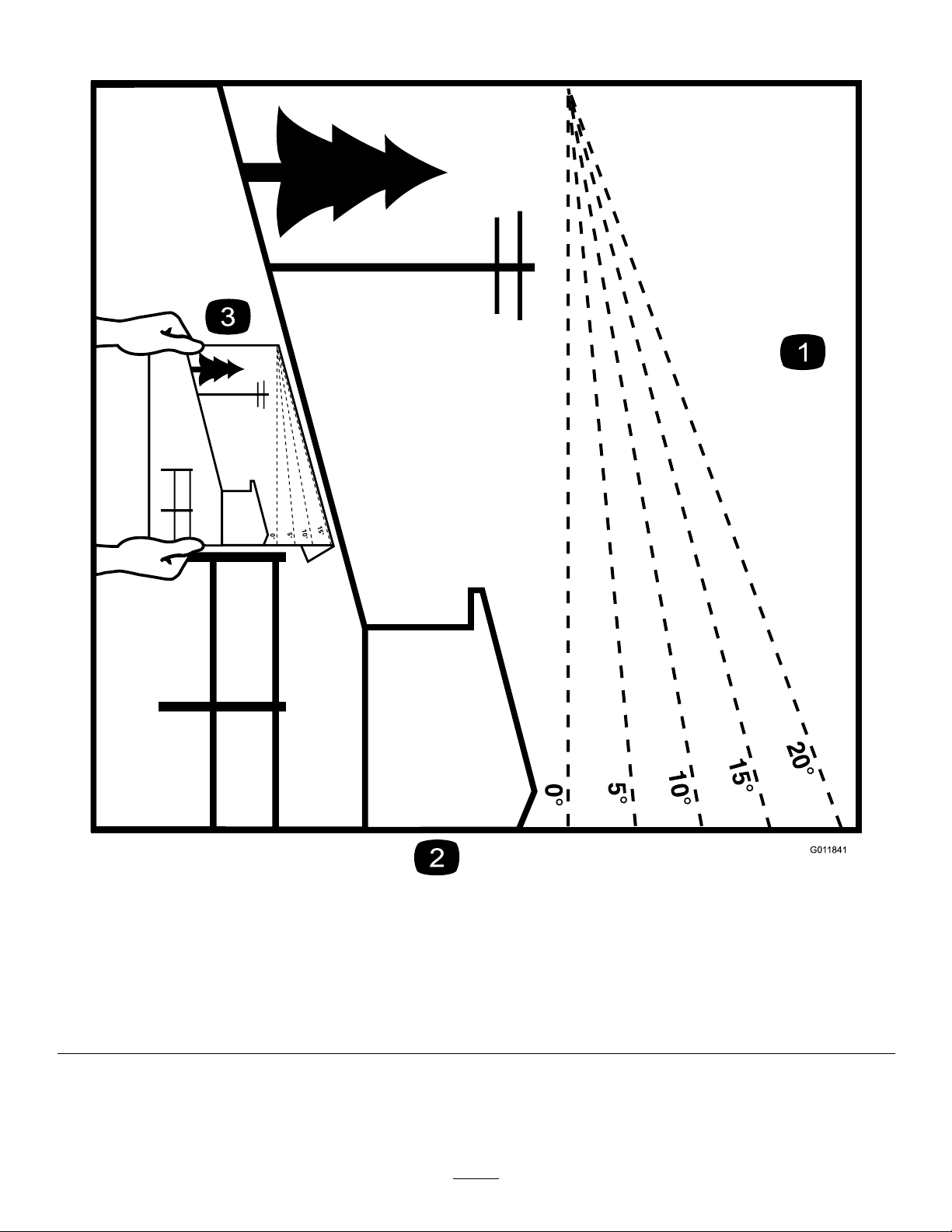
SlopeIndicator
Figure4
Thispagemaybecopiedforpersonaluse.
1.Themaximumslopeyoucanoperatethemachineonis15degrees.Usetheslopecharttodeterminethedegreeofslopeof
hillsbeforeoperating.Donotoperatethismachineonaslopegreaterthan15degrees.Foldalongtheappropriateline
tomatchtherecommendedslope.
2.Alignthisedgewithaverticalsurface,atree,building,fencepole,etc.
3.Exampleofhowtocompareslopewithfoldededge
5
g011841
Page 6
SafetyandInstructionalDecals
Safetydecalsandinstructionsareeasilyvisibletotheoperatorandarelocatednearanyarea
ofpotentialdanger.Replaceanydecalthatisdamagedormissing.
BatterySymbols
Someorallofthesesymbolsareonyourbattery .
decalbatterysymbols
1.Explosionhazard
2.Nore,opename,or
smoking
3.Causticliquid/chemical
burnhazard
4.Weareyeprotection.9.Flusheyesimmediately
5.ReadtheOperator's
Manual.
6.Keepbystandersasafe
distanceawayfromthe
battery.
7.Weareyeprotection;
explosivegasescan
causeblindnessandother
injuries.
8.Batteryacidcancause
blindnessorsevereburns.
withwaterandgetmedical
helpfast.
10.Containslead;donot
discard
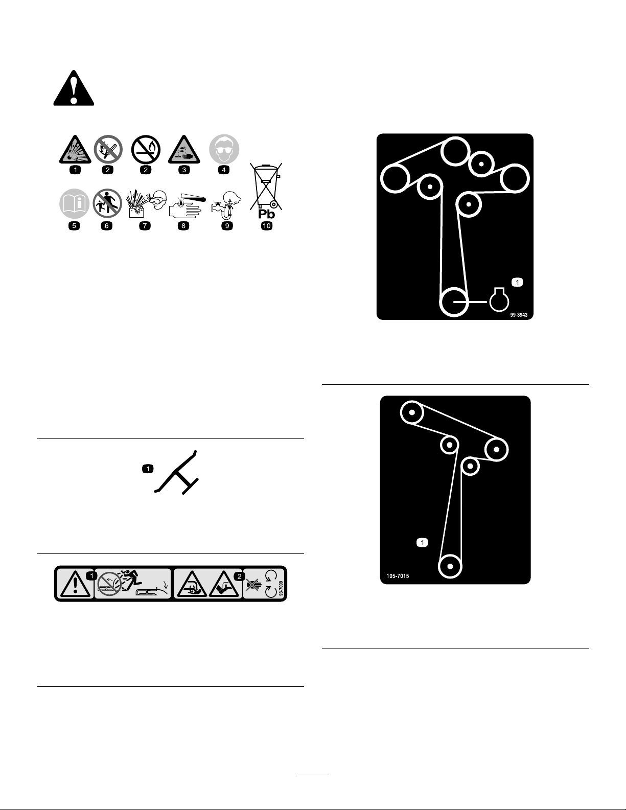
Manufacturer'sMark
1.Indicatesthebladeisidentiedasapartfromtheoriginal
machinemanufacturer.
decal99-3943
99-3943
ForModelswith127cm(50inch)Decks
1.Engine
decaloemmarkt
93-7009
1.Warning—donotoperatethemowerwiththedeectorup
orremoved;keepthedeectorinplace.
2.Cutting/dismembermenthazardofhandorfoot,mower
blade—stayawayfrommovingparts.
decal105-7015
decal93-7009
1.Beltrouting
ForModelswith107cm(42-inch)Decks
105-7015
6
Page 7
106-8717
1.Readtheinstructionsbeforeservicingorperforming
maintenance.
2.Checktirepressureevery25operatinghours.
3.Greaseevery25operatinghours.
4.Engine
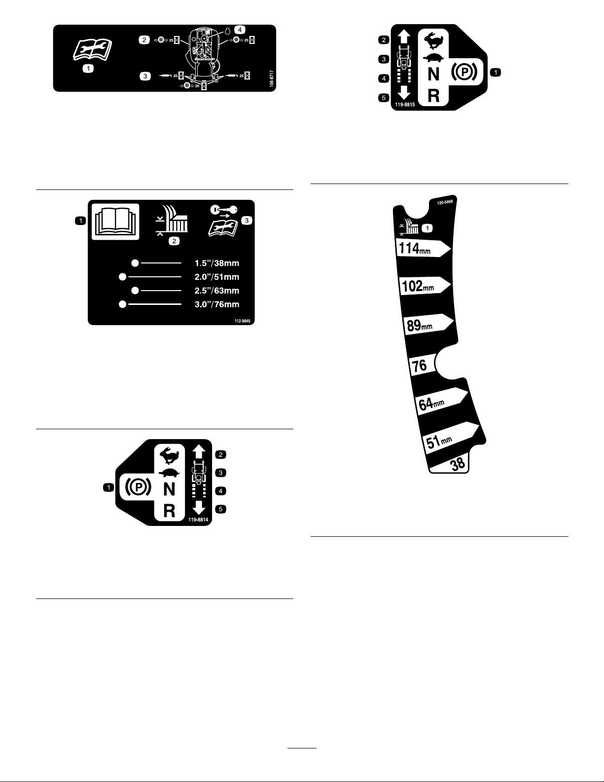
112-9840
ForModelswith127cm(50inch)Decks
decal106-8717
decal119-8815
119-8815
1.Parkingposition4.Neutral
2.Fast5.Reverse
3.Slow
decal112-9840
1.ReadtheOperator's
Manual.
2.Heightofcut
119-8814
1.Parkingposition4.Neutral
2.Fast5.Reverse
3.Slow
3.Removethekeyandread
theinstructionsbefore
servicingorperforming
maintenance.
decal120-5469
120-5469
ForModelswith107cm(42inch)Decks
1.Heightofcut
decal119-8814
7
Page 8
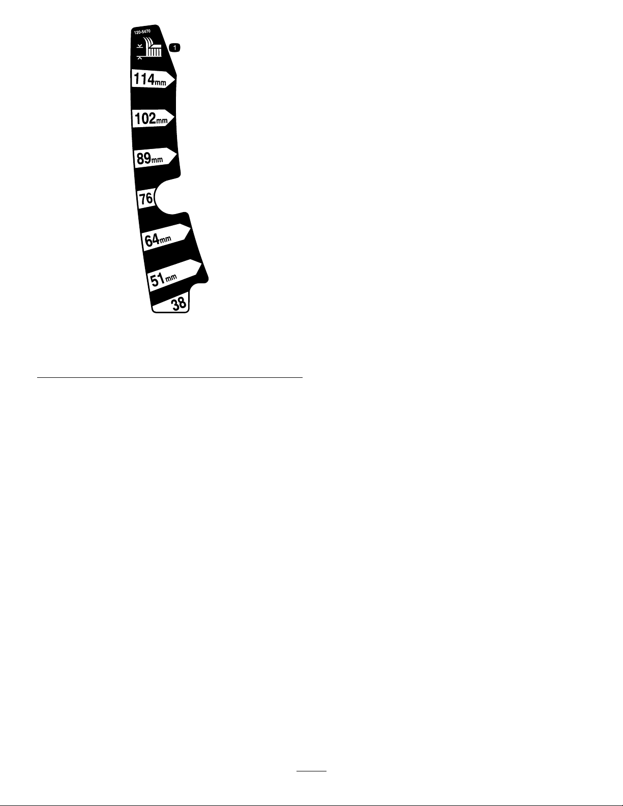
ForModelswith127cm(50inch)Decks
1.Heightofcut
decal120-5470
120-5470
8
Page 9
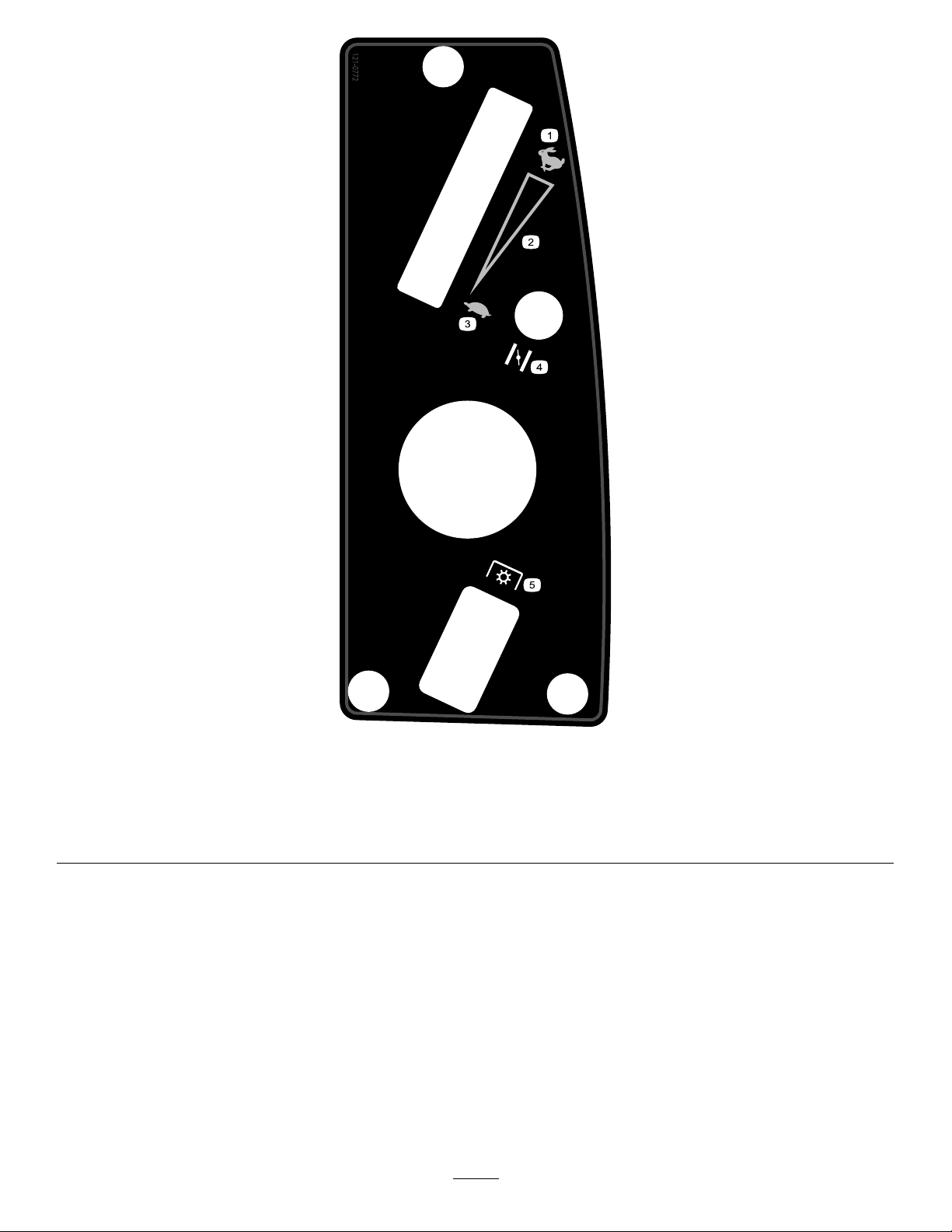
121-0772
ForModelswith107cm(42inch)Decks
decal121-0772
1.Fast
4.Choke
2.Continuous-variablesetting5.Powertakeoff(PTO),blade-controlswitch
3.Slow
9
Page 10
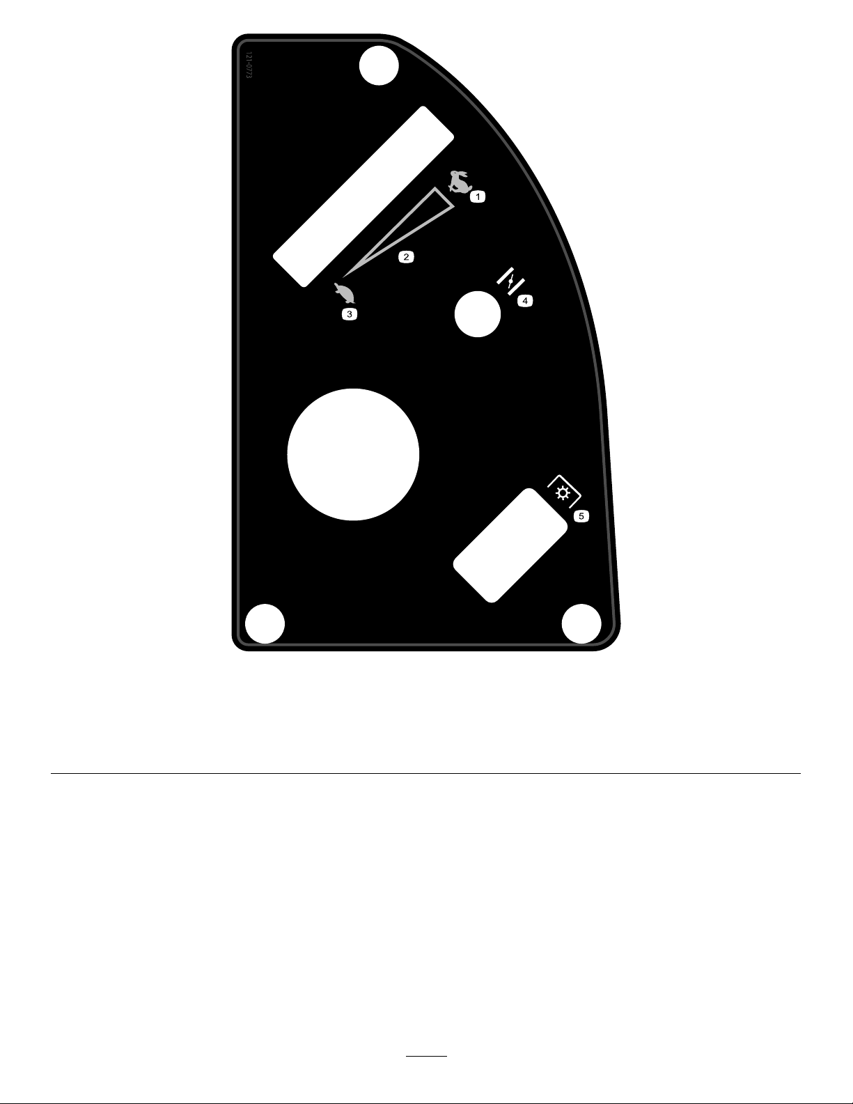
121-0773
ForModelswith127cm(50inch)Decks
decal121-0773
1.Fast
4.Choke
2.Continuous-variablesetting5.Powertakeoff(PTO),blade-controlswitch
3.Slow
10
Page 11

decal121-2989b
131-3948
121-2989
1.Bypassleverpositionfor
pushingthemachine
1.Oildrain
2.Bypassleverpositionfor
operatingthemachine
decal131-1097
131-1097
decal131-3948
131-3948
1.Slow
2.Towing
3.Fast
11
Page 12
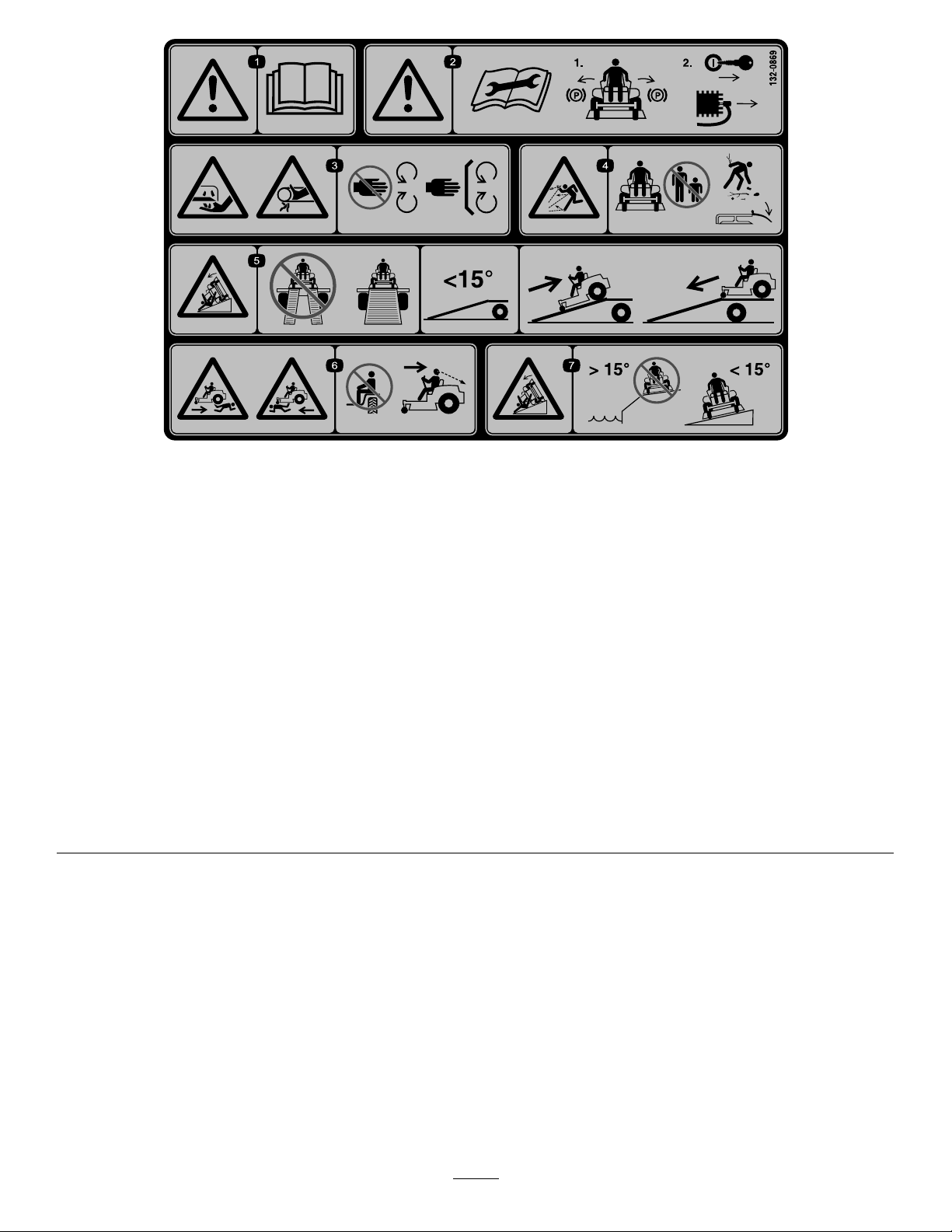
132-0869
Note:Thismachinecomplieswiththeindustrystandardstabilitytestinthestaticlateralandlongitudinaltestswiththemaximum
recommendedslopeindicatedonthedecal.Theoperatormustreviewtheinstructionsforoperatingthemachineonslopesinthe
Operator’sManualandreviewtheconditionsinwhichthemachineisbeingoperatedtodeterminewhetherthemachinecanbeoperated
intheconditionsonthatdayandatthatsite.Changesintheterraincanresultinachangeinslopeoperationforthemachine.Ifpossible,
keepthecuttingunitsloweredtothegroundwhileoperatingthemachineonslopes.Raisingthecuttingunitswhileoperatingon
slopescancausethemachinetobecomeunstable.
decal132-0869
1.Warning—readthe
Operator'sManual.
2.Warning—beforeservicing,
engagetheparkingbrake,
removethekeyandthe
sparkplugconnection.
3.Cuttinghazardofhand,
mowerblade;pinching
hazardofhand,belt—keep
handsandfeetawayfrom
movingparts;keepall
guardsandshieldsinplace.
4.Thrownobject
hazard—keepbystanders
awayfromthemachine;
removedebrisfromthe
areabeforemowing;keep
thedeectorshielddown.
5.Ramptipping
hazard—whenloading
ontoatrailer,donotuse
dualramps;useonlya
singlerampwideenough
forthemachineandthat
hasaninclinelessthan
15degrees;backupthe
ramp(inreverse)anddrive
forwardofftheramp.
6.Bodilyharmhazard—no
riders;lookbehindyou
whenmowinginreverse.
7.Tippinghazardon
slopes—donotuseon
slopesnearopenwater;do
notuseonslopesgreater
than15degrees.
12
Page 13
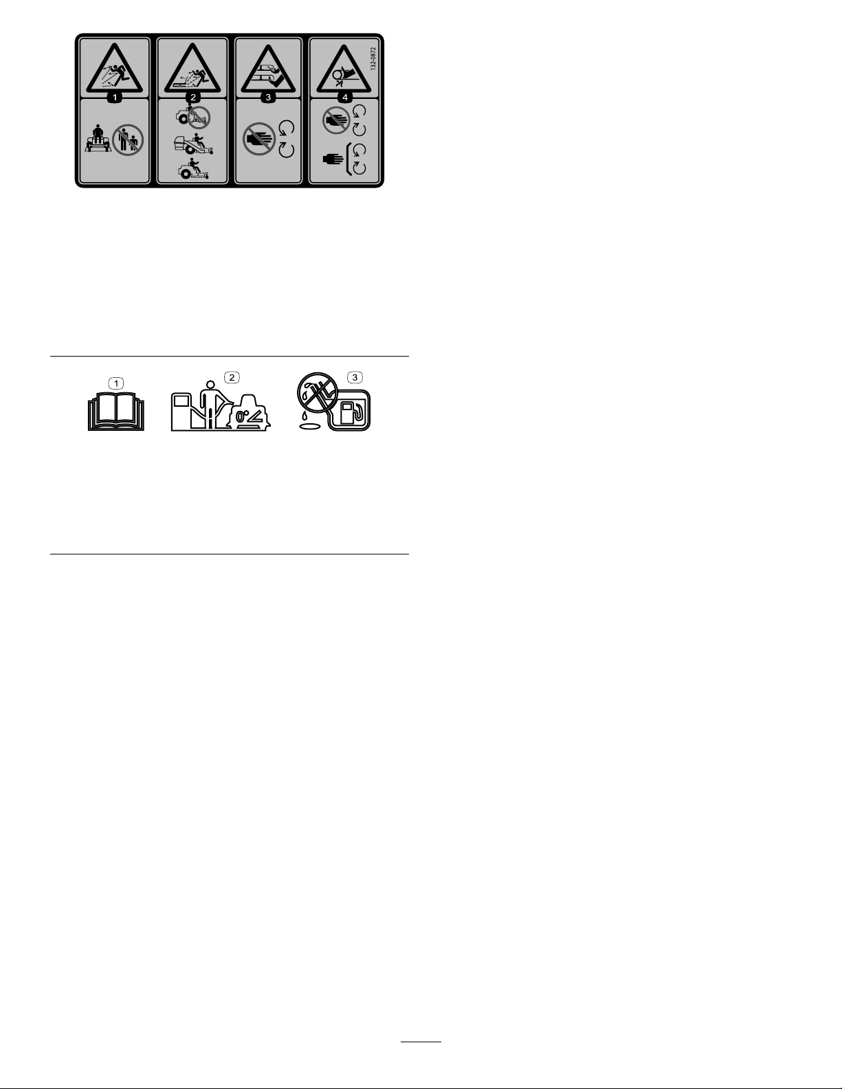
decal132-0872
132-0872
1.Thrownobject
hazard—keepbystanders
awayfromthemachine.
2.Thrownobjecthazard,
raisedbafe—donot
operatethemachinewith
anopendeck;usea
baggerorabafe.
1.ReadtheOperator’s
Manual.
2.Parkthemachineona
levelsurfacewhenlling
thefueltank.
3.Severinghazardofhand
orfoot—keepawayfrom
movingparts.
4.Entanglement
hazard—keepaway
frommovingparts;keep
allguardsandshieldsin
place.
decal138-2456
138-2456
3.Donotoverllthefuel
tank.
13
Page 14
ProductOverview
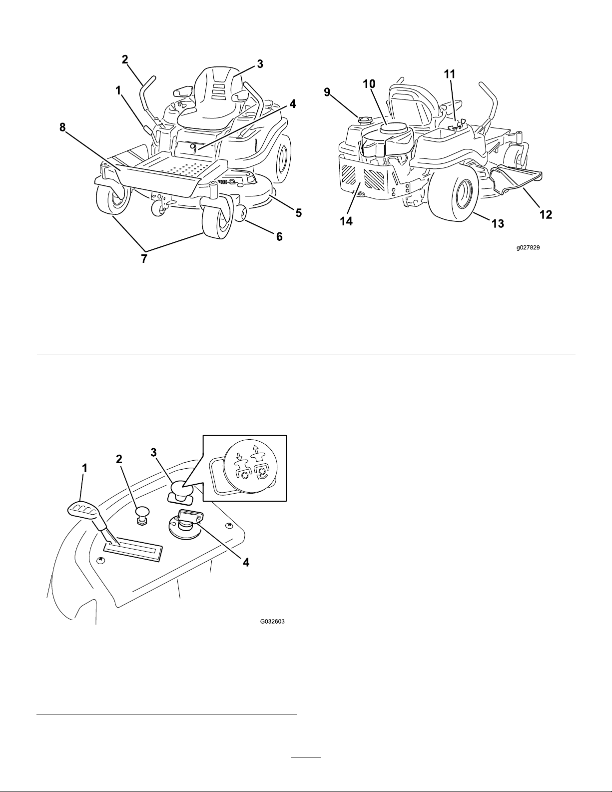
g027829
Figure5
1.Height-of-cutlever
2.Motion-controllevers6.Anti-scalproller10.Engine14.Engineguard
3.Operatorseat
4.SmartSpeed™lever
Controls
Becomefamiliarwithallthecontrolsbeforeyoustart
theengineandoperatethemachine.
5.Mowerdeck9.Fuel-tankcap13.Reardrivewheel
7.Frontcasterwheels
8.Footrest
11.Controlpanel
12.Deector
KeySwitch
Thekeyswitch,usedtostartandshutofftheengine,
has3positions:OFF,RUN,andST ART.Referto
StartingtheEngine(page26).
ThrottleControl
Thethrottlecontrolstheenginespeed,andithasa
continuous-variablesettingfromtheSLOWtoFAST
position(Figure6).
ChokeControl
Usethechokecontroltostartacoldengine.
Figure6
Controlpanel
1.Throttle3.Blade-controlswitch
2.Choke
(powertakeoff)
4.Ignitionswitch
Blade-ControlSwitch(Power
Takeoff)
g032603
Theblade-controlswitch,representedbya
power-takeoff(PTO)symbol,engagesand
disengagespowertothemowerblades(Figure6).
14
Page 15
Motion-ControlLevers
Height-of-CutLever
Usethemotion-controlleverstodrivethemachine
forward,reverse,andturneitherdirection(Figure5).
ParkPosition
Movethemotion-controlleversoutwardfromthe
centertothePARKpositionwhenexitingthemachine
(Figure27).Alwayspositionthemotion-controllevers
intothePARKpositionwhenyoustopthemachineor
leaveitunattended.
SmartSpeed™ControlSystem
Lever
TheSmartSpeed™Control-Systemlever,located
belowtheoperatingposition,givesyouachoiceto
drivethemachineat3speedranges—trim,tow,and
mow(Figure30).
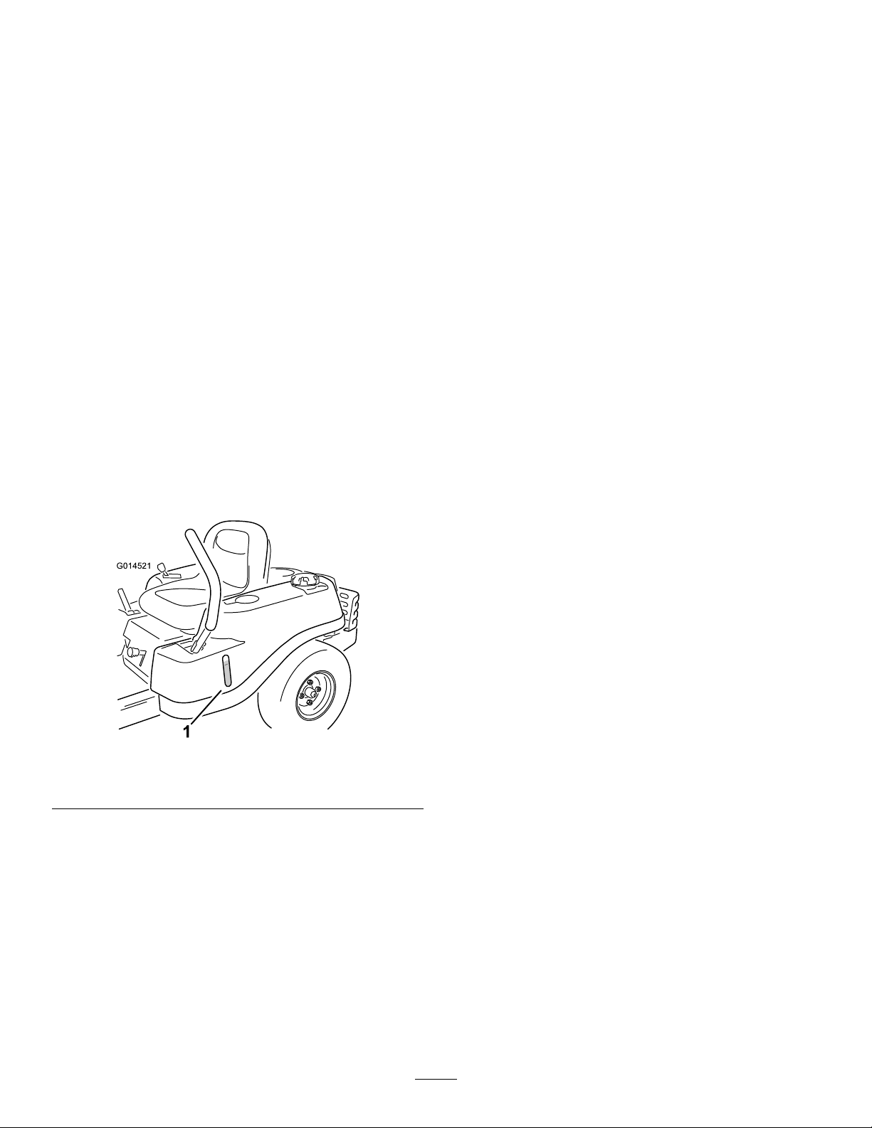
Fuel-PresenceWindow
Youcanusethefuelwindow,locatedontheleftside
ofthemachine,toverifythepresenceoffuelinthe
tank(Figure7).
Usetheheight-of-cutlevertolowerandraisethedeck
fromtheseatedposition.Movingtheleverup(toward
you)raisesthedeckfromthegroundandmovingthe
leverdown(awayfromyou)lowersthedecktoward
theground.Adjusttheheight-of-cutonlywhilethe
machineisnotmoving(Figure31).
Attachments/Accessories
AselectionofT oroapprovedattachmentsand
accessoriesisavailableforusewiththemachineto
enhanceandexpanditscapabilities.Contactyour
AuthorizedServiceDealerorDistributororgoto
www.T oro.comforalistofallapprovedattachments
andaccessories.
Tobestprotectyourinvestmentandmaintainoptimal
performanceofyourToroequipment,countonToro
genuineparts.Whenitcomestoreliability,Toro
deliversreplacementpartsdesignedtotheexact
engineeringspecicationofourequipment.Forpeace
ofmind,insistonT orogenuineparts.
1.Fuel-presencewindow
g014521
Figure7
15
Page 16

Operation
Note:Determinetheleftandrightsidesofthe
machinefromthenormaloperatingposition.
BeforeOperation
BeforeOperationSafety
GeneralSafety
•Neverallowchildrenoruntrainedpeopleto
operateorservicethemachine.Localregulations
mayrestricttheageoftheoperator.Theowner
isresponsiblefortrainingalloperatorsand
mechanics.
•Becomefamiliarwiththesafeoperationofthe
equipment,operatorcontrols,andsafetysigns.
•Knowhowtostopthemachineandshutoffthe
enginequickly.
•Checkthatoperator-presencecontrols,safety
switches,andshieldsareattachedandfunctioning
properly.Donotoperatethemachineunlessthey
arefunctioningproperly.
•Beforemowing,alwaysinspectthemachineto
ensurethattheblades,bladebolts,andcutting
assembliesareingoodworkingcondition.
Replacewornordamagedbladesandboltsinsets
topreservebalance.
•Inspecttheareawhereyouwillusethemachine
andremoveallobjectsthatthemachinecould
throw.
•Evaluatetheterraintodeterminetheappropriate
equipmentandanyattachmentsoraccessories
requiredtooperatethemachineproperlyand
safely.
FuelSafety
•Toavoidpersonalinjuryorpropertydamage,use
extremecareinhandlingfuel.Fuelvaporsare
ammableandexplosive.
•Extinguishallcigarettes,cigars,pipes,andother
sourcesofignition.
•Useonlyanapprovedfuelcontainer.
•Donotremovethefuelcaporaddfueltothefuel
tankwhiletheengineisrunningorwhilehot.
•Donotrefuelthemachineindoors.
•Donotstorethemachineorfuelcontainerwhere
thereisanopename,spark,orpilotlight,such
asonawaterheateroronotherappliances.
•Donotllcontainersinsideavehicleoronatruck
ortrailerbedwithaplasticliner.Alwaysplace
containersontheground,awayfromyourvehicle
beforelling.
•Removetheequipmentfromthetruckortrailer
andrefuelitwhileitisontheground.Ifthisisnot
possible,thenrefuelfromaportablecontainer
ratherthanafuel-dispensernozzle.
•Donotoperatethemachinewithouttheentire
exhaustsysteminplaceandinproperworking
condition.
•Keepthefuel-dispensernozzleincontactwith
therimofthefueltankorcontaineropeningat
alltimesuntilfuelingiscomplete.Donotusea
nozzlelock-opendevice.
•Ifyouspillfuelonyourclothing,changeyour
clothingimmediately.Wipeupanyfuelthatspills.
•Neveroverllthefueltank.Replacethefuelcap
andtightenitsecurely.
•Storefuelinanapprovedcontainerandkeepit
outofthereachofchildren.Neverbuymorethan
a30-daysupplyoffuel.
•Donotllthefueltankcompletelyfull.Addfuelto
thefueltankuntilthelevelis6to13mm(1/4to
1/2inch)belowthebottomofthellerneck.This
emptyspaceinthetankallowsfueltoexpand.
–Avoidprolongedbreathingofvapors.
–Keepyourfaceawayfromthenozzleandfuel
tankopening.
–Avoidcontactwithskin;washoffspillswith
soapandwater.
AddingFuel
RecommendedFuel
•Forbestresults,useonlyclean,fresh(lessthan
30daysold),unleadedgasolinewithanoctane
ratingof87orhigher((R+M)/2ratingmethod).
•Ethanol:Gasolinewithupto10%ethanol
(gasohol)or15%MTBE(methyltertiarybutyl
ether)byvolumeisacceptable.Ethanoland
MTBEarenotthesame.Gasolinewith15%
ethanol(E15)byvolumeisnotapprovedforuse.
Neverusegasolinethatcontainsmorethan
10%ethanolbyvolume,suchasE15(contains
15%ethanol),E20(contains20%ethanol),orE85
(containsupto85%ethanol).Usingunapproved
gasolinemaycauseperformanceproblemsand/or
enginedamagewhichmaynotbecoveredunder
warranty.
•Donotusegasolinecontainingmethanol.
•Donotstorefueleitherinthefueltankorfuel
containersoverthewinterunlessyouuseafuel
stabilizer.
•Donotaddoiltogasoline.
16
Page 17
UsingStabilizer/Conditioner
Useafuelstabilizer/conditionerinthemachineto
providethefollowingbenets:
•Keepsfuelfreshduringstorageof90daysorless
(drainthefueltankwhenstoringthemachinefor
morethan90days)
•Cleanstheenginewhileitruns
•Eliminatesgum-likevarnishbuildupinthefuel
system,whichcauseshardstarting
Important:Donotusefueladditives
containingmethanolorethanol.
Addthecorrectamountoffuelstabilizer/conditioner
tothefuel.
Note:Afuelstabilizer/conditionerismost
effectivewhenmixedwithfreshfuel.T ominimize
thechanceofvarnishdepositsinthefuelsystem,
usefuelstabilizeratalltimes.
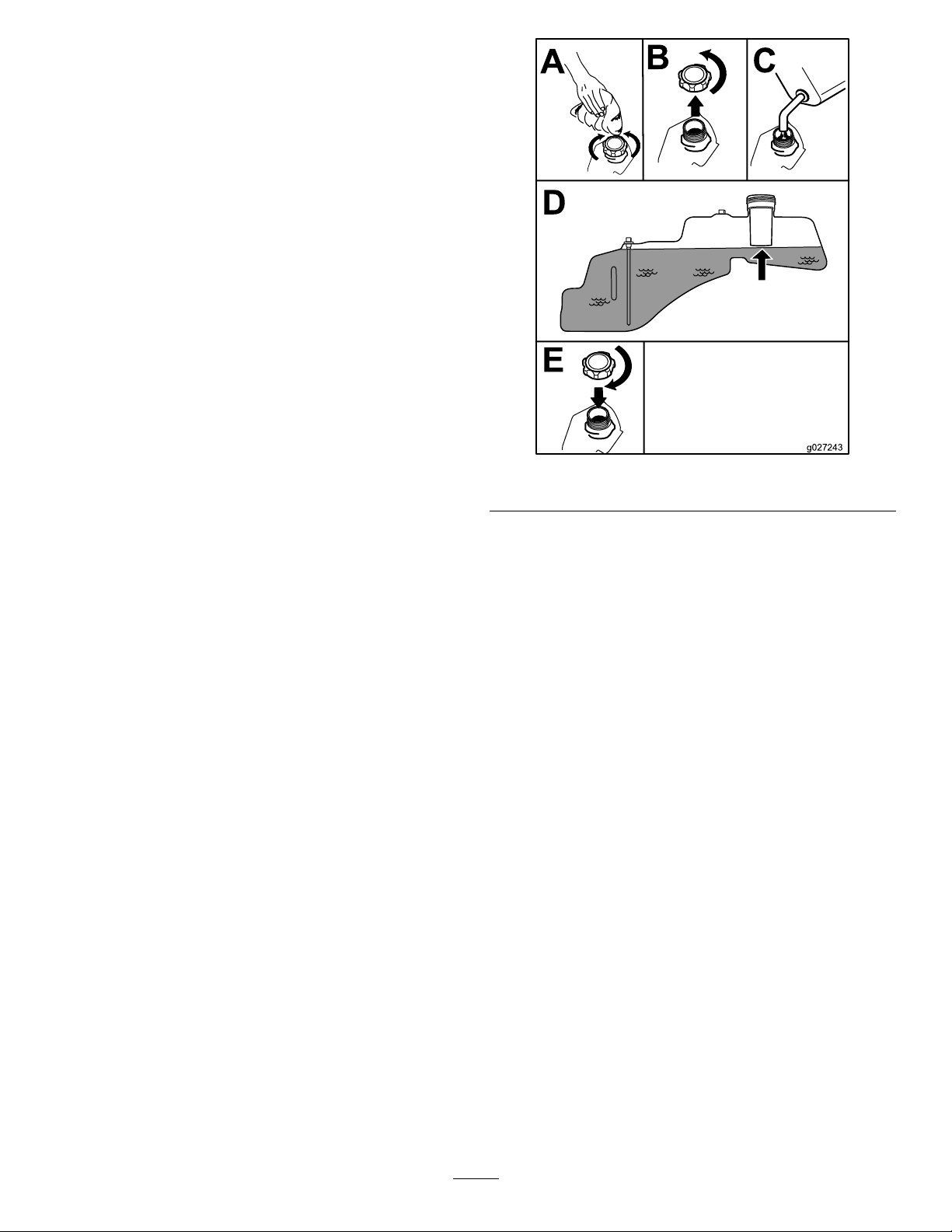
FillingtheFuelTank
g027243
Figure8
1.Parkthemachineonalevelsurface.
2.Engagetheparkingbrake.
3.Shutofftheengineandremovethekey.
4.Cleanaroundthefuel-tankcap.
5.Fillthefueltanktothebottomofthellerneck
(Figure8).
Note:Donotllthefueltankcompletelyfull.
Theemptyspaceinthetankallowsthefuelto
expand.
PerformingDaily Maintenance
Beforestartingthemachineeachday ,performthe
EachUse/DailyprocedureslistedinMaintenance
(page35).
BreakinginaNewMachine
Newenginestaketimetodevelopfullpower.Mower
decksanddrivesystemshavehigherfrictionwhen
new,placingadditionalloadontheengine.Allow
40to50hoursofbreak-intimefornewmachinesto
developfullpowerandbestperformance.
17
Page 18
UsingtheSafety-Interlock System
WARNING
Ifthesafety-interlockswitchesare
disconnectedordamaged,themachinecould
operateunexpectedly,causingpersonal
injury.
•Donottamperwiththeinterlockswitches.
•Checktheoperationoftheinterlock
switchesdailyandreplaceanydamaged
switchesbeforeoperatingthemachine.
Understandingthe Safety-InterlockSystem
Thesafety-interlocksystemisdesignedtopreventthe
enginefromstartingunless:
•Theblade-controlswitch(PTO)isdisengaged.
motion-controlleverstothecenter,unlocked
position,engagetheblade-controlswitch,and
riseslightlyfromtheseat;theengineshould
shutoff.
PositioningtheSeat
Theseatcanmoveforwardandbackward.Position
theseatwhereyouhavethebestcontrolofthe
machineandaremostcomfortable(Figure9).
•Themotion-controlleversareinthePARKposition.
Thesafety-interlocksystemalsoisdesignedtoshut
offtheenginewheneverthecontrolleversareoutof
thePARKpositionandyourisefromtheseat.
TestingtheSafety-Interlock System
Testthesafety-interlocksystembeforeyouusethe
machineeachtime.Ifthesafetysystemdoesnot
operateasdescribedbelow,haveanAuthorized
ServiceDealerrepairthesafetysystemimmediately .
1.Sitontheseat,movethemotion-controllevers
inthePARKposition,andmovetheblade-control
switchtotheONposition.Trystartingthe
engine;theengineshouldnotcrank.
2.Sitontheseatandmovetheblade-controlswitch
totheOFFposition.Moveeithermotion-control
levertothecenter,unlockedposition.Try
startingtheengine;theengineshouldnotcrank.
Repeatwiththeothermotion-controllever.
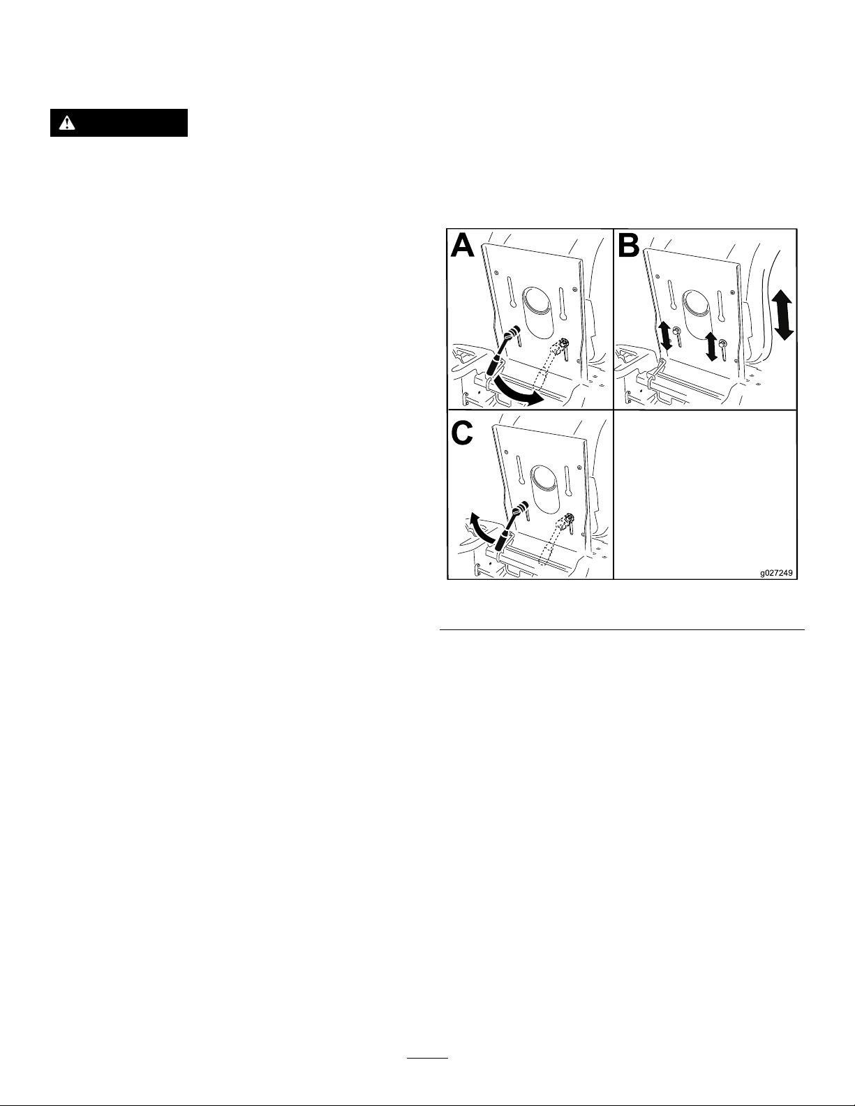
3.Sitontheseat,movetheblade-controlswitch
totheOFFposition,andlockthemotion-control
leversinthePARKposition.Starttheengine.
Whiletheengineisrunning,engagethe
blade-controlswitch,andriseslightlyfromthe
seat;theengineshouldshutoff.
g027249
Figure9
4.Sitontheseat,movetheblade-controlswitch
totheOFFposition,andlockthemotion-control
leversinthePARKposition.Starttheengine.
Whiletheengineisrunning,movethe
18
Page 19
Adjustingthe
ConvertingtoSide
Motion-ControlLevers
AdjustingtheHeight
Youcanadjustthemotion-controllevershigheror
lowerformaximumcomfort(Figure10).
Figure10
Discharge
Machineswith107cm(42-inch) MowerDecks
Themowerdeckandmowerbladesshippedwiththe
machineweredesignedforoptimummulchingand
side-dischargeperformance.
RemovingtheDischargeCoverfor
Side-Discharging
1.Parkthemachineonalevelsurface,disengage
theblade-controlswitch,andengagetheparking
brake.
2.Shutofftheengine,removethekey,andwait
forallmovingpartstostopbeforeleavingthe
operatingposition.
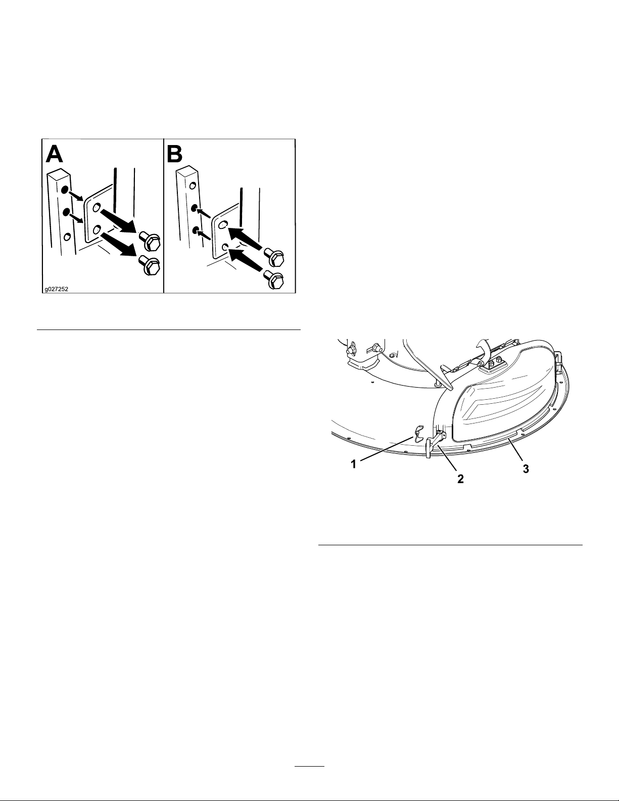
g027252
3.Releasetheexiblelatchfromthelatchretainer
onthedischargecoverandpivotthedischarge
covertotheright(Figure11).
AdjustingtheTilt
Youcanadjustthemotion-controlleversforwardor
rearwardforyourcomfort.
1.Loosentheupperboltholdingthecontrollever
tothecontrol-armshaft.
2.Loosenthelowerboltjustenoughtopivotthe
controlleverforwardorrearward(Figure10).
3.Tightenbothboltstosecurethecontrolleverin
thenewposition.
4.Repeattheadjustmentfortheothercontrollever.
g230251
Figure11
1.Latchretainer3.Dischargecover
2.Latch
4.Releasethehook-shapedlatchontopofthe
dischargecoverfromthepivotrod(Figure15).
5.Anglethemetaltabonthedischargecoverout
oftheslotinthebracketweldedtothemower
deck(Figure12).
19
Page 20
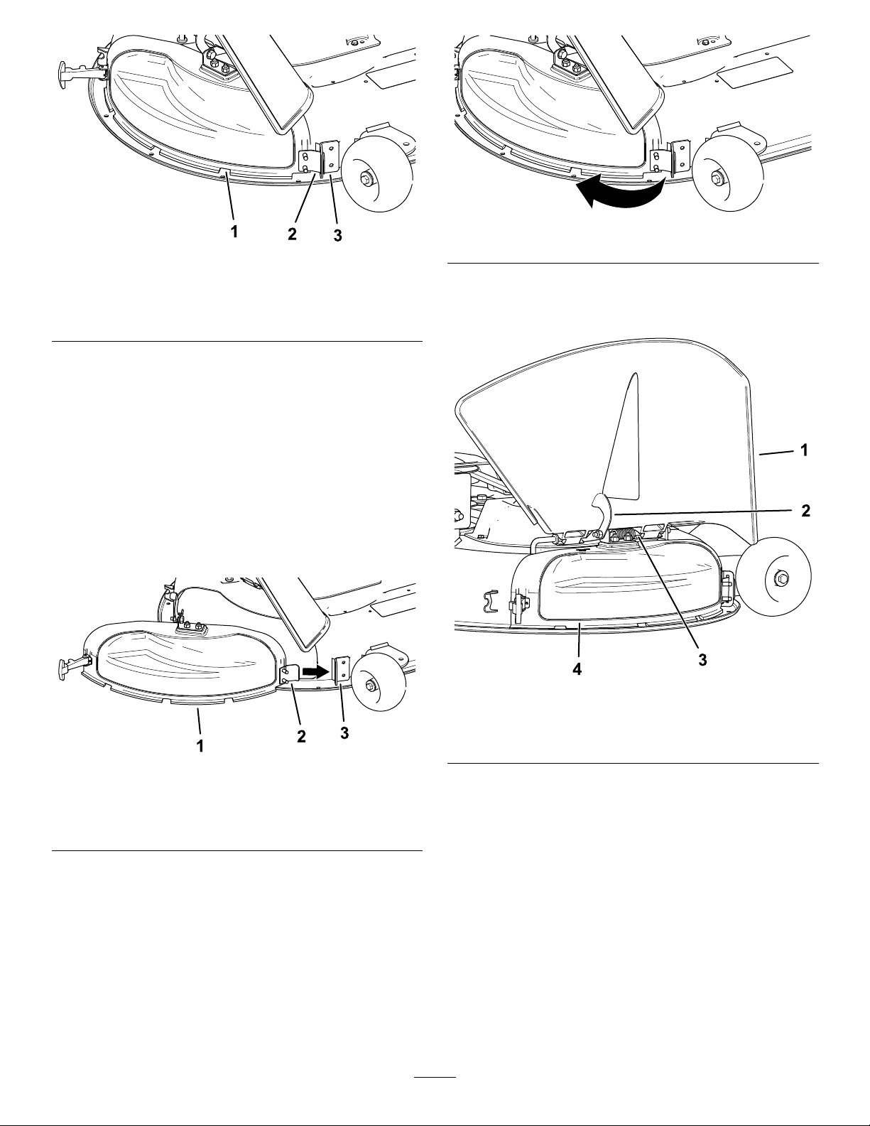
Figure12
1.Dischargecover3.Bracketonthemower
deck
2.Metaltab
InstallingtheDischargeCoverforMulching
1.Parkthemachineonalevelsurface,disengage
theblade-controlswitch,andengagetheparking
brake.
2.Shutofftheengine,removethekey,andwait
forallmovingpartstostopbeforeleavingthe
operatingposition.
3.Anglethemetaltabonthedischargecoverinto
theslotinthebracketweldedtothemowerdeck
(Figure13).
g230249
Figure14
g230250
5.Onthetopofthedischargecover,engagethe
hook-shapedlatcharoundthepivotrodofthe
deectorassembly(Figure15).
Figure13
1.Dischargecover3.Bracketonthemower
deck
2.Metaltab
4.Pivotthedischargecoverbackandtowardthe
decksothatthedischargecoveralignswiththe
mowerdeck(Figure14).
g230253
Figure15
1.Deector
2.Latch4.Dischargecover
g230248
3.Pivotrod
6.Securethedischargecovertothedeckby
hookingtheexiblelatchonthedischargecover
intotheretaineronthedeck(Figure11).
Machineswith127cm(50-inch) MowerDecks
Themowerdeckandmowerbladesshippedwiththe
machineweredesignedforoptimummulchingand
side-dischargeperformance.
20
Page 21

RemovingtheRightBafefor
Side-Discharging
1.Parkthemachineonalevelsurface,disengage
theblade-controlswitch,andengagetheparking
brake.
2.Shutofftheengine,removethekey,andwait
forallmovingpartstostopbeforeleavingthe
operatingposition.
3.Removetherightmowerblade;referto
RemovingtheBlades(page50).
4.Removethe2knobsandcurvedwashersthat
securetherightbafetothemower(Figure16).
g024261
Figure17
Figure16
1.Knob
2.Curvedwasher
3.Bafestudcomingthrough
themower
5.Removetherightbafeandlowerthegrass
deectoroverthedischargeopeningasshown
inFigure16andFigure17.
1.Rightbafe
g005655
2.Curvedwasherandknob
3.Dischargeopening
6.Installfastenersintotheholesinthetopofthe
mowertopreventyingdebris.
WARNING
Openholesinthemachineexposeyou
andotherstothrowndebristhatcan
causesevereinjury.
•Neveroperatethemachinewithout
hardwaremountedinallholesinthe
machinehousing.
•Installthehardwareinthemounting
holeswhenyouremovethemulching
bafe.
7.Installtherightmowerblade;refertoInstalling
theBlades(page51).
8.Liftupthegrassdeector.Install2bolts(5/16x
3/4inch)tothe2holesalongthedeckcutout.
9.Installthecutoffbafetothemowerdeck(Figure
18).
Note:Usethe2locknuts(5/16inch)tosecure
thebafetothemowerdeck.
Note:Thecutoffbafewasshippedwiththe
machineasaloosepart.
21
Page 22

Figure18
1.Bolt(5/16x3/4inch)3.Locknut(5/16inch)
2.Cutoffbafe
10.Torquethefastenersto7to9N∙m(14to18
ft-lb).
11.Lowerthegrassdeectoroverthedischarge
opening.
Important:Ensurethatthemowerhas
ahingedgrassdeectorthatdisperses
clippingstothesideanddowntowardthe
turfwhileinside-dischargemode.
InstallingtheRightBafeforMulching
1.Parkthemachineonalevelsurface,disengage
theblade-controlswitch,andengagetheparking
brake.
2.Shutofftheengine,removethekey,andwait
forallmovingpartstostopbeforeleavingthe
operatingposition.
3.Removethecutoffbafefromthemowerdeck
(Figure18).
4.Removetherightmowerblade;referto
RemovingtheBlades(page50).
5.Slidetherightbafeunderthemowerdeck,and
secureitusing2knobsandthecurvedwashers
(cuppedsidefacingthemower)asshownin
Figure16andFigure17.
Important:Ensurethatthetabonthefar
rightsideoftherightbafeisoutsideofthe
mowerandisushwiththemowerwall.
6.Installtherightmowerblade;refertoInstalling
theBlades(page51).
DuringOperation
DuringOperationSafety
GeneralSafety
•Theowner/operatorcanpreventandisresponsible
foraccidentsthatmaycausepersonalinjuryor
propertydamage.
g015321
•Wearappropriateclothing,includingeye
protection;longpants;slip-resistant,substantial
footwear;andhearingprotection.Tiebacklong
hairanddonotwearjewelry .
•Donotoperatethemachinewhileill,tired,or
undertheinuenceofalcoholordrugs.
•Nevercarrypassengersonthemachineandkeep
bystandersandpetsawayfromthemachine
duringoperation.
•Operatethemachineonlyingoodvisibilitytoavoid
holesorhiddenhazards.
•Avoidmowingonwetgrass.Reducedtraction
couldcausethemachinetoslide.
•Ensurethatalldrivesareinneutral,theparking
brakeisengaged,andyouareintheoperating
positionbeforeyoustarttheengine.
•Keepyourhandsandfeetawayfromthecutting
units.Keepclearofthedischargeopeningatall
times.
•Lookbehindanddownbeforebackinguptobe
sureofaclearpath.
•Usecarewhenapproachingblindcorners,shrubs,
trees,orotherobjectsthatmayobscureyour
vision.
•Donotmowneardrop-offs,ditches,or
embankments.Themachinecouldsuddenlyroll
overifawheelgoesovertheedgeoriftheedge
givesway .
•Stopthebladeswheneveryouarenotmowing.
•Stopthemachineandinspectthebladesafter
strikinganobjectorifthereisanabnormal
vibrationinthemachine.Makeallnecessary
repairsbeforeresumingoperation.
•Slowdownandusecautionwhenmakingturns
andcrossingroadsandsidewalkswiththe
machine.Alwaysyieldtheright-of-way.
•Disengagethedrivetothecuttingunitandshut
offtheenginebeforeadjustingtheheightof
cut(unlessyoucanadjustitfromtheoperating
position).
•Neverrunanengineinanareawhereexhaust
gasesareenclosed.
•Neverleavearunningmachineunattended.
22
Page 23

•Beforeleavingtheoperatingposition(including
toemptythecatchersortounclogthechute),do
thefollowing:
–Stopthemachineonlevelground.
–Disengagethepowertake-offandlowerthe
attachments.
–Engagetheparkingbrake.
–Shutofftheengineandremovethekey.
–Waitforallmovingpartstostop.
•Donotoperatethemachinewhenthereistherisk
oflightning.
•Donotusethemachineasatowingvehicleunless
ithasahitchinstalled.
•Donotchangethegovernorspeedoroverspeed
theengine.
•Useonlyaccessoriesandattachmentsapproved
byT oro.
•Thismachineproducessoundlevelsinexcess
of85dBAattheoperator’searandcancause
hearinglossthroughextendedperiodsof
exposure.
quicklyaffecttheoperationofthemachineon
aslope.
•Identifyhazardsatthebaseoftheslope.Do
notoperatethemachineneardrop-offs,ditches,
embankments,water,orotherhazards.The
machinecouldsuddenlyrolloverifawheelgoes
overtheedgeortheedgecollapses.Keepasafe
distance(twicethewidthofthemachine)between
themachineandanyhazard.Useawalk-behind
machineorahandtrimmertomowthegrassin
theseareas.
•Avoidstarting,stopping,orturningthemachineon
slopes.Avoidmakingsuddenchangesinspeedor
direction;turnslowlyandgradually .
•Donotoperateamachineunderanyconditions
wheretraction,steering,orstabilityisinquestion.
Beawarethatoperatingthemachineonwet
grass,acrossslopes,ordownhillmaycausethe
machinetolosetraction.Lossoftractiontothe
drivewheelsmayresultinslidingandalossof
brakingandsteering.Themachinecanslideeven
ifthedrivewheelsarestopped.
•Removeormarkobstaclessuchasditches,holes,
ruts,bumps,rocks,orotherhiddenhazards.T all
grasscanhideobstacles.Uneventerraincould
overturnthemachine.
Figure19
1.Wearhearingprotection.
SlopeSafety
•Slopesareamajorfactorrelatedtolossofcontrol
androlloveraccidents,whichcanresultinsevere
injuryordeath.Theoperatorisresponsiblefor
safeslopeoperation.Operatingthemachineon
anysloperequiresextracaution.Beforeusingthe
machineonaslope,dothefollowing:
–Reviewandunderstandtheslopeinstructions
inthemanualandonthemachine.
–Useanangleindicatortodeterminethe
approximateslopeangleofthearea.
–Neveroperateonslopesgreaterthan15
degrees.
•Useextracarewhileoperatingwithaccessoriesor
attachments,suchasgrass-collectionsystems.
Thesecanchangethestabilityofthemachine
g229846
andcausealossofcontrol.Followdirectionsfor
counterweights.
•Ifpossible,keepthedeckloweredtotheground
whileoperatingonslopes.Raisingthedeckwhile
operatingonslopescancausethemachineto
becomeunstable.
–Evaluatethesiteconditionsofthedayto
determineiftheslopeissafeformachine
operation.Usecommonsenseandgood
judgmentwhenperformingthisevaluation.
Changesintheterrain,suchasmoisture,can
23
Page 24

Figure20
OperatingtheMower Blade-ControlSwitch(PTO)
Theblade-controlswitch(PTO)startsandstopsthe
mowerbladesandanypoweredattachments.
EngagingtheBlade-Control Switch(PTO)
g22911 1
1.SafeZone—usethe
machinehereonslopes
lessthan15degreesor
atareas.
2.DangerZone—usea
walk-behindmowerand/or
ahandtrimmeronslopes
greaterthan15degrees
andneardrop-offsor
water.
3.Water
4.W=widthofthemachine
5.Keepasafedistance
(twicethewidthofthe
machine)betweenthe
machineandanyhazard.
TowingSafety
•Donotattachtowedequipmentexceptatthehitch
point.
•Followtheattachmentmanufacturer's
recommendationforweightlimitsfortowed
equipmentandtowingonslopes.Towedweight
mustnotexceedtheweightofthemachine,
operator,andballast.Usecounterweightsor
wheelweightsasdescribedintheattachment,or
intowingthemachineOperator’sManual.
•Neverallowchildrenorothersinoronthetowed
equipment.
g008945
Figure21
Note:Alwaysengagethebladeswiththethrottlein
theFASTposition(Figure22).
g187516
Figure22
•Onslopes,theweightofthetowedequipmentmay
causelossoftraction,increasedriskofrollover,
andlossofcontrol.Reducethetowedweightand
slowdown.
•Thestoppingdistanceincreaseswiththeweight
ofatowedload.Travelslowlyandallowextra
distancetostop.
•Makewideturnstokeeptheattachmentclearof
themachine.
24
Page 25

DisengagingtheBlade-Control Switch(PTO)
Figure23
OperatingtheThrottle
YoucanmovethethrottlecontrolbetweenFASTand
SLOWpositions(Figure24).
OperatingtheChoke
Usethechoketostartacoldengine.
1.Pullupthechokeknobtoengagethechoke
beforeusingthekeyswitch(Figure25).
Note:Ensurethatyoufullyengagethechoke.
Youmayneedtoholdtheknobupwhenyou
usethekeyswitch.
2.Pushdownthechoketodisengagethechoke
aftertheenginehasstarted(Figure25).
g027538
AlwaysusetheFASTpositionwhenengagingthePTO.
Figure24
g008959
Figure25
1.ONposition2.OFFposition
g187517
25
Page 26

StartingtheEngine
CAUTION
Note:Awarmorhotenginemaynotrequirechoking.
Important:Donotengagethestarterformore
than5secondsatatime.Engagingthestarter
motorformorethan5secondscandamagethe
startermotor.Iftheenginefailstostart,wait10
secondsbeforeoperatingtheenginestarteragain.
Childrenorbystandersmaybeinjuredifthey
moveorattempttooperatethemachinewhile
itisunattended.
Alwaysremovethekeyandengagethe
parkingbrakewhenleavingthemachine
unattended.
UsingtheMotion-Control Levers
Figure26
ShuttingOfftheEngine
1.Disengagethebladesbymovingthe
blade-controlswitchtotheOFFposition(Figure
26).
2.Engagetheparkingbrake;refertoParkPosition
(page15).
3.MovethethrottlecontroltotheFASTposition.
4.TurnthekeytotheOFFpositionandremove
thekey .
g004532
Figure27
g027581
1.Motion-control
lever—PARKposition
2.Center,unlockedposition5.Frontofmachine
3.Forward
4.Backward
DrivingtheMachine
Thedrivewheelsturnindependently,poweredby
hydraulicmotorsoneachaxle.Youcanturn1side
inreversewhileyouturntheotherforward,causing
themachinetospinratherthanturn.Thisgreatly
improvesthemachinemaneuverabilitybutmay
requiresometimeforyoutoadapttohowitmoves.
Thethrottlecontrolregulatestheenginespeedas
measuredinrpm(revolutionsperminute).Place
thethrottlecontrolintheFASTpositionforbest
26
Page 27

performance.Alwaysoperateinthefullthrottle
positionwhenmowing.
WARNING
Themachinecanspinveryrapidly.You
maylosecontrolofthemachineandcause
personalinjuryordamagetothemachine.
•Usecautionwhenmakingturns.
•Slowthemachinedownbeforemaking
sharpturns.
DrivingForward
Note:Alwaysusecautionwhenbackingupand
turning.
1.Movetheleverstothecenter,unlockedposition.
2.T ogoforward,slowlypushthemotion-control
leversforward(Figure28).
Figure28
g008953
Figure29
UsingtheSmartSpeed
TM
Control
System
TheSmartSpeed
belowtheoperatingposition(Figure30),givesthe
operatorachoicetodrivethemachineat3ground
speedranges—trim,tow,andmow.
g008952
TM
Control-Systemlever,located
DrivingBackward
1.Movetheleverstothecenter,unlockedposition.
2.T ogobackward,slowlypullthemotion-control
leversrearward(Figure29).
g027625
Figure30
1.Smart-speedlever
Tochangespeeds,dothefollowing:
1.Movethemotion-controlleverstoneutraland
outwardtothePARKposition.
2.Disengagetheblade-controlswitch.
3.Adjustthelevertothedesiredposition.
Thefollowingareonlyrecommendationsforuse.
Adjustmentsvarybygrasstype,moisturecontent,
andtheheightofthegrass.
27
Page 28

Suggested
uses:
ParkingX
Heavy,wet
grass
TrainingX
BaggingX
MulchingX
Normal
mowing
TransportX
TrimTowMow
X
X
Trim
Thisisthelowestspeed.Thesuggestedusesforthis
speedareasfollows:
•Parking
•Heavy,wetgrassmowingconditions
•Training
Tow
Thisisthemediumspeed.Thesuggestedusesfor
thisspeedareasfollows:
•Bagging
•Mulching
Mow
Thisisthefastestspeed.Thesuggestedusesforthis
speedareasfollows:
•Normalmowing
•Transportingthemachine
28
Page 29

UsingtheSideDischarge
Themowerhasahingedgrassdeectorthat
dispersesclippingstothesideanddowntowardthe
turf.
DANGER
Withoutagrassdeector,dischargecover,or
acompletegrass-catcherassemblymounted
inplace,youandothersareexposedtoblade
contactandthrowndebris.Contactwith
rotatingmowerblade(s)andthrowndebris
willcauseinjuryordeath.
•Neverremovethegrassdeectorfromthe
mowerdeckbecausethegrassdeector
routesmaterialdowntowardtheturf.Ifthe
grassdeectoriseverdamaged,replaceit
immediately.
•Neverputyourhandsorfeetunderthe
mowerdeck.
•Nevertrytoclearthedischargearea
ormowerbladesunlessyoumovethe
blade-controlswitch(PTO)totheOFF
position,rotatethekeyswitchtotheOFF
position,andremovethekeyfromthekey
switch.
g027697
Figure31
•Makesurethatthegrassdeectorisinthe
downposition.
AdjustingtheHeightofCut
Note:Thetransportpositionisthehighest
height-of-cutpositionorcuttingheightat1 15mm
(4-1/2inches)asshowninFigure31.
Heightofcutiscontrolledbytheleverlocatedtothe
rightoftheoperatingposition(Figure31).
29
Page 30

AdjustingtheAnti-Scalp Rollers
AdjustingtheAnti-ScalpRollers
Machineswith107cm(42-inch)MowerDecks
Wheneveryouchangetheheightofcut,adjustthe
heightoftheanti-scalprollers.
Note:Adjusttheanti-scalprollerssothattherollers
donottouchthegroundinnormal,atmowingareas.
1.Parkthemachineonalevelsurface,disengage
theblade-controlswitchandengagetheparking
brake.
2.Shutofftheengine,removethekey,andwait
forallmovingpartstostopbeforeleavingthe
operatingposition.
3.Adjusttheanti-scalprollersto1ofthefollowing
positions:
•Upperhole—usethispositionwiththemower
deckinthe63mm(2-1/2inches)andbelow
theheight-of-cutpositions(Figure32).
•Lowerhole—usethispositionwiththemower
deckinthe76mm(3inches)andabovethe
height-of-cutpositions(Figure32).
1.Parkthemachineonalevelsurface,disengage
theblade-controlswitchandengagetheparking
brake.
2.Shutofftheengine,removethekey,andwait
forallmovingpartstostopbeforeleavingthe
operatingposition.
3.Adjusttheanti-scalprollers(Figure33)tomatch
theclosestheight-of-cutposition.
Figure33
1.Anti-scalproller3.Flangenut
2.Bolt
4.Holespacing
g010233
Figure32
1.Anti-scalproller4.Upperhole—themower
2.Lowerhole—themower
deckinthe76mm(3
inches)andabovethe
height-of-cutpositions
3.Flangenut
deckinthe63mm(2-1/2
inches)andbelowthe
height-of-cutpositions
5.Bolt
AdjustingtheAnti-ScalpRollers
Machineswith127cm(50-inch)MowerDecks
Wheneveryouchangetheheightofcut,adjustthe
heightoftheanti-scalprollers.
Note:Adjusttheanti-scalprollerssothattherollers
donottouchthegroundinnormal,atmowingareas.
g019929
30
Page 31

OperatingTips
UsingtheFastThrottleSetting
dropontoyourlawn.Toavoidthis,moveontoa
previouslycutareawiththebladesengagedoryou
candisengagethemowerdeckwhilemovingforward.
Forbestmowingandmaximumaircirculation,operate
theengineattheFASTposition.Airisrequiredto
thoroughlycutgrassclippings,sodonotsetthe
height-of-cutsolowastototallysurroundthemower
deckinuncutgrass.Alwaystrytohave1sideofthe
mowerdeckfreefromuncutgrass,whichallowsair
tobedrawnintothemowerdeck.
CuttingaLawnfortheFirstTime
Cutgrassslightlylongerthannormaltoensurethat
thecuttingheightofthemowerdeckdoesnotscalp
anyunevenground.However,thecuttingheight
usedinthepastisgenerallythebestonetouse.
Whencuttinggrasslongerthan15cm(6inches)tall,
youmaywanttocutthelawntwicetoensurean
acceptablequalityofcut.
CuttingaThirdoftheGrassBlade
Itisbesttocutonlyaboutathirdofthegrassblade.
Cuttingmorethanthatisnotrecommendedunless
grassissparse,oritislatefallwhengrassgrows
moreslowly .
KeepingtheUndersideofthe
MowerDeckClean
Cleanclippingsanddirtfromtheundersideofthe
mowerdeckaftereachuse.Ifgrassanddirtbuildup
insidethemowerdeck,cuttingqualitywilleventually
becomeunsatisfactory.
MaintainingtheBlade(s)
Maintainasharpbladethroughoutthecuttingseason
becauseasharpbladecutscleanlywithouttearingor
shreddingthegrassblades.Tearingandshredding
turnsgrassbrownattheedges,whichslowsgrowth
andincreasesthechanceofdisease.Checkthe
mowerbladesaftereachuseforsharpness,and
foranywearordamage.Filedownanynicksand
sharpenthebladesasnecessary.Ifabladeis
damagedorworn,replaceitimmediatelywitha
genuineT ororeplacementblade.
AlternatingtheMowingDirection
Alternatethemowingdirectiontokeepthegrass
standingstraight.Thisalsohelpsdisperseclippings,
whichenhancesdecompositionandfertilization.
MowingatCorrectIntervals
Grassgrowsatdifferentratesatdifferenttimesof
theyear.Tomaintainthesamecuttingheight,mow
moreofteninearlyspring.Asthegrassgrowthrate
slowsinmidsummer,mowlessfrequently.Ifyou
cannotmowforanextendedperiod,rstmowata
highcuttingheight,thenmowagain2dayslaterata
lowerheightsetting.
UsingaSlowerCuttingSpeed
Toimprovecutquality,useaslowergroundspeed
incertainconditions.
AvoidingCuttingTooLow
Whenmowinguneventurf,raisethecuttingheight
toavoidscalpingtheturf.
StoppingtheMachine
Ifyoumuststoptheforwardmotionofthemachine
whilemowing,aclumpofgrassclippingsmay
31
Page 32

AfterOperation
AfterOperationSafety
GeneralSafety
•Cleangrassanddebrisfromthecuttingunits,
mufers,andenginecompartmenttohelpprevent
res.Cleanupoilorfuelspills.
•Shutoffthefuelbeforestoringortransportingthe
machine.
•Disengagethedrivetotheattachmentwhenever
youaretransportingornotusingthemachine.
•Allowtheenginetocoolbeforestoringthemachine
inanyenclosure.
•Neverstorethemachineorfuelcontainerwhere
thereisanopename,spark,orpilotlight,such
asonawaterheateroronotherappliances.
PushingtheMachineby Hand
Important:Alwayspushthemachinebyhand.
Donottowthemachine,becausetowingmay
damageit.
Figure34
1.Bypass-leverlocations
2.Leverpositionfor
operatingthemachine
6.Whennished,ensurethatthekeyhasbeen
returnedtotheSTOPpositiontoavoiddraining
thebatterycharge.
3.Leverpositionforpushing
themachine
Note:Ifthemachinefailstomove,theelectricbrake
maystillbeengaged.Youcanreleasetheelectric
brakemanuallyifnecessary;refertoReleasingthe
ElectricBrake(page46).
g017303
Thismachinehasanelectric-brakemechanism,and
topushthemachine,theignitionkeymustbeinthe
RUNposition.Thebatteryneedstobechargedand
functioningtodisengagetheelectricbrake.
PushingtheMachine
1.Parkthemachineonalevelsurface,disengage
theblade-controlswitch,andengagetheparking
brake.
2.Shutofftheengine,removethekey,andwait
forallmovingpartstostopbeforeleavingthe
operatingposition.
3.Locatethebypassleversontheframeonboth
sidesoftheengine.
4.Movethebypassleversforwardthroughthekey
holeanddowntolocktheminplace(Figure34).
Note:Dothisforeachlever.
5.Turntheignitionkeyonanddisengagethe
parkingbrake.
Note:Donotstartthemachine.
OperatingtheMachine
Movethebypassleversrearwardthroughthekeyhole
anddowntolocktheminplaceasshowninFigure34.
Note:Dothisforeachlever.
32
Page 33

TransportingtheMachine
Useaheavy-dutytrailerortrucktotransportthe
machine.Useafull-widthramp.Ensurethatthetrailer
ortruckhasallthenecessarybrakes,lighting,and
markingasrequiredbylaw.Pleasecarefullyreadall
thesafetyinstructions.Knowingthisinformationcould
helpyouorbystandersavoidinjury.Refertoyour
localordinancesfortrailerandtie-downrequirements.
WARNING
Drivingonthestreetorroadwaywithout
turnsignals,lights,reectivemarkings,ora
slow-moving-vehicleemblemisdangerous
andcanleadtoaccidents,causingpersonal
injury.
Donotdrivethemachineonapublicstreet
orroadway.
SelectingaTrailer
WARNING
Loadingamachineontoatrailerortruck
increasesthepossibilityoftip-overandcould
causeseriousinjuryordeath(Figure35).
•Useonlyafull-widthramp;donotuse
individualrampsforeachsideofthe
machine.
•Donotexceeda15-degreeanglebetween
therampandthegroundorbetweenthe
rampandthetrailerortruck.
•Ensurethatthelengthoframpisatleast4
timesaslongastheheightofthetraileror
truckbedtotheground.Thisensuresthat
rampangledoesnotexceed15degreeson
atground.
Figure35
1.Full-widthrampinstowed
position
2.Sideviewoffull-width
rampinloadingposition
3.Notgreaterthan
15degrees
4.Rampisatleast4times
aslongastheheightof
thetrailerortruckbedto
theground
5.H=heightofthetraileror
truckbedtotheground
6.Trailer
LoadingtheMachine
WARNING
Loadingamachineontoatrailerortruck
increasesthepossibilityoftip-overandcould
causeseriousinjuryordeath.
•Useextremecautionwhenoperatinga
machineonaramp.
g027996
•Backthemachineuptherampanddriveit
forwarddowntheramp.
•Avoidsuddenaccelerationordeceleration
whiledrivingthemachineonarampas
thiscouldcausealossofcontrolora
tip-oversituation.
33
Page 34

1.Ifusingatrailer,connectittothetowingvehicle
andconnectthesafetychains.
2.Ifapplicable,connectthetrailerbrakesand
lights.
3.Lowertheramp,ensuringthattheangle
betweentherampandthegrounddoesnot
exceed15degrees(Figure35).
4.Backthemachineuptheramp(Figure36).
Figure36
g027995
1.Backthemachineupthe
ramp.
2.Drivethemachineforward
downtheramp.
5.Shutofftheengine,removethekey,andengage
theparkingbrake.
6.Tiedownthemachinenearthefrontcaster
wheelsandtherearbumperwithstraps,chains,
cable,orropes(Figure37).Refertolocal
regulationsfortie-downrequirements.
Figure37
g027708
UnloadingtheMachine
1.Lowertheramp,ensuringthattheangle
betweentherampandthegrounddoesnot
exceed15degrees(Figure35).
2.Drivethemachineforwarddowntheramp
(Figure36).
34
Page 35

Maintenance
Note:Determinetheleftandrightsidesofthemachinefromthenormaloperatingposition.
RecommendedMaintenanceSchedule(s)
MaintenanceService
Interval
Aftertherst5hours
Beforeeachuseordaily
Aftereachuse
Every25hours
Every100hours
Every200hours
Beforestorage
MaintenanceProcedure
•Changetheengineoilandlter.
•Checkthesafety-interlocksystem.
•Checktheaircleanerfordirty,loose,ordamagedparts.
•Checktheengine-oillevel.
•Cleantheairintakescreen.
•Inspecttheblades.
•Inspectthegrassdeectorfordamage.
•Cleanthemower-deckhousing.
•Greaseallthelubricationpoints.
•Cleantheair-cleanerfoamelement(moreoftenindusty,dirtyconditions).
•Checktirepressure.
•Replacetheair-cleanerfoamelement(moreoftenindusty,dirtyconditions).
•Cleanthepaperair-cleanerelement(moreoftenindirtyordustyconditions).
•Changetheengineoilandoillter(moreoftenindirtyordustyconditions).
•Checkthesparkplug(s).
•Checkthein-linefuellter.
•Replacethepaperair-cleanerelement(moreoftenindirtyordustyconditions).
•Replacethesparkplug(s).
•Replacethein-linefuellter.
•Chargethebatteryanddisconnectthebatterycables.
•Performallmaintenanceprocedureslistedabovebeforestorage.
•Paintanychippedsurfaces.
CAUTION
Ifyouleavethekeyintheswitch,someonecouldaccidentlystarttheengineandseriously
injureyouorotherbystanders.
Removethekeyfromtheswitchbeforeyouperformanymaintenance.
35
Page 36

Pre-Maintenance
RaisingtheSeat
Procedures
MaintenanceSafety
•Beforerepairingthemachinedothefollowing:
–Disengagethedrives.
–Engagetheparkingbrake.
–Shutofftheengineandremovethekey.
–Disconnectthespark-plugwire.
•Parkthemachineonalevelsurface.
•Cleangrassanddebrisfromthecuttingunit,
drives,mufers,andenginetohelppreventres.
•Cleanupoilorfuelspills.
•Donotallowuntrainedpersonneltoservicethe
machine.
•Usejackstandstosupportthemachineand/or
componentswhenrequired.
•Carefullyreleasepressurefromcomponentswith
storedenergy.
Ensurethattheparkingbrakeisengaged.Liftthe
seatforward.
Youcanaccessfollowingcomponentsbyraisingthe
seat:
•Serialplate
•Servicedecal
•Seat-adjustmentbolts(ifapplicable)
•Fuellter
•Batteryandbatterycables
ReleasingtheMower-Deck Curtain
Loosenthe2bottomboltsofthecurtaintoaccessthe
topofthemowerdeck(Figure38).
•Disconnectthebatteryorremovethespark-plug
wirebeforemakinganyrepairs.Disconnectthe
negativeterminalrstandthepositiveterminal
last.Connectthepositiveterminalrstand
negativelast.
•Usecarewhencheckingtheblades.Wrapthe
blade(s)orwearthicklypaddedgloves,anduse
cautionwhenservicingthem.Onlyreplaceblades;
donotstraightenorweldthem.
•Keepyourhandsandfeetawayfrommoving
parts.Ifpossible,donotmakeadjustmentswith
theenginerunning.
•Keepallpartsingoodworkingcondition
andallhardwaretightened,especiallythe
blade-attachmentbolts.Replaceallwornor
damageddecals.
•Neverinterferewiththeintendedfunctionofa
safetydeviceorreducetheprotectionprovided
byasafetydevice.Checktheirproperoperation
regularly.
•Toensureoptimumperformanceandcontinued
safetycerticationofthemachine,useonly
genuineT ororeplacementpartsandaccessories.
Replacementpartsandaccessoriesmadeby
othermanufacturerscouldbedangerous,and
suchusecouldvoidtheproductwarranty.
Figure38
1.Bottombolt
2.Curtain
Note:Alwaystightentheboltstoconnectthecurtain
aftermaintenance.
g027794
•Checktheparkingbrakeoperationfrequently.
Adjustandserviceasrequired.
36
Page 37

Lubrication
EngineMaintenance
GreasingtheBearings
ServiceInterval:Every25hours—Greaseallthe
lubricationpoints.
GreaseType:No.2lithiumgrease
1.Parkthemachineonalevelsurface,disengage
theblade-controlswitch,andengagetheparking
brake;refertoParkPosition(page15).
2.Shutofftheengine,removethekey,andwait
forallmovingpartstostopbeforeleavingthe
operatingposition.
3.Cleanthegreasettings(Figure39andFigure
40)witharag.
Note:Scrapeanypaintoffthefrontofthe
tting(s).
EngineSafety
•Shutofftheenginebeforecheckingtheoilor
addingoiltothecrankcase.
•Keepyourhands,feet,face,clothing,andother
bodypartsawaythemuferandotherhotsurfaces.
ServicingtheAirCleaner
ServiceInterval:Beforeeachuseordaily
Note:Servicetheaircleanermorefrequently(every
fewhours)ifoperatingconditionsareextremelydusty
orsandy .
RemovingtheFoamandPaper Elements
1.Parkthemachineonalevelsurface,disengage
theblade-controlswitch(PTO),andengagethe
parkingbrake.
2.Shutofftheengine,removethekey,andwait
forallmovingpartstostopbeforeleavingthe
operatingposition.
Figure39
1.Frontcastertire
Figure40
Locatedontheseat-panunderside
1.Readtheinstructions
beforeservicingor
performingmaintenance
2.Checkthetirepressure
every25operatinghours
4.Connectagreaseguntoeachtting(Figure39
andFigure40).
3.Greaseevery25operating
hours
4.Engine
3.Cleanaroundtheair-cleanercovertoprevent
dirtfromgettingintotheengineandcausing
damage.
g032432
4.Liftthecoverandrotatetheair-cleanerassembly
outoftheengine(Figure41).
decal106-8717
5.Pumpgreaseintothettingsuntilgreasebegins
tooozeoutofthebearings.
6.Wipeupanyexcessgrease.
37
Page 38

ServicingtheFoamAir-Cleaner Element
ServiceInterval:Every25hours/Monthly(whichever
comesrst)—Cleantheair-cleaner
foamelement(moreoftenindusty,
dirtyconditions).
Every100hours/Y early(whichevercomes
rst)—Replacetheair-cleanerfoamelement
(moreoftenindusty ,dirtyconditions).
g027800
1.Washthefoamelementinliquidsoapand
warmwater.Whentheelementisclean,rinse
itthoroughly.
2.Drytheelementbysqueezingitinacleancloth.
Important:Replacethefoamelementifit
istornorworn.
ServicingthePaperAir-Cleaner Element
ServiceInterval:Every100hours—Cleanthepaper
air-cleanerelement(moreoftenin
dirtyordustyconditions).
Figure41
5.Separatethefoamandpaperelements(Figure
42).
Figure42
Every200hours—Replacethepaperair-cleaner
g027801
element(moreoftenindirtyordustyconditions).
1.Cleanthepaperelementbytappingitgentlyto
removedust.
Note:Ifitisverydirty ,replacethepaper
elementwithanewone.
2.Inspecttheelementfortears,anoilylm,or
damagetotherubberseal.
3.Replacethepaperelementifitisdamaged.
Important:Donotcleanthepaperlter.
g027802
38
Page 39

InstallingtheAirCleaner
1.Installthefoamelementoverthepaperelement.
ServicingtheEngineOil
Note:Ensurethatyoudonotdamagethe
elements.
2.Aligntheholesofthelterintothemanifold
ports.
3.Rotatethelterdownintothechamberandfully
seatitagainstthemanifold(Figure43).
Figure43
Engine-OilSpecications
OilType:Detergentoil(APIserviceSF ,SG,SH,SJ,
orSL)
CrankcaseCapacity:2.4L(81oz)withoillter
Viscosity:Seethetablebelow.
g029683
Figure44
CheckingtheEngine-OilLevel
g228022
ServiceInterval:Beforeeachuseordaily
Note:Checktheoilwhentheengineiscold.
4.Closethecover.
Important:Ifyouoverllorunderlltheengine
crankcasewithoilandruntheengine,youmay
damagetheengine.
1.Parkthemachineonalevelsurface,disengage
theblade-controlswitch(PTO),andengagethe
parkingbrake.
2.Shutofftheengine,removethekey,andwait
forallmovingpartstostopbeforeleavingthe
operatingposition.
Note:Ensurethattheengineiscoolsothatthe
oilhashadtimetodrainintothesump.
3.T okeepdirt,grassclippings,etc.,outofthe
engine,cleantheareaaroundtheoil-llcapand
dipstickbeforeremovingit(Figure45).
39
Page 40

Figure45
g027799
g193541
ChangingtheEngineOilandOil Filter
ServiceInterval:Aftertherst5hours/Afterthe
rstmonth(whichevercomes
rst)—Changetheengineoiland
lter.
Every100hours/Y early(whichevercomes
rst)—Changetheengineoilandoillter(more
oftenindirtyordustyconditions).
1.Parkthemachineonalevelsurfacetoensure
thattheoildrainscompletely.
2.Disengagetheblade-controlswitch(PTO)and
engagetheparkingbrake.
3.Shutofftheengine,removethekey,andwait
forallmovingpartstostopbeforeleavingthe
operatingposition.
4.Draintheoilfromtheengine.
g029570
Figure46
40
Page 41

5.Changetheengine-oillter(Figure47).
Note:Ensurethattheoil-ltergaskettouches
theengineandthenturnthelteranextra3/4
turn.
g193530
Figure48
Figure47
6.Slowlypourapproximately80%ofthespecied
oilintothellertubeandslowlyaddthe
additionaloiltobringittotheFullmark(Figure
48).
7.Disposeoftheusedoilatarecyclingcenter.
ServicingtheSparkPlug
ServiceInterval:Every100hours/Yearly(whichever
g027477
Every200hours/Every2years(whichever
comesrst)—Replacethesparkplug(s).
Ensurethattheairgapbetweenthecenterandside
electrodesiscorrectbeforeinstallingthesparkplug.
Useasparkplugwrenchforremovingandinstalling
thesparkplugandagappingtoolorfeelergaugeto
checkandadjusttheairgap.Installanewsparkplug
ifnecessary .
Type:Champion
Airgap:0.76mm(0.03inch)
RemovingtheSparkPlug
1.Parkthemachineonalevelsurface,disengage
theblade-controlswitch(PTO),andengagethe
parkingbrake.
comesrst)—Checkthespark
plug(s).
®
RN9YCorNGK
®
BPR6ES
2.Shutofftheengine,removethekey,andwait
forallmovingpartstostopbeforeleavingthe
operatingposition.
3.Cleantheareaaroundthebaseoftheplugto
keepdirtanddebrisoutoftheengine.
4.Removethesparkplug(Figure49).
41
Page 42

CleaningtheCooling System
1.Parkthemachineonalevelsurface,disengage
theblade-controlswitch(PTO),andengagethe
parkingbrake.
Figure49
CheckingtheSparkPlug
Important:Donotcleanthesparkplug(s).
Alwaysreplacethesparkplug(s)whenithasa
blackcoating,wornelectrodes,anoilylm,or
cracks.
Ifyouseelightbrownorgrayontheinsulator,the
engineisoperatingproperly.Ablackcoatingonthe
insulatorusuallymeanstheaircleanerisdirty .
Setthegapto0.75mm(0.03inch).
g027478
2.Shutofftheengine,removethekey,andwait
forallmovingpartstostopbeforeleavingthe
operatingposition.
3.Removetheairlterfromtheengine.
4.Removetheengineshroud.
5.T opreventdebrisenteringtheairintake,install
theairltertothelterbase.
6.Cleandebrisandgrassfromtheparts.
7.Removetheairlterandinstalltheengine
shroud.
8.Installtheairlter.
Figure50
InstallingtheSparkPlug
Figure51
g206628
g027960
42
Page 43

FuelSystem
Maintenance
DANGER
Incertainconditions,fuelisextremely
ammableandhighlyexplosive.Areor
explosionfromfuelcanburnyou,others,and
candamageproperty.
•Performanyfuel-relatedmaintenance
whentheengineiscold.Dothisoutdoors
inanopenarea.Wipeupanyfuelthat
spills.
•Neversmokewhendrainingfuel,andstay
awayfromanopenameorwhereaspark
mayignitethefuelfumes.
ReplacingtheIn-LineFuel Filter
g027939
ServiceInterval:Every100hours/Yearly(whichever
comesrst)—Checkthein-linefuel
lter.
Every200hours/Every2years(whichever
comesrst)—Replacethein-linefuellter.
Neverinstalladirtylterafterremovingitfromthe
fuelline.
1.Parkthemachineonalevelsurface,disengage
theblade-controlswitch(PTO),andengagethe
parkingbrake.
2.Shutofftheengine,removethekey,andwait
forallmovingpartstostopbeforeleavingthe
operatingposition.
g033082
Figure52
43
Page 44

ElectricalSystem
Maintenance
ElectricalSystemSafety
•Disconnectthebatterybeforerepairingthe
machine.Disconnectthenegativeterminalrst
andthepositivelast.Connectthepositiveterminal
rstandthenegativelast.
•Chargethebatteryinanopen,well-ventilated
area,awayfromsparksandames.Unplugthe
chargerbeforeconnectingordisconnectingthe
battery.Wearprotectiveclothinganduseinsulated
tools.
ServicingtheBattery
RemovingtheBattery
WARNING
Incorrectlyremovingthecablesfrom
batterycoulddamagethemachineand
cables,causingsparks.Sparkscan
causethebatterygassestoexplode,
resultinginpersonalinjury .
•Alwaysdisconnectthenegative
(black)batterycablebefore
disconnectingthepositive(red)
cable.
•Alwaysconnectthepositive(red)
batterycablebeforeconnectingthe
negative(black)cable.
5.Slidetherubbercoveroffthepositive(red)
cable.
6.Disconnectthepositive(red)cablefromthe
batterypost(Figure53).
Note:Retainallfasteners.
WARNING
Batteryterminalsormetaltoolscouldshort
againstmetalmachinecomponents,causing
sparks.Sparkscancausethebatterygasses
toexplode,resultinginpersonalinjury.
•Whenremovingorinstallingthebattery ,
donotallowthebatteryterminalstotouch
anymetalpartsofthemachine.
•Donotallowmetaltoolstoshortbetween
thebatteryterminalsandmetalpartsofthe
machine.
1.Parkthemachineonalevelsurface,disengage
theblade-controlswitch(PTO),andengagethe
parkingbrake.
2.Shutofftheengine,removethekey,andwait
forallmovingpartstostopbeforeleavingthe
operatingposition.
3.Raisetheseattoaccessthebattery.
4.Disconnectthenegative(black)groundcable
fromthebatterypost(Figure53).
Note:Retainallfasteners.
7.Removethebatteryhold-down(Figure53),and
liftthebatteryfromthebatterytray.
Figure53
1.Battery
2.Positive(+)batterypost
3.Bolt,washer,andnut7.Batteryhold-down
4.Terminalboot
5.Negative(–)batterypost
6.Wingnut,washer,andbolt
g017701
ChargingtheBattery
ServiceInterval:Beforestorage—Chargethebattery
anddisconnectthebatterycables.
1.Removethebatteryfromthechassis;referto
RemovingtheBattery(page44).
44
Page 45

2.Chargethebatteryforaminimumof1hourat
6to10A.
Note:Donotoverchargethebattery .
3.Whenthebatteryisfullycharged,unplug
thechargerfromtheelectricaloutlet,then
disconnectthechargerleadsfromthebattery
posts(Figure54).
Figure54
1.Positive(+)batterypost3.Red(+)chargerlead
2.Negative(–)batterypost4.Black(–)chargerlead
ServicingtheFuses
Theelectricalsystemisprotectedbyfuses.Itrequires
nomaintenance;however,ifafuseblows,checkthe
component/circuitforamalfunctionorshort.
Fusetype:
•Main—F1(30A,blade-type)
•ChargeCircuit—F2(25A,blade-type)
1.Removethescrewssecuringthecontrolpanel
tothemachine.
Note:Retainallfasteners.
2.Liftthecontrolpaneuptoaccessthemainwire
harnessandfuseblock(Figure55).
3.T oreplaceafuse,pulloutthefusetoremove
it(Figure55).
g000538
InstallingtheBattery
1.Positionthebatteryinthetray(Figure53).
2.Usingthefastenerspreviouslyremoved,install
thepositive(red)batterycabletothepositive
(+)batteryterminal.
3.Usingthefastenerspreviouslyremoved,install
thenegativebatterycabletothenegative(-)
batteryterminal.
4.Slidetheredterminalbootontothepositive
(red)batterypost.
5.Securethebatterywiththehold-down(Figure
53).
6.Lowertheseat.
g014921
Figure55
1.Main(30A)2.Chargecircuit(25A)
4.Returnthecontrolpaneltoitsoriginalposition.
Note:Usethescrewsremovedpreviouslyto
securethepaneltothemachine.
45
Page 46

DriveSystem
ReleasingtheElectric
Maintenance
CheckingtheTirePressure
ServiceInterval:Every25hours—Checktire
pressure.
Maintaintheairpressureinthefrontandreartiresas
specied.Uneventirepressurecancauseanuneven
cut.Checkthepressureatthevalvestem(Figure56).
Checkthetireswhentheyarecoldtogetthemost
accuratepressurereading.
Refertothemaximumpressuresuggestedbythetire
manufactureronthesidewallofthecasterwheeltires.
Inatethereardrive-wheeltiresto90kPa(13psi).
Brake
Youcanmanuallyreleasetheelectricbrakeby
rotatingthelinkarmsforward.Oncetheelectricbrake
isenergized,thebrakeresets.
1.TurnthekeytotheOFFpositionordisconnect
thebattery .
2.Loosenthebottom2boltsholdingthe
mower-deckcurtaintothemowerdeck.Referto
ReleasingtheMower-DeckCurtain(page36).
3.Locatetheshaftontheelectricbrakewherethe
brakelinkarmsareconnected(Figure57).
4.Rotatetheshaftforwardtoreleasethebrake.
5.Tightenthebottom2boltsforthemower-deck
curtaintothemowerdeck.RefertoReleasing
theMower-DeckCurtain(page36).
1.Valvestem
g000554
Figure56
g027911
Figure57
1.Brake-linkarmontheelectricbrakecontrolmodule
2.Left,reartire
46
Page 47

BeltMaintenance
ReplacingtheMower-Deck Belt
Thesignsofawornbeltincludesquealingwhilethe
beltisrotating,bladesslippingwhilecuttinggrass,
andfrayededges,burnmarks,andcracksonthebelt.
Replacethemowerbeltifanyoftheseconditionsare
evident.
1.Parkthemachineonalevelsurface,disengage
theblade-controlswitch(PTO),andengagethe
parkingbrake.
2.Shutofftheengine,removethekey,andwait
forallmovingpartstostopbeforeleavingthe
operatingposition.
3.Settheheight-of-cutatthelowestcutting
positionof38mm(1-1/2inches).
4.Removethepulleycovers(Figure58).
Figure59
MowerDeckswith2Blades
1.Idlerpulley
2.Mowerbelt
3.Outsidepulley6.Spring-removaltool
4.Spring
5.Enginepulley
g014930
Figure58
1.Cover2.Screw
5.Loosenthebottom2boltsholdingthe
mower-deckcurtaintothemowerdeck.Referto
ReleasingtheMower-DeckCurtain(page36).
6.Usingaspring-removaltool,(T oroPartNo.
92-5771),removetheidlerspringfromthedeck
hooktoremovetensionontheidlerpulley,and
rollthebeltoffthepulleys(Figure59andFigure
60).
WARNING
Thespringisundertensionwhen
installedandcancausepersonalinjury.
Becarefulwhenremovingthebelt.
g032555
g014931
Figure60
MowerDeckswith3Blades
1.Idlerpulley
2.Mowerbelt5.Enginepulley
3.Outsidepulley6.Spring-removaltool
4.Spring
7.Routethenewbeltaroundtheenginepulleyand
mowerpulleys(Figure60).
47
Page 48

8.Usingaspring-removaltool,installtheidler
springoverthedeckhook,andplacetensionon
theidlerpulleyandmowerbelt(Figure59and
Figure60).
9.Tightenthebottom2boltsforthemower-deck
curtaintothemowerdeck.RefertoReleasing
theMower-DeckCurtain(page36).
10.Installthepulleycovers.
MowerMaintenance
ServicingtheCutting Blades
Toensureasuperiorqualityofcut,keeptheblades
sharp.Forconvenientsharpeningandreplacement,
keepextrabladesonhand.
BladeSafety
Awornordamagedbladecanbreak,andapieceof
thebladecouldbethrowntowardyouorbystanders,
resultinginseriouspersonalinjuryordeath.Tryingto
repairadamagedblademayresultindiscontinued
safetycerticationoftheproduct.
•Inspectthebladesperiodicallyforwearordamage.
•Usecarewhencheckingtheblades.Wrapthe
bladesorweargloves,andusecautionwhen
servicingtheblades.Onlyreplaceorsharpenthe
blades;neverstraightenorweldthem.
•Onmulti-bladedmachines,takecareasrotating1
bladecancauseotherbladestorotate.
BeforeInspectingorServicingthe Blades
1.Parkthemachineonalevelsurface,disengage
theblade-controlswitch(PTO),andengagethe
parkingbrake.
2.Shutofftheengine,removethekey ,and
disconnectthespark-plugwiresfromthespark
plugs.
InspectingtheBlades
ServiceInterval:Beforeeachuseordaily
1.Inspectthecuttingedges(Figure61).
2.Iftheedgesarenotsharporhavenicks,remove
andsharpentheblade;refertoSharpeningthe
Blades(page50).
3.Inspecttheblades,especiallyinthecurvedarea.
4.Ifyounoticeanycracks,wear,oraslotforming
inthisarea,immediatelyinstallanewblade
(Figure61).
48
Page 49

Figure61
g006530
1.Cuttingedge3.Wear/slotforming
2.Curvedarea4.Crack
CheckingforBentBlades
Note:Themachinemustbeonalevelsurfacefor
thefollowingprocedure.
1.Raisethemowerdecktothehighest
height-of-cutposition.
2.Whilewearingthicklypaddedgloves,orother
adequatehandprotection,slowlyrotatethe
bladeintoapositionthatallowsyoutomeasure
thedistancebetweenthecuttingedgeandthe
levelsurfacethemachineison(Figure62).
Figure62
1.Deck3.Blade
2.Spindlehousing
3.Measurefromthetipofthebladetotheat
surface(Figure63).
g014973
Figure63
1.Blade(inpositionformeasuring)
2.Levelsurface
3.Measureddistancebetweenbladeandthesurface(A)
4.Rotatethesameblade180degreessothat
theopposingcuttingedgeisnowinthesame
position(Figure64).
g014974
Figure64
1.Blade(sidepreviouslymeasured)
2.Measurement(positionusedpreviously)
3.Opposingsideofbladebeingmovedintomeasurement
g014972
position
5.Measurefromthetipofthebladetotheat
surface(Figure65).
Note:Thevarianceshouldbenomorethan
3mm(1/8inch).
49
Page 50

Figure65
1.Oppositebladeedge(inpositionformeasuring)
2.Levelsurface
3.Secondmeasureddistancebetweenbladeandsurface(B)
A.IfthedifferencebetweenAandBisgreater
than3mm(1/8inch),replacethebladewith
anewblade;refertoRemovingtheBlades
(page50)andInstallingtheBlades(page
51).
g014973
g027833
Figure66
1.Sailareaoftheblade3.Curvedwasher
2.Blade4.Bladebolt
SharpeningtheBlades
1.Usealetosharpenthecuttingedgeatboth
endsoftheblade(Figure67).
Note:Ifabentbladeisreplacedwitha
newblade,andthedimensionobtained
continuestoexceed3mm(1/8inch),the
bladespindlecouldbebent.Contactan
AuthorizedServiceDealerforservice.
B.Ifthevarianceiswithinconstraints,moveto
thenextblade.
6.Repeatthisprocedureoneachblade.
RemovingtheBlades
Replacethebladesiftheyhitasolidobject,orifthe
bladeisoutofbalanceorbent.
1.Holdthebladeendusingaragorthicklypadded
glove.
2.Removethebladebolt,curvedwasher,and
bladefromthespindleshaft(Figure66).
Note:Maintaintheoriginalangle.
Note:Thebladeretainsitsbalanceifthesame
amountofmaterialisremovedfrombothcutting
edges.
g000552
Figure67
1.Sharpenatoriginalangle.
2.Checkthebalanceofthebladebyputtingitona
bladebalancer(Figure68).
Note:Ifthebladestaysinahorizontalposition,
thebladeisbalancedandcanbeused.
Note:Ifthebladeisnotbalanced,lesome
metalofftheendofthesailareaonly(Figure67).
Figure68
1.Blade2.Balancer
3.Repeatthisprocedureuntilthebladeis
balanced.
50
g000553
Page 51

InstallingtheBlades
1.Installthebladeontothespindleshaft(Figure
66).
Important:Thecurvedpartoftheblade
mustbepointingupwardtowardtheinside
ofthemowertoensurepropercutting.
2.Installthecurvedwasher(cuppedsidetoward
theblade)andthebladebolt(Figure66).
3.T orquethebladeboltto47to88N∙m(35to65
ft-lb).
LevelingtheMowerDeck
Checktoensurethatthemowerdeckislevelanytime
youinstallthemowerorwhenyouseeanunevencut
onyourlawn.
Checkthemowerdeckforbentbladespriorto
leveling,andremoveandreplaceanybentblades;
refertotheCheckingforBentBlades(page49)before
continuing.
Figure69
MowerDeckswith2Blades
1.Bladessidetoside
2.Sailareaoftheblade4.Measurefromthetipofthe
3.Outsidecuttingedges
bladetotheatsurface
here.
g009682
Levelthemowerdeckside-to-siderst;thenyoucan
adjustthefront-to-rearslope.
Requirements:
•Themachinemustbeonalevelsurface.
•Alltiresmustbeproperlyinated;refertoChecking
theTirePressure(page46).
LevelingfromSidetoSide
1.Parkthemachineonalevelsurface,disengage
theblade-controlswitch(PTO),andengagethe
parkingbrake.
2.Shutofftheengine,removethekey,andwait
forallmovingpartstostopbeforeleavingthe
operatingposition.
3.Settheheight-of-cutlevertothemiddleposition.
4.Carefullyrotatethebladessothattheyareall
sidetoside(Figure69andFigure70).
Figure70
MowerDeckswith3Blades
1.Bladessidetoside
2.Sailareaoftheblade4.Measurefromthetipofthe
3.Outsidecuttingedges
bladetotheatsurface
here.
5.Measurebetweentheoutsidecuttingedgesand
theatsurface(Figure69andFigure70).
Note:Ifbothmeasurementsarenotwithin
5mm(3/16inch),anadjustmentisrequired;
continuewiththisprocedure.
6.Movetotheleftsideofthemachine.
7.Loosenthesidelockingnut.
8.Raiseorlowertheleftsideofthemowerdeck
byrotatingtherearnut(Figure71).
g005278
Note:Rotatetherearnutclockwiseto
raisethemowerdeck;rotatetherearnut
counter-clockwisetolowerthemowerdeck
(Figure71).
51
Page 52

Figure71
1.Hangerbracket3.Rearnut
2.Sidelockingnut
9.Checktheside-to-sideadjustmentsagain.
Repeatthisprocedureuntilthemeasurements
arecorrect.
g009658
Figure72
MowerDeckswith2Blades
1.Bladesfronttorear
2.Measurefromthetipofthebladetotheatsurfacehere.
g027588
10.Continuelevelingthemowerdeckbychecking
thefront-to-rearbladeslope;refertoAdjusting
theFront-to-RearBladeSlope(page52).
AdjustingtheFront-to-RearBlade Slope
Checkthefront-to-rearbladelevelanytimeyouinstall
themower.Ifthefrontofthemowerismorethan
7.9mm(5/16inch)lowerthantherearofthemower,
adjustthebladelevelusingthefollowinginstructions:
1.Parkthemachineonalevelsurface,disengage
theblade-controlswitch(PTO),andengagethe
parkingbrake.
2.Shutofftheengine,removethekey,andwait
forallmovingpartstostopbeforeleavingthe
operatingposition.
3.Settheheight-of-cutlevertothemiddleposition.
Note:Checkandadjusttheside-to-sideblade
levelifyouhavenotcheckedthesetting;referto
LevelingfromSidetoSide(page51).
g009659
Figure73
MowerDeckswith3Blades
1.Bladesfronttorear3.Measurefromthetipofthe
bladetotheatsurface
here.
2.Outsidecuttingedges
5.Measurefromthetipofthefrontbladetotheat
surface,andthetipoftherearbladetotheat
surface(Figure72andFigure73).
Note:Ifthefrontbladetipisnot1.6to7.9mm
(1/16to5/16inch)lowerthantherearbladetip,
adjustthefrontlocknut.
6.T oadjustthefront-to-rearbladeslope,rotatethe
adjustmentnutinthefrontofthemower(Figure
74).
4.Carefullyrotatethebladessotheyarefacing
fronttorear(Figure72andFigure73).
52
Page 53

Figure74
1.Adjustingrod3.Locknut
2.Adjustingblock
7.T oraisethefrontofthemower,tightenthe
adjustmentnut.
8.T olowerthefrontofthemower,loosenthe
adjustmentnut.
9.Afteradjustment,checkthefront-to-rearslope
again,continueadjustingthenutuntilthefront
bladetipis1.6to7.9mm(1/16to5/16inch)
lowerthantherearbladetip(Figure72and
Figure73).
10.Whenthefront-to-rearbladeslopeiscorrect
checktheside-to-sidelevelofthemoweragain,
refertoLevelingfromSidetoSide(page51).
RemovingtheMowerDeck
1.Parkthemachineonalevelsurface,disengage
theblade-controlswitch(PTO),andengagethe
parkingbrake.
g014634
g014635
Figure75
1.Frontsupportrod3.Deckbracket
2.Lockingnut
6.Carefullylowerthefrontofthemowerdeckto
theground.
7.Liftthemowerdeckandhangerbracketsclear
oftherearliftrodandlowerthemowercarefully
totheground(Figure76).
2.Shutofftheengine,removethekey,andwait
forallmovingpartstostopbeforeleavingthe
operatingposition.
3.Lowertheheight-of-cutlevertothelowest
position.
4.Loosenthebottom2boltsholdingthe
mower-deckcurtaintothemowerdeck.Referto
ReleasingtheMower-DeckCurtain(page36).
5.Removethehairpincotterfromthefrontsupport
rod,andremovetherodfromthedeckbracket
(Figure75).
Figure76
1.Mowerdeck
2.Hangerbracket
3.Rearliftrod
8.Slidethemowerdeckrearwardtoremovethe
mowerbeltfromtheenginepulley.
53
g005077
Page 54

9.Slidethemowerdeckoutfromunderneaththe
machine.
Note:Retainallpartsforfutureinstallation.
InstallingtheMowerDeck
1.Parkthemachineonalevelsurface,disengage
theblade-controlswitch(PTO),andengagethe
parkingbrake.
2.Shutofftheengine,removethekey,andwait
forallmovingpartstostopbeforeleavingthe
operatingposition.
3.Slidethemowerunderthemachine.
4.Lowertheheight-of-cutlevertothelowest
position.
5.Lifttherearofthemowerdeckandguidethe
hangerbracketsovertherearliftrod(Figure74).
6.Attachthefrontsupportrodtothemowerdeck
withtheclevispinandhairpincotter(Figure74).
7.Installthemowerbeltontotheenginepulley;
refertoReplacingtheMower-DeckBelt(page
47).
8.Tightenthebottom2boltsforthemower-deck
curtaintothemowerdeck;refertoReleasing
theMower-DeckCurtain(page36).
ReplacingtheGrass
Deector
ServiceInterval:Beforeeachuseordaily—Inspect
thegrassdeectorfordamage.
WARNING
Anuncovereddischargeopeningcouldallow
themachinetothrowobjectstowardyouor
bystanders,resultinginseriousinjury.Also,
contactwiththebladecouldoccur.
Neveroperatethemachinewithoutthe
grassdeector,thedischargecover,orthe
grass-collectionsysteminplace.
Figure77
1.Mowerdeck
2.Grassdeector6.Nut(3/8inch)
3.Grass-deectorbracket7.Shortstandoff
4.Rod
2.Slidetherodoutoftheshortstand-off,spring,
andgrassdeector(Figure77).
3.Removethedamagedorworngrassdeector.
4.Replacethegrassdeector(Figure77).
5.Slidetherod,straightend,throughtherear
grassdeectorbracket.
6.Placethespringontherod,withendwires
down,andbetweenthegrassdeectorbrackets.
7.Slidetherodthroughthesecondgrass-deector
bracket(Figure77).
8.Inserttherodatthefrontofthegrassdeector
intotheshortstandoffonthedeck.
9.Securetherearendoftherodintothemower
withanut(3/8inch)asshowninFigure77.
5.Spring
Important:Thegrassdeectormustbe
spring-loadedinthedownposition.Liftthe
deectoruptotestthatitsnapsintothe
full-downposition.
g005192
1.Removethenut(3/8inch)fromtherodunder
themower(Figure77).
54
Page 55

Cleaning
8.Turnthewateroffandremovethecouplingfrom
thewashouttting.
WashingtheUndersideof theMowerDeck
ServiceInterval:Aftereachuse—Cleanthe
mower-deckhousing.
Important:Youcanwashthemachinewithamild
detergentandwater.Donotpressurewashthe
machine.Avoidexcessiveuseofwater,especially
nearthecontrolpanel,undertheseat,aroundthe
engine,hydraulicpumps,andmotors.
Washtheundersideofthemowerdeckaftereachuse
topreventgrassbuildupforimprovedmulchaction
andclippingdispersal.
1.Parkthemachineonalevelsurface,disengage
theblade-controlswitch(PTO),andengagethe
parkingbrake.
2.Shutofftheengine,removethekey,andwait
forallmovingpartstostopbeforeleavingthe
operatingposition.
3.Attachthehosecouplingtotheendofthe
mowerwashouttting,andturnthewateron
high(Figure78).
Note:Spreadpetroleumjellyonthewashout
ttingO-ringtomakethecouplingslideon
easierandprotecttheO-ring.
Note:Ifthemowerisnotcleanafter1washing,
soakitandletitstandfor30minutes.Then,
repeattheprocess.
9.Runthemoweragainfor1to3minutesto
removeexcesswater.
WARNING
Abrokenormissingwashouttting
couldexposeyouandotherstothrown
objectsorbladecontact.Contactwitha
bladeorthrowndebriscancauseinjury
ordeath.
•Replacebrokenormissingwashout
ttingimmediately,beforeusing
machineagain.
•Neverputyourhandsorfeetunder
themowerorthroughopeningsinthe
machine.
DisposingofWaste
Engineoil,batteries,hydraulicuid,andengine
coolantarepollutantstotheenvironment.Disposeof
theseaccordingtoyourstateandlocalregulations.
Figure78
1.Washouttting3.O-ring
2.Hose
4.Lowerthemowertothelowestheight-of-cut.
5.Sitontheseatandstarttheengine.
6.Engagetheblade-controlswitchandletthe
mowerrunfor1to3minutes.
7.Disengagetheblade-controlswitch,shutoffthe
engine,removetheignitionkey,andwaitforall
movingpartstostop.
4.Coupling
g020098
55
Page 56

Storage
StorageSafety
•Lettheenginecoolbeforestoringthemachine.
•Donotstorethemachineorfuelnearamesor
drainthefuelindoors.
thestabilizermanufacturer.Donotuse
analcohol-basedstabilizer(ethanolor
methanol).
Note:Afuelstabilizer/conditionerismost
effectivewhenmixedwithfreshfueland
usedatalltimes.
B.Runtheenginetodistributeconditionedfuel
throughthefuelsystem(5minutes).
CleaningandStorage
1.Disengagetheblade-controlswitch(PTO),and
engagetheparkingbrake.
2.Shutofftheengine,removethekey,andwait
forallmovingpartstostopbeforeleavingthe
operatingposition.
3.Removegrassclippings,dirt,andgrimefromthe
externalpartsoftheentiremachine,especially
theengineandhydraulicsystem.Cleandirtand
chafffromtheoutsideoftheenginecylinder
headnsandblowerhousing.
Important:Youcanwashthemachinewith
milddetergentandwater.Donotpressure
washthemachine.Avoidexcessiveuse
ofwater,especiallynearthecontrolpanel,
engine,hydraulicpumps,andmotors.
4.Checktheparkingbrakeoperation;refertoPark
Position(page15).
5.Servicetheaircleaner;refertoServicingtheAir
Cleaner(page37).
6.Greasethemachine;refertoLubrication(page
37).
7.Changethecrankcaseoil;refertoChangingthe
EngineOilandOilFilter(page40).
8.Checkthetirepressure;refertoCheckingthe
TirePressure(page46).
C.Shutofftheengine,allowittocool,and
drainthefueltank.
D.Starttheengineandrunituntilitstops.
E.Disposeoffuelproperly.Recyclethefuel
accordingtolocalcodes.
Important:Donotstore
stabilizer/conditionedfuelover
90days.
13.Removeandchecktheconditionofthespark
plug(s);refertoServicingtheSparkPlug(page
41).Withthesparkplug(s)removedfromthe
engine,pour30ml(2tablespoons)ofengine
oilintothesparkplughole.Usethestarterto
cranktheengineanddistributetheoilinsidethe
cylinder.Installthesparkplug(s).Donotinstall
thewireonthesparkplug(s).
14.Checkandtightenallbolts,nuts,andscrews.
Repairorreplaceanypartthatisdamaged.
15.Paintallscratchedorbaremetalsurfaces.Paint
isavailablefromyourAuthorizedServiceDealer.
16.Storethemachineinaclean,drygarageor
storagearea.Removethekeyfromtheswitch
andkeepitoutofreachofchildrenorother
unauthorizedusers.Coverthemachineto
protectitandkeepitclean.
9.Chargethebattery;refertoChargingtheBattery
(page44).
10.Scrapeanyheavybuildupofgrassanddirt
fromtheundersideofthemower,thenwashthe
mowerwithagardenhose.
Note:Runthemachinewiththeblade-control
switch(PTO)engagedandtheengineathigh
idlefor2to5minutesafterwashing.
11.Checktheconditionoftheblades;referto
ServicingtheCuttingBlades(page48).
12.Preparethemachineforstoragewhennon-use
occursover30days.Preparethemachinefor
storageasfollows:
A.Addapetroleumbased
stabilizer/conditionertofuelinthe
tank.Followmixinginstructionsfrom
56
Page 57

StoringtheBattery
1.Fullychargethebattery .
2.Letthebatteryrestfor24hours,thencheckthe
batteryvoltage.
Note:Ifthebatteryvoltageisbelow12.6V ,
repeatsteps1and2.
3.Disconnectthecablesfromthebattery.
4.Checkthevoltageperiodicallytoensurethatthe
voltageis12.4Vorhigher.
Note:Ifthebatteryvoltageisbelow12.4V ,
repeatsteps1and2.
BatteryStorageTips
•Storethebatteryinacool,dryareainanupright
position.
•Donotstackbatteriesdirectlyontopofeachother,
unlesstheyareincartons.
•Donotstackmorethan3batteries(only2ifthe
batterytypeiscommercial).
•Testawetbatteryevery4to6monthsandcharge
it,ifnecessary .
•Alwaystestandchargethebatterybefore
installation.
57
Page 58

Troubleshooting
Problem
Thefueltankisshowingsignsofcollapsing
orthemachineisfrequentlyshowingsigns
ofrunningoutoffuel.
Theengineoverheats.
Thestarterdoesnotcrank.
Theenginedoesnotstart,startshard,or
failstokeeprunning.
PossibleCauseCorrectiveAction
1.Theair-cleanerpaperelementclogged.
1.Theengineloadisexcessive.1.Reducethegroundspeed.
2.Theoillevelinthecrankcaseislow.2.Addoiltothecrankcase.
3.Thecoolingnsandairpassages
undertheengine-blowerhousingare
plugged.
4.Theaircleanerisdirty.
5.Dirt,water,orstalefuelisinthefuel
system.
1.Theblade-controlswitchisengaged.1.Disengagetheblade-controlswitch.
2.Themotion-controlleversarenotin
thePARKposition.
3.Thebatteryisdead.
4.Theelectricalconnectionsare
corrodedorloose.
5.Afuseisblown.5.Replacethefuse.
6.Arelayorswitchisdamaged.
1.Thefueltankisempty.1.Fillthefueltank.
2.Thechoke(ifapplicable)isnoton.
3.Theaircleanerisdirty.
4.Thespark-plugwire(s)islooseor
disconnected.
5.Thesparkplug(s)ispitted,fouled,or
thegapisincorrect.
6.Thereisdirtinfuellter.6.Replacethefuellter.
7.Dirt,water,orstalefuelisinfuel
system.
8.Thereisincorrectfuelinthefueltank.
9.Theoillevelinthecrankcaseislow.9.Addoiltothecrankcase.
1.Cleanthepaperelement.
3.Removetheobstructionfromthe
coolingnsandairpassages.
4.Cleanorreplacetheair-cleaner
element.
5.ContactanAuthorizedServiceDealer
2.Movethemotion-controllevers
outwardtothePARKposition.
3.Chargethebattery.
4.Checktheelectricalconnectionsfor
goodcontact.
6.ContactanAuthorizedServiceDealer.
2.MovethechokelevertotheON
position.
3.Cleanorreplacetheair-cleaner
element.
4.Installthewire(s)onthesparkplug.
5.Installanew,correctlygappedspark
plug(s).
7.ContactanAuthorizedServiceDealer.
8.Drainthetankandreplacethefuelwith
thepropertype.
Theenginelosespower.
1.Theengineloadisexcessive.1.Reducethegroundspeed.
2.Theaircleanerisdirty.
3.Theoillevelinthecrankcaseislow.3.Addoiltothecrankcase.
4.Thecoolingnsandairpassages
undertheengineblowerhousingare
plugged.
5.Thesparkplug(s)ispitted,fouled,or
thegapisincorrect.
6.Thefuel-tankventisblocked.6.ContactanAuthorizedServiceDealer.
7.Thereisdirtinthefuellter.7.Replacethefuellter.
8.Dirt,water,orstalefuelisinthefuel
system.
9.
Thereisincorrectfuelinthefueltank.
2.Cleantheair-cleanerelement.
4.Removetheobstructionfromthe
coolingnsandairpassages.
5.Installanew,correctlygappedspark
plug(s).
8.
ContactanAuthorizedServiceDealer.
9.Drainthetankandreplacethefuelwith
thepropertype.
58
Page 59

Problem
PossibleCauseCorrectiveAction
Themachinedoesnotdrive.
Themachinevibratesabnormally .
Thecuttingheightisuneven.
1.Thebypassvalvesareopen.
2.Thetractionbeltsareworn,loose,or
broken.
3.Thetractionbeltsareoffthepulleys.3.ContactanAuthorizedServiceDealer.
4.Thetransmissionhasfailed.4.ContactanAuthorizedServiceDealer.
1.Thecuttingblade(s)is/arebentor
unbalanced.
2.Theblademountingboltisloose.2.Tightentheblademountingbolt.
3.Theenginemountingboltsareloose.3.Tightentheenginemountingbolts.
4.Theenginepulley ,idlerpulley,orblade
pulleyisloose.
5.Theenginepulleyisdamaged.
6.Thebladespindleisbent.
7.Themotormountislooseorworn.
1.Theblade(s)isnotsharp.1.Sharpentheblade(s).
2.Acuttingblade(s)is/arebent.2.Installanewcuttingblade(s).
3.Themowerisnotlevel.
4.Ananti-scalproller(ifapplicable)isnot
setcorrectly .
5.Theundersideofthemowerdeckis
dirty.
6.Thetirepressureisincorrect.6.Adjustthetirepressure.
7.Abladespindleisbent.
1.Closethetowvalves.
2.ContactanAuthorizedServiceDealer.
1.Installnewcuttingblade(s).
4.Tightentheappropriatepulley.
5.ContactanAuthorizedServiceDealer.
6.ContactanAuthorizedServiceDealer.
7.ContactanAuthorizedServiceDealer.
3.Levelthemowerfromside-to-sideand
front-to-rear.
4.Adjusttheanti-scalpwheelheight.
5.Cleantheundersideofthemower
deck.
7.ContactanAuthorizedServiceDealer.
Thebladesdonotrotate.
1.Thedrivebeltisworn,looseorbroken.1.Installanewdrivebelt.
2.Thedrivebeltisoffofthepulley .
3.Thepower-takeoff(PTO)switchor
PTOclutchisfaulty.
4.Themowerbeltisworn,loose,or
broken.
2.Installthedrivebeltandcheckthe
adjustingshaftsandbeltguidesforthe
correctposition.
3.ContactanAuthorizedServiceDealer.
4.Installanewmowerbelt.
59
Page 60

Schematics
ElectricalDiagram(Rev .A)
60
g028022
Page 61

Notes:
Page 62

Notes:
Page 63

Notes:
Page 64

EuropeanPrivacyNotice
TheInformationT oroCollects
ToroWarrantyCompany(T oro)respectsyourprivacy.Inordertoprocessyourwarrantyclaimandcontactyouintheeventofaproductrecall,weaskyou
tosharecertainpersonalinformationwithus,eitherdirectlyorthroughyourlocalT orocompanyordealer.
TheT orowarrantysystemishostedonserverslocatedwithintheUnitedStateswhereprivacylawmaynotprovidethesameprotectionasapplies
inyourcountry.
BYSHARINGYOURPERSONALINFORMATIONWITHUS,YOUARECONSENTINGTOTHEPROCESSINGOFYOURPERSONALINFORMATION
ASDESCRIBEDINTHISPRIV ACYNOTICE.
TheWayT oroUsesInformation
Toromayuseyourpersonalinformationtoprocesswarrantyclaims,tocontactyouintheeventofaproductrecallandforanyotherpurposewhichwetell
youabout.ToromayshareyourinformationwithT oro'safliates,dealersorotherbusinesspartnersinconnectionwithanyoftheseactivities.Wewillnot
sellyourpersonalinformationtoanyothercompany.Wereservetherighttodisclosepersonalinformationinordertocomplywithapplicablelawsand
withrequestsbytheappropriateauthorities,tooperateoursystemsproperlyorforourownprotectionorthatofotherusers.
RetentionofyourPersonalInformation
Wewillkeepyourpersonalinformationaslongasweneeditforthepurposesforwhichitwasoriginallycollectedorforotherlegitimatepurposes
(suchasregulatorycompliance),orasrequiredbyapplicablelaw .
Toro'sCommitmenttoSecurityofYourPersonalInformation
Wetakereasonableprecautionsinordertoprotectthesecurityofyourpersonalinformation.Wealsotakestepstomaintaintheaccuracyandcurrent
statusofpersonalinformation.
AccessandCorrectionofyourPersonalInformation
Ifyouwouldliketorevieworcorrectyourpersonalinformation,pleasecontactusbyemailatlegal@toro.com.
AustralianConsumerLaw
AustraliancustomerswillnddetailsrelatingtotheAustralianConsumerLaweitherinsidetheboxoratyourlocalT oroDealer.
374-0282RevC
 Loading...