

Page 1

FormNo.3394-276RevA
TimeCutter
®
ZS4200Tor5000
RidingMower
ModelNo.74656—SerialNo.315000001andUp
ModelNo.74660—SerialNo.315000001andUp
Registeratwww.T oro.com.
OriginalInstructions(EN)
*3394-276*A
Page 2

ThisproductcomplieswithallrelevantEuropeandirectives;
G014523
1
fordetails,pleaseseetheseparateproductspecicDeclaration
ofConformity(DOC)sheet.
GrossHorsepower
Formodelswithstatedenginehorsepower,thegross
horsepoweroftheenginewaslaboratorytestedbytheengine
manufacturerinaccordancewithSAEJ1995andratedto
J2723.Asconguredtomeetsafety,emission,andoperating
requirements,theactualenginehorsepoweronthisclassof
lawnmowerwillbesignicantlylower.
Gotowww .Toro.comtoviewspecicationsonyourmower
model.
ThissparkignitionsystemcomplieswithCanadianICES-002
Important:Thisengineisnotequippedwithaspark
arrestermufer.ItisaviolationofCaliforniaPublic
ResourceCodeSection4442touseoroperatetheengine
onanyforest-covered,brush-covered,orgrass-covered
land.Otherstatesorfederalareasmayhavesimilarlaws.
Introduction
Thismachineisaride-on,rotary-bladeintendedtobeused
byhomeownersinresidentialapplications.Itisprimarily
designedforcuttinggrassonwell-maintainedlawns.Itisnot
designedforcuttingbrush,mowinggrassandothergrowth
alongsidehighways,orforagriculturaluses.
Readthisinformationcarefullytolearnhowtooperateand
maintainyourproductproperlyandtoavoidinjuryand
productdamage.Youareresponsibleforoperatingthe
productproperlyandsafely.
Figure1
Undertheseat
1.Modelandserialnumberplate
Writetheproductmodelandserialnumbersinthespace
below:
ModelNo.
SerialNo.
Thismanualidentiespotentialhazardsandhassafety
messagesidentiedbythesafetyalertsymbol(Figure2),
whichsignalsahazardthatmaycauseseriousinjuryordeath
ifyoudonotfollowtherecommendedprecautions.
Figure2
1.Safetyalertsymbol.
YoumaycontactTorodirectlyatwww .Toro.comforproduct
safetyandoperationtrainingmaterials,accessoryinformation,
helpndingadealer,ortoregisteryourproduct.
Wheneveryouneedservice,genuineT oroparts,oradditional
information,contactanAuthorizedServiceDealerorToro
CustomerServiceandhavethemodelandserialnumbersof
yourproductready.Figure1identiesthelocationofthe
modelandserialnumbersontheproduct.Writethenumbers
inthespaceprovided.
©2014—TheToro®Company
8111LyndaleAvenueSouth
Bloomington,MN55420
Thismanualuses2wordstohighlightinformation.
Importantcallsattentiontospecialmechanicalinformation
andNoteemphasizesgeneralinformationworthyofspecial
attention.
Contactusatwww.Toro.com.
2
PrintedintheUSA.
AllRightsReserved
Page 3

Contents
Safety...........................................................................4
SafeOperatingPractices...........................................4
ToroMowerSafety..................................................6
Model74656...........................................................7
Model74660...........................................................7
SlopeIndicator.......................................................8
SafetyandInstructionalDecals.................................9
ProductOverview.........................................................15
Controls...............................................................16
Operation....................................................................17
AddingFuel...........................................................17
CheckingtheEngine-OilLevel.................................18
BreakinginaNewMachine......................................18
ThinkSafetyFirst...................................................19
StartingtheEngine.................................................20
OperatingtheBlades...............................................21
StoppingtheEngine...............................................21
DrivingtheMachine...............................................21
StoppingtheMachine.............................................23
AdjustingtheHeight-of-Cut....................................24
AdjustingtheAnti-ScalpRollers(for107cm
(42-inch)MowerDecks)......................................24
AdjustingtheAnti-ScalpRollers(for127cm
(50-inch)MowerDecks)......................................24
PositioningtheSeat................................................25
AdjustingtheMotion-ControlLevers........................25
PushingtheMachinebyHand..................................25
ConvertingtoSideDischarge(formodelswith107
cm(42-inch)decks).............................................26
ConvertingtoSideDischarge(formodelswith127
cm(50-inch)decks).............................................27
TransportingtheMachine........................................29
LoadingtheMachine..............................................29
OperatingTips......................................................31
Maintenance.................................................................32
RecommendedMaintenanceSchedule(s)......................32
PremaintenanceProcedures........................................33
RaisingtheSeat......................................................33
ReleasingtheMower-DeckCurtain...........................33
Lubrication...............................................................33
GreasingtheBearings.............................................33
EngineMaintenance..................................................34
ServicingtheAirCleaner.........................................34
ServicingtheEngineOil..........................................35
ServicingtheSparkPlug..........................................37
CleaningtheCoolingSystem....................................38
FuelSystemMaintenance...........................................38
ReplacingtheIn-LineFuelFilter...............................38
ElectricalSystemMaintenance....................................39
ChargingtheBattery...............................................39
ServicingtheFuses.................................................41
DriveSystemMaintenance.........................................41
CheckingtheTirePressure......................................41
ReleasingtheElectricBrake.....................................41
MowerMaintenance...................................................42
ServicingtheCuttingBlades.....................................42
LevelingtheMowerDeck........................................45
RemovingtheMower..............................................47
InstallingtheMower...............................................47
ReplacingtheGrassDeector..................................48
MowerBeltMaintenance............................................49
InspectingtheBelts................................................49
ReplacingtheMowerBelt........................................49
Cleaning...................................................................50
WashingtheUndersideoftheMower........................50
Storage........................................................................51
CleaningandStorage..............................................51
Troubleshooting...........................................................53
Schematics...................................................................55
3
Page 4

Safety
ThismachinehasbeendesignedinaccordancewithENISO
5395:2013.
Improperlyusingormaintainingthismowercanresult
ininjury.T oreducethepotentialforinjury,complywith
thesesafetyinstructions.
Torodesignedandtestedthismowerforreasonablysafe
service;however,failuretocomplywiththefollowing
instructionsmayresultinpersonalinjury.
Toensuremaximumsafety ,bestperformance,and
togainknowledgeoftheproduct,itisessentialthat
youandanyotheroperatorofthemowerreadand
understandthecontentsofthismanualbeforethe
engineiseverstarted.Payparticularattentiontothe
safetyalertsymbol(Figure2)whichmeansCaution,
Warning,orDanger—“personalsafetyinstruction.”
Readandunderstandtheinstructionbecauseithasto
dowithsafety.Failuretocomplywiththeinstruction
mayresultinpersonalinjury.
SafeOperatingPractices
Training
•ReadtheOperator'sManualandothertrainingmaterial.
Note:Iftheoperator(s)ormechanic(s)cannotreadthe
manuallanguage,itistheowner'sresponsibilitytoexplain
thismaterialtothem.
•Becomefamiliarwiththesafeoperationoftheequipment,
operatorcontrols,andsafetysigns.
•Alloperatorsandmechanicsshouldbetrained.The
ownerisresponsiblefortrainingtheusers.
•Neverletchildrenoruntrainedpeopleoperateorservice
theequipment.
Note:Localregulationsmayrestricttheageofthe
operator.
•Theowner/usercanpreventandisresponsiblefor
accidentsorinjuriesoccurringtohimselforherself,other
people,ordamagetoproperty.
Preparation
•Evaluatetheterraintodeterminewhataccessoriesand
attachmentsareneededtoproperlyandsafelyperform
thejob.Onlyuseaccessoriesandattachmentsapproved
bythemanufacturer.
•Wearappropriateclothing;includingahardhat,safety
glasses,longpants,substantial,slip-resistantfootwear,
gloves,andhearingprotection.
Important:Longhair,looseclothingorjewelrymay
gettangledinmovingparts.
•Inspecttheareawheretheequipmentistobeusedand
ensurethatallobjectsareremovedfromthemachine
beforeuse.
•Useextracarewhenhandlingfuels.Theyareammable
andvaporsareexplosive.
–Useonlyanapprovedcontainer.
–Donotremovethefuelcaporaddfuelwiththe
enginerunning.Allowtheenginetocoolbefore
refueling.Donotsmokenearthemachinewhenthe
engineisrunning.
–Donotrefuelordrainthemachineindoors.
•Checkthattheoperator'spresencecontrols,safety
switches,andshieldsareattachedandfunctioning
properly.Donotoperatethemachineunlesstheyare
functioningproperly.
Operation
•Lightningcancausesevereinjuryordeath.Iflightning
isseen,orthunderisheardinthearea,donotoperate
themachine;seekshelter.
•Donotoperatetheengineinaconnedspacewhere
dangerouscarbonmonoxideandotherexhaustgasses
cancollect.
•Onlyoperateinwell-litareas,keepingawayfromholes
andhiddenhazards.
•Ensurethatalldrivesareinneutralandthattheparking
brakeisengagedbeforestartingengine.Onlystartthe
enginefromtheoperator’ sposition.
•Slowdownanduseextracareonhillsides.Besureto
travelsidetosideonhillsides.Turfconditionscanaffect
thestabilityofthemachine.Usecautionwhileoperating
neardrop-offs.
•Slowdownandusecautionwhenmakingturnsandwhen
changingdirectionsonslopes.
•Donotraisethemowerdeckwiththebladesrunning.
•DonotoperatethemachinewithoutthePTOshieldor
otherguardssecurelyinplace.Besureallinterlocksare
attached,adjustedproperly ,andfunctioningproperly.
•Donotoperatewiththedischargedeectorraised,
removedoraltered,unlessusingagrasscatcher.
•Donotchangetheenginegovernorsettingoroverspeed
theengine.
4
Page 5

•Stoponlevelground,disengagedrives,engagethe
parkingbrake(ifprovided),shutofftheenginebefore
leavingtheoperator'spositionforanyreason,including
emptyingthecatchersoruncloggingthechute.
•Stopequipmentandinspectthebladesafterstriking
objectsorifanabnormalvibrationoccurs.Makethe
necessaryrepairsbeforeresumingoperations.
•Keepyourhandsandfeetawayfromthecuttingunit.
•Lookbehindanddownbeforebackinguptoensurea
clearpath.
•Keeppetsandbystandersawayfromanoperating
machine.
•Slowdownandusecautionwhenmakingturnsand
crossingroadsandsidewalks.Stopthebladesifyouare
notmowing.
•Beawareofthemower-dischargedirectionanddonot
pointitatanyone.
•Donotoperatethemowerundertheinuenceofalcohol
ordrugs.
•Usecarewhenloadingorunloadingthemachineinto
orfromatrailerortruck.
•Usecarewhenapproachingblindcorners,shrubs,trees,
orotherobjectsthatmayobscurevision.
SafeHandlingofFuels
•Toavoidpersonalinjuryorpropertydamage,use
extremecareinhandlinggasoline.Gasolineisextremely
ammableandthevaporsareexplosive.
•Extinguishallcigarettes,cigars,pipes,andothersources
ofignition.
•Useonlyanapprovedfuelcontainer.
•Donotremovethefuelcaporaddfuelwiththeengine
running.
•Allowtheenginetocoolbeforefueling.
•Donotfuelthemachineindoors.
•Donotstorethemachineorfuelcontainerwherethere
isanopename,spark,orpilotlightsuchasonawater
heateroronotherappliances.
•Donotllcontainersinsideavehicle,onatruck,orona
trailerbedwithaplasticliner.Alwaysplacecontainerson
thegroundawayfromyourvehiclebeforelling.
•Removeequipmentfromthetruckortrailerandfuelit
ontheground.Ifthisisnotpossible,thenaddfuelwith
suchequipmentasaportablecontainer,ratherthanfrom
afueldispensernozzle.
•Keepthenozzleincontactwiththerimofthefueltank
orcontaineropeningatalltimesuntilfuelingiscomplete.
Donotuseanozzlelockopendevice.
•Iffuelisspilledonclothing,changeyourclothing
immediately.
•Donotoverllfueltank.Replacefuelcapandtighten
securely.
MaintenanceandStorage
•Disengagedrives,settheparkingbrake,stoptheengine,
andremovethekeyordisconnectspark-plugwire.Wait
forallmovementtostopbeforeadjusting,cleaning,or
repairing.
•Cleangrassanddebrisfromthecuttingunit,drives,
mufers,andenginetohelppreventres.
•Cleanupoilorfuelspillage.
•Lettheenginecoolbeforestoring.
•Donotstorefuelnearamesordrainindoors.
•Donotallowuntrainedpersonneltoservicemachine.
•Usejackstandstosupportcomponentswhenrequired.
•Carefullyreleasepressurefromcomponentswithstored
energy.
•Disconnectthebatteryorremovethespark-plugwire
beforemakinganyrepairs.Disconnectthenegative
terminalrstandthepositiveterminallast.Reconnect
thepositiverstandnegativelast.
•Usecarewhencheckingtheblades.Wraptheblade(s)
orwearthickly-paddedgloves,andusecautionwhen
servicingthem.Onlyreplaceblades;donotstraighten
orweldthem.
•Keephandsandfeetawayfrommovingparts.Ifpossible,
donotmakeadjustmentswiththeenginerunning.
•Keepallpartsingoodworkingconditionandallhardware
tightened.Replaceallwornordamageddecals.
Hauling
•Usecarewhenloadingorunloadingthemachineintoa
traileroratruck.
•Usefull-widthrampsforloadingmachineintoatrailer
oratruck.
•Tiethemachinedownsecurelyusingstraps,chains,cable,
orropes.Bothfrontandrearstrapsshouldbedirected
downandoutwardfromthemachine.
5
Page 6

ToroMowerSafety
ThefollowinglistcontainssafetyinformationspecictoToro
productsandothersafetyinformationyoumustknow .
Thisproductiscapableofamputatinghandsandfeet,and
throwingobjects.Alwaysfollowallsafetyinstructionsto
avoidseriousinjuryordeath.
Thisproductisdesignedforcuttingandrecyclinggrass,or,
whenequippedwithagrassbagger,forcatchingcutgrass.
Anyuseforpurposesotherthanthesecouldprovedangerous
totheuserandbystanders.
GeneralOperation
•Besurethattheareaisclearofbystandersbeforemowing.
Stopthemachineifanyoneentersthearea.
•Donottouchequipmentorattachmentpartswhichmay
behotfromoperation.Allowallofthepartstocool
beforeattemptingtomaintain,adjust,orservicethe
machine.
SlopeOperation
Allslopesandrampsrequireextracaution.Ifyoufeeluneasy
onaslope,donotmowit.
•Removeobstaclessuchasrocks,treelimbs,etc.fromthe
mowingarea.
•Watchforholes,rutsorbumps.
Note:Tallgrasscanhideobstacles.
•Usecautionneardrop-offs,ditches,orembankments.
Note:Themachinecouldsuddenlyturnoverifawheel
goesovertheedgeofaclifforditch,orifanedgecavesin.
•Useextracarewithgrasscatchersorotherattachments.
Note:Thesecanchangethestabilityofthemachine.
•Keepallmovementonslopesslowandgradual.
•Donotmakesuddenchangesinspeedordirection.
•Mowslopessidetoside.
•Donotmowslopesgreaterthan15degrees.
•UseonlyToro-approvedattachments.Warrantymaybe
voidedifusedwithanyunapprovedattachments.
•Checkcarefullyforoverheadclearances(i.e.branches,
doorways,electricalwires,etc.)beforeoperatingunder
anyobjects,anddonotcontactthem.
•Slowdownbeforemakingturnsanduseextracaution.
•Usecautionwhenridingtheplatformovercurbs,rocks,
roots,orotherobstructions.
•Lookbehindanddownbeforebackinguptoensurea
clearpath.Useextracarewhenoperatinginreverse.
•Donotjerkthecontrols;useasteadymotion.
•Whenloadingorunloadingthemachine,useone
full-widthrampthatiswideenoughtoextendbeyond
thewidthofthemachine.
•Donotcarrypassengers.
•Donotcarryequipmentonthemachine.
TowingSafety
•Donotattachtowedequipmentexceptatthehitchpoint.
•Followtheattachmentmanufacturer'srecommendation
forweightlimitsfortowedequipmentandtowingon
slopes.Towedweightmustnotexceedtheweightofthe
machine,operator,andballast.Usecounterweightsor
wheelweightsasdescribedintheattachment,orinthe
pullingmachineOperator’sManual.
•Neverallowchildrenorothersinorontowedequipment.
•Onslopes,theweightofthetowedequipmentmaycause
lossoftraction,increasedriskofrollover,andlossof
control.Reducethetowedweightandslowdown.
•Stoppingdistanceincreaseswiththeweightofthetowed
load.Travelslowlyandallowextradistancetostop.
•Makewideturnstokeeptheattachmentclearofthe
machine.
Service
•Donotstorethemachineorafuelcontainerinsidewhere
thereisanopename,suchasnearawaterheateror
furnace.
•Keepthenutsandboltstight,especiallythe
blade-attachmentbolts.
•Neverremoveortamperwithsafetydevices.Checktheir
properoperationregularly.Neverdoanythingtointerfere
withtheintendedfunctionofasafetydeviceortoreduce
theprotectionprovidedbyasafetydevice.
•Removingstandardoriginalequipmentpartsand
accessoriesmayalterthewarranty,traction,andsafety
ofthemachine.FailuretouseoriginalToropartscould
causeseriousinjuryordeath.Makingunauthorized
changestotheengine,fuelorventingsystem,mayviolate
regulations.
6
Page 7

•Replaceallpartsincluding,butnotlimitedto,tires,belts,
blades,andfuelsystemcomponentswithoriginalToro
parts.
•Checkthebrakeoperationfrequently.Adjustandservice
thebrakeasrequired.
Model74660
SoundPressure
Thisunithasasoundpressurelevelattheoperator’searof94
dBA,whichincludesanUncertaintyValue(K)of1dBA.
Model74656
SoundPressure
Thisunithasasoundpressurelevelattheoperator’searof89
dBA,whichincludesanUncertaintyValue(K)of1dBA.
Soundpowerlevelwasdeterminedaccordingtothe
proceduresoutlinedinENISO5395:2013.
SoundPower
Thisunithasaguaranteedsoundpowerlevelof100dBA,
whichincludesanUncertaintyValue(K)of1dBA.
Soundpowerlevelwasdeterminedaccordingtothe
proceduresoutlinedinISO11094.
Hand/ArmVibration
Measuredvibrationlevelforrighthand=2.6m/s
Measuredvibrationlevelforlefthand=3.2m/s
UncertaintyValue(K)=1.6m/s
Measuredvaluesweredeterminedaccordingtotheprocedures
outlinedinENISO5395:2013.
2
WholeBodyVibration
2
2
Soundpowerlevelwasdeterminedaccordingtothe
proceduresoutlinedinENISO5395:2013.
SoundPower
Thisunithasaguaranteedsoundpowerlevelof105dBA,
whichincludesanUncertaintyValue(K)of1dBA.
Soundpowerlevelwasdeterminedaccordingtothe
proceduresoutlinedinISO11094.
Hand/ArmVibration
Measuredvibrationlevelforrighthand=2.8m/s
Measuredvibrationlevelforlefthand=3.5m/s
UncertaintyValue(K)=1.7m/s
Measuredvaluesweredeterminedaccordingtotheprocedures
outlinedinENISO5395:2013.
2
2
2
WholeBodyVibration
Measuredvibrationlevel=0.37m/s
UncertaintyValue(K)=0.18m/s
Measuredvaluesweredeterminedaccordingtotheprocedures
outlinedinENISO5395:2013(RidingandStand-Ons).
2
2
Measuredvibrationlevel=0.82m/s
UncertaintyValue(K)=0.41m/s
Measuredvaluesweredeterminedaccordingtotheprocedures
outlinedinENISO5395:2013(RidingandStand-Ons).
2
2
7
Page 8
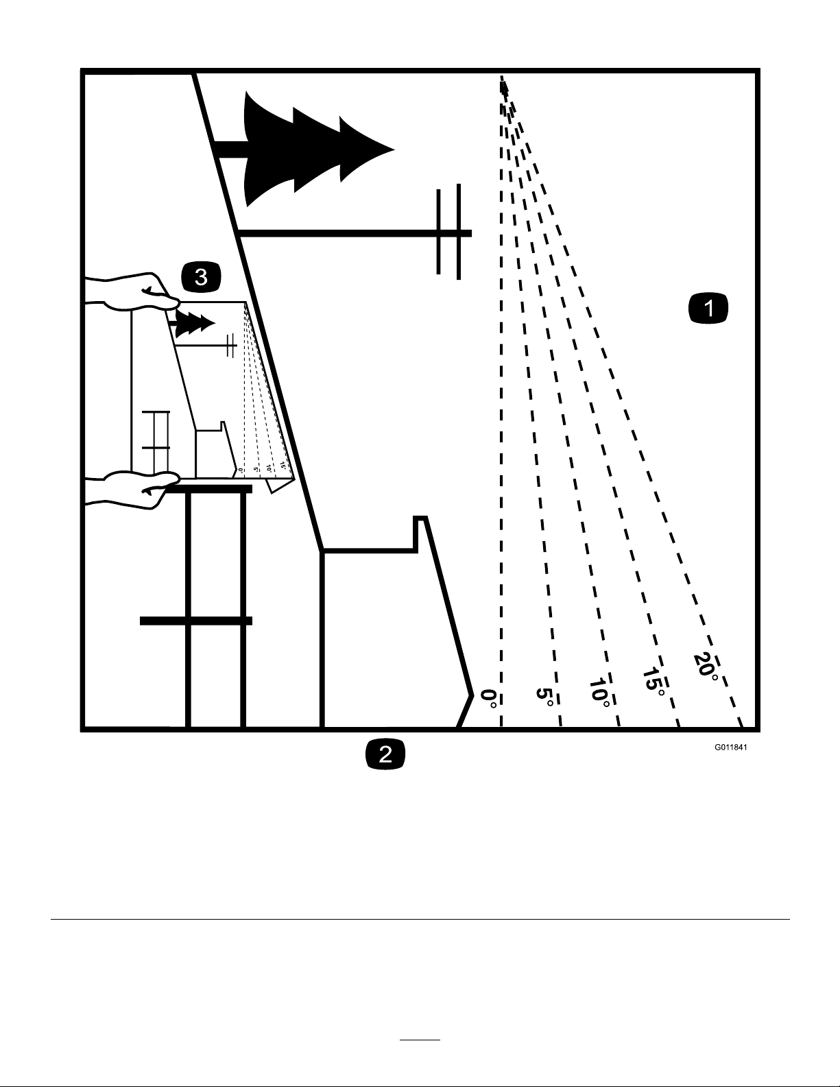
SlopeIndicator
G011841
Figure3
Thispagemaybecopiedforpersonaluse.
1.Themaximumslopeyoucansafelyoperatethemachineonis15degrees.Usetheslopecharttodeterminethedegreeofslope
ofhillsbeforeoperating.Donotoperatethismachineonaslopegreaterthan15degrees.Foldalongtheappropriateline
tomatchtherecommendedslope.
2.Alignthisedgewithaverticalsurface,atree,building,fencepole,etc.
3.Exampleofhowtocompareslopewithfoldededge.
8
Page 9
SafetyandInstructionalDecals
Safetydecalsandinstructionsareeasilyvisibletotheoperatorandarelocatednearanyareaofpotential
danger.Replaceanydecalthatisdamagedorlost.
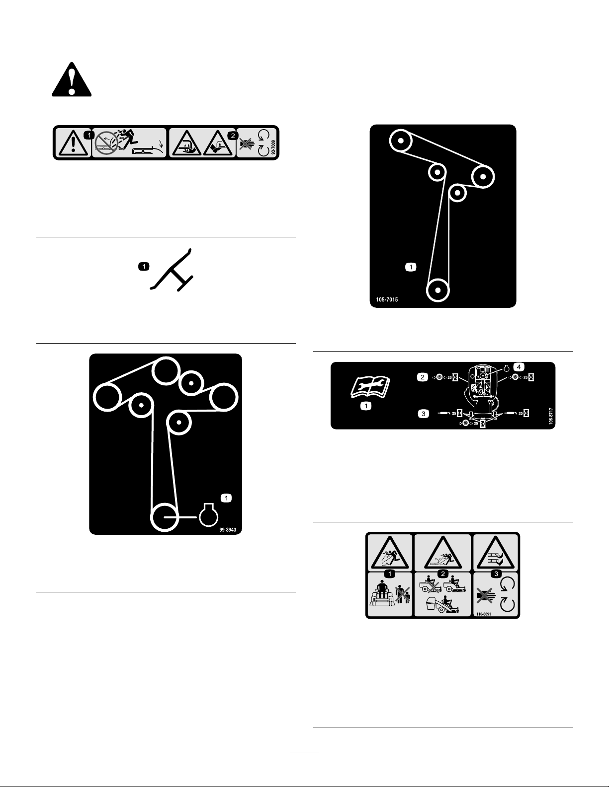
93-7009
1.Warning—don'toperatethemowerwiththedeectorupor
removed;keepthedeectorinplace.
2.Cutting/dismembermenthazardofhandorfoot,mower
blade—stayawayfrommovingparts.
Manufacturer'sMark
1.Indicatesthebladeisidentiedasapartfromtheoriginal
machinemanufacturer.
105-7015
Formodelswith107cm(42inch)decks
106-8717
1.Readtheinstructionsbeforeservicingorperforming
maintenance.
2.Checktirepressureevery25operatinghours.
3.Greaseevery25operatinghours.
4.Engine
99-3943
Formodelswith127cm(50inch)decks
1.Engine
110-6691
1.Thrownobjecthazard—keepbystandersasafedistance
fromthemachine.
2.Thrownobjecthazard,mower—donotoperatewithoutthe
deector,dischargecover,orgrasscollectionsystemin
place.
3.Cutting/dismembermentofhandorfoot—stayawayfrom
movingparts.
9
Page 10
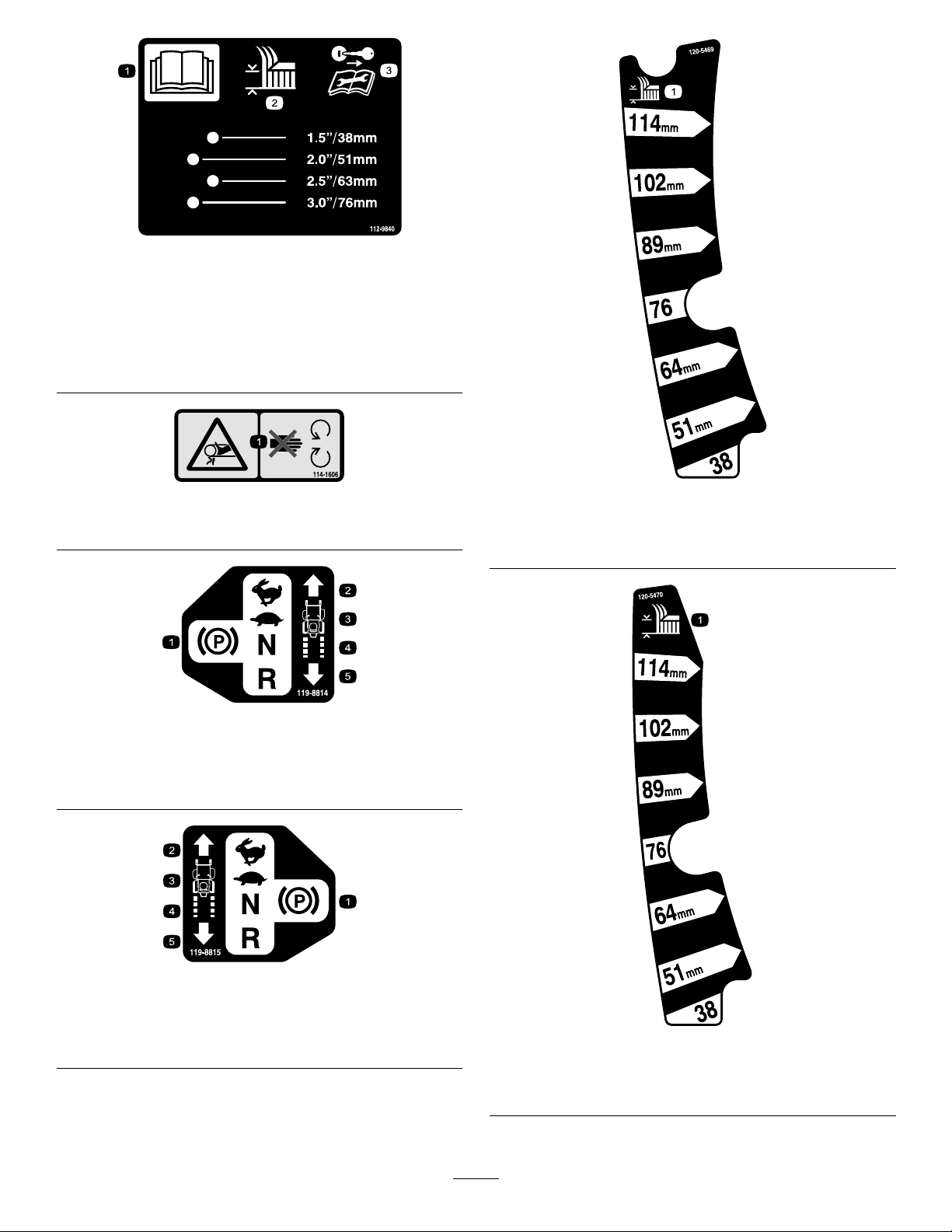
112-9840
Formodelswith127cm(50inch)decks
1.ReadtheOperator's
Manual.
2.Height-of-cut
3.Removetheignitionkey
andreadtheinstructions
beforeservicingor
performingmaintenance.
114-1606
1.Entanglementhazard,belt—keepallguardsinplace.
119-8814
1.Parkingposition4.Neutral
2.Fast5.Reverse
3.Slow
120-5469
Formodelswith107cm(42inch)decks
1.Height-of-cut
119-8815
1.Parkingposition4.Neutral
2.Fast5.Reverse
3.Slow
120-5470
Formodelswith127cm(50inch)decks
1.Height-of-cut
10
Page 11

131-3948
131-4036
1.Bypassleverpositionfor
pushingthemachine
121-2989
2.Bypassleverpositionfor
operatingthemachine
131-3948
1.Maximumdrawbarpull36
kg(80lb)
2.ReadtheOperator's
Manual.
1.Slow
2.Towing
3.Fast
BatterySymbols
Someorallofthesesymbolsareonyourbattery
1.Explosionhazard
2.Nore,opename,or
smoking.
3.Causticliquid/chemical
burnhazard
4.Weareyeprotection9.Flusheyesimmediately
5.ReadtheOperator's
Manual.
6.Keepbystandersasafe
7.Weareyeprotection;
8.Batteryacidcancause
10.Containslead;donot
distancefromthebattery.
explosivegasescan
causeblindnessandother
injuries
blindnessorsevereburns.
withwaterandgetmedical
helpfast.
discard.
11
Page 12
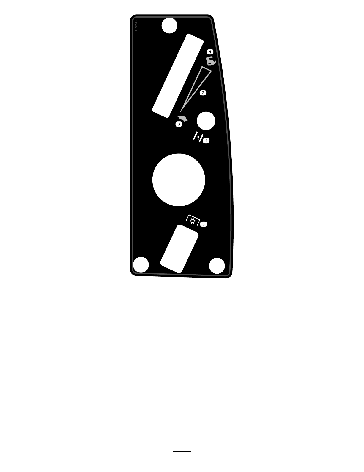
121-0772
1.Fast
2.Continuous-variablesetting5.Powertake-off(PTO),blade-controlswitch
3.Slow
4.Choke
12
Page 13
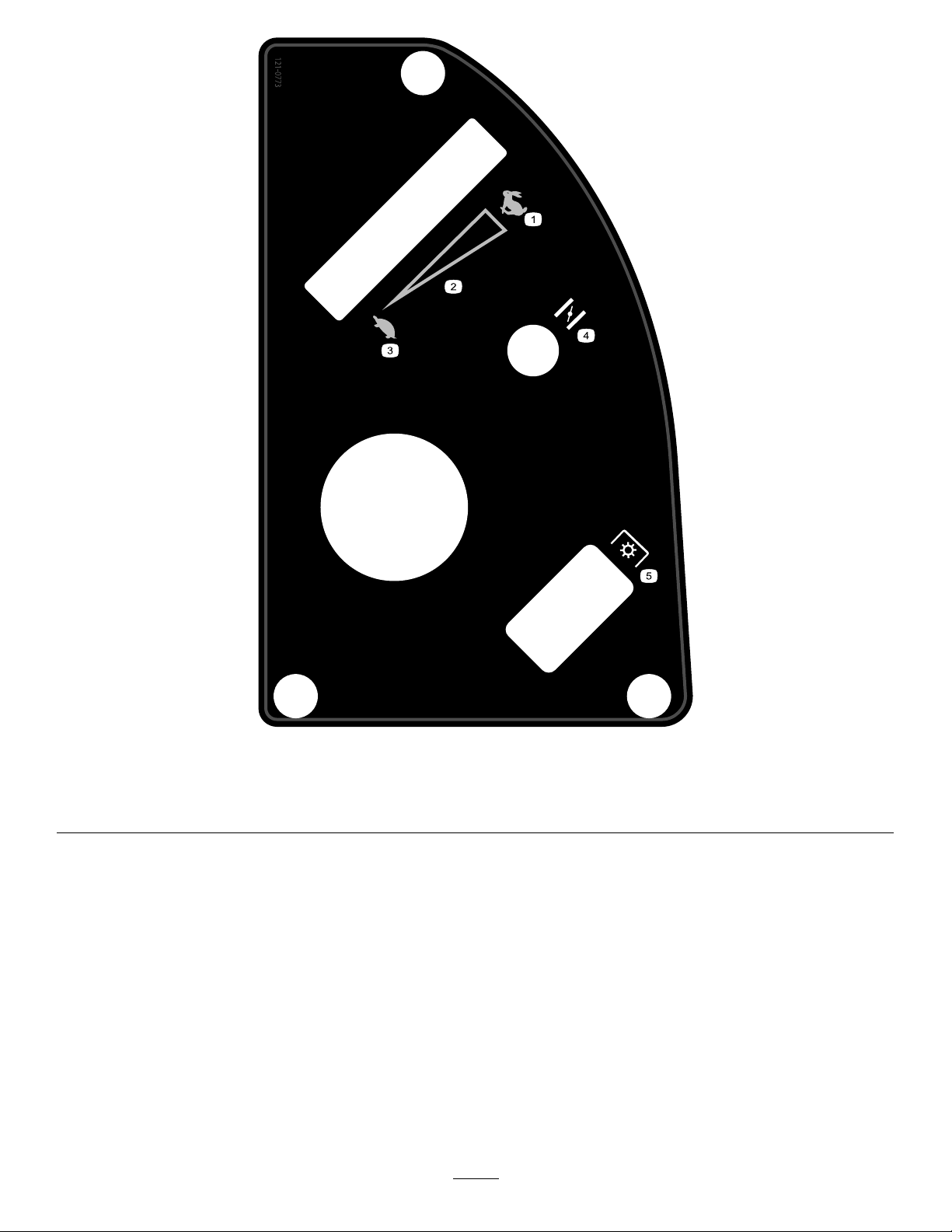
121-0773
1.Fast
2.Continuous-variablesetting5.Powertake-off(PTO),blade-controlswitch
3.Slow
4.Choke
13
Page 14
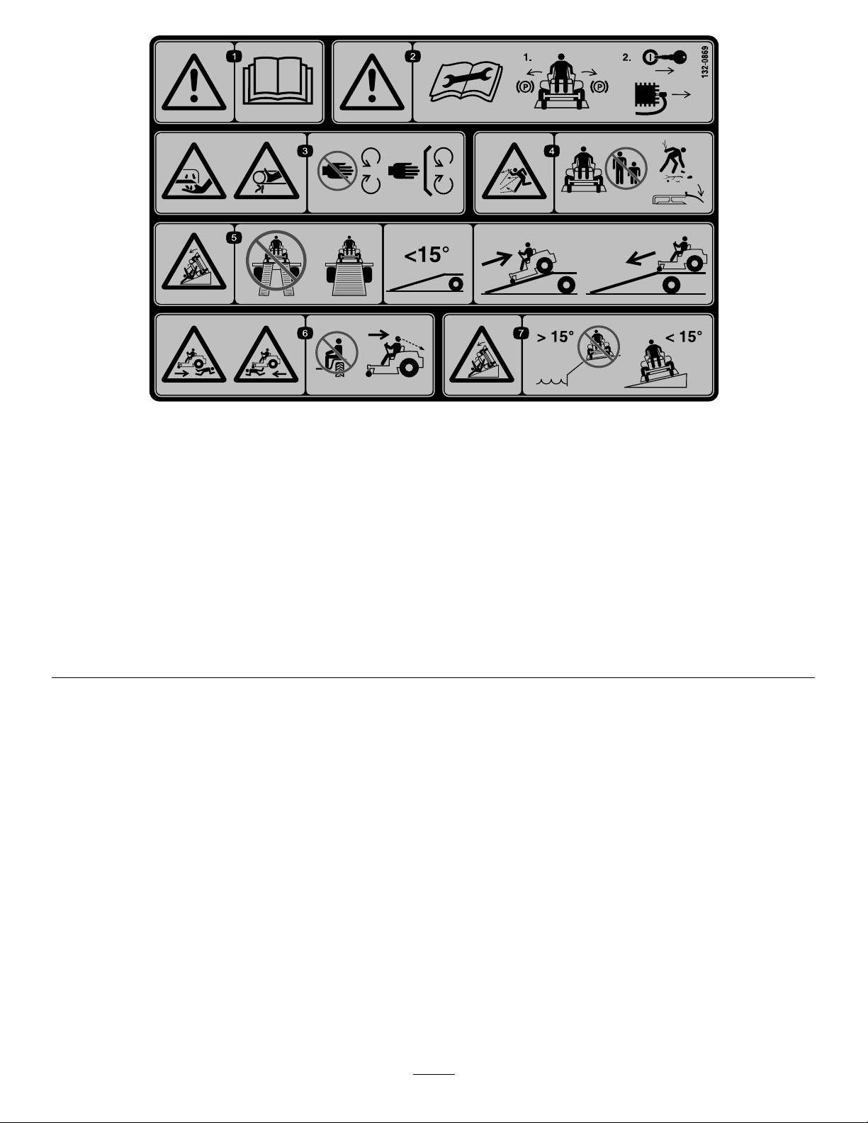
132-0869
1.Warning—readthe
Operator'sManual.
2.Warning—beforeservicing,
engagetheparkingbrake,
removethekeyandthe
sparkplugconnection.
3.Cuttinghazardofhand,
mowerblade;pinching
hazardofhand,belt—keep
handsandfeetawayfrom
movingparts;keepall
guardsandshieldsinplace.
4.Thrownobject
hazard—keepbystanders
awayfromthemachine;
removedebrisfromthe
areabeforemowing;keep
thedeectorshielddown.
5.Ramptipping
hazard—whenloading
ontoatrailer,donotuse
dualramps;onlyusea
singlerampwideenough
forthemachineandthat
hasaninclinelessthan
15degrees;backupthe
ramp(inreverse)anddrive
forwardofftheramp.
6.Bodilyharmhazard—no
riders;lookbehindyou
whenmowinginreverse.
7.Tippinghazardon
slopes—donotuseon
slopesnearopenwater;do
notuseonslopesgreater
than15degrees.
14
Page 15
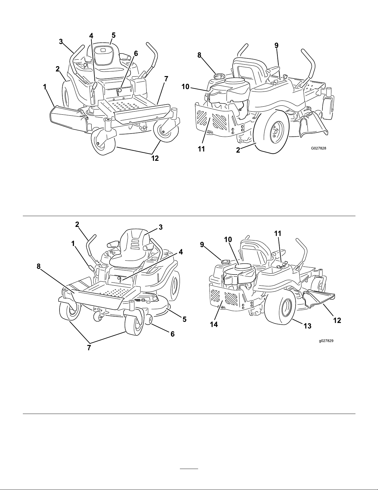
ProductOverview
Figure4
Modelswith107cm(42-inch)decks
1.Deector4.Height-of-cutlever
2.Reardrivewheel
3.Motion-controllevers
5.Operatorseat
6.SmartSpeed™lever9.Controlpanel
7.Footrest10.Engine
8.Fuel-tankcap11.Engineguard
12.Frontcasterwheel
Figure5
Modelswith127cm(50-inch)decks
1.Height-of-cutlever
2.Motion-controllevers6.Anti-scalproller10.Engine14.Engineguard
3.Operatorseat
4.SmartSpeed™lever
5.Mowerdeck9.Fuel-tankcap13.Reardrivewheel
7.Frontcasterwheel
8.Footrest
11.Controlpanel
12.Deector
15
Page 16
Controls
Blade-ControlSwitch(PowerTake-off)
BecomefamiliarwithallofthecontrolsinFigure4,Figure
5,andFigure6beforeyoustarttheengineandoperatethe
machine.
Theblade-controlswitch,representedbyapowertake-off
(PTO)symbol,engagesanddisengagespowertothemower
blades(Figure6).
Motion-ControlLeversandPark
Position
Themotion-controlleversarespeed-sensitivecontrolsof
independent-wheelmotors.Movingaleverforwardor
backwardturnsthewheelonthesamesideforwardorin
reverse;wheelspeedisproportionaltotheamountthelever
ismoved.Movethecontrolleversoutwardfromthecenter
totheparkposition,andexitthemachine(Figure15).Always
positionthemotion-controlleversintotheparkposition
whenyoustopthemachineorleaveitunattended.
SmartSpeed™ControlSystemLever
TheSmartSpeed™Control-Systemlever,locatedbelowthe
operatingposition,givestheoperatorachoicetodrivethe
machineat3speedranges—trim,tow ,andmow(Figure7).
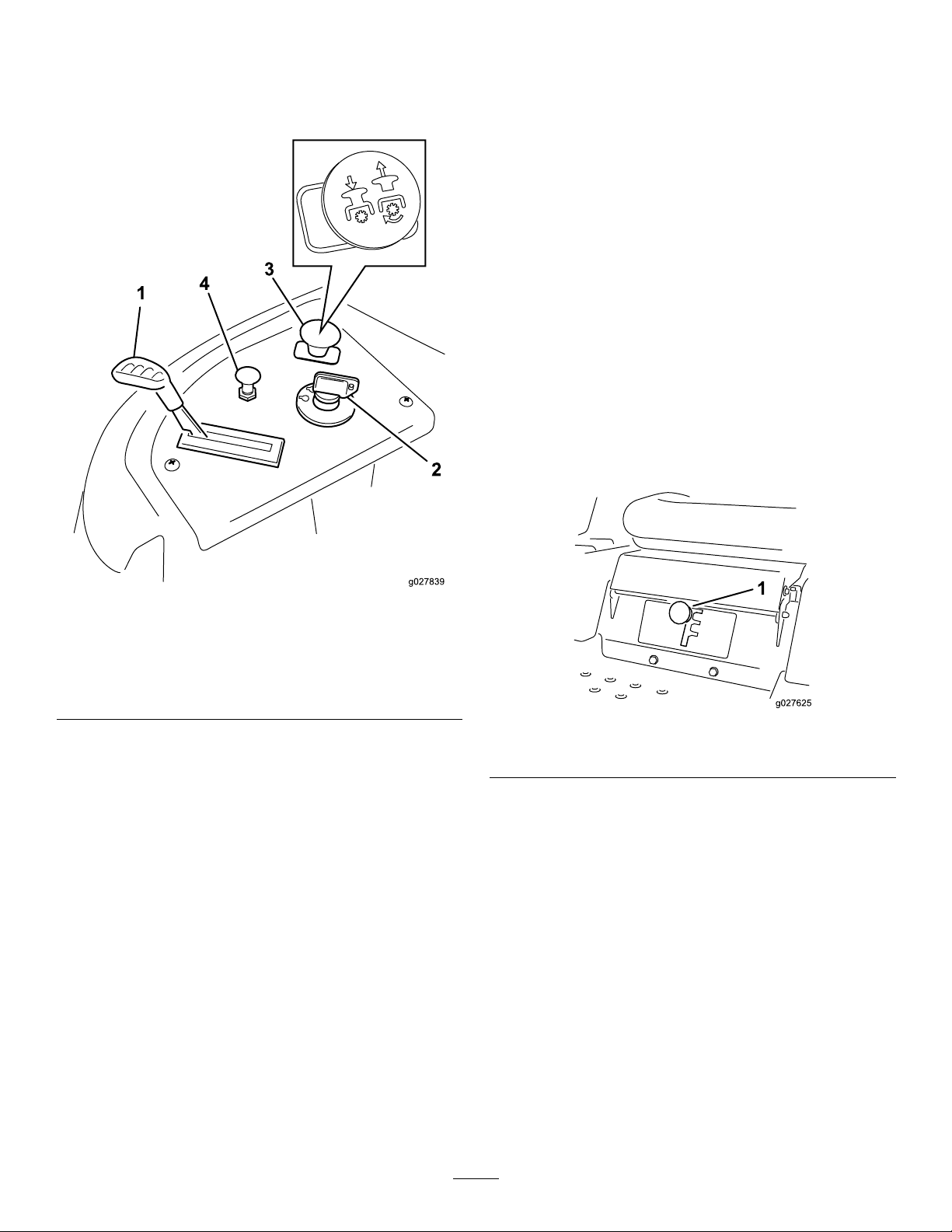
Figure6
ControlPanel
1.Throttle3.Blade-controlswitch
2.Ignitionswitch
(powertake-off)
4.Choke
IgnitionSwitch
Theignitionswitchhas3positions:Off,Run,andStart.The
keywillturntoStartandmovebacktoRunuponrelease.
TurningthekeytotheOffpositionwillstoptheengine;
however,alwaysremovethekeywhenleavingthemachine
topreventsomeonefromaccidentallystartingtheengine
(Figure6).
ThrottleControl
Thethrottlecontrolstheenginespeed,andithasa
continuous-variablesettingfromSlowtoFast(Figure6).
ChokeControl
Figure7
1.Smart-speedlever
Fuel-PresenceWindow
Thefuelwindowlocatedontheleft-handsideofthemachine,
canbeusedtoverifythepresenceofgasolineinthetank
(Figure8).
Pulluponthechokecontroluntilitstopstochoketheengine
(Figure6).Pushdownonthechokecontrolfornormal
engineoperation
16
Page 17

G014521
1
Figure8
1.Fuel-presencewindow
Height-of-CutLever
Theheight-of-cutleverallowstheoperatortolowerand
raisethedeckfromtheseatedposition.Whentheleveris
movedup(towardtheoperator),thedeckisraisedfromthe
ground,andwhenmoveddown(awayfromtheoperator),it
isloweredtowardtheground.Onlyadjusttheheight-of-cut
whilethemachineisnotmoving.RefertoAdjustingthe
Height-of-Cut(page24).
Operation
Note:Determinetheleftandrightsidesofthemachine
fromthenormaloperatingposition.
AddingFuel
•Forbestresults,useonlyclean,fresh(lessthan30days
old),unleadedgasolinewithanoctaneratingof87or
higher((R+M)/2ratingmethod).
•Ethanol:Gasolinewithupto10%ethanol(gasohol)
or15%MTBE(methyltertiarybutylether)byvolume
isacceptable.EthanolandMTBEarenotthesame.
Gasolinewith15%ethanol(E15)byvolumeisnot
approvedforuse.Neverusegasolinethatcontains
morethan10%ethanolbyvolume,suchasE15
(contains15%ethanol),E20(contains20%ethanol),or
E85(containsupto85%ethanol).Usingunapproved
gasolinemaycauseperformanceproblemsand/orengine
damagewhichmaynotbecoveredunderwarranty.
•Donotusegasolinecontainingmethanol.
•Donotstorefueleitherinthefueltankorfuelcontainers
overthewinterunlessafuelstabilizerisused.
•Donotaddoiltogasoline.
DANGER
Incertainconditions,gasolineisextremely
ammableandhighlyexplosive.Areorexplosion
fromgasolinecanburnyouandothersandcan
damageproperty.
•Fillthefueltankoutdoors,inanopenarea,
whentheengineiscold.Wipeupanygasoline
thatspills.
•Neverllthefueltankinsideanenclosedtrailer.
•Donotllthefueltankcompletelyfull.Add
gasolinetothefueltankuntilthelevelis6to13
mm(1/4to1/2inch)belowthebottomofthe
llerneck.Thisemptyspaceinthetankallows
gasolinetoexpand.
•Neversmokewhenhandlinggasoline,andstay
awayfromanopenameorwheregasoline
fumesmaybeignitedbyaspark.
•Storegasolineinanapprovedcontainerand
keepitoutofthereachofchildren.Neverbuy
morethana30-daysupplyofgasoline.
•Donotoperatewithoutentireexhaustsystemin
placeandinproperworkingcondition.
17
Page 18
DANGER
g027243
A
B
E
D
C
Incertainconditionsduringfueling,static
electricitycanbereleasedcausingasparkwhich
canignitethegasolinevapors.Areorexplosion
fromgasolinecanburnyouandothersandcan
damageproperty.
•Alwaysplacegasolinecontainersontheground
awayfromyourvehiclebeforelling.
•Donotllgasolinecontainersinsideavehicleor
onatruckortrailerbedbecauseinteriorcarpets
orplastictruckbedlinersmayinsulatethe
containerandslowthelossofanystaticcharge.
•Whenpractical,removegas-poweredequipment
fromthetruckortrailerandrefueltheequipment
withitswheelsontheground.
•Ifthisisnotpossible,thenrefuelsuch
equipmentonatruckortrailerfromaportable
container,ratherthanfromagasolinedispenser
nozzle.
•Ifagasolinedispensernozzlemustbeused,
keepthenozzleincontactwiththerimofthe
fueltankorcontaineropeningatalltimesuntil
fuelingiscomplete.
Note:Afuelstabilizer/conditionerismosteffective
whenmixedwithfreshgasoline.T ominimizethechance
ofvarnishdepositsinthefuelsystem,usefuelstabilizer
atalltimes.
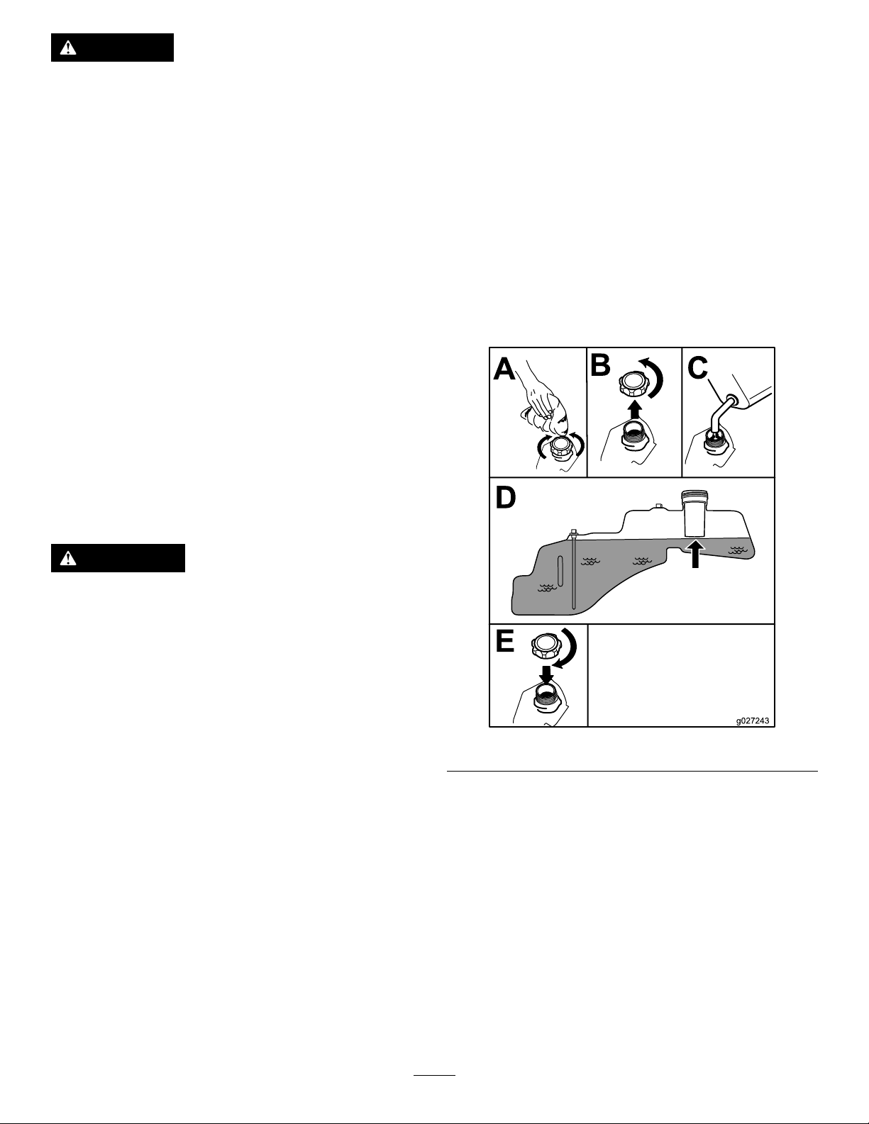
FillingtheFuelTank
Note:Ensurethattheengineisshutoffandthemotion
controlsareintheparkedposition.
Note:Youcanusethefuelwindowtoverifythepresenceof
gasolinebeforellingthetank(Figure9).
Important:Donotoverllfueltank.Fillthefueltank
tothebottomofthellerneck.Theemptyspaceinthe
tankallowsthefueltoexpand.Overllingmayresultin
fuelleakage,damagetotheengine,ordamagetothe
emissionssystem.
WARNING
Gasolineisharmfulorfatalifswallowed.Long-term
exposuretovaporscancauseseriousinjuryand
illness.
•Avoidprolongedbreathingofvapors.
•Keepfaceawayfromnozzleandgastankor
conditionerbottleopening.
•Avoidcontactwithskin;washoffspillagewith
soapandwater.
UsingStabilizer/Conditioner
Useafuelstabilizer/conditionerinthemachinetoprovide
thefollowingbenets:
•Keepsgasolinefreshduringstorageof90daysorless.
Forlongerstorageitisrecommendedthatthefueltank
bedrained.
•Cleanstheenginewhileitruns
•Eliminatesgum-likevarnishbuildupinthefuelsystem,
whichcauseshardstarting
Important:Donotusefueladditivescontaining
methanolorethanol.
Addthecorrectamountofgasstabilizer/conditionerto
thegas.
Figure9
CheckingtheEngine-OilLevel
Beforeyoustarttheengineandusethemachine,check
theoillevelintheenginecrankcase;refertoCheckingthe
Engine-OilLevel(page35).
BreakinginaNewMachine
Newenginestaketimetodevelopfullpower.Mowerdecks
anddrivesystemshavehigherfrictionwhennew,placing
additionalloadontheengine.Allow40to50hoursof
break-intimefornewmachinestodevelopfullpowerand
bestperformance.
18
Page 19

ThinkSafetyFirst
G009027
1
2
CAUTION
OperatingSafety
Pleasecarefullyreadallofthesafetyinstructionsanddecals
inthesafetysection.Knowingthisinformationcouldhelp
you,yourfamily ,pets,orbystandersavoidinjury.
DANGER
Mowingonwetgrassorsteepslopescancause
slidingandlossofcontrol.
Wheelsdroppingoveredgescancauserollovers,
whichmayresultinseriousinjury,death,or
drowning.
Alossoftractionisalossofsteeringcontrol.
Toavoidlossofcontrolandpossibilityofrollover:
•Donotmowneardrop-offsornearwater.
•Donotmowslopesgreaterthan15degrees.
•Reducethespeedanduseextremecautionon
slopes.
•Whenmowingslopes,graduallyworkfrom
lowertohigherareasontheincline.
Thismachineproducessoundlevelsinexcessof85
dBAattheoperatorsearandcancausehearingloss
throughextendedperiodsofexposure.
Wearhearingprotectionwhenoperatingthis
machine.
Theuseofprotectiveequipmentforeyes,ears,hands,feet,
andheadisrecommended.
Figure11
1.Wearsafetyglasses
2.Wearhearingprotection
•Avoidsuddenturnsorrapidspeedchanges.
•Turnup,intoaninclinewhenchanging
directionsonslopes.Turningdowntheslope
reducestraction.
•Attachmentschangethehandlingcharacteristics
ofthemachine.Useextracautionwhenusing
attachmentswiththemachine.
Figure10
1.Safezone—usethe
TimeCutterhere
2.Useawalk-behindmower
and/orhandtrimmernear
drop-offsandwater.
3.Water
19
Page 20

UnderstandingtheSafety-Interlock
g027535
B
C
D
E
A
G
F
System
Note:Theengineshouldstop.
WARNING
Ifsafety-interlockswitchesaredisconnectedor
damaged,themachinecouldoperateunexpectedly
causingpersonalinjury.
•Donottamperwiththeinterlockswitches.
•Checktheoperationoftheinterlockswitches
daily,andreplaceanydamagedswitchesbefore
operatingthemachine.
Thesafety-interlocksystemisdesignedtopreventtheengine
fromstartingunless:
•Thebladesaredisengaged.
•Themotion-controlleversareintheparkposition.
Thesafety-interlocksystemalsoisdesignedtostoptheengine
wheneverthecontrolleversareoutoftheparkpositionand
yourisefromtheseat.
TestingtheSafety-InterlockSystem
Testthesafety-interlocksystembeforeyouusethemachine
eachtime.Ifthesafetysystemdoesnotoperateasdescribed
below,haveanAuthorizedServiceDealerrepairthesafety
systemimmediately.
StartingtheEngine
Note:Awarmorhotenginemaynotrequirechoking
(Figure12).
Important:Donotengagethestarterformorethan
10secondsatatime.Iftheenginefailstostart,allowa
60-secondcool-downperiodbetweenattempts.Failure
tofollowtheseinstructionscandamagethestarter
motor.
1.Whilesittingontheseat,withthecontrolleversinpark
position,andmovetheblade-controlswitchtoOn.
2.Trystartingtheengine;theengineshouldnotcrank.
3.Whilesittingontheseat,movetheblade-control
switchtoOff.
4.Moveeithermotion-controllevertothecenter,
unlockedposition.
5.Trystartingtheengine;theengineshouldnotcrank.
6.Repeatwiththeothermotion-controllever.
7.Whilesittingontheseat,movetheblade-control
switchtoOff,andlockthemotion-controlleversin
theparkposition.
8.Starttheengine.
9.Whiletheengineisrunning,engagetheblade-control
switch,andriseslightlyfromtheseat.
Note:Theengineshouldstop.
10.Whilesittingontheseat,movetheblade-control
switchtoOff,andlockthemotion-controlleversin
theparkposition.
11.Starttheengine.
12.Whiletheengineisrunning,movethemotion-control
leverstothecenter,unlockedposition,engagethe
blade-controlswitch,andriseslightlyfromtheseat.
Figure12
20
Page 21

OperatingtheBlades
g027582
B
C
A
1
g027538
StoppingtheEngine
Theblade-controlswitch,representedbyapowertake-off
(PTO)symbol,engagesanddisengagespowertothemower
blades.Thisswitchcontrolspowertoanyattachmentsthat
drawpowerfromtheengine,includingthemowerdeckand
cuttingblades.
EngagingtheBlades
Important:Donotengagethebladeswhenparkedin
tallgrass;beltorclutchdamagecanoccur.
Note:AlwaysengagethebladeswiththethrottleintheFast
position(Figure13).
1.Disengagethebladesbymovingtheblade-control
switchtoOff(Figure14).
2.MovethethrottlelevertotheSlowposition.
Note:Runitatidlespeedforapproximatelyone
minute.
3.TurntheignitionkeytoOffandremovethekey.
DrivingtheMachine
Drivingthemachinebenetsfromanunderstandingof
whatzero-turn-radiusmowermeans.Thedrivewheelsturn
independently,poweredbyhydraulicmotorsoneachaxle;
henceonesidecanturninreversewhiletheotherturns
forwardcausingthemachinetospinratherthanturn.This
vastlyimprovesthemachinemaneuverabilitybutmayrequire
someadjustmentiftheoperatorisunfamiliar.
WARNING
Themachinecanspinveryrapidly.Theoperator
maylosecontrolofthemachineandcausepersonal
injuryordamagetothemachine.
DisengagingtheBlades
Figure13
•Usecautionwhenmakingturns.
•Slowthemachinedownbeforemakingsharp
turns.
Thethrottlecontrolregulatestheenginespeedasmeasured
inrpm(revolutionsperminute).Placingthethrottlecontrol
intheFastpositioncanbebestforperformance.Formost
applications,operatinginthefull-throttlepositionisdesirable.
Figure14
21
Page 22

Figure15
1.Park(brake)position
2.Center,unlockposition5.Frontofthemachine
3.Forward
4.Backward
UsingtheSmartSpeed
TM
Control
System
TheSmartSpeed
operatingposition(Figure16),givestheoperatorachoice
todrivethemachineat3groundspeedranges—trim,tow ,
andmow .
1.Smartspeedlever
Tochangespeeds,dothefollowing:
1.Movethemotioncontrolleverstoneutralandoutward
totheparkposition.
2.Disengagethebladecontrolswitch
3.Adjustthelevertothedesiredposition.
Thefollowingareonlyrecommendationsforuse.
Adjustmentswillvarybygrasstype,moisturecontent,and
theheightofthegrass.
TM
Control-Systemlever,locatedbelowthe
Figure16
Suggested
uses:
ParkingX
Heavy,wet
grass
TrainingX
BaggingX
MulchingX
Normal
mowing
TransportX
TrimTowMow
X
X
Trim
Thisisthelowestspeed.Thesuggestedusesforthisspeed
areasfollows:
•Parking
•Heavy,wetgrassmowingconditions
•Training
Tow
Thisisthemediumspeed.Thesuggestedusesforthisspeed
areasfollows:
22
Page 23

•Bagging
G008952
G008953
DrivingBackward
•Mulching
Mow
Thisisthefastestspeed.Thesuggestedusesforthisspeed
areasfollows:
•Normalmowing
•Transportingthemachine
DrivingForward
1.Movetheleverstothecenter,unlockedposition.
2.Togoforward,slowlypushthemotion-controllevers
forward(Figure17).
Note:Alwaysusecautionwhenbackingupandturning.
1.Movetheleverstothecenter,unlockedposition.
2.Togobackward,lookbehindyouanddown,asyou
slowlypullthemotion-controlleversrearward(Figure
18).
Figure18
Figure17
Togostraight,applyequalpressuretoboth
motion-controllevers(Figure17).
Toturn,releasepressureonthemotion-controllever
towardthedirectionyouwanttoturn(Figure17).
Thefartheryoumovethemotion-controlleversin
eitherdirection,thefasterthemachinewillmovein
thatdirection.
Tostop,pullthemotion-controlleverstoneutral.
Togostraight,applyequalpressuretoboth
motion-controllevers(Figure18).
Toturn,releasethepressureonthemotion-control
levertowardthedirectionyouwanttoturn.
Tostop,pushthemotion-controlleverstoneutral.
StoppingtheMachine
Tostopthemachine,movethemotion-controlleversto
neutralandoutwardtotheparkposition,disengagethe
blade-controlswitch,movethethrottletotheslowposition,
runitatidlespeedforapproximatelyforoneminute,and
turntheignitionkeytooff.
Note:Remembertoremovethekeyfromtheignitionswitch.
WARNING
Childrenorbystandersmaybeinjuredifthey
moveorattempttooperatethemowerwhileitis
unattended.
Alwaysremovetheignitionkeyandmovethe
motion-controlleversoutwardtotheparkposition
whenleavingthemachineunattended,evenifjust
forafewminutes.
23
Page 24

AdjustingtheHeight-of-Cut
g019929
1
2
3
4
5
Note:Thetransportpositionisthehighestheight-of-cut
positionorcuttingheight(115mm(4.5inches))asshown
inFigure19.
Height-of-cutiscontrolledbytheleverlocatedtotherightof
theoperatingposition(Figure19).
•Upperhole—usethispositionwiththemower
deckinthe63mm(2-1/2inches)andbelowthe
height-of-cutpositions(Figure20).
•Lowerhole—usethispositionwiththemower
deckinthe76mm(3inches)andabovethe
height-of-cutpositions(Figure20).
Figure20
Figure19
AdjustingtheAnti-Scalp Rollers(for107cm(42-inch) MowerDecks)
Wheneveryouchangetheheight-of-cut,itisrecommended
toadjusttheheightoftheanti-scalprollers.
1.Anti-scalproller4.Upperhole—themower
2.Lowerhole—themower
deckinthe76mm(3
inches)andabovethe
height-of-cutpositions
3.Flangenut
deckinthe63mm(2-1/2
inches)andbelowthe
height-of-cutpositions
5.Bolt
AdjustingtheAnti-Scalp Rollers(for127cm(50-inch) MowerDecks)
Wheneveryouchangetheheight-of-cut,itisrecommended
toadjusttheheightoftheanti-scalprollers.
Note:Adjusttheanti-scalprollerssotherollersdonottouch
thegroundinnormal,atmowingareas.
1.Disengagetheblade-controlswitch(PTO),movethe
motion-controlleverstotheneutral-lockposition,and
settheparkingbrake.
2.Stoptheengine,removethekey,andwaitforallmoving
partstostopbeforeleavingtheoperatingposition.
3.Adjusttheanti-scalprollers(Figure21)tomatchthe
closestheight-of-cutposition.
Note:Adjusttheanti-scalprollerssotherollersdonottouch
thegroundinnormal,atmowingareas.
1.Disengagetheblade-controlswitch(PTO),movethe
motion-controlleverstotheneutral-lockposition,and
settheparkingbrake.
2.Stoptheengine,removethekey,andwaitforallmoving
partstostopbeforeleavingtheoperatingposition.
3.Adjusttheanti-scalprollerstooneofthefollowing
positions:
24
Page 25

G010233
1
2
3
4
Figure21
g027249
B
C
A
g027252
B
A
1.Anti-scalproller3.Flangenut
2.Bolt4.Holespacing
PositioningtheSeat
Theseatcanmoveforwardandbackward.Positiontheseat
whereyouhavethebestcontrolofthemachineandaremost
comfortable(Figure22).
AdjustingtheMotion-Control Levers
AdjustingtheHeight
Themotion-controlleverscanbeadjustedhigherorlowerfor
maximumoperatorcomfort(Figure23).
Figure23
Figure22
AdjustingtheTilt
Themotion-controlleverscanbetiltedforeoraftfor
maximumoperatorcomfort.
1.Loosentheupperboltholdingthecontrollevertothe
control-armshaft.
2.Loosenthelowerboltjustenoughtopivotthecontrol
leverforeoraft(Figure23).Tightenbothboltsto
securethecontrolinthenewposition.
3.Repeattheadjustmentfortheoppositecontrollever.
PushingtheMachinebyHand
Important:Alwayspushthemachinebyhand.Donot
towthemachine,becausedamagemayoccur.
Thismachinehasanelectric-brakemechanism,andtopush
themachine,theignitionkeyneedstobeintheRunposition.
Thebatteryneedstobechargedandfunctioningforthe
electricbraketobedisengage.
PushingtheMachine
1.Parkthemachineonalevelsurface,anddisengagethe
blade-controlswitch.
2.Movethemotion-controlleversoutwardtothepark
position,stoptheengine,andwaitforallmovingparts
tostopbeforeleavingtheoperatingposition.
3.Locatethebypassleversontheframeonbothsidesof
theengine.
4.Movethebypassleversforwardthroughthekeyhole
anddowntolocktheminplace(Figure24).
25
Page 26

Note:Ensurethisisdoneforeachlever.
g017303
1 2
3
G009660
1
2
3
4
5
5.Movethemotion-controlleversinwardtotheneutral
positionandturntheignitionkeytotheRunposition.
Note:Donotstartthemachine.
Note:Themachineisnowabletobepushedbyhand.
Figure24
ConvertingtoSideDischarge (formodelswith107cm (42-inch)decks)
Themowerdeckandmowerbladesshippedwiththismachine
weredesignedforoptimummulchingandsidedischarge
performance.
RemovingtheDischargeCoverforthe
SideDischarge
1.Parkthemachineonalevelsurfaceanddisengagethe
blade-controlswitch.
2.Movethemotion-controlleversoutwardtopark
position,stoptheengine,removethekey ,andwaitfor
allmovingpartstostopbeforeleavingtheoperating
position.
3.Removethe2boltsandnutsthatsecurethedischarge
covertothemower(Figure25).
1.Bypass-leverlocations
2.Leverpositionfor
operatingthemachine
6.Whennished,ensurethatthekeyhasbeenreturnedto
theStoppositiontoavoiddrainingthebatterycharge.
Note:Ifthemachinefailstomove,theelectricbrakemay
stillbeengaged.Ifnecessary,theelectricbrakecanbereleased
manually;refertoReleasingtheElectricBrake(page41).
3.Leverpositionforpushing
themachine
OperatingtheMachine
Movethebypassleversrearwardthroughthekeyholeand
downtolocktheminplaceasshowninFigure24.
Note:Ensurethisisdoneforeachlever.
Figure25
1.Capnut(1/4inch)
2.Dischargecover5.Removethecover
3.Bolt(1/4x2-1/2inches)
4.Removethedischargecover.
5.Liftupthegrassdeector,andlocatethelocknuton
thedeectorpivotrod.
6.Removetheexistingthinnut(3/8inch).
7.Installthecutoffbafetotheexposedpivotrod
(Figure26).
4.Rotatethecoverup
Note:Usetheexistingthinnut(3/8inch)tosecure
thebafetothemower.
Note:Thecutoffbafewasshippedwiththemachine
asaloosepart.
26
Page 27

G005667
1
2
3
Figure26
1.Pivotrod
2.Cutoffbafe(originally
shippedwiththemachine)
8.Torquethefastenerto7to9N-m(14to18ft-lb).
9.Lowerthegrassdeectoroverthedischargeopening
Important:Ensurethatthemowerhasahinged
grassdeectorthatdispersesclippingstotheside
anddowntowardtheturf,whileinside-discharge
mode.
3.Existingthinnut(3/8inch)
InstallingtheDischargeCoverfor
Mulching
1.Parkthemachineonalevelsurfaceanddisengagethe
blade-controlswitch.
2.Movethemotion-controlleversoutwardtothepark
position,stoptheengine,removethekey ,andwait
forallthemovingpartstostopbeforeleavingthe
operatingposition.
3.Removethecutoffbafefromthemowerdeck(Figure
26).
4.Liftthegrassdeectorandslidethetabsontopofthe
dischargecoverunderthegrassdeectorretainingrod.
5.Rotatethedischargecoverdownovertheopening,and
ontothelowerlipofthemower(Figure27).
Figure27
1.Dischargecover
2.Capnut(1/4inch)
6.Securethedischargecovertothelowerlipofthe
mowerwith2bolts(1/4x2-1/2inches)and2capnuts
(1/4inch)asshowninFigure27.
Note:Donotovertightenthenuts;thiscoulddistort
thecoverandcausebladecontact.
3.Bolt(1/4x2-1/2inches)
ConvertingtoSideDischarge (formodelswith127cm (50-inch)decks)
Themowerdeckandmowerbladesshippedwiththismachine
weredesignedforoptimummulchingandsidedischarge
performance.
RemovingtheRightBafeforSide
Discharge
1.Parkthemachineonalevelsurfaceanddisengagethe
blade-controlswitch.
2.Movethemotion-controlleversoutwardtothepark
position,stoptheengine,removethekey ,andwaitfor
allmovingpartstostopbeforeleavingtheoperating
position.
3.Removetherightmowerblade;refertoRemovingthe
27
Blades(page44).
Page 28

4.Removethe2knobsandcurvedwashersthatsecure
G015321
1
2
3
therightbafetothemower(Figure28).
Figure28
1.Knob
2.Curvedwasher
3.Bafestudcomingthrough
themower
5.Removetherightbafeandlowerthegrassdeector
overthedischargeopeningasshowninFigure28and
Figure29.
WARNING
Openholesinthemowerexposeyouand
otherstothrowndebriswhichcancause
severeinjury.
•Neveroperatethemowerwithouthardware
mountedinallholesinthemowerhousing.
•Installthehardwareinthemountingholes
whenyouremovethemulchingbafe.
7.Installtherightmowerblade;refertoRemovingthe
Blades(page44).
8.Liftupthegrassdeector.Install2bolts(5/16x3/4
inch)tothetwoholesalongthedeckcutout.
9.Installthecutoffbafetothemowerdeck(Figure30).
Note:Usethe2locknuts(5/16inch)tosecurethe
bafetothemowerdeck.
Note:Thecutoffbafewasshippedwiththemachine
asaloosepart.
Figure30
1.Bolt(5/16x3/4inch)3.Locknut(5/16inch)
2.Cutoffbafe
10.Torquethefastenersto7to9N-m(14to18ft-lb).
11.Lowerthegrassdeectoroverthedischargeopening.
Important:Ensurethatthemowerhasahinged
grassdeectorthatdispersesclippingstotheside
anddowntowardtheturf,whileinsidedischarge
mode.
1.Rightbafe
2.Curvedwasherandknob
Figure29
3.Dischargeopening
6.Installfastenersintotheholesinthetopofthemower
topreventyingdebris.
28
Page 29

InstallingtheRightBafeforMulching
1.Parkthemachineonalevelsurfaceanddisengagethe
blade-controlswitch.
2.Movethemotion-controlleversoutwardtothepark
position,stoptheengine,removethekey ,andwaitfor
allmovingpartstostopbeforeleavingtheoperating
position.
3.Removethecutoffbafefromthemowerdeck(Figure
30).
4.Removetherightmowerblade;refertoRemovingthe
Blades(page44).
Figure31
5.Slidetherightbafeunderthemowerdeck,andsecure
itusing2knobsandthecurvedwashers(cuppedside
facingthemower)asshowninFigure28andFigure29.
Important:Ensurethatthetabonthefarright
sideoftherightbafeisoutsideofthemowerand
isushwiththemowerwall.
6.Installtherightmowerblade;refertoRemovingthe
Blades(page44).
TransportingtheMachine
Useaheavy-dutytrailerortrucktotransportthemachine.
Ensurethatthetrailerortruckhasallnecessarybrakes,
lighting,andmarkingasrequiredbylaw .Pleasecarefullyread
allthesafetyinstructions.Knowingthisinformationcould
helpyou,yourfamily,pets,orbystandersavoidinjury.
WARNING
Drivingonthestreetorroadwaywithoutturn
signals,lights,reectivemarkings,oraslow
movingvehicleemblemisdangerousandcanlead
toaccidentscausingpersonalinjury.
Donotdrivemachineonapublicstreetorroadway.
Totransportthemachine:
1.Ifusingatrailer,connectittothetowingvehicleand
connectthesafetychains.
LoadingtheMachine
Useextremecautionwhenloadingorunloadingmachines
ontoatraileroratruck.Useafull-widthrampthatiswider
thanthemachineforthisprocedure.Backuprampsand
driveforwarddownramps(Figure32).
Figure32
1.Backupramps
Important:Donotusenarrowindividualrampsfor
eachsideofthemachine.
Ensuretherampislongenoughsothattheanglewiththe
grounddoesnotexceed15degrees(Figure33).Onat
ground,thisrequiresaramptobeatleastfourtimes(4X)as
longastheheightofthetrailerortruckbedtotheground.A
steeperanglemaycausemowercomponentstogetcaughtas
theunitmovesfromtheramptothetrailerortruck.Steeper
anglesmayalsocausethemachinetotiporlosecontrol.If
loadingonornearaslope,positionthetrailerortrucksothat
itisonthedownsideoftheslopeandtherampextendsup
theslope.Thiswillminimizetherampangle.
2.Driveforwarddownramps
2.Ifapplicable,connectthetrailerbrakes.
3.Loadthemachineontothetrailerortruck.
4.Stoptheengine,removethekey,setthebrake,and
closethefuelvalve.
5.Tiedownthemachinenearthefrontcasterwheelsand
therearbumper(Figure31).
29
Page 30

WARNING
g027996
5
1
2
6
Loadingamachineontoatrailerortruckincreases
thepossibilityoftip-overandcouldcauseserious
injuryordeath.
•Useextremecautionwhenoperatingamachine
onaramp.
•Useonlyafull-widthramp;donotuseindividual
rampsforeachsideofthemachine.
•Donotexceeda15-degreeanglebetweenthe
rampandthegroundorbetweentherampand
thetrailerortruck.
•Ensurethelengthoframpisatleastfourtimes
(4X)aslongastheheightofthetrailerortruck
bedtotheground.Thiswillensurethatramp
angledoesnotexceed15degreesonatground.
•Backuprampsanddriveforwarddownramps.
•Avoidsuddenaccelerationordecelerationwhile
drivingthemachineonarampasthiscould
causealossofcontroloratip-oversituation.
Figure33
1.Full-widthrampinstowed
position
2.Sideviewoffull-width
rampinloadingposition
3.Notgreaterthan
15degrees
4.Rampisatleastfourtimes
(4X)aslongastheheight
ofthetrailerortruckbed
totheground
5.H=heightofthetraileror
truckbedtotheground
6.Trailer
30
Page 31

OperatingTips
UsingtheFastThrottleSetting
Forbestmowingandmaximumaircirculation,operate
theengineattheFastthrottleposition.Airisrequiredto
thoroughlycutgrassclippings,sodonotsettheheight-of-cut
solowastototallysurroundthemowerbyuncutgrass.
Alwaystrytohaveonesideofthemowerfreefromuncut
grass,whichallowsairtobedrawnintothemower.
UsingtheSmartSpeed™Control
System
TheSmartSpeed™Control-Systemlever,locatedbelowthe
operatingposition,givestheoperatorachoicetodrivethe
machineat3speedranges—trim,tow,andmow .Anoperator
canbenetfromthetrimspeedsettingwhenmaneuvering
themachineintightspacesoroperatingarounddelicate
landscapes.Thetrimsettingcanalsobeusedtooperatethe
machineatahighthrottlesettingandbladespeed,whilestill
beingabletoreducethegroundspeedtoincreasethequality
ofcut.
CuttingLongGrass
Ifthegrassiseverallowedtogrowslightlylongerthan
normal,orifitcontainsahighdegreeofmoisture,raisethe
cuttingheighthigherthanusualandcutthegrassatthis
setting.Thencutthegrassagainusingthelower,normal
setting.
Stopping
Ifthemachine'sforwardmotionmustbestoppedwhile
mowing,aclumpofgrassclippingsmaydropontoyour
lawn.Toavoidthis,moveontoapreviouslycutareawiththe
bladesengagedoryoucandisengagethemowerdeckwhile
movingforward.
KeepingtheUndersideoftheMower
Clean
Cleanclippingsanddirtfromtheundersideofthemower
aftereachuse.Ifgrassanddirtbuildupinsidethemower,
cuttingqualitywilleventuallybecomeunsatisfactory.
CuttingaLawnfortheFirstTime
Cutgrassslightlylongerthannormaltoensurethatthe
cuttingheightofthemowerdoesnotscalpanyuneven
ground.However,thecuttingheightusedinthepastis
generallythebestonetouse.Whencuttinggrasslongerthan
15cm(6inches)tall,youmaywanttocutthelawntwiceto
ensureanacceptablequalityofcut.
Cutting1/3oftheGrassBlade
Itisbesttocutonlyabout1/3ofthegrassblade.Cutting
morethanthatisnotrecommendedunlessgrassissparse,or
itislatefallwhengrassgrowsmoreslowly.
AlternatingtheMowingDirection
Alternatethemowingdirectiontokeepthegrassstanding
straight.Thisalsohelpsdisperseclippingswhichenhances
decompositionandfertilization.
MowingatCorrectIntervals
Normally,mowevery4days.But,remember,grassgrowsat
differentratesatdifferenttimes.Sotomaintainthesame
cuttingheight,whichisagoodpractice,andmowmoreoften
inearlyspring.Asthegrassgrowthrateslowsinmidsummer,
mowlessfrequently.Ifyoucannotmowforanextended
period,rstmowatahighcuttingheight,thenmowagain2
dayslateratalowerheightsetting.
MaintainingtheBlade(s)
Maintainasharpbladethroughoutthecuttingseasonbecause
asharpbladecutscleanlywithouttearingorshreddingthe
grassblades.Tearingandshreddingturnsgrassbrownat
theedges,whichslowsgrowthandincreasesthechanceof
disease.Checkthemowerbladesaftereachuseforsharpness,
andforanywearordamage.Filedownanynicksandsharpen
thebladesasnecessary.Ifabladeisdamagedorworn,replace
itimmediatelywithagenuineTororeplacementblade.
AvoidingCuttingTooLow
Ifthecuttingwidthofthemoweriswiderthanthemower
youpreviouslyused,raisethecuttingheighttoensurethat
uneventurfisnotcuttooshort.
31
Page 32

Maintenance
Note:Determinetheleftandrightsidesofthemachinefromthenormaloperatingposition.
RecommendedMaintenanceSchedule(s)
MaintenanceService
Interval
Aftertherst8hours
Beforeeachuseordaily
Aftereachuse
Every25hours
Every100hours
Every200hours
Beforestorage
MaintenanceProcedure
•Changetheengineoil.
•Checkthesafety-interlocksystem.
•Checktheengineoillevel.
•Cleantheair-intakescreen.
•Checkthecuttingblades.
•Inspectthegrassdeectorfordamage.
•Cleanthemower-deckhousing.
•Greaseallthelubricationpoints.
•Checktirepressure.
•Checkthebeltsforwearorcracks.
•Servicethepaperelement(moreoftenindusty ,dirtyconditions).
•Changetheengineoil(moreoftenindusty,dirtyconditions).
•Checkthesparkplug(s).
•Replacethein-linefuellter
•Replacethepaperelement(moreoftenindusty ,dirtyconditions).
•Changetheoillter(moreoftenindusty,dirtyconditions).
•Chargethebatteryanddisconnectbatterycables.
•Performallmaintenanceprocedureslistedabovebeforestorage.
•Paintanychippedsurfaces.
Important:Refertoyourengineoperator'smanualforadditionalmaintenanceprocedures.
CAUTION
Ifyouleavethekeyintheignitionswitch,someonecouldaccidentlystarttheengineandseriouslyinjure
youorotherbystanders.
Removethekeyfromtheignitionanddisconnectthewirefromthesparkplugbeforeyoudoany
maintenance.Setthewireasidesothatitdoesnotaccidentallycontactthesparkplug.
32
Page 33

Premaintenance
1
G014522
Lubrication
Procedures
GreasingtheBearings
RaisingtheSeat
Makesurethatthemotion-controlleversarelockedinthe
parkposition,andlifttheseatforward.
Thefollowingcomponentscanbeaccessedbyraisingtheseat:
•Serialplate
•Servicedecal
•Seat-adjustmentbolts
•Fuellter
•Batteryandbatterycables
ReleasingtheMower-Deck Curtain
Loosenthe2bottomboltsofthecurtaintogainaccesstothe
topofthemowerdeck(Figure34).
ServiceInterval:Every25hours—Greaseallthelubrication
points.
GreaseType:No.2generalpurpose,lithium-basedgrease
1.Parkthemachineonalevelsurface,anddisengagethe
blade-controlswitch.
2.Movethemotion-controlleversoutwardtothepark
position,stoptheengine,removethekey ,andwaitfor
allmovingpartstostopbeforeleavingtheoperating
position.
3.Cleanthegreasettings(Figure35andFigure36)with
arag.
Note:Makesuretoscrapeanypaintoffthefrontof
thetting(s).
Figure34
1.Bottombolt
Note:Alwaystightentheboltstoconnectthecurtainafter
maintenance.
2.Curtain
Figure35
1.Frontcastertire
Figure36
Locatedontheseat-panunderside
1.Readtheinstructions
beforeservicingor
performingmaintenance
2.Checkthetirepressure
every25operatinghours
4.Connectagreaseguntoeachtting(Figure35and
Figure36).
33
3.Greaseevery25operating
hours
4.Engine
Page 34

5.Pumpgreaseintothettingsuntilgreasebeginsto
G014908
1
2
3
oozeoutofthebearings.
EngineMaintenance
ServicingtheAirCleaner
Note:Servicetheaircleanermorefrequently(everyfew
hours)ifoperatingconditionsareextremelydustyorsandy.
RemovingtheElement
1.Parkthemachineonalevelsurfaceanddisengagethe
blade-controlswitch(PTO).
2.Movethemotion-controlleverstothebrakeposition,
stoptheengine,removethekey ,andwaitforallmoving
partstostopbeforeleavingtheoperatingposition.
3.Cleanaroundtheair-cleanercovertopreventdirtfrom
gettingintotheengineandcausingdamage.
4.Liftthecoverandremovethehoseclampsecuringthe
air-cleanerassemblytotheengine(Figure37).
5.Loosenthehoseclampandremovethepaperelement
(Figure37).
Figure37
1.Cover
2.Paperelement
3.Hoseclamp
CleaningthePaperElement
ServiceInterval:Every100hours—Servicethepaper
Every200hours/Yearly(whichevercomes
rst)—Replacethepaperelement(moreoftenin
dusty,dirtyconditions).
1.Lightlytaptheelementonaatsurfacetoremovedust
anddirt.
2.Inspecttheelementfortears,anoilylm,anddamage
totheseal.
34
element(moreoftenindusty,dirty
conditions).
Page 35

Important:Donotcleanthepaperelementwith
g017470
SAE V iscosity Grades
SAE 40
SAE 30
SAE 10W– 30/ SAE 10W– 40
-20 0 20 32 40 60 80 100
-30 -20 -10 0 10 20 30 40
°F
°C
STARTING TEMPERA TURE RANGE ANTICIPATED BEFORE NEXT OIL CHANGE
SAE 5W– 20
B
A
C
D
E
G027659
F
G
H
I J
pressurizedairorliquids,suchassolvent,gas,
orkerosene.Replacethepaperelementifitis
damagedorcannotbecleanedthoroughly.
ServicingtheEngineOil
OilType:Detergentoil(APIserviceSF,SG,SH,SJ,orSL)
CrankcaseCapacity:
Model
74656
74660
Viscosity:Seethetablebelow.
Note:Usingmultigradeoils(5W-20,10W -30,and10W-40)
willincreaseoilconsumption.Checkoillevelmorefrequently
whenusingthem.
OillternotremovedOillterremoved
1.5L(50.7oz)1.7L(57.5oz)
1.8L(60.9oz)2.1L(71oz)
Figure38
CheckingtheEngine-OilLevel
ServiceInterval:Beforeeachuseordaily
Note:Checktheoilwhentheengineiscold.
WARNING
Contactwithhotsurfacesmaycausepersonal
injury.
Keephands,feet,face,clothingandotherbody
partsawaythemuferandotherhotsurfaces.
Important:Donotoverllthecrankcasewithoiland
runtheengine;enginedamagemayresult.
1.Parkthemachineonalevelsurface.
2.Disengagetheblade-controlswitch(PTO).
3.Stoptheengine,waitforallmovingpartstostop,and
removethekeybeforeleavingtheoperatingposition.
4.Checktheengine-oillevel(Figure39).
Figure39
35
Page 36

ChangingtheEngineOil
A B
C
D
F
E
G027539
B
A
C
D
E
F
g027660
ServiceInterval:Aftertherst8hours—Changetheengine
oil.
Every100hours—Changetheengineoil(moreoften
industy ,dirtyconditions).
Note:Disposeoftheusedoilatarecyclingcenter.
1.Parkthemachinesothatthedrainsideisslightly
lowerthantheoppositesidetoassuretheoildrains
completely.
2.DisengagethePTO ,movethemotion-controlleversto
theneutral-lockedposition,andsettheparkingbrake.
3.Stoptheengine,removethekey,andwaitforall
movingpartstostopbeforeleavingtheoperating
position(Figure40).
4.Slowlypourapproximately80%ofthespeciedoil
intothellertubeandslowlyaddtheadditionaloilto
bringittotheFullmark(Figure41).
Figure41
Figure40
36
Page 37

ChangingtheEngine-OilFilter
B
A
C D
E
F
3/4
g027477
B
A
g027478
B
A
g027479
RemovingtheSparkPlug
ServiceInterval:Every200hours—Changetheoillter
(moreoftenindusty,dirtyconditions).
Note:Changetheengine-oilltermorefrequentlywhen
operatingconditionsareextremelydustyorsandy.
1.Draintheoilfromtheengine;refertoChangingthe
EngineOil(page36).
2.Changetheengineoillter(Figure42).
1.Disengagetheblade-controlswitch(PTO).
2.Stoptheengine,waitforallmovingpartstostop,and
removethekeybeforeleavingtheoperatingposition.
3.Removethesparkplug(Figure44).
Figure43
CheckingtheSparkPlug
Important:Donotcleanthesparkplug.Always
replacethesparkplugwhenithasablackcoating,worn
electrodes,anoilylm,orcracks.
Note:Ifyouseelightbrownorgrayontheinsulator,the
engineisoperatingproperly.Ablackcoatingontheinsulator
usuallymeansthattheaircleanerisdirty.
Note:Ensurethattheoil-ltergaskettouchesthe
engineandthenanextra3/4turniscompleted.
3.Fillthecrankcasewiththepropertypeofnewoil;refer
toChangingtheEngineOil(page36).
ServicingtheSparkPlug
ServiceInterval:Every100hours—Checkthesparkplug(s).
Makesuretheairgapbetweenthecenterandsideelectrodes
iscorrectbeforeinstallingthesparkplug.Useaspark-plug
wrenchforremovingandinstallingthesparkplug(s)anda
gappingtool/feelergaugetocheckandadjusttheairgap.
Installanewsparkplug(s)ifnecessary.
Setthegapto0.76mm(0.030).
Figure42
Figure44
Type:NGKBPR4ES(orequivalent)
AirGap:0.76mm(0.03inch)
37
Page 38

InstallingtheSparkPlug
B
A
16 ft-lb
22 N-m
g027661
C
D
Tightenthesparkplugto22N-m(16ft-lb).
FuelSystem
Maintenance
DANGER
Incertainconditions,gasolineisextremely
ammableandhighlyexplosive.Areorexplosion
fromgasolinecanburnyou,others,andcan
damageproperty.
•Performanyfuel-relatedmaintenancewhenthe
engineiscold.Dothisoutdoorsinanopenarea.
Wipeupanygasolinethatspills.
•Neversmokewhendraininggasoline,andstay
awayfromanopenameorwhereasparkmay
ignitethegasolinefumes.
ReplacingtheIn-LineFuel
Figure45
CleaningtheCoolingSystem
Cleantheair-intakescreenfromgrassanddebrisbeforeeach
use.
1.Disengagetheblade-controlswitch,movethecontrol
leverstotheneutral-lockedposition,andapplythe
parkingbrake.
2.Stoptheengine,removethekey,andwaitforallmoving
partstostopbeforeleavingtheoperatingposition.
3.Removetheair-intakescreen,theair-cleanercover,and
thefanhousing.
4.Cleandebrisandgrassfromtheparts.
5.Installtheair-intakescreen,air-cleanercover,andthe
fanhousing.
Filter
ServiceInterval:Every100hours—Replacethein-linefuel
lter
Neverinstalladirtylterifitisremovedfromthefuelline.
1.Parkthemachineonalevelsurfaceanddisengagethe
blade-controlswitch.
2.Movethemotion-controlleversoutwardtothepark
position,stoptheengine,removethekey ,andwaitfor
allmovingpartstostopbeforeleavingtheoperating
position.
3.Replacethein-linefuellter(Figure46).
38
Page 39

g027590
B
A
C
D
g027518
ElectricalSystem
Maintenance
WARNING
CALIFORNIA
Proposition65Warning
Batteryposts,terminals,andrelated
accessoriescontainleadandleadcompounds,
chemicalsknowntotheStateofCalifornia
tocausecancerandreproductiveharm.
Washhandsafterhandling.
ChargingtheBattery
RemovingtheBattery
WARNING
Batteryterminalsormetaltoolscouldshortagainst
metalmachinecomponentscausingsparks.Sparks
cancausethebatterygassestoexplode,resulting
inpersonalinjury.
Figure46
•Whenremovingorinstallingthebattery,donot
allowthebatteryterminalstotouchanymetal
partsofthemachine.
•Donotallowmetaltoolstoshortbetween
thebatteryterminalsandmetalpartsofthe
machine.
1.Parkthemachineonalevelsurfaceanddisengagethe
blade-controlswitch.
2.Movethemotion-controlleversoutwardtothepark
position,stoptheengine,removethekey ,andwaitfor
allmovingpartstostopbeforeleavingtheoperating
position.
3.Raisetheseattoaccessthebattery.
4.Disconnectthenegative(black)groundcablefromthe
batterypost(Figure47).
Note:Retainallfasteners.
39
Page 40

WARNING
G005072
1
2
3
4
5
6
7
Incorrectbattery-cableroutingcoulddamage
themachineandcablescausingsparks.
Sparkscancausethebatterygassesto
explode,resultinginpersonalinjury.
ChargingtheBattery
ServiceInterval:Beforestorage—Chargethebatteryand
disconnectbatterycables.
1.Removethebatteryfromthechassis;refertoRemoving
theBattery(page39).
•Alwaysdisconnectthenegative(black)
batterycablebeforedisconnectingthe
positive(red)cable.
•Alwaysconnectthepositive(red)battery
cablebeforeconnectingthenegative
(black)cable.
5.Slidetherubbercoverupthepositive(red)cable.
6.Disconnectthepositive(red)cablefromthebattery
post(Figure47).
Note:Retainallfasteners.
7.Removethebatteryhold-down(Figure47),andliftthe
batteryfromthebatterytray .
2.Chargethebatteryforaminimumof1hourat6to
10amps.
Note:Donotoverchargethebattery.
3.Whenthebatteryisfullycharged,unplugthecharger
fromtheelectricaloutlet,thendisconnectthecharger
leadsfromthebatteryposts(Figure48).
Figure48
1.Positive(+)batterypost3.Red(+)chargerlead
2.Negative(–)batterypost4.Black(–)chargerlead
1.Battery
2.Positive(+)batterypost
3.Bolt,washer,andnut7.Batteryhold-down
4.Terminalboot
InstallingtheBattery
1.Positionthebatteryinthetray(Figure47).
2.Usingthefastenerspreviouslyremoved,installthe
positive(red)batterycabletothepositive(+)battery
terminal.
3.Usingthefastenerspreviouslyremoved,installthe
negativebatterycabletothenegative(-)battery
Figure47
5.Negative(–)batterypost
6.Wingnut,washer,andbolt
terminal.
4.Slidetheredterminalbootontothepositive(red)
batterypost.
5.Securethebatterywiththehold-down(Figure47).
6.Lowertheseat.
40
Page 41

ServicingtheFuses
30
25
30
25
G014921
2
1
DriveSystem
Theelectricalsystemisprotectedbyfuses.Itrequires
nomaintenance;however,ifafuseblows,checkthe
component/circuitforamalfunctionorshort.
Fusetype:
•Main—F1-30amp,blade-type
•ChargeCircuit—F2-25amp,blade-type
1.Removethescrewssecuringthecontrolpaneltothe
machine.
Note:Retainallfasteners.
2.Liftthecontrolpaneuptoaccessthemainwiring
harnessandfuseblock(Figure49).
3.Toreplaceafuse,pulloutonthefusetoremoveit
(Figure49).
Maintenance
CheckingtheTirePressure
ServiceInterval:Every25hours—Checktirepressure.
Maintaintheairpressureinthefrontandreartiresas
specied.Uneventirepressurecancauseunevencut.Check
thepressureatthevalvestem(Figure50).Checkthetires
whentheyarecoldtogetthemostaccuratepressurereading.
Refertothemaximumpressuresuggestedbythetire
manufactureronthesidewallofthecasterwheeltires.
Inatethereardrive-wheeltiresto82kPa(13psi).
Figure50
Figure49
1.Main—30amp
4.Returnthecontrolpaneltoitsoriginalposition.
Note:Usethescrewsremovedpreviouslytosecure
thepaneltothemachine.
2.Chargecircuit—25amp
1.Valvestem
ReleasingtheElectricBrake
Theelectricbrakereleasesbymanuallyrotatingthelinkarms
forward.Oncetheelectricbrakeisenergizedthebrakewill
reset.
Toreleasethebrake:
1.Turntheignitionkeytotheoffpositionordisconnect
thebattery.
2.Locatetheshaftontheelectricbrakewherethe
brake-linkarmsareconnected(Figure51).
3.Rotatetheshaftforwardtoreleasethebrake.
41
Page 42

Figure51
1.Brake-linkarmontheelectric-brake-controlmodule
MowerMaintenance
ServicingtheCuttingBlades
Maintainsharpbladesthroughoutthecuttingseason,because
sharpbladescutcleanlywithouttearingorshreddingthegrass
blades.Tearingandshreddingturnsgrassbrownattheedges,
whichslowsgrowth,andincreasesthechanceofdisease.
Checkthecutterbladesdailyforsharpness,andforany
wearordamage.Filedownanynicksandsharpenthe
bladesasnecessary.Ifabladeisdamagedorworn,replace
itimmediatelywithagenuineT ororeplacementblade.For
convenientsharpeningandreplacement,youmaywantto
keepextrabladesonhand.
WARNING
Awornordamagedbladecanbreak,andapiece
ofthebladecouldbethrownintotheoperator's
orbystander'sarea,resultinginseriouspersonal
injuryordeath.
•Inspectthebladeperiodicallyforwearor
damage.
•Replaceawornordamagedblade.
BeforeInspectingorServicingthe
Blades
Parkthemachineonalevelsurface,disengagethe
blade-controlswitch,movethemotion-controlleversoutward
totheparkposition,stoptheengine,andremovethekey .
InspectingtheBlades
ServiceInterval:Beforeeachuseordaily—Checkthe
cuttingblades.
1.Inspectthecuttingedges(Figure52).
Note:Iftheedgesarenotsharporhavenicks,remove
andsharpentheblades;refertoSharpeningtheBlades
(page44).
2.Inspecttheblades,especiallythecurvedarea(Figure
52).
Note:Ifyounoticeanydamage,wear,oraslot
forminginthisarea(items3and4inFigure52),
immediatelyinstallanewblade.
42
Page 43

Figure52
G014972
1
2
3
G014973
1
2
3
G014974
1
2
3
1.Cuttingedge3.Wear/slotforming
2.Curvedarea
4.Damage
CheckingforBentBlades
Note:Themachinemustbeonalevelsurfaceforthe
followingprocedure.
1.Raisethemowerdecktothehighestheight-of-cut
position;alsoconsideredthe'transport'position.
2.Whilewearingthicklypaddedgloves,orotheradequate
handprotection,slowlyrotatethebladetobemeasure
intoapositionthatallowseffectivemeasurementofthe
distancebetweenthecuttingedgeandthelevelsurface
themachineison(Figure53).
3.Measurefromthetipofthebladetotheatsurface
(Figure54).
Figure54
1.Blade(inpositionformeasuring)
2.Levelsurface
3.Measureddistancebetweenbladeandthesurface(A)
4.Rotatethesameblade180degrees,sothattheopposing
cuttingedgeisnowinthesameposition(Figure55).
Figure55
1.Blade(sidepreviouslymeasured)
2.Measurement(positionusedpreviously)
Figure53
1.Deck3.Blade
2.Spindlehousing
3.Opposingsideofbladebeingmovedintomeasurement
position
5.Measurefromthetipofthebladetotheatsurface
(Figure56).
Note:Thevarianceshouldbenomorethan3mm
(1/8inch).
43
Page 44

G014973
1
2
3
Figure56
G027833
1.Oppositebladeedge(inpositionformeasuring)
2.Levelsurface
3.Secondmeasureddistancebetweenbladeandsurface(B)
A.IfthedifferencebetweenAandBisgreaterthan
3mm(1/8inch),replacethebladewithanew
blade;refertoRemovingtheBlades(page44)and
InstallingtheBlades(page44).
Note:Ifabentbladeisreplacedwithanewone,
andthedimensionobtainedcontinuestoexceed
3mm(1/8inch),thebladespindlecouldbebent.
ContactanAuthorizedToroDealerforservice.
B.Ifthevarianceiswithinconstraints,movetothe
nextblade.
Repeatthisprocedureoneachblade.
RemovingtheBlades
Thebladesmustbereplacedifasolidobjectishit,ifthe
bladeisoutofbalance,orifthebladeisbent.T oensure
optimumperformanceandcontinuedsafetyconformance
ofthemachine,usegenuineTororeplacementblades.
Replacementbladesmadebyothermanufacturersmayresult
innon-conformancewithsafetystandards.
1.Holdthebladeendusingaragorthickly-paddedglove.
2.Removethebladebolt,thecurvedwasher,andthe
bladefromthespindleshaft(Figure57).
Figure57
1.Sailareaoftheblade3.Curvedwasher
2.Blade4.Bladebolt
SharpeningtheBlades
1.Usealetosharpenthecuttingedgeatbothendsof
theblade(Figure58).
Note:Maintaintheoriginalangle.
Note:Thebladeretainsitsbalanceifthesameamount
ofmaterialisremovedfrombothcuttingedges.
Figure58
1.Sharpenatoriginalangle
2.Checkthebalanceofthebladebyputtingitonablade
balancer(Figure59).
Note:Ifthebladestaysinahorizontalposition,the
bladeisbalanced,andcanbeused.
Note:Ifthebladeisnotbalanced,lesomemetaloff
theendofthesailareaonly(Figure58).
Figure59
1.Blade2.Balancer
3.Repeatthisprocedureuntilthebladeisbalanced.
InstallingtheBlades
1.Installthebladeontothespindleshaft(Figure57).
44
Page 45

Important:Thecurvedpartoftheblademustbe
G009682
1
2
2
3
3
4
4
G005278
1
2
2
3
3
4
4
pointingupwardtowardtheinsideofthemowerto
ensurepropercutting.
2.Installthethecurvedwasher(cuppedsidetowardthe
blade)andthebladebolt(Figure57).
3.Torquethebladeboltto47to88N-m(35to65ft-lb).
LevelingtheMowerDeck
Checktoensurethatthemowerdeckislevelanytimeyou
installthemowerorwhenyouseeanunevencutonyour
lawn.
Themowerdeckmustbecheckedforbentbladespriorto
leveling;anybentbladesmustberemovedandreplaced;
refertotheServicingtheCuttingBlades(page42)before
continuing.
Themowerdeckmustbeleveledside-to-siderstthenthe
fronttorearslopecanbeadjusted.
Figure61
Mowerdeckswith3blades
1.Bladesidetoside
2.Sailareaoftheblade4.Measurefromthetipofthe
3.Outsidecuttingedges
bladetotheatsurface
here
Requirements:
•Themachinemustbeonalevelsurface.
•All4tiresmustbeproperlyinated;refertoChecking
theTirePressure(page41).
LevelingfromSidetoSide
1.Parkthemachineonalevelsurfaceanddisengagethe
blade-controlswitch.
2.Movethemotion-controlleversoutwardtothepark
position,stoptheengine,removethekey ,andwaitfor
allmovingpartstostopbeforeleavingtheoperating
position.
3.Settheheight-of-cutlevertomiddleposition.
4.Carefullyrotatetheblade(s)sothattheyareallsideto
side(Figure60andFigure61).
5.Measurebetweentheoutsidecuttingedgesand
theatsurface(Figure60andFigure61).Ifboth
measurementsarenotwithin5mm(3/16inch),an
adjustmentisrequired;continuewiththisprocedure.
6.Movetotheleftsideofthemachine.
7.Loosenthesidelockingnut.
8.Raiseorlowertheleftsideofthemowerdeckby
rotatingtherearnut.(Figure62).
Note:Rotatetherearnutclockwisetoraisethemower
deck;rotatetherearnutcounter-clockwisetolower
themowerdeck.
Mowerdeckswith2Blades
1.Bladessidetoside
2.Sailareaofblade4.Measurefromthetipofthe
Figure60
3.Outsidecuttingedges
bladetotheatsurface
here
Figure62
1.Hangerbracket3.Rearlockingnut
2.Sidelockingnut
9.Checktheside-to-sideadjustmentsagain.Repeatthis
procedureuntilthemeasurementsarecorrect.
45
Page 46

10.Continuelevelingthedeckbycheckingthefront-to-rear
G009658
1
2
2
G009659
1
2
3
2
3
G014634
1
2
3
bladeslope;refertoAdjustingtheFront-to-RearBlade
Slope(page46).
AdjustingtheFront-to-RearBlade
Slope
Checkthefront-to-rearbladelevelanytimeyouinstallthe
mower.Ifthefrontofthemowerismorethan7.9mm
(5/16inch)lowerthantherearofthemower,adjusttheblade
levelusingthefollowinginstructions:
1.Parkthemachineonalevelsurfaceanddisengagethe
blade-controlswitch.
2.Movethemotion-controlleversoutwardtothepark
position,stoptheengine,removethekey ,andwaitfor
allmovingpartstostopbeforeleavingtheoperating
position.
3.Settheheight-of-cutlevertomiddleposition.
Note:Checkandadjusttheside-to-sidebladelevel
ifyouhavenotcheckedthesetting;refertoLeveling
fromSidetoSide(page45).
4.Carefullyrotatethebladessotheyarefacingfrontto
rear(Figure63andFigure64).
Figure64
Mowerdeckswith3Blades
1.Bladesfronttorear3.Measurefromthetipofthe
bladetotheatsurface
here
2.Outsidecuttingedges
5.Measurefromthetipofthefrontbladetotheat
surface,andthetipoftherearbladetotheatsurface
(Figure63andFigure64).
Note:Ifthefrontbladetipisnot1.6to7.9mm(1/16
to5/16inch)lowerthantherearbladetip,adjustthe
frontlocknut.
6.Toadjustthefront-to-rearbladeslope,rotatethe
adjustmentnutinthefrontofthemower(Figure65).
Figure63
Mowerdeckswith2Blades
1.Bladesfronttorear
2.Measurefromthetipofthebladetotheatsurfacehere
Figure65
1.Adjustingrod3.Locknut
2.Adjustingblock
7.Toraisethefrontofthemower,tightentheadjustment
nut.
8.Tolowerthefrontofthemower,loosentheadjustment
nut.
9.Afteradjustment,checkthefront-to-rearslopeagain,
continueadjustingthenutuntilthefrontbladetipis
1.6to7.9mm(1/16to5/16inch)lowerthantherear
bladetip(Figure63andFigure64).
46
Page 47

10.Whenthefront-to-rearbladeslopeiscorrectcheckthe
G014635
1
2
3
2
2
3
G005077
1
2
2
3
side-to-sidelevelofthemoweragain,refertoLeveling
fromSidetoSide(page45).
RemovingtheMower
1.Parkthemachineonalevelsurfaceanddisengagethe
blade-controlswitch.
2.Movethemotion-controlleversoutwardtothepark
position,stoptheengine,removethekey ,andwaitfor
allmovingpartstostopbeforeleavingtheoperating
position.
3.Lowertheheight-of-cutlevertothelowestposition.
4.Loosenthebottomtwoboltsholdingthemower-deck
curtaintothemowerdeck.RefertoReleasingthe
Mower-DeckCurtain(page33).
5.Removethehairpin-cotterpinfromthefrontsupport
rod,andremovetherodfromthedeckbracket(Figure
66).
Figure67
1.Mowerdeck
2.Hangerbracket
3.Rearliftrod
8.Slidethemowerdeckrearwardtoremovethemower
beltfromtheenginepulley.
Figure66
1.Frontsupportrod3.Deckbracket
2.Lockingnut
9.Slidethemowerdeckoutfromunderneaththe
machine.
Note:Retainallpartsforfutureinstallation.
InstallingtheMower
1.Parkthemachineonalevelsurfaceanddisengagethe
blade-controlswitch.
2.Movethemotion-controlleversoutwardtothepark
position,stoptheengine,removethekey ,andwaitfor
allmovingpartstostopbeforeleavingtheoperating
position.
3.Slidethemowerunderthemachine.
4.Lowertheheight-of-cutlevertothelowestposition.
5.Lifttherearofthemowerdeckandguidethehanger
bracketsovertherearliftrod(Figure67).
6.Attachthefrontsupportrodtothemowerdeckwith
theclevispinandhairpin-cotterpin(Figure66).
7.Installthemowerbeltontotheenginepulley;referto
ReplacingtheMowerBelt(page49).
6.Carefullylowerthefrontofthemowerdecktothe
ground.
7.Liftthemowerdeckandhangerbracketsclearof
8.Tightenthebottomtwoboltsholdingthemower-deck
curtaintothemowerdeck.RefertoReleasingthe
Mower-DeckCurtain(page33).
therearliftrodandlowerthemowercarefullytothe
ground(Figure67).
47
Page 48

ReplacingtheGrassDeector
G005192
1
2
3
4
5
6
7
ServiceInterval:Beforeeachuseordaily—Inspectthegrass
deectorfordamage.
8.Inserttherodatthefrontofthegrassdeectorinto
theshortstandoffonthedeck.
9.Securetherearendoftherodintothemowerwitha
nut(3/8inch)asshowninFigure68.
WARNING
Anuncovereddischargeopeningcouldallowthe
lawnmowertothrowobjectsintheoperator'sor
bystander'sdirectionandresultinseriousinjury.
Also,contactwiththebladecouldoccur.Never
operatethemachinewithoutthegrassdeector,
thedischargecover,orthegrass-collectionsystem
inplace.
Neveroperatethemachinewithoutthegrass
deector,thedischargecover,orthegrass-collection
systeminplace.
Inspectthegrassdeectorfordamagebeforeeachuse.
Replaceanydamagedpartsbeforeuse.
1.Removethenut(3/8inch)fromtherodunderthe
mower(Figure68).
Important:Thegrassdeectormustbespring
loadedandinthedownposition.Liftthedeector
uptotestthatitsnapstothefulldownposition.
Figure68
1.Mowerdeck
2.Grassdeector6.Nut(3/8inch)
3.Grass-deectorbracket7.Shortstandoff
4.Rod
2.Slidetherodoutoftheshortstandoff,thespring,and
thegrassdeector(Figure68).
3.Removethedamagedorworngrassdeector.
4.Replacethegrassdeector(Figure68).
5.Slidetherod(straightend),throughthe
rear-grass-deectorbracket.
6.Placethespringontherod,withtheendwiresdown
andbetweenthegrassdeectorbrackets.
7.Sliderodthroughthesecondgrass-deectorbracket
(Figure68).
5.Spring
48
Page 49

MowerBeltMaintenance
G014930
1
2
3
3
4
5
1
2
3
3
4
5
6
4
G014931
1
2
3
3
4
5
6
InspectingtheBelts
ServiceInterval:Every25hours—Checkthebeltsforwear
orcracks.
Checkthebeltsforcracks,frayededges,burnmarks,orany
otherdamage.Replacedamagedbelts.
ReplacingtheMowerBelt
Squealingwhenthebeltisrotating,bladesslippingwhen
cuttinggrass,frayedbeltedges,burnmarks,andcracksare
signsofawornmowerbelt.Replacethemowerbeltifanyof
theseconditionsareevident.
1.Loosenthebottomtwoboltsholdingthemower-deck
curtaintothemowerdeck.RefertoReleasingthe
Mower-DeckCurtain(page33).
2.Parkthemachineonalevelsurfaceanddisengagethe
blade-controlswitch.
3.Movethemotion-controlleversoutwardtothepark
position,stoptheengine,removethekey ,andwaitfor
allmovingpartstostopbeforeleavingtheoperating
position.
Figure69
Mowerdeckswith2blades
1.Idlerpulley
2.Mowerbelt5.Enginepulley
3.Outsidepulley6.Spring-removaltool
4.Spring
4.Settheheight-of-cutatthelowestcuttingpositionof
38mm(1-1/2inches).
5.Usingaspring-removaltool(Toropartno.92-5771),
removetheidlerspringfromthedeckhooktoremove
tensionontheidlerpulley,androllthebeltoffofthe
pulleys(Figure69andFigure70).
WARNING
Thespringisundertensionwheninstalled
andcancausepersonalinjury.
Becarefulwhenremovingthebelt.
Figure70
Mowerdeckswith3blades
1.Idlerpulley
2.Mowerbelt5.Enginepulley
3.Outsidepulley6.Spring-removaltool
4.Spring
6.Routethenewbeltaroundtheenginepulleyand
mowerpulleys(Figure70).
49
Page 50

7.Usingaspring-removaltool(Toropartno.92-5771),
installtheidlerspringoverthedeckhook,andplace
tensionontheidlerpulleyandmowerbelt((Figure69
andFigure70).
8.Tightenthebottomtwoboltsholdingthemower-deck
curtaintothemowerdeck.RefertoReleasingthe
Mower-DeckCurtain(page33).
Cleaning
WashingtheUndersideofthe Mower
ServiceInterval:Aftereachuse—Cleanthemower-deck
housing.
Washtheundersideofthemoweraftereachusetoprevent
grassbuildupforimprovedmulchactionandclipping
dispersal.
Important:Y oucanwashthemachinewithamild
detergentandwater.Donotpressurewashthemachine.
Avoidexcessiveuseofwater,especiallynearthecontrol
panel,undertheseat,aroundtheengine,hydraulic
pumps,andmotors.
1.Parkthemachineonalevelsurfaceanddisengagethe
blade-controlswitch.
2.Movethemotion-controlleversoutwardtothepark
position,stoptheengine,removethekey ,andwaitfor
allmovingpartstostopbeforeleavingtheoperating
position.
3.Attachthehosecouplingtotheendofthemower
washouttting,andturnthewateronhigh(Figure71).
Note:Spreadpetroleumjellyonthewashouttting
O-ringtomakethecouplingslideoneasierandprotect
theO-ring.
Figure71
1.Washouttting3.O-ring
2.Hose
4.Lowerthemowertothelowestheight-of-cut.
5.Sitontheseatandstarttheengine.
6.Engagetheblade-controlswitchandletthemowerrun
for1to3minutes.
7.Disengagetheblade-controlswitch,stoptheengine,
removetheignitionkey,andwaitforallmovingparts
tostop.
4.Coupling
50
Page 51

8.Turnthewateroffandremovethecouplingfromthe
washouttting.
Storage
Note:Ifthemowerisnotcleanafteronewashing,
soakitandletitstandfor30minutes.Then,repeat
theprocess.
9.Runthemoweragainfor1to3minutestoremove
excesswater.
WARNING
Abrokenormissingwashoutttingcould
exposeyouandotherstothrownobjectsor
bladecontact.Contactwithbladeorthrown
debriscancauseinjuryordeath.
•Replacebrokenormissingwashouttting
immediately,beforeusingmoweragain.
•Neverputyourhandsorfeetunderthe
mowerorthroughopeningsinthemower.
CleaningandStorage
1.Disengagetheblade-controlswitch,movethemotion
controlsoutwardtotheparkposition,stoptheengine,
andremovethekey.
2.Removegrassclippings,dirt,andgrimefromthe
externalpartsoftheentiremachine,especiallythe
engine.
3.Cleandirtandchafffromtheoutsideoftheengine
cylinder-headnsandblowerhousing.
Important:Y oucanwashthemachinewithamild
detergentandwater.Donotpressurewashthe
machine.Avoidexcessiveuseofwater,especially
nearthecontrolpanel,undertheseat,aroundthe
engine,hydraulicpumps,andmotors.
4.Servicetheaircleaner;refertoServicingtheAir
Cleaner(page34).
5.Greaseandoilthemachine;refertoLubrication(page
33).
6.Changethecrankcaseoilandlter;refertoServicing
theEngineOil(page35).
7.Checkthetirepressure;refertoCheckingtheTire
Pressure(page41).
8.Chargethebattery;refertoChargingtheBattery(page
39).
9.Checktheconditionoftheblades;refertoServicing
theCuttingBlades(page42).
10.Preparethemachineforstoragewhennon-useoccurs
over30days.Preparethemachineforstorageas
follows.
11.Addapetroleumbasedstabilizer/conditionertothe
fuelinthetank.Followthemixinginstructionsfrom
thestabilizermanufacturer.Donotuseanalcohol
basedstabilizer(ethanolormethanol).
Note:Afuelstabilizer/conditionerismosteffective
whenmixedwithfreshgasolineandusedatalltimes.
Runtheenginetodistributetheconditionedfuel
throughthefuelsystem(5minutes).
Stoptheengine,allowittocool,anddrainthefueltank.
Restarttheengineandrunituntilitstops.
Choketheengine.Startandruntheengineuntilitwill
notstart.
Disposeoffuelproperly.Recyclepursuanttolocal
codes.
Important:Donotstorestabilizer/conditioned
gasolineover30days.
12.Removethesparkplug(s)andcheckitscondition;refer
toServicingtheSparkPlug(page37).Withthespark
plug(s)removedfromtheengine,pourtwotablespoons
51
Page 52

ofengineoilintothesparkplughole.Usethestarter
tocranktheengineanddistributetheoilinsidethe
cylinder.Installthesparkplug(s).Donotinstallthe
wireonthesparkplug(s).
13.Cleananydirtandchafffromthetopofthemower.
14.Scrapeanyheavybuildupofgrassanddirtfromthe
undersideofthemower,thenwashthemowerwith
agardenhose.
15.Checktheconditionofthedriveandmowerbelts.
16.Checkandtightenallbolts,nuts,andscrews.Repairor
replaceanypartthatiswornordamaged.
17.Paintallscratchedorbaremetalsurfaces.Paintis
availablefromyourAuthorizedServiceDealer.
18.Storethemachineinaclean,drygarageorstoragearea.
Removethekeyfromtheignitionswitchandkeepit
inamemorableplace.Coverthemachinetoprotect
itandkeepitclean.
52
Page 53

Troubleshooting
Problem
Theengineoverheats.
Thestarterdoesnotcrank.
Theenginedoesnotstart,startshard,or
failstokeeprunning.
PossibleCauseCorrectiveAction
1.Theengineloadisexcessive.1.Reducethegroundspeed.
2.Theoillevelinthecrankcaseislow.2.Addoiltothecrankcase.
3.Thecoolingnsandairpassages
undertheengine-blowerhousingare
plugged.
4.Theaircleanerisdirty.
5.Dirt,water,orstalefuelisinthefuel
system.
1.Theblade-controlswitchisengaged.1.Movetheblade-controlswitchto
2.Themotion-controlleversarenotin
theparkposition.
3.Thebatteryisdead.
4.Theelectricalconnectionsare
corrodedorloose.
5.Afuseisblown.5.Replacethefuse.
6.Arelayorswitchisdamaged.
1.Thefueltankisempty.1.Fillthefueltank.
2.Thechokeisnoton.
3.Theaircleanerisdirty.
4.Thesparkplugwire(s)islooseor
disconnected.
5.Thesparkplug(s)ispitted,fouled,or
thegapisincorrect.
6.Thereisdirtinfuellter .6.Replacethefuellter.
7.Dirt,water,orstalefuelisinfuel
system.
8.Thereisincorrectfuelinthefueltank.8.Drainthetankandreplacethefuelwith
9.Theoillevelinthecrankcaseislow.9.Addoiltothecrankcase.
3.Removetheobstructionfromthe
coolingnsandairpassages.
4.Cleanorreplacetheair-cleaner
element.
5.ContactanAuthorizedServiceDealer
Disengaged.
2.Movethemotion-controllevers
outwardtotheparkposition.
3.Chargethebattery.
4.Checktheelectricalconnectionsfor
goodcontact.
6.ContactanAuthorizedServiceDealer.
2.MovethechokelevertoOn.
3.Cleanorreplacetheair-cleaner
element.
4.Installthewire(s)onthesparkplug.
5.Installanew,correctlygappedspark
plug(s).
7.ContactanAuthorizedServiceDealer.
thepropertype.
Themachinedoesnotdrive.
Thereisanabnormalvibration.
1.Thebypassvalvesareopen.
2.Thetractionbeltsareworn,loose,or
broken.
3.Thetractionbeltsareoffofthepulleys.3.ContactanAuthorizedServiceDealer.
4.Thetransmissionhasfailed.4.ContactanAuthorizedServiceDealer.
1.Theengine-mountingboltsareloose.1.Tightentheengine-mountingbolts.
2.Theenginepulley,idlerpulley ,orblade
pulleyisloose.
3.Theenginepulleyisdamaged.
4.Thecuttingblade(s)is/arebentor
unbalanced.
5.Ablade-mountingboltisloose.5.Tightentheblade-mountingbolt.
6.Abladespindleisbent.
1.Closethetowvalves.
2.ContactanAuthorizedServiceDealer.
2.Tightentheappropriatepulley .
3.ContactanAuthorizedServiceDealer.
4.Installanewcuttingblade(s).
6.ContactanAuthorizedServiceDealer.
53
Page 54

Problem
PossibleCauseCorrectiveAction
Thecuttingheightisuneven.
Thebladesdonotrotate.
1.Theblade(s)isnotsharp.1.Sharpentheblade(s).
2.Acuttingblade(s)is/arebent.2.Installanewcuttingblade(s).
3.Themowerisnotlevel.
4.Ananti-scalpwheelisnotsetcorrectly.4.Adjusttheanti-scalpwheelheight.
5.Theundersideofthemowerisdirty.5.Cleantheundersideofthemower.
6.Thetirepressureisincorrect.6.Adjustthetirepressure.
7.Abladespindleisbent.
1.Thedrivebeltisworn,looseorbroken.1.Installanewdrivebelt.
2.Thedrivebeltisoffofthepulley.
3.ThePowerT ake-Off(PTO)switchor
PTOclutchisfaulty.
4.Themowerbeltisworn,loose,or
broken.
3.Levelthemowerfromside-to-sideand
front-to-rear.
7.ContactanAuthorizedServiceDealer.
2.Installthedrivebeltandcheckthe
adjustingshaftsandbeltguidesforthe
correctposition.
3.ContactanAuthorizedServiceDealer.
4.Installanewmowerbelt.
54
Page 55

Schematics
ElectricalDiagram(Rev .A)
55
Page 56

Notes:
56
Page 57

Notes:
57
Page 58

Notes:
58
Page 59

InternationalDistributorList
Distributor:
AgrolancKft
BalamaPrimaEngineeringEquip.HongKong85221552163
B-RayCorporation
CascoSalesCompany
CeresS.A.CostaRica
CSSCTurfEquipment(pvt)Ltd.SriLanka
CyrilJohnston&Co.
CyrilJohnston&Co.RepublicofIreland
EquiverMexico525553995444ParklandProductsLtd.NewZealand6433493760
FemcoS.A.Guatemala
ForGarderOU
G.Y .K.CompanyLtd.
GeomechanikiofAthensGreece
GolfinternationalTurizm
GuandongGoldenStarChina
HakoGroundandGardenSweden
HakoGroundandGarden
HayterLimited(U.K.)
HydroturfInt.CoDubai
HydroturfEgyptLLC
IrrimacPortugal351212388260ToroEuropeNVBelgium3214562960
IrrigationProductsInt'lPvtLtd.India0091442449
JeanHeybroekb.v.Netherlands3130639461 1VictusEmakPoland48618238369
Country:
Hungary3627539640
Korea82325512076
PuertoRico7877888383
NorthernIreland442890813121
Estonia3723846060
Japan81726325861
Turkey902163365993Riversa
Norway4722907760
UnitedKingdom441279723444
UnitedArabEmirates97143479479T-MarktLogisticsLtd.Hungary3626525500
Egypt2025194308ToroAustraliaAustralia61395807355
PhoneNumber:Distributor:
5062391138
94112746100
442890813121
5024423277
30109350054
862087651338
4635100000
4387
Country:
MaquiverS.A.Colombia
MaruyamaMfg.Co.Inc.
Mountelda.s.CzechRepublic
Mountelda.s.Slovakia
MunditolS.A.
NormaGarden
OslingerTurfEquipmentSA
OyHakoGroundandGarden
Ab
Perfetto
PratoverdeSRL.
Prochaska&Cie
RTCohen2004Ltd.
LelyTurfcare
SolvertS.A.S.
SpyprosStavrinidesLimitedCyprus
SurgeSystemsIndiaLimited
ValtechMorocco21253766
Japan81332522285
Argentina54114821
Russia749541 16120
Ecuador59342396970
Finland35898700733
Poland48618208416
Italy390499128
Austria4312785100
Israel97298617979
Spain
Denmark4566109200
France331308177
India911292299901
Phone
Number:
5712364079
420255704
220
420255704
220
9999
128
34952837500
00
35722434131
3636
EuropeanPrivacyNotice
TheInformationToroCollects
ToroWarrantyCompany(T oro)respectsyourprivacy.Inordertoprocessyourwarrantyclaimandcontactyouintheeventofaproductrecall,weaskyou
tosharecertainpersonalinformationwithus,eitherdirectlyorthroughyourlocalT orocompanyordealer.
TheT orowarrantysystemishostedonserverslocatedwithintheUnitedStateswhereprivacylawmaynotprovidethesameprotectionasapplies
inyourcountry.
BYSHARINGYOURPERSONALINFORMATIONWITHUS,YOUARECONSENTINGTOTHEPROCESSINGOFYOURPERSONALINFORMATION
ASDESCRIBEDINTHISPRIV ACYNOTICE.
TheWayT oroUsesInformation
Toromayuseyourpersonalinformationtoprocesswarrantyclaims,tocontactyouintheeventofaproductrecallandforanyotherpurposewhichwetell
youabout.ToromayshareyourinformationwithT oro'safliates,dealersorotherbusinesspartnersinconnectionwithanyoftheseactivities.Wewillnot
sellyourpersonalinformationtoanyothercompany.Wereservetherighttodisclosepersonalinformationinordertocomplywithapplicablelawsand
withrequestsbytheappropriateauthorities,tooperateoursystemsproperlyorforourownprotectionorthatofotherusers.
RetentionofyourPersonalInformation
Wewillkeepyourpersonalinformationaslongasweneeditforthepurposesforwhichitwasoriginallycollectedorforotherlegitimatepurposes
(suchasregulatorycompliance),orasrequiredbyapplicablelaw .
Toro'sCommitmenttoSecurityofYourPersonalInformation
Wetakereasonableprecautionsinordertoprotectthesecurityofyourpersonalinformation.Wealsotakestepstomaintaintheaccuracyandcurrent
statusofpersonalinformation.
AccessandCorrectionofyourPersonalInformation
Ifyouwouldliketorevieworcorrectyourpersonalinformation,pleasecontactusbyemailatlegal@toro.com.
AustralianConsumerLaw
AustraliancustomerswillnddetailsrelatingtotheAustralianConsumerLaweitherinsidetheboxoratyourlocalT oroDealer.
374-0269RevH
Page 60

TheT oroWarranty
TheToroGTSStartingGuarantee
ResidentialProducts
and
ConditionsandProductsCovered
TheToroCompanyanditsafliate,T oroWarrantyCompany,pursuant
toanagreementbetweenthem,jointlypromisetorepairfortheoriginal
purchaser
workmanshiporiftheT oroGTS(GuaranteedtoStart)enginewillnotstart
ontherstorsecondpull,providedtheroutinemaintenancerequiredinthe
Operator'sManualhavebeenperformed.
Thefollowingtimeperiodsapplyfromthedateofpurchase:
ProductsWarrantyPeriod
WalkPowerMowers
•CastDeck
•Engine
•Battery2years
•SteelDeck
•Engine
TimeMasterMowers3yearsResidentialUse
•Engine
•Battery2years
ElectricHandHeldProducts
andWalkPowerMowers
Snowthrowers
•SingleStage
•Engine
•TwoStage
•Chute,chutedeectorand
impellerhousingcover
ElectricSnowthrowers
AllRide-OnUnitsBelow
•Engine
•Battery2yearsResidentialUse
•Attachments2yearsResidentialUse
DHLawn&GardenTractors
XLSLawn&GardenTractors
TimeCutter
TITANMowers3yearsor240hours
•Frame
1
OriginalPurchasermeansthepersonwhooriginallypurchasedtheT oroProduct.
2
Residentialusemeansuseoftheproductonthesamelotasyourhome.Useatmorethanone
locationisconsideredcommercialuseandthecommercialusewarrantywouldapply .
3
TheToroGTSStartingGuaranteedoesnotapplywhentheproductisusedcommercially .
4
SomeenginesusedonT oroProductsarewarrantedbytheenginemanufacturer.
5
Whicheveroccursrst.
6
LifetimeFrameW arranty-Ifthemainframe,consistingofthepartsweldedtogethertoformthe
tractorstructurethatothercomponentssuchastheenginearesecuredto,cracksorbreaksin
normaluse,itwillberepairedorreplaced,atT oro'soption,underwarrantyatnocostforpartsand
labor.Framefailureduetomisuseorabuseandfailureorrepairrequiredduetorustorcorrosion
arenotcovered.
Warrantymaybedeniedifthehourmeterisdisconnected,altered,or
showssignsofbeingtamperedwith.
1
theToroProductlistedbelowifdefectiveinmaterialsor
5yearsResidentialUse
90DaysCommercialUse
5yearsGTSGuarantee,
ResidentialUse
3
2yearsResidentialUse
30DaysCommercialUse
2yearsGTSGuarantee,
ResidentialUse
3
90DaysCommercialUse
3yearsGTSGuarantee,
ResidentialUse
3
2yearsResidentialUse
NoWarrantyforCommercial
Use
2yearsResidentialUse
45DaysCommercialUse
2yearsGTSGuarantee,
ResidentialUse
3
3yearsResidentialUse
45DaysCommercialUse
Lifetime(originalowneronly)
2yearsResidentialUse
NoWarrantyforCommercialUse
Seeenginemanufacturer'swarranty
2yearsResidentialUse
30DaysCommercialUse
3yearsResidentialUse
30DaysCommercialUse
3yearsResidentialUse
30DaysCommercialUse
5
Lifetime(originalowneronly)
2
2
2
2
2
2
5
2
2
2
2
2
2
6
OwnerResponsibilities
YoumustmaintainyourToroProductbyfollowingthemaintenance
proceduresdescribedintheOperator'sManual.Suchroutinemaintenance,
whetherperformedbyadealerorbyyou,isatyourexpense.
InstructionsforObtainingWarrantyService
IfyouthinkthatyourT oroProductcontainsadefectinmaterialsor
workmanship,followthisprocedure:
1.Contactyoursellertoarrangeserviceoftheproduct.Ifforany
reasonitisimpossibleforyoutocontactyourseller,youmaycontact
anyToroAuthorizedDistributortoarrangeservice.Seeattached
DistributorList.
2.Bringtheproductandyourproofofpurchase(salesreceipt)tothe
servicingoutlet.Ifforanyreasonyouaredissatisedwiththeservicing
outlet’sanalysisorwiththeassistanceprovided,contactusat:
ToroCustomerCareDepartment,RLCDivision
ToroWarrantyCompany
811 1LyndaleAvenueSouth
Bloomington,MN55420-1196
001–952–948–4707
ItemsandConditionsNotCovered
Thereisnootherexpresswarrantyexceptforspecialemissionsystem
coverageandenginewarrantycoverageonsomeproducts.Thisexpress
warrantydoesnotcoverthefollowing:
•Costofregularmaintenanceserviceorparts,suchaslters,fuel,
lubricants,oilchanges,sparkplugs,airltersbladesharpeningorworn
blades,cable/linkageadjustments,orbrakeandclutchadjustments
•Componentsfailingduetonormalwear
•Anyproductorpartwhichhasbeenalteredormisusedorneglected
andrequiresreplacementorrepairduetoaccidentsorlackofproper
maintenance
•Pickupanddeliverycharges
•RepairsorattemptedrepairsbyanyoneotherthananAuthorizedT oro
ServiceDealer
•Repairsnecessaryduetofailuretofollowrecommendedfuel
4
procedure(consultOperator'sManualformoredetails)
–Removingcontaminantsfromthefuelsystemisnotcovered
–Useofoldfuel(morethanonemonthold)orfuelwhichcontains
morethan10%ethanolormorethat15%MTBE
–Failuretodrainthefuelsystempriortoanyperiodofnon-use
overonemonth
•Repairsoradjustmentstocorrectstartingdifcultiesduetothe
following:
–Failuretofollowpropermaintenanceproceduresorrecommended
fuelprocedure
–Rotarymowerbladestrikinganobject
•Specialoperationalconditionswherestartingmayrequiremorethan
twopulls:
–Firsttimestartsafterextendedperiodofnon-useoverthree
monthsorseasonalstorage
–Cooltemperaturestartssuchasthosefoundinearlyspringand
lateautumn
–Improperstartingprocedures-ifyouarehavingdifcultystarting
yourunit,pleasechecktheOperator'sManualtoensurethat
youareusingthecorrectstartingprocedures.Thiscansavean
unnecessaryvisittoanAuthorizedToroServiceDealer.
GeneralConditions
Thepurchaseriscoveredbythenationallawsofeachcountry.Therights
towhichthepurchaserisentitledwiththesupportoftheselawsarenot
restrictedbythiswarranty.
374-0268RevG
 Loading...