

Page 1

FormNo.3385-334RevA
TimeCutter
®
SS4260Riding
Mower
ModelNo.74636—SerialNo.314000001andUp
Registeratwww.T oro.com.
OriginalInstructions(EN)
*3385-334*A
Page 2
Thismachineisaride-on,rotary-bladelawnmowerintended
G014523
1
tobeusedbyhomeownersinresidentialapplications.Itis
primarilydesignedforcuttinggrassonwell-maintainedlawns.
Itisnotdesignedforcuttingbrush,mowinggrassandother
growthalongsidehighways,orforagriculturaluses.
WARNING
CALIFORNIA
Proposition65Warning
Thisproductcontainsachemicalorchemicals
knowntotheStateofCaliforniatocausecancer,
birthdefects,orotherreproductiveharm.
Theengineexhaustfromthisproduct
containschemicalsknowntotheStateof
Californiatocausecancer,birthdefects,
orotherreproductiveharm.
Important:Thisengineisnotequippedwithaspark
arrestermufer.ItisaviolationofCaliforniaPublic
ResourceCodeSection4442touseoroperatetheengine
onanyforest-covered,brush-covered,orgrass-covered
land.Otherstatesorfederalareasmayhavesimilarlaws.
Introduction
Readthisinformationcarefullytolearnhowtooperateand
maintainyourproductproperlyandtoavoidinjuryand
productdamage.Youareresponsibleforoperatingthe
productproperlyandsafely.
YoumaycontactTorodirectlyatwww .Toro.comforproduct
andaccessoryinformation,helpndingadealer,ortoregister
yourproduct.
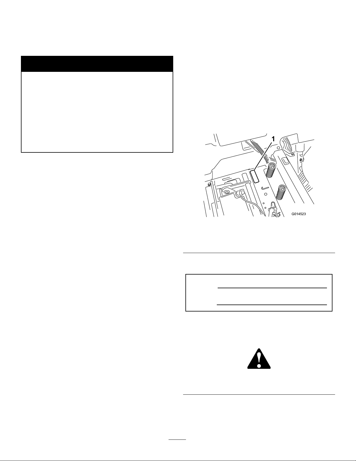
Wheneveryouneedservice,genuineT oroparts,oradditional
information,contactanAuthorizedServiceDealerorToro
CustomerServiceandhavethemodelandserialnumbersof
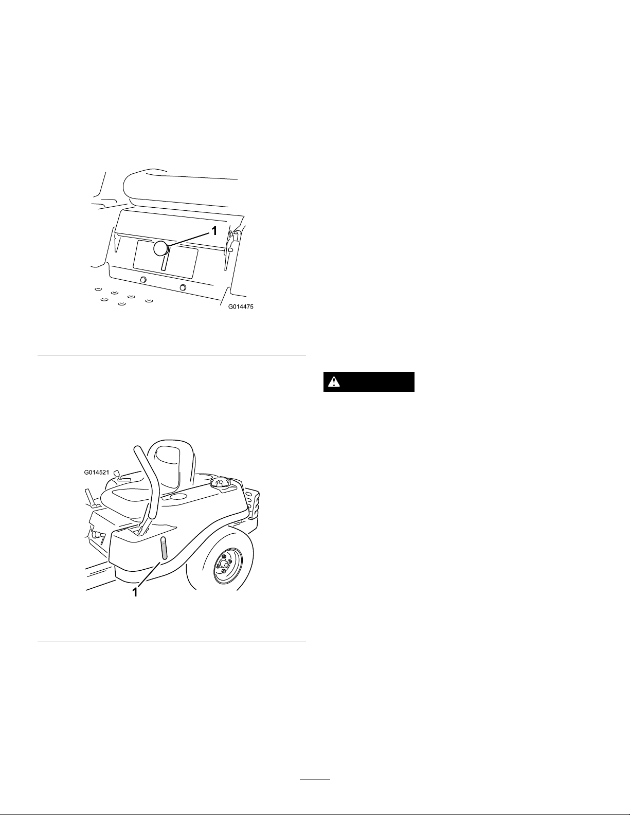
yourproductready.Figure1identiesthelocationofthe
modelandserialnumbersontheproduct.Writethenumbers
inthespaceprovided.
ThissparkignitionsystemcomplieswithCanadianICES-002.
Theenclosed
Engine Owner's Man ual
issuppliedfor
informationregardingtheUSEnvironmentalProtection
Agency(EPA)andtheCaliforniaEmissionControl
Regulationofemissionsystems,maintenance,and
warranty.Replacementsmaybeorderedthroughthe
enginemanufacturer.
Formodelswithstatedenginehorsepower,thegross
horsepoweroftheenginewaslaboratoryratedbytheengine
manufacturerinaccordancewithSAEJ1940.Ascongured
tomeetsafety,emission,andoperatingrequirements,the
actualenginehorsepoweronthisclassoflawnmowerwill
besignicantlylower.
Figure1
Undertheseat
1.Modelandserialnumberplate
Writetheproductmodelandserialnumbersinthespace
below:
ModelNo.
SerialNo.
Thismanualidentiespotentialhazardsandhassafety
messagesidentiedbythesafetyalertsymbol(Figure2),
whichsignalsahazardthatmaycauseseriousinjuryordeath
ifyoudonotfollowtherecommendedprecautions.
Figure2
1.Safetyalertsymbol.
©2014—TheToro®Company
8111LyndaleAvenueSouth
Bloomington,MN55420
Thismanualuses2wordstohighlightinformation.
Importantcallsattentiontospecialmechanicalinformation
andNoteemphasizesgeneralinformationworthyofspecial
attention.
Contactusatwww.Toro.com.
2
PrintedintheUSA.
AllRightsReserved
Page 3

Contents
Introduction..................................................................2
Safety...........................................................................4
SafeOperatingPractices...........................................4
SafetyandInstructionalDecals.................................6
ProductOverview.........................................................10
Controls...............................................................10
Operation....................................................................11
AddingFuel...........................................................11
CheckingtheEngine-oilLevel..................................13
BreakinginaNewMachine......................................13
ThinkSafetyFirst...................................................13
StartingtheEngine.................................................14
OperatingtheBlades...............................................15
TestingtheSafety-interlockSystem...........................16
StoppingtheEngine...............................................16
Driving.................................................................16
StoppingtheMachine.............................................18
AdjustingtheHeight-of-Cut....................................18
AdjustingtheAnti-scalpRollers(for42-inch
MowerDecks)....................................................18
PositioningtheSeat................................................19
AdjustingtheMotion-controlLevers.........................19
PushingtheMachinebyHand..................................19
OperatingTips......................................................21
Maintenance.................................................................22
RecommendedMaintenanceSchedule(s)......................22
PremaintenanceProcedures........................................23
RaisingtheSeat......................................................23
Lubrication...............................................................23
GreasingtheBearings.............................................23
EngineMaintenance..................................................24
ServicingtheAirCleaner.........................................24
ServicingtheEngineOil..........................................24
ServicingtheSparkPlug..........................................26
CleaningtheBlowerHousing...................................27
FuelSystemMaintenance...........................................27
ReplacingtheIn-lineFuelFilter................................27
ElectricalSystemMaintenance....................................28
ChargingtheBattery...............................................28
ServicingtheFuses.................................................30
DriveSystemMaintenance.........................................30
CheckingtheTirePressure......................................30
ReleasingtheElectricBrake.....................................31
MowerMaintenance...................................................31
ServicingtheCuttingBlades.....................................31
LevelingtheMowerDeck........................................34
RemovingtheMower..............................................36
InstallingtheMower...............................................37
ReplacingtheGrassDeector..................................37
MowerBeltMaintenance............................................38
InspectingtheBelts................................................38
ReplacingtheMowerBelt........................................38
Cleaning...................................................................40
WashingtheUndersideoftheMower........................40
Storage........................................................................41
CleaningandStorage..............................................41
Troubleshooting...........................................................42
Schematics...................................................................44
3
Page 4

Safety
Improperuseormaintenancebytheoperatororowner
canresultininjury.Toreducethepotentialforinjury,
complywiththesesafetyinstructions,andpayattentionto
thesafetyalertsymbol,whichmeansCaution,Warning,or
Danger—“personalsafetyinstruction.”Failuretocomply
withtheinstructionsmayresultinpersonalinjuryor
death.
Important:Thismachinewasmanufacturedaccording
totheappropriateregulatorystandardsineffectatthe
timeofmanufacture.Modifyingthismachineinany
waymaycauseittobeoutofcompliancewiththose
standardsandwiththeinstructionsinthis
Man ual
madebyeitherthemanufactureroranAuthorizedToro
Dealer.
Thisproductiscapableofamputatinghandsandfeet.Follow
allsafetyinstructionstoavoidseriousinjuryordeath.
Theowner/usercanpreventandisresponsibleforaccidents
orinjuriesoccurringtopeople,ordamagetoproperty.
Important:Theadditionofattachmentsmadeby
othermanufacturersthatdonotmeetAmerican
NationalStandardsInstitutecerticationwillcause
noncomplianceofthismachine.
.Modicationstothismachineshouldonlybe
Operator’ s
•Nevercarrypassengers.
•Donotmowinreverseunlessabsolutelynecessary.
Alwayslookdownandbehindbeforeandwhilebacking
up.
•Beawareofthemowerdischargedirectionanddonot
pointitatanyone.Avoiddischargingmaterialagainsta
wallorobstruction.Materialmayricochetbacktoward
theoperator.Stoptheblade(s)whencrossinggravel
surfaces.
•Donotoperatethemachinewithoutdeector,discharge
coverorentiregrasscollectionsysteminplaceand
working.
•Bealert,slowdownandusecautionwhenmakingturns.
Lookbehindandtothesidebeforechangingdirections.
•Neverleavearunningmachineunattended.Alwaysturn
offblades,setparkingbrake,stopengine,andremovekey
beforedismounting.
•Turnoffbladeswhennotmowing.Stoptheengine,wait
forallpartstocometoacompletestopandremovethe
keybeforecleaningthemachine,removingthegrass
catcheroruncloggingthedischargechute.
•Operatethemachineonlyindaylightorgoodarticial
light.
•Donotoperatethemachinewhileundertheinuence
ofalcoholordrugs.
SafeOperatingPractices
Thisproductiscapableofamputatinghandsandfeetand
throwingobjects.Alwaysfollowallsafetyinstructionsto
avoidseriousinjuryordeath.
ThefollowinginstructionsareadaptedfromANSIstandard
B71.1-2012.AllthelanguagewithinthisANSIstandard
appliestothismachine;however,duetotheapplicationof
thestandardacrossmanydifferenttypesofproductssome
statementscanseemgeneralormisleading.Intheseinstances,
Torohasrenedthestatementtoconveythemeaningofthe
standardwhilebettermatchingtheproductthisOperator's
Manualpertains.Safetyinformationinadditiontothe
instructionsfoundintheANSIstandardbelowcanbefound
inToroRidingMowerSafetyattheendofthissection.
GeneralOperation
•Read,understand,andfollowallinstructionsinthe
operator'smanualandonthemachinebeforestarting.
•Donotplacehandsorfeetnearrotatingpartsorunder
themachine.Keepclearofthedischargeopeningatall
times.
•Allowonlyresponsibleadultswhoarefamiliarwiththe
instructionstooperatethemachine.
•Cleartheareaofobjectssuchasrocks,toys,wire,etc.,
whichcouldbepickedupandthrownbytheblade.
•Besuretheareaisclearofotherpeoplebeforemowing.
Stopthemachineifanyoneentersthearea.
•Watchfortrafcwhenoperatingnearorcrossing
roadways.
•Useextracarewhenloadingorunloadingthemachine
intoatrailerortruck.
•Alwaysweareyeprotectionwhenoperatingthemower.
•Alwaysfollowtherecommendationsforanyapplication
ofcounterweights.
•Lightningcancausesevereinjuryordeath.Iflightning
isseenorthunderisheardinthearea,donotoperate
themachine;seekshelter.
SlopeOperation
Slopesareamajorfactorrelatedtolossofcontroland
tip-overaccidents,whichcanresultinsevereinjuryordeath.
Operationonallslopesrequiresextracaution.Ifyoucannot
backuptheslopeorifyoufeeluneasyonit,donotmowit.
•Donotmowslopesgreaterthan15degrees.
•Watchforditches,holes,rocks,dips,andrisesthatchange
theoperatingangle,asroughterraincouldoverturnthe
machine.
•Choosealowgroundspeedsoyouwillnothavetostop
whileoperatingonaslope.
•Donotmowslopeswhengrassiswet.Slippery
conditionsreducetractionandcouldcauseslidingand
lossofcontrol.
4
Page 5

•Alwayskeepthedrivewheelsengagedwhengoingdown
slopes.
•Reducespeedanduseextremecautiononslopes.
•Donotmakesuddenturnsorrapidspeedchanges.
•Removeormarkobstaclessuchasrocks,treelimbs,etc.
fromthemowingarea.Tallgrasscanhideobstacles.
•Avoidsuddenstartswhenmowinguphillbecausethe
mowermaytipbackwards.
•Beawarethatlossoftractionmayoccurgoingdownhill.
Weighttransfertothefrontwheelsmaycausedrive
wheelstoslipandcauselossofbrakingandsteering.
•Alwaysavoidsuddenstartingorstoppingonaslope.If
tireslosetraction,stopthemachine,disengagetheblades
andproceedslowlyofftheslope.
•Useextremecarewithgrasscatchersorotherattachments.
Thesecanchangethestabilityofthemachineandcause
lossofcontrol.
•Donottrytostabilizethemachinebyputtingyourfoot
ontheground.
•Donotmowneardrop-offs,ditches,steepbanksor
water.Wheelsdroppingoveredgescancauserollovers,
whichmayresultinseriousinjury,deathordrowning.
•Useawalkbehindmowerand/orahandtrimmernear
drop-offs,ditches,steepbanksorwater.
Children
Tragicaccidentscanoccuriftheoperatorisnotalerttothe
presenceofchildren.Childrenareoftenattractedtothe
machineandthemowingactivity.Neverassumethatchildren
willremainwhereyoulastsawthem.
•Keepchildrenoutofthemowingareaandunderthe
watchfulcareofanotherresponsibleadult,notthe
operator.
•Bealertandturnthemachineoffifchildrenenterthe
area.
•Beforeandwhilebackingorchangingdirection,look
behind,down,andside-to-sideforsmallchildren.
•Nevercarrychildren,evenwiththebladesoff.Theymay
falloffandbeseriouslyinjuredorinterferewithsafe
machineoperation.
•Childrenwhohavebeengivenridesinthepastmay
suddenlyappearinthemowingareaforanotherrideand
berunoverorbackedoverbythemower.
•Neverallowchildrentooperatethemachine.
•Useextracarewhenapproachingblindcorners,shrubs,
trees,theendofafenceorotherobjectsthatmayobscure
vision.
TowingSafety
•Donotattachtowedequipmentexceptatthehitchpoint.
•Followtheattachmentmanufacturer'srecommendation
forweightlimitsfortowedequipmentandtowingon
slopes.Towedweightmustnotexceedtheweightofthe
machine,operator,andballast.Usecounterweightsor
wheelweightsasdescribedintheattachment,orinthe
pullingmachineOperator’sManual.
•Neverallowchildrenorothersinorontowedequipment.
•Onslopes,theweightofthetowedequipmentmaycause
lossoftraction,increasedriskofrollover,andlossof
control.Reducethetowedweightandslowdown.
•Stoppingdistanceincreaseswiththeweightofthetowed
load.Travelslowlyandallowextradistancetostop.
•Makewideturnstokeeptheattachmentclearofthe
machine.
SafeHandlingofGasoline
Toavoidpersonalinjuryorpropertydamage,useextracare
whenhandlinggasolineandotherfuels.Theyareammable
andthevaporsareexplosive.
•Extinguishallcigarettes,cigars,pipesandothersources
ofignition.
•Useonlyanapprovedcontainer.
•Neverremovethegascaporaddfuelwhentheengineis
running.Allowtheenginetocoolbeforerefueling.
•Neverrefuelthemachineindoors.
•Neverstorethemachineorfuelcontainerinsidewhere
thereisanopename,suchasnearawaterheateror
furnace.
•Neverllcontainersinsideavehicleoronatruckor
trailerwithaplasticliner.Alwaysplacecontainersonthe
groundawayfromyourvehiclebeforelling.
•Removegas-poweredequipmentfromthetruckortrailer
andrefuelitontheground.Ifthisisnotpossible,then
refuelsuchequipmentwithaportablecontainer,rather
thanfromagasolinedispensernozzle.
•Keepthenozzleincontactwiththerimofthefueltank
orcontaineropeningatalltimesuntilthefuelingis
complete.Donotuseanozzlelock-opendevice.
•Iffuelisspilledonclothing,changeclothingimmediately.
•Neveroverllthefueltank.Replacegascapandtighten
securely.
GeneralService
•Neveroperateamachineinsideaclosedarea.Engine
exhaustcontainscarbonmonoxide,whichisanodorless,
deadlypoisonthatcankillyou.
•Keepnutsandboltstight,especiallythebladeattachment
bolts.Keepequipmentingoodcondition.
•Neverinterferewiththeintendedfunctionofasafety
deviceortoreducetheprotectionprovidedbyasafety
device.Checktheirproperoperationregularly.
•Keepthemachinefreeofgrass,leaves,orotherdebris
build-up.Cleanupoilorfuelspillagefuelsoakeddebris.
Allowthemachinetocoolbeforestoring.
•Stopandinspecttheequipmentifyoustrikeanobject.
Repair,ifnecessary,beforerestarting.
5
Page 6

•Nevermakeanyadjustmentsorrepairswiththeengine
running.
•Checkforproperbrakeoperationfrequently .Adjustand
serviceasrequired.
•Grasscatchercomponentsaresubjecttowear,damage
anddeterioration,whichcouldexposemovingpartsor
allowobjectstobethrown.Frequentlycheckcomponents
andreplacewithmanufacturers'recommendedparts,
whennecessary.
•Mowerbladesaresharpandcancut.Wraptheblade(s)or
weargloves,anduseextracautionwhenservicingthem.
SafetyandInstructionalDecals
Safetydecalsandinstructionsareeasilyvisibletotheoperatorandarelocatednearanyareaofpotential
danger.Replaceanydecalthatisdamagedorlost.
93-7009
1.Warning—don'toperatethemowerwiththedeectorupor
removed;keepthedeectorinplace.
2.Cutting/dismembermenthazardofhandorfoot,mower
blade—stayawayfrommovingparts.
•Maintainorreplacesafetyandinstructiondecalsas
necessary.
•UseonlygenuineTororeplacementpartstoensurethat
originalstandardsaremaintained.
106-8717
1.Readtheinstructionsbeforeservicingorperforming
maintenance.
2.Checktirepressureevery25operatinghours.
3.Greaseevery25operatinghours.
4.Engine
Manufacturer'sMark
1.Indicatesthebladeisidentiedasapartfromtheoriginal
machinemanufacturer.
105-7015
Formodelswith42-inchdecks
110-6691
1.Thrownobjecthazard—keepbystandersasafedistance
fromthemachine.
2.Thrownobjecthazard,mower—donotoperatewithoutthe
deector,dischargecover,orgrasscollectionsystemin
place.
3.Cutting/dismembermentofhandorfoot—stayawayfrom
movingparts.
114-1606
1.Entanglementhazard,belt—keepallguardsinplace.
6
Page 7
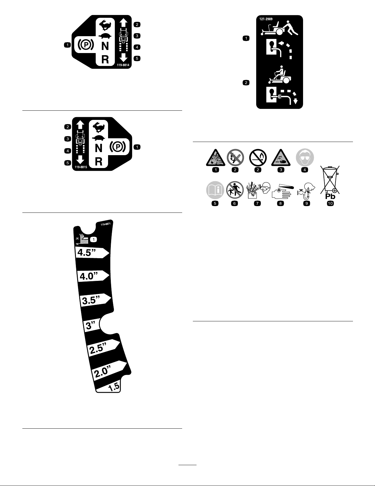
119-8814
1.Parkingposition4.Neutral
2.Fast5.Reverse
3.Slow
121-2989
119-8815
1.Parkingposition4.Neutral
2.Fast5.Reverse
3.Slow
1.Bypassleverpositionfor
pushingthemachine
2.Bypassleverpositionfor
BatterySymbols
Someorallofthesesymbolsareonyourbattery
1.Explosionhazard
2.Nore,opename,or
smoking.
3.Causticliquid/chemical
burnhazard
4.Weareyeprotection9.Flusheyesimmediately
5.ReadtheOperator's
Manual.
6.Keepbystandersasafe
7.Weareyeprotection;
8.Batteryacidcancause
10.Containslead;donot
operatingthemachine
distancefromthebattery.
explosivegasescan
causeblindnessandother
injuries
blindnessorsevereburns.
withwaterandgetmedical
helpfast.
discard.
119-8871
Certainmodelsonly
1.Height-of-cut
7
Page 8
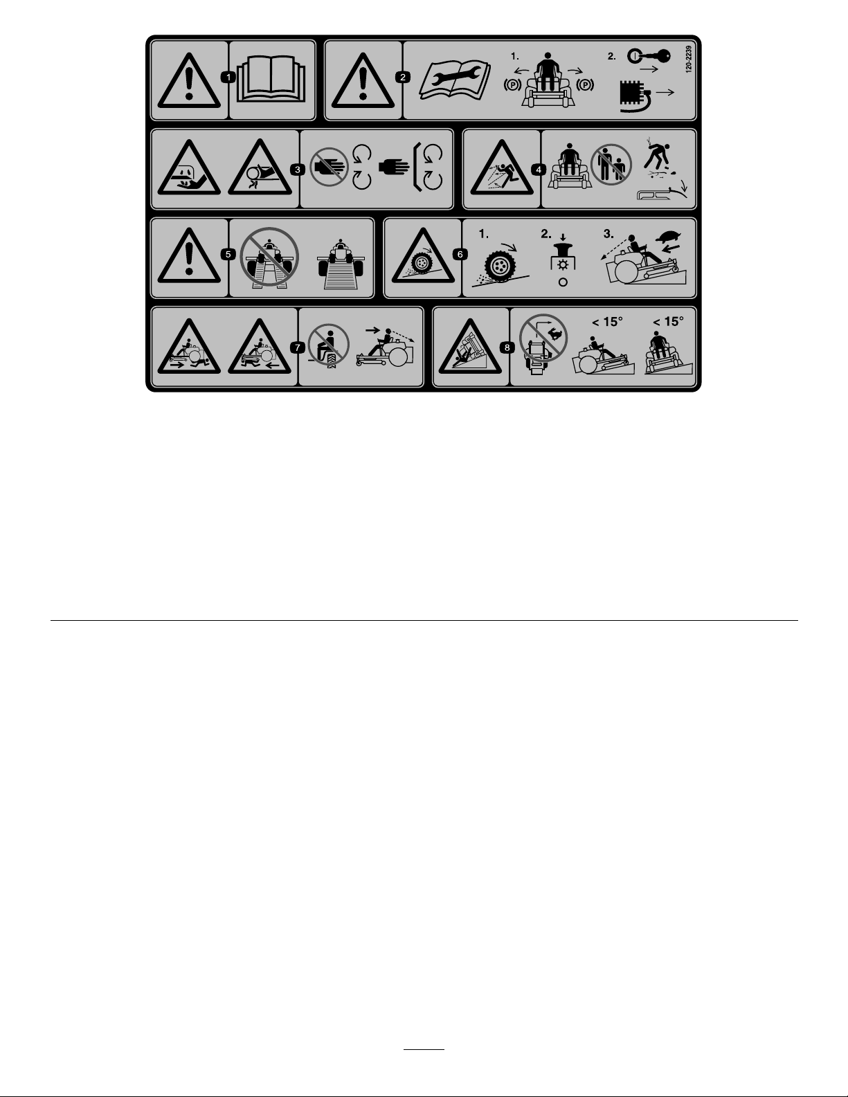
120-2239
1.Warning—readtheOperator'sManual.5.Warning—donotusesplitramps,useafullrampswhen
2.Warning—readtheinstructionsbeforeservicingorperforming
maintenance;movethemotioncontrolleverstothepark
(brake)position,removetheignitionkeyanddisconnectthe
sparkplugwire.
3.Cutting/dismembermenthazard,mowerblade;entanglement
hazard,belt—stayawayfrommovingparts,keepallguards
andshieldsinplace.
4.Thrownobjecthazard—keepbystandersasafedistancefrom
themachine,pickupdebrisbeforeoperating,keepdeector
inplace.
transportingmachine.
6.Lossoftraction/controlhazard,slopes—lossoftraction/control
onaslope,disengagethebladecontrolswitch(PTO),
proceedofftheslopeslowly.
7.Crushing/dismembermenthazardofbystanders,reversing;
crushing/dismembermenthazardofbystanders—donotcarry
passengers,lookbehindanddownwhenreversing.
8.Tippinghazard—donotmowslopesgreaterthan15degrees,
avoidsuddenandsharpturnswhileonslopes.
8
Page 9

121-0772
1.Fast
2.Continuous-variablesetting5.Powertake-off(PTO),blade-controlswitch
3.Slow
4.Choke
130-0780
1.Slow(trimandtow)2.Fast(mowandgo)
109-7076
9
Page 10
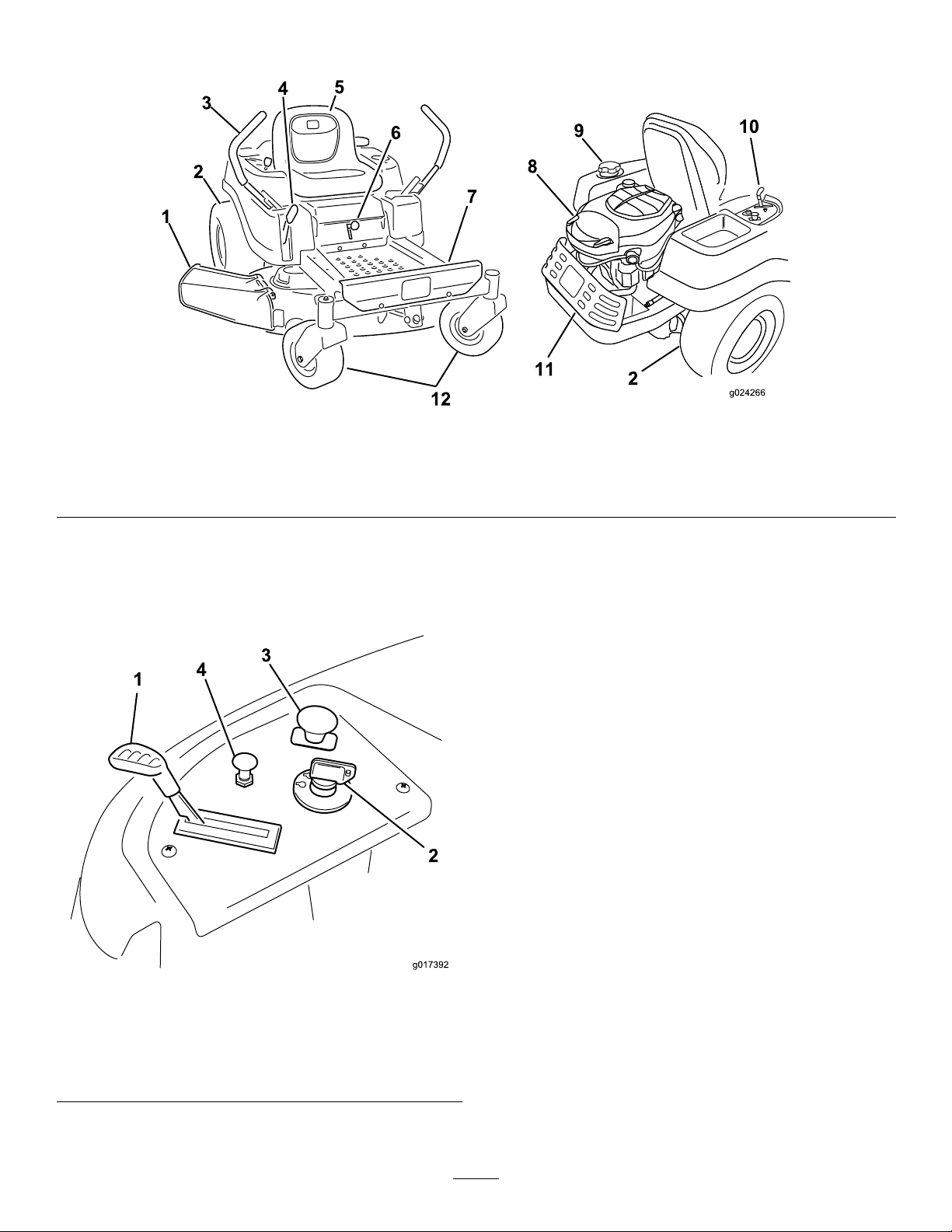
ProductOverview
Figure3
1.Deector4.Height-of-cutlever
2.Reardrivewheel
3.Motion-controllevers
5.Operatorseat
6.SmartSpeed™lever
Controls
BecomefamiliarwithallofthecontrolsinFigure3and
Figure4beforeyoustarttheengineandoperatethemachine.
7.Footrest
8.Engine11.Engineguard
9.Fuel-tankcap12.Frontcasterwheel
10.Controlpanel
IgnitionSwitch
Theignitionswitchhas3positions:Off,Run,andStart.The
keywillturntoStartandmovebacktoRunuponrelease.
TurningthekeytotheOffpositionwillstoptheengine;
however,alwaysremovethekeywhenleavingthemachine
topreventsomeonefromaccidentallystartingtheengine
(Figure4).
ThrottleControl
Thethrottlecontrolstheenginespeed,andithasa
continuous-variablesettingfromSlowtoFast(Figure4).
ChokeControl
PullupontheChokecontroluntilitstopstochokethe
engine(Figure4).PushdownontheChokecontrolfor
normalengineoperation
Figure4
ControlPanel
1.Throttle3.Blade-controlswitch
2.Ignitionswitch
(powertake-off)
4.Choke
Blade-controlSwitch(PowerTake-off)
Theblade-controlswitch,representedbyapowertake-off
(PTO)symbol,engagesanddisengagespowertothemower
blades(
Figure4).
Motion-controlLeversandPark
Position
Themotion-controlleversarespeed-sensitivecontrolsof
independent-wheelmotors.Movingaleverforwardor
backwardturnsthewheelonthesamesideforwardorin
10
Page 11
reverse;wheelspeedisproportionaltotheamountthelever
G014475
1
G014521
1
ismoved.Movethecontrolleversoutwardfromthecenter
totheparkposition,andexitthemachine(Figure16).Always
positionthemotion-controlleversintotheparkposition
whenyoustopthemachineorleaveitunattended.
Operation
Note:Determinetheleftandrightsidesofthemachine
fromthenormaloperatingposition.
SmartSpeed™ControlSystemLever
TheSmartSpeed™Control-Systemlever,locatedbelowthe
operatingposition,givestheoperatorachoicetodrivethe
machineat2speedranges—highandlow(Figure5).
Figure5
1.Smart-speedlever
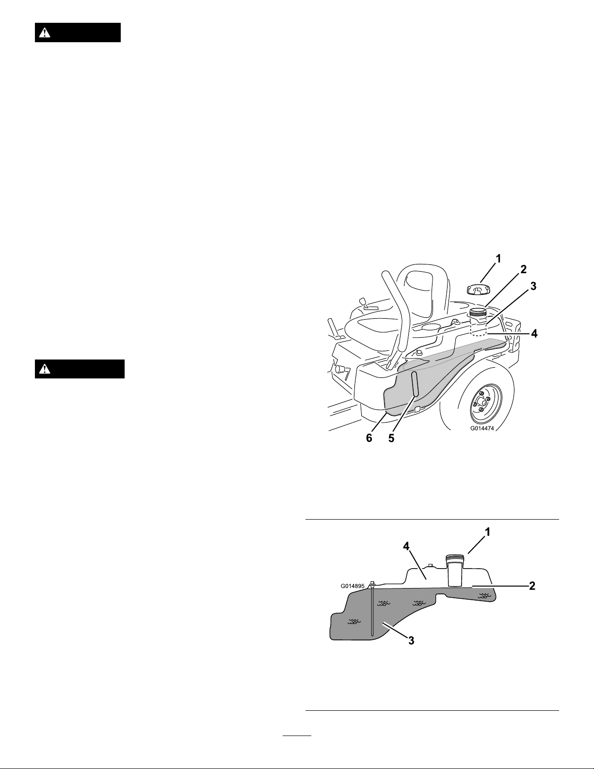
Fuel-presenceWindow
Thefuelwindowlocatedontheleft-handsideofthemachine
canbeusedtoverifythepresenceofgasolineinthetank
(Figure6).
AddingFuel
•Forbestresults,useonlyclean,fresh(lessthan30days
old),unleadedgasolinewithanoctaneratingof87or
higher((R+M)/2ratingmethod).
•Ethanol:Gasolinewithupto10%ethanol(gasohol)
or15%MTBE(methyltertiarybutylether)byvolume
isacceptable.EthanolandMTBEarenotthesame.
Gasolinewith15%ethanol(E15)byvolumeisnot
approvedforuse.Neverusegasolinethatcontains
morethan10%ethanolbyvolume,suchasE15
(contains15%ethanol),E20(contains20%ethanol),or
E85(containsupto85%ethanol).Usingunapproved
gasolinemaycauseperformanceproblemsand/orengine
damagewhichmaynotbecoveredunderwarranty.
•Donotusegasolinecontainingmethanol.
•Donotstorefueleitherinthefueltankorfuelcontainers
overthewinterunlessafuelstabilizerisused.
•Donotaddoiltogasoline.
DANGER
Incertainconditions,gasolineisextremely
ammableandhighlyexplosive.Areorexplosion
fromgasolinecanburnyouandothersandcan
damageproperty.
Figure6
1.Fuel-presencewindow
Height-of-CutLever
Theheight-of-cutleverallowstheoperatortolowerand
raisethedeckfromtheseatedposition.Whentheleveris
movedup(towardtheoperator),thedeckisraisedfromthe
ground,andwhenmoveddown(awayfromtheoperator),it
isloweredtowardtheground.Onlyadjusttheheight-of-cut
whilethemachineisnotmoving(Figure20).
•Fillthefueltankoutdoors,inanopenarea,
whentheengineiscold.Wipeupanygasoline
thatspills.
•Neverllthefueltankinsideanenclosedtrailer.
•Donotllthefueltankcompletelyfull.Add
gasolinetothefueltankuntilthelevelis6to13
mm(1/4to1/2inch)belowthebottomofthe
llerneck.Thisemptyspaceinthetankallows
gasolinetoexpand.
•Neversmokewhenhandlinggasoline,andstay
awayfromanopenameorwheregasoline
fumesmaybeignitedbyaspark.
•Storegasolineinanapprovedcontainerand
keepitoutofthereachofchildren.Neverbuy
morethana30-daysupplyofgasoline.
•Donotoperatewithoutentireexhaustsystemin
placeandinproperworkingcondition.
11
Page 12
DANGER
G014474
1
2
3
4
5
6
G014895
1
2
3
4
Incertainconditionsduringfueling,static
electricitycanbereleasedcausingasparkwhich
canignitethegasolinevapors.Areorexplosion
fromgasolinecanburnyouandothersandcan
damageproperty.
•Alwaysplacegasolinecontainersontheground
awayfromyourvehiclebeforelling.
•Donotllgasolinecontainersinsideavehicleor
onatruckortrailerbedbecauseinteriorcarpets
orplastictruckbedlinersmayinsulatethe
containerandslowthelossofanystaticcharge.
•Whenpractical,removegas-poweredequipment
fromthetruckortrailerandrefueltheequipment
withitswheelsontheground.
•Ifthisisnotpossible,thenrefuelsuch
equipmentonatruckortrailerfromaportable
container,ratherthanfromagasolinedispenser
nozzle.
•Ifagasolinedispensernozzlemustbeused,
keepthenozzleincontactwiththerimofthe
fueltankorcontaineropeningatalltimesuntil
fuelingiscomplete.
ofvarnishdepositsinthefuelsystem,usefuelstabilizer
atalltimes.
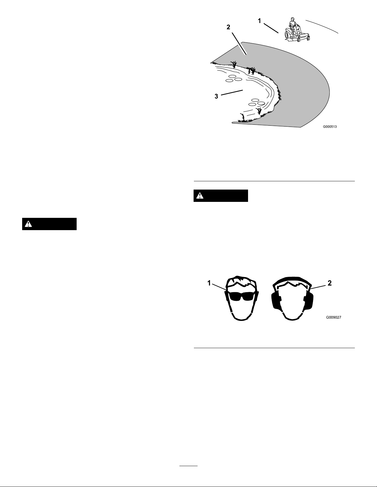
FillingtheFuelTank
Ensurethattheengineisshutoffandthemotioncontrolsare
intheparkedposition.
Important:Donotoverllfueltank.Fillthefueltank
tothebottomofthellerneck.Theemptyspaceinthe
tankallowsthefueltoexpand.Overllingmayresultin
fuelleakage,damagetotheengine,ordamagetothe
emissionssystem.
1.Cleanaroundthefuel-tankcapandremovethecap.
Note:Youcanusethefuelwindowtoverifythe
presenceofgasolinebeforellingthetank(Figure7).
2.Slowlyaddgasolineuntilthefuelreachesthebaseof
thellerneck(Figure7).
WARNING
Gasolineisharmfulorfatalifswallowed.Long-term
exposuretovaporscancauseseriousinjuryand
illness.
•Avoidprolongedbreathingofvapors.
•Keepfaceawayfromnozzleandgastankor
conditionerbottleopening.
•Avoidcontactwithskin;washoffspillagewith
soapandwater.
UsingStabilizer/Conditioner
Useafuelstabilizer/conditionerinthemachinetoprovide
thefollowingbenets:
•Keepsgasolinefreshduringstorageof90daysorless.
Forlongerstorageitisrecommendedthatthefueltank
bedrained.
•Cleanstheenginewhileitruns
•Eliminatesgum-likevarnishbuildupinthefuelsystem,
whichcauseshardstarting
Important:Donotusefueladditivescontaining
methanolorethanol.
Addthecorrectamountofgasstabilizer/conditionerto
thegas.
Note:Afuelstabilizer/conditionerismosteffective
whenmixedwithfreshgasoline.T ominimizethechance
Figure7
1.Fuel-tankcap
2.Fillopening5.Fuelwindow
3.Fillerneck
Figure8
1.Fillopening3.Fuel
2.Baseofthellerneck(do
notllpasthere)
4.Baseofthellerneck(do
notllpasthere)
6.Endofthefueltank
4.Emptyspace(forfuel
expansion)
12
Page 13
3.Installthefuel-tankcapsecurely ,andtightenuntilit
G009027
1
2
clicks.
CheckingtheEngine-oilLevel
Beforeyoustarttheengineandusethemachine,checktheoil
levelintheenginecrankcase;refertoCheckingtheEngine-oil
Level(page24).
BreakinginaNewMachine
Newenginestaketimetodevelopfullpower.Mowerdecks
anddrivesystemshavehigherfrictionwhennew,placing
additionalloadontheengine.Allow40to50hoursof
break-intimefornewmachinestodevelopfullpowerand
bestperformance.
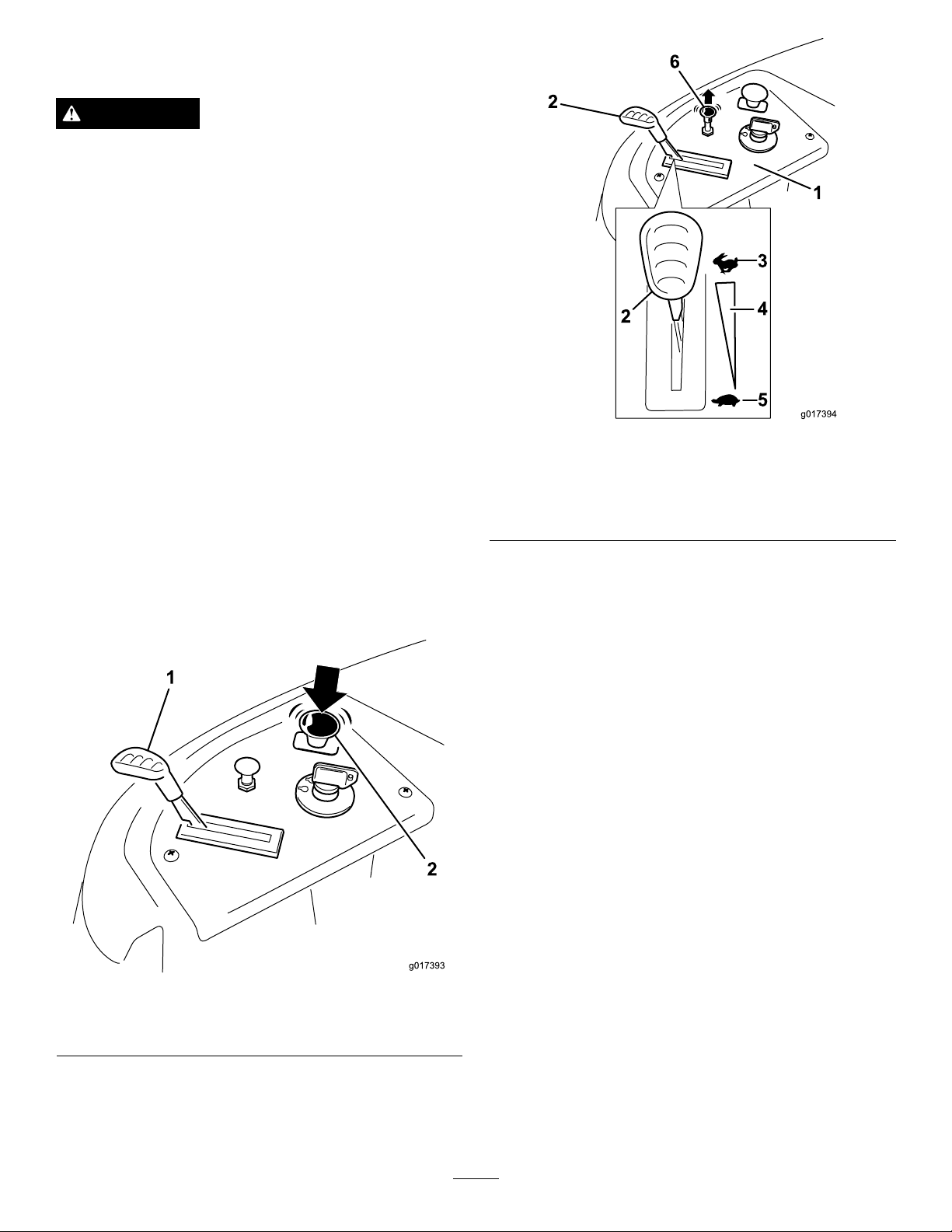
ThinkSafetyFirst
OperatingSafety
1.Safezone—usethe
TimeCutterhere
2.Useawalk-behindmower
and/orhandtrimmernear
drop-offsandwater.
Figure9
3.Water
Pleasecarefullyreadallofthesafetyinstructionsanddecals
inthesafetysection.Knowingthisinformationcouldhelp
you,yourfamily ,pets,orbystandersavoidinjury.
DANGER
Mowingonwetgrassorsteepslopescancause
slidingandlossofcontrol.
Wheelsdroppingoveredgescancauserollovers,
whichmayresultinseriousinjury,death,or
drowning.
Alossoftractionisalossofsteeringcontrol.
Toavoidlossofcontrolandpossibilityofrollover:
•Donotmowneardrop-offsornearwater.
•Donotmowslopesgreaterthan15degrees.
•Reducethespeedanduseextremecautionon
slopes.
•Whenmowingslopes,graduallyworkfrom
lowertohigherareasontheincline.
CAUTION
Thismachineproducessoundlevelsinexcessof85
dBAattheoperatorsearandcancausehearingloss
throughextendedperiodsofexposure.
Wearhearingprotectionwhenoperatingthis
machine.
Theuseofprotectiveequipmentforeyes,ears,feet,andhead
isrecommended.
Figure10
1.Wearsafetyglasses
2.Wearhearingprotection
•Avoidsuddenturnsorrapidspeedchanges.
•Turnup,intoaninclinewhenchanging
directionsonslopes.Turningdowntheslope
reducestraction.
•Attachmentschangethehandlingcharacteristics
ofthemachine.Useextracautionwhenusing
attachmentswiththemachine.
13
Page 14
UnderstandingtheSafety-interlock
System
WARNING
Ifsafety-interlockswitchesaredisconnectedor
damaged,themachinecouldoperateunexpectedly
causingpersonalinjury.
•Donottamperwiththeinterlockswitches.
•Checktheoperationoftheinterlockswitches
daily,andreplaceanydamagedswitchesbefore
operatingthemachine.
Thesafety-interlocksystemisdesignedtopreventtheengine
fromstartingunless:
•Thebladesaredisengaged.
•Themotion-controlleversareintheparkposition.
Thesafety-interlocksystemalsoisdesignedtostoptheengine
wheneverthecontrolleversareoutoftheparkpositionand
yourisefromtheseat.
StartingtheEngine
1.Sitdownontheseat,andmovethemotioncontrols
outwardtotheparkposition.
2.Disengagethebladesbymovingthebladecontrol
switchtoOff(Figure11)
Figure12
1.Controlpanel4.Continuous-variable
2.Throttle
3.Fast
4.TurntheignitionkeytoStarttoenergizethestarter
(Figure13).
Note:Whentheenginestarts,releasethekey.
Important:Donotengagethestarterformore
than10secondsatatime.Iftheenginefailsto
start,allowa60secondcooldownperiodbetween
attempts.Failuretofollowtheseinstructionscan
damagethestartermotor.
setting
5.Slow
6.Chokecontrol
Figure11
1.Controlpanel2.Blade-controlswitch—Off
position
3.PullupontheChokecontrolbeforestartingacold
engine(Figure12).
Note:Awarmorhotenginemaynotrequirechoking.
14
Page 15
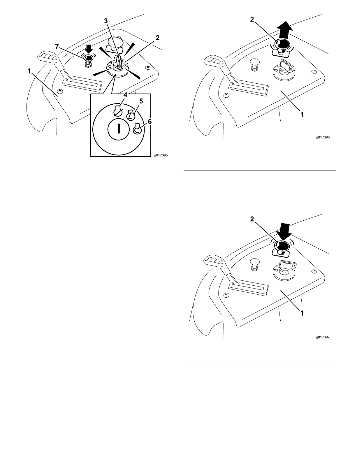
Figure14
Figure13
1.Controlpanel
2.Ignitionkey—runposition
3.Ignitionkey—startposition
4.Off
5.Run
6.Start
7.Chokecontrol
5.Aftertheenginestarts,pushdownontheChoke
control(
Figure13).
Note:Iftheenginestallsorhesitates,pullupon
theChokecontrol,andlettheenginerunforafew
seconds.Then,pushdownontheChokecontrol.
Repeatthisasrequired.
OperatingtheBlades
Theblade-controlswitch,representedbyapowertake-off
(PTO)symbol,engagesanddisengagespowertothemower
blades.Thisswitchcontrolspowertoanyattachmentsthat
drawpowerfromtheengine,includingthemowerdeckand
cuttingblades.
1.Controlpanel2.Blade-controlswitch—On
position
DisengagingtheBlades
Pushdownontheblade-controlswitchtomoveittotheOff
position,anddisengagetheblades(Figure15).
EngagingtheBlades
Important:Donotengagethebladeswhenparkedin
tallgrass.Beltorclutchdamagecanoccur.
1.Releasepressureonthemotion-controlleversand
placethemachineinneutral.
2.MovethethrottletotheFastposition.
Note:Alwaysengagethebladeswiththethrottlein
theFastposition.
3.Pullupontheblade-controlswitchtomoveittothe
Onposition,andengagetheblades(
Figure14).
Figure15
1.Controlpanel2.Blade-controlswitch—Off
15
Page 16

TestingtheSafety-interlock
Driving
System
Testthesafety-interlocksystembeforeyouusethemachine
eachtime.Ifthesafetysystemdoesnotoperateasdescribed
below,haveanAuthorizedServiceDealerrepairthesafety
systemimmediately.
1.Whilesittingontheseat,withthecontrolleversinpark
position,andmovetheblade-controlswitchtoOn.
2.Trystartingtheengine;theengineshouldnotcrank.
3.Whilesittingontheseat,movetheblade-control
switchtoOff.
4.Moveeithermotion-controllevertothecenter,
unlockedposition.
5.Trystartingtheengine;theengineshouldnotcrank.
6.Repeatwiththeothermotion-controllever.
7.Whilesittingontheseat,movetheblade-control
switchtoOff,andlockthemotion-controlleversin
theparkposition.
8.Starttheengine.
9.Whiletheengineisrunning,engagetheblade-control
switch,andriseslightlyfromtheseat.
Drivingthemachinebenetsfromanunderstandingof
whatzero-turn-radiusmowermeans.Thedrivewheelsturn
independently,poweredbyhydraulicmotorsoneachaxle;
henceonesidecanturninreversewhiletheotherturns
forwardcausingthemachinetospinratherthanturn.This
vastlyimprovesthemachinemaneuverabilitybutmayrequire
someadjustmentiftheoperatorisunfamiliar.
WARNING
Themachinecanspinveryrapidly.Theoperator
maylosecontrolofthemachineandcausepersonal
injuryordamagetothemachine.
•Usecautionwhenmakingturns.
•Slowthemachinedownbeforemakingsharp
turns.
Thethrottlecontrolregulatestheenginespeedasmeasured
inrpm(revolutionsperminute).Placingthethrottlecontrol
intheFastpositioncanbebestforperformance.Formost
applications,operatinginthefull-throttlepositionisdesirable.
Note:Theengineshouldstop.
10.Whilesittingontheseat,movetheblade-control
switchtoOff,andlockthemotion-controlleversin
theparkposition.
11.Starttheengine.
12.Whiletheengineisrunning,movethemotion-control
leverstothecenter,unlockedposition,engagethe
blade-controlswitch,andriseslightlyfromtheseat.
Note:Theengineshouldstop.
StoppingtheEngine
1.MovethethrottlelevertotheSlowposition.
2.Lowertheenginespeedtoidlespeed,andallowitto
runforatleastoneminute.
3.Disengagethebladesbymovingtheblade-control
switchtoOff(Figure15).
4.TurntheignitionkeytoOff(Figure13)andremove
thekey.
1.Park(brake)position
2.Center,unlockposition
Figure16
3.Forward
4.Backward
16
Page 17

UsingtheSmartSpeed™Control
G014475
1
G008952
System
DrivingForward
1.Movetheleverstothecenter,unlockedposition.
TheSmartSpeed™Control-Systemlever,locatedbelowthe
operatingposition(Figure17),givestheoperatorachoiceto
drivethemachineat2groundspeedranges—highandlow .
Figure17
1.Smart-speedlever
Tochangespeeds:
1.Movethemotioncontrolleverstoneutralandoutward
totheparkposition;disengagethebladecontrolswitch.
WARNING
Removingyourhandsfromthemotion-control
leverswhilethemachineisinmotioncan
resultinalossofcontrolcausingharmtoyou
orbystanders.
Alwaysstopthemachineandmovethe
motion-controlleverstotheparkposition
beforeadjustingtheSmartSpeed™Control
System.
2.Togoforward,slowlypushthemotion-controllevers
forward(Figure16).
Figure18
Togostraight,applyequalpressuretoboth
motion-controllevers(Figure16).
Toturn,releasepressureonthemotion-controllever
towardthedirectionyouwanttoturn(Figure16).
Thefartheryoumovethemotion-controlleversin
eitherdirection,thefasterthemachinewillmovein
thatdirection.
Tostop,pullthemotion-controlleverstotheNeutral
position.
2.Adjustthelevertothedesiredposition.
17
Page 18

DrivingBackward
G008953
G014476
1
2
3
1.Movetheleverstothecenter,unlockedposition.
2.Togobackward,lookbehindyouanddown,asyou
slowlypullthemotion-controlleversrearward(Figure
19).
Figure19
AdjustingtheHeight-of-Cut
Height-of-cutiscontrolledbytheleverlocatedtotherightof
theoperatingposition(Figure20).
1.Pullupandinwardonthelevertomoveittothe
desiredcuttingposition.
2.Onceatthedesiredcuttingposition,slowlylowerthe
leveruntilitengagestheposition.
Thetransportpositionisthehighestheight-of-cutpositionor
cuttingheight115mm(4.5inches)asshownin
Figure20.
Togostraight,applyequalpressuretoboth
motion-controllevers(Figure19).
Toturn,releasethepressureonthemotion-control
levertowardthedirectionyouwanttoturn.
Tostop,pushthemotion-controlleverstotheNeutral
position.
StoppingtheMachine
Tostopthemachine,movethemotion-controlleversto
neutralandoutwardtotheparkposition,disengagethe
blade-controlswitch,ensurethethrottleisintheFast
position,andturntheignitionkeytooff.
Note:Remembertoremovethekeyfromtheignitionswitch.
WARNING
Childrenorbystandersmaybeinjuredifthey
moveorattempttooperatethemowerwhileitis
unattended.
Alwaysremovetheignitionkeyandmovethe
motion-controlleversoutwardtotheparkposition
whenleavingthemachineunattended,evenifjust
forafewminutes.
Figure20
1.Height-of-cutlever3.115mm(4.5inches),
transportposition
2.Height-of-cutpositions
AdjustingtheAnti-scalp Rollers(for42-inchMower Decks)
Wheneveryouchangetheheight-of-cut,itisrecommended
toadjusttheheightoftheanti-scalprollers.
Note:Adjusttheanti-scalprollerssotherollersdonottouch
thegroundinnormal,atmowingareas.
1.Disengagetheblade-controlswitch(PTO),movethe
motion-controlleverstotheneutral-lockposition,and
settheparkingbrake.
2.Stoptheengine,removethekey,andwaitforallmoving
partstostopbeforeleavingtheoperatingposition.
3.Adjusttheanti-scalprollerstooneofthefollowing
positions:
18
Page 19

•Upperhole—usethispositionwiththemower
g019929
1
2
3
4
5
G014477
1
4
1
2
G014970
3
deckinthe63mm(2-1/2inches)andbelowthe
height-of-cutpositions(Figure21).
•Lowerhole—usethispositionwiththemower
deckinthe76mm(3inches)andabovethe
height-of-cutpositions(Figure21).
Figure21
AdjustingtheMotion-control Levers
AdjustingtheHeight
Themotion-controlleverscanbeadjustedhigherorlowerfor
maximumoperatorcomfort.
1.Removethe2boltsholdingthecontrollevertothe
control-armshaft(Figure23).
2.Movethecontrollevertothenextsetofholes.
3.Securetheleverwiththe2bolts(Figure23).
1.Anti-scalproller4.Upperhole—themower
2.Lowerhole—themower
deckinthe76mm(3
inches)andabovethe
height-of-cutpositions
3.Flangenut
deckinthe63mm(2-1/2
inches)andbelowthe
height-of-cutpositions
5.Bolt
PositioningtheSeat
Theseatcanmoveforwardandbackward.Positiontheseat
whereyouhavethebestcontrolofthemachineandaremost
comfortable.
1.Raisetheseat,andloosentheadjustmentboltsjust
enoughsothattheseatcanmove(
Figure22).
Figure23
1.Control-armshaft3.Slotted,upperhole
2.Controllever
4.Bolt
4.Repeattheadjustmentfortheoppositecontrollever.
AdjustingtheTilt
Themotion-controlleverscanbetiltedforeoraftfor
maximumoperatorcomfort.
1.Loosentheupperboltholdingthecontrollevertothe
control-armshaft.
2.Loosenthelowerboltjustenoughtopivotthecontrol
leverforeoraft(Figure23).
Note:Tightenbothboltstosecurethecontrolinthe
newposition.
1.Adjustmentbolts
Figure22
2.Movetheseattothedesiredpositionandtightenthe
bolts.
3.Repeattheadjustmentfortheoppositecontrollever.
PushingtheMachinebyHand
Important:Alwayspushthemachinebyhand.Donot
towthemachine,becausedamagemayoccur.
Thismachinehasanelectric-brakemechanism,andtopush
themachine,theignitionkeyneedstobeintheRunposition.
Thebatteryneedstobechargedandfunctioningforthe
electricbraketobedisengage.
19
Page 20

PushingtheMachine
g017303
1 2
3
1.Parkthemachineonalevelsurface,anddisengagethe
blade-controlswitch.
2.Movethemotion-controlleversoutwardtothepark
position,stoptheengine,andwaitforallmovingparts
tostopbeforeleavingtheoperatingposition.
3.Locatethebypassleversontheframeonbothsidesof
theengine.
4.Movethebypassleversforwardthroughthekeyhole
anddowntolocktheminplace(
Note:Ensurethisisdoneforeachlever.
5.Movethemotion-controlleversinwardtotheneutral
positionandturntheignitionkeytotheRunposition.
Note:Donotstartthemachine.
Note:Youcannowpushthemachinebyhand.
Figure24).
Figure24
1.Bypass-leverlocations
2.Leverpositionfor
operatingthemachine
3.Leverpositionforpushing
themachine
6.Whennished,ensurethatthekeyreturnstotheStop
positiontoavoiddrainingthebatterycharge.
Note:Ifthemachinefailstomove,theelectricbrakemay
stillbeengaged.Ifnecessary,theelectricbrakecanrelease
manually;refertoReleasingtheElectricBrake(page31).
OperatingtheMachine
Movethebypassleversrearwardthroughthekeyholeand
downtolocktheminplaceasshowninFigure24.
Note:Ensurethisisdoneforeachlever.
20
Page 21

OperatingTips
UsingtheFastThrottleSetting
Forbestmowingandmaximumaircirculation,operate
theengineattheFastthrottleposition.Airisrequiredto
thoroughlycutgrassclippings,sodonotsettheheight-of-cut
solowastototallysurroundthemowerbyuncutgrass.
Alwaystrytohaveonesideofthemowerfreefromuncut
grass,whichallowsairtobedrawnintothemower.
UsingtheSmartSpeed™Control
System
TheSmartSpeed™Control-Systemlever,locatedbelow
theoperatingposition,givestheoperatorachoicetodrive
themachineat2speedranges—highandlow.Anoperator
canbenetfromthelowerspeedsettingwhenmaneuvering
themachineintightspacesoroperatingarounddelicate
landscapes.Thelowsettingcanalsooperatethemachineata
highthrottlesettingandbladespeed,whilestillbeingableto
reducethegroundspeedtoincreasethequalityofcut.
CuttingLongGrass
Ifthegrassisallowedtogrowslightlylongerthannormal,
orifitcontainsahighdegreeofmoisture,raisethecutting
heighthigherthanusualandcutthegrassatthissetting.Then
cutthegrassagainusingthelower,normalsetting.
StoppingtheMachine
Ifyoumuststoptheforwardmotionofthemachinewhile
mowing,aclumpofgrassclippingsmaydropontoyour
lawn.Toavoidthis,moveontoapreviouslycutareawiththe
bladesengagedoryoucandisengagethemowerdeckwhile
movingforward.
KeepingtheUndersideoftheMower
Clean
Cleanclippingsanddirtfromtheundersideofthemower
aftereachuse.Ifgrassanddirtbuildupinsidethemower,
cuttingqualitywilleventuallybecomeunsatisfactory.
CuttingaLawnfortheFirstTime
Cutgrassslightlylongerthannormaltoensurethatthe
cuttingheightofthemowerdoesnotscalpanyuneven
ground.However,thecuttingheightusedinthepastis
generallythebestonetouse.Whencuttinggrasslongerthan
sixinchestall,youmaywanttocutthelawntwicetoensure
anacceptablequalityofcut.
Cutting1/3oftheGrassBlade
Itisbesttocutonlyabout1/3ofthegrassblade.Cutting
morethanthatisnotrecommendedunlessgrassissparse,or
itislatefallwhengrassgrowsmoreslowly.
AlternatingtheMowingDirection
Alternatethemowingdirectiontokeepthegrassstanding
straight.Thisalsohelpsdisperseclippingswhichenhances
decompositionandfertilization.
MowingatCorrectIntervals
Normally,mowevery4days.But,remember,grassgrowsat
differentratesatdifferenttimes.Sotomaintainthesame
cuttingheight,whichisagoodpractice,andmowmoreoften
inearlyspring.Asthegrassgrowthrateslowsinmidsummer,
mowlessfrequently.Ifyoucannotmowforanextended
period,rstmowatahighcuttingheight,thenmowagain2
dayslateratalowerheightsetting.
MaintainingtheBlade(s)
Maintainasharpbladethroughoutthecuttingseasonbecause
asharpbladecutscleanlywithouttearingorshreddingthe
grassblades.Tearingandshreddingturnsgrassbrownat
theedges,whichslowsgrowthandincreasesthechanceof
disease.Checkthemowerbladesaftereachuseforsharpness,
andforanywearordamage.Filedownanynicksandsharpen
thebladesasnecessary.Ifabladeisdamagedorworn,replace
itimmediatelywithagenuineTororeplacementblade.
AvoidingCuttingTooLow
Ifthecuttingwidthofthemoweriswiderthanthemower
youpreviouslyused,raisethecuttingheighttoensurethat
uneventurfisnotcuttooshort.
21
Page 22

Maintenance
Note:Determinetheleftandrightsidesofthemachinefromthenormaloperatingposition.
RecommendedMaintenanceSchedule(s)
MaintenanceService
Interval
Beforeeachuseordaily
Aftereachuse
Every25hours
Every50hours
Every100hours
Every200hours
Every500hours
Beforestorage
MaintenanceProcedure
•Checkthesafety-interlocksystem.
•Checktheaircleanerfordirty,looseordamagedparts.
•Checktheengine-oillevel.
•Checkthecuttingblades.
•Inspectthegrassdeectorfordamage.
•Cleanthemower-deckhousing.
•Greaseallthelubricationpoints.
•Checktirepressure.
•Checkthebeltsforwearorcracks.
•Servicethepaperelement(moreoftenunderextremelydusty,dirtyconditions).
•Replacethepaperelement(moreoftenunderextremelydusty,dirtyconditions).
•Changetheengineoilandtheengine-oillter.
•Cleantheblowerhousing(moreoftenunderextremelydusty,dirtyconditions).
•Replacethein-linefuellter.
•Checksparkplug(s)conditionandgap.
•Replacethesparkplug(s).
•Chargethebatteryanddisconnectbatterycables.
•Performallmaintenanceprocedureslistedabovebeforestorage.
•Paintanychippedsurfaces.
Important:Refertoyourengine
Owner's Man ual
foradditionalmaintenanceprocedures.
CAUTION
Ifyouleavethekeyintheignitionswitch,someonecouldaccidentlystarttheengineandseriouslyinjure
youorotherbystanders.
Removethekeyfromtheignitionanddisconnectthewirefromthesparkplugbeforeyoudoany
maintenance.Setthewireasidesothatitdoesnotaccidentallycontactthesparkplug.
22
Page 23

Premaintenance
1
G014522
Lubrication
Procedures
RaisingtheSeat
Makesurethatthemotion-controlleversarelockedinthe
parkposition.Lifttheseatforward.
Thefollowingcomponentscanbeaccessedbyraisingtheseat:
•Serialplate
•Servicedecal
•Seatadjustmentbolts
•Fuellter
•Batteryandbatterycables
GreasingtheBearings
ServiceInterval:Every25hours—Greaseallthelubrication
points.
GreaseType:No.2generalpurpose,lithium-basegrease
1.Parkthemachineonalevelsurface,anddisengagethe
blade-controlswitch.
2.Movethemotion-controlleversoutwardtothepark
position,stoptheengine,removethekey ,andwaitfor
allmovingpartstostopbeforeleavingtheoperating
position.
3.Cleanthegreasettings(Figure25andFigure26)with
arag.
Note:Makesuretoscrapeanypaintoffthefrontof
thetting(s).
Figure25
1.Frontcastertire
Figure26
Locatedontheseat-panunderside
1.Readtheinstructions
beforeservicingor
performingmaintenance
2.Checkthetirepressure
every25operatinghours
3.Greaseevery25operating
hours
4.Engine
4.Connectagreaseguntoeachtting(Figure25and
Figure26).
5.Pumpgreaseintothettingsuntilgreasebeginsto
oozeoutthebearings.
23
Page 24

EngineMaintenance
g023919
1 2
3
4
g017552
0
0
50
SAE 30
ServicingtheAirCleaner
ServiceInterval:Beforeeachuseordaily—Checktheair
cleanerfordirty,looseordamagedparts.
Every50hours—Servicethepaperelement(more
oftenunderextremelydusty,dirtyconditions).
Every100hours—Replacethepaperelement(more
oftenunderextremelydusty,dirtyconditions).
Thisengineisequippedwithareplaceable,highdensitypaper
air-cleanerelement.Checktheaircleanerdailyorbefore
startingtheengine.Checkforabuildupofdirtanddebris
aroundtheair-cleanersystem.Keepthisareaclean.Also,
checkforlooseordamagedcomponents.Replaceallbentor
damagedair-cleanercomponents.
Note:Operatingtheenginewithlooseordamaged
air-cleanercomponentscouldallowunlteredairintothe
engine,causingprematurewearandfailure.
Note:Servicetheaircleanermoreoftenunderextremely
dusty,dirtyconditions.
1.Rotatethelatchesoutward.
2.Removethecovertoaccesstheair-cleanerelement
(Figure27).
3.Removetheelement,andgentlytaptheelementto
dislodgedirt.
Note:Donotwashthepaperelementoruse
pressurizedair,asthiswilldamagetheelement.
Note:Replaceadirty,bent,ordamagedelement.
Handlethenewelementcarefully;donotuseifthe
sealingsurfacesarebentordamaged.
Figure27
1.Air-cleanerlatch3.Paperelement
2.Engine4.Air-cleanerbase
ServicingtheEngineOil
OilType:Detergentoil(APIserviceSJorhigher)
CrankcaseCapacity:1.9L(64oz)whenthelterischanged
Viscosity:Seethetablebelow.
4.Cleantheair-cleanerbaseasrequired,andcheckthe
condition.
5.Installthepaperelementontotheair-cleanerbase.
6.Installthecover,andsecureitwiththelatches(Figure
27).
Figure28
CheckingtheEngine-oilLevel
ServiceInterval:Beforeeachuseordaily—Checkthe
engine-oillevel.
1.Parkthemachineonalevelsurface,disengagethe
blade-controlswitch,stoptheengine,andremovethe
key.
2.Makesurethattheengineisstopped,level,andiscool,
sotheoilhashastimetodrainintothesump.
3.Tokeepdirt,grassclippings,etc.,outoftheengine,
cleantheareaaroundtheoil-llcap/dipstickbefore
removingit.
4.Removethedipstickandwipetheoilofffromit
(
Figure29).
24
Page 25

5.Insertthedipstickintothetube.
g023855
1
2
3
4
Figure29
1.Oildipstick3.Oillevel—Lowmark
2.Oillevel—Fullmark
4.Fillertube
6.Pullthedipstickout,andchecktheoillevel(Figure29).
ChangingtheEngineOilandthe
Engine-oilFilter
ServiceInterval:Every100hours—Changetheengineoil
andtheengine-oillter.
Fillwithoilasspeciedinthe“ViscosityGrades”table
(Figure28).
Changetheengineoilandtheengine-oillterwhilethe
engineisstillwarm.Theoilwillowmorefreelyandcarry
awaymoreimpurities.Makesurethattheengineislevelwhen
lling,checking,orchangingtheoil.
Changetheengineoilandtheengine-oillterasfollows:
1.Parkthemachine,sothatthedrainsideisslightlylower
thantheoppositeside,toensurethattheoildrains
completely.
2.Disengagetheblade-controlswitchandmovethe
motioncontrolsoutwardtotheparkposition.
3.Stoptheengine,removethekey,andwaitforallmoving
partstostopbeforeleavingtheoperatingposition.
4.Locatetheoil-drainhoseontheleftsideoftheengine.
(Figure30).
Note:Theoillevelshouldbeupto,butnotover,the
FullorFmarkonthedipstick
7.Ifthelevelislow ,addoilofthepropertype,uptothe
FullorFmarkonthedipstick.
Note:Alwayscheckthelevelwiththedipstickbefore
addingmoreoil.
Note:Topreventextensiveenginewearordamage,
alwaysmaintaintheproperoillevelinthecrankcase.
Neveroperatetheenginewiththeoillevelbelowthe
AddorLmarkorabovetheFullorFmarkonthe
dipstick.
8.Removedipstickandcheckoillevel.
Note:ThelevelshouldbebetweentheFullorFand
AddorLmarks.Iflow ,addoilofthepropertypeup
tothefullmark.
9.Installtheoil-llcap/dipstick.
Note:Thedrainplugisattachedtothedrainhose.
5.Cleantheareaaroundtheoil-drainplugandthe
oil-drainhose.
6.Placeadrainpanunderneaththemachine,directly
belowtheoil-drainhoseasshownin
Figure30
1.Oil-drainplug3.Oil-drainhose
2.Pan
Figure30.
7.Using2wrenches(onetoholdtheoil-drainhoseand
onetoloosentheplug),removetheoil-drainplug
(
Figure30).
8.Removetheoil-llcap/dipstick(Figure29).
9.Allowampletimeforcompletedrainage.
25
Page 26

10.Locatetheoillterontherightsideoftheengine,and
G023857
1
2
removetheoldlterandwipeoffthelteradapter
withacleancloth(Figure31).
ServicingtheSparkPlug
ServiceInterval:Every200hours—Checksparkplug(s)
conditionandgap.
Every500hours—Replacethesparkplug(s).
ThesparkplugisRFIcompliant.Equivalentalternatebrand
plugscanalsobeused.
Type:ChampionXC12YC(orequivalent)
AirGap:0.76mm(0.03inch)
RemovingtheSparkPlug
1.Disengagetheblade-controlswitch,movethemotion
controlsoutwardtotheparkposition,stoptheengine,
andremovethekey.
2.Beforeremovingthesparkplug(s),cleanthearea
aroundthebaseoftheplugtokeepdirtanddebrisout
oftheengine.
Figure31
1.Oillter
2.Adapter
11.Applyathinlmofcleanoiltotherubbergasketon
thenewlter.
12.Installthereplacementoilltertotheadapter.
13.Turntheoillterclockwiseuntiltherubbergasket
contactsthepad,thentightenthelteranadditional
3/4to1turn(
Figure31).
14.Wipeupanyexcessoilontheframe.
15.Whenoilhasdrainedcompletely ,installtheoildrain
plug.
16.Torquetheplugto14N-m(125in-lb).
17.Wipeupanyexcessoil(Figure30).
Note:Disposeoftheusedoilatarecyclingcenter.
18.Slowlypourapproximately80%ofthespeciedoil
intothellertube(Figure29).
19.Installtheoil-llcap/dipstick(
Figure29).
3.Pullthewireoffthesparkplug(s)(
Figure32).
4.Removethesparkplug(s)andthemetalwasher.
Figure32
1.Sparkplugandwirelocations
20.Checktheoillevel(
Figure29).
21.SlowlyaddadditionaloiltobringittotheFullmark.
22.Installtheoil-llcap/dipstick(Figure29).
26
Page 27

CheckingtheSparkPlug
G008794
1
2
g023859
1
2
3
4
5
Important:Donotcleanthesparkplug(s).Always
replacethesparkplug(s)whenithas:ablackcoating,
wornelectrodes,anoilylm,orcracks.
Ifyouseelightbrownorgrayontheinsulator,theengineis
operatingproperly .Ablackcoatingontheinsulatorusually
meanstheaircleanerisdirty.
Setthegapto0.76mm(0.030inch).
FuelSystem
Maintenance
DANGER
Incertainconditions,gasolineisextremely
ammableandhighlyexplosive.Areorexplosion
fromgasolinecanburnyouandothersandcan
damageproperty.
•Performanyfuelrelatedmaintenancewhenthe
engineiscold.Dothisoutdoorsinanopenarea.
Wipeupanygasolinethatspills.
•Neversmokewhendraininggasoline,andstay
awayfromanopenameorwhereasparkmay
ignitethegasolinefumes.
Figure33
InstallingtheSparkPlug
1.Installthesparkplug.
Note:Makesurethattheairgapissetcorrectly.
2.Tightenthesparkplugto25to29N-m(18to22ft-lb).
3.Pushthewireontothesparkplug(
Figure32).
CleaningtheBlowerHousing
Toensurepropercooling,makesurethegrassscreen,cooling
ns,andotherexternalsurfacesoftheenginearekeptclean
atalltimes.
Annually,orevery100hoursofoperation(moreoften
underextremelydusty,dirtyconditions),removetheblower
housing,andanyothercoolingshrouds.Cleanthecooling
nsandexternalsurfacesasnecessary.Makesurethatthe
coolingshroudsareinstalled.Torquetheblowerhousing
screwsto7.5N-m(5.5ft-lb).
ReplacingtheIn-lineFuel Filter
ServiceInterval:Every100hours—Replacethein-linefuel
lter.
Neverinstalladirtylterifitisremovedfromthefuelline.
1.Parkthemachineonalevelsurfaceanddisengagethe
blade-controlswitch.
2.Movethemotion-controlleversoutwardtothepark
position,stoptheengine,removethekey ,andwaitfor
allmovingpartstostopbeforeleavingtheoperating
position.
3.Locatethefuellteronthesideoftheengine(Figure
34).
Important:Operatingtheenginewithablockedgrass
screen,dirtyorpluggedcoolingns,and/orcooling
shroudsremoved,willcauseenginedamagedueto
overheating.
1.Fuellinefromtank
2.In-linefuellter
3.Flow-directionarrow
27
Figure34
4.Fuellinetoengine
5.Hoseclamp
Page 28

4.Squeezetheendsofthehoseclampstogetherandslide
themawayfromthelter(Figure34).
ElectricalSystem
5.Removethelterfromthefuellines.
6.Installanewlterwiththeow-directionarrow
comingfromthefueltankandpointingtotheengine.
7.Movethehoseclampsclosetothelter(
tosecureitinplace.
Figure34)
Maintenance
WARNING
CALIFORNIA
Proposition65Warning
Batteryposts,terminals,andrelated
accessoriescontainleadandleadcompounds,
chemicalsknowntotheStateofCalifornia
tocausecancerandreproductiveharm.
Washhandsafterhandling.
ChargingtheBattery
RemovingtheBattery
WARNING
Batteryterminalsormetaltoolscouldshortagainst
metalmachinecomponentscausingsparks.Sparks
cancausethebatterygassestoexplode,resulting
inpersonalinjury.
•Whenremovingorinstallingthebattery,donot
allowthebatteryterminalstotouchanymetal
partsofthemachine.
•Donotallowmetaltoolstoshortbetween
thebatteryterminalsandmetalpartsofthe
machine.
1.Parkthemachineonalevelsurfaceanddisengagethe
blade-controlswitch.
2.Movethemotion-controlleversoutwardtothepark
position,stoptheengine,removethekey ,andwaitfor
allmovingpartstostopbeforeleavingtheoperating
position.
3.Raisetheseattoaccessthebattery.
4.Disconnectthenegative(black)groundcablefromthe
batterypost(
Note:Retainallfasteners.
Figure35).
28
Page 29

WARNING
G005072
1
2
3
4
5
6
7
Incorrectbattery-cableroutingcoulddamage
themachineandcablescausingsparks.
Sparkscancausethebatterygassesto
explode,resultinginpersonalinjury.
ChargingtheBattery
ServiceInterval:Beforestorage—Chargethebatteryand
disconnectbatterycables.
1.Removethebatteryfromthechassis;referto
theBattery(page28)
.
Removing
•Alwaysdisconnectthenegative(black)
batterycablebeforedisconnectingthe
positive(red)cable.
•Alwaysconnectthepositive(red)battery
cablebeforeconnectingthenegative
(black)cable.
5.Slidetherubbercoverupthepositive(red)cable.
6.Disconnectthepositive(red)cablefromthebattery
post(Figure35).
Note:Retainallfasteners.
7.Removethebatteryhold-down(
batteryfromthebatterytray .
Figure35),andliftthe
2.Chargethebatteryforaminimumof1hourat6to
10amps.
Note:Donotoverchargethebattery.
3.Whenthebatteryisfullycharged,unplugthecharger
fromtheelectricaloutlet,thendisconnectthecharger
leadsfromthebatteryposts(
Figure36
1.Positive(+)batterypost3.Red(+)chargerlead
2.Negative(–)batterypost4.Black(–)chargerlead
Figure36).
1.Battery
2.Positive(+)batterypost
3.Bolt,washer,andnut7.Batteryhold-down
4.Terminalboot
Note:Donotrunthemachinewiththebattery
disconnected,electricaldamagemayoccur.
InstallingtheBattery
1.Positionthebatteryinthetray(Figure35).
2.Usingthefastenerspreviouslyremoved,installthe
positive(red)batterycabletothepositive(+)battery
terminal.
Figure35
5.Negative(–)batterypost
6.Wingnut,washer,andbolt
3.Usingthefastenerspreviouslyremoved,installthe
negativebatterycabletothenegative(-)battery
terminal.
4.Slidetheredterminalbootontothepositive(red)
batterypost.
5.Securethebatterywiththehold-down(Figure35).
6.Lowertheseat.
29
Page 30

ServicingtheFuses
30
25
30
25
G014921
2
1
DriveSystem
Theelectricalsystemisprotectedbyfuses.Itrequires
nomaintenance;however,ifafuseblows,checkthe
component/circuitforamalfunctionorshort.
Fusetype:
•Main—F1-30amp,blade-type
•ChargeCircuit—F2-25amp,blade-type
1.Removethescrewssecuringthecontrolpaneltothe
machine.
Note:Retainallfasteners.
2.Liftthecontrolpaneuptoaccessthemainwiring
harnessandfuseblock(
3.Toreplaceafuse,pulloutonthefusetoremoveit
(Figure37).
Figure37).
Maintenance
CheckingtheTirePressure
ServiceInterval:Every25hours—Checktirepressure.
Maintaintheairpressureinthefrontandreartiresas
specied.Uneventirepressurecancauseunevencut.Check
thepressureatthevalvestem(Figure38).Checkthetires
whentheyarecoldtogetthemostaccuratepressurereading.
Refertothemaximumpressuresuggestedbythetire
manufactureronthesidewallofthecasterwheeltires.
Inatethereardrive-wheeltiresto82kPa(12psi).
Figure38
Figure37
1.Main—30amp
2.Chargecircuit—25amp
4.Returnthecontrolpaneltoitsoriginalposition.
Note:Usethescrewsremovedpreviouslytosecure
thepaneltothemachine.
1.Valvestem
30
Page 31

ReleasingtheElectricBrake
G015000
1
Theelectricbrakereleasesbymanuallyrotatingthelinkarms
forward.Oncetheelectricbrakeisenergized,thebrakewill
reset.
1.Locatetheshaftontheelectricbrakewherethe
brake-linkarmsareconnected(Figure39).
2.Rotatetheshaftforwardtoreleasethebrake.
Figure39
1.Brake-linkarmontheelectric-brake-controlmodule
MowerMaintenance
ServicingtheCuttingBlades
Maintainsharpbladesthroughoutthecuttingseason,because
sharpbladescutcleanlywithouttearingorshreddingthegrass
blades.Tearingandshreddingturnsgrassbrownattheedges,
whichslowsgrowth,andincreasesthechanceofdisease.
Checkthecutterbladesdailyforsharpness,andforany
wearordamage.Filedownanynicksandsharpenthe
bladesasnecessary.Ifabladeisdamagedorworn,replace
itimmediatelywithagenuineT ororeplacementblade.For
convenientsharpeningandreplacement,youmaywantto
keepextrabladesonhand.
WARNING
Awornordamagedbladecanbreak,andapiece
ofthebladecouldbethrownintotheoperator's
orbystander'sarea,resultinginseriouspersonal
injuryordeath.
•Inspectthebladeperiodicallyforwearor
damage.
•Replaceawornordamagedblade.
BeforeInspectingorServicingthe
Blades
Parkthemachineonalevelsurface,disengagethe
blade-controlswitch,movethemotion-controlleversoutward
totheparkposition,stoptheengine,andremovethekey .
InspectingtheBlades
ServiceInterval:Beforeeachuseordaily—Checkthe
cuttingblades.
1.Inspectthecuttingedges(Figure40).
Note:Iftheedgesarenotsharporhavenicks,remove
andsharpentheblades;refertoSharpeningtheBlades
(page33).
2.Inspecttheblades,especiallythecurvedarea(Figure
40).
Note:Ifyounoticeanydamage,wear,oraslot
forminginthisarea(item3inFigure40),immediately
installanewblade.
31
Page 32

Figure40
G014972
1
2
3
G014973
1
2
3
G014974
1
2
3
1.Cuttingedge3.Wear/slotforming
2.Curvedarea
4.Damage
CheckingforBentBlades
Note:Themachinemustbeonalevelsurfaceforthe
followingprocedure.
1.Raisethemowerdecktothehighestheight-of-cut
position;alsoconsideredthe'transport'position.
2.Whilewearingthicklypaddedgloves,orotheradequate
handprotection,slowlyrotatethebladetobemeasure
intoapositionthatallowseffectivemeasurementofthe
distancebetweenthecuttingedgeandthelevelsurface
themachineison(Figure41).
3.Measurefromthetipofthebladetotheatsurface
(Figure42).
Figure42
1.Blade(inpositionformeasuring)
2.Levelsurface
3.Measureddistancebetweenbladeandthesurface(A)
4.Rotatethesameblade180degrees,sothattheopposing
cuttingedgeisnowinthesameposition(
Figure43).
Figure43
1.Blade(sidepreviouslymeasured)
2.Measurement(positionusedpreviously)
Figure41
1.Deck3.Blade
2.Spindlehousing
3.Opposingsideofbladebeingmovedintomeasurement
position
5.Measurefromthetipofthebladetotheatsurface
(Figure44).
Note:Thevarianceshouldbenomorethan3mm
(1/8inch).
32
Page 33

G014973
1
2
3
Figure45
Figure44
1.Oppositebladeedge(inpositionformeasuring)
2.Levelsurface
3.Secondmeasureddistancebetweenbladeandsurface(B)
A.IfthedifferencebetweenAandBisgreaterthan
3mm(1/8inch),replacethebladewithanew
blade;refertoRemovingtheBlades(page33)and
InstallingtheBlades(page33).
Note:Ifabentbladeisreplacedwithanewone,
andthedimensionobtainedcontinuestoexceed3
mm(1/8inch),thebladespindlecouldbebent.
ContactanAuthorizedToroDealerforservice.
B.Ifthevarianceiswithinconstraints,movetothe
nextblade.
Repeatthisprocedureoneachblade.
RemovingtheBlades
Thebladesmustbereplacedifasolidobjectishit,ifthe
bladeisoutofbalance,orifthebladeisbent.T oensure
optimumperformanceandcontinuedsafetyconformance
ofthemachine,usegenuineTororeplacementblades.
Replacementbladesmadebyothermanufacturersmayresult
innon-conformancewithsafetystandards.
1.Holdthebladeendusingaragorthickly-paddedglove.
2.Removethebladebolt,thecurvedwasher,theblade
stiffener,andthebladefromthespindleshaft(Figure
45).
1.Sailareaoftheblade
2.Blade
3.Curvedwasher
4.Bladebolt
5.Bladestiffener(42-inch
decksonly)
SharpeningtheBlades
1.Usealetosharpenthecuttingedgeatbothendsof
theblade(Figure46).
Note:Maintaintheoriginalangle.
Note:Thebladeretainsitsbalanceifthesameamount
ofmaterialisremovedfrombothcuttingedges.
Figure46
1.Sharpenatoriginalangle
2.Checkthebalanceofthebladebyputtingitonablade
balancer(
Note:Ifthebladestaysinahorizontalposition,the
bladeisbalanced,andcanbeused.
Note:Ifthebladeisnotbalanced,lesomemetaloff
theendofthesailareaonly(
Figure47).
Figure46).
Figure47
1.Blade2.Balancer
3.Repeatthisprocedureuntilthebladeisbalanced.
InstallingtheBlades
1.Installthebladeontothespindleshaft(Figure45).
Important:Thecurvedpartoftheblademustbe
33
pointingupwardtowardtheinsideofthemowerto
ensurepropercutting.
Page 34

2.Installthebladestiffener,thecurvedwasher(cupped
G009682
1
2
2
3
3
4
4
G005278
1
2
2
3
3
4
4
sidetowardtheblade),andthebladebolt(Figure45).
3.Torquethebladeboltto47to88N-m(35to65ft-lb).
LevelingtheMowerDeck
Checktoensurethatthemowerdeckislevelanytimeyou
installthemowerorwhenyouseeanunevencutonyour
lawn.
Themowerdeckmustbecheckedforbentbladespriorto
leveling;anybentbladesmustberemovedandreplaced;refer
to
CheckingforBentBlades(page32)beforecontinuing.
Themowerdeckmustbeleveledside-to-siderstthenthe
fronttorearslopecanbeadjusted.
Requirements:
•Themachinemustbeonalevelsurface.
Figure49
MowerDeckswith3Blades
1.Bladessidetoside
2.Sailareaofblade4.Measurefromthetipofthe
3.Outsidecuttingedges
bladetotheatsurface
here
•All4tiresmustbeproperlyinated;referto
theTirePressure(page30).
Side-to-SideLeveling
1.Parkthemachineonalevelsurfaceanddisengagethe
blade-controlswitch.
2.Movethemotion-controlleversoutwardtothepark
position,stoptheengine,removethekey ,andwaitfor
allmovingpartstostopbeforeleavingtheoperating
position.
3.Settheheight-of-cutlevertomiddleposition.
4.Carefullyrotatethebladessothattheyareallsideto
side(Figure48andFigure49).
Checking
5.Measurebetweentheoutsidecuttingedgesandtheat
surface(Figure48andFigure49).
Note:Ifbothmeasurementsarenotwithin5mm
(3/16inch),anadjustmentisrequired;continuewith
thisprocedure.
6.Supporttheweightofmowerdeckbyplacingwood
blocksundertheedgesofthemowerdeck.
Note:Avoidplacingthesupportsunderanyanti-scalp
rollersifpresentonthemowerdeck.
7.Movetotheleftsideofthemachine.
Note:Checkifthesidecarriageboltisinthexedor
slottedposition(Figure50).
8.Ifthesidecarriageboltisinthexedposition,remove
thesidecarriageboltandsidelockingnutfromthe
xedpositionandinstallitintotheslottedadjustment
position(Figure50).
Note:Iftheboltisintheslottedposition,thecarriage
boltandthesidelockingnutrequirenoremoval.
Figure48
1.Bladessidetoside
2.Sailareaofblade4.Measurefromthetipofthe
Mowerdeckswith2blades
3.Outsidecuttingedges
bladetotheatsurface
here
34
Page 35

G015323
1
2
3
4
5
G015324
1
2
3
4
G015325
1
2
Figure52
Figure50
1.Hangerbracket
2.Slottedadjustment
position
3.Fixedposition
4.Sidelockingnut.
5.Sidecarriagebolt
9.Loosentherearlockingnutonthehangerbracket
(Figure51).
Figure51
1.Hangerbracket
2.Rearlockingnut4.Adjustmentnotches
3.Sidelockingnut,slotted
position.
10.Loosenthesidelockingnutonthehangerbracketjust
enoughtoallowthehangertobeadjusted(Figure51).
Usethenotchesontheweldedbrackettomeasure
theamountofadjustment.Eachnotchsurfaceis
equivalentto6.35mm(1/4inch),whileasinglesideis
3.18mm(1/8inch)asshownin
Figure52).
11.Adjusttheheightofthemowerdecktothedesired
height.
1.0.25inch2.0.125inch
12.Stopthedeckattheadjustedpositionandtightenthe
sidelockingnutonthehangerbrackettoholdthenew
position(Figure51).
13.Tightentherearlockingnutonthehangerbracket.
14.Continuelevelingthedeckbycheckingthefront-to-rear
bladeslope;refertoAdjustingtheFront-to-RearBlade
Slope(page35).
AdjustingtheFront-to-RearBlade
Slope
Checkthefront-to-rearbladelevelanytimeyouinstallthe
mower.Ifthefrontofthemowerismorethan7.9mm
(5/16inch)lowerthantherearofthemower,adjusttheblade
levelusingthefollowinginstructions:
1.Parkthemachineonalevelsurfaceanddisengagethe
blade-controlswitch.
2.Movethemotion-controlleversoutwardtothepark
position,stoptheengine,removethekey ,andwaitfor
allmovingpartstostopbeforeleavingtheoperating
position.
3.Settheheight-of-cutlevertomiddleposition.
Note:Checkandadjusttheside-to-sidebladelevelif
youhavenotcheckedthesetting;refertoSide-to-Side
Leveling(page34).
4.Carefullyrotatethebladessotheyarefacingfrontto
rear(Figure53andFigure54).
35
Page 36

G009658
1
2
2
Figure53
G009659
1
2
3
2
3
G014634
1
2
3
Mowerdeckswith2blades
1.Bladesfronttorear
2.Measurefromthetipofthebladetotheatsurfacehere.
Figure54
Mowerdeckswith3blades
1.Bladesfronttorear3.Measurefromthetipofthe
bladetotheatsurface
here
2.Outsidecuttingedges
5.Measurefromthetipofthefrontbladetotheat
surfaceandthetipoftherearbladetotheatsurface
(Figure53andFigure54).
Figure55
1.Adjustingrod3.Locknut
2.Adjustingblock
7.Toraisethefrontofthemower,tightentheadjustment
nut.
Note:Tolowerthefrontofthemower,loosenthe
adjustmentnut.
8.Afteradjustment,checkthefront-to-rearslopeagain.
Note:Continueadjustingthenutuntilthefrontblade
tipis1.6to7.9mm(1/16to5/16inch)lowerthanthe
rearbladetip(Figure53andFigure54).
9.Whenthefront-to-rearbladeslopeiscorrectcheck
theside-to-sidelevelofthemoweragain;referto
Side-to-SideLeveling(page34).
RemovingtheMower
Note:Ifthefrontbladetipisnot1.6to7.9mm(1/16
to5/16inch)lowerthantherearbladetip,adjustthe
frontlocknut.
6.Toadjustthefront-to-rearbladeslope,rotatethe
adjustmentnutinthefrontofthemower(Figure55).
1.Parkthemachineonalevelsurfaceanddisengagethe
blade-controlswitch.
2.Movethemotion-controlleversoutwardtothepark
position,stoptheengine,removethekey ,andwaitfor
allmovingpartstostopbeforeleavingtheoperating
position.
3.Lowertheheight-of-cutlevertothelowestposition.
4.Removethehairpin-cotterpinfromthefrontsupport
rod,andremovetherodfromthedeckbracket(Figure
56).
36
Page 37

G014635
1
2
3
Figure56
2
2
3
G005077
1
2
2
3
1.Front-supportrod3.Deckbracket
2.Lockingnut
Note:Retainallpartsforfutureinstallation.
InstallingtheMower
1.Parkthemachineonalevelsurfaceanddisengagethe
blade-controlswitch.
2.Movethemotion-controlleversoutwardtothepark
position,stoptheengine,removethekey ,andwaitfor
allmovingpartstostopbeforeleavingtheoperating
position.
3.Slidethemowerunderthemachine.
4.Lowertheheight-of-cutlevertothelowestposition.
5.Lifttherearofthemowerdeckandguidethehanger
bracketsovertherearliftrod(Figure57).
6.Attachthefrontsupportrodtothemowerdeckwith
theclevispinandhairpin-cotterpin(
7.Installthemowerbeltontotheenginepulley.
Figure56).
ReplacingtheGrassDeector
ServiceInterval:Beforeeachuseordaily—Inspectthegrass
deectorfordamage.
5.Carefullylowerthefrontofthemowerdecktothe
ground.
6.Liftthemowerdeckandhangerbracketsclearof
therearliftrodandlowerthemowercarefullytothe
ground(Figure57).
Figure57
WARNING
Anuncovereddischargeopeningcouldallowthe
lawnmowertothrowobjectsintheoperator'sor
bystander'sdirectionandresultinseriousinjury.
Also,contactwiththebladecouldoccur.
Neveroperatethemachinewithoutthegrass
deector,thedischargecover,orthegrass-collection
systeminplace.
Inspectthegrassdeectorfordamagebeforeeachuse.
Replaceanydamagedpartsbeforeuse.
1.Removethenut(3/8inch)fromtherodunderthe
mower(Figure58).
1.Mowerdeck
2.Hangerbracket
7.Slidethemowerdeckrearwardtoremovethemower
beltfromtheenginepulley.
8.Slidethemowerdeckoutfromunderneaththe
machine.
3.Rearliftrod
37
Page 38

G005192
1
2
3
4
5
6
7
Figure58
1.Mowerdeck
2.Grassdeector6.Nut(3/8inch)
3.Grass-deectorbracket7.Shortstandoff
4.Rod
2.Slidetherodoutoftheshortstandoff,thespring,and
thegrassdeector(Figure58).
3.Removethedamagedorworngrassdeector.
4.Replacethegrassdeector(Figure58).
5.Slidetherod(straightend),throughthe
rear-grass-deectorbracket.
5.Spring
MowerBeltMaintenance
InspectingtheBelts
ServiceInterval:Every25hours—Checkthebeltsforwear
orcracks.
Checkthebeltsforcracks,frayededges,burnmarks,orany
otherdamage.Replacedamagedbelts.
ReplacingtheMowerBelt
Squealingwhenthebeltisrotating,bladesslippingwhen
cuttinggrass,frayedbeltedges,burnmarks,andcracksare
signsofawornmowerbelt.Replacethemowerbeltifanyof
theseconditionsareevident.
1.Parkthemachineonalevelsurfaceanddisengagethe
bladecontrolswitch.
2.Movethemotioncontrolleversoutwardtothepark
position,stoptheengine,removethekey ,andwaitfor
allmovingpartstostopbeforeleavingtheoperating
position.
3.Settheheight-of-cutatthelowestcuttingposition[38
mm(1-1/2inches)].
4.Usingaspring-removaltool,(Toropartno.92-5771),
removetheidlerspringfromthedeckhooktoremove
tensionontheidlerpulleyandrollthebeltoffthe
pulleys(Figure59andFigure60).
6.Placethespringontherod,withtheendwiresdown
andbetweenthegrassdeectorbrackets.
7.Sliderodthroughthesecondgrass-deectorbracket
(Figure58).
8.Inserttherodatthefrontofthegrassdeectorinto
theshortstandoffonthedeck.
9.Securetherearendoftherodintothemowerwitha
nut(3/8inch)asshownin
Important:Thegrassdeectormustbespring
loadedandinthedownposition.Liftthedeector
uptotestthatitsnapstothefulldownposition.
Figure58.
WARNING
Thespringisundertensionwheninstalled
andcancausepersonalinjury.
Becarefulwhenremovingthebelt.
38
Page 39

G014930
1
2
3
3
4
5
1
2
3
3
4
5
6
4
Figure59
G014931
1
2
3
3
4
5
6
MowerDeckswith2Blades
6.Usingaspring-removaltool,(Toropartno.92-5771),
installtheidlerspringoverthedeckhookandplacing
tensionontheidlerpulleyandmowerbelt(Figure59
andFigure60).
1.Idlerpulley
2.Mowerbelt5.Enginepulley
3.Outsidepulley6.Spring-removaltool
4.Spring
Figure60
MowerDeckswith3Blades
1.Idlerpulley
2.Mowerbelt5.Enginepulley
3.Outsidepulley6.Spring-removaltool
5.Routethenewbeltaroundtheenginepulleyand
mowerpulleys(
Figure60).
4.Spring
39
Page 40

Cleaning
Note:Ifthemowerisnotcleanafteronewashing,
soakitandletitstandfor30minutes.Then,repeat
theprocess.
WashingtheUndersideofthe Mower
ServiceInterval:Aftereachuse—Cleanthemower-deck
housing.
Washtheundersideofthemoweraftereachusetoprevent
grassbuildupforimprovedmulchactionandclipping
dispersal.
1.Parkthemachineonalevelsurfaceanddisengagethe
blade-controlswitch.
2.Movethemotion-controlleversoutwardtothepark
position,stoptheengine,removethekey ,andwaitfor
allmovingpartstostopbeforeleavingtheoperating
position.
3.Attachthehosecouplingtotheendofthemower
washouttting,andturnthewateronhigh(Figure61).
Note:Spreadpetroleumjellyonthewashouttting
O-ringtomakethecouplingslideoneasierandprotect
theO-ring.
9.Runthemoweragainfor1to3minutestoremove
excesswater.
WARNING
Abrokenormissingwashoutttingcould
exposeyouandotherstothrownobjectsor
bladecontact.Contactwithbladeorthrown
debriscancauseinjuryordeath.
•Replacebrokenormissingwashouttting
immediately,beforeusingmoweragain.
•Neverputyourhandsorfeetunderthe
mowerorthroughopeningsinthemower.
Figure61
1.Washouttting3.O-ring
2.Hose
4.Lowerthemowertothelowestheight-of-cut.
5.Sitontheseatandstarttheengine.
6.Engagetheblade-controlswitchandletthemowerrun
for1to3minutes.
7.Disengagetheblade-controlswitch,stoptheengine,
removetheignitionkey,andwaitforallmovingparts
tostop.
8.Turnthewateroffandremovethecouplingfromthe
washouttting.
4.Coupling
40
Page 41

Storage
CleaningandStorage
1.Disengagethebladecontrolswitch,movethemotion
controlsoutwardtotheparkposition,stoptheengine,
andremovethekey.
2.Removegrassclippings,dirt,andgrimefromthe
externalpartsoftheentiremachine,especiallythe
engine.Cleandirtandchafffromtheoutsideofthe
enginecylinderheadnsandblowerhousing.
Important:Youcanwashthemachinewithmild
detergentandwater.Donotpressurewashthe
machine.Avoidexcessiveuseofwater,especially
nearthecontrolpanel,undertheseat,aroundthe
engine,hydraulicpumps,andmotors.
3.Servicetheaircleaner;refertoServicingtheAir
Cleaner(page24).
4.Greaseandoilthemachine;refertoLubrication(page
23).
5.Changethecrankcaseoilandlter;refertoChanging
theEngineOilandtheEngine-oilFilter(page25).
plug(s)removedfromtheengine,pour2tablespoons
ofengineoilintothesparkplughole.Usethestarter
tocranktheengineanddistributetheoilinsidethe
cylinder.Installthesparkplug(s).Donotinstallthe
wireonthesparkplug(s).
12.Cleananydirtandchafffromthetopofthemower.
13.Scrapeanyheavybuildupofgrassanddirtfromthe
undersideofthemower,thenwashthemowerwith
agardenhose.
14.Checktheconditionofthedriveandmowerbelts.
15.Checkandtightenallbolts,nuts,andscrews.Repairor
replaceanypartthatiswornordamaged.
16.Paintallscratchedorbaremetalsurfaceswithpaint
thatisavailablefromyourAuthorizedServiceDealer.
17.Storethemachineinaclean,drygarageorstoragearea.
Removethekeyfromtheignitionswitchandkeepit
inamemorableplace.Coverthemachinetoprotect
itandkeepitclean.
6.Checkthetirepressure;referto
Pressure(page30).
7.Chargethebattery;refertoChargingtheBattery(page
28).
8.Checktheconditionoftheblades;refertoServicing
theCuttingBlades(page31).
9.Preparethemachineforstoragewhennon-useoccurs
over30days.Preparethemachineforstorageas
follows.
10.Addapetroleumbasedstabilizer/conditionertothe
fuelinthetank.Followthemixinginstructionsfrom
thestabilizermanufacturer.Donotuseanalcohol
basedstabilizer(ethanolormethanol).
Note:Afuelstabilizer/conditionerismosteffective
whenmixedwithfreshgasolineandusedatalltimes.
A.Runtheenginetodistributetheconditionedfuel
throughthefuelsystem(5minutes).
B.Stoptheengine,allowittocool,anddrainthe
fueltank.
C.Starttheengineandrunituntilitstops.
CheckingtheTire
D.Choketheengine.Startandruntheengineuntilit
willnotstart.
E.Disposeoffuelproperly .Recyclepursuantto
localcodes.
Important:Donotstorestabilizer/conditioned
gasolineover90days.
11.Removethesparkplug(s)andcheckitscondition;refer
toServicingtheSparkPlug(page26).Withthespark
41
Page 42

Troubleshooting
Problem
Theengineoverheats.
Thestarterdoesnotcrank.
Theenginedoesnotstart,startshard,or
failstokeeprunning.
PossibleCauseCorrectiveAction
1.Theengineloadisexcessive.1.Reducethegroundspeed.
2.Theoillevelinthecrankcaseislow.2.Addoiltothecrankcase.
3.Thecoolingnsandairpassages
undertheengineblowerhousingare
plugged.
4.Theaircleanerisdirty.
5.Dirt,water,orstalefuelisinthefuel
system.
1.Theblade-controlswitchisengaged.1.Movetheblade-controlswitchto
2.Themotion-controlleversarenotinthe
parkposition.
3.Thebatteryisdead.
4.Theelectricalconnectionsarecorroded
orloose.
5.Afuseisblown.5.Replacethefuse.
6.Arelayorswitchisdamaged.
1.Thefueltankisempty.1.Fillthefueltank.
2.Thechokeisnoton.
3.Theaircleanerisdirty.
4.Thesparkplugwire(s)islooseor
disconnected.
5.Thesparkplug(s)ispitted,fouled,or
thegapisincorrect.
6.Thereisdirtinfuellter .6.Replacethefuellter.
7.Dirt,water,orstalefuelisinfuel
system.
8.Thereisincorrectfuelinthefueltank.8.Drainthetankandreplacethefuelwith
9.Theoillevelinthecrankcaseislow.9.Addoiltothecrankcase.
3.Removetheobstructionfromthe
coolingnsandairpassages.
4.Cleanorreplacetheair-cleaner
element.
5.ContactanAuthorizedServiceDealer.
Disengaged.
2.Movethemotion-controlleversoutward
totheparkposition.
3.Chargethebattery.
4.Checktheelectricalconnectionsfor
goodcontact.
6.ContactanAuthorizedServiceDealer.
2.MovethechokelevertoOn.
3.Cleanorreplacetheair-cleaner
element.
4.Installthewire(s)onthesparkplug.
5.Installanew,correctlygappedspark
plug(s).
7.ContactanAuthorizedServiceDealer.
thepropertype.
Theenginelosespower.
Themachinedoesnotdrive.
1.Theengineloadisexcessive.1.Reducethegroundspeed.
2.Theaircleanerisdirty.
3.Theoillevelinthecrankcaseislow.3.Addoiltothecrankcase.
4.Thecoolingnsandairpassages
undertheengineblowerhousingare
plugged.
5.Thesparkplug(s)ispitted,fouled,or
thegapisincorrect.
6.Thefuel-tankventisblocked.6.ContactanAuthorizedServiceDealer.
7.Thereisdirtinthefuellter .7.Replacethefuellter.
8.Dirt,water,orstalefuelisinthefuel
system.
9.Thereisincorrectfuelinthefueltank.9.Drainthetankandreplacethefuelwith
1.Thebypassvalvesareopen.
2.Thetractionbeltsareworn,loose,or
broken.
3.Thetractionbeltsareoffofthepulleys.3.ContactanAuthorizedServiceDealer.
4.Thetransmissionhasfailed.4.ContactanAuthorizedServiceDealer.
2.Cleantheair-cleanerelement.
4.Removetheobstructionfromthe
coolingnsandairpassages.
5.Installanew,correctlygappedspark
plug(s).
8.ContactanAuthorizedServiceDealer.
thepropertype.
1.Closethetowvalves.
2.ContactanAuthorizedServiceDealer.
42
Page 43

Problem
PossibleCauseCorrectiveAction
Thereisanabnormalvibration.
Thecuttingheightisuneven.
Thebladesdonotrotate.
1.Theengine-mountingboltsareloose.1.Tightentheengine-mountingbolts.
2.Theenginepulley ,idlerpulley,orblade
pulleyisloose.
3.Theenginepulleyisdamaged.
4.Thecuttingblade(s)is/arebentor
unbalanced.
5.Ablademountingboltisloose.5.Tightentheblade-mountingbolt.
6.Abladespindleisbent.
1.Theblade(s)isnotsharp.1.Sharpentheblade(s).
2.Acuttingblade(s)is/arebent.2.Installanewcuttingblade(s).
3.Themowerisnotlevel.
4.Ananti-scalpwheelisnotsetcorrectly .4.Adjusttheanti-scalpwheelheight.
5.Theundersideofthemowerisdirty.5.Cleantheundersideofthemower.
6.Thetirepressureisincorrect.6.Adjustthetirepressure.
7.Abladespindleisbent.
1.Thedrivebeltisworn,loose,orbroken.1.Installanewdrivebelt.
2.Thedrivebeltisoffofthepulley.
3.ThePowerTake-Off(PTO)switchor
PTOclutchisfaulty.
4.Themowerbeltisworn,loose,or
broken.
2.Tightentheappropriatepulley .
3.ContactanAuthorizedServiceDealer.
4.Installanewcuttingblade(s).
6.ContactanAuthorizedServiceDealer.
3.Levelthemowerfromside-to-sideand
front-to-rear.
7.ContactanAuthorizedServiceDealer.
2.Installthedrivebeltandcheckthe
adjustingshaftsandbeltguidesforthe
correctposition.
3.ContactanAuthorizedServiceDealer.
4.Installanewmowerbelt.
43
Page 44

Schematics
G014644
ElectricalDiagram(Rev .A)
44
Page 45

Notes:
45
Page 46

Notes:
46
Page 47

Notes:
47
Page 48

TheToroTotalCoverageWarranty
LimitedWarranty(seewarrantyperiodsbelow)
TimeCutter
and
TITAN
Mowers
ConditionsandProductsCovered
TheT oroCompanyanditsafliate,T oroWarrantyCompany,pursuantto
anagreementbetweenthem,jointlypromisetotheoriginalpurchaser
torepairtheT oroProductslistedbelowifdefectiveinmaterialsor
workmanship.
Thefollowingtimeperiodsapplyfromthedateofpurchasebytheoriginal
owner:
ProductsWarrantyPeriod
TimeCutterandMXMowers
•Engines
1
Residentialuse
—ResidentialuseKawasaki–3years
2
–3years
Kohler–3years
Toro–3years
TimeCutterandMXMowersCommercialuse30days
•Engines
1
—Commercialuse
Kawasaki–3years
Kohler–90days
Toro–90days
TITANMowers–Residentialor
Commercialuse
•Engines
1
—Residentialor
Commercialuse
•Frame
TITANMX5400andMX600Mowers
–ResidentialorCommercialuse
•Engines
1
—Residentialor
Commercialuse
•Frame
3yearsor300hours
Kawasaki–3years
Lifetime(originalowneronly)
4yearsor400hours
Kawasaki–3years
Lifetime(originalowneronly)
3
4
3
4
AllMowers
•Attachments1year
•Battery90daysPartsandLabor
1yearPartsonly
•BeltsandTires90days
1
SomeenginesusedonToroProductsarewarrantedbytheenginemanufacturer.
2
Residentialusemeansuseoftheproductonthesamelotasyourhome.Useatmorethanone
locationisconsideredcommercialuseandthecommercialusewarrantywouldapply.
3
Whicheveroccursrst.
4
LifetimeFrameWarranty-Ifthemainframe,consistingofthepartsweldedtogethertoformthe
tractorstructurethatothercomponentssuchastheenginearesecuredto,cracksorbreaksin
normaluse,itwillberepairedorreplaced,atToro'soption,underwarrantyatnocostforparts
andlabor .Framefailureduetomisuseorabuseandfailureorrepairrequiredduetorustor
corrosionarenotcovered.
Warrantymaybedeniedifthehourmeterisdisconnected,altered,or
showssignsofbeingtamperedwith.
OwnerResponsibilities
YoumustmaintainyourToroProductbyfollowingthemaintenance
proceduresdescribedintheOperator'sManual.Suchroutine
maintenance,whetherperformedbyadealerorbyyou,isatyourexpense.
InstructionsforObtainingWarrantyService
IfyouthinkthatyourT oroProductcontainsadefectinmaterialsor
workmanship,followthisprocedure:
1.ContactanyAuthorizedT oroServiceDealertoarrangeservice
attheirdealership.Tolocateadealerconvenienttoyou,referto
theYellowPagesofyourtelephonedirectory(lookunder“Lawn
Mowers”)oraccessourwebsiteatwww .Toro.com.Y oumayalso
callthenumberslistedinitem#3tousethe24-hourT oroDealer
locatorsystem.
2.Bringtheproductandyourproofofpurchase(salesreceipt)tothe
ServiceDealer.Thedealerwilldiagnosetheproblemanddetermine
ifitiscoveredunderwarranty.
3.IfforanyreasonyouaredissatisedwiththeServiceDealer’s
analysisorwiththeassistanceprovided,contactusat:
CustomerCareDepartment,RLCDivision
ToroWarrantyCompany
811 1LyndaleAvenueSouth
Bloomington,MN55420-1196
Tollfreeat866-216-6029(U.S.customers)
Tollfreeat866-216-6030(Canadiancustomers)
ItemsandConditionsNotCovered
Thereisnootherexpresswarrantyexceptforspecialemissionsystem
coverageandenginewarrantycoverageonsomeproducts.Thisexpress
warrantydoesnotcoverthefollowing:
•Costofregularmaintenanceserviceorparts,suchaslters,fuel,
lubricants,oilchanges,sparkplugs,airltersbladesharpening
orwornblades,cable/linkageadjustments,orbrakeandclutch
adjustments
•Componentsfailingduetonormalwear
•Anyproductorpartwhichhasbeenalteredormisusedorneglected
andrequiresreplacementorrepairduetoaccidentsorlackofproper
maintenance
•Pickupanddeliverycharges
•RepairsorattemptedrepairsbyanyoneotherthananAuthorized
ToroServiceDealer
•Repairsnecessaryduetofailuretofollowrecommendedfuel
procedure(consultOperator'sManualformoredetails)
–Removingcontaminantsfromthefuelsystemisnotcovered
–Useofoldfuel(morethanonemonthold)orfuelwhichcontains
morethan10%ethanolormorethat15%MTBE
–Failuretodrainthefuelsystempriortoanyperiodofnon-use
overonemonth
GeneralConditions
Allrepairscoveredbythesewarrantiesmustbeperformedbyan
AuthorizedT oroServiceDealerusingToroapprovedreplacementparts.
NeitherTheToroCompanynorToroWarrantyCompanyisliablefor
indirect,incidentalorconsequentialdamagesinconnectionwiththe
useoftheToroProductscoveredbythiswarranty ,includingany
costorexpenseofprovidingsubstituteequipmentorserviceduring
reasonableperiodsofmalfunctionornon-usependingcompletion
ofrepairsunderthiswarranty.
Allimpliedwarrantiesofmerchantability(thattheproductistfor
ordinaryuse)andtnessforuse(thattheproductistforaparticular
purpose)arelimitedtothedurationoftheexpresswarranty.
Somestatesdonotallowexclusionsofincidentalorconsequential
damages,orlimitationsonhowlonganimpliedwarrantylasts,so
theaboveexclusionsandlimitationsmaynotapplytoyou.
Thiswarrantygivesyouspeciclegalrights,andyoumayalsohaveother
rightswhichvaryfromstatetostate.
CountriesOtherthantheUnitedStatesorCanada
CustomerswhohavepurchasedT oroproductsoutsidetheUnitedStatesorCanadashouldcontacttheirT oroDistributor(Dealer)toobtainguarantee
policiesforyourcountry,province,orstate.IfforanyreasonyouaredissatisedwithyourDistributor'sserviceorhavedifcultyobtainingguarantee
information,contacttheT oroimporter.Ifallotherremediesfail,youmaycontactusatT oroWarrantyCompany.
AustralianConsumerLaw:AustraliancustomerswillnddetailsrelatingtotheAustralianConsumerLaweitherinsidetheboxoratyourlocalT oro
Dealer.
374-0258RevE
 Loading...