

Page 1

FormNo.3371-762RevA
TimeCutter
®
SS4235Riding
Mower
ModelNo.74627—SerialNo.312000001andUp
ModelNo.74628—SerialNo.312000001andUp
ToregisteryourproductordownloadanOperator'sManualorPartsCatalogatnocharge,gotowww.T oro.com.OriginalInstructions(EN)
Page 2
Thismachineisaride-on,rotary-bladelawnmower
G014523
1
intendedtobeusedbyhomeownersinresidential
applications.Itisprimarilydesignedforcuttinggrass
onwell-maintainedlawns.Itisnotdesignedforcutting
brush,mowinggrassandothergrowthalongside
highways,orforagriculturaluses.
Introduction
Readthisinformationcarefullytolearnhowtooperate
andmaintainyourproductproperlyandtoavoidinjury
andproductdamage.Youareresponsibleforoperating
theproductproperlyandsafely.
WARNING
CALIFORNIA
Proposition65Warning
Theengineexhaustfromthisproduct
containschemicalsknowntotheStateof
Californiatocausecancer,birthdefects,
orotherreproductiveharm.
Important:Thisengineisnotequippedwitha
sparkarrestermufer.ItisaviolationofCalifornia
PublicResourceCodeSection4442touseoroperate
theengineonanyforest-covered,brush-covered,or
grass-coveredland.Otherstatesorfederalareas
mayhavesimilarlaws.
ThissparkignitionsystemcomplieswithCanadian
ICES-002.
WARNING
Removingstandardoriginalequipmentpartsand
accessoriesmayalterthewarranty,traction,and
safetyofthemachine.FailuretouseoriginalT oro
partscouldcauseseriousinjuryordeath.Making
unauthorizedchangestotheengine,fuelorventing
system,mayviolateEPAandCARBregulations.
Replaceallpartsincluding,butnotlimitedto,tires,
belts,blades,andfuelsystemcomponentswith
originalT oroparts.
Theenclosed
forinformationregardingtheUSEnvironmental
ProtectionAgency(EPA)andtheCalifornia
EmissionControlRegulationofemissionsystems,
maintenance,andwarranty.Replacementsmaybe
orderedthroughtheenginemanufacturer.
Formodelswithstatedenginehorsepower,thegross
horsepoweroftheenginewaslaboratoryratedbythe
enginemanufacturerinaccordancewithSAEJ1940.
Asconguredtomeetsafety,emission,andoperating
requirements,theactualenginehorsepoweronthisclass
oflawnmowerwillbesignicantlylower.
Engine Owner's Man ual
issupplied
YoumaycontactTorodirectlyatwww .Toro.comfor
productandaccessoryinformation,helpndingadealer,
ortoregisteryourproduct.
Wheneveryouneedservice,genuineToroparts,
oradditionalinformation,contactanAuthorized
ServiceDealerorToroCustomerServiceandhave
themodelandserialnumbersofyourproductready.
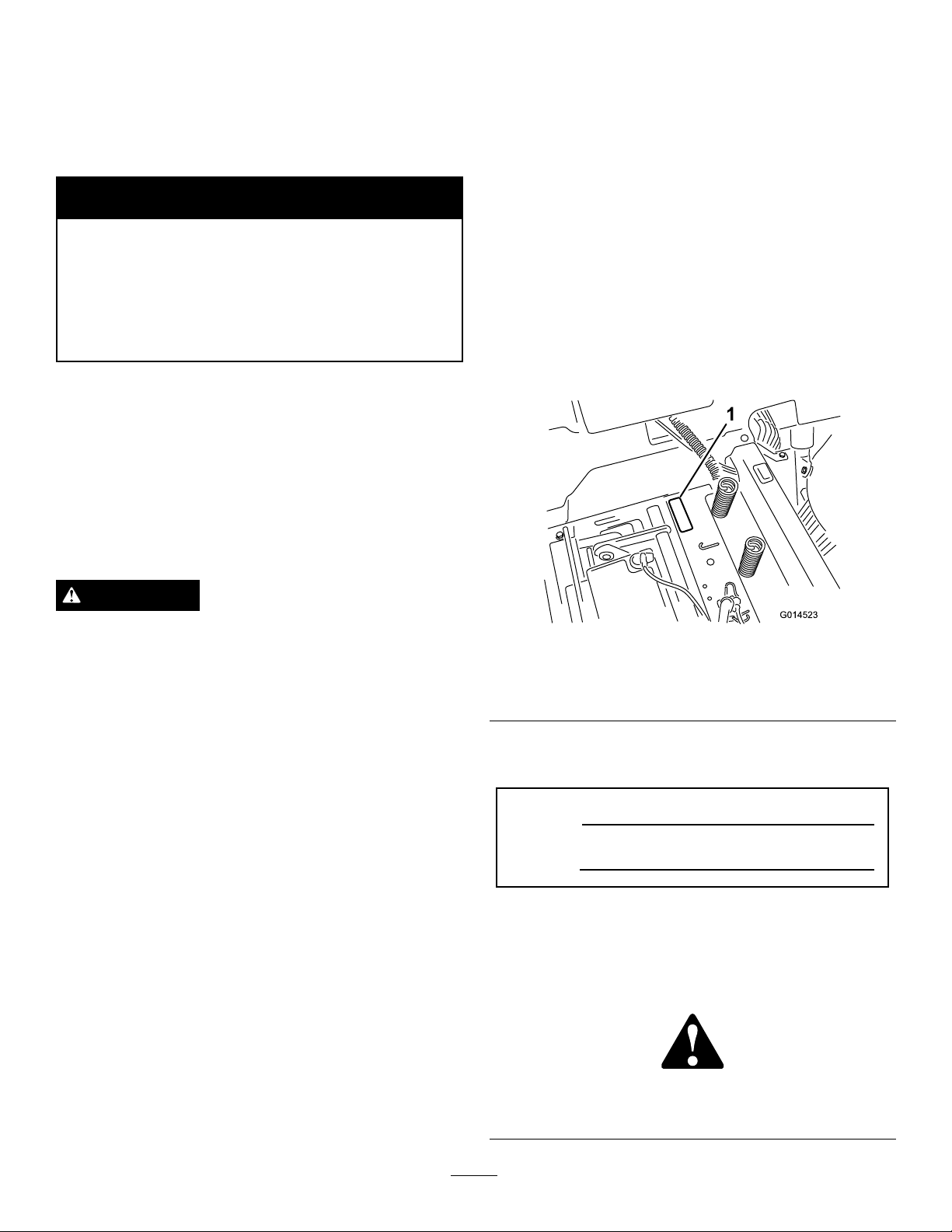
Figure1identiesthelocationofthemodelandserial
numbersontheproduct.Writethenumbersinthe
spaceprovided.
Figure1
Undertheseat
1.Modelandserialnumberplate
Writetheproductmodelandserialnumbersinthespace
below:
ModelNo.
SerialNo.
Thismanualidentiespotentialhazardsandhassafety
messagesidentiedbythesafetyalertsymbol(Figure2),
whichsignalsahazardthatmaycauseseriousinjury
ordeathifyoudonotfollowtherecommended
precautions.
Figure2
©2011—TheToro®Company
8111LyndaleAvenueSouth
Bloomington,MN55420
2
1.Safetyalertsymbol.
Contactusatwww.Toro.com.
PrintedintheUSA.
AllRightsReserved
Page 3

Thismanualusestwootherwordstohighlight
information.Importantcallsattentiontospecial
mechanicalinformationandNoteemphasizesgeneral
informationworthyofspecialattention.
Contents
Introduction.................................................................2
Safety...........................................................................4
SafeOperatingPractices.......................................4
ToroRidingMowerSafety....................................6
SlopeIndicator.....................................................7
SafetyandInstructionalDecals.............................8
ProductOverview......................................................13
Controls.............................................................14
Operation...................................................................15
ThinkSafetyFirst...............................................15
BeforeStarting...................................................17
StartingtheEngine.............................................18
OperatingtheBlades..........................................19
TestingtheSafetyInterlockSystem.....................19
StoppingtheEngine...........................................20
Driving...............................................................20
StoppingtheMachine.........................................22
AdjustingtheHeightofCut................................22
PositioningtheSeat............................................22
AdjustingtheMotionControlLevers..................22
PushingtheMachinebyHand.............................23
GrassDeector..................................................23
OperatingTips...................................................24
Maintenance...............................................................26
RecommendedMaintenanceSchedule(s)................26
PremaintenanceProcedures....................................27
RaisingtheSeat..................................................27
Lubrication.............................................................27
GreasingtheBearings.........................................27
EngineMaintenance...............................................28
ServicingtheAirCleaner....................................28
ServicingtheEngineOil.....................................29
ServicingtheSparkPlug.....................................31
CleaningtheBlowerHousing..............................32
FuelSystemMaintenance.......................................32
ReplacingtheIn-lineFuelFilter..........................32
ElectricalSystemMaintenance................................33
ChargingtheBattery...........................................33
ServicingtheFuses.............................................34
DriveSystemMaintenance.....................................35
CheckingtheTirePressure.................................35
ReleasingtheElectricBrake................................35
MowerMaintenance...............................................36
ServicingtheCuttingBlades...............................36
LevelingtheMowerDeck...................................39
RemovingtheMower.........................................41
MowerBeltMaintenance....................................41
InstallingtheMower...........................................42
ReplacingtheGrassDeector.............................42
Cleaning.................................................................43
WashingtheUndersideoftheMower..................43
Storage.......................................................................44
CleaningandStorage..........................................44
Troubleshooting.........................................................46
Schematics.................................................................48
3
Page 4

Safety
ThismachinemeetsorexceedstheB71.1-2003
specicationsoftheAmericanNationalStandards
Institute,ineffectatthetimeofproduction.
However,improperuseormaintenancebythe
operatororownercanresultininjury.T oreduce
thepotentialforinjury,complywiththesesafety
instructionsandalwayspayattentiontothe
safetyalertsymbol,whichmeansCAUTION,
WARNING,orDANGER-"personalsafety
instruction."Failuretocomplywiththeinstruction
mayresultinpersonalinjuryordeath.
SafeOperatingPractices
Thisproductiscapableofamputatinghandsand
feetandthrowingobjects.Alwaysfollowallsafety
instructionstoavoidseriousinjuryordeath.
ThefollowinginstructionsarefromANSIstandard
B71.1-2003.AllthelanguagewithinthisANSIstandard
appliestothismachine;however,duetotheapplication
ofthestandardacrossmanydifferenttypesofproducts
somestatementscanseemgeneralormisleading.In
theseinstances,Torohasrenedthestatementtoconvey
themeaningofthestandardwhilebettermatching
theproductthisOperator'sManualpertains.Safety
informationinadditiontotheinstructionsfoundin
theANSIstandardbelowcanbefoundinToroRiding
MowerSafetyattheendofthissection.
GeneralOperation
•Read,understand,andfollowallinstructionsin
theoperator'smanualandonthemachinebefore
starting.
•Donotplacehandsorfeetnearrotatingpartsor
underthemachine.Keepclearofthedischarge
openingatalltimes.
•Allowonlyresponsibleadultswhoarefamiliarwith
theinstructionstooperatethemachine.
•Cleartheareaofobjectssuchasrocks,toys,wire,etc.,
whichcouldbepickedupandthrownbytheblade.
•Besuretheareaisclearofotherpeoplebefore
mowing.Stopthemachineifanyoneentersthearea.
•Nevercarrypassengers.
•Donotmowinreverseunlessabsolutelynecessary.
Alwayslookdownandbehindbeforeandwhile
backingup.
•Beawareofthemowerdischargedirectionanddo
notpointitatanyone.Avoiddischargingmaterial
againstawallorobstruction.Materialmayricochet
backtowardtheoperator.Stoptheblade(s)when
crossinggravelsurfaces.
•Donotoperatethemachinewithoutdeector,
dischargecoverorentiregrasscollectionsystemin
placeandworking.
•Bealert,slowdownandusecautionwhenmaking
turns.Lookbehindandtothesidebeforechanging
directions.
•Neverleavearunningmachineunattended.Always
turnoffblades,setparkingbrake,stopengine,and
removekeybeforedismounting.
•Turnoffbladeswhennotmowing.Stoptheengine,
waitforallpartstocometoacompletestop
andremovethekeybeforecleaningthemachine,
removingthegrasscatcheroruncloggingthe
dischargechute.
•Operatethemachineonlyindaylightorgood
articiallight.
•Donotoperatethemachinewhileunderthe
inuenceofalcoholordrugs.
•Watchfortrafcwhenoperatingnearorcrossing
roadways.
•Useextracarewhenloadingorunloadingthe
machineintoatrailerortruck.
•Alwaysweareyeprotectionwhenoperatingthe
mower.
•Dataindicatesthatoperators,age60yearsand
above,areinvolvedinalargepercentageofriding
mower-relatedinjuries.Operatorsshouldevaluate
theirabilitytooperatetheridingmowersafely
enoughtoprotectthemselvesandothersfrom
seriousinjury.
•Alwaysfollowtherecommendationsforany
applicationofcounterweights.
•Lightningcancausesevereinjuryordeath.If
lightningisseenorthunderisheardinthearea,do
notoperatethemachine;seekshelter.
SlopeOperation
Slopesareamajorfactorrelatedtolossofcontroland
tip-overaccidents,whichcanresultinsevereinjuryor
death.Operationonallslopesrequiresextracaution.If
youcannotbackuptheslopeorifyoufeeluneasyonit,
donotmowit.
•Donotmowslopesgreaterthan15degrees.
•Watchforditches,holes,rocks,dips,andrisesthat
changetheoperatingangle,asroughterraincould
overturnthemachine.
4
Page 5

•Choosealowgroundspeedsoyouwillnothaveto
stopwhileoperatingonaslope.
•Donotmowslopeswhengrassiswet.Slippery
conditionsreducetractionandcouldcausesliding
andlossofcontrol.
•Alwayskeepthedrivewheelsengagedwhengoing
downslopes.
•Reducespeedanduseextremecautiononslopes.
•Donotmakesuddenturnsorrapidspeedchanges.
•Removeormarkobstaclessuchasrocks,treelimbs,
etc.fromthemowingarea.Tallgrasscanhide
obstacles.
•Avoidsuddenstartswhenmowinguphillbecausethe
mowermaytipbackwards.
•Beawarethatlossoftractionmayoccurgoing
downhill.Weighttransfertothefrontwheelsmay
causedrivewheelstoslipandcauselossofbraking
andsteering.
•Alwaysavoidsuddenstartingorstoppingonaslope.
Iftireslosetraction,stopthemachine,disengagethe
bladesandproceedslowlyofftheslope.
•Useextremecarewithgrasscatchersorother
attachments.Thesecanchangethestabilityofthe
machineandcauselossofcontrol.
•Donottrytostabilizethemachinebyputtingyour
footontheground.
•Donotmowneardrop-offs,ditches,steepbanks
orwater.Wheelsdroppingoveredgescancause
rollovers,whichmayresultinseriousinjury,death
ordrowning.
•Useawalkbehindmowerand/orahandtrimmer
neardrop-offs,ditches,steepbanksorwater.
Children
Tragicaccidentscanoccuriftheoperatorisnotalertto
thepresenceofchildren.Childrenareoftenattractedto
themachineandthemowingactivity.Neverassumethat
childrenwillremainwhereyoulastsawthem.
•Keepchildrenoutofthemowingareaandunderthe
watchfulcareofanotherresponsibleadult,notthe
operator.
•Bealertandturnthemachineoffifchildrenenter
thearea.
•Beforeandwhilebackingorchangingdirection,look
behind,down,andside-to-sideforsmallchildren.
•Childrenwhohavebeengivenridesinthepastmay
suddenlyappearinthemowingareaforanotherride
andberunoverorbackedoverbythemower.
•Neverallowchildrentooperatethemachine.
•Useextracarewhenapproachingblindcorners,
shrubs,trees,theendofafenceorotherobjectsthat
mayobscurevision.
Towing
Ahitchkitisavailableforthismachineandcanbe
obtainedbycontactinganAuthorizedToroDealer.
Donottowwithoutrstinstallingthismanufacturer
approvedhitch.Thefollowingguidelinesapplywhen
towingwiththeapprovedhitchkitinstalled.
•Towonlywithamachinethathasahitchdesigned
fortowing.Donotattachtowedequipmentexcept
atthehitchpoint.
•Followthemanufacturer'srecommendationfor
weightlimitsfortowedequipmentandtowingon
slopes.
•Neverallowchildrenorothersinorontowed
equipment.
•Onslopes,theweightofthetowedequipmentmay
causelossoftractionandlossofcontrol.
•Travelslowlyandallowextradistancetostop.
Service
SafeHandlingofGasoline:
Toavoidpersonalinjuryorpropertydamage,useextra
carewhenhandlinggasolineandotherfuels.Theyare
ammableandthevaporsareexplosive.
•Extinguishallcigarettes,cigars,pipesandother
sourcesofignition.
•Useonlyanapprovedcontainer.
•Neverremovethegascaporaddfuelwhenthe
engineisrunning.Allowtheenginetocoolbefore
refueling.
•Neverrefuelthemachineindoors.
•Neverstorethemachineorfuelcontainerinside
wherethereisanopename,suchasnearawater
heaterorfurnace.
•Neverllcontainersinsideavehicleoronatruckor
trailerwithaplasticliner.Alwaysplacecontainerson
thegroundawayfromyourvehiclebeforelling.
•Nevercarrychildren,evenwiththebladesoff.They
mayfalloffandbeseriouslyinjuredorinterferewith
safemachineoperation.
•Removegas-poweredequipmentfromthetruck
ortrailerandrefuelitontheground.Ifthisisnot
possible,thenrefuelsuchequipmentwithaportable
5
Page 6

container,ratherthanfromagasolinedispenser
nozzle.
•Keepthenozzleincontactwiththerimofthefuel
tankorcontaineropeningatalltimesuntilthefueling
iscomplete.Donotuseanozzlelock-opendevice.
•Iffuelisspilledonclothing,changeclothing
immediately.
•Neveroverllthefueltank.Replacegascapand
tightensecurely .
GeneralService:
•Neveroperateamachineinsideaclosedarea.Engine
exhaustcontainscarbonmonoxide,whichisan
odorless,deadlypoisonthatcankillyou.
•Keepnutsandboltstight,especiallytheblade
attachmentbolts.Keepequipmentingood
condition.
thebladecontrolswitch,removekeybeforeand
disconnectsparkplugwire(s)performinganyservice,
repairs,maintenanceoradjustments.
•Keephands,feet,hair,andlooseclothingawayfrom
attachmentdischargearea,undersideofmowerand
anymovingpartswhileengineisrunning.
•Donottouchequipmentorattachmentpartswhich
maybehotfromoperation.Allowtocoolbefore
attemptingtomaintain,adjustorservice.
•Batteryacidispoisonousandcancauseburns.Avoid
contactwithskin,eyes,andclothing.Protectyour
face,eyes,andclothingwhenworkingwithabattery.
•Batterygasescanexplode.Keepcigarettes,sparks
andamesawayfrombattery.
•UseonlyToroapprovedattachments.Warrantymay
bevoidedifusedwithunapprovedattachments.
•Nevertamperwithsafetydevices.Checktheir
properoperationregularly.
•Keepthemachinefreeofgrass,leaves,orother
debrisbuild-up.Cleanupoilorfuelspillagefuel
soakeddebris.Allowthemachinetocoolbefore
storing.
•Stopandinspecttheequipmentifyoustrikean
object.Repair,ifnecessary,beforerestarting.
•Nevermakeanyadjustmentsorrepairswiththe
enginerunning.
•Grasscatchercomponentsaresubjecttowear,
damageanddeterioration,whichcouldexpose
movingpartsorallowobjectstobethrown.
Frequentlycheckcomponentsandreplacewith
manufacturers'recommendedparts,whennecessary.
•Mowerbladesaresharpandcancut.Wrapthe
blade(s)orweargloves,anduseextracautionwhen
servicingthem.
•Checkforproperbrakeoperationfrequently.Adjust
andserviceasrequired.
•Ifloadingthemachineontoatrailerortruck,usea
single,full-widthramponly.Therampangleshould
notexceed15degrees.
•Maintainorreplacesafetyandinstructiondecalsas
necessary.
•UseonlygenuineTororeplacementpartstoensure
thatoriginalstandardsaremaintained.
ToroRidingMowerSafety
Thefollowinglistcontainssafetyinformationspecicto
Toroproductsorothersafetyinformationthatyoumust
knowthatmaynotbeincludedintheANSIstandards.
•Stoptheengine,movethemotioncontrolleversto
neutralandoutwardtotheparkposition,disengage
6
Page 7
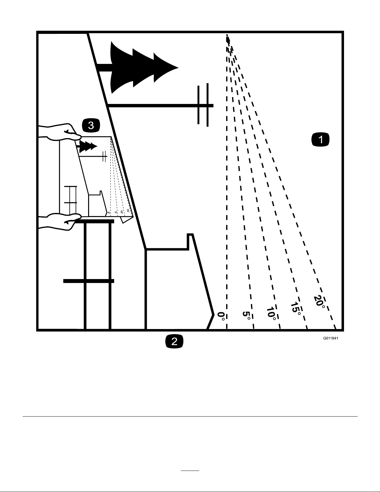
SlopeIndicator
G011841
Figure3
Thispagemaybecopiedforpersonaluse.
1.Themaximumslopeyoucansafelyoperatethemachineonis15degrees.Usetheslopecharttodeterminethedegreeofslope
ofhillsbeforeoperating.Donotoperatethismachineonaslopegreaterthan15degrees.Foldalongtheappropriateline
tomatchtherecommendedslope.
2.Alignthisedgewithaverticalsurface,atree,building,fencepole,etc.
3.Exampleofhowtocompareslopewithfoldededge.
7
Page 8
SafetyandInstructional
Decals
Safetydecalsandinstructionsareeasilyvisibletotheoperatorandarelocatednearanyareaof
potentialdanger.Replaceanydecalthatisdamagedorlost.
93-7009
1.Warning—don'toperatethemowerwiththedeectorupor
removed;keepthedeectorinplace.
2.Cutting/dismembermenthazardofhandorfoot,mower
blade—stayawayfrommovingparts.
110-6691
1.Thrownobjecthazard—keepbystandersasafedistance
fromthemachine.
2.Thrownobjecthazard,mower—donotoperatewithoutthe
deector,dischargecover,orgrasscollectionsystemin
place.
3.Cutting/dismembermentofhandorfoot—stayawayfrom
movingparts.
105-7015
ForModelswith42InchDecks
106-8717
1.Readtheinstructionsbeforeservicingorperforming
maintenance.
2.Checktirepressureevery25operatinghours.
3.Greaseevery25operatinghours.
4.Engine
114-1606
1.Entanglementhazard,belt—keepallguardsinplace.
119-8814
1.Parkingposition4.Neutral
2.Fast5.Reverse
3.Slow
8
Page 9
119-8815
1.Parkingposition4.Neutral
2.Fast5.Reverse
3.Slow
121-2989
119-8871
Certainmodelsonly
1.Bypassleverpositionfor
pushingthemachine
2.Bypassleverpositionfor
operatingthemachine
1.Height-of-cut
9
Page 10
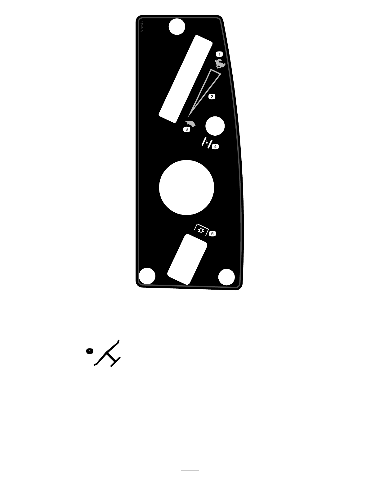
121-0772
1.Fast
2.Continuousvariablesetting5.Powertake-off(PTO),Bladecontrolswitch
3.Slow
4.Choke
Manufacturer'sMark
1.Indicatesthebladeisidentiedasapartfromtheoriginal
machinemanufacturer.
10
Page 11

BatterySymbols
Someorallofthesesymbolsareonyourbattery
1.Explosionhazard
2.Nore,opename,or
smoking.
3.Causticliquid/chemical
burnhazard
4.Weareyeprotection9.Flusheyesimmediately
5.ReadtheOperator's
Manual.
6.Keepbystandersasafe
7.Weareyeprotection;
8.Batteryacidcancause
10.Containslead;donot
distancefromthebattery.
explosivegasescan
causeblindnessandother
injuries
blindnessorsevereburns.
withwaterandgetmedical
helpfast.
discard.
11
Page 12
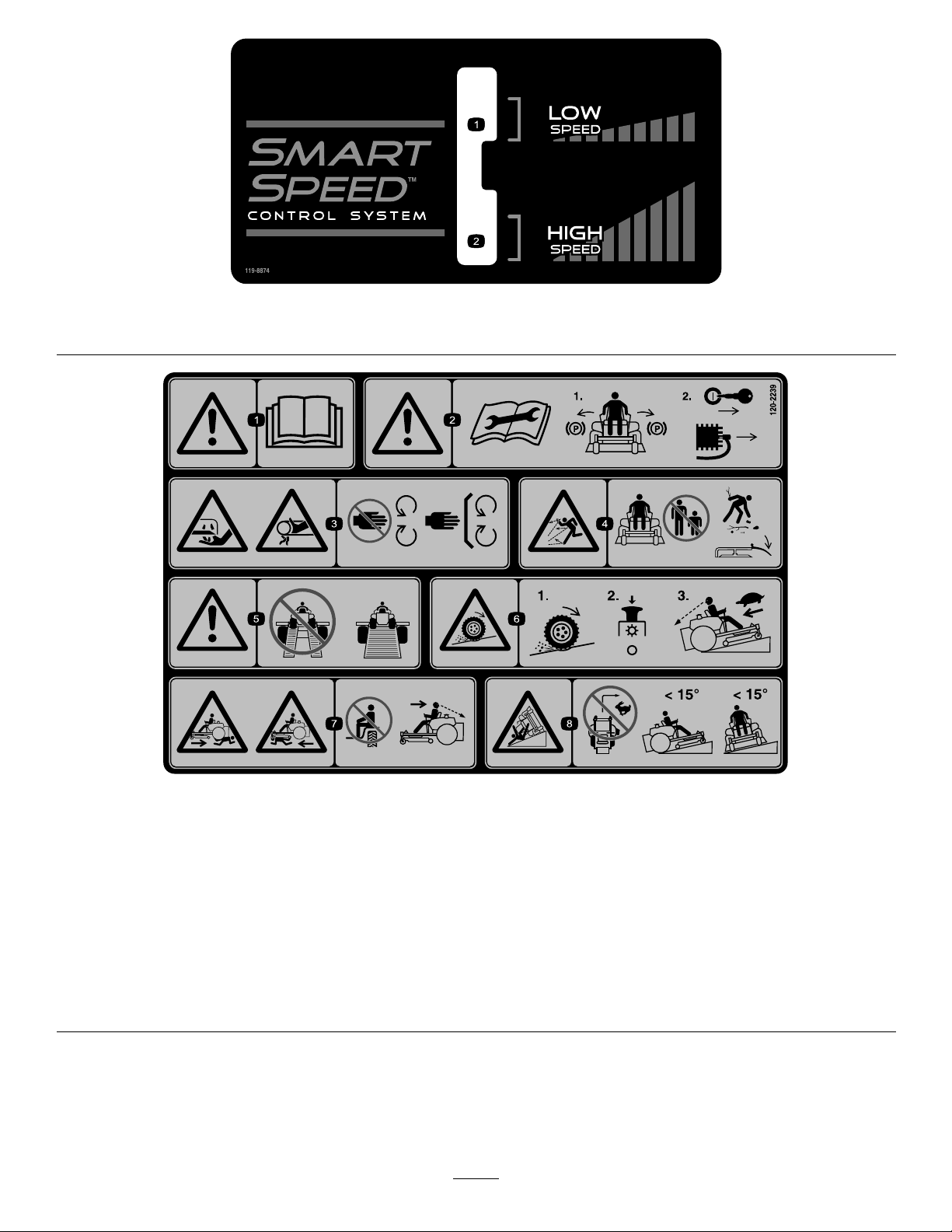
119-8874
1.Lowspeed2.Highspeed
120-2239
1.Warning—readtheOperator'sManual.5.Warning—donotusesplitramps,useafullrampswhen
2.Warning—readtheinstructionsbeforeservicingorperforming
maintenance;movethemotioncontrolleverstothepark
(brake)position,removetheignitionkeyanddisconnectthe
sparkplugwire.
3.Cutting/dismembermenthazard,mowerblade;entanglement
hazard,belt—stayawayfrommovingparts,keepallguards
andshieldsinplace.
4.Thrownobjecthazard—keepbystandersasafedistancefrom
themachine,pickupdebrisbeforeoperating,keepdeector
inplace.
transportingmachine.
6.Lossoftraction/controlhazard,slopes—lossoftraction/control
onaslope,disengagethebladecontrolswitch(PTO),
proceedofftheslopeslowly.
7.Crushing/dismembermenthazardofbystanders,reversing;
crushing/dismembermenthazardofbystanders—donotcarry
passengers,lookbehindanddownwhenreversing.
8.Tippinghazard—donotmowslopesgreaterthan15degrees,
avoidsuddenandsharpturnswhileonslopes.
12
Page 13
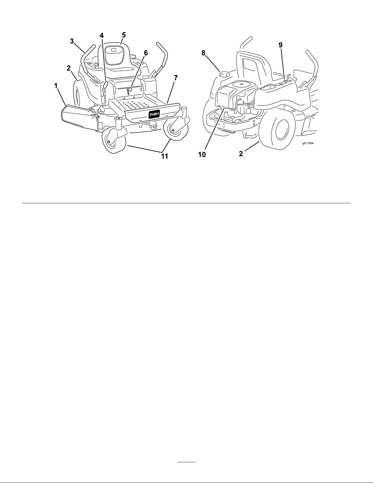
ProductOverview
1
2
3
4
5
6
7
11
8
9
10
2
g017554
Figure4
1.Deector4.Heightofcutlever
2.Reardrivewheel
3.Motioncontrollevers
5.Operatorseat
6.SmartSpeed™lever9.Controlpanel
7.Footrest10.Engine
8.Fueltankcap11.Frontcasterwheel
13
Page 14
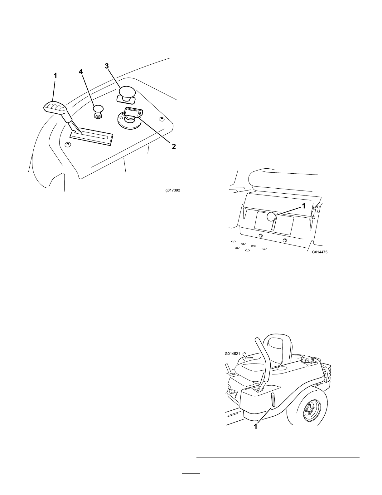
Controls
G014475
1
G014521
1
BecomefamiliarwithallofthecontrolsinFigure4and
Figure5beforeyoustarttheengineandoperatethe
machine.
Figure5
ControlPanel
MotionControlLeversandPark
Position
Themotioncontrolleversarespeedsensitivecontrolsof
independentwheelmotors.Movingaleverforwardor
backwardturnsthewheelonthesamesideforwardorin
reverse;wheelspeedisproportionaltotheamountthe
leverismoved.Movethecontrolleversoutwardfrom
thecentertotheparkpositionandexitthemachine
Figure16).Alwayspositionthemotioncontrollevers
(
intotheparkpositionwhenyoustopthemachineor
leaveitunattended.
SmartSpeed™ControlSystemLever
TheSmartSpeed™ControlSystemlever,locatedbelow
theoperatingposition,givestheoperatorachoiceto
drivethemachineattwospeedranges,highandlow
(Figure6).
1.Throttle3.Bladecontrolswitch
2.Ignitionswitch
(powertake-off)
4.Choke
IgnitionSwitch
Theignitionswitchhasthreepositions,Off,Runand
Start.ThekeywillturntoStartandmovebackto
Runuponrelease.TurningthekeytotheOffposition
willstoptheengine;however,alwaysremovethekey
whenleavingthemachinetopreventsomeonefrom
accidentallystartingtheengine(
Figure5).
ThrottleControl
Thethrottlecontrolstheenginespeedandithasa
continuousvariablesettingfromSlowtoFast(Figure5).
ChokeControl
PullupontheChokecontroluntilitstopstochokethe
engine(Figure5).PushdownontheChokecontrolfor
normalengineoperation
Figure6
1.Smartspeedlever
FuelWindow
Thefuelwindowlocatedonthelefthandsideofthe
machinecanbeusedtoverifythepresenceofgasoline
inthetank(Figure7).
BladeControlSwitch(PowerTake-Off)
Thebladecontrolswitch,representedbyapower
take-off(PTO)symbol,engagesanddisengagespower
tothemowerblades(Figure5).
Figure7
1.Fuelpresencewindow
14
Page 15

Height-of-CutLever
Theheightofcutleverallowstheoperatortolower
andraisethedeckfromtheseatedposition.Whenthe
leverismovedup,towardtheoperatorthedeckisraised
fromthegroundandwhenmoveddown,awayfromthe
operatoritisloweredtowardtheground.Onlyadjustthe
heightofcutwhilemachineisnotmoving(Figure20).
Operation
Note:Determinetheleftandrightsidesofthe
machinefromthenormaloperatingposition.
ThinkSafetyFirst
OperatingSafety
Pleasecarefullyreadallofthesafetyinstructionsand
decalsinthesafetysection.Knowingthisinformation
couldhelpyou,yourfamily,petsorbystandersavoid
injury.
DANGER
Mowingonwetgrassorsteepslopescancause
slidingandlossofcontrol.
Wheelsdroppingoveredgescancauserollovers,
whichmayresultinseriousinjury,deathor
drowning.
Alossoftractionisalossofsteeringcontrol.
Toavoidlossofcontrolandpossibilityofrollover:
•Donotmowneardrop-offsornearwater.
•Donotmowslopesgreaterthan15degrees.
•Reducespeedanduseextremecautionon
slopes.
•Whenmowingslopes,graduallyworkfrom
lowertohigherareasontheincline.
•Avoidsuddenturnsorrapidspeedchanges.
•Turnup,intoaninclinewhenchanging
directionsonslopes.Turningdowntheslope
reducestraction.
•Attachmentschangethehandling
characteristicsofthemachine.Use
extracautionwhenusingattachmentswiththe
machine.
15
Page 16
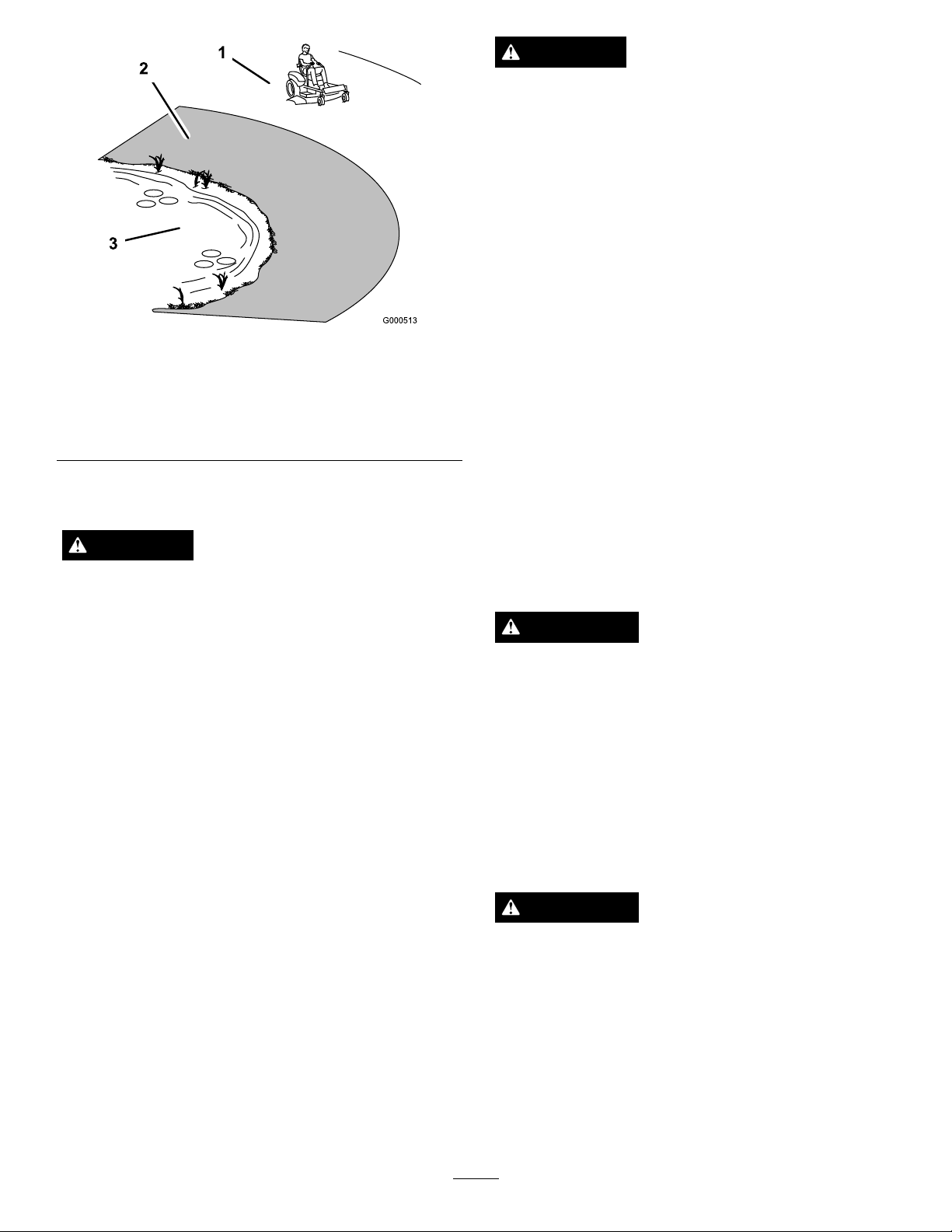
Figure8
1.SafeZone-usethe
TimeCutterhere
2.Usewalkbehindmower
and/orhandtrimmernear
drop-offsandwater.
3.Water
FuelSafety
DANGER
Incertainconditions,gasolineisextremely
ammableandhighlyexplosive.Areorexplosion
fromgasolinecanburnyouandothersandcan
damageproperty.
•Fillthefueltankoutdoors,inanopenarea,
whentheengineiscold.Wipeupanygasoline
thatspills.
•Neverllthefueltankinsideanenclosedtrailer.
•Donotllthefueltankcompletelyfull.Add
gasolinetothefueltankuntilthefuelreaches
thebaseofthellerneck.Thisemptyspacein
thetankallowsgasolinetoexpand.
•Neversmokewhenhandlinggasoline,andstay
awayfromanopenameorwheregasoline
fumesmaybeignitedbyaspark.
•Storegasolineinanapprovedcontainerand
keepitoutofthereachofchildren.Neverbuy
morethana30-daysupplyofgasoline.
•Donotoperatewithoutentireexhaustsystem
inplaceandinproperworkingcondition.
DANGER
Incertainconditionsduringfueling,static
electricitycanbereleasedcausingasparkwhich
canignitethegasolinevapors.Areorexplosion
fromgasolinecanburnyouandothersandcan
damageproperty.
•Alwaysplacegasolinecontainersontheground
awayfromyourvehiclebeforelling.
•Donotllgasolinecontainersinsideavehicle
oronatruckortrailerbedbecauseinterior
carpetsorplastictruckbedlinersmayinsulate
thecontainerandslowthelossofanystatic
charge.
•Whenpractical,removegas-powered
equipmentfromthetruckortrailerandrefuel
theequipmentwithitswheelsontheground.
•Ifthisisnotpossible,thenrefuelsuch
equipmentonatruckortrailerfromaportable
container,ratherthanfromagasolinedispenser
nozzle.
•Ifagasolinedispensernozzlemustbeused,
keepthenozzleincontactwiththerimofthe
fueltankorcontaineropeningatalltimesuntil
fuelingiscomplete.
WARNING
Gasolineisharmfulorfatalifswallowed.
Long-termexposuretovaporscancauseserious
injuryandillness.
•Avoidprolongedbreathingofvapors.
•Keepfaceawayfromnozzleandgastankor
conditioneropening .
•Keepgasawayfromeyesandskin.
UnderstandingtheSafetyInterlock
System
WARNING
Ifsafetyinterlockswitchesaredisconnectedor
damagedthemachinecouldoperateunexpectedly
causingpersonalinjury.
•Donottamperwiththeinterlockswitches.
•Checktheoperationoftheinterlockswitches
dailyandreplaceanydamagedswitchesbefore
operatingthemachine.
Thesafetyinterlocksystemisdesignedtopreventthe
enginefromstartingunless:
16
Page 17

•Thebladesaredisengaged.
G014474
1
2
3
4
5
6
G014895
1
2
3
4
•Themotioncontrolleversareintheparkposition.
Thesafetyinterlocksystemalsoisdesignedtostopthe
enginewheneverthecontrolleversareoutofthepark
positionandyourisefromtheseat.
Overllingmayresultinfuelleakageordamageto
theengineoremissionsystem.
1.Cleanaroundthefueltankcapandremovethecap.
Note:Y oucanusethefuelwindowtoverify
thepresenceofgasolinebeforellingthetank
(Figure9).
BeforeStarting
RecommendedFuel
•Forbestresults,useonlyclean,fresh,unleaded
gasolinewithanoctaneratingof87orhigher
((R+M)/2ratingmethod).
•Oxygenatedfuelwithupto10%ethanolor15%
MTBEbyvolumeisacceptable.
•DoNotuseethanolblendsofgasoline(suchasE15
orE85)withmorethan10%ethanolbyvolume.
Performanceproblemsand/orenginedamagemay
resultwhichmaynotbecoveredunderwarranty.
•DoNotusegasolinecontainingmethanol.
•DoNotstorefueleitherinthefueltankorfuel
containersoverthewinterunlessafuelstabilizeris
used.
•DoNotaddoiltogasoline.
UsingStabilizer/Conditioner
Useafuelstabilizer/conditionerinthemachineto
providethefollowingbenets:
2.Slowlyaddregular,unleadedgasolineuntilthefuel
reachesthebaseofthellerneck(
Figure9
1.Fueltankcap
2.Fillopening5.Fuelwindow
3.Fillerneck
4.Baseofllerneck,DO
Figure9).
NOTFILLP ASTHERE
•Keepsgasolinefreshduringstorageof90daysor
less.Forlongerstorageitisrecommendedthatthe
fueltankbedrained.
•Cleanstheenginewhileitruns.
•Eliminatesgum-likevarnishbuildupinthefuel
system,whichcauseshardstarting.
Addthecorrectamountofgasstabilizer/conditioner
tothegas.
Note:Afuelstabilizer/conditionerismosteffective
whenmixedwithfreshgasoline.Tominimizethe
chanceofvarnishdepositsinthefuelsystem,usefuel
stabilizeratalltimes.
FillingtheFuelTank
Makesuretheengineisshutoffandthemotion
controlsareintheparkposition.Tankmaximum
capacityis2.9gallons.
Important:DoNotoverllfueltank.Fillthe
fueltanktothebottomofthellerneck.The
emptyspaceinthetankallowsthefueltoexpand.
Figure10
1.Fillopening3.Fuel
2.Baseofllerneck,DO
NOTFILLP ASTHERE
4.Emptyspaceforfuel
expansion.
Important:DoNotoverllfueltank.Fill
thefueltanktothebottomofthellerneck.
Theemptyspaceinthetankallowsthefuelto
expand.Overllingmayresultinfuelleakage
ordamagetotheengineoremissionsystem.
3.Installthefueltankcapsecurelyandtightenuntilit
“clicks”.Wipeupanygasolinethatmayhavespilled.
17
Page 18

CheckingtheEngineOilLevel
Beforeyoustarttheengineandusethemachine,check
theoillevelintheenginecrankcase;refertoChecking
theOilLevelintheEngineMaintenancesection.
StartingtheEngine
1.Sitdownontheseatandmovethemotioncontrols
outwardtotheparkposition.
2.Disengagethebladesbymovingthebladecontrol
switchtoOff(Figure11)
Figure12
Figure11
1.Controlpanel2.Bladecontrolswitch—Off
position
3.PullupontheChokecontrolbeforestartingacold
engine(Figure12).
Note:Awarmorhotenginemaynotrequire
choking.
1.Controlpanel4.Continuousvariable
2.Throttle
3.Fast
setting
5.Slow
6.Chokecontrol
4.TurntheignitionkeytoStarttoenergizethestarter.
Whentheenginestarts,releasethekey(Figure13).
Important:Donotengagethestarterformore
than10secondsatatime.Iftheenginefails
tostart,allowa60secondcool-downperiod
betweenattempts.Failuretofollowthese
instructionscandamagethestartermotor.
18
Page 19

Figure14
Figure13
1.Controlpanel
2.Ignitionkey—runposition
3.Ignitionkey—startposition
4.Off
5.Run
6.Start
7.Chokecontrol
5.Aftertheenginestarts,pushdownontheChoke
control(Figure13).Iftheenginestallsorhesitates,
pullupontheChokecontrolandlettheenginerun
forafewseconds.ThenpushdownontheChoke
control.Repeatthisasrequired.
OperatingtheBlades
Thebladecontrolswitch,representedbyapower
take-off(PTO)symbol,engagesanddisengagespower
tothemowerblades.Thisswitchcontrolspowertoany
attachmentsthatdrawpowerfromtheengine,including
themowerdeckandcuttingblades.
1.Controlpanel2.Bladecontrolswitch—On
position
DisengagingtheBlades
Pushdownonthebladecontrolswitchtomoveitto
theOffpositionanddisengagetheblades(Figure15).
EngagingtheBlades
Important:Donotengagethebladeswhenparked
intallgrass.Beltorclutchdamagecanoccur.
1.Releasepressureonthemotioncontrolleversand
placethemachineinneutral.
2.MovethethrottletotheFastposition.
Note:Alwaysengagethebladeswiththethrottle
intheFastposition.
3.Pulluponthebladecontrolswitchtomoveittothe
Onpositionandengagetheblades(Figure14).
Figure15
1.Controlpanel2.Bladecontrolswitch—Off
TestingtheSafetyInterlock
System
Testthesafetyinterlocksystembeforeyouusethe
machineeachtime.Ifthesafetysystemdoesnot
19
Page 20

operateasdescribedbelow,haveanAuthorizedService
Dealerrepairthesafetysystemimmediately.
1.Whilesittingontheseat,withthecontrolleversin
parkposition,andmovethebladecontrolswitchto
On.Trystartingtheengine;theengineshouldnot
crank.
2.Whilesittingontheseat,movethebladecontrol
switchtoOff.Moveeithermotioncontrollever
tothecenter,unlockedposition.Trystartingthe
engine;theengineshouldnotcrank.Repeatwith
theothermotioncontrollever.
3.Whilesittingontheseat,movethebladecontrol
switchtoOff,andlockthemotioncontrolleversin
theparkposition.Starttheengine.Whiletheengine
isrunning,engagethebladecontrolswitch,andrise
slightlyfromtheseat;theengineshouldstop.
4.Whilesittingontheseat,movethebladecontrol
switchtoOff,andlockthemotioncontrollevers
intheparkposition.Starttheengine.Whilethe
engineisrunning,movethemotioncontrollevers
tothecenter,unlockedposition,engagetheblade
controlswitch,andriseslightlyfromtheseat;the
engineshouldstop.
Thethrottlecontrolregulatestheenginespeedas
measuredinrpm(revolutionsperminute).Placingthe
throttlecontrolintheFastpositioncanbebestfor
performance.Formostapplications,operatinginthe
fullthrottlepositionisdesirable.
StoppingtheEngine
1.Disengagethebladesbymovingthebladecontrol
switchtoOff(Figure15).
2.MovethethrottlelevertobetweentheFastposition
(Figure12).
3.TurntheignitionkeytoOff(Figure13)andremove
thekey .
Driving
Drivingthemachinebenetsfromanunderstandingof
whatzeroturnradiusmowermeans.Thedrivewheels
turnindependently,poweredbyhydraulicmotorson
eachaxle;henceonesidecanturninreversewhile
theotherturnsforwardcausingthemachinetospin
ratherthanturn.Thisvastlyimprovesthemachine
maneuverabilitybutmayrequiresomeadjustmentif
theoperatorisunfamiliar.
WARNING
Themachinecanspinveryrapidly.Theoperator
maylosecontrolofthemachineandcausepersonal
injuryordamagetothemachine.
Figure16
1.Park(brake)position
2.Centerunlockposition
3.Forward
4.Backward
UsingtheSmartSpeed™Control
System
TheSmartSpeed™ControlSystemlever,located
belowtheoperatingposition(Figure17),givesthe
operatorachoicetodrivethemachineattwoground
speedranges,highandlow .
•Usecautionwhenmakingturns.
•Slowthemachinedownbeforemakingsharp
turns.
20
Page 21

G014475
1
1.Smartspeedlever
G008952
G008953
Tochangespeeds:
Figure17
1.Movethemotioncontrolleverstoneutraland
outwardtotheparkposition;disengagetheblade
controlswitch.
WARNING
Removingyourhandsfromthemotioncontrol
leverswhilethemachineisinmotioncanresult
inalossofcontrolcausingharmtoyouor
bystanders.
Alwaysstopthemachineandmovethemotion
controlleverstotheparkpositionbefore
adjustingtheSmartSpeed™ControlSystem.
2.Adjustthelevertothedesiredposition.
Forward
1.Movetheleverstothecenter,unlockedposition.
2.Togoforward,slowlypushthemotioncontrol
leversforward(Figure16).
Figure18
Togostraight,applyequalpressuretobothmotion
controllevers(Figure16).
Toturn,releasepressureonthemotioncontrollever
towardthedirectionyouwanttoturn(
Figure16).
Thefartheryoumovethemotioncontrolleversin
eitherdirection,thefasterthemachinewillmovein
thatdirection.
Tostop,pullthemotioncontrolleverstoneutral.
Backward
1.Movetheleverstothecenter,unlockedposition.
2.Togobackward,lookbehindyouanddownas
youslowlypullthemotioncontrolleversrearward
Figure19).
(
Figure19
21
Page 22

Togostraight,applyequalpressuretobothmotion
G014476
1
2
3
G014477
1
controllevers(Figure19).
Toturn,releasethepressureonthemotioncontrol
levertowardthedirectionyouwanttoturn.
Tostop,pushthemotioncontrolleverstoneutral.
StoppingtheMachine
Thetransportpositionisthehighestheight-of-cut
positionorcuttingheight4.5inch[115mm](
Figure20).
PositioningtheSeat
Theseatcanmoveforwardandbackward.Positionthe
seatwhereyouhavethebestcontrolofthemachine
andaremostcomfortable.
Tostopthemachine,movethemotioncontrolleversto
neutralandoutwardtotheparkposition,disengagethe
bladecontrolswitch,ensurethethrottleisinthefast
position,andturntheignitionkeytoOff.Remember
toremovethekeyfromtheignitionswitch.
WARNING
Childrenorbystandersmaybeinjuredifthey
moveorattempttooperatethemowerwhileitis
unattended.
Alwaysremovetheignitionkeyandmovethe
motioncontrolleversoutwardtotheparkposition
whenleavingthemachineunattended,evenifjust
forafewminutes.
AdjustingtheHeightofCut
Height-of-cutiscontrolledbytheleverlocatedtothe
rightoftheoperatingposition(Figure20).
1.Raisetheseatandloosentheadjustmentboltsjust
enoughthatseatcanmove(
Figure21
1.Adjustmentbolt
2.Movetheseattothedesiredpositionandtighten
thebolts.
Figure21).
1.Height-of-cutlever3.4.5inch(115mm),
2.Height-of-cutpositions
1.Pullupandinwardonthelevertomoveittothe
desiredcuttingposition.
2.Onceatthedesiredcuttingposition,slowlylower
theleveruntilitengagestheposition.
Figure20
Transportposition
AdjustingtheMotionControl
Levers
AdjustingtheHeight
Themotioncontrolleverscanbeadjustedhigheror
lowerformaximumoperatorcomfort.
1.Removethe2boltsholdingthecontrollevertothe
controlarmshaft(
2.Movethecontrollevertothenextsetofholes.
Securetheleverwiththe2bolts(
Figure22).
Figure22).
22
Page 23

4
1
2
G014970
3
Figure22
g017303
1 2
3
1.Controlarmshaft3.Slotted,upperhole
2.Controllever
4.Bolt
3.Repeattheadjustmentfortheoppositecontrol
lever.
AdjustingtheTilt
5.Movethemotioncontrolleversinwardtothe
neutralpositionandturntheignitionkeytotherun
position.Donotstartthemachine.
Themachineisnowabletobepushedbyhand.
Themotioncontrolleverscanbetiltedforeoraftfor
maximumoperatorcomfort.
1.Loosentheupperboltholdingthecontrolleverto
thecontrolarmshaft.
2.Loosenthelowerboltjustenoughtopivotthe
controlleverforeoraft(Figure22).Tightenboth
boltstosecurethecontrolinthenewposition.
3.Repeattheadjustmentfortheoppositecontrol
lever.
PushingtheMachinebyHand
Important:Alwayspushthemachinebyhand.
Nevertowthemachinebecausedamagemay
occur.
Thismachinehasanelectricbrakemechanismandto
pushthemachinetheignitionkeyneedstobeinthe
Runposition.Thebatteryneedstobechargedand
functioningfortheelectricbraketobedisengage.
Figure23
1.Bypassleverlocations
2.Leverpositionfor
operatingthemachine
3.Leverpositionforpushing
themachine
6.Whennished,ensurethekeyhasbeenreturned
totheStoppositiontoavoiddrainingthebattery
charge.
Ifthemachinefailstomovetheelectricbrake
maystillbeengaged.Ifnecessarytheelectric
brakecanbereleasedmanually.Refertothe
ReleasingtheElectricBrake(page35)procedurein
DriveMaintenance.
ToOperatetheMachine
Movethebypassleversrearwardthroughthekeyhole
anddowntolocktheminplaceasshowninFigure23.
Ensurethisisdoneforeachlever.
ToPushtheMachine
1.Parkthemachineonalevelsurfaceanddisengage
thebladecontrolswitch.
2.Movethemotioncontrolleversoutwardtopark
position,stoptheengine,andwaitforallmoving
partstostopbeforeleavingtheoperatingposition.
3.Locatethebypassleversontheframeonbothsides
oftheengine.
4.Movethebypassleversforwardthroughthekey
holeanddowntolocktheminplaceasshown
in
Figure23.Ensurethisisdoneforeachlever.
GrassDeector
Themowerhasahingedgrassdeectorthatdisperses
clippingstothesideanddowntowardtheturf.
23
Page 24

DANGER
Withoutthegrassdeector,dischargecover,or
completegrasscatcherassemblymountedin
place,youandothersareexposedtobladecontact
andthrowndebris.Contactwithrotatingmower
blade(s)andthrowndebriswillcauseinjuryor
death.
Cut1/3oftheGrassBlade
Itisbesttocutonlyabout1/3ofthegrassblade.
Cuttingmorethanthatisnotrecommendedunless
grassissparse,oritislatefallwhengrassgrowsmore
slowly.
MowingDirection
•Neverremovethegrassdeectorfromthe
mowerbecausethegrassdeectorroutes
materialdowntowardtheturf.Ifthe
grassdeectoriseverdamaged,replaceit
immediately.
•Neverputyourhandsorfeetunderthemower.
•Nevertrytocleardischargeareaormower
bladesunlessyoumovethebladecontrolswitch
toOffandrotatetheignitionkeytoOff.Also
removethekeyandpullthewireoffthespark
plug(s).
OperatingTips
FastThrottleSetting
Forbestmowingandmaximumaircirculation,operate
theengineattheFastposition.Airisrequiredto
thoroughlycutgrassclippings,sodonotsetthe
height-of-cutsolowastototallysurroundthemower
byuncutgrass.Alwaystrytohaveonesideofthe
mowerfreefromuncutgrass,whichallowsairtobe
drawnintothemower.
UsingtheSmartSpeed™Control
System
Alternatemowingdirectiontokeepthegrassstanding
straight.Thisalsohelpsdisperseclippingswhich
enhancesdecompositionandfertilization.
MowatCorrectIntervals
Normally,moweveryfourdays.Butremember,
grassgrowsatdifferentratesatdifferenttimes.So
tomaintainthesamecuttingheight,whichisagood
practice,mowmoreofteninearlyspring.Asthegrass
growthrateslowsinmidsummer,mowlessfrequently.
Ifyoucannotmowforanextendedperiod,rstmow
atahighcuttingheight;thenmowagaintwodayslater
atalowerheightsetting.
AvoidCuttingTooLow
Ifthecuttingwidthofthemoweriswiderthanthe
moweryoupreviouslyused,raisethecuttingheightto
ensurethatuneventurfisnotcuttooshort.
LongGrass
Ifthegrassiseverallowedtogrowslightlylongerthan
normal,orifitcontainsahighdegreeofmoisture,raise
thecuttingheighthigherthanusualandcutthegrassat
thissetting.Thencutthegrassagainusingthelower,
normalsetting.
TheSmartSpeed™ControlSystemlever,located
belowtheoperatingposition,givestheoperatora
choicetodrivethemachineattwospeedranges,high
andlow .Anoperatorcanbenetfromthelower
speedsettingwhenmaneuveringthemachineintight
spacesoroperatingarounddelicatelandscapes.The
lowsettingcanalsobeusedtooperatethemachineat
ahighthrottlesettingandbladespeedwhilestillbeing
abletoreducegroundspeedtoincreasequalityofcut.
CuttingaLawnfortheFirstTime
Cutgrassslightlylongerthannormaltoensurethatthe
cuttingheightofthemowerdoesnotscalpanyuneven
ground.However,thecuttingheightusedinthepastis
generallythebestonetouse.Whencuttinggrasslonger
thansixinchestall,youmaywanttocutthelawntwice
toensureanacceptablequalityofcut.
WhenStopping
Ifthemachine'sforwardmotionmustbestoppedwhile
mowing,aclumpofgrassclippingsmaydropontoyour
lawn.Toavoidthis,moveontoapreviouslycutarea
withthebladesengaged.
KeeptheUndersideoftheMower
Clean
Cleanclippingsanddirtfromtheundersideofthe
moweraftereachuse.Ifgrassanddirtbuildupinside
themower,cuttingqualitywilleventuallybecome
unsatisfactory.
BladeMaintenance
Maintainasharpbladethroughoutthecuttingseason
becauseasharpbladecutscleanlywithouttearingor
24
Page 25

shreddingthegrassblades.Tearingandshreddingturns
grassbrownattheedges,whichslowsgrowthand
increasesthechanceofdisease.Checkthecutterblades
dailyforsharpness,andforanywearordamage.File
downanynicksandsharpenthebladesasnecessary.If
abladeisdamagedorworn,replaceitimmediatelywith
agenuineTororeplacementblade.
25
Page 26

Maintenance
Note:Determinetheleftandrightsidesofthemachinefromthenormaloperatingposition.
RecommendedMaintenanceSchedule(s)
MaintenanceService
Interval
Beforeeachuseordaily
Every25hours
Every50hours
Every100hours
Every200hours
Every500hours
Beforestorage
MaintenanceProcedure
•Checkthesafetyinterlocksystem.
•Checktheaircleanerfordirty ,looseordamagedparts.
•Checktheengineoillevel.
•Checkairintakeandcoolingareas,cleanasnecessary.
•Checkthecuttingblades.
•Inspectthegrassdeectorfordamage
•Cleanthemowerhousing.
•Greasealllubricationpoints.
•Checktirepressure.
•Checkthebeltsforwear/cracks.
•Servicethepaperelement.(moreoftenunderextremelydusty ,dirtyconditions)
•Replacethepaperelement.(moreoftenunderextremelydusty ,dirtyconditions)
•Changetheengineoilandlter.
•Cleantheblowerhousing(moreoftenunderextremelydusty,dirtyconditions).
•Replacethein-linefuellter
•Checksparkplug(s)conditionandgap.
•Replacethesparkplug(s).
•Chargethebatteryanddisconnectbatterycables.
•Performallmaintenanceprocedureslistedabovebeforestorage.
•Paintanychippedsurfaces.
Important:Refertoyourengineoperator'smanualforadditionalmaintenanceprocedures.
CAUTION
Ifyouleavethekeyintheignitionswitch,someonecouldaccidentlystarttheengineandseriouslyinjure
youorotherbystanders.
Removethekeyfromtheignitionanddisconnectthewirefromthesparkplugbeforeyoudoany
maintenance.Setthewireasidesothatitdoesnotaccidentallycontactthesparkplug.
26
Page 27

Premaintenance
1
G014522
Lubrication
Procedures
GreasingtheBearings
RaisingtheSeat
Makesurethemotioncontrolleversarelockedinthe
parkposition.Lifttheseatforward.
Thefollowingcomponentscanbeaccessedbyraising
theseat:
•Serialplate
•Servicedecal
•Seatadjustmentbolts
•Fuellter
•Batteryandbatterycables
ServiceInterval:Every25hours—Greaseall
lubricationpoints.
GreaseType:No.2GeneralPurposeLithiumBase
Grease
1.Parkthemachineonalevelsurfaceanddisengage
thebladecontrolswitch.
2.Movethemotioncontrolleversoutwardtothe
parkposition,stoptheengine,removethekey,and
waitforallmovingpartstostopbeforeleavingthe
operatingposition.
3.Cleanthegreasettings(
witharag.Makesuretoscrapeanypaintoffofthe
frontofthetting(s).
Figure24andFigure25)
1.Frontcastertire
1.Readtheinstructions
beforeservicingor
performingmaintenance.
2.Checktirepressureevery
25operatinghours.
27
Figure24
Figure25
Locatedontheseatpanunderside
3.Greaseevery25operating
hours.
4.Engine
Page 28

4.Connectagreaseguntoeachtting(Figure24and
Figure25).Pumpgreaseintothettingsuntilgrease
beginstooozeoutofthebearings.
5.Wipeupanyexcessgrease.
EngineMaintenance
ServicingtheAirCleaner
ServiceInterval:Beforeeachuseordaily—Checkthe
aircleanerfordirty,looseordamaged
parts.
Thisengineisequippedwithareplaceable,highdensity
paperaircleanerelement.Checktheaircleanerdailyor
beforestartingtheengine.Checkforabuildupofdirt
anddebrisaroundtheaircleanersystem.Keepthisarea
clean.Alsocheckforlooseordamagedcomponents.
Replaceallbentordamagedaircleanercomponents.
Note:Operatingtheenginewithlooseordamagedair
cleanercomponentscouldallowunlteredairintothe
enginecausingprematurewearandfailure.
Note:Servicetheaircleanermoreoftenunder
extremelydusty,dirtyconditions.
28
Page 29

G005187
1
2
3
4
carefully;donotuseifthesealingsurfacesarebent
g017552
0
0
50
SAE 30
ordamaged.
4.Cleantheaircleanerbaseasrequiredandcheck
condition.
5.Installthepaperelementontotheaircleanerbase.
Securewiththelatch.
6.Closetheaircleanercoverdoor.
ServicingtheEngineOil
OilType:Detergentoil(APIserviceSJorhigher)
CrankcaseCapacity:1.7qt(1.6l)whenthelteris
changed
Viscosity:Seethetablebelow .
Figure26
1.Aircleanercover3.Paperelement
2.Aircleanerlatch4.Aircleanerbase
CheckingtheOilLevel
Figure27
ServiceInterval:Beforeeachuseordaily—Checkthe
ServicingPaperElement
engineoillevel.
1.Parkthemachineonalevelsurface,disengagethe
element.(moreoftenunderextremely
ServiceInterval:Every50hours—Servicethepaper
bladecontrolswitch,stoptheengine,andremove
thekey .
dusty,dirtyconditions)
Every100hours—Replacethepaper
element.(moreoftenunderextremely
dusty,dirtyconditions)
1.Opentheaircleanercoverdoorontheblower
housingtoaccesstheaircleanerelement(
Figure26).
2.Unhookthelatchandremovetheaircleanerelement
(
Figure26).
3.Gentlytapthepaperelementtodislodgedirt.Do
2.Makesuretheengineisstopped,level,andiscoolso
theoilhashadtimetodrainintothesump.
3.Tokeepdirt,grassclippings,etc.,outoftheengine,
cleantheareaaroundtheoilllcap/dipstickbefore
removingit.
4.Unscrewandremovethedipstick;wipeoiloff
Figure28).Reinsertthedipstickintothetubeand
(
restthecaponthetube.Donotscrewthecaponto
thetube.
notwashthepaperelementorusepressurized
air,asthiswilldamagetheelement.Replaceadirty,
bent,ordamagedelement.Handlethenewelement
29
Page 30

ADD FULL
G005188
1
2
3
4
Figure28
g017606
1
2
3
1.Oildipstick3.Oillevel—Fullmark
2.Fillertube
4.Oillevel—Addmark
5.Pullthedipstickoutandchecktheoillevel.
(Figure28).
2.Disengagethebladecontrolswitchandmovethe
motioncontrolsoutwardtotheparkposition.
3.Stoptheengine,removethekey ,andwaitforall
movingpartstostopbeforeleavingtheoperating
position.
4.Locatetheoildrainhoseontheleftsideofthe
engine.Thedrainplugisattachedtothedrainhose
Figure29).Cleantheareaaroundtheoildrainplug
(
andtheoildrainhose.
5.Placeapanunderneathmachinedirectlybelowthe
oildrainhoseasshowninFigure29.
Theoillevelshouldbeupto,butnotover,the
“FULL”or“F”markonthedipstick
6.Ifthelevelislow,addoilofthepropertype,uptothe
“FULL”or“F”markonthedipstick.Alwayscheck
thelevelwiththedipstickbeforeaddingmoreoil.
Note:Topreventextensiveenginewearordamage,
alwaysmaintaintheproperoillevelinthecrankcase.
Neveroperatetheenginewiththeoillevelbelowthe
“ADD”or“L”markorabovethe“FULL”or“F”
markonthedipstick.
7.Removedipstickandcheckoillevel.Thelevelshould
bebetweenthe“FullorF”and“ AddorL”marks.If
low,addoilofthepropertypeuptothefullmark.
Reinstalloilllcap/dipstickandscrewtight.
ChangingtheOilandtheFilter
ServiceInterval:Every100hours—Changetheengine
oilandlter.
Rellwithoilasspeciedinthe“ViscosityGrades”
Figure27).
table(
Figure29
1.Oildrainhose3.Oildrainplug
2.Pan
6.Usingtwowrenches(onetoholdtheoildrainhose
andonetoloosentheplug),removetheoildrain
Figure29).
plug(
7.Removetheoilllcap/dipstick(Figure28).
8.Besuretoallowampletimeforcompletedrainage.
9.Locatetheoillterontherightsideoftheengine.
Removetheoldlterandwipeoffthelteradapter
withacleancloth(
Figure30).
Changetheoilandlterwhiletheengineisstillwarm.
Theoilwillowmorefreelyandcarryawaymore
impurities.Makesuretheengineislevelwhenlling,
checking,orchangingtheoil.
Changetheoilandoillterasfollows:
1.Parkthemachinesothatthedrainsideisslightly
lowerthantheoppositesidetoassuretheoildrains
completely.
30
Page 31

G005298
1
2
Type:ChampionXC12YC(orequivalent)
1
1
g017553
AirGap:0.030inch(0.76mm)
RemovingtheSparkPlug
1.Disengagethebladecontrolswitch,movethe
motioncontrolsoutwardtotheparkposition,stop
theengine,andremovethekey.
2.Beforeremovingthesparkplug(s),cleanthearea
aroundthebaseoftheplugtokeepdirtanddebris
outoftheengine.
Figure30
1.Oillter
2.Adapter
10.Applyathinlmofcleanoiltotherubbergasketon
thenewlter.
11.Installthereplacementoilltertotheadapter.
Turntheoillterclockwiseuntiltherubbergasket
contactsthepad,thentightenthelteranadditional
3/4to1turn(
Figure30).Wipeupanyexcessoil
ontheframe.
12.Whenoilhasdrainedcompletely,installtheoildrain
plug.Tightentheplugto125in-lb(14N-m)torque.
Wipeupanyexcessoil(Figure29).
Note:Disposeoftheusedoilatarecyclingcenter.
13.Slowlypourapproximately80%ofthespeciedoil
intothellertube(
Figure28).
Pullthewireoffofthesparkplug(s)(
Figure31).
3.Cleanaroundthesparkplug(s)topreventdirt
fromfallingintotheengineandpotentiallycausing
damage.Removethesparkplug(s)andmetalwasher.
Figure31
1.Sparkplugandwirelocations
14.Installtheoilllcap/dipstick(Figure28).
15.Checktheoillevel(Figure28);refertoChecking
theOilLevel.
16.Slowlyaddadditionaloiltobringittothefullmark.
CheckingtheSparkPlug
1.Lookatthecenterofthesparkplug(Figure32).
Ifyouseelightbrownorgrayontheinsulator,the
engineisoperatingproperly .Ablackcoatingonthe
insulatorusuallymeanstheaircleanerisdirty.
17.Installtheoilllcap/dipstickandscrewtight
Figure28).
(
Important:Nevercleanthesparkplug.Always
replacethesparkplugwhenithasablack
coating,wornelectrodes,anoilylm,orcracks.
ServicingtheSparkPlug
ServiceInterval:Every200hours—Checkspark
plug(s)conditionandgap.
Every500hours—Replacethespark
plug(s).
ThesparkplugisRFIcompliant.Equivalentalternate
brandplugscanalsobeused.
2.Checkthegapbetweenthecenterandsideelectrodes
Figure32).Bendthesideelectrode(Figure32)if
(
thegapisnotcorrect.
31
Page 32

Figure32
g017575
1
2
3
4
5
1.Centerelectrodeinsulator3.Airgap(nottoscale)
2.Sideelectrode
InstallingtheSparkPlug
1.Installthesparkplug.Makesurethattheairgapis
setcorrectly.
FuelSystem
Maintenance
DANGER
Incertainconditions,gasolineisextremely
ammableandhighlyexplosive.Areorexplosion
fromgasolinecanburnyouandothersandcan
damageproperty.
•Performanyfuelrelatedmaintenancewhenthe
engineiscold.Dothisoutdoorsinanopenarea.
Wipeupanygasolinethatspills.
•Neversmokewhendraininggasoline,andstay
awayfromanopenameorwhereasparkmay
ignitethegasolinefumes.
ReplacingtheIn-lineFuel
2.Tightenthesparkplugto18-22ft-lb(25-29N-m).
3.Pushthewireontothesparkplug(
Figure31).
CleaningtheBlowerHousing
ServiceInterval:Beforeeachuseordaily—Checkair
intakeandcoolingareas,cleanas
necessary.
Every100hours—Cleantheblower
housing(moreoftenunderextremely
dusty,dirtyconditions).
Toensurepropercooling,makesurethegrassscreen,
coolingns,andotherexternalsurfacesoftheengine
arekeptcleanatalltimes.
Cleanthecoolingnsandexternalsurfacesasnecessary.
Makesurethecoolingshroudsarereinstalled.
Important:Operatingtheenginewithablocked
grassscreen,dirtyorpluggedcoolingns,and/or
coolingshroudsremoved,willcauseenginedamage
duetooverheating.
Filter
ServiceInterval:Every100hours—Replacethein-line
fuellter
Neverinstalladirtylterifitisremovedfromthefuel
line.
1.Parkthemachineonalevelsurfaceanddisengage
thebladecontrolswitch.
2.Movethemotioncontrolleversoutwardtothe
parkposition,stoptheengine,removethekey,and
waitforallmovingpartstostopbeforeleavingthe
operatingposition.
3.Locatethefuellteronthesideoftheengineas
shownin
Figure33.
Figure33
1.Fuellinefromtank
2.In-lineFuellter
3.Flowdirectionarrow
32
4.Fuellinetoengine
5.Hoseclamp
Page 33

4.Squeezetheendsofthehoseclampstogetherand
slidethemawayfromthelter(Figure33).
5.Removethelterfromthefuellines.
6.Installanewlterwiththeowdirectionarrow
comingfromthefueltankandpointingtothe
engine.Movethehoseclampsclosetothelter
Figure33)tosecureitinplace.
(
ElectricalSystem
Maintenance
WARNING
CALIFORNIA
Proposition65Warning
Batteryposts,terminals,andrelated
accessoriescontainleadandleadcompounds,
chemicalsknowntotheStateofCalifornia
tocausecancerandreproductiveharm.
Washhandsafterhandling.
ChargingtheBattery
RemovingtheBattery
WARNING
Batteryterminalsormetaltoolscouldshortagainst
metalmachinecomponentscausingsparks.Sparks
cancausethebatterygassestoexplode,resulting
inpersonalinjury.
•Whenremovingorinstallingthebattery,donot
allowthebatteryterminalstotouchanymetal
partsofthemachine.
•Donotallowmetaltoolstoshortbetween
thebatteryterminalsandmetalpartsofthe
machine.
1.Parkthemachineonalevelsurfaceanddisengage
thebladecontrolswitch.
2.Movethemotioncontrolleversoutwardtothe
parkposition,stoptheengine,removethekey,and
waitforallmovingpartstostopbeforeleavingthe
operatingposition.
3.Raisetheseattoaccessthebattery.
4.Disconnectthenegative(black)groundcablefrom
thebatterypost(
Figure34).Retainallfasteners.
33
Page 34

WARNING
G005072
1
2
3
4
5
6
7
Incorrectbatterycableroutingcoulddamage
themachineandcablescausingsparks.Sparks
cancausethebatterygassestoexplode,
resultinginpersonalinjury.
•Alwaysdisconnectthenegative(black)
batterycablebeforedisconnectingthe
positive(red)cable.
•Alwaysconnectthepositive(red)battery
cablebeforeconnectingthenegative(black)
cable.
5.Slidetherubbercoverupthepositive(red)cable.
Disconnectthepositive(red)cablefromthebattery
post(Figure34).Retainallfasteners.
6.Removethebatteryhold-down(Figure34)andlift
thebatteryfromthebatterytray .
Figure35
1.Positivebatterypost
2.Negativebatterypost
3.Red(+)chargerlead
4.Black(-)chargerlead
Note:Donotrunthemachinewiththebattery
disconnected,electricaldamagemayoccur.
InstallingtheBattery
1.Positionthebatteryinthetray(Figure34).
2.Installthepositive(red)batterycabletothepositive
(+)batteryterminalusingthefastenersremoved
previously.
3.Installthenegativebatterycabletothenegative
(-)batteryterminalusingthefastenersremoved
previously.
4.Slidetheredterminalbootontothepositive(red)
batterypost.
5.Securethebatterywiththehold-down(
Figure34).
Figure34
1.Battery5.Negativebatterypost
2.Positivebatterypost6.Wingnut,washer,andbolt
3.Bolt,washer,andnut7.Batteryhold-down
4.Terminalboot
ChargingtheBattery
ServiceInterval:Beforestorage—Chargethebattery
anddisconnectbatterycables.
1.Removethebatteryfromthechassis;referto
RemovingtheBattery.
2.Chargethebatteryforaminimumof1hourat6to
10amps.Donotoverchargethebattery.
3.Whenthebatteryisfullycharged,unplugthecharger
fromtheelectricaloutlet,thendisconnectthe
chargerleadsfromthebatteryposts(Figure35).
6.Lowertheseat.
ServicingtheFuses
Theelectricalsystemisprotectedbyfuses.Itrequires
nomaintenance;however,ifafuseblows,checkthe
component/circuitforamalfunctionorshort.
Fuse:
•MainF1-30amp,blade-type
•ChargeCircuitF2-25amp,blade-type
1.Removethescrewssecuringthecontrolpaneltothe
machine.Retainallfasteners
2.Liftthecontrolpaneuptoaccessthemainwiring
harnessandfuseblock(
3.Toreplaceafuse,pulloutonthefusetoremoveit
(Figure36).
Figure36).
34
Page 35

30
25
30
25
G014921
2
1
Figure36
G015000
1
1.Main-30amp
2.Chargecircuit-25amp
4.Returnthecontrolpaneltoitsoriginalposition.Use
thescrewsremovedpreviouslytosecurethepanel
tothemachine.
DriveSystem
Maintenance
CheckingtheTirePressure
ServiceInterval:Every25hours—Checktirepressure.
Maintaintheairpressureinthefrontandreartiresas
specied.Uneventirepressurecancauseunevencut.
Checkthepressureatthevalvestem(
thetireswhentheyarecoldtogetthemostaccurate
pressurereading.
Refertothemaximumpressuresuggestedbythetire
manufactureronthesidewallofthecasterwheeltires.
Inatethereardrivewheeltiresto12psi.
Figure37).Check
Figure37
1.Valvestem
ReleasingtheElectricBrake
Theelectricbrakecanbereleasebymanuallyrotatingthe
linkarmsforward.Oncetheelectricbrakeisenergized
thebrakewillreset.
Toreleasethebrake:
1.Brakelinkarmontheelectricbrakecontrolmodule
35
Figure38
Page 36

1.Locatetheshaftontheelectricbrakewherethe
brakelinkarmsareconnected.
MowerMaintenance
2.Rotatetheshaftforwardtoreleasethebrake.
ServicingtheCuttingBlades
Maintainsharpbladesthroughoutthecuttingseason
becausesharpbladescutcleanlywithouttearingor
shreddingthegrassblades.Tearingandshreddingturns
grassbrownattheedges,whichslowsgrowthand
increasesthechanceofdisease.
Checkthecutterbladesdailyforsharpness,andforany
wearordamage.Filedownanynicksandsharpenthe
bladesasnecessary.Ifabladeisdamagedorworn,
replaceitimmediatelywithagenuineTororeplacement
blade.Forconvenientsharpeningandreplacement,you
maywanttokeepextrabladesonhand.
WARNING
Awornordamagedbladecanbreak,andapiece
ofthebladecouldbethrownintotheoperator's
orbystander'sarea,resultinginseriouspersonal
injuryordeath.
•Inspectthebladeperiodicallyforwearor
damage.
•Replaceawornordamagedblade.
BeforeInspectingorServicingthe
Blades
Parkthemachineonalevelsurface,disengagetheblade
controlswitch,andmovethemotioncontrollevers
outwardtotheparkposition.Stoptheengineand
removethekey.
InspectingtheBlades
ServiceInterval:Beforeeachuseordaily—Checkthe
cuttingblades.
1.Inspectthecuttingedges(Figure39).Iftheedges
arenotsharporhavenicks,removeandsharpenthe
blades;refertoSharpeningtheBlades.
2.Inspecttheblades,especiallythecurvedarea
(Figure39).Ifyounoticeanydamage,wear,or
aslotforminginthisarea(item3inFigure39),
immediatelyinstallanewblade.
36
Page 37

Figure39
G014972
1
2
3
G014973
1
2
3
G014974
1
2
3
1.Cuttingedge3.Wear/slotforming
2.Curvedarea
4.Damage
CheckingforBentBlades
Note:Themachinemustbeonalevelsurfaceforthe
followingprocedure.
1.Raisethemowerdecktothehighestheight-of-cut
position;alsoconsideredthe'transport'position.
2.Whilewearingthicklypaddedglovesorother
adequatehandprotectionslowlyrotatebladeto
bemeasuredintoapositionthatallowseffective
measurementofthedistancebetweenthecutting
edgeandthelevelsurfacethemachineison.
3.Measurefromthetipofthebladetotheatsurface
here.
Figure41
1.Blade,inpositionformeasuring
2.Levelsurface
3.Measureddistancebetweenbladeandsurface(A)
4.Rotatethesameblade180degreessothatthe
opposingcuttingedgeisnowinthesameposition.
Figure42
1.Blade,sidepreviouslymeasured
2.Measurementpositionusedpreviously
3.Opposingsideofbladebeingmovedintomeasurement
Figure40
1.Deck3.Blade
2.Spindlehousing
position
5.Measurefromthetipofthebladetotheatsurface
here.Thevarianceshouldbenomorethan1/8inch
(3mm).
37
Page 38

G014973
1
2
3
Figure44
Figure43
1.Opposingbladeedge,inpositionformeasuring
2.Levelsurface
3.Secondmeasureddistancebetweenbladeandsurface(B)
WARNING
Abladethatisbentordamagedcouldbreak
apartandcouldseriouslyinjureorkillyouor
bystanders.
•Alwaysreplacebentordamagedbladewith
anewblade.
•Neverleorcreatesharpnotchesinthe
edgesorsurfacesofblade.
A.IfthedifferencebetweenAandBisgreater
than1/8inch(3mm)replacethebladewitha
newblade.RefertoRemovingtheBladesand
InstallingtheBlades.
Note:Ifabentbladeisreplacedwithanewone
andthedimensionobtainedcontinuestoexceed
1/8inch(3mm),thebladespindlecouldbebent.
ContactanAuthorizedToroDealerforservice.
B.Ifthevarianceiswithinconstraints,movetothe
nextblade..
1.Sailareaofblade
2.Blade
3.Curvedwasher
4.Bladebolt
5.Bladestiffener
SharpeningtheBlades
1.Usealetosharpenthecuttingedgeatbothends
oftheblade(Figure45).Maintaintheoriginalangle.
Thebladeretainsitsbalanceifthesameamountof
materialisremovedfrombothcuttingedges.
Figure45
1.Sharpenatoriginalangle
2.Checkthebalanceofthebladebyputtingitona
bladebalancer(Figure46).Ifthebladestaysina
horizontalposition,thebladeisbalancedandcanbe
used.Ifthebladeisnotbalanced,lesomemetaloff
theendofthesailareaonly(
procedureuntilthebladeisbalanced.
Figure45).Repeatthis
Repeatthisprocedureoneachblade.
RemovingtheBlades
Thebladesmustbereplacedifasolidobjectishit,
ifthebladeisoutofbalance,orthebladeisbent.
Toensureoptimumperformanceandcontinued
safetyconformanceofthemachine,usegenuineToro
replacementblades.Replacementbladesmadebyother
manufacturersmayresultinnon-conformancewith
safetystandards.
Holdthebladeendusingaragorthickly-paddedglove.
Removethebladebolt,curvedwasher,bladestiffener
(42inchmodelsonly),andbladefromthespindleshaft
(Figure44).
Figure46
1.Blade2.Balancer
InstallingtheBlades
1.Installthebladeontothespindleshaft(Figure44).
Important:Thecurvedpartoftheblademust
bepointingupwardtowardtheinsideofthe
mowertoensurepropercutting.
38
Page 39

2.Installthebladestiffener(42inchmodelsonly),the
G009682
1
2
2
3
3
4
4
G015323
1
2
3
4
5
G015324
1
2
3
4
curvedwasher(cuppedsidetowardtheblade)and
thebladebolt(Figure44).
3.Torquethebladeboltto35-65ft-lb(47-88N-m).
LevelingtheMowerDeck
5.Measurebetweentheoutsidecuttingedgesandthe
atsurface(Figure47).Ifbothmeasurements
arenotwithin3/16inch(5mm),anadjustmentis
required;continuewiththisprocedure.
6.Supporttheweightofmowerdeckbyplacingwood
blocksundertheedgesofthedeck.
Checktoensurethemowerdeckislevelanytimeyou
installthemowerorwhenyouseeanunevencuton
yourlawn.
Themowerdeckmustbecheckedforbentblades
priortoleveling;anybentbladesmustberemoved
andreplaced.RefertotheCheckingforBentBlades
procedurebeforecontinuing.
Themowerdeckmustbeleveledside-to-siderstthen
thefronttorearslopecanbeadjusted.
Requirements:
•Themachinemustbeonalevelsurface.
•Allfourtiremustbeproperlyinated.Referto
CheckingtheTirePressureintheDriveSystem
Maintenancesection.
Side-to-SideLeveling
1.Parkthemachineonalevelsurfaceanddisengage
thebladecontrolswitch.
2.Movethemotioncontrolleversoutwardtothe
parkposition,stoptheengine,removethekey,and
waitforallmovingpartstostopbeforeleavingthe
operatingposition.
3.Settheheight-of-cutlevertomiddleposition.
4.Carefullyrotatethebladessothattheyareallside
toside(
Figure47).
Note:Avoidplacingthesupportsunderany
anti-scalprollersifpresentonthedeck.
7.Movetotheleftsideofthemachine.Removethe
sidecarriageboltandlockingnutfromthexed
positionandinstallitintotherear,slottedposition
andleaveitslightlyloose(
Figure48
1.Hangerbracket
2.Slottedadjustment
position
3.Fixedposition
Figure48).
4.Sidelockingnut
5.Sidecarriagebolt
8.Loosentherearlockingnutonthehangerbracket
justenoughtomovethebracket(Figure49).
1.Bladessidetoside
2.Sailareaofblade4.Measurefromthetipofthe
Figure47
3.Outsidecuttingedges
bladetotheatsurface
here
Figure49
1.Hangerbracket
2.Rearlockingnut4.Adjustmentnotches
3.Sidelockingnut
39
Page 40

9.Usethenotchesontheweldedbrackettomeasure
G015325
1
2
G009658
1
2
2
G014634
1
2
3
theamountofadjustment.Eachnotchsurfaceis
equivalentto0.25inch,whileasinglesideis0.125
Figure50).Adjusttheheightofthemower
inch(
decktothedesiredheight.
Figure50
1.0.25inch2.0.125inch
10.Stopthedeckattheadjustedpositionandtightenthe
rearlockingnutonthehangerbrackettoholdthe
newposition(
Figure49).Tightenthesidelocking
nutonthehangerbracket.
Figure51
1.Bladesfronttorear
2.Measurefromthetipofthebladetotheatsurfacehere
5.Measurefromthetipofthefrontbladetotheat
surfaceandthetipoftherearbladetotheat
surface(Figure51).Ifthefrontbladetipisnot
1/16-5/16inch(1.6-7.9mm)lowerthantherear
bladetip,adjustthefrontlocknut.
6.Toadjustthefront-to-rearbladeslope,rotatethe
adjustmentnutinthefrontofthemower(
Figure52).
11.Continuelevelingthedeckbycheckingthe
front-to-rearbladeslope;refertoAdjustingthe
Front-to-RearBladeSlope.
AdjustingtheFront-to-RearBlade
Slope
Checkthefront-to-rearbladelevelanytimeyouinstall
themower.Ifthefrontofthemowerismorethan
5/16inch(7.9mm)lowerthantherearofthemower,
adjustthebladelevelusingthefollowinginstructions:
1.Parkthemachineonalevelsurfaceanddisengage
thebladecontrolswitch.
1.Adjustingrod3.Locknut
2.Movethemotioncontrolleversoutwardtothe
2.Adjustingblock
parkposition,stoptheengine,removethekey,and
waitforallmovingpartstostopbeforeleavingthe
operatingposition.
3.Settheheight-of-cutlevertomiddleposition.
Note:Checkandadjusttheside-to-sideblade
levelifyouhavenotcheckedthesetting;referto
Side-to-SideLeveling.
4.Carefullyrotatethebladessotheyarefacingfront
torear(
Figure51).
7.Toraisethefrontofthemower,tightenthe
adjustmentnut.Tolowerthefrontofthemower,
loosentheadjustmentnut.
8.Afteradjustment,checkthefront-to-rearslopeagain.
Continueadjustingthenutuntilthefrontbladetip
is1/16-5/16inch(1.6-7.9mm)lowerthantherear
bladetip(
Figure51).
9.Whenthefront-to-rearbladeslopeiscorrectcheck
theside-to-sidelevelofthemoweragain;referto
LevelingtheMowerfromSide-to-Side.
Figure52
40
Page 41

RemovingtheMower
G014635
1
2
3
2
2
3
G005077
1
2
2
3
1.Parkthemachineonalevelsurfaceanddisengage
thebladecontrolswitch.
2.Movethemotioncontrolleversoutwardtothe
parkposition,stoptheengine,removethekey,and
waitforallmovingpartstostopbeforeleavingthe
operatingposition.
3.Lowertheheight-of-cutlevertothelowestposition.
4.Removethehairpincotterfromthefrontsupport
rodandremovetherodfromthedeckbracket
Figure53).Carefullylowerthefrontofthemower
(
decktotheground.
Figure54
Figure53
1.Frontsupportrod3.Deckbracket
2.Lockingnut
1.Mowerdeck
2.Hangerbracket
3.Rearliftrod
6.Slidethemowerdeckrearwardtoremovethemower
beltfromtheenginepulley.
7.Slidethemowerdeckoutfromunderneaththe
machine.
Note:Retainallpartsforfutureinstallation.
MowerBeltMaintenance
InspectingtheBelts
ServiceInterval:Every25hours—Checkthebeltsfor
wear/cracks.
Checkthebeltsforcracks,frayededges,burnmarks,or
anyotherdamage.Replacedamagedbelts.
ReplacingtheMowerBelt
5.Liftthemowerdeckandhangerbracketsclearof
therearliftrodandlowerthemowercarefullytothe
ground(Figure54).
cuttinggrass,frayedbeltedges,burnmarks,andcracks
aresignsofawornmowerbelt.Replacethemowerbelt
ifanyoftheseconditionsareevident.
1.Parkthemachineonalevelsurfaceanddisengage
thebladecontrolswitch.
2.Movethemotioncontrolleversoutwardtothe
parkposition,stoptheengine,removethekey,and
waitforallmovingpartstostopbeforeleavingthe
operatingposition.
Squealingwhenthebeltisrotating,bladesslippingwhen
3.Settheheight-of-cutatthelowestcuttingposition
[1-1/2inch(38mm)].
4.Usingaspringremovaltool,(Toropartno.92-5771),
removetheidlerspringfromthedeckhookto
41
Page 42

removetensionontheidlerpulleyandrollthebelt
G014930
1
2
3
3
4
5
1
2
3
3
4
5
6
4
G005192
1
2
3
4
5
6
7
offofthepulleys(Figure55).
6.Attachthefrontsupportrodtothemowerdeckwith
theclevispinandhairpincotter(Figure53).
WARNING
Thespringisundertensionwheninstalledand
cancausepersonalinjury.
Becarefulwhenremovingthebelt.
7.Installthemowerbeltontotheenginepulley;refer
toReplacingtheMowerBelt.
ReplacingtheGrassDeector
ServiceInterval:Beforeeachuseordaily—Inspectthe
grassdeectorfordamage
WARNING
Anuncovereddischargeopeningcouldallowthe
lawnmowertothrowobjectsintheoperator'sor
bystander'sdirectionandresultinseriousinjury.
Also,contactwiththebladecouldoccur.
Neveroperatethemachinewithoutgrassdeector,
dischargecoverorgrasscollectionsysteminplace.
Inspectthegrassdeectorfordamagebeforeeachuse.
Replaceanydamagedpartsbeforeuse.
1.Locateitemsshownin
Figure56.
Figure55
1.Idlerpulley
2.Mowerbelt5.Enginepulley
3.Outsidepulley6.Springremovaltoo
4.Spring
5.Routethenewbeltaroundtheenginepulleyand
mowerpulleys(Figure55).
6.Usingaspringremovaltool,(Toropartno.92-5771),
installtheidlerspringoverthedeckhookand
placingtensionontheidlerpulleyandmowerbelt
(Figure55).
InstallingtheMower
1.Parkthemachineonalevelsurfaceanddisengage
thebladecontrolswitch.
2.Movethemotioncontrolleversoutwardtothe
parkposition,stoptheengine,removethekey,and
waitforallmovingpartstostopbeforeleavingthe
operatingposition.
3.Slidethemowerunderthemachine.
4.Lowertheheight-of-cutlevertothelowestposition.
5.Lifttherearofthemowerdeckandguidethehanger
bracketsovertherearliftrod(
Figure54).
Figure56
1.Mowerdeck
2.Grassdeector6.Nut(3/8inch)
3.Grassdeectorbracket7.Shortstand-off
4.Rod
5.Spring
2.Removethenut(3/8inch)fromtherodunderthe
mower(Figure56).
3.Slidetherodoutoftheshortstand-off,spring,and
grassdeector(Figure56).Removethedamaged
orworngrassdeector.
4.Replacethegrassdeector(
Figure56).
42
Page 43

5.Sliderod,straightend,throughthereargrass
deectorbracket.
Cleaning
6.Placethespringontherod,withendwiresdown,
andbetweenthegrassdeectorbrackets.Sliderod
throughsecondgrassdeectorbracket(
7.Insertrodatfrontofgrassdeectorintoshort
stand-offondeck.Securerearendofrodintothe
mowerwithanut(3/8inch)(
Important:Thegrassdeectormustbespring
loadedinthedownposition.Liftthedeector
uptotestthatitsnapstothefulldownposition.
Figure56).
Figure56).
WashingtheUndersideofthe
Mower
ServiceInterval:Beforeeachuseordaily—Cleanthe
mowerhousing.
Washtheundersideofthemoweraftereachuseto
preventgrassbuildupforimprovedmulchactionand
clippingdispersal.
1.Parkthemachineonalevelsurfaceanddisengage
thebladecontrolswitch.
2.Movethemotioncontrolleversoutwardtothe
parkposition,stoptheengine,removethekey,and
waitforallmovingpartstostopbeforeleavingthe
operatingposition.
3.Attachthehosecouplingtotheendofthemower
washouttting,andturnthewateronhigh
Figure57).
(
Note:Spreadpetroleumjellyonthewashouttting
O-ringtomakethecouplingslideoneasierand
protecttheO-ring.
Figure57
1.Washouttting3.O-ring
2.Hose
4.Lowerthemowertothelowestheight-of-cut.
5.Sitontheseatandstarttheengine.Engagetheblade
controlswitchandletthemowerrunforoneto
threeminutes.
6.Disengagethebladecontrolswitch,stoptheengine,
andremovetheignitionkey .Waitforallmoving
partstostop.
7.Turnthewateroffandremovethecouplingfrom
thewashouttting.
43
4.Coupling
Page 44

Note:Ifthemowerisnotcleanafteronewashing,
soakitandletitstandfor30minutes.Thenrepeat
theprocess.
8.Runthemoweragainforonetothreeminutesto
removeexcesswater.
WARNING
Abrokenormissingwashoutttingcould
exposeyouandotherstothrownobjectsorblade
contact.Contactwithbladeorthrowndebris
cancauseinjuryordeath.
•Replacebrokenormissingwashouttting
immediately,beforeusingmoweragain.
•Neverputyourhandsorfeetunderthe
mowerorthroughopeningsinthemower.
Storage
CleaningandStorage
1.Disengagethebladecontrolswitch,movethe
motioncontrolsoutwardtotheparkposition,stop
theengine,andremovethekey.
2.Removegrassclippings,dirt,andgrimefromthe
externalpartsoftheentiremachine,especiallythe
engine.Cleandirtandchafffromtheoutsideofthe
enginecylinderheadnsandblowerhousing.
Important:Youcanwashthemachinewith
milddetergentandwater.Donotpressurewash
themachine.Avoidexcessiveuseofwater,
especiallynearthecontrolpanel,underthe
seat,aroundtheengine,hydraulicpumps,and
motors.
3.Servicetheaircleaner;refertoServicingtheAir
CleanerintheEngineMaintenancesection.
4.Greaseandoilthemachine;refertotheLubrication
section.
5.Changethecrankcaseoilandlter;refertoServicing
theEngineOilintheEngineMaintenancesection.
6.Checkthetirepressure;refertoCheckingtheTire
PressureintheDriveSystemMaintenancesection.
7.Chargethebattery;refertoServicingtheBattery
intheElectricalSystemMaintenancesection.
8.Checktheconditionoftheblades;refertoServicing
theCuttingBladesintheMowerMaintenance
section.
9.Preparethemachineforstoragewhennon-use
occursover30days.Preparethemachineforstorage
asfollows.
10.Addapetroleumbasedstabilizer/conditionertothe
fuelinthetank.Followthemixinginstructionsfrom
thestabilizermanufacturer.Donotuseanalcohol
basedstabilizer(ethanolormethanol).
Note:Afuelstabilizer/conditionerismosteffective
whenmixedwithfreshgasolineandusedatalltimes.
Runtheenginetodistributetheconditionedfuel
throughthefuelsystem(5minutes).
Stoptheengine,allowittocool,anddrainthefuel
tank;refertoDrainingtheFuelTankintheFuel
SystemMaintenancesection.
Restarttheengineandrunituntilitstops.
Choketheengine.Startandruntheengineuntilit
willnotstart.
Disposeoffuelproperly.Recyclepursuanttolocal
codes.
44
Page 45

Important:Donotstorestabilizer/conditioned
gasolineover90days.
11.Removethesparkplug(s)andcheckitscondition;
refertoServicingtheSparkPlugintheEngine
Maintenancesection.Withthesparkplug(s)
removedfromtheengine,pourtwotablespoonsof
engineoilintothesparkplughole.Usethestarter
tocranktheengineanddistributetheoilinsidethe
cylinder.Installthesparkplug(s).Donotinstallthe
wireonthesparkplug(s).
12.Cleananydirtandchafffromthetopofthemower.
13.Scrapeanyheavybuildupofgrassanddirtfromthe
undersideofthemower,thenwashthemowerwith
agardenhose.
14.Checktheconditionofthedriveandmowerbelts.
15.Checkandtightenallbolts,nuts,andscrews.Repair
orreplaceanypartthatiswornordamaged.
16.Paintallscratchedorbaremetalsurfaces.Paintis
availablefromyourAuthorizedServiceDealer.
17.Storethemachineinaclean,drygarageorstorage
area.Removethekeyfromtheignitionswitchand
keepitinamemorableplace.Coverthemachineto
protectitandkeepitclean.
45
Page 46

Troubleshooting
Problem
Theengineoverheats.
Thestarterdoesnotcrank
Theenginewillnotstart,startshard,or
failstokeeprunning.
PossibleCauseCorrectiveAction
1.Theengineloadisexcessive.1.Reducegroundspeed.
2.Theoillevelinthecrankcaseislow.2.Addoiltothecrankcase.
3.Thecoolingnsandairpassages
undertheengineblowerhousingare
plugged.
4.Theaircleanerisdirty .
5.Dirt,water,orstalefuelisinfuel
system.
1.Thebladecontrolswitchisengaged.1.Movethebladecontrolswitchto
2.Themotioncontrolleversarenotinthe
parkposition.
3.Thebatteryisdead.
4.Theelectricalconnectionsarecorroded
orloose.
5.Afuseisblown.5.Replacethefuse.
6.Arelayorswitchisdamaged.
1.Thefueltankisempty .1.Fillthefueltank.
2.Thechokeisnoton.
3.Theaircleanerisdirty .
4.Thesparkplugwire(s)islooseor
disconnected.
5.Thesparkplug(s)ispitted,fouled,or
thegapisincorrect.
6.Thereisdirtinfuellter.6.Replacethefuellter.
7.Dirt,water,orstalefuelisinfuel
system.
8.Thereisincorrectfuelinthefueltank.8.Drainthetankandreplacethefuelwith
9.Theoillevelinthecrankcaseislow.9.Addoiltothecrankcase.
3.Removetheobstructionfromthe
coolingnsandairpassages.
4.Cleanorreplacetheaircleaner
element.
5.ContactanAuthorizedServiceDealer
Disengaged.
2.Movethemotioncontrolleversoutward
totheparkposition.
3.Chargethebattery .
4.Checktheelectricalconnectionsfor
goodcontact.
6.ContactanAuthorizedServiceDealer.
2.MovethechokelevertoOn.
3.Cleanorreplacetheaircleaner
element.
4.Installthewire(s)onthesparkplug.
5.Installanew,correctlygappedspark
plug(s).
7.ContactanAuthorizedServiceDealer.
thepropertype.
Theenginelosespower.
Themachinedoesnotdrive.
1.Theengineloadisexcessive.1.Reducegroundspeed.
2.Theaircleanerisdirty .
3.Theoillevelinthecrankcaseislow.3.Addoiltothecrankcase.
4.Thecoolingnsandairpassages
undertheengineblowerhousingare
plugged.
5.Thesparkplug(s)ispitted,fouled,or
thegapisincorrect.
6.Thefueltankventisblocked.6.ContactanAuthorizedServiceDealer.
7.Thereisdirtinthefuellter.7.Replacethefuellter.
8.Dirt,water,orstalefuelisinthefuel
system.
9.Thereisincorrectfuelinthefueltank.9.Drainthetankandreplacethefuelwith
1.Thebypassvalvesareopen
2.Thetractionbeltsareworn,loose,or
broken.
3.Thetractionbeltsareoffofthepulleys.3.ContactanAuthorizedServiceDealer.
4.Thetransmissionhasfailed.4.ContactanAuthorizedServiceDealer.
2.Cleantheaircleanerelement.
4.Removetheobstructionfromthe
coolingnsandairpassages.
5.Installanew,correctlygappedspark
plug(s).
8.ContactanAuthorizedServiceDealer.
thepropertype.
1.Closethetowvalves.
2.ContactanAuthorizedServiceDealer.
46
Page 47

Problem
PossibleCauseCorrectiveAction
Thereisabnormalvibration.
Unevencuttingheight.
Thebladesdonotrotate.
1.Theenginemountingboltsareloose.1.Tightentheenginemountingbolts.
2.Theenginepulley,idlerpulley,orblade
pulleyisloose.
3.Theenginepulleyisdamaged.
4.Thecuttingblade(s)is/arebentor
unbalanced.
5.Ablademountingboltisloose.5.Tightentheblademountingbolt.
6.Abladespindleisbent.
1.Theblade(s)isnotsharp.1.Sharpentheblade(s).
2.Acuttingblade(s)is/arebent.2.Installanewcuttingblade(s).
3.Themowerisnotlevel.
4.Ananti-scalpwheelisnotsetcorrectly.4.Adjusttheanti-scalpwheelheight.
5.Theundersideofthemowerisdirty.5.Cleantheundersideofthemower.
6.Thetirepressureisincorrect.6.Adjustthetirepressure.
7.Abladespindleisbent.
1.Thedrivebeltisworn,looseorbroken.1.Installanewdrivebelt.
2.Thedrivebeltisoffofthepulley.
3.ThePowerT ake-Off(PTO)switchor
PTOclutchisfaulty.
4.Themowerbeltisworn,loose,or
broken.
2.Tightentheappropriatepulley.
3.ContactanAuthorizedServiceDealer.
4.Installanewcuttingblade(s).
6.ContactanAuthorizedServiceDealer.
3.Levelthemowerfromside-to-sideand
front-to-rear.
7.ContactanAuthorizedServiceDealer.
2.Installthedrivebeltandcheckthe
adjustingshaftsandbeltguidesforthe
correctposition.
3.ContactanAuthorizedServiceDealer.
4.Installanewmowerbelt.
47
Page 48

Schematics
G014644
ElectricalDiagram(Rev.A)
48
Page 49

Notes:
49
Page 50

Notes:
50
Page 51

Notes:
51
Page 52

TheToroT otalCoverageWarranty
LimitedWarranty(seewarrantyperiodsbelow)
TimeCutter
and
TITAN
Mowers
ConditionsandProductsCovered
TheToroCompanyanditsafliate,ToroWarrantyCompany,pursuantto
anagreementbetweenthem,jointlypromisetotheoriginalpurchaser
torepairtheToroProductslistedbelowifdefectiveinmaterialsor
workmanship.
Thefollowingtimeperiodsapplyfromthedateofpurchasebytheoriginal
owner:
ProductsWarrantyPeriod
TimeCutterandMXMowers
•Engines
1
Residentialuse
—ResidentialuseKawasaki–3years
2
–3years
Kohler–3years
Toro–3years
TimeCutterandMXMowersCommercialuse30days
•Engines
1
—Commercialuse
Kawasaki–3years
Kohler–90days
Toro–90days
TITANMowers–Residentialor
Commercialuse
•Engines
1
—Residentialor
Commercialuse
•Frame
TITANMXMowers–Residentialor
Commercialuse
•Engines
1
—Residentialor
Commercialuse
•Frame
3yearsor240hours
Kawasaki–3years
Kohler–2years
Lifetime(originalowneronly)
3yearsor400hours
Kawasaki–3years
Kohler–2years
Lifetime(originalowneronly)
3
4
3
4
AllMowers
•Attachments1year
•Battery90daysPartsandLabor
1yearPartsonly
•BeltsandTires90days
1
SomeenginesusedonToroProductsarewarrantedbytheenginemanufacturer.
2
Residentialusemeansuseoftheproductonthesamelotasyourhome.Useatmorethanone
locationisconsideredcommercialuseandthecommercialusewarrantywouldapply .
3
Whicheveroccursrst.
4
LifetimeFrameWarranty-Ifthemainframe,consistingofthepartsweldedtogethertoformthe
tractorstructurethatothercomponentssuchastheenginearesecuredto,cracksorbreaksin
normaluse,itwillberepairedorreplaced,atToro'soption,underwarrantyatnocostforparts
andlabor.Framefailureduetomisuseorabuseandfailureorrepairrequiredduetorustor
corrosionarenotcovered.
Thiswarrantyincludesthecostofpartsandlabor,butyoumustpay
transportationcosts.
Warrantymaybedeniedifthehourmeterisdisconnected,altered,or
showssignsofbeingtamperedwith.
OwnerResponsibilities
YoumustmaintainyourT oroProductbyfollowingthemaintenance
proceduresdescribedintheOperator'sManual.Suchroutine
maintenance,whetherperformedbyadealerorbyyou,isatyourexpense.
InstructionsforObtainingWarrantyService
IfyouthinkthatyourT oroProductcontainsadefectinmaterialsor
workmanship,followthisprocedure:
1.ContactanyAuthorizedT oroServiceDealertoarrangeserviceattheir
dealership.Tolocateadealerconvenienttoyou,refertotheYellow
Pagesofyourtelephonedirectory(lookunder“LawnMowers”)or
accessourwebsiteatwww.Toro.com.Y oumayalsocallthenumbers
listedinitem#3tousethe24-hourToroDealerlocatorsystem.
2.Bringtheproductandyourproofofpurchase(salesreceipt)tothe
ServiceDealer.Thedealerwilldiagnosetheproblemanddetermine
ifitiscoveredunderwarranty.
3.IfforanyreasonyouaredissatisedwiththeServiceDealer’s
analysisorwiththeassistanceprovided,contactusat:
CustomerCareDepartment,RLCDivision
ToroWarrantyCompany
811 1LyndaleAvenueSouth
Bloomington,MN55420-1196
Tollfreeat866-216-6029(U.S.customers)
Tollfreeat866-216-6030(Canadiancustomers)
ItemsandConditionsNotCovered
Thereisnootherexpresswarrantyexceptforspecialemissionsystem
coverageandenginewarrantycoverageonsomeproducts.Thisexpress
warrantydoesnotcoverthefollowing:
•Costofregularmaintenanceserviceorparts,suchaslters,fuel,
lubricants,oilchanges,sparkplugs,airlters,bladesharpening/worn
bladeonmowers,cable/linkageadjustments,orbrakeandclutch
adjustments
•Componentsfailingduetonormalwear
•Anyproductorpartwhichhasbeenalteredormisusedandrequires
replacementorrepairduetoaccidentsorlackofpropermaintenance
•Repairsnecessaryduetoimproperbatterycare,failuretousefresh
fuel(lessthanonemonthold),orfailuretoproperlypreparetheunit
priortoanyperiodofnon-useoveronemonth
•Pickupanddeliverycharges
•Operationalmisuse,neglect,oraccidents
•RepairsorattemptedrepairsbyanyoneotherthananAuthorized
ToroServiceDealer
GeneralConditions
Allrepairscoveredbythesewarrantiesmustbeperformedbyan
AuthorizedToroServiceDealerusingT oroapprovedreplacementparts.
NeitherTheToroCompanynorToroWarrantyCompanyisliablefor
indirect,incidentalorconsequentialdamagesinconnectionwiththe
useoftheT oroProductscoveredbythiswarranty,includingany
costorexpenseofprovidingsubstituteequipmentorserviceduring
reasonableperiodsofmalfunctionornon-usependingcompletion
ofrepairsunderthiswarranty.
Allimpliedwarrantiesofmerchantability(thattheproductistfor
ordinaryuse)andtnessforuse(thattheproductistforaparticular
purpose)arelimitedtothedurationoftheexpresswarranty.
Somestatesdonotallowexclusionsofincidentalorconsequential
damages,orlimitationsonhowlonganimpliedwarrantylasts,so
theaboveexclusionsandlimitationsmaynotapplytoyou.
Thiswarrantygivesyouspeciclegalrights,andyoumayalsohaveother
rightswhichvaryfromstatetostate.
CountriesOtherthantheUnitedStatesorCanada
CustomerswhohavepurchasedToroproductsoutsidetheUnitedStatesorCanadashouldcontacttheirToroDistributor(Dealer)toobtainguarantee
policiesforyourcountry,province,orstate.IfforanyreasonyouaredissatisedwithyourDistributor'sserviceorhavedifcultyobtainingguarantee
information,contacttheToroimporter.Ifallotherremediesfail,youmaycontactusatT oroWarrantyCompany.
374-0258RevC
 Loading...