

Page 1

FormNo.3375-749RevB
TimeCutter
®
SS4235,4260,5000,
or5060RidingMower
ModelNo.74625—SerialNo.313000001andUp
ModelNo.74626—SerialNo.313000001andUp
ModelNo.74631—SerialNo.313000001andUp
ModelNo.74632—SerialNo.313000001andUp
Registeratwww.T oro.com.
OriginalInstructions(EN)
*3375-749*B
Page 2
Thismachineisaride-on,rotary-bladelawnmowerintended
G014523
1
tobeusedbyhomeownersinresidentialapplications.Itis
primarilydesignedforcuttinggrassonwell-maintainedlawns.
Itisnotdesignedforcuttingbrush,mowinggrassandother
growthalongsidehighways,orforagriculturaluses.
WARNING
CALIFORNIA
Proposition65Warning
Thisproductcontainsachemicalorchemicals
knowntotheStateofCaliforniatocausecancer,
birthdefects,orotherreproductiveharm.
Theengineexhaustfromthisproduct
containschemicalsknowntotheStateof
Californiatocausecancer,birthdefects,
orotherreproductiveharm.
Important:Thisengineisnotequippedwithaspark
arrestermufer.ItisaviolationofCaliforniaPublic
ResourceCodeSection4442touseoroperatetheengine
onanyforest-covered,brush-covered,orgrass-covered
land.Otherstatesorfederalareasmayhavesimilarlaws.
Introduction
Readthisinformationcarefullytolearnhowtooperateand
maintainyourproductproperlyandtoavoidinjuryand
productdamage.Youareresponsibleforoperatingthe
productproperlyandsafely .
YoumaycontactTorodirectlyatwww .Toro.comforproduct
andaccessoryinformation,helpndingadealer,ortoregister
yourproduct.
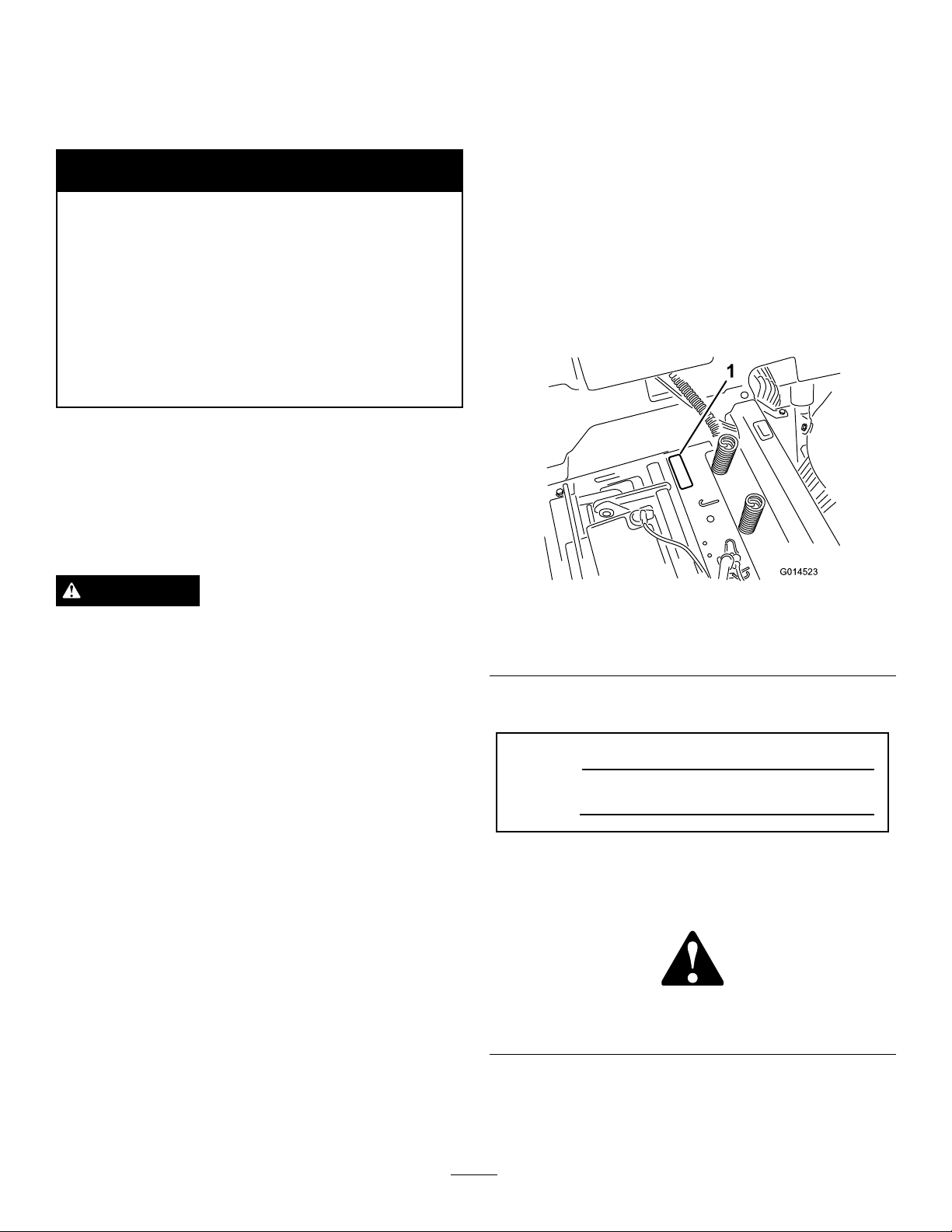
Wheneveryouneedservice,genuineToroparts,oradditional
information,contactanAuthorizedServiceDealerorToro
CustomerServiceandhavethemodelandserialnumbersof
yourproductready .Figure1identiesthelocationofthe
modelandserialnumbersontheproduct.Writethenumbers
inthespaceprovided.
ThissparkignitionsystemcomplieswithCanadianICES-002.
WARNING
Removingstandardoriginalequipmentpartsand
accessoriesmayalterthewarranty,traction,and
safetyofthemachine.FailuretouseoriginalToro
partscouldcauseseriousinjuryordeath.Making
unauthorizedchangestotheengine,fuelorventing
system,mayviolateEPAandCARBregulations.
Replaceallpartsincluding,butnotlimitedto,tires,
belts,blades,andfuelsystemcomponentswith
originalT oroparts.
Theenclosed
informationregardingtheUSEnvironmentalProtection
Agency(EPA)andtheCaliforniaEmissionControl
Regulationofemissionsystems,maintenance,and
warranty.Replacementsmaybeorderedthroughthe
enginemanufacturer.
Formodelswithstatedenginehorsepower,thegross
horsepoweroftheenginewaslaboratorytestedbytheengine
manufacturerinaccordancewithSAEJ1995andratedto
J2723.Asconguredtomeetsafety,emission,andoperating
requirements,theactualenginehorsepoweronthisclassof
lawnmowerwillbesignicantlylower.
Engine Owner's Man ual
issuppliedfor
Figure1
Undertheseat
1.Modelandserialnumberplate
Writetheproductmodelandserialnumbersinthespace
below:
ModelNo.
SerialNo.
Thismanualidentiespotentialhazardsandhassafety
messagesidentiedbythesafetyalertsymbol(Figure2),
whichsignalsahazardthatmaycauseseriousinjuryordeath
ifyoudonotfollowtherecommendedprecautions.
Figure2
1.Safetyalertsymbol.
Thismanualusestwootherwordstohighlightinformation.
Importantcallsattentiontospecialmechanicalinformation
andNoteemphasizesgeneralinformationworthyofspecial
attention.
©2012—TheToro®Company
8111LyndaleAvenueSouth
Bloomington,MN55420
Contactusatwww.T oro.com.
2
PrintedintheUSA.
AllRightsReserved
Page 3

Contents
Introduction..................................................................2
Safety...........................................................................4
SafeOperatingPractices...........................................4
ToroRidingMowerSafety........................................6
SlopeIndicator.......................................................7
SafetyandInstructionalDecals.................................8
ProductOverview.........................................................14
Controls...............................................................15
Operation....................................................................16
ThinkSafetyFirst...................................................16
BeforeStarting.......................................................18
StartingtheEngine.................................................19
OperatingtheBlades...............................................20
TestingtheSafetyInterlockSystem...........................20
StoppingtheEngine...............................................21
Driving.................................................................21
StoppingtheMachine.............................................22
AdjustingtheHeightofCut.....................................22
AdjustingtheAnti-ScalpRollers(For42inch
MowerDecks)....................................................23
AdjustingtheAnti-ScalpRollers(For50inch
MowerDecks)....................................................23
PositioningtheSeat................................................24
AdjustingtheMotionControlLevers........................24
PushingtheMachinebyHand..................................24
GrassDeector......................................................25
OperatingTips......................................................25
Maintenance.................................................................27
RecommendedMaintenanceSchedule(s)......................27
PremaintenanceProcedures........................................28
RaisingtheSeat......................................................28
Lubrication...............................................................28
GreasingtheBearings.............................................28
EngineMaintenance..................................................29
ServicingtheAirCleaner.........................................29
ServicingtheEngineOil..........................................29
ServicingtheSparkPlug..........................................31
CleaningtheCoolingSystem....................................32
FuelSystemMaintenance...........................................33
ServicingtheEmissionsFilter..................................33
ReplacingtheIn-lineFuelFilter................................33
ElectricalSystemMaintenance....................................34
ChargingtheBattery...............................................34
ServicingtheFuses.................................................35
DriveSystemMaintenance.........................................36
CheckingtheTirePressure......................................36
ReleasingtheElectricBrake.....................................36
MowerMaintenance...................................................37
ServicingtheCuttingBlades.....................................37
LevelingtheMowerDeck........................................39
RemovingtheMower..............................................42
MowerBeltMaintenance.........................................43
InstallingtheMower...............................................44
ReplacingtheGrassDeector..................................44
Cleaning...................................................................45
WashingtheUndersideoftheMower........................45
Storage........................................................................46
CleaningandStorage..............................................46
Troubleshooting...........................................................47
Schematics...................................................................49
3
Page 4

Safety
ThismachinemeetsorexceedstheB71.1-2003
specicationsoftheAmericanNationalStandards
Institute,ineffectatthetimeofproduction.However,
improperuseormaintenancebytheoperatororowner
canresultininjury.Toreducethepotentialforinjury,
complywiththesesafetyinstructionsandalwayspay
attentiontothesafetyalertsymbol,whichmeans
CAUTION,WARNING,orDANGER-"personalsafety
instruction."Failuretocomplywiththeinstructionmay
resultinpersonalinjuryordeath.
SafeOperatingPractices
Thisproductiscapableofamputatinghandsandfeetand
throwingobjects.Alwaysfollowallsafetyinstructionsto
avoidseriousinjuryordeath.
ThefollowinginstructionsarefromANSIstandard
B71.1-2003.AllthelanguagewithinthisANSIstandard
appliestothismachine;however,duetotheapplicationof
thestandardacrossmanydifferenttypesofproductssome
statementscanseemgeneralormisleading.Intheseinstances,
Torohasrenedthestatementtoconveythemeaningofthe
standardwhilebettermatchingtheproductthisOperator's
Manualpertains.Safetyinformationinadditiontothe
instructionsfoundintheANSIstandardbelowcanbefound
inToroRidingMowerSafetyattheendofthissection.
GeneralOperation
•Read,understand,andfollowallinstructionsinthe
operator'smanualandonthemachinebeforestarting.
•Donotplacehandsorfeetnearrotatingpartsorunder
themachine.Keepclearofthedischargeopeningatall
times.
•Allowonlyresponsibleadultswhoarefamiliarwiththe
instructionstooperatethemachine.
•Cleartheareaofobjectssuchasrocks,toys,wire,etc.,
whichcouldbepickedupandthrownbytheblade.
•Besuretheareaisclearofotherpeoplebeforemowing.
Stopthemachineifanyoneentersthearea.
•Nevercarrypassengers.
•Donotmowinreverseunlessabsolutelynecessary.
Alwayslookdownandbehindbeforeandwhilebacking
up.
•Beawareofthemowerdischargedirectionanddonot
pointitatanyone.Avoiddischargingmaterialagainsta
wallorobstruction.Materialmayricochetbacktoward
theoperator.Stoptheblade(s)whencrossinggravel
surfaces.
•Donotoperatethemachinewithoutdeector,discharge
coverorentiregrasscollectionsysteminplaceand
working.
•Bealert,slowdownandusecautionwhenmakingturns.
Lookbehindandtothesidebeforechangingdirections.
•Neverleavearunningmachineunattended.Alwaysturn
offblades,setparkingbrake,stopengine,andremovekey
beforedismounting.
•Turnoffbladeswhennotmowing.Stoptheengine,wait
forallpartstocometoacompletestopandremovethe
keybeforecleaningthemachine,removingthegrass
catcheroruncloggingthedischargechute.
•Operatethemachineonlyindaylightorgoodarticial
light.
•Donotoperatethemachinewhileundertheinuence
ofalcoholordrugs.
•Watchfortrafcwhenoperatingnearorcrossing
roadways.
•Useextracarewhenloadingorunloadingthemachine
intoatrailerortruck.
•Alwaysweareyeprotectionwhenoperatingthemower.
•Dataindicatesthatoperators,age60yearsandabove,are
involvedinalargepercentageofridingmower-related
injuries.Operatorsshouldevaluatetheirabilitytooperate
theridingmowersafelyenoughtoprotectthemselvesand
othersfromseriousinjury.
•Alwaysfollowtherecommendationsforanyapplication
ofcounterweights.
•Lightningcancausesevereinjuryordeath.Iflightning
isseenorthunderisheardinthearea,donotoperate
themachine;seekshelter.
SlopeOperation
Slopesareamajorfactorrelatedtolossofcontroland
tip-overaccidents,whichcanresultinsevereinjuryordeath.
Operationonallslopesrequiresextracaution.Ifyoucannot
backuptheslopeorifyoufeeluneasyonit,donotmowit.
•Donotmowslopesgreaterthan15degrees.
•Watchforditches,holes,rocks,dips,andrisesthatchange
theoperatingangle,asroughterraincouldoverturnthe
machine.
•Choosealowgroundspeedsoyouwillnothavetostop
whileoperatingonaslope.
•Donotmowslopeswhengrassiswet.Slippery
conditionsreducetractionandcouldcauseslidingand
lossofcontrol.
•Alwayskeepthedrivewheelsengagedwhengoingdown
slopes.
•Reducespeedanduseextremecautiononslopes.
•Donotmakesuddenturnsorrapidspeedchanges.
•Removeormarkobstaclessuchasrocks,treelimbs,etc.
fromthemowingarea.Tallgrasscanhideobstacles.
•Avoidsuddenstartswhenmowinguphillbecausethe
mowermaytipbackwards.
4
Page 5

•Beawarethatlossoftractionmayoccurgoingdownhill.
Weighttransfertothefrontwheelsmaycausedrive
wheelstoslipandcauselossofbrakingandsteering.
•Alwaysavoidsuddenstartingorstoppingonaslope.If
tireslosetraction,stopthemachine,disengagetheblades
andproceedslowlyofftheslope.
•Useextremecarewithgrasscatchersorotherattachments.
Thesecanchangethestabilityofthemachineandcause
lossofcontrol.
•Donottrytostabilizethemachinebyputtingyourfoot
ontheground.
•Donotmowneardrop-offs,ditches,steepbanksor
water.Wheelsdroppingoveredgescancauserollovers,
whichmayresultinseriousinjury,deathordrowning.
•Useawalkbehindmowerand/orahandtrimmernear
drop-offs,ditches,steepbanksorwater.
Children
Tragicaccidentscanoccuriftheoperatorisnotalerttothe
presenceofchildren.Childrenareoftenattractedtothe
machineandthemowingactivity.Neverassumethatchildren
willremainwhereyoulastsawthem.
•Keepchildrenoutofthemowingareaandunderthe
watchfulcareofanotherresponsibleadult,notthe
operator.
•Bealertandturnthemachineoffifchildrenenterthe
area.
•Beforeandwhilebackingorchangingdirection,look
behind,down,andside-to-sideforsmallchildren.
•Nevercarrychildren,evenwiththebladesoff.Theymay
falloffandbeseriouslyinjuredorinterferewithsafe
machineoperation.
•Childrenwhohavebeengivenridesinthepastmay
suddenlyappearinthemowingareaforanotherrideand
berunoverorbackedoverbythemower.
•Neverallowchildrentooperatethemachine.
•Useextracarewhenapproachingblindcorners,shrubs,
trees,theendofafenceorotherobjectsthatmayobscure
vision.
•Onslopes,theweightofthetowedequipmentmaycause
lossoftractionandlossofcontrol.
•Travelslowlyandallowextradistancetostop.
Service
SafeHandlingofGasoline:
Toavoidpersonalinjuryorpropertydamage,useextracare
whenhandlinggasolineandotherfuels.Theyareammable
andthevaporsareexplosive.
•Extinguishallcigarettes,cigars,pipesandothersources
ofignition.
•Useonlyanapprovedcontainer.
•Neverremovethegascaporaddfuelwhentheengineis
running.Allowtheenginetocoolbeforerefueling.
•Neverrefuelthemachineindoors.
•Neverstorethemachineorfuelcontainerinsidewhere
thereisanopename,suchasnearawaterheateror
furnace.
•Neverllcontainersinsideavehicleoronatruckor
trailerwithaplasticliner.Alwaysplacecontainersonthe
groundawayfromyourvehiclebeforelling.
•Removegas-poweredequipmentfromthetruckortrailer
andrefuelitontheground.Ifthisisnotpossible,then
refuelsuchequipmentwithaportablecontainer,rather
thanfromagasolinedispensernozzle.
•Keepthenozzleincontactwiththerimofthefueltank
orcontaineropeningatalltimesuntilthefuelingis
complete.Donotuseanozzlelock-opendevice.
•Iffuelisspilledonclothing,changeclothingimmediately.
•Neveroverllthefueltank.Replacegascapandtighten
securely.
GeneralService:
•Neveroperateamachineinsideaclosedarea.Engine
exhaustcontainscarbonmonoxide,whichisanodorless,
deadlypoisonthatcankillyou.
•Keepnutsandboltstight,especiallythebladeattachment
bolts.Keepequipmentingoodcondition.
Towing
Ahitchkitisavailableforthismachineandcanbeobtained
bycontactinganAuthorizedToroDealer.Donottow
withoutrstinstallingthismanufacturerapprovedhitch.The
followingguidelinesapplywhentowingwiththeapproved
hitchkitinstalled.
•Towonlywithamachinethathasahitchdesignedfor
towing.Donotattachtowedequipmentexceptatthe
hitchpoint.
•Followthemanufacturer'srecommendationforweight
limitsfortowedequipmentandtowingonslopes.
•Neverallowchildrenorothersinorontowedequipment.
•Nevertamperwithsafetydevices.Checktheirproper
operationregularly.
•Keepthemachinefreeofgrass,leaves,orotherdebris
build-up.Cleanupoilorfuelspillagefuelsoakeddebris.
Allowthemachinetocoolbeforestoring.
•Stopandinspecttheequipmentifyoustrikeanobject.
Repair,ifnecessary,beforerestarting.
•Nevermakeanyadjustmentsorrepairswiththeengine
running.
•Grasscatchercomponentsaresubjecttowear,damage
anddeterioration,whichcouldexposemovingpartsor
allowobjectstobethrown.Frequentlycheckcomponents
5
Page 6

andreplacewithmanufacturers'recommendedparts,
whennecessary.
•Mowerbladesaresharpandcancut.Wraptheblade(s)or
weargloves,anduseextracautionwhenservicingthem.
•Checkforproperbrakeoperationfrequently.Adjustand
serviceasrequired.
•Maintainorreplacesafetyandinstructiondecalsas
necessary.
•UseonlygenuineTororeplacementpartstoensurethat
originalstandardsaremaintained.
ToroRidingMowerSafety
ThefollowinglistcontainssafetyinformationspecictoToro
productsorothersafetyinformationthatyoumustknowthat
maynotbeincludedintheANSIstandards.
•Stoptheengine,movethemotioncontrolleverstoneutral
andoutwardtotheparkposition,disengagetheblade
controlswitch,removekeybeforeanddisconnectspark
plugwire(s)performinganyservice,repairs,maintenance
oradjustments.
•Keephands,feet,hair,andlooseclothingawayfrom
attachmentdischargearea,undersideofmowerandany
movingpartswhileengineisrunning.
•Donottouchequipmentorattachmentpartswhichmay
behotfromoperation.Allowtocoolbeforeattempting
tomaintain,adjustorservice.
•Batteryacidispoisonousandcancauseburns.Avoid
contactwithskin,eyes,andclothing.Protectyourface,
eyes,andclothingwhenworkingwithabattery.
•Batterygasescanexplode.Keepcigarettes,sparksand
amesawayfrombattery.
•UseonlyToroapprovedattachments.Warrantymaybe
voidedifusedwithunapprovedattachments.
•Ifloadingthemachineontoatrailerortruck,useasingle,
full-widthramponly.Therampangleshouldnotexceed
15degrees.
6
Page 7
SlopeIndicator
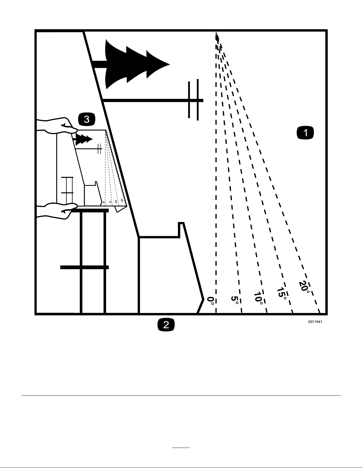
G011841
Figure3
Thispagemaybecopiedforpersonaluse.
1.Themaximumslopeyoucansafelyoperatethemachineonis15degrees.Usetheslopecharttodeterminethedegreeofslope
ofhillsbeforeoperating.Donotoperatethismachineonaslopegreaterthan15degrees.Foldalongtheappropriateline
tomatchtherecommendedslope.
2.Alignthisedgewithaverticalsurface,atree,building,fencepole,etc.
3.Exampleofhowtocompareslopewithfoldededge.
7
Page 8
SafetyandInstructional
Decals
Safetydecalsandinstructionsareeasilyvisibletotheoperatorandarelocatednearanyareaofpotential
danger.Replaceanydecalthatisdamagedorlost.
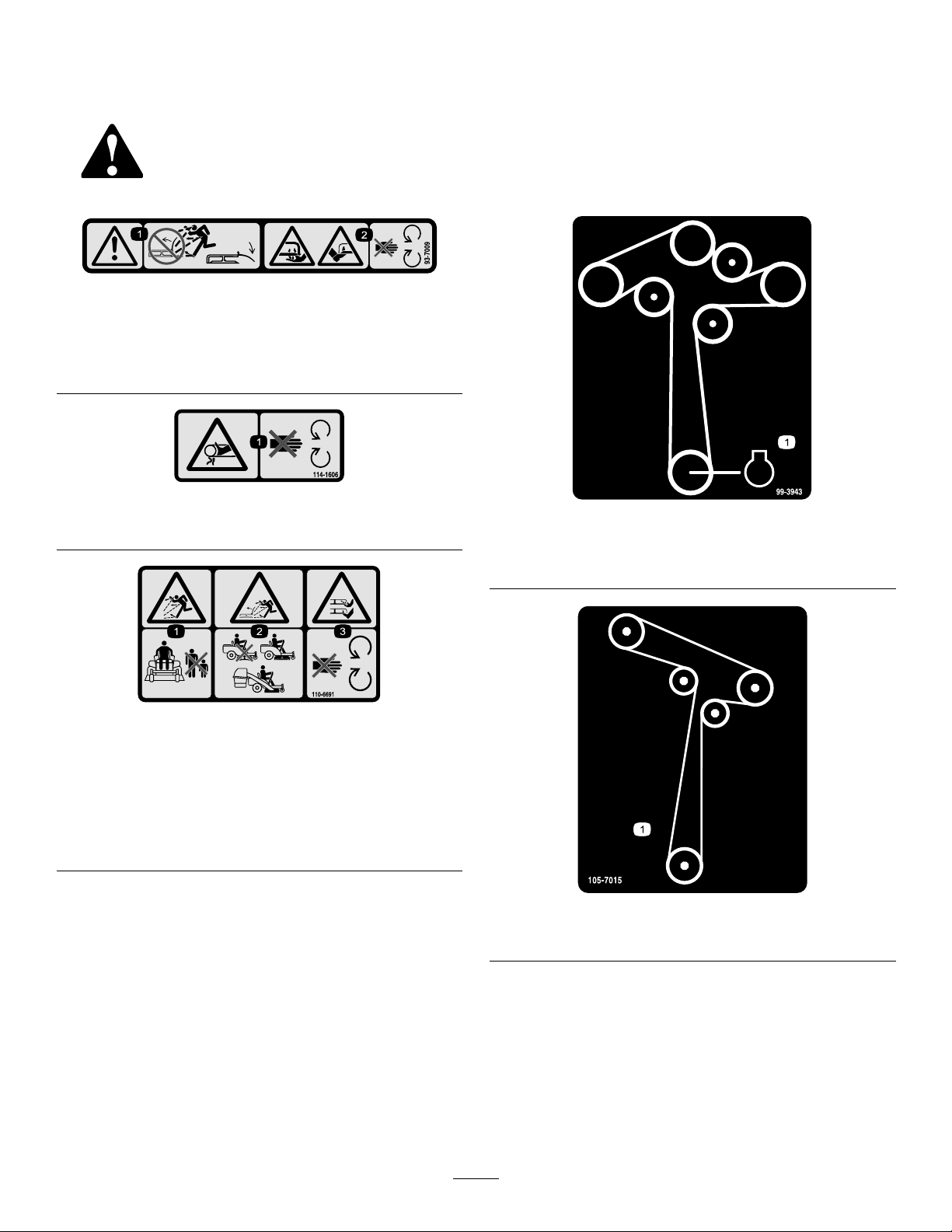
93-7009
1.Warning—don'toperatethemowerwiththedeectorupor
removed;keepthedeectorinplace.
2.Cutting/dismembermenthazardofhandorfoot,mower
blade—stayawayfrommovingparts.
114-1606
1.Entanglementhazard,belt—keepallguardsinplace.
99-3943
ForModelswith50InchDecks
110-6691
1.Thrownobjecthazard—keepbystandersasafedistance
fromthemachine.
2.Thrownobjecthazard,mower—donotoperatewithoutthe
deector,dischargecover,orgrasscollectionsystemin
place.
3.Cutting/dismembermentofhandorfoot—stayawayfrom
movingparts.
1.Engine
105-7015
ForModelswith42InchDecks
8
Page 9
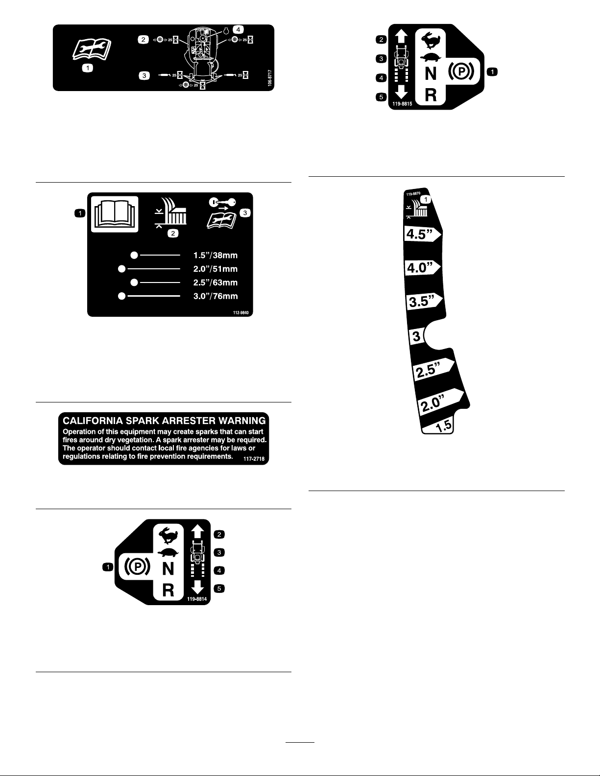
106-8717
1.Readtheinstructionsbeforeservicingorperforming
maintenance.
2.Checktirepressureevery25operatinghours.
3.Greaseevery25operatinghours.
4.Engine
112-9840
1.ReadtheOperator's
Manual.
2.Heightofcut
3.Removetheignitionkey
119-8815
1.Parkingposition4.Neutral
2.Fast5.Reverse
3.Slow
andreadtheinstructions
beforeservicingor
performingmaintenance.
117–2718
Model74625only
119-8814
1.Parkingposition4.Neutral
2.Fast5.Reverse
3.Slow
119-8870
50InchModel
1.Height-of-cut
9
Page 10
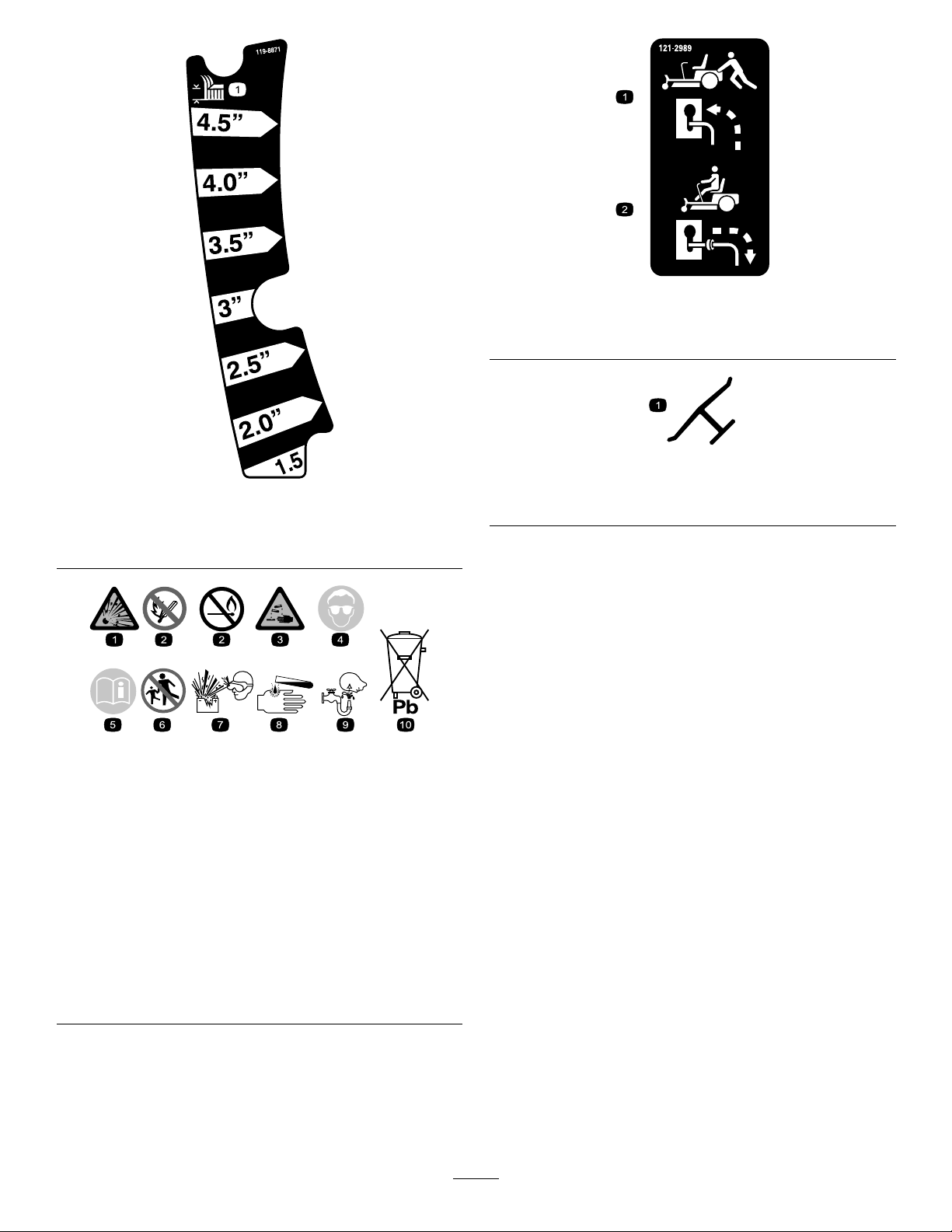
121-2989
119-8871
Certainmodelsonly
1.Height-of-cut
BatterySymbols
Someorallofthesesymbolsareonyourbattery
1.Bypassleverpositionfor
pushingthemachine
2.Bypassleverpositionfor
operatingthemachine
Manufacturer'sMark
1.Indicatesthebladeisidentiedasapartfromtheoriginal
machinemanufacturer.
1.Explosionhazard
2.Nore,opename,or
smoking.
3.Causticliquid/chemical
burnhazard
4.Weareyeprotection9.Flusheyesimmediately
5.ReadtheOperator's
Manual.
6.Keepbystandersasafe
7.Weareyeprotection;
8.Batteryacidcancause
10.Containslead;donot
distancefromthebattery .
explosivegasescan
causeblindnessandother
injuries
blindnessorsevereburns.
withwaterandgetmedical
helpfast.
discard.
10
Page 11
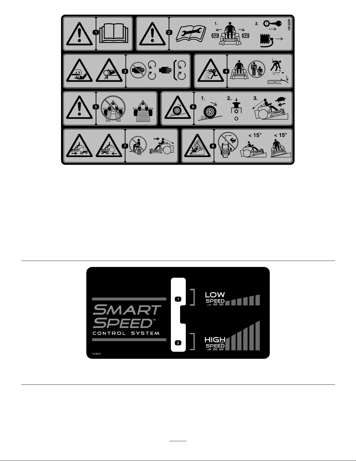
120-2239
1.Warning—readtheOperator'sManual.5.Warning—donotusesplitramps,useafullrampswhen
2.Warning—readtheinstructionsbeforeservicingorperforming
maintenance;movethemotioncontrolleverstothepark
(brake)position,removetheignitionkeyanddisconnectthe
sparkplugwire.
3.Cutting/dismembermenthazard,mowerblade;entanglement
hazard,belt—stayawayfrommovingparts,keepallguards
andshieldsinplace.
4.Thrownobjecthazard—keepbystandersasafedistancefrom
themachine,pickupdebrisbeforeoperating,keepdeector
inplace.
transportingmachine.
6.Lossoftraction/controlhazard,slopes—lossoftraction/control
onaslope,disengagethebladecontrolswitch(PTO),
proceedofftheslopeslowly .
7.Crushing/dismembermenthazardofbystanders,reversing;
crushing/dismembermenthazardofbystanders—donotcarry
passengers,lookbehindanddownwhenreversing.
8.Tippinghazard—donotmowslopesgreaterthan15degrees,
avoidsuddenandsharpturnswhileonslopes.
119-8874
1.Lowspeed2.Highspeed
11
Page 12
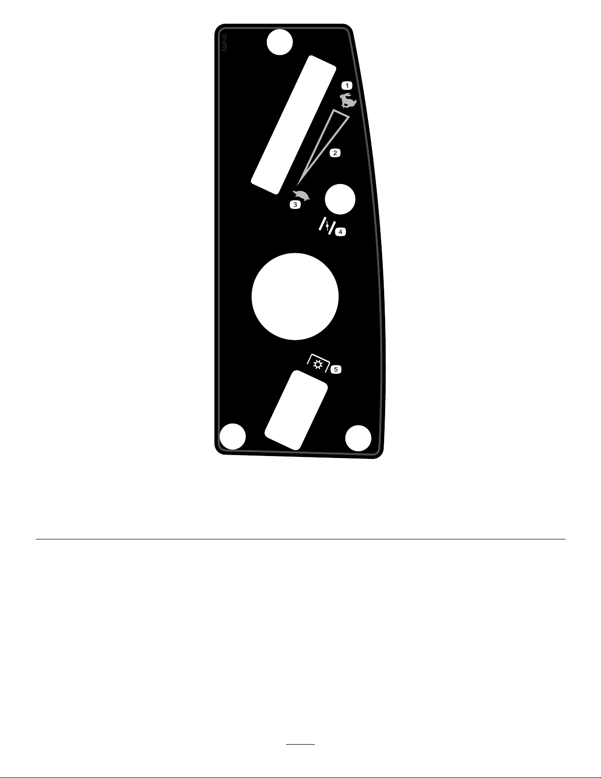
121-0772
Models74625and74626only
1.Fast
2.Continuousvariablesetting5.Powertake-off(PTO),Bladecontrolswitch
3.Slow
4.Choke
12
Page 13
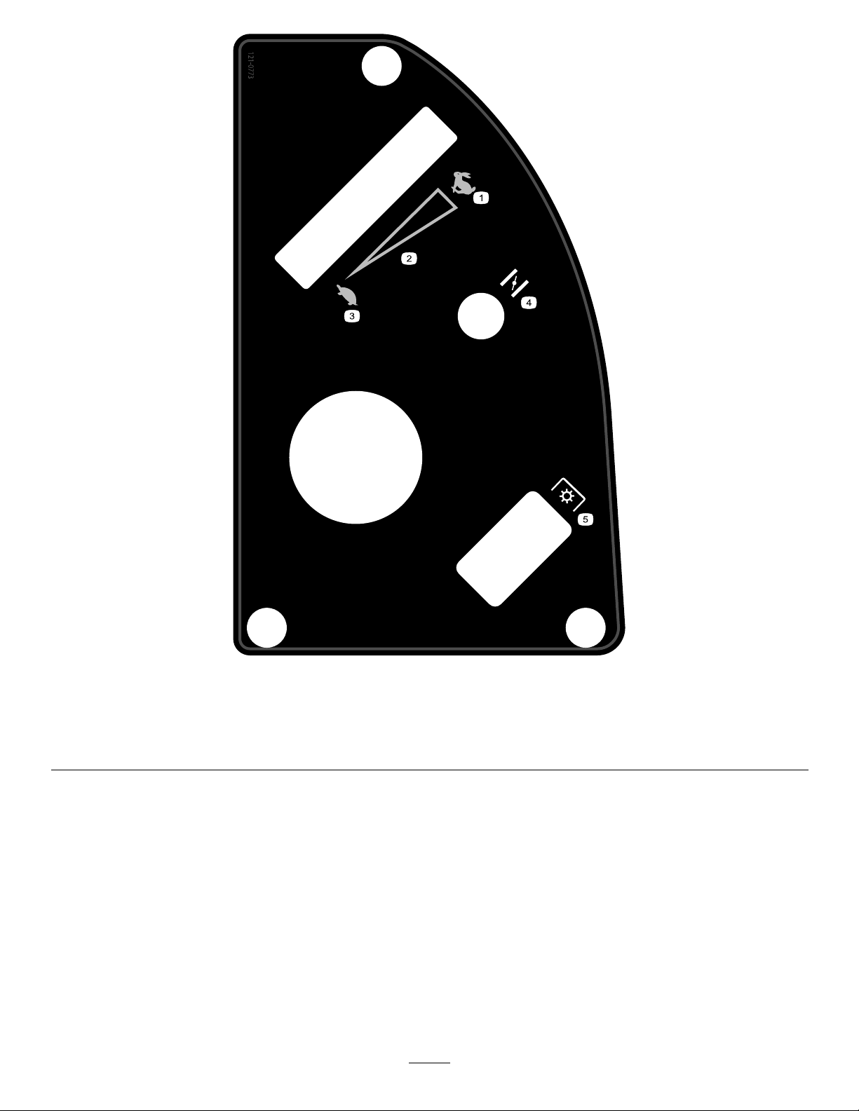
121-0773
Models74631and74632only
1.Fast
2.Continuousvariablesetting5.Powertake-off(PTO),Bladecontrolswitch
3.Slow
4.Choke
13
Page 14
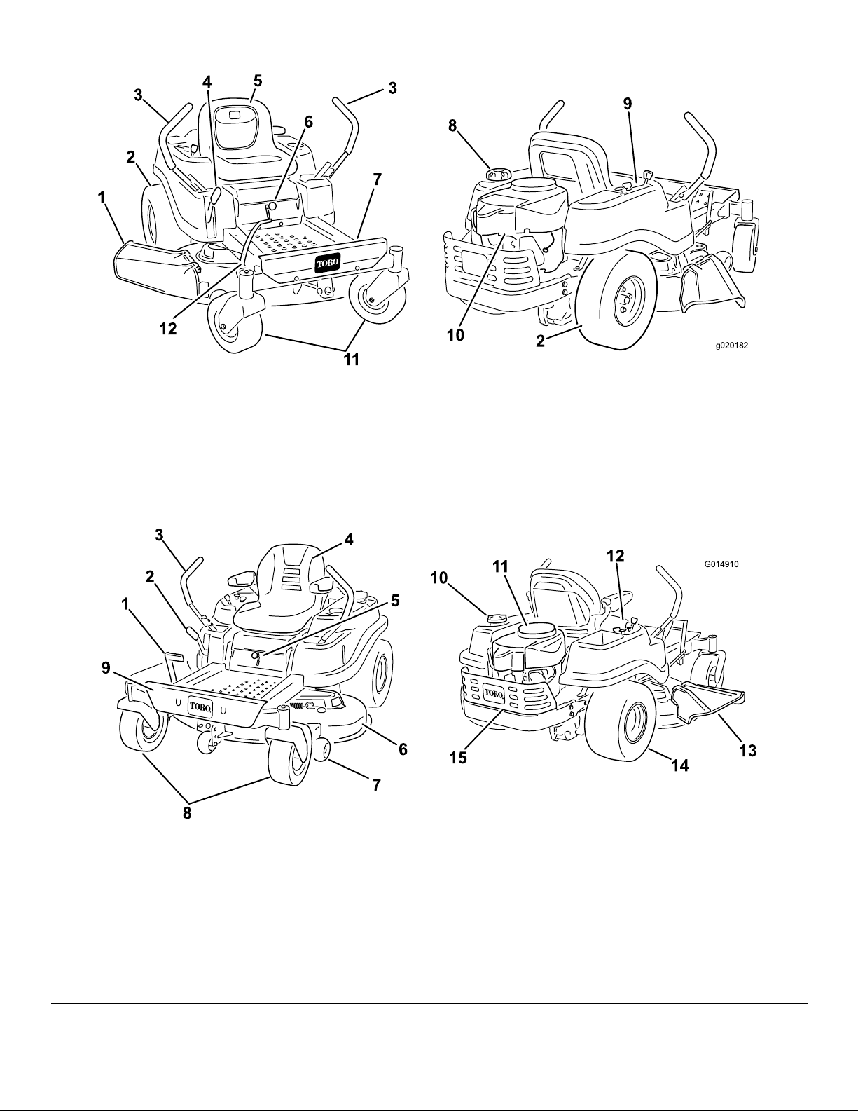
ProductOverview
g020182
12
G014910
1
2
3
4
5
6
7
8
9
10
11
12
13
14
15
Figure4
Models74625and74626
1.Deector4.Heightofcutlever
2.Reardrivewheel
3.Motioncontrollevers
1.Footassistlever(certain
modelsonly)
2.Heightofcutlever
3.Motioncontrollevers7.Anti-scalproller11.Engine
4.Operatorseat(armrests
optional)
5.Operatorseat
6.SmartSpeed™lever9.Controlpanel12.Footassistlever(certain
5.SmartSpeed™lever
Models74631,and74632
6.Mowerdeck
8.Frontcasterwheel
7.Footrest
8.Fueltankcap11.Frontcasterwheel
Figure5
9.Footrest
10.Gastankcap
12.Controlpanel
10.Engineguard(certain
modelsonly)
modelsonly)
13.Deector
14.Reardrivewheel
15.Engineguard(certain
modelsonly)
14
Page 15
Controls
G014475
1
G014521
1
BecomefamiliarwithallofthecontrolsinFigure4,Figure5,
andFigure6beforeyoustarttheengineandoperatethe
machine.
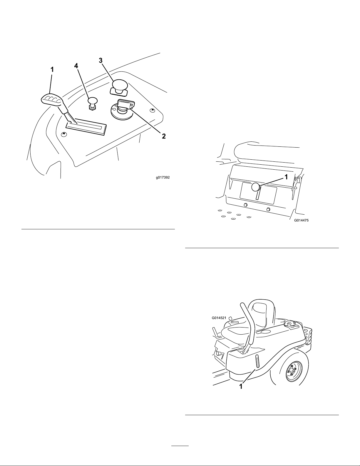
Figure6
ControlPanel
MotionControlLeversandPark
Position
Themotioncontrolleversarespeedsensitivecontrolsof
independentwheelmotors.Movingaleverforwardor
backwardturnsthewheelonthesamesideforwardorin
reverse;wheelspeedisproportionaltotheamountthelever
ismoved.Movethecontrolleversoutwardfromthecenter
totheparkpositionandexitthemachine(Figure18).Always
positionthemotioncontrolleversintotheparkposition
whenyoustopthemachineorleaveitunattended.
SmartSpeed™ControlSystemLever
TheSmartSpeed™ControlSystemlever,locatedbelowthe
operatingposition,givestheoperatorachoicetodrivethe
machineattwospeedranges,highandlow(Figure7).
1.Throttle3.Bladecontrolswitch
2.Ignitionswitch
(powertake-off)
4.Choke
IgnitionSwitch
Theignitionswitchhasthreepositions,Off,RunandStart.
ThekeywillturntoStartandmovebacktoRunuponrelease.
TurningthekeytotheOffpositionwillstoptheengine;
however,alwaysremovethekeywhenleavingthemachine
topreventsomeonefromaccidentallystartingtheengine
(Figure6).
ThrottleControl
Thethrottlecontrolstheenginespeedandithasacontinuous
variablesettingfromSlowtoFast(Figure6).
ChokeControl
PullupontheChokecontroluntilitstopstochokethe
engine(Figure6).PushdownontheChokecontrolfor
normalengineoperation
Figure7
1.Smartspeedlever
FuelWindow
Thefuelwindowlocatedonthelefthandsideofthemachine
canbeusedtoverifythepresenceofgasolineinthetank
(Figure8).
BladeControlSwitch(PowerTake-Off)
Thebladecontrolswitch,representedbyapowertake-off
(PTO)symbol,engagesanddisengagespowertothemower
blades(Figure6).
Figure8
1.Fuelpresencewindow
15
Page 16
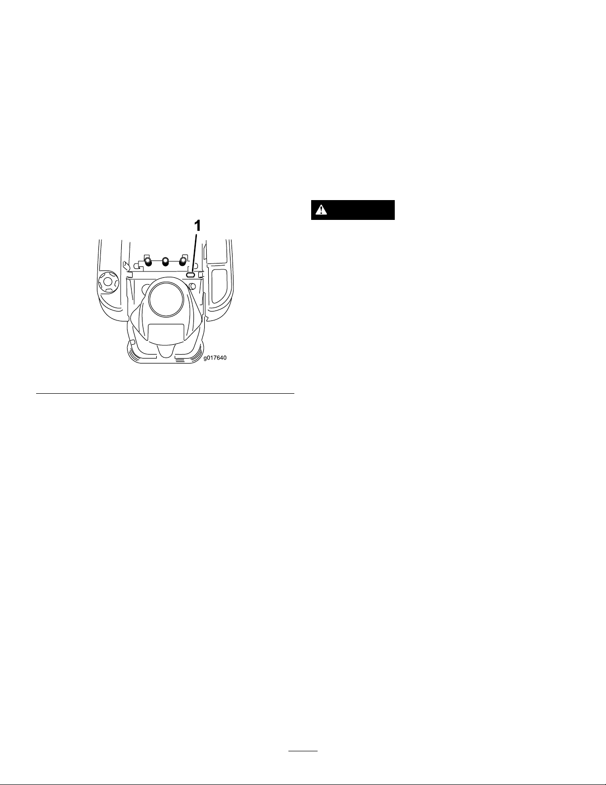
Height-of-CutLever
g017640
1
Theheightofcutleverallowstheoperatortolowerand
raisethedeckfromtheseatedposition.Whentheleveris
movedup,towardtheoperatorthedeckisraisedfromthe
groundandwhenmoveddown,awayfromtheoperatoritis
loweredtowardtheground.Onlyadjusttheheightofcut
whilemachineisnotmoving(Figure22).
Operation
Note:Determinetheleftandrightsidesofthemachine
fromthenormaloperatingposition.
ThinkSafetyFirst
HourMeter
Models74626and74632
Thehourmeterrecordsthenumberofhourswhenthe
operatorisintheseatandtheignitionswitchisintheON
position(Figure9).
Figure9
OperatingSafety
Pleasecarefullyreadallofthesafetyinstructionsanddecals
inthesafetysection.Knowingthisinformationcouldhelp
you,yourfamily,petsorbystandersavoidinjury.
DANGER
Mowingonwetgrassorsteepslopescancause
slidingandlossofcontrol.
Wheelsdroppingoveredgescancauserollovers,
whichmayresultinseriousinjury,deathor
drowning.
Alossoftractionisalossofsteeringcontrol.
Toavoidlossofcontrolandpossibilityofrollover:
•Donotmowneardrop-offsornearwater.
•Donotmowslopesgreaterthan15degrees.
•Reducespeedanduseextremecautionon
slopes.
•Whenmowingslopes,graduallyworkfrom
lowertohigherareasontheincline.
•Avoidsuddenturnsorrapidspeedchanges.
•Turnup,intoaninclinewhenchanging
directionsonslopes.Turningdowntheslope
reducestraction.
•Attachmentschangethehandlingcharacteristics
ofthemachine.Useextracautionwhenusing
attachmentswiththemachine.
16
Page 17

1.SafeZone-usethe
TimeCutterhere
2.Usewalkbehindmower
and/orhandtrimmernear
drop-offsandwater .
FuelSafety
DANGER
Figure10
3.Water
DANGER
Incertainconditionsduringfueling,static
electricitycanbereleasedcausingasparkwhich
canignitethegasolinevapors.Areorexplosion
fromgasolinecanburnyouandothersandcan
damageproperty.
•Alwaysplacegasolinecontainersontheground
awayfromyourvehiclebeforelling.
•Donotllgasolinecontainersinsideavehicleor
onatruckortrailerbedbecauseinteriorcarpets
orplastictruckbedlinersmayinsulatethe
containerandslowthelossofanystaticcharge.
•Whenpractical,removegas-poweredequipment
fromthetruckortrailerandrefueltheequipment
withitswheelsontheground.
•Ifthisisnotpossible,thenrefuelsuch
equipmentonatruckortrailerfromaportable
container,ratherthanfromagasolinedispenser
nozzle.
•Ifagasolinedispensernozzlemustbeused,
keepthenozzleincontactwiththerimofthe
fueltankorcontaineropeningatalltimesuntil
fuelingiscomplete.
Incertainconditions,gasolineisextremely
ammableandhighlyexplosive.Areorexplosion
fromgasolinecanburnyouandothersandcan
damageproperty.
•Fillthefueltankoutdoors,inanopenarea,
whentheengineiscold.Wipeupanygasoline
thatspills.
•Neverllthefueltankinsideanenclosedtrailer.
•Donotllthefueltankcompletelyfull.Add
gasolinetothefueltankuntilthefuelreaches
thebaseofthellerneck.Thisemptyspacein
thetankallowsgasolinetoexpand.
•Neversmokewhenhandlinggasoline,andstay
awayfromanopenameorwheregasoline
fumesmaybeignitedbyaspark.
•Storegasolineinanapprovedcontainerand
keepitoutofthereachofchildren.Neverbuy
morethana30-daysupplyofgasoline.
•Donotoperatewithoutentireexhaustsystemin
placeandinproperworkingcondition.
WARNING
Gasolineisharmfulorfatalifswallowed.Long-term
exposuretovaporscancauseseriousinjuryand
illness.
•Avoidprolongedbreathingofvapors.
•Keepfaceawayfromnozzleandgastankor
conditioneropening .
•Keepgasawayfromeyesandskin.
UnderstandingtheSafetyInterlock
System
WARNING
Ifsafetyinterlockswitchesaredisconnectedor
damagedthemachinecouldoperateunexpectedly
causingpersonalinjury.
•Donottamperwiththeinterlockswitches.
•Checktheoperationoftheinterlockswitches
dailyandreplaceanydamagedswitchesbefore
operatingthemachine.
Thesafetyinterlocksystemisdesignedtopreventtheengine
fromstartingunless:
•Thebladesaredisengaged.
•Themotioncontrolleversareintheparkposition.
17
Page 18

Thesafetyinterlocksystemalsoisdesignedtostoptheengine
G014474
1
2
3
4
5
6
G014895
1
2
3
4
wheneverthecontrolleversareoutoftheparkpositionand
yourisefromtheseat.
BeforeStarting
RecommendedFuel
•Forbestresults,useonlyclean,fresh,unleadedgasoline
withanoctaneratingof87orhigher((R+M)/2rating
method).
•Oxygenatedfuelwithupto10%ethanolor15%MTBE
byvolumeisacceptable.
•DoNotuseethanolblendsofgasoline(suchasE15
orE85)withmorethan10%ethanolbyvolume.
Performanceproblemsand/orenginedamagemayresult
whichmaynotbecoveredunderwarranty.
•DoNotusegasolinecontainingmethanol.
•DoNotstorefueleitherinthefueltankorfuelcontainers
overthewinterunlessafuelstabilizerisused.
•DoNotaddoiltogasoline.
2.Slowlyaddregular,unleadedgasolineuntilthefuel
reachesthebaseofthellerneck(Figure11).
Figure11
1.Fueltankcap
2.Fillopening5.Fuelwindow
3.Fillerneck
4.Baseofllerneck,DO
NOTFILLP ASTHERE
UsingStabilizer/Conditioner
Useafuelstabilizer/conditionerinthemachinetoprovide
thefollowingbenets:
•Keepsgasolinefreshduringstorageof90daysorless.
Forlongerstorageitisrecommendedthatthefueltank
bedrained.
•Cleanstheenginewhileitruns.
•Eliminatesgum-likevarnishbuildupinthefuelsystem,
whichcauseshardstarting.
Addthecorrectamountofgasstabilizer/conditionertothe
gas.
Note:Afuelstabilizer/conditionerismosteffectivewhen
mixedwithfreshgasoline.T ominimizethechanceofvarnish
depositsinthefuelsystem,usefuelstabilizeratalltimes.
FillingtheFuelTank
Makesuretheengineisshutoffandthemotioncontrolsare
intheparkposition.Tankmaximumcapacityis2.9gallons.
Important:DoNotoverllfueltank.Fillthefueltank
tothebottomofthellerneck.Theemptyspaceinthe
tankallowsthefueltoexpand.Overllingmayresult
infuelleakageordamagetotheengineoremissions
system.
1.Cleanaroundthefueltankcapandremovethecap.
Note:Youcanusethefuelwindowtoverifythe
presenceofgasolinebeforellingthetank(
Figure11).
Figure12
1.Fillopening3.Fuel
2.Baseofllerneck,DO
NOTFILLP ASTHERE
Important:DoNotoverllfueltank.Fillthe
fueltanktothebottomofthellerneck.The
emptyspaceinthetankallowsthefueltoexpand.
Overllingmayresultinfuelleakageordamage
totheengine.
3.Installthefueltankcapsecurelyandtightenuntilit
“clicks”.Wipeupanygasolinethatmayhavespilled.
4.Emptyspaceforfuel
expansion.
CheckingtheEngineOilLevel
Beforeyoustarttheengineandusethemachine,checktheoil
levelintheenginecrankcase;refertoCheckingtheOilLevel
intheEngineMaintenancesection.
18
Page 19

StartingtheEngine
1.Sitdownontheseatandmovethemotioncontrols
outwardtotheparkposition.
2.Disengagethebladesbymovingthebladecontrol
switchtoOff(Figure13)
Figure14
Figure13
1.Controlpanel2.Bladecontrolswitch—Off
position
3.PullupontheChokecontrolbeforestartingacold
engine(Figure14).
Note:Awarmorhotenginemaynotrequirechoking.
1.Controlpanel4.Continuousvariable
2.Throttle
3.Fast
setting
5.Slow
6.Chokecontrol
4.TurntheignitionkeytoStarttoenergizethestarter.
Whentheenginestarts,releasethekey(Figure15).
Important:Donotengagethestarterformore
than10secondsatatime.Iftheenginefailsto
start,allowa60secondcool-downperiodbetween
attempts.Failuretofollowtheseinstructionscan
damagethestartermotor.
19
Page 20

Figure16
Figure15
1.Controlpanel
2.Ignitionkey—runposition
3.Ignitionkey—startposition
4.Off
5.Aftertheenginestarts,pushdownontheChoke
control(
upontheChokecontrolandlettheenginerunfora
fewseconds.ThenpushdownontheChokecontrol.
Repeatthisasrequired.
Figure15).Iftheenginestallsorhesitates,pull
5.Run
6.Start
7.Chokecontrol
OperatingtheBlades
Thebladecontrolswitch,representedbyapowertake-off
(PTO)symbol,engagesanddisengagespowertothemower
blades.Thisswitchcontrolspowertoanyattachmentsthat
drawpowerfromtheengine,includingthemowerdeckand
cuttingblades.
EngagingtheBlades
1.Controlpanel2.Bladecontrolswitch—On
position
DisengagingtheBlades
PushdownonthebladecontrolswitchtomoveittotheOff
positionanddisengagetheblades(Figure17).
Important:Donotengagethebladeswhenparkedin
tallgrass.Beltorclutchdamagecanoccur.
1.Releasepressureonthemotioncontrolleversand
placethemachineinneutral.
2.MovethethrottletotheFastposition.
Note:Alwaysengagethebladeswiththethrottlein
theFastposition.
3.Pulluponthebladecontrolswitchtomoveittothe
Onpositionandengagetheblades(
Figure16).
Figure17
1.Controlpanel2.Bladecontrolswitch—Off
TestingtheSafetyInterlock System
Testthesafetyinterlocksystembeforeyouusethemachine
eachtime.Ifthesafetysystemdoesnotoperateasdescribed
below,haveanAuthorizedServiceDealerrepairthesafety
systemimmediately.
20
Page 21

1.Whilesittingontheseat,withthecontrolleversinpark
G014475
1
position,andmovethebladecontrolswitchtoOn.Try
startingtheengine;theengineshouldnotcrank.
2.Whilesittingontheseat,movethebladecontrol
switchtoOff.Moveeithermotioncontrollevertothe
center,unlockedposition.Trystartingtheengine;the
engineshouldnotcrank.Repeatwiththeothermotion
controllever.
3.Whilesittingontheseat,movethebladecontrolswitch
toOff,andlockthemotioncontrolleversinthepark
position.Starttheengine.Whiletheengineisrunning,
engagethebladecontrolswitch,andriseslightlyfrom
theseat;theengineshouldstop.
4.Whilesittingontheseat,movethebladecontrolswitch
toOff,andlockthemotioncontrolleversinthepark
position.Starttheengine.Whiletheengineisrunning,
movethemotioncontrolleverstothecenter,unlocked
position,engagethebladecontrolswitch,andrise
slightlyfromtheseat;theengineshouldstop.
StoppingtheEngine
1.Disengagethebladesbymovingthebladecontrol
switchtoOff(Figure17).
Figure18
2.MovethethrottlelevertobetweentheFastposition
(Figure14).
3.TurntheignitionkeytoOff(Figure15)andremove
thekey.
Driving
Drivingthemachinebenetsfromanunderstandingof
whatzeroturnradiusmowermeans.Thedrivewheelsturn
independently,poweredbyhydraulicmotorsoneachaxle;
henceonesidecanturninreversewhiletheotherturns
forwardcausingthemachinetospinratherthanturn.This
vastlyimprovesthemachinemaneuverabilitybutmayrequire
someadjustmentiftheoperatorisunfamiliar.
WARNING
Themachinecanspinveryrapidly .Theoperator
maylosecontrolofthemachineandcausepersonal
injuryordamagetothemachine.
•Usecautionwhenmakingturns.
•Slowthemachinedownbeforemakingsharp
turns.
1.Park(brake)position
2.Centerunlockposition
3.Forward
4.Backward
UsingtheSmartSpeed™Control
System
TheSmartSpeed™ControlSystemlever,locatedbelowthe
operatingposition(Figure19),givestheoperatorachoiceto
drivethemachineattwogroundspeedranges,highandlow .
Figure19
1.Smartspeedlever
Thethrottlecontrolregulatestheenginespeedasmeasured
inrpm(revolutionsperminute).Placingthethrottlecontrol
intheFastpositioncanbebestforperformance.Formost
applications,operatinginthefullthrottlepositionisdesirable.
Tochangespeeds:
1.Movethemotioncontrolleverstoneutralandoutward
totheparkposition;disengagethebladecontrolswitch.
21
Page 22

WARNING
G008952
G008953
Removingyourhandsfromthemotioncontrol
leverswhilethemachineisinmotioncan
resultinalossofcontrolcausingharmtoyou
orbystanders.
Alwaysstopthemachineandmovethemotion
controlleverstotheparkpositionbefore
adjustingtheSmartSpeed™ControlSystem.
2.Adjustthelevertothedesiredposition.
Forward
1.Movetheleverstothecenter,unlockedposition.
2.Togoforward,slowlypushthemotioncontrollevers
forward(Figure18).
Figure20
Figure21
Togostraight,applyequalpressuretobothmotion
controllevers(Figure21).
Toturn,releasethepressureonthemotioncontrol
levertowardthedirectionyouwanttoturn.
Tostop,pushthemotioncontrolleverstoneutral.
StoppingtheMachine
Tostopthemachine,movethemotioncontrolleversto
neutralandoutwardtotheparkposition,disengagetheblade
controlswitch,ensurethethrottleisinthefastposition,and
turntheignitionkeytoOff.Remembertoremovethekey
fromtheignitionswitch.
WARNING
Childrenorbystandersmaybeinjuredifthey
moveorattempttooperatethemowerwhileitis
unattended.
Togostraight,applyequalpressuretobothmotion
controllevers(Figure18).
Toturn,releasepressureonthemotioncontrollever
towardthedirectionyouwanttoturn(Figure18).
Thefartheryoumovethemotioncontrolleversin
eitherdirection,thefasterthemachinewillmovein
thatdirection.
Tostop,pullthemotioncontrolleverstoneutral.
Backward
1.Movetheleverstothecenter,unlockedposition.
2.Togobackward,lookbehindyouanddownas
youslowlypullthemotioncontrolleversrearward
(Figure21).
Alwaysremovetheignitionkeyandmovethe
motioncontrolleversoutwardtotheparkposition
whenleavingthemachineunattended,evenifjust
forafewminutes.
AdjustingtheHeightofCut
Height-of-cutiscontrolledbytheleverlocatedtotherightof
theoperatingposition(Figure22).
22
Page 23

G014476
1
2
3
g019929
1
2
3
4
5
Figure23
G010233
1
2
3
4
Figure22
1.Height-of-cutlever3.4.5inch(1 15mm),
Transportposition
2.Height-of-cutpositions
1.Pullupandinwardonthelevertomoveittothe
desiredcuttingposition.
2.Onceatthedesiredcuttingposition,slowlylowerthe
leveruntilitengagestheposition.
Thetransportpositionisthehighestheight-of-cutpositionor
cuttingheight4.5inch[115mm](Figure22).
AdjustingtheAnti-Scalp Rollers(For42inchMower Decks)
Wheneveryouchangetheheight-of-cut,itisrecommended
toadjusttheheightoftheanti-scalprollers.
Note:Adjusttheanti-scalprollerssotherollersdonottouch
thegroundinnormal,atmowingareas.
1.Anti-scalproller4.Upperhole—themower
2.Lowerhole—themower
deckinthe76mm(3inch)
andaboveheight-of-cut
positions
3.FlangeNut
deckinthe63mm
(2-1/2inch)andbelow
height-of-cutpositions
5.Bolt
AdjustingtheAnti-Scalp Rollers(For50inchMower Decks)
Wheneveryouchangetheheight-of-cut,itisrecommended
toadjusttheheightoftheanti-scalprollers.
Note:Adjusttheanti-scalprollerssotherollersdonottouch
thegroundinnormal,atmowingareas.
1.Disengagethebladecontrolswitch(PTO),movethe
motioncontrolleverstotheneutrallockpositionand
settheparkingbrake.
2.Stoptheengine,removethekey ,andwaitforallmoving
partstostopbeforeleavingtheoperatingposition.
3.Adjusttheanti-scalprollersasshowninFigure24to
matchtheclosestheight-of-cutposition.
1.Disengagethebladecontrolswitch(PTO),movethe
motioncontrolleverstotheneutrallockpositionand
settheparkingbrake.
2.Stoptheengine,removethekey ,andwaitforallmoving
partstostopbeforeleavingtheoperatingposition.
3.Adjusttheanti-scalprollerstooneofthefollowing
positions:
•Upperhole—usethispositionwiththemowerdeck
inthe63mm(2-1/2inch)andbelowheight-of-cut
positions(
•Lowerhole—usethispositionwiththemower
deckinthe76mm(3inch)andaboveheight-of-cut
positions(Figure23).
Figure23).
Figure24
1.Anti-scalproller3.FlangeNut
2.Bolt4.Holespacing
23
Page 24

PositioningtheSeat
G014477
1
1
G014969
4
1
2
G014970
3
AdjustingtheMotionControl
Theseatcanmoveforwardandbackward.Positiontheseat
whereyouhavethebestcontrolofthemachineandaremost
comfortable.
Models74625,74626,and74631
1.Raisetheseatandloosentheadjustmentboltsjust
enoughthatseatcanmove(Figure25).
Figure25
Levers
AdjustingtheHeight
Themotioncontrolleverscanbeadjustedhigherorlowerfor
maximumoperatorcomfort.
1.Removethe2boltsholdingthecontrollevertothe
controlarmshaft(Figure27).
2.Movethecontrollevertothenextsetofholes.Secure
theleverwiththe2bolts(
Figure27
1.Controlarmshaft3.Slotted,upperhole
2.Controllever
Figure27).
4.Bolt
1.Adjustmentbolt
2.Movetheseattothedesiredpositionandtightenthe
bolts.
Model74632
Whilesittingintheoperator’sposition,raisetheseat
adjustmentleverslightlyandmovetheseatforwardor
backwardtothedesiredposition(
Figure26
Figure26).
3.Repeattheadjustmentfortheoppositecontrollever.
AdjustingtheTilt
Themotioncontrolleverscanbetiltedforeoraftfor
maximumoperatorcomfort.
1.Loosentheupperboltholdingthecontrollevertothe
controlarmshaft.
2.Loosenthelowerboltjustenoughtopivotthecontrol
leverforeoraft(
securethecontrolinthenewposition.
3.Repeattheadjustmentfortheoppositecontrollever.
Figure27).Tightenbothboltsto
PushingtheMachinebyHand
Important:Alwayspushthemachinebyhand.Never
towthemachinebecausedamagemayoccur.
Thismachinehasanelectricbrakemechanismandtopush
themachinetheignitionkeyneedstobeintheRunposition.
Thebatteryneedstobechargedandfunctioningforthe
electricbraketobedisengage.
ToPushtheMachine
1.Parkthemachineonalevelsurfaceanddisengagethe
bladecontrolswitch.
2.Movethemotioncontrolleversoutwardtopark
position,stoptheengine,andwaitforallmovingparts
tostopbeforeleavingtheoperatingposition.
24
Page 25

3.Locatethebypassleversontheframeonbothsidesof
g017303
1 2
3
theengine.
4.Movethebypassleversforwardthroughthekeyhole
anddowntolocktheminplaceasshowninFigure28.
Ensurethisisdoneforeachlever.
5.Movethemotioncontrolleversinwardtotheneutral
positionandturntheignitionkeytotherunposition.
Donotstartthemachine.
Themachineisnowabletobepushedbyhand.
DANGER
Withoutthegrassdeector,dischargecover,or
completegrasscatcherassemblymountedin
place,youandothersareexposedtobladecontact
andthrowndebris.Contactwithrotatingmower
blade(s)andthrowndebriswillcauseinjuryor
death.
•Neverremovethegrassdeectorfromthemower
becausethegrassdeectorroutesmaterialdown
towardtheturf.Ifthegrassdeectorisever
damaged,replaceitimmediately .
•Neverputyourhandsorfeetunderthemower.
•Nevertrytocleardischargeareaormower
bladesunlessyoumovethebladecontrolswitch
toOffandrotatetheignitionkeytoOff.Also
removethekeyandpullthewireoffthespark
plug(s).
OperatingTips
Figure28
1.Bypassleverlocation
2.Leverpositionfor
operatingthemachine
6.Whennished,ensurethekeyhasbeenreturnedtothe
Stoppositiontoavoiddrainingthebatterycharge.
Ifthemachinefailstomovetheelectricbrake
maystillbeengaged.Ifnecessarytheelectric
brakecanbereleasedmanually.Refertothe
ReleasingtheElectricBrake(page36)procedureinDrive
Maintenance.
3.Leverpositionforpushing
themachine
ToOperatetheMachine
Movethebypassleversrearwardthroughthekeyholeand
downtolocktheminplaceasshowninFigure28.Ensure
thisisdoneforeachlever.
GrassDeector
Themowerhasahingedgrassdeectorthatdisperses
clippingstothesideanddowntowardtheturf.
FastThrottleSetting
Forbestmowingandmaximumaircirculation,operatethe
engineattheFastposition.Airisrequiredtothoroughlycut
grassclippings,sodonotsettheheight-of-cutsolowasto
totallysurroundthemowerbyuncutgrass.Alwaystrytohave
onesideofthemowerfreefromuncutgrass,whichallowsair
tobedrawnintothemower.
UsingtheSmartSpeed™Control
System
TheSmartSpeed™ControlSystemlever,locatedbelowthe
operatingposition,givestheoperatorachoicetodrivethe
machineattwospeedranges,highandlow.Anoperator
canbenetfromthelowerspeedsettingwhenmaneuvering
themachineintightspacesoroperatingarounddelicate
landscapes.Thelowsettingcanalsobeusedtooperatethe
machineatahighthrottlesettingandbladespeedwhilestill
beingabletoreducegroundspeedtoincreasequalityofcut.
CuttingaLawnfortheFirstTime
Cutgrassslightlylongerthannormaltoensurethatthe
cuttingheightofthemowerdoesnotscalpanyuneven
ground.However,thecuttingheightusedinthepastis
generallythebestonetouse.Whencuttinggrasslongerthan
sixinchestall,youmaywanttocutthelawntwicetoensure
anacceptablequalityofcut.
Cut1/3oftheGrassBlade
Itisbesttocutonlyabout1/3ofthegrassblade.Cutting
morethanthatisnotrecommendedunlessgrassissparse,or
itislatefallwhengrassgrowsmoreslowly.
25
Page 26

MowingDirection
Alternatemowingdirectiontokeepthegrassstanding
straight.Thisalsohelpsdisperseclippingswhichenhances
decompositionandfertilization.
MowatCorrectIntervals
Normally,moweveryfourdays.Butremember,grassgrows
atdifferentratesatdifferenttimes.Sotomaintainthesame
cuttingheight,whichisagoodpractice,mowmoreoftenin
earlyspring.Asthegrassgrowthrateslowsinmidsummer,
mowlessfrequently .Ifyoucannotmowforanextended
period,rstmowatahighcuttingheight;thenmowagain
twodayslateratalowerheightsetting.
AvoidCuttingTooLow
Ifthecuttingwidthofthemoweriswiderthanthemower
youpreviouslyused,raisethecuttingheighttoensurethat
uneventurfisnotcuttooshort.
LongGrass
Ifthegrassiseverallowedtogrowslightlylongerthan
normal,orifitcontainsahighdegreeofmoisture,raisethe
cuttingheighthigherthanusualandcutthegrassatthis
setting.Thencutthegrassagainusingthelower,normal
setting.
WhenStopping
Ifthemachine'sforwardmotionmustbestoppedwhile
mowing,aclumpofgrassclippingsmaydropontoyour
lawn.Toavoidthis,moveontoapreviouslycutareawiththe
bladesengagedoryoucandisengagethemowerdeckwhile
movingforward.
KeeptheUndersideoftheMowerClean
Cleanclippingsanddirtfromtheundersideofthemower
aftereachuse.Ifgrassanddirtbuildupinsidethemower,
cuttingqualitywilleventuallybecomeunsatisfactory.
BladeMaintenance
Maintainasharpbladethroughoutthecuttingseasonbecause
asharpbladecutscleanlywithouttearingorshreddingthe
grassblades.Tearingandshreddingturnsgrassbrownat
theedges,whichslowsgrowthandincreasesthechanceof
disease.Checkthecutterbladesdailyforsharpness,andfor
anywearordamage.Filedownanynicksandsharpenthe
bladesasnecessary.Ifabladeisdamagedorworn,replaceit
immediatelywithagenuineTororeplacementblade.
26
Page 27

Maintenance
Note:Determinetheleftandrightsidesofthemachinefromthenormaloperatingposition.
RecommendedMaintenanceSchedule(s)
MaintenanceService
Interval
Aftertherst8hours
Beforeeachuseordaily
Aftereachuse
Every25hours
Every100hours
Every200hours
Beforestorage
MaintenanceProcedure
•Changetheengineoil.
•Checkthesafetyinterlocksystem.
•Checktheengineoillevel.
•Cleantheairintakescreen.
•Checkthecuttingblades.
•Inspectthegrassdeectorfordamage
•Cleanthemowerdeckhousing.
•Greasealllubricationpoints.
•Checktirepressure.
•Checkthebeltsforwear/cracks.
•Servicethepaperelement.(moreoftenindusty,dirtyconditions)
•Changetheengineoil.(moreoftenindusty,dirtyconditions)
•Checkthesparkplug(s).
•Replacetheemissionslter(model74625only).
•Replacethein-linefuellter
•Replacethepaperelement.(moreoftenindusty,dirtyconditions)
•Changetheoillter.(moreoftenindusty,dirtyconditions)
•Chargethebatteryanddisconnectbatterycables.
•Performallmaintenanceprocedureslistedabovebeforestorage.
•Paintanychippedsurfaces.
Important:Refertoyourengineoperator'smanualforadditionalmaintenanceprocedures.
CAUTION
Ifyouleavethekeyintheignitionswitch,someonecouldaccidentlystarttheengineandseriouslyinjure
youorotherbystanders.
Removethekeyfromtheignitionanddisconnectthewirefromthesparkplugbeforeyoudoany
maintenance.Setthewireasidesothatitdoesnotaccidentallycontactthesparkplug.
27
Page 28

Premaintenance
1
G014522
Lubrication
Procedures
GreasingtheBearings
RaisingtheSeat
Makesurethemotioncontrolleversarelockedinthepark
position.Lifttheseatforward.
Thefollowingcomponentscanbeaccessedbyraisingtheseat:
•Serialplate
•Servicedecal
•Seatadjustmentbolts
•Fuellter
•Batteryandbatterycables
ServiceInterval:Every25hours—Greasealllubrication
points.
GreaseType:No.2GeneralPurposeLithiumBaseGrease
1.Parkthemachineonalevelsurfaceanddisengagethe
bladecontrolswitch.
2.Movethemotioncontrolleversoutwardtothepark
position,stoptheengine,removethekey,andwaitfor
allmovingpartstostopbeforeleavingtheoperating
position.
3.Cleanthegreasettings(
arag.Makesuretoscrapeanypaintoffofthefront
ofthetting(s).
Figure29andFigure30)with
Figure29
1.Frontcastertire
Figure30
Locatedontheseatpanunderside
1.Readtheinstructions
beforeservicingor
performingmaintenance.
2.Checktirepressureevery
25operatinghours.
3.Greaseevery25operating
hours.
4.Engine
4.Connectagreaseguntoeachtting(Figure29and
Figure30).Pumpgreaseintothettingsuntilgrease
beginstooozeoutofthebearings.
5.Wipeupanyexcessgrease.
28
Page 29

EngineMaintenance
G014908
1
2
3
g017470
SAE V iscosity Grades
SAE 40
SAE 30
SAE 10W– 30/ SAE 10W– 40
-20 0 20 32 40 60 80 100
-30 -20 -10 0 10 20 30 40
°F
°C
STARTING TEMPERA TURE RANGE ANTICIPATED BEFORE NEXT OIL CHANGE
SAE 5W– 20
ServicingtheAirCleaner
Note:Servicetheaircleanermorefrequently(everyfew
hours)ifoperatingconditionsareextremelydustyorsandy.
RemovingtheElement
1.Parkthemachineonalevelsurfaceanddisengagethe
bladecontrol(PTO).
2.Movethemotioncontrolleverstothebrakeposition,
stoptheengine,removethekey,andwaitforallmoving
partstostopbeforeleavingtheoperatingposition.
3.Cleanaroundtheaircleanercovertopreventdirtfrom
gettingintotheengineandcausingdamage.Liftthe
coverandremovethehoseclampsecuringtheair
cleanerassemblytotheengine(Figure31).
4.Loosenthehoseclampandremovethepaperelement
(
Figure31).
Important:Nevercleanthepaperelementwith
pressurizedairorliquids,suchassolvent,gas,
orkerosene.Replacethepaperelementifitis
damagedorcannotbecleanedthoroughly.
ServicingtheEngineOil
OilType:Detergentoil(APIserviceSF ,SG,SH,SJ,orSL)
CrankcaseCapacity:
Model
74626,74631
and74632
74625
Viscosity:Seethetablebelow.
OillternotremovedOillterremoved
61ounces(1.8l)70ounces(2.1l)
51ounces(1.5l)57ounces(1.7l)
Figure32
Note:Usingmultigradeoils(5W-20,10W-30,and10W-40)
willincreaseoilconsumption.Checkoillevelmorefrequently
whenusingthem.
CheckingtheEngineOilLevel
ServiceInterval:Beforeeachuseordaily
Note:Checktheoilwhentheengineiscold.
1.Cover
2.Paperelement
Figure31
3.Hoseclamp
WARNING
Contactwithhotsurfacesmaycausepersonal
CleaningtheElement
ServiceInterval:Every100hours—Servicethepaper
Every200hours/Yearly(whichevercomes
rst)—Replacethepaperelement.(moreoftenin
dusty,dirtyconditions)
1.Lightlytaptheelementonaatsurfacetoremovedust
anddirt.
2.Inspecttheelementfortears,anoilylm,anddamage
totheseal.
element.(moreoftenindusty ,dirty
conditions)
injury.
Keephands,feet,face,clothingandotherbody
partsawaythemuferandotherhotsurfaces.
Important:Donotoverllthecrankcasewithoil
becausedamagetotheenginemayresult.Donotrun
enginewithoilbelowthelowmarkbecausetheengine
maybedamaged.
1.Parkthemachineonalevelsurface,disengagethe
bladecontrolswitch,stoptheengine,engageparking
brake,andremovethekey.
29
Page 30

2.Makesuretheengineisstopped,level,andiscoolso
G008792
1
2
5
6
7
3
9
10
4
8
G014971
1
2
3
4
5 6
theoilhashadtimetodrainintothesump.
3.Tokeepdirt,grassclippings,etc.,outoftheengine,
cleantheareaaroundtheoilllcap/dipstickbefore
removingit.
4.Stoptheengine,removethekey ,andwaitforall
movingpartstostopbeforeleavingtheoperating
position(
Figure33).
3.Stoptheengine,removethekey ,andwaitforall
movingpartstostopbeforeleavingtheoperating
position(Figure34).
ChangingtheEngineOil
ServiceInterval:Aftertherst8hours—Changetheengine
Every100hours—Changetheengineoil.(moreoften
industy,dirtyconditions)
oil.
Figure33
Figure34
Note:Disposeoftheusedoilatarecyclingcenter.
1.Parkthemachinesothatthedrainsideisslightly
lowerthantheoppositesidetoassuretheoildrains
completely.
2.DisengagethePTO,movethemotioncontrolleversto
theneutrallockedpositionandsettheparkingbrake.
30
Page 31

4.Slowlypourapproximately80%ofthespeciedoil
G008796
2
3
4
5
6
1
G008748
3/4
1
2
3
4
5
6
intothellertubeandslowlyaddtheadditionaloilto
bringittotheFullmark(Figure35).
Figure35
ChangingtheEngineOilFilter
ServiceInterval:Every200hours—Changetheoillter.
(moreoftenindusty ,dirtyconditions)
Note:Changetheengineoilltermorefrequentlywhen
operatingconditionsareextremelydustyorsandy.
1.Draintheoilfromtheengine;refertoChangingthe
EngineOil.
2.Changetheengineoillter(Figure36).
Figure36
Note:Ensuretheoilltergaskettouchestheengine
andthenanextra3/4turniscompleted.
3.Fillthecrankcasewiththepropertypeofnewoil;refer
toChangingtheOil.
ServicingtheSparkPlug
ServiceInterval:Every100hours—Checkthesparkplug(s).
Makesuretheairgapbetweenthecenterandsideelectrodes
iscorrectbeforeinstallingthesparkplug.Useasparkplug
wrenchforremovingandinstallingthesparkplug(s)anda
gappingtool/feelergaugetocheckandadjusttheairgap.
Installanewsparkplug(s)ifnecessary.
Type:NGKBPR4ES(orequivalent)
AirGap:0.030inch(0.76mm)
RemovingtheSparkPlug
1.DisengagethePTO,movethemotioncontrolleversto
theneutrallockedpositionandsettheparkingbrake.
2.Stoptheengine,removethekey ,andwaitforallmoving
partstostopbeforeleavingtheoperatingposition.
31
Page 32

Figure37
G008794
1
2
16ft-lb
22N-m
G010687
Note:Duetothedeeprecessaroundthesparkplug,
blowingoutthecavitywithcompressedairisusually
themosteffectivemethodforcleaning.Thesparkplug
ismostaccessiblewhentheblowerhousingisremoved
forcleaning.
CheckingtheSparkPlug
InstallingtheSparkPlug
Tightenthesparkplug(s)to16ft-lb(22N-m).
Important:Nevercleanthesparkplug(s).Always
replacethesparkplug(s)whenithas:ablackcoating,
wornelectrodes,anoilylm,orcracks.
Ifyouseelightbrownorgrayontheinsulator,theengineis
operatingproperly.Ablackcoatingontheinsulatorusually
meanstheaircleanerisdirty.
Setthegapto0.030inches(0.76mm).
Figure38
Figure39
CleaningtheCoolingSystem
Cleantheairintakescreenfromgrassanddebrisbeforeeach
use.
1.Disengagethebladecontrolswitchandmovethe
controlleverstotheneutrallockedpositionandapply
theparkingbrake.
2.Stoptheengine,removethekey ,andwaitforallmoving
partstostopbeforeleavingtheoperatingposition.
3.Removetheairintakescreen,aircleanercover,and
fanhousing.
4.Cleandebrisandgrassfromtheparts.
5.Installtheairintakescreen,aircleanercover,andfan
housing.
32
Page 33

FuelSystem
g020178
1
2
g017471
1
2
3
4
5
Maintenance
DANGER
Incertainconditions,gasolineisextremely
ammableandhighlyexplosive.Areorexplosion
fromgasolinecanburnyouandothersandcan
damageproperty.
•Performanyfuelrelatedmaintenancewhenthe
engineiscold.Dothisoutdoorsinanopenarea.
Wipeupanygasolinethatspills.
•Neversmokewhendraininggasoline,andstay
awayfromanopenameorwhereasparkmay
ignitethegasolinefumes.
ServicingtheEmissionsFilter
ServiceInterval:Every100hours/Yearly(whichevercomes
rst)
Model74625only
ReplacingtheIn-lineFuel Filter
ServiceInterval:Every100hours—Replacethein-linefuel
lter
Neverinstalladirtylterifitisremovedfromthefuelline.
1.Parkthemachineonalevelsurfaceanddisengagethe
bladecontrolswitch.
2.Movethemotioncontrolleversoutwardtothepark
position,stoptheengine,removethekey,andwaitfor
allmovingpartstostopbeforeleavingtheoperating
position.
3.Locatethefuellteronthesideoftheengineasshown
Figure41.
in
Note:CARBcompliantmodel74625isequippedwitha
maintenancefreeemissionscanisterandhasanemissions
ltertobeserviced.
Thelterislocatedbehindtheoperatorsseat,nexttothe
engine.Pullthelteroffofthehoseandreplacewithanew
lter.
Figure41
1.Fuellinefromtank
2.In-lineFuellter
3.Flowdirectionarrow
4.Squeezetheendsofthehoseclampstogetherandslide
themawayfromthelter(Figure41).
5.Removethelterfromthefuellines.
6.Installanewlterwiththeowdirectionarrowcoming
fromthefueltankandpointingtotheengine.Move
thehoseclampsclosetothelter(Figure41)tosecure
itinplace.
4.Fuellinetoengine
5.Hoseclamp
Figure40
1.Emissionslter
2.Emissionscanister
33
Page 34

ElectricalSystem
G005072
1
2
3
4
5
6
7
Maintenance
WARNING
CALIFORNIA
Proposition65Warning
Batteryposts,terminals,andrelated
accessoriescontainleadandleadcompounds,
chemicalsknowntotheStateofCalifornia
tocausecancerandreproductiveharm.
Washhandsafterhandling.
ChargingtheBattery
RemovingtheBattery
WARNING
5.Slidetherubbercoverupthepositive(red)cable.
Disconnectthepositive(red)cablefromthebattery
post(Figure42).Retainallfasteners.
6.Removethebatteryhold-down(Figure42)andliftthe
batteryfromthebatterytray .
Batteryterminalsormetaltoolscouldshortagainst
metalmachinecomponentscausingsparks.Sparks
cancausethebatterygassestoexplode,resulting
inpersonalinjury.
•Whenremovingorinstallingthebattery,donot
allowthebatteryterminalstotouchanymetal
partsofthemachine.
•Donotallowmetaltoolstoshortbetween
thebatteryterminalsandmetalpartsofthe
machine.
1.Parkthemachineonalevelsurfaceanddisengagethe
bladecontrolswitch.
2.Movethemotioncontrolleversoutwardtothepark
position,stoptheengine,removethekey,andwaitfor
allmovingpartstostopbeforeleavingtheoperating
position.
3.Raisetheseattoaccessthebattery.
4.Disconnectthenegative(black)groundcablefromthe
batterypost(
WARNING
Incorrectbatterycableroutingcoulddamage
Figure42).Retainallfasteners.
themachineandcablescausingsparks.
Sparkscancausethebatterygassesto
explode,resultinginpersonalinjury.
•Alwaysdisconnectthenegative(black)
batterycablebeforedisconnectingthe
positive(red)cable.
•Alwaysconnectthepositive(red)battery
cablebeforeconnectingthenegative
(black)cable.
Figure42
1.Battery5.Negativebatterypost
2.Positivebatterypost6.Wingnut,washer ,andbolt
3.Bolt,washer ,andnut7.Batteryhold-down
4.Terminalboot
ChargingtheBattery
ServiceInterval:Beforestorage—Chargethebatteryand
disconnectbatterycables.
1.Removethebatteryfromthechassis;refertoRemoving
theBattery.
2.Chargethebatteryforaminimumof1hourat6to10
amps.Donotoverchargethebattery.
3.Whenthebatteryisfullycharged,unplugthecharger
fromtheelectricaloutlet,thendisconnectthecharger
leadsfromthebatteryposts(
Figure43).
34
Page 35

Figure43
30
25
30
25
G014921
2
1
1.Positivebatterypost
2.Negativebatterypost
3.Red(+)chargerlead
4.Black(-)chargerlead
Note:Donotrunthemachinewiththebattery
disconnected,electricaldamagemayoccur.
InstallingtheBattery
1.Positionthebatteryinthetray(Figure42).
2.Installthepositive(red)batterycabletothepositive(+)
batteryterminalusingthefastenersremovedpreviously .
3.Installthenegativebatterycabletothenegative(-)
batteryterminalusingthefastenersremovedpreviously .
4.Slidetheredterminalbootontothepositive(red)
batterypost.
5.Securethebatterywiththehold-down(
Figure42).
6.Lowertheseat.
ServicingtheFuses
Figure44
1.Main-30amp
2.Chargecircuit-25amp
4.Returnthecontrolpaneltoitsoriginalposition.Use
thescrewsremovedpreviouslytosecurethepanelto
themachine.
Theelectricalsystemisprotectedbyfuses.Itrequires
nomaintenance;however,ifafuseblows,checkthe
component/circuitforamalfunctionorshort.
Fuse:
•MainF1-30amp,blade-type
•ChargeCircuitF2-25amp,blade-type
1.Removethescrewssecuringthecontrolpaneltothe
machine.Retainallfasteners
2.Liftthecontrolpaneuptoaccessthemainwiring
harnessandfuseblock(
3.Toreplaceafuse,pulloutonthefusetoremoveit
(
Figure44).
Figure44).
35
Page 36

DriveSystem
G015000
1
Maintenance
CheckingtheTirePressure
ServiceInterval:Every25hours—Checktirepressure.
Maintaintheairpressureinthefrontandreartiresas
specied.Uneventirepressurecancauseunevencut.Check
thepressureatthevalvestem(Figure45).Checkthetires
whentheyarecoldtogetthemostaccuratepressurereading.
Refertothemaximumpressuresuggestedbythetire
manufactureronthesidewallofthecasterwheeltires.
Inatethereardrivewheeltiresto12psi.
2.Rotatetheshaftforwardtoreleasethebrake.
Figure45
1.Valvestem
ReleasingtheElectricBrake
Theelectricbrakecanbereleasebymanuallyrotatingthe
linkarmsforward.Oncetheelectricbrakeisenergizedthe
brakewillreset.
Toreleasethebrake:
Figure46
1.Brakelinkarmontheelectricbrakecontrolmodule
1.Locatetheshaftontheelectricbrakewherethebrake
linkarmsareconnected.
36
Page 37

MowerMaintenance
G014972
1
2
3
ServicingtheCuttingBlades
Maintainsharpbladesthroughoutthecuttingseasonbecause
sharpbladescutcleanlywithouttearingorshreddingthegrass
blades.Tearingandshreddingturnsgrassbrownattheedges,
whichslowsgrowthandincreasesthechanceofdisease.
Checkthecutterbladesdailyforsharpness,andforany
wearordamage.Filedownanynicksandsharpenthe
bladesasnecessary.Ifabladeisdamagedorworn,replace
itimmediatelywithagenuineTororeplacementblade.For
convenientsharpeningandreplacement,youmaywantto
keepextrabladesonhand.
WARNING
Awornordamagedbladecanbreak,andapiece
ofthebladecouldbethrownintotheoperator's
orbystander'sarea,resultinginseriouspersonal
injuryordeath.
•Inspectthebladeperiodicallyforwearor
damage.
•Replaceawornordamagedblade.
Figure47
1.Cuttingedge3.Wear/slotforming
2.Curvedarea
4.Damage
CheckingforBentBlades
Note:Themachinemustbeonalevelsurfaceforthe
followingprocedure.
1.Raisethemowerdecktothehighestheight-of-cut
position;alsoconsideredthe'transport'position.
2.Whilewearingthicklypaddedglovesorotheradequate
handprotectionslowlyrotatebladetobemeasured
intoapositionthatallowseffectivemeasurementof
thedistancebetweenthecuttingedgeandthelevel
surfacethemachineison.
BeforeInspectingorServicingthe
Blades
Parkthemachineonalevelsurface,disengagetheblade
controlswitch,andmovethemotioncontrolleversoutward
totheparkposition.Stoptheengineandremovethekey .
InspectingtheBlades
ServiceInterval:Beforeeachuseordaily—Checkthe
cuttingblades.
1.Inspectthecuttingedges(Figure47).Iftheedges
arenotsharporhavenicks,removeandsharpenthe
blades;refertoSharpeningtheBlades.
2.Inspecttheblades,especiallythecurvedarea
(Figure47).Ifyounoticeanydamage,wear,oraslot
forminginthisarea(item3inFigure47),immediately
installanewblade.
Figure48
1.Deck3.Blade
2.Spindlehousing
37
Page 38

3.Measurefromthetipofthebladetotheatsurface
G014973
1
2
3
G014974
1
2
3
G014973
1
2
3
here.
Figure49
1.Blade,inpositionformeasuring
2.Levelsurface
3.Measureddistancebetweenbladeandsurface(A)
Figure51
1.Opposingbladeedge,inpositionformeasuring
2.Levelsurface
3.Secondmeasureddistancebetweenbladeandsurface(B)
WARNING
4.Rotatethesameblade180degreessothattheopposing
cuttingedgeisnowinthesameposition.
Figure50
1.Blade,sidepreviouslymeasured
2.Measurementpositionusedpreviously
3.Opposingsideofbladebeingmovedintomeasurement
position
5.Measurefromthetipofthebladetotheatsurface
here.Thevarianceshouldbenomorethan1/8inch
(3mm).
Abladethatisbentordamagedcouldbreak
apartandcouldseriouslyinjureorkillyouor
bystanders.
•Alwaysreplacebentordamagedblade
withanewblade.
•Neverleorcreatesharpnotchesinthe
edgesorsurfacesofblade.
A.IfthedifferencebetweenAandBisgreater
than1/8inch(3mm)replacethebladewitha
newblade.RefertoRemovingtheBladesand
InstallingtheBlades.
Note:Ifabentbladeisreplacedwithanewone
andthedimensionobtainedcontinuestoexceed
1/8inch(3mm),thebladespindlecouldbebent.
ContactanAuthorizedToroDealerforservice.
B.Ifthevarianceiswithinconstraints,movetothe
nextblade..
Repeatthisprocedureoneachblade.
RemovingtheBlades
Thebladesmustbereplacedifasolidobjectishit,ifthe
bladeisoutofbalance,orthebladeisbent.T oensure
optimumperformanceandcontinuedsafetyconformance
ofthemachine,usegenuineT ororeplacementblades.
Replacementbladesmadebyothermanufacturersmayresult
innon-conformancewithsafetystandards.
Holdthebladeendusingaragorthickly-paddedglove.
Removethebladebolt,curvedwasher,bladestiffener(42inch
modelsonly),andbladefromthespindleshaft(
38
Figure52).
Page 39

Figure52
G009682
1
2
2
3
3
4
4
1.Sailareaofblade
2.Blade
3.Curvedwasher
4.Bladebolt
5.Bladestiffener(42inch
modelsonly)
SharpeningtheBlades
1.Usealetosharpenthecuttingedgeatbothendsof
theblade(Figure53).Maintaintheoriginalangle.The
bladeretainsitsbalanceifthesameamountofmaterial
isremovedfrombothcuttingedges.
3.Torquethebladeboltto35-65ft-lb(47-88N-m).
LevelingtheMowerDeck
Checktoensurethemowerdeckislevelanytimeyouinstall
themowerorwhenyouseeanunevencutonyourlawn.
Themowerdeckmustbecheckedforbentbladespriorto
leveling;anybentbladesmustberemovedandreplaced.Refer
totheCheckingforBentBladesprocedurebeforecontinuing.
Themowerdeckmustbeleveledside-to-siderstthenthe
fronttorearslopecanbeadjusted.
Requirements:
•Themachinemustbeonalevelsurface.
•Allfourtiremustbeproperlyinated.RefertoChecking
theTirePressureintheDriveSystemMaintenance
section.
Side-to-SideLeveling
1.Parkthemachineonalevelsurfaceanddisengagethe
bladecontrolswitch.
2.Movethemotioncontrolleversoutwardtothepark
position,stoptheengine,removethekey,andwaitfor
allmovingpartstostopbeforeleavingtheoperating
position.
Figure53
1.Sharpenatoriginalangle
3.Settheheight-of-cutlevertomiddleposition.
4.Carefullyrotatethebladessothattheyareallsideto
side(Figure55andFigure56).
2.Checkthebalanceofthebladebyputtingitonablade
balancer(Figure54).Ifthebladestaysinahorizontal
position,thebladeisbalancedandcanbeused.Ifthe
bladeisnotbalanced,lesomemetalofftheendof
thesailareaonly(Figure53).Repeatthisprocedure
untilthebladeisbalanced.
Figure54
1.Blade2.Balancer
Figure55
MowerDeckswith2Blades
InstallingtheBlades
1.Installthebladeontothespindleshaft(Figure52).
Important:Thecurvedpartoftheblademustbe
pointingupwardtowardtheinsideofthemowerto
ensurepropercutting.
2.Installthebladestiffener(42inchmodelsonly),the
curvedwasher(cuppedsidetowardtheblade)andthe
bladebolt(
Figure52).
1.Bladessidetoside
2.Sailareaofblade4.Measurefromthetipofthe
3.Outsidecuttingedges
bladetotheatsurface
here
39
Page 40

G005278
1
2
2
3
3
4
4
Figure56
G015323
1
2
3
4
5
G015324
1
2
3
4
MowerDeckswith3Blades
Figure57
1.Bladessidetoside
2.Sailareaofblade4.Measurefromthetipofthe
3.Outsidecuttingedges
bladetotheatsurface
here
5.Measurebetweentheoutsidecuttingedgesand
theatsurface(Figure55andFigure56).Ifboth
measurementsarenotwithin3/16inch(5mm),an
adjustmentisrequired;continuewiththisprocedure.
6.Supporttheweightofmowerdeckbyplacingwood
blocksundertheedgesofthemowerdeck.
Note:Avoidplacingthesupportsunderanyanti-scalp
rollersifpresentonthemowerdeck.
7.Movetotheleftsideofthemachine.Checkifthe
sidecarriageboltisinthexedorslottedposition
(Figure57).
8.Ifthesidecarriageboltisinthexedposition,remove
thesidecarriageboltandsidelockingnutfromthe
xedpositionandinstallitintotheslottedadjustment
position(Figure57).
Iftheboltisintheslottedposition,thecarriagebolt
andsidelockingnutdonotneedtoberemoved.
1.Hangerbracket
2.Slottedadjustment
position
3.Fixedposition
4.Sidelockingnut.
5.Sidecarriagebolt
9.Loosentherearlockingnutonthehangerbracket
(Figure58).
Figure58
1.Hangerbracket
2.Rearlockingnut4.Adjustmentnotches
3.Sidelockingnut,slotted
position.
10.Loosenthesidelockingnutonthehangerbracketjust
enoughtoallowthehangertobeadjusted(Figure58).
Usethenotchesontheweldedbrackettomeasure
theamountofadjustment.Eachnotchsurfaceis
equivalentto0.25inch,whileasinglesideis0.125inch
(
Figure59).Adjusttheheightofthemowerdecktothe
desiredheight.
40
Page 41

G015325
1
2
Figure59
G009658
1
2
2
G009659
1
2
3
2
3
1.0.25inch2.0.125inch
11.Stopthedeckattheadjustedpositionandtightenthe
sidelockingnutonthehangerbrackettoholdthenew
position(Figure58).Tightentherearlockingnuton
thehangerbracket.
12.Continuelevelingthedeckbycheckingthefront-to-rear
bladeslope;refertoAdjustingtheFront-to-RearBlade
Slope.
AdjustingtheFront-to-RearBlade
Slope
Checkthefront-to-rearbladelevelanytimeyouinstallthe
mower.Ifthefrontofthemowerismorethan5/16inch
(7.9mm)lowerthantherearofthemower,adjusttheblade
levelusingthefollowinginstructions:
1.Parkthemachineonalevelsurfaceanddisengagethe
bladecontrolswitch.
2.Movethemotioncontrolleversoutwardtothepark
position,stoptheengine,removethekey,andwaitfor
allmovingpartstostopbeforeleavingtheoperating
position.
3.Settheheight-of-cutlevertomiddleposition.
Note:Checkandadjusttheside-to-sidebladelevelif
youhavenotcheckedthesetting;refertoSide-to-Side
Leveling.
Figure60
MowerDeckswith2Blades
1.Bladesfronttorear
2.Measurefromthetipofthebladetotheatsurfacehere
Figure61
MowerDeckswith3Blades
1.Bladesfronttorear3.Measurefromthetipofthe
bladetotheatsurface
here
2.Outsidecuttingedges
5.Measurefromthetipofthefrontbladetotheat
surfaceandthetipoftherearbladetotheatsurface
(Figure60andFigure61).Ifthefrontbladetipisnot
1/16-5/16inch(1.6-7.9mm)lowerthantherearblade
tip,adjustthefrontlocknut.
6.Toadjustthefront-to-rearbladeslope,rotatethe
adjustmentnutinthefrontofthemower(Figure62).
4.Carefullyrotatethebladessotheyarefacingfrontto
rear(Figure60andFigure61).
41
Page 42

G014634
1
2
3
Figure62
G014635
1
2
3
2
2
3
G005077
1
2
2
3
1.Adjustingrod3.Locknut
2.Adjustingblock
7.Toraisethefrontofthemower,tightentheadjustment
nut.T olowerthefrontofthemower,loosenthe
adjustmentnut.
8.Afteradjustment,checkthefront-to-rearslopeagain.
Continueadjustingthenutuntilthefrontbladetipis
1/16-5/16inch(1.6-7.9mm)lowerthantherearblade
Figure60andFigure61).
tip(
9.Whenthefront-to-rearbladeslopeiscorrectcheckthe
side-to-sidelevelofthemoweragain;refertoLeveling
theMowerfromSide-to-Side.
RemovingtheMower
1.Parkthemachineonalevelsurfaceanddisengagethe
bladecontrolswitch.
2.Movethemotioncontrolleversoutwardtothepark
position,stoptheengine,removethekey,andwaitfor
allmovingpartstostopbeforeleavingtheoperating
position.
3.Lowertheheight-of-cutlevertothelowestposition.
4.Removethehairpincotterfromthefrontsupportrod
andremovetherodfromthedeckbracket(
Carefullylowerthefrontofthemowerdecktothe
ground.
Figure63).
Figure63
1.Frontsupportrod3.Deckbracket
2.Lockingnut
5.Liftthemowerdeckandhangerbracketsclearof
therearliftrodandlowerthemowercarefullytothe
ground(Figure64).
Figure64
1.Mowerdeck
2.Hangerbracket
3.Rearliftrod
6.Slidethemowerdeckrearwardtoremovethemower
beltfromtheenginepulley.
7.Slidethemowerdeckoutfromunderneaththe
machine.
Note:Retainallpartsforfutureinstallation.
42
Page 43

MowerBeltMaintenance
G014930
1
2
3
3
4
5
1
2
3
3
4
5
6
4
G014931
1
2
3
3
4
5
6
InspectingtheBelts
ServiceInterval:Every25hours—Checkthebeltsfor
wear/cracks.
Checkthebeltsforcracks,frayededges,burnmarks,orany
otherdamage.Replacedamagedbelts.
ReplacingtheMowerBelt
Squealingwhenthebeltisrotating,bladesslippingwhen
cuttinggrass,frayedbeltedges,burnmarks,andcracksare
signsofawornmowerbelt.Replacethemowerbeltifanyof
theseconditionsareevident.
1.Parkthemachineonalevelsurfaceanddisengagethe
bladecontrolswitch.
2.Movethemotioncontrolleversoutwardtothepark
position,stoptheengine,removethekey,andwaitfor
allmovingpartstostopbeforeleavingtheoperating
position.
3.Settheheight-of-cutatthelowestcuttingposition
[1-1/2inch(38mm)].
4.Usingaspringremovaltool,(Toropartno.92-5771),
removetheidlerspringfromthedeckhooktoremove
tensionontheidlerpulleyandrollthebeltoffofthe
pulleys(Figure65andFigure66).
WARNING
Thespringisundertensionwheninstalled
andcancausepersonalinjury.
Becarefulwhenremovingthebelt.
Figure65
MowerDeckswith2Blades
1.Idlerpulley
2.Mowerbelt5.Enginepulley
3.Outsidepulley6.Springremovaltoo
4.Spring
MowerDeckswith3Blades
1.Idlerpulley
2.Mowerbelt5.Enginepulley
3.Outsidepulley6.Springremovaltoo
5.Routethenewbeltaroundtheenginepulleyand
mowerpulleys(
43
Figure66
4.Spring
Figure66).
Page 44

6.Usingaspringremovaltool,(Toropartno.92-5771),
G005192
1
2
3
4
5
6
7
installtheidlerspringoverthedeckhookand
placingtensionontheidlerpulleyandmowerbelt
((Figure65andFigure66)).
InstallingtheMower
1.Parkthemachineonalevelsurfaceanddisengagethe
bladecontrolswitch.
2.Movethemotioncontrolleversoutwardtothepark
position,stoptheengine,removethekey,andwaitfor
allmovingpartstostopbeforeleavingtheoperating
position.
3.Slidethemowerunderthemachine.
4.Lowertheheight-of-cutlevertothelowestposition.
5.Lifttherearofthemowerdeckandguidethehanger
bracketsovertherearliftrod(Figure64).
6.Attachthefrontsupportrodtothemowerdeckwith
theclevispinandhairpincotter(Figure63).
7.Installthemowerbeltontotheenginepulley;referto
ReplacingtheMowerBelt.
ReplacingtheGrassDeector
ServiceInterval:Beforeeachuseordaily—Inspectthegrass
deectorfordamage
WARNING
Anuncovereddischargeopeningcouldallowthe
lawnmowertothrowobjectsintheoperator'sor
bystander'sdirectionandresultinseriousinjury.
Also,contactwiththebladecouldoccur.
Neveroperatethemachinewithoutgrassdeector,
dischargecoverorgrasscollectionsysteminplace.
Figure67
1.Mowerdeck
2.Grassdeector6.Nut(3/8inch)
3.Grassdeectorbracket7.Shortstand-off
4.Rod
2.Removethenut(3/8inch)fromtherodunderthe
mower(Figure67).
3.Slidetherodoutoftheshortstand-off,spring,and
grassdeector(Figure67).Removethedamagedor
worngrassdeector.
4.Replacethegrassdeector(Figure67).
5.Sliderod,straightend,throughthereargrassdeector
bracket.
6.Placethespringontherod,withendwiresdown,and
betweenthegrassdeectorbrackets.Sliderodthrough
secondgrassdeectorbracket(Figure67).
7.Insertrodatfrontofgrassdeectorintoshort
stand-offondeck.Securerearendofrodintothe
mowerwithanut(3/8inch)(Figure67).
5.Spring
Inspectthegrassdeectorfordamagebeforeeachuse.
Replaceanydamagedpartsbeforeuse.
1.LocateitemsshowninFigure67.
Important:Thegrassdeectormustbespring
loadedinthedownposition.Liftthedeectorup
totestthatitsnapstothefulldownposition.
44
Page 45

Cleaning
8.Runthemoweragainforonetothreeminutesto
removeexcesswater.
WashingtheUndersideofthe Mower
ServiceInterval:Aftereachuse—Cleanthemowerdeck
housing.
Washtheundersideofthemoweraftereachusetoprevent
grassbuildupforimprovedmulchactionandclipping
dispersal.
1.Parkthemachineonalevelsurfaceanddisengagethe
bladecontrolswitch.
2.Movethemotioncontrolleversoutwardtothepark
position,stoptheengine,removethekey,andwaitfor
allmovingpartstostopbeforeleavingtheoperating
position.
3.Attachthehosecouplingtotheendofthemower
washouttting,andturnthewateronhigh(
Note:Spreadpetroleumjellyonthewashouttting
O-ringtomakethecouplingslideoneasierandprotect
theO-ring.
Figure68).
WARNING
Abrokenormissingwashoutttingcould
exposeyouandotherstothrownobjectsor
bladecontact.Contactwithbladeorthrown
debriscancauseinjuryordeath.
•Replacebrokenormissingwashouttting
immediately,beforeusingmoweragain.
•Neverputyourhandsorfeetunderthe
mowerorthroughopeningsinthemower.
Figure68
1.Washouttting3.O-ring
2.Hose
4.Lowerthemowertothelowestheight-of-cut.
5.Sitontheseatandstarttheengine.Engagetheblade
controlswitchandletthemowerrunforonetothree
minutes.
6.Disengagethebladecontrolswitch,stoptheengine,
andremovetheignitionkey.Waitforallmovingparts
tostop.
7.Turnthewateroffandremovethecouplingfromthe
washouttting.
Note:Ifthemowerisnotcleanafteronewashing,
soakitandletitstandfor30minutes.Thenrepeatthe
process.
4.Coupling
45
Page 46

Storage
CleaningandStorage
1.Disengagethebladecontrolswitch,movethemotion
controlsoutwardtotheparkposition,stoptheengine,
andremovethekey.
2.Removegrassclippings,dirt,andgrimefromthe
externalpartsoftheentiremachine,especiallythe
engine.Cleandirtandchafffromtheoutsideofthe
enginecylinderheadnsandblowerhousing.
Important:Y oucanwashthemachinewithmild
detergentandwater.Donotpressurewashthe
machine.Avoidexcessiveuseofwater,especially
nearthecontrolpanel,undertheseat,aroundthe
engine,hydraulicpumps,andmotors.
3.Servicetheaircleaner;refertoServicingtheAir
CleanerintheEngineMaintenancesection.
4.Greaseandoilthemachine;refertotheLubrication
section.
5.Changethecrankcaseoilandlter;refertoServicing
theEngineOilintheEngineMaintenancesection.
6.Checkthetirepressure;refertoCheckingtheTire
PressureintheDriveSystemMaintenancesection.
7.Chargethebattery;refertoServicingtheBatteryinthe
ElectricalSystemMaintenancesection.
8.Checktheconditionoftheblades;refertoServicing
theCuttingBladesintheMowerMaintenancesection.
9.Preparethemachineforstoragewhennon-useoccurs
over30days.Preparethemachineforstorageas
follows.
10.Addapetroleumbasedstabilizer/conditionertothe
fuelinthetank.Followthemixinginstructionsfrom
thestabilizermanufacturer.Donotuseanalcohol
basedstabilizer(ethanolormethanol).
14.Checktheconditionofthedriveandmowerbelts.
15.Checkandtightenallbolts,nuts,andscrews.Repairor
replaceanypartthatiswornordamaged.
16.Paintallscratchedorbaremetalsurfaces.Paintis
availablefromyourAuthorizedServiceDealer.
17.Storethemachineinaclean,drygarageorstoragearea.
Removethekeyfromtheignitionswitchandkeepit
inamemorableplace.Coverthemachinetoprotect
itandkeepitclean.
Note:Afuelstabilizer/conditionerismosteffective
whenmixedwithfreshgasolineandusedatalltimes.
Runtheenginetodistributetheconditionedfuel
throughthefuelsystem(5minutes).
Important:Donotstorestabilizer/conditioned
gasolineover90days.
11.Removethesparkplug(s)andcheckitscondition;refer
toServicingtheSparkPlugintheEngineMaintenance
section.Withthesparkplug(s)removedfromthe
engine,pourtwotablespoonsofengineoilintothe
sparkplughole.Usethestartertocranktheengineand
distributetheoilinsidethecylinder.Installthespark
plug(s).Donotinstallthewireonthesparkplug(s).
12.Cleananydirtandchafffromthetopofthemower.
13.Scrapeanyheavybuildupofgrassanddirtfromthe
undersideofthemower,thenwashthemowerwith
agardenhose.
46
Page 47

Troubleshooting
Problem
Thefueltankisshowingsignsof
collapsingorthemachineisshowingsigns
offrequentlyrunningoutoffuel.
Theengineoverheats.
Thestarterdoesnotcrank
Theenginewillnotstart,startshard,or
failstokeeprunning.
PossibleCauseCorrectiveAction
1.Theaircleanerpaperelementclogged.
1.Theengineloadisexcessive.1.Reducegroundspeed.
2.Theoillevelinthecrankcaseislow.2.Addoiltothecrankcase.
3.Thecoolingnsandairpassages
undertheengineblowerhousingare
plugged.
4.Theaircleanerisdirty.
5.Dirt,water,orstalefuelisinfuel
system.
1.Thebladecontrolswitchisengaged.1.Movethebladecontrolswitchto
2.Themotioncontrolleversarenotinthe
parkposition.
3.Thebatteryisdead.
4.Theelectricalconnectionsarecorroded
orloose.
5.Afuseisblown.5.Replacethefuse.
6.Arelayorswitchisdamaged.
1.Thefueltankisempty.1.Fillthefueltank.
2.Thechokeisnoton.
3.Theaircleanerisdirty.
4.Thesparkplugwire(s)islooseor
disconnected.
5.Thesparkplug(s)ispitted,fouled,or
thegapisincorrect.
6.Thereisdirtinfuellter.6.Replacethefuellter.
7.Dirt,water,orstalefuelisinfuel
system.
8.Thereisincorrectfuelinthefueltank.8.Drainthetankandreplacethefuelwith
9.Theoillevelinthecrankcaseislow.9.Addoiltothecrankcase.
1.Cleanthepaperelement.
3.Removetheobstructionfromthe
coolingnsandairpassages.
4.Cleanorreplacetheaircleaner
element.
5.ContactanAuthorizedServiceDealer
Disengaged.
2.Movethemotioncontrolleversoutward
totheparkposition.
3.Chargethebattery .
4.Checktheelectricalconnectionsfor
goodcontact.
6.ContactanAuthorizedServiceDealer.
2.MovethechokelevertoOn.
3.Cleanorreplacetheaircleaner
element.
4.Installthewire(s)onthesparkplug.
5.Installanew ,correctlygappedspark
plug(s).
7.ContactanAuthorizedServiceDealer.
thepropertype.
Theenginelosespower.
1.Theengineloadisexcessive.1.Reducegroundspeed.
2.Theaircleanerisdirty.
3.Theoillevelinthecrankcaseislow.3.Addoiltothecrankcase.
4.Thecoolingnsandairpassages
undertheengineblowerhousingare
plugged.
5.Thesparkplug(s)ispitted,fouled,or
thegapisincorrect.
6.Thefueltankventisblocked.6.ContactanAuthorizedServiceDealer.
7.Thereisdirtinthefuellter.7.Replacethefuellter.
8.Dirt,water,orstalefuelisinthefuel
system.
9.Thereisincorrectfuelinthefueltank.9.Drainthetankandreplacethefuelwith
2.Cleantheaircleanerelement.
4.Removetheobstructionfromthe
coolingnsandairpassages.
5.Installanew ,correctlygappedspark
plug(s).
8.ContactanAuthorizedServiceDealer.
thepropertype.
47
Page 48

Problem
PossibleCauseCorrectiveAction
Themachinedoesnotdrive.
Thereisabnormalvibration.
Unevencuttingheight.
Thebladesdonotrotate.
1.Thebypassvalvesareopen.
2.Thetractionbeltsareworn,loose,or
broken.
3.Thetractionbeltsareoffofthepulleys.3.ContactanAuthorizedServiceDealer.
4.Thetransmissionhasfailed.4.ContactanAuthorizedServiceDealer.
1.Theenginemountingboltsareloose.1.Tightentheenginemountingbolts.
2.Theenginepulley,idlerpulley ,orblade
pulleyisloose.
3.Theenginepulleyisdamaged.
4.Thecuttingblade(s)is/arebentor
unbalanced.
5.Ablademountingboltisloose.5.Tightentheblademountingbolt.
6.Abladespindleisbent.
1.Theblade(s)isnotsharp.1.Sharpentheblade(s).
2.Acuttingblade(s)is/arebent.2.Installanewcuttingblade(s).
3.Themowerisnotlevel.
4.Ananti-scalpwheelisnotsetcorrectly.4.Adjusttheanti-scalpwheelheight.
5.Theundersideofthemowerisdirty.5.Cleantheundersideofthemower .
6.Thetirepressureisincorrect.6.Adjustthetirepressure.
7.Abladespindleisbent.
1.Thedrivebeltisworn,looseorbroken.1.Installanewdrivebelt.
2.Thedrivebeltisoffofthepulley .
3.ThePowerT ake-Off(PTO)switchor
PTOclutchisfaulty.
4.Themowerbeltisworn,loose,or
broken.
1.Closethetowvalves.
2.ContactanAuthorizedServiceDealer.
2.Tightentheappropriatepulley.
3.ContactanAuthorizedServiceDealer.
4.Installanewcuttingblade(s).
6.ContactanAuthorizedServiceDealer.
3.Levelthemowerfromside-to-sideand
front-to-rear.
7.ContactanAuthorizedServiceDealer.
2.Installthedrivebeltandcheckthe
adjustingshaftsandbeltguidesforthe
correctposition.
3.ContactanAuthorizedServiceDealer.
4.Installanewmowerbelt.
48
Page 49

Schematics
G014644
ElectricalDiagram(Rev.A)
49
Page 50

Notes:
50
Page 51

Notes:
51
Page 52

TheT oroWarranty
TheToroGTSStartingGuarantee
and
ConditionsandProductsCovered
TheToroCompanyanditsafliate,T oroWarrantyCompany ,pursuant
toanagreementbetweenthem,jointlypromisetorepairfortheoriginal
purchaser
workmanshiporiftheToroGTS(GuaranteedtoStart)enginewillnotstart
ontherstorsecondpull,providedtheroutinemaintenancerequiredin
theOperator'sManualhavebeenperformed.
Thefollowingtimeperiodsapplyfromthedateofpurchase:
ProductsWarrantyPeriod
WalkPowerMowers
•CastDeck
•Engine
•Battery2years
•SteelDeck
•Engine
TimeMasterMowers3yearsResidentialUse
•Engine
•Battery2years
ElectricHandHeldProducts2yearsResidentialUse
Snowthrowers
•SingleStage
•Engine
•TwoStage
•Chute,chutedeectorand
impellerhousingcover
ElectricSnowthrowers
AllRide-OnUnitsBelow
•Engine
•Battery2yearsResidentialUse
•Attachments2yearsResidentialUse
DHLawn&GardenTractors
XLSLawn&GardenTractors
TimeCutter
TITANMowers3yearsor240hours
•Frame
ZMasterMowers—2000Series
•Frame
1
OriginalPurchasermeansthepersonwhooriginallypurchasedtheT oroProduct.
2
Residentialusemeansuseoftheproductonthesamelotasyourhome.Useatmorethanone
locationisconsideredcommercialuseandthecommercialusewarrantywouldapply .
3
TheToroGTSStartingGuaranteedoesnotapplywhentheproductisusedcommercially.
1
theT oroProductlistedbelowifdefectiveinmaterialsor
5yearsResidentialUse
90DaysCommercialUse
5yearsGTSGuarantee,
ResidentialUse
3
2yearsResidentialUse
90DaysCommercialUse
2yearsGTSGuarantee,
ResidentialUse
3
90DaysCommercialUse
3yearsGTSGuarantee,
ResidentialUse
3
NoWarrantyforCommercialUse
2yearsResidentialUse
45DaysCommercialUse
2yearsGTSGuarantee,
ResidentialUse
3
3yearsResidentialUse
45DaysCommercialUse
Lifetime(originalowneronly)
2yearsResidentialUse
NoWarrantyforCommercialUse
Seeenginemanufacturer'swarranty
2yearsResidentialUse
90DaysCommercialUse
3yearsResidentialUse
90DaysCommercialUse
3yearsResidentialUse
90DaysCommercialUse
5
Lifetime(originalowneronly)
4yearsor500hours
5
Lifetime(originalowneronly)
2
2
2
2
2
2
2
2
2
2
2
2
4
SomeenginesusedonT oroProductsarewarrantedbytheenginemanufacturer .
5
Whicheveroccursrst.
6
LifetimeFrameW arranty-Ifthemainframe,consistingofthepartsweldedtogethertoformthe
tractorstructurethatothercomponentssuchastheenginearesecuredto,cracksorbreaksin
normaluse,itwillberepairedorreplaced,atT oro'soption,underwarrantyatnocostforparts
andlabor .Framefailureduetomisuseorabuseandfailureorrepairrequiredduetorustor
corrosionarenotcovered.
Thiswarrantycoversthecostofpartsandlabor,butyoumustpay
transportationcosts.
Warrantymaybedeniedifthehourmeterisdisconnected,altered,or
showssignsofbeingtamperedwith.
OwnerResponsibilities
YoumustmaintainyourT oroProductbyfollowingthemaintenance
proceduresdescribedintheOperator'sManual.Suchroutine
maintenance,whetherperformedbyadealerorbyyou,isatyourexpense.
InstructionsforObtainingWarrantyService
IfyouthinkthatyourT oroProductcontainsadefectinmaterialsor
workmanship,followthisprocedure:
1.Contactyoursellertoarrangeserviceoftheproduct.Ifforany
reasonitisimpossibleforyoutocontactyourseller ,youmaycontact
anyToroAuthorizedDistributortoarrangeservice.Seeattached
DistributorList.
2.Bringtheproductandyourproofofpurchase(salesreceipt)to
theservicingoutlet.Ifforanyreasonyouaredissatisedwiththe
servicingoutlet’sanalysisorwiththeassistanceprovided,contact
usat:
ToroCustomerCareDepartment,RLCDivision
ToroWarrantyCompany
5
811 1LyndaleAvenueSouth
Bloomington,MN55420-1 196
001–952–948–4707
ItemsandConditionsNotCovered
4
Thisexpresswarrantydoesnotcoverthefollowing:
•Costofregularmaintenanceserviceorwearparts,suchasblades,
rotorblades(paddles),scraperblades,belts,fuel,lubricants,oil
changes,sparkplugs,pneumatictires,cable/linkageorbrake
adjustments
•Anyproductorpartwhichhasbeenalteredormisusedandrequires
replacementorrepairduetoaccidentsorlackofpropermaintenance
•Repairsnecessaryduetofailuretousefreshfuel(lessthanone
monthold),orfailuretoproperlypreparetheunitpriortoanyperiod
6
6
ofnon-useoveronemonth
•Allrepairscoveredbythesewarrantiesmustbeperformedbyan
authorizedT oroservicingoutletusingapprovedreplacementparts.
GeneralConditions
Thepurchaseriscoveredbythenationallawsofeachcountry.Therights
towhichthepurchaserisentitledwiththesupportoftheselawsarenot
restrictedbythiswarranty .
374-0268RevE
 Loading...