

Page 1

DH210LawnTractor
ModelNo.74585—SerialNo.313000001andUp
ModelNo.74596—SerialNo.313000001andUp
LooseParts
Usethechartbelowtoverifythatallpartshavebeenshipped.
FormNo.3377-248RevB
SetupInstructions
ProcedureDescription
1
2
3
Steeringwheel
Rollpin1
Spacer
Cap
Seat
Bolts2
Adjustingknob2
Spacers
Springwashers
Collectorcover
Coverframe
Handle1
Springwasher
Handlescrew2
Screw
Steelwasher
Rubberwasher12
Nut6
Outerframe
Hingepin2
Snapring
Grasscollectordumplever
Grasscollectordumpleverscrew
Qty.
Use
1
1
1
1
2
2
1
1
2
6
6
1
2
1
1
Installthesteeringwheel.
Installtheseat.
Assemblethegrasscollector.
4
5
6
7
8
©2017—TheToro®Company
8111LyndaleAvenueSouth
Bloomington,MN55420
Nopartsrequired
Nopartsrequired
Nopartsrequired
Nopartsrequired
Nopartsrequired
Registeratwww.Toro.com.
–
–
–
–
–
OriginalInstructions(EN)
PrintedintheCzechRepublic
Checktheoillevel.
Activatethebattery.
FilltheFuelTank.
Checkthetirepressure.
Lubricatethemachine.
AllRightsReserved
*3377-248*B
Page 2
1
InstallingtheSteering
Wheel
Partsneededforthisprocedure:
1
Steeringwheel
1Rollpin
1
Spacer
1
Cap
Procedure
1.Positionthefrontwheelsstraightahead.
2.Installtheplasticspaceroverthesteeringwheel
shaft(smallerdiameterrst).
3.Slidethesteeringwheelovertheshaft,aligning
theholesoneachsideofthesteeringwheel
withtheholesinthespacerandwiththeholes
intheshaft.
4.Drivetherollpinthroughtheholesinthe
steeringwheel,theplasticspacer,andtheshaft
withahammertosecurethesteeringwheel.
5.Placethecapontothesteeringwheel.
2
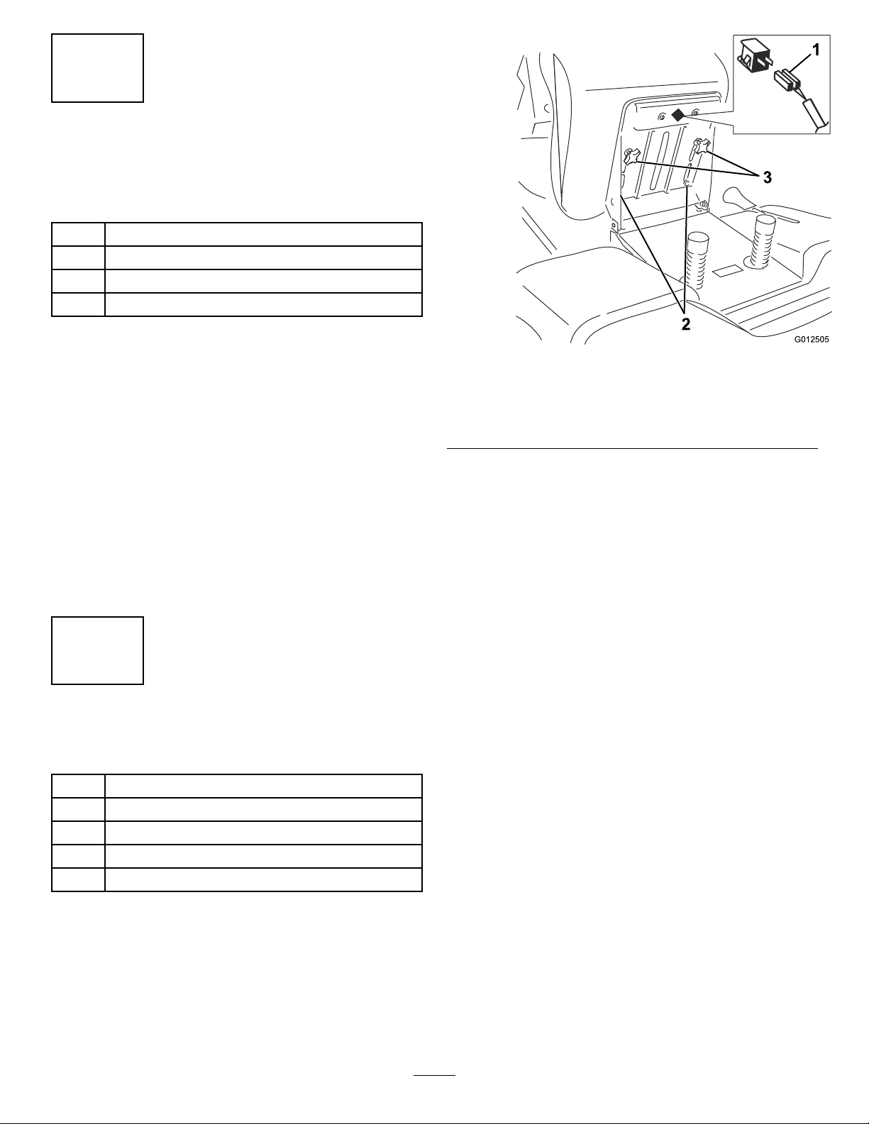
InstallingtheSeat
Partsneededforthisprocedure:
Figure1
1.Safetyswitch
2.Boltsandspacers
3.Installthe2adjustingknobsand2spring
washers(Figure1).
4.Ensurethatthesafetyswitchisconnectedto
theseat(Figure1).
3.Adjustingknobsand
springwashers
g012505
1
Seat
2Bolts
2Adjustingknob
2
Spacers
2
Springwashers
Procedure
1.Removetheplasticcoverfromtheseatand
discardit.
2.Settheseatinplaceandsecureitwiththe2
bolts,and2spacers(Figure1).
2
Page 3
3
AssemblingtheGrass
Collector
Partsneededforthisprocedure:
1
Collectorcover
1
Coverframe
1Handle
2
Springwasher
2Handlescrew
6
Screw
6
Steelwasher
12Rubberwasher
6Nut
1
Outerframe
2Hingepin
2
Snapring
1
Grasscollectordumplever
1
Grasscollectordumpleverscrew
Procedure
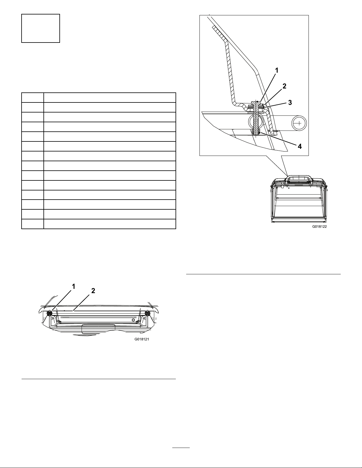
1.Alignthecollectorframewiththecollectorcover.
2.Insertthehandleintothehandleholesinthe
collectorcover(Figure2).
Figure3
Cross-sectionalviewshown
1.Screw3.Rubberwasher(2)
2.Steelwasher
4.Nut
5.Tightenthehandlescrewsthatyouloosely
installedinstep3.
g018122
Figure2
Cross-sectionalviewshown
1.Handle2.Fasteners
3.Installaspringwasherandascrewoneachend
ofthehandle,butdonottightenthescrews.
4.Startingfromthefrontandmovingrearward,
securethecollectorcovertotheframeat6
locationsusingascrew,1steelwasher,2rubber
washers,andanutateachlocation(Figure3).
6.Assembletheouterframetothecollectorframe
byinsertingahingepin(fromlooseparts)
throughtheholesoneachsidefrominsidethe
collector(Figure4).
g018121
3
Page 4

Figure4
4
CheckingtheOilLevel
NoPartsRequired
Procedure
Itmaybenecessarytoaddoiltothemachinebefore
rstoperation.RefertotheOperator’sManualfor
oiltype,viscosity,andcrankcasecapacity.Addonly
enoughoiltoraisetheleveltotheFullmarkonthe
dipstick.
g018123
1.Snapring
7.Secureahingepinoneachsideofthecollector
(ontheoutsideofthecollector),withasnapring
installedintothegrooveonthepin(Figure4).
8.Slidethehandlearmassemblyintoposition,
andsecureatthebottomofthegrasscollector
dumpleverwithascrew.
1.Grasscollectordumplever2.Screw
Note:Youmayneedtoadjusttheswitch
activationplatesothattheswitchoperates
properly.
2.Hingepin
Figure5
5
ActivatingtheBattery
NoPartsRequired
Procedure
1.Removethebatteryfromthemachine;referto
theOperator’sManual.
2.Removethellercapsfromthetopofthebattery.
DANGER
Batteryelectrolytecontainssulfuric
acid,whichisfatalifconsumedandcan
severelyburnyou.
•Donotdrinkelectrolyte.
•Avoidcontactwithskin,eyes,or
clothing.
•Wearsafetyglassestoshieldyour
eyesandrubberglovestoprotect
yourhands.
g018124
•Fillthebatterywherecleanwateris
availableforushingtheskin.
•Followallinstructionsandcomply
withallsafetymessagesonthe
electrolytecontainer.
3.Slowlypourelectrolyteintoeachcelluntilthe
levelisuptothelowerpartofthetube.
4.Leavethellercapsoff,andconnecta3to4A
batterychargertothebatteryposts.
5.Chargethebatteryatarateof2Aorlessforat
least24hours(12volts).
4
Page 5

Important:Useonlyabatterychargersetto
12voltstochargethebattery.
Important:Donotstarttheenginewith
abatterybooster(jumpstarter)pack.
Jump-startingtheenginewithabattery
boosterpackmaydamageelectronic
componentsofthemachine.
WARNING
Chargingthebatteryproducesgasses
thatcanexplode.
Neversmokenearthebattery,andkeep
sparksandamesawayfromthebattery.
6.Installthellercapsafterthebatteryisfully
charged.
7.Installthebatteryinthechassis;refertothe
Operator’sManual.
6
FillingtheFuelTank
8
LubricatingtheMachine
NoPartsRequired
Procedure
Ensurethatallofthenecessarypointsonthemachine
arelubricated;refertotheOperator’sManual.
9
CheckingtheSafetySystem
NoPartsRequired
Procedure
RefertotheOperator’sManual.
NoPartsRequired
Procedure
Addfueltothefueltank;refertotheOperator’s
Manual.
7
CheckingtheTirePressure
NoPartsRequired
Procedure
Checkfrontandreartiresforproperination;referto
theOperator’sManualfortherecommendedination
pressure.
5
Page 6

Notes:
Page 7

Notes:
Page 8

 Loading...