

Page 1

DH 200, DH 210, and DH 220
Lawn Tractors
Model No. 74570—Serial No. 250000001 and Up
Model No. 74571—Serial No. 250000001 and Up
Model No. 74590—Serial No. 250000001 and Up
Loose Parts
Note: Use the chart below to verify all parts have been shipped.
Description Qty. Use
Form No. 3352-926
Setup Instructions
Steering Wheel
Lock washer
Nut
Seat
Bolts
Flat Washers
Spring Washers
Trailer Hitch
Bolts
Washers
Nuts
Collector Cover
Grass Collector—Partially Assembled
Grass Bag
Fastener Package
Arrow Decal
Keys 2 Using in the ignition and Key Choice™ switch
Operator’s Manual
Engine Operator’s Manual
1
1
1
1
2
2
2
1
2
2
2
1
1
1
1
1
1
1
Installing the steering wheel
Installing the seat
Attaching the trailer hitch
Assembling the grass collector
Reading before operating the tractor
2004—The Toro Company
8111 Lyndale Ave., Bloomington, MN 55420, USA
Printed in the USA
All Rights Reserved
Register your product at www.Toro.com
Original Instructions (EN)
Page 2
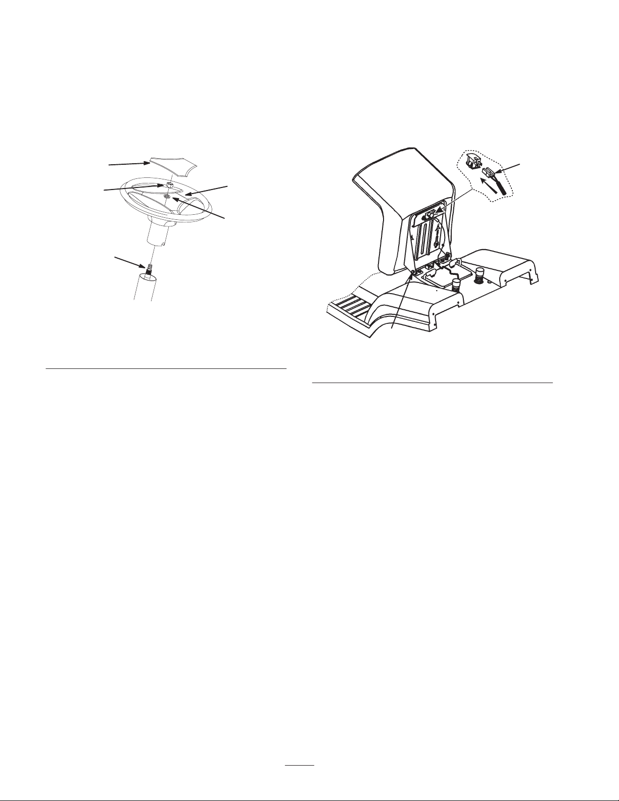
Installing the Steering Wheel
Installing the Seat
1. Position the front wheels straight ahead.
2. Remove the logo cover by releasing the 3 latches from
the back side with a screwdriver.
3. Line up the center spoke toward the seat and position
the steering wheel onto the shaft spline (Fig. 1).
5
4
1
3
2
2307
Figure 1
1. Center spoke
2. Shaft spline
3. Lock washer
4. Nut
5. Logo cover
1. Remove the plastic cover from the seat and discard it.
2. Loosen the two bolts on the tractor seat hinges.
3. Set the seat in place and secure it with the two bolts,
spring washers, and flat washers (Fig. 2).
1
2
Figure 2
1. Safety switch 2. Bolt and washers
4. Secure the steering wheel with a lock washer and nut
(Fig. 1).
5. Torque the steering wheel nut to 50 ft-lb (37 N.m).
6. Snap the logo cover into place (Fig. 1).
4. Connect the safety switch to the seat (Fig. 2).
2
Page 3

Attaching the Trailer Hitch
6. Insert the bottom tube into the bag (Fig. 4).
1. Line up the holes in the trailer hitch with the holes in
the tractor frame.
2. Attach the hitch with two bolts, washers, and nuts
(Fig. 3).
1
2
3
Figure 3
1. Trailer hitch
2. Bolt
3. Washer and nut
Assembling the Grass
Collector
1. Tilt the front tube of the partially assembled collector.
2. Align the upper holes with the holes on the upper tube.
Loosely fasten the tubes together with the upper bolts
(Fig. 4).
3. Place the collector on the rear tractor supports (refer to
the Operator’s Manual) and align the collector frame
with the tractor fenders.
4. Tighten the upper bolts (Fig. 4).
5. Stretch the bag and put it over the rear handle (Fig. 4).
11
1
10
2
12
3
7
4
5
6
9
8
Figure 4
1. Cover
2. Upper bolts
3. Front tube
4. M5 bolts and nuts
5. Left and right supports
6. Screws
7. Lower brace
8. Corner supports
9. Bottom tube
10. Bag
11. Dumping lever
12. Rear handle
7. Insert the corner supports under the top tube.
8. Fasten the corner supports to the top and bottom tubes
using the M5 bolts and nuts from under the collector
cover (Fig. 4).
9. Fasten the bottom tube to the front tube with M5 bolts
and nuts (Fig. 4).
4
10. Tilt the left and right supports rearward.
11. Place the lower brace on the outside of the bag and
secure it to the left and right supports with the screws
(Fig. 4).
12. Place the cover on the grass collector.
13. Align the cover with the rear fender by adjusting the
rear tractor supports until there is a proper seal
between the cover and the collector.
3
Page 4

14. Tighten the rear tractor support bolts.
15. Remove the grass collector from the tractor.
Warning
16. Tighten all screws securely.
17. Use the plastic extrusions on the bag edges to fix the
bag to the frame tube.
18. Insert the dumping lever through the hole of the cover
and secure it with the M5 x 12 screw and M5 nut
(inside the tube) (Fig. 4).
19. Install the grass collector to the tractor (refer to the
Operator’s Manual).
20. When the grass collector is properly positioned, place
the triangle symbol decal directly opposite the triangle
symbol on the rear of the tractor.
Checking the Oil Level
The tractor comes from the factory with oil in the engine
crankcase; however, it may be necessary to add oil. Refer
to the Operator’s Manual for oil type, viscosity, and
crankcase capacity. Add only enough oil to raise the level
to the Full mark on the dipstick.
Activating the Battery
1. Remove the battery from the tractor; refer to the
Operator’s Manual.
2. Remove the filler caps from the top of the battery.
Charging the battery produces gasses that can
explode.
Never smoke near the battery and keep sparks
and flames away from the battery.
6. Install the battery in the chassis; refer to the
Operator’s Manual.
Filling the Fuel Tank
Add fuel to the fuel tank; refer to the Operator’s Manual.
Checking the Tire Pressure
Check front and rear tires for proper inflation; refer to the
Operator’s Manual for the recommended inflation
pressure.
Lubricating the Tractor
Ensure that all of the necessary points on the tractor are
lubricated; refer to the Operator’s Manual.
Inserting the Keys into the
Switches
Danger
Battery electrolyte contains sulfuric acid that is
poisonous (if consumed) and can severely burn
you.
• Do not drink electrolyte.
• Avoid contact with skin, eyes or clothing.
• Wear safety glasses to shield your eyes and
rubber gloves to protect your hands.
• Fill the battery where clean water is available
for flushing the skin.
• Follow all instructions and comply with all
safety messages on the electrolyte container.
3. Slowly pour electrolyte into each cell until the level is
up to the lower part of the tube.
4. Leave the filler caps off and connect a 3- to 4-amp
battery charger to the battery posts.
5. Charge the battery at a rate of 2 amperes or less for
4 hours (12 volts). Do not overcharge the battery.
Install the filler caps after the battery is fully charged.
The Key Choice switch is located on the right side of seat
bracket below the seat.
Checking the Safety System
Refer to the Operator’s Manual.
Test Driving the Tractor
Ensure that all electrical and mechanical systems are
operating properly. Refer to the Operator ’s Manual for
how to properly operate the controls.
4
 Loading...