

Page 1
FormNo.3388-820RevA
g015545
GrandStand
With122cmTURBOFORCE
ModelNo.74568TE—SerialNo.315000001andUp
®
Mower
®
CuttingUnit
Registeratwww.T oro.com.
OriginalInstructions(EN)
*3388-820*A
Page 2
WARNING
g018327
CALIFORNIA
Proposition65Warning
Thisproductcontainsachemicalorchemicals
knowntotheStateofCaliforniatocausecancer,
birthdefects,orreproductiveharm.
Theengineexhaustfromthisproduct
containschemicalsknowntotheStateof
Californiatocausecancer,birthdefects,
orotherreproductiveharm.
ThisproductcomplieswithallrelevantEuropeandirectives;
fordetails,pleaseseetheseparateproductspecicDeclaration
ofConformity(DOC)sheet.
ThissparkignitionsystemcomplieswithCanadianICES-002.
Wheneveryouneedservice,genuineToroparts,oradditional
information,contactanAuthorizedServiceDealerorToro
CustomerServiceandhavethemodelandserialnumbersof
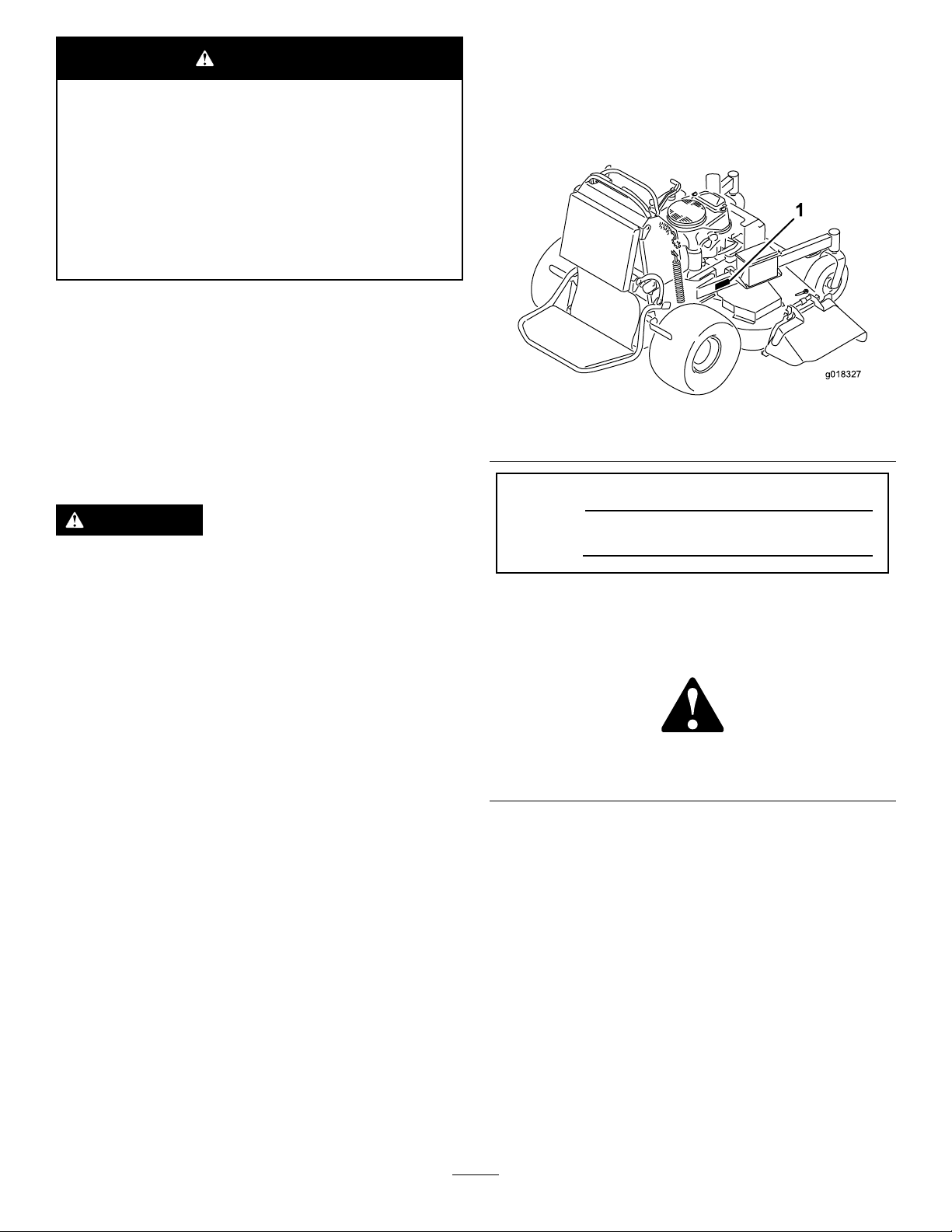
yourproductready.Figure1identiesthelocationofthe
modelandserialnumbersontheproduct.Writethenumbers
inthespaceprovided.
Important:Thisengineisnotequippedwithaspark
arrestermufer.ItisaviolationofCaliforniaPublic
ResourceCodeSection4442touseoroperatetheengine
onanyforest-covered,brush-covered,orgrass-covered
land.Otherstatesorfederalareasmayhavesimilarlaws.
WARNING
Removingstandardoriginalequipmentpartsand
accessoriesmayalterthewarranty,traction,and
safetyofthemachine.FailuretouseoriginalToro
partscouldcauseseriousinjuryordeath.Making
unauthorizedchangestotheengine,fuelorventing
system,mayviolateregulations.
Replaceallpartsincluding,butnotlimitedto,tires,
belts,blades,andfuelsystemcomponentswith
originalToroparts.
Introduction
Thisrotary-blade,ridinglawnmowerisintendedto
beusedbyprofessional,hiredoperatorsorresidential
homeowners.Itisdesignedprimarilyforcuttinggrass
onwell-maintainedlawnsonresidentialorcommercial
properties.Itisnotdesignedforcuttingbrushorfor
agriculturaluses.
Figure1
1.Locationofthemodelandserialnumbers
ModelNo.
SerialNo.
Thismanualidentiespotentialhazardsandhassafety
messagesidentiedbythesafetyalertsymbol(Figure2),
whichsignalsahazardthatmaycauseseriousinjuryordeath
ifyoudonotfollowtherecommendedprecautions.
Figure2
1.Safetyalertsymbol
Thismanualuses2wordstohighlightinformation.
Importantcallsattentiontospecialmechanicalinformation
andNoteemphasizesgeneralinformationworthyofspecial
attention.
Readthisinformationcarefullytolearnhowtooperateand
maintainyourproductproperlyandtoavoidinjuryand
productdamage.Youareresponsibleforoperatingthe
productproperlyandsafely.
YoumaycontactT orodirectlyatwww .Toro.comforproduct
andaccessoryinformation,helpndingadealer,ortoregister
yourproduct.
©2014—TheToro®Company
8111LyndaleAvenueSouth
Bloomington,MN55420
Contactusatwww.Toro.com.
2
PrintedintheUSA.
AllRightsReserved
Page 3

Contents
Safety...........................................................................4
SafeOperatingPractices...........................................4
ToroMowerSafety..................................................6
SoundPressure.......................................................7
SoundPower..........................................................7
VibrationLevel.......................................................7
SlopeIndicator.......................................................8
SafetyandInstructionalDecals.................................9
ProductOverview.........................................................14
Controls...............................................................14
Specications........................................................15
Operation....................................................................16
AddingFuel...........................................................16
CheckingtheEngine-OilLevel.................................17
BreakinginaNewMachine......................................17
ThinkSafetyFirst...................................................17
OperatingtheParkingBrake....................................18
OperatingtheMower-Blade-ControlSwitch
(PTO)...............................................................18
OperatingtheThrottle............................................19
OperatingtheChoke...............................................19
OperatingtheIgnitionSwitch..................................19
UsingtheFuelShut-offValve...................................20
StartingandStoppingtheEngine..............................20
TheSafety-InterlockSystem....................................21
OperatingthePlatform...........................................22
DrivingForwardorBackward..................................23
StoppingtheMachine.............................................24
UsingtheRotationIndicator....................................24
PushingtheMachinebyHand..................................25
TransportingtheMachine........................................25
LoadingtheMachine..............................................25
SideDischargingorMulchingtheGrass.....................26
AdjustingtheHeight-of-Cut....................................26
AdjustingtheFlowBafe........................................27
PositioningtheFlowBafe......................................27
UsingtheMid-SizeWeight.......................................28
Maintenance.................................................................29
RecommendedMaintenanceSchedule(s)......................29
PremaintenanceProcedures........................................30
RaisingtheMowerforAccess...................................30
ReleasingtheCushionforRearAccess.......................31
Lubrication...............................................................32
LubricatingtheMachine..........................................32
GreasingtheFrontCasterPivots..............................32
LubricatingtheCaster-WheelHubs...........................33
EngineMaintenance..................................................34
ServicingtheAirCleaner.........................................34
ServicingtheEngineOil..........................................34
ServicingtheSparkPlug..........................................37
CheckingtheSparkArrester(ifequipped)..................38
FuelSystemMaintenance...........................................38
DrainingtheFuelTank...........................................38
ServicingtheFuelFilter...........................................39
ElectricalSystemMaintenance....................................39
ServicingtheBattery...............................................39
ServicingtheFuses.................................................41
DriveSystemMaintenance.........................................41
AdjustingtheTracking...........................................41
CheckingtheTirePressure......................................43
AdjustingtheCaster-PivotBearing............................43
ServicingtheCasterWheelsandBearings...................43
AdjustingtheElectricClutch....................................44
CoolingSystemMaintenance......................................45
CleaningtheAir-IntakeScreen.................................45
CleaningtheCoolingSystem....................................45
BrakeMaintenance....................................................45
ServicingtheBrake.................................................45
BeltMaintenance......................................................47
ReplacingtheMower-DeckBelt...............................47
ReplacingthePump-DriveBelt................................48
ControlsSystemMaintenance.....................................49
AdjustingtheMotion-Control-Handle
Positions............................................................49
HydraulicSystemMaintenance....................................51
ServicingtheHydraulicSystem.................................51
MowerDeckMaintenance...........................................54
ServicingtheCuttingBlades.....................................54
CorrectingtheMowerQuality-of-Cut........................56
ReplacingtheGrassDeector..................................59
Cleaning...................................................................59
CleaningundertheMower.......................................59
DisposingofWaste.................................................59
Storage........................................................................60
CleaningandStorage..............................................60
Troubleshooting...........................................................61
Schematics...................................................................63
3
Page 4

Safety
Improperlyusingormaintainingthismowercanresult
ininjury.T oreducethepotentialforinjury,complywith
thesesafetyinstructions.
Torodesignedandtestedthismowerforreasonablysafe
service;however,failuretocomplywiththefollowing
instructionsmayresultinpersonalinjury.
Toensuremaximumsafety,bestperformance,and
togainknowledgeoftheproduct,itisessentialthat
youandanyotheroperatorofthemowerreadand
understandthecontentsofthismanualbeforethe
engineiseverstarted.Payparticularattentiontothe
safetyalertsymbol(Figure2)whichmeansCaution,
Warning,orDanger—“personalsafetyinstruction.”
Readandunderstandtheinstructionbecauseithasto
dowithsafety.Failuretocomplywiththeinstruction
mayresultinpersonalinjury.
SafeOperatingPractices
Thefollowinginstructionshavebeenadaptedfromthe
standardENISO5395:2013.
Training
Preparation
•Evaluatetheterraintodeterminewhataccessoriesand
attachmentsareneededtoproperlyandsafelyperform
thejob.Onlyuseaccessoriesandattachmentsapproved
bythemanufacturer.
•Wearappropriateclothing;includingahardhat,safety
glasses,longpants,substantial,slip-resistantfootwear,
gloves,andhearingprotection.
Important:Longhair,looseclothingorjewelrymay
gettangledinmovingparts.
•Inspecttheareawheretheequipmentistobeusedand
ensurethatallobjectsareremovedfromthemachine
beforeuse.
•Useextracarewhenhandlingfuels.Theyareammable
andvaporsareexplosive.
–Useonlyanapprovedcontainer.
–Donotremovethefuelcaporaddfuelwiththe
enginerunning.Allowtheenginetocoolbefore
refueling.Donotsmokenearthemachinewhenthe
engineisrunning.
–Donotrefuelordrainthemachineindoors.
•Checkthattheoperator'spresencecontrols,safety
switches,andshieldsareattachedandfunctioning
properly.Donotoperatethemachineunlesstheyare
functioningproperly.
•ReadtheOperator'sManualandothertrainingmaterial.
Note:Iftheoperator(s)ormechanic(s)cannotreadthe
manuallanguage,itistheowner'sresponsibilitytoexplain
thismaterialtothem.
•Becomefamiliarwiththesafeoperationoftheequipment,
operatorcontrols,andsafetysigns.
•Alloperatorsandmechanicsshouldbetrained.The
ownerisresponsiblefortrainingtheusers.
•Neverletchildrenoruntrainedpeopleoperateorservice
theequipment.
Note:Localregulationsmayrestricttheageofthe
operator.
•Theowner/usercanpreventandisresponsiblefor
accidentsorinjuriesoccurringtohimselforherself,other
people,ordamagetoproperty.
Operation
•Lightningcancausesevereinjuryordeath.Iflightning
isseen,orthunderisheardinthearea,donotoperate
themachine;seekshelter.
•Donotoperatetheengineinaconnedspacewhere
dangerouscarbonmonoxideandotherexhaustgasses
cancollect.
•Onlyoperateinwell-litareas,keepingawayfromholes
andhiddenhazards.
•Ensurethatalldrivesareinneutralandthattheparking
brakeisengagedbeforestartingengine.Onlystartthe
enginefromtheoperator’ sposition.
•Makesurethatyouhavegoodfootingwhileusingthis
machine,especiallywhenbackingup.
Note:Reducedfootingcouldcauseslipping.
•Slowdownanduseextracareonhillsides.Besureto
travelsidetosideonhillsides.Turfconditionscanaffect
thestabilityofthemachine.Usecautionwhileoperating
neardrop-offs.
•Slowdownandusecautionwhenmakingturnsandwhen
changingdirectionsonslopes.
•Donotraisethemowerdeckwiththebladesrunning.
•DonotoperatethemachinewithoutthePTOshieldor
otherguardssecurelyinplace.Besureallinterlocksare
attached,adjustedproperly ,andfunctioningproperly.
•Donotoperatewiththedischargedeectorraised,
removedoraltered,unlessusingagrasscatcher.
4
Page 5

•Donotchangetheenginegovernorsettingoroverspeed
theengine.
•Iffuelisspilledonclothing,changeyourclothing
immediately.
•Stoponlevelground,disengagedrives,engagethe
parkingbrake(ifprovided),shutofftheenginebefore
leavingtheoperator'spositionforanyreason,including
emptyingthecatchersoruncloggingthechute.
•Stopequipmentandinspectthebladesafterstriking
objectsorifanabnormalvibrationoccurs.Makethe
necessaryrepairsbeforeresumingoperations.
•Keepyourhandsandfeetawayfromthecuttingunit.
•Lookbehindanddownbeforebackinguptoensurea
clearpath.
•Keeppetsandbystandersawayfromanoperating
machine.
•Slowdownandusecautionwhenmakingturnsand
crossingroadsandsidewalks.Stopthebladesifyouare
notmowing.
•Beawareofthemower-dischargedirectionanddonot
pointitatanyone.
•Donotoperatethemowerundertheinuenceofalcohol
ordrugs.
•Usecarewhenloadingorunloadingthemachineinto
orfromatrailerortruck.
•Usecarewhenapproachingblindcorners,shrubs,trees,
orotherobjectsthatmayobscurevision.
SafeHandlingofFuels
•Toavoidpersonalinjuryorpropertydamage,use
extremecareinhandlinggasoline.Gasolineisextremely
ammableandthevaporsareexplosive.
•Extinguishallcigarettes,cigars,pipes,andothersources
ofignition.
•Donotoverllfueltank.Replacefuelcapandtighten
securely.
MaintenanceandStorage
•Disengagedrives,settheparkingbrake,stoptheengine,
andremovethekeyordisconnectspark-plugwire.W ait
forallmovementtostopbeforeadjusting,cleaning,or
repairing.
•Cleangrassanddebrisfromthecuttingunit,drives,
mufers,andenginetohelppreventres.
•Cleanupoilorfuelspillage.
•Lettheenginecoolbeforestoring.
•Donotstorefuelnearamesordrainindoors.
•Donotallowuntrainedpersonneltoservicemachine.
•Usejackstandstosupportcomponentswhenrequired.
•Carefullyreleasepressurefromcomponentswithstored
energy.
•Disconnectthebatteryorremovethespark-plugwire
beforemakinganyrepairs.Disconnectthenegative
terminalrstandthepositiveterminallast.Reconnect
thepositiverstandnegativelast.
•Usecarewhencheckingtheblades.Wraptheblade(s)or
weargloves,andusecautionwhenservicingthem.Only
replaceblades;donotstraightenorweldthem.
•Keephandsandfeetawayfrommovingparts.Ifpossible,
donotmakeadjustmentswiththeenginerunning.
•Keepallpartsingoodworkingconditionandallhardware
tightened.Replaceallwornordamageddecals.
•Useonlyanapprovedfuelcontainer.
•Donotremovethefuelcaporaddfuelwiththeengine
running.
•Allowtheenginetocoolbeforefueling.
•Donotfuelthemachineindoors.
•Donotstorethemachineorfuelcontainerwherethere
isanopename,spark,orpilotlightsuchasonawater
heateroronotherappliances.
•Donotllcontainersinsideavehicle,onatruck,orona
trailerbedwithaplasticliner.Alwaysplacecontainerson
thegroundawayfromyourvehiclebeforelling.
•Removeequipmentfromthetruckortrailerandfuelit
ontheground.Ifthisisnotpossible,thenaddfuelwith
suchequipmentasaportablecontainer,ratherthanfrom
afueldispensernozzle.
•Keepthenozzleincontactwiththerimofthefueltank
orcontaineropeningatalltimesuntilfuelingiscomplete.
Donotuseanozzlelockopendevice.
Hauling
•Usecarewhenloadingorunloadingthemachineintoa
traileroratruck.
•Usefull-widthrampsforloadingmachineintoatrailer
oratruck.
•Tiethemachinedownsecurelyusingstraps,chains,cable,
orropes.Bothfrontandrearstrapsshouldbedirected
downandoutwardfromthemachine.
5
Page 6

ToroMowerSafety
SlopeOperation
ThefollowinglistcontainssafetyinformationspecictoToro
productsandothersafetyinformationyoumustknow.
Thisproductiscapableofamputatinghandsandfeet,and
throwingobjects.Alwaysfollowallsafetyinstructionsto
avoidseriousinjuryordeath.
Thisproductisdesignedforcuttingandrecyclinggrass,or,
whenequippedwithagrassbagger,forcatchingcutgrass.
Anyuseforpurposesotherthanthesecouldprovedangerous
totheuserandbystanders.
GeneralOperation
•Besurethattheareaisclearofbystandersbeforemowing.
Stopthemachineifanyoneentersthearea.
•Donottouchequipmentorattachmentpartswhichmay
behotfromoperation.Allowallofthepartstocool
beforeattemptingtomaintain,adjust,orservicethe
machine.
•UseonlyToro-approvedattachments.W arrantymaybe
voidedifusedwithanyunapprovedattachments.
•Checkcarefullyforoverheadclearances(i.e.branches,
doorways,electricalwires,etc.)beforeoperatingunder
anyobjects,anddonotcontactthem.
•Slowdownbeforemakingturnsanduseextracaution.
•Usecautionwhenridingtheplatformovercurbs,rocks,
roots,orotherobstructions.
•Lookbehindanddownbeforebackinguptoensurea
clearpath.Useextracarewhenoperatinginreverse.
•Donotjerkthecontrols;useasteadymotion.
•Whenloadingorunloadingthemachine,useone
full-widthrampthatiswideenoughtoextendbeyond
thewidthofthemachine.
•Donotcarrypassengers.
•Donotcarryequipmentonthemachine.
Allslopesandrampsrequireextracaution.Ifyoufeeluneasy
onaslope,donotmowit.
•Removeobstaclessuchasrocks,treelimbs,etc.fromthe
mowingarea.
•Watchforholes,rutsorbumps.
Note:Tallgrasscanhideobstacles.
•Usecautionneardrop-offs,ditches,orembankments.
Note:Themachinecouldsuddenlyturnoverifawheel
goesovertheedgeofaclifforditch,orifanedgecavesin.
•Useextracarewithgrasscatchersorotherattachments.
Note:Thesecanchangethestabilityofthemachine.
•Keepallmovementonslopesslowandgradual.
•Donotmakesuddenchangesinspeedordirection.
•Mowslopessidetoside.
•Donotmowslopesgreaterthan20degrees.
Service
•Donotstorethemachineorafuelcontainerinsidewhere
thereisanopename,suchasnearawaterheateror
furnace.
•Keepthenutsandboltstight,especiallythe
blade-attachmentbolts.
•Neverremoveortamperwithsafetydevices.Checktheir
properoperationregularly.Neverdoanythingtointerfere
withtheintendedfunctionofasafetydeviceortoreduce
theprotectionprovidedbyasafetydevice.
•Tobestprotectyourinvestmentandmaintainoptimal
performanceofyourToroequipment,countonT oro
genuineparts.Whenitcomestoreliability,Torodelivers
replacementpartsdesignedtotheexactengineering
specicationsofourequipment.Forpeaceofmind,insist
onTorogenuineparts.
•Checkbrakeoperationfrequently.Adjustandserviceas
required.
6
Page 7

SoundPressure
Thisunithasasoundpressurelevelattheoperator’searof93
dBA,whichincludesanUncertaintyValue(K)of1dBA.
Thesoundpressurelevelwasdeterminedaccordingtothe
proceduresoutlinedinENISO5395:2013.
SoundPower
Thisunithasaguaranteedsoundpowerlevelof105dBA,
whichincludesanUncertaintyValue(K)of1dBA.
Thesoundpowerlevelwasdeterminedaccordingtothe
proceduresoutlinedinISO11094.
VibrationLevel
Hand-Arm
Measuredvibrationlevelforrighthand=1.1m/s
Measuredvibrationlevelforlefthand=0.8m/s
UncertaintyValue(K)=0.6m/s
Measuredvaluesweredeterminedaccordingtotheprocedures
outlinedinENISO5395:2013.
WholeBody
Measuredvibrationlevel=0.74m/s
UncertaintyValue(K)=0.37m/s
Measuredvaluesweredeterminedaccordingtotheprocedures
outlinedinENISO5395:2013.
2
2
2
2
2
7
Page 8
SlopeIndicator
G011841
Figure3
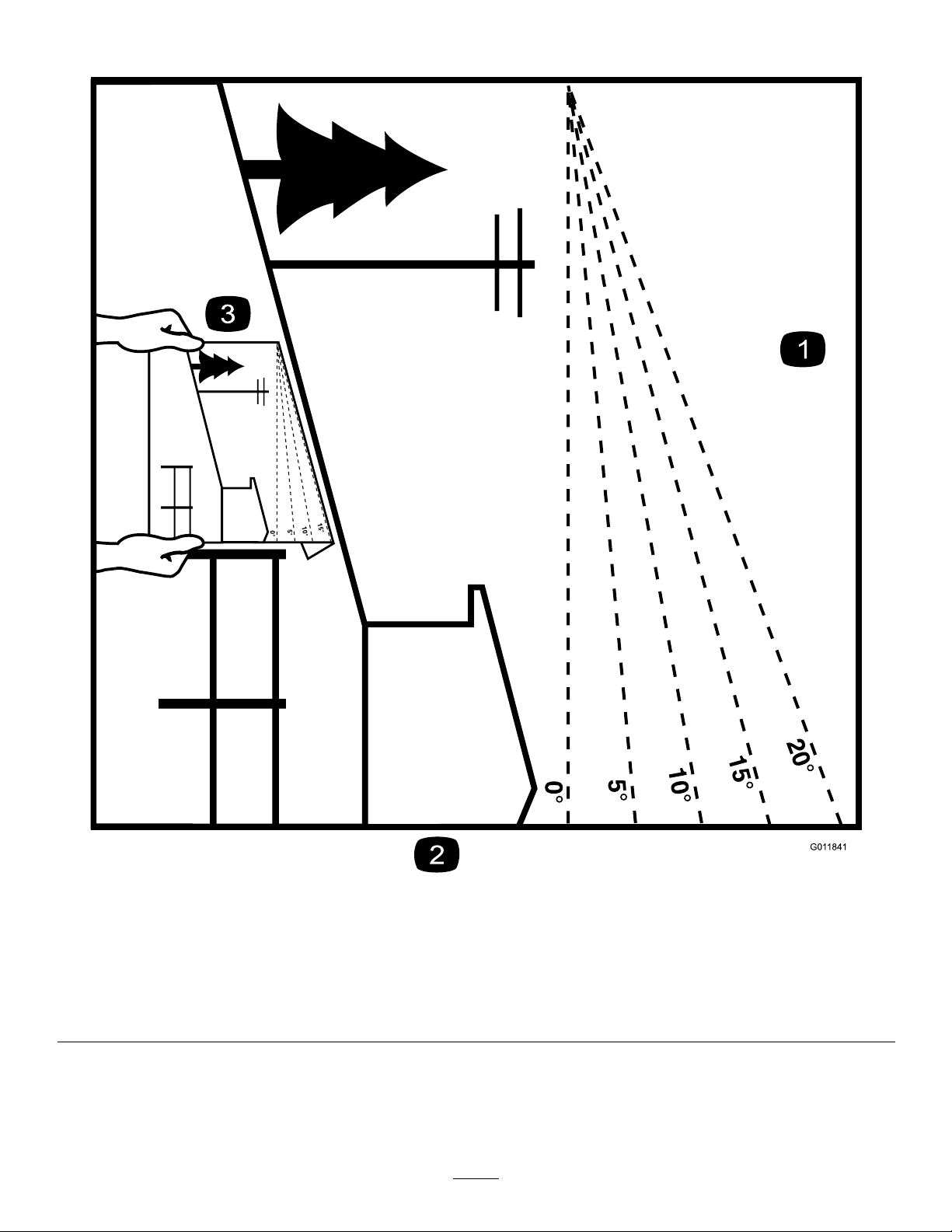
Thispagemaybecopiedforpersonaluse.
1.Themaximumslopeyoucansafelyoperatethemachineonis20degrees.Usetheslopecharttodeterminethedegreeofslope
ofhillsbeforeoperating.Donotoperatethismachineonaslopegreaterthan20degrees.Foldalongtheappropriateline
tomatchtherecommendedslope.
2.Alignthisedgewithaverticalsurface,atree,building,fencepole,etc.
3.Exampleofhowtocompareslopewithfoldededge.
8
Page 9
SafetyandInstructionalDecals
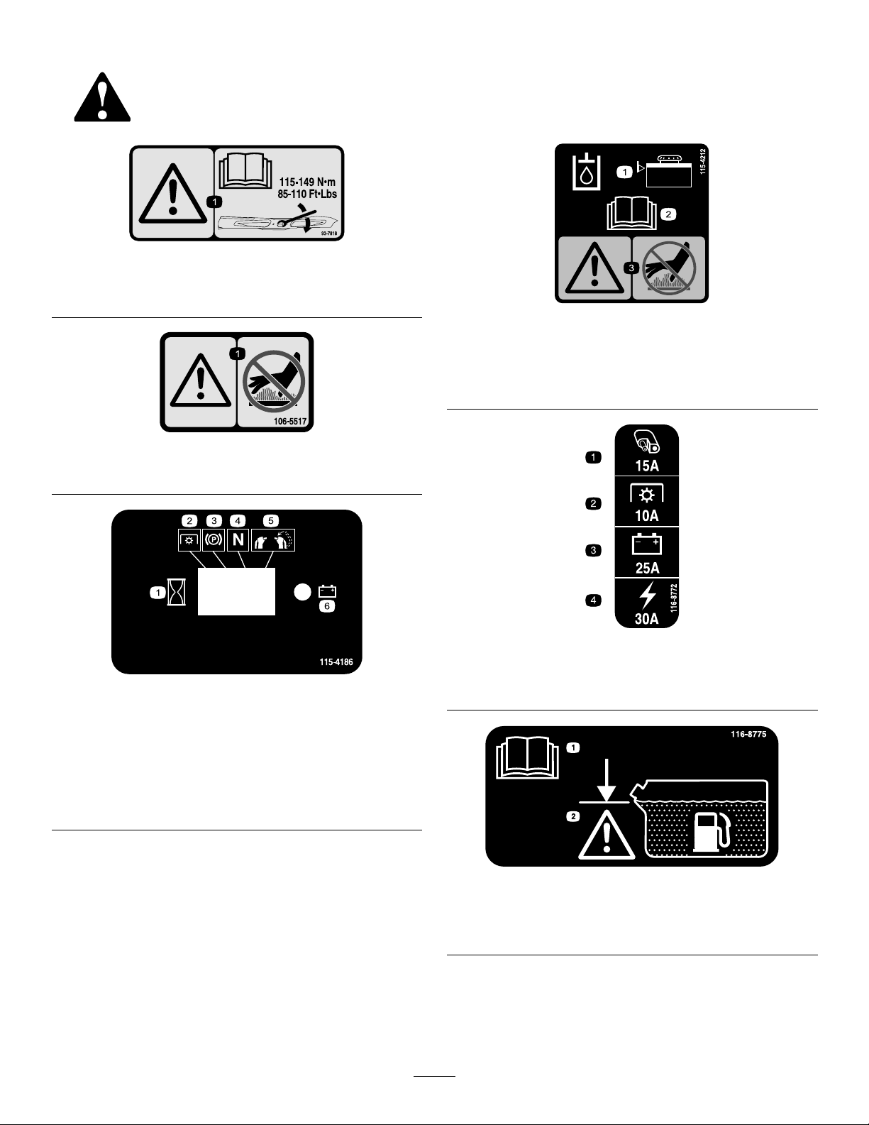
Safetydecalsandinstructionsareeasilyvisibletotheoperatorandarelocatednearanyareaofpotential
danger.Replaceanydecalthatisdamagedorlost.
93-7818
1.Warning—readtheOperator'sManualforinstructionson
torquingthebladebolt/nutto115-149N-m(85-110ft-lb).
115-4212
1.Warning–Donottouchthehotsurface.
1.Interval
2.PowerT ake-off(PTO)
3.Parkingbrake
4.Neutral
5.Operatorpresenceswitch
6.Battery
1.Hydraulicoillevel3.Warning—donottouchthe
2.ReadtheOperator's
Manual.
hotsurface.
106-5517
116-8772
1.Accessory,15A
115-4186
2.PTO,10A
3.Charge,25A
4.Main,30A
1.ReadtheOperator’s
Manual
9
116-8775
2.Filltobottomofllerneck;
warning—Donotoverll
thetank
Page 10
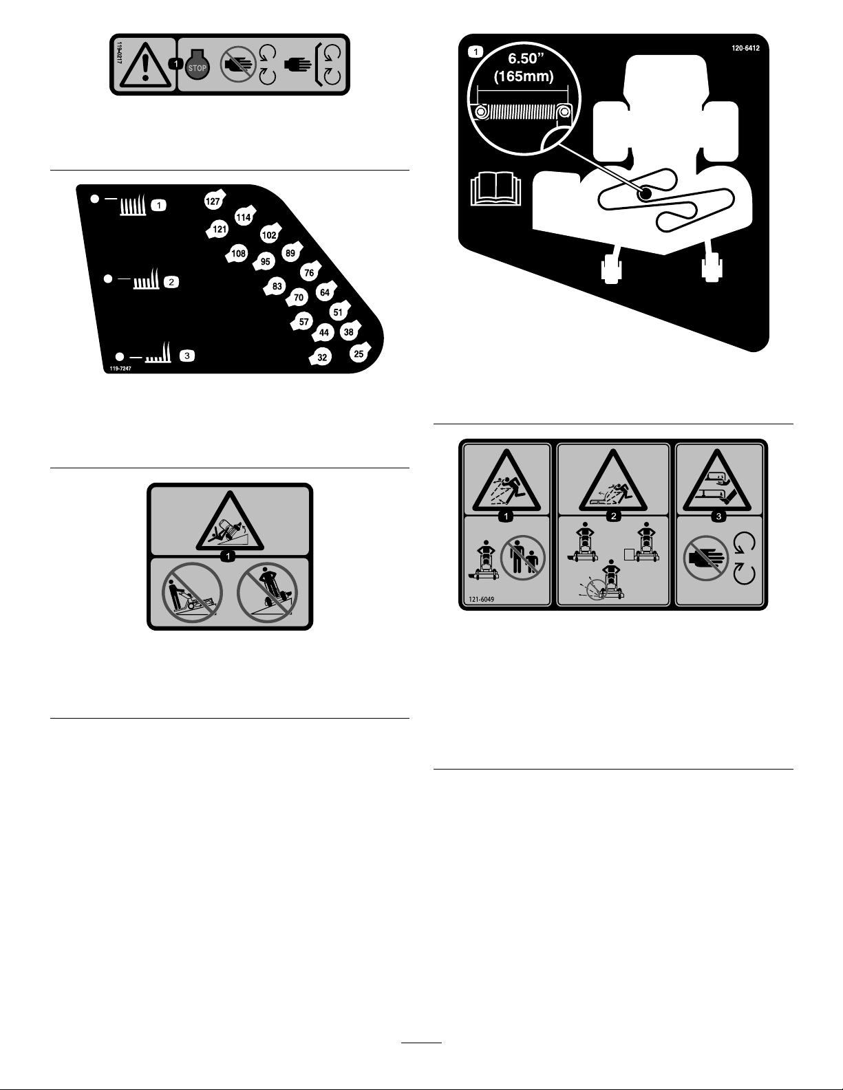
119-0217
119-8663
>10∞
>20∞
1.Warning—stoptheengine;stayawayfrommovingparts;
keepallguardsandshieldsinplace.
119-7247
1.Heightofcut(HOC)—high3.Heightofcut(HOC)—low
2.Heightofcut
(HOC)—medium
120-6412
1.Belttensionadjustment;readtheOperator'sManualfor
moreinformation.
119-8663
1.Tippinghazard—donotmowupordownslopesgreater
than10degrees;donotmowacrossslopesgreaterthan
20degrees.
1.Thrownobject
hazard—keepbystanders
awayfromthemachine.
2.Thrownobjecthazard,
mower—donotoperate
themowerwithguardsor
shieldsremoved.
121-6049
3.Cutting/dismemberment
hazardofhandorfoot,
mowerblade—keephands
awayfrommovingparts.
10
Page 11
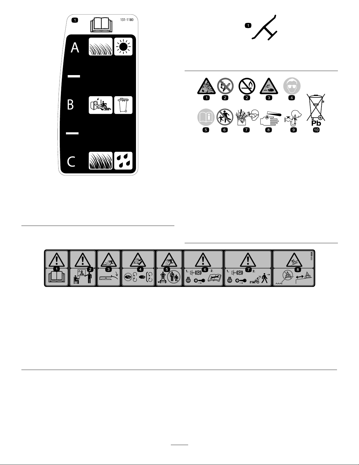
Manufacturer'sMark
1.Indicatesthebladeisidentiedasapartfromtheoriginal
machinemanufacturer.
BatterySymbols
Someorallofthesesymbolsareonyourbattery
1.ReadtheOperator's
Manual.
2.Short,lightgrass;dry
conditions;maximum
dispersion
131-1180
3.Baggingsetting
4.Tall,densegrass;wet
1.Explosionhazard
2.Nore,opename,or
smoking.
3.Causticliquid/chemical
burnhazard
conditions;maximum
groundspeed
4.Weareyeprotection9.Flusheyesimmediately
5.ReadtheOperator's
Manual.
6.Keepbystandersasafe
distancefromthebattery.
7.Weareyeprotection;
explosivegasescan
causeblindnessandother
injuries
8.Batteryacidcancause
blindnessorsevereburns.
withwaterandgetmedical
helpfast.
10.Containslead;donot
discard.
117-3626
1.Warning—readtheOperator'sManual.5.Thrownobjecthazard—keepbystandersasafedistancefrom
2.Warning—donotoperatethismachineunlessyouaretrained.6.Warning—engagetheparkingbrake,stoptheengine
3.Thrownobjecthazard—keepdeectorinplace.
4.Cutting,dismembermenthazardofhandorfoot—stayaway
frommovingpartsandkeepallguardsandshieldsinplace.
themachine.
andremovethesparkplugwirebeforeperformingany
maintenanceonthemachine.
7.Warning—engagetheparkingbrakeandstoptheengine
beforeleavingthemachine.
8.Slidingandlossofcontrolhazard—donotoperatethe
machineneardrop-offsorwater;keepasafedistancefrom
drop-offs.
11
Page 12
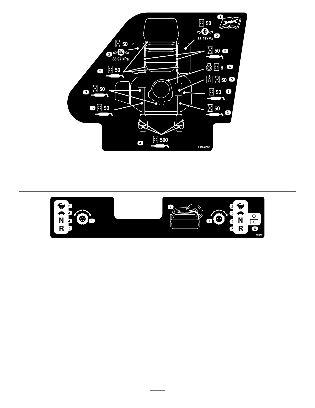
119-7285
1.ReadtheOperator'sManualbefore
performinganymaintenance.
2.Checkthedrivewheeltirepressure
every50hours
1.Tractioncontrol
2.Fast4.Neutral
3.Lubricateevery50hours
4.Lubricatethecasterwheelevery500
hours
5.Checkthehydraulicoilevery50hours
6.Checktheengineoilevery8hours
119-8727
3.Slow
5.Reverse
6.PowerT ake-off
(PTO)—disengage
7.Operatorpresenceswitch
12
Page 13

120-6464
1.Parkingbrake—engage
2.Parkingbrake—disengage
3.PowerT ake-off
(PTO)—engage
4.PowerT ake-off
(PTO)—disengage
5.Enginespeed
6.Fast
7.Continuousvariablesetting
8.Slow
13
Page 14
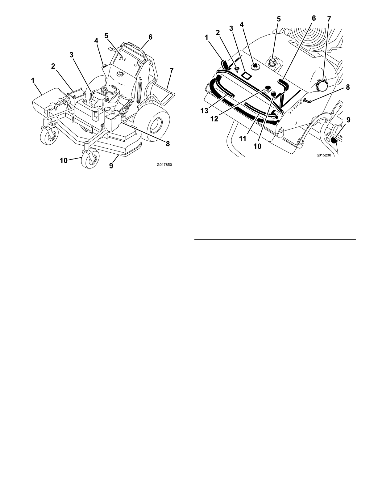
ProductOverview
G017850
g015230
3
4
5
6
7
8
9
10
11
12
13
Figure5
Figure4
1.Side-dischargechute6.Controllevers
2.Battery
3.Engine8.Hydraulictank
4.Fueltank9.Mowerdeck
5.Controls
7.Platform(downposition)
10.Frontcasterwheel
Controls
Becomefamiliarwithallthecontrols(Figure5)beforeyou
starttheengineandoperatethemachine.
1.Parking-brakelever
2.Choke9.Platformlatch
3.Hourmeter10.Throttlecontrol
4.Ignitionswitch11.Rightmotion-controllever
5.Fuelgauge12.Blade-controlswitch
6.Height-of-cutlever13.Leftmotion-controllever
7.Fuelcap
8.Height-of-cutpin
(PTO)
HourMeter
Thehourmeterrecordsthenumberofhourstheenginehas
operated.Itoperateswhentheengineisrunning.Usethese
timesforschedulingregularmaintenance(Figure6).
FuelGauge
Thefuelgaugeislocatedonthetop,middleofthetank
(Figure5).
Safety-InterlockIndicators
Therearesymbolsonthehourmeterandindicatewitha
blacktrianglethattheinterlockcomponentisinthecorrect
position(Figure6).
14
Page 15
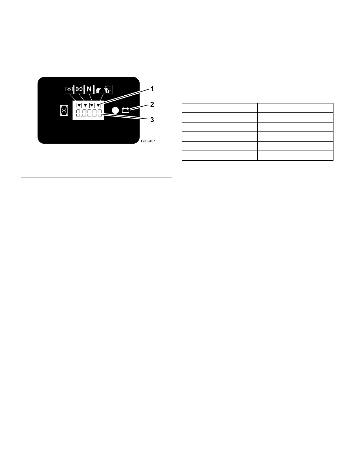
Battery-IndicatorLight
Attachments/Accessories
IftheignitionkeyisturnedtotheOnpositionforafew
seconds,thebatteryvoltagewillbedisplayedinthearea
wherethehoursarenormallydisplayed.
Thebatterylightturnsonwhentheignitionisturnedonand
whenthechargeisbelowthecorrectoperatinglevel(Figure
6).
Figure6
1.Safety-interlocksymbols
2.Batterylight
3.Hourmeter
ThrottleControl
AselectionofToroapprovedattachmentsandaccessoriesis
availableforusewiththemachinetoenhanceandexpand
itscapabilities.ContactyourAuthorizedServiceDealeror
Distributororgotowww .Toro.comforalistofallapproved
attachmentsandaccessories.
Specications
Note:Specicationsanddesignaresubjecttochange
withoutnotice.
Cuttingwidth122cm(48.0inches)
Widthwithdeectordown161.3cm(63.5inches)
Lengthwithplatformdown188cm(74inches)
Lengthwithplatformup147.3cm(58inches)
Height
Weight
121.9cm(48inches)
399.6kg(881lbs)
ThethrottlecontrolisvariablebetweenFastandSlow.
Choke
Usethechoketostartacoldengine.
Blade-ControlSwitch(PTO)
Theblade-controlswitch(PTO)isusedtoengagethe
electricclutchtodrivethemowerbladeswiththerightside
motion-controlleverinthecenter,unlockedposition.Pull
theswitchuptoengagethebladesandrelease.Todisengage
theblades,pushtheblade-controlswitch(PTO)downor
moveorreleasetherightsidemotion-controlleverintothe
neutral-lockposition.
IgnitionSwitch
Thisswitchisusedtostartthemowerengineandhasthree
positions:Off,RunandStart.
Motion-ControlLevers
Themotion-controlleversareusedtodrivethemachine
forward,reverse,andturneitherdirection.
FuelShut-offValve
Closethefuelshut-offvalve(locatedbehindtheoperator
cushionontherighthandsideofthefueltank)when
transportingorstoringthemower.
15
Page 16

Operation
Note:Determinetheleftandrightsidesofthemachine
fromthenormaloperatingposition.
AddingFuel
•Forbestresults,useonlyclean,fresh(lessthan30days
old),unleadedgasolinewithanoctaneratingof87or
higher((R+M)/2ratingmethod).
•Ethanol:Gasolinewithupto10%ethanol(gasohol)
or15%MTBE(methyltertiarybutylether)byvolume
isacceptable.EthanolandMTBEarenotthesame.
Gasolinewith15%ethanol(E15)byvolumeisnot
approvedforuse.Neverusegasolinethatcontains
morethan10%ethanolbyvolume,suchasE15
(contains15%ethanol),E20(contains20%ethanol),or
E85(containsupto85%ethanol).Usingunapproved
gasolinemaycauseperformanceproblemsand/orengine
damagewhichmaynotbecoveredunderwarranty.
•Donotusegasolinecontainingmethanol.
•Donotstorefueleitherinthefueltankorfuelcontainers
overthewinterunlessafuelstabilizerisused.
•Donotaddoiltogasoline.
DANGER
Incertainconditionsduringfueling,static
electricitycanbereleasedcausingasparkwhich
canignitethegasolinevapors.Areorexplosion
fromgasolinecanburnyouandothersandcan
damageproperty.
•Alwaysplacegasolinecontainersontheground
awayfromyourvehiclebeforelling.
•Donotllgasolinecontainersinsideavehicleor
onatruckortrailerbedbecauseinteriorcarpets
orplastictruckbedlinersmayinsulatethe
containerandslowthelossofanystaticcharge.
•Whenpractical,removegas-poweredequipment
fromthetruckortrailerandrefueltheequipment
withitswheelsontheground.
•Ifthisisnotpossible,thenrefuelsuch
equipmentonatruckortrailerfromaportable
container,ratherthanfromagasolinedispenser
nozzle.
•Ifagasolinedispensernozzlemustbeused,
keepthenozzleincontactwiththerimofthe
fueltankorcontaineropeningatalltimesuntil
fuelingiscomplete.
DANGER
Incertainconditions,gasolineisextremely
ammableandhighlyexplosive.Areorexplosion
fromgasolinecanburnyouandothersandcan
damageproperty.
•Fillthefueltankoutdoors,inanopenarea,
whentheengineiscold.Wipeupanygasoline
thatspills.
•Neverllthefueltankinsideanenclosedtrailer.
•Donotllthefueltankcompletelyfull.Add
gasolinetothefueltankuntilthelevelis6to13
mm(1/4to1/2inch)belowthebottomofthe
llerneck.Thisemptyspaceinthetankallows
gasolinetoexpand.
•Neversmokewhenhandlinggasoline,andstay
awayfromanopenameorwheregasoline
fumesmaybeignitedbyaspark.
•Storegasolineinanapprovedcontainerand
keepitoutofthereachofchildren.Neverbuy
morethana30-daysupplyofgasoline.
•Donotoperatewithoutentireexhaustsystemin
placeandinproperworkingcondition.
WARNING
Gasolineisharmfulorfatalifswallowed.Long-term
exposuretovaporscancauseseriousinjuryand
illness.
•Avoidprolongedbreathingofvapors.
•Keepfaceawayfromnozzleandgastankor
conditionerbottleopening.
•Avoidcontactwithskin;washoffspillagewith
soapandwater.
UsingStabilizer/Conditioner
Useafuelstabilizer/conditionerinthemachinetoprovide
thefollowingbenets:
•Keepsgasolinefreshduringstorageof90daysorless.
Forlongerstorageitisrecommendedthatthefueltank
bedrained.
•Cleanstheenginewhileitruns
•Eliminatesgum-likevarnishbuildupinthefuelsystem,
whichcauseshardstarting
Important:Donotusefueladditivescontaining
methanolorethanol.
Addthecorrectamountofgasstabilizer/conditionerto
thegas.
Note:Afuelstabilizer/conditionerismosteffective
whenmixedwithfreshgasoline.Tominimizethechance
16
Page 17
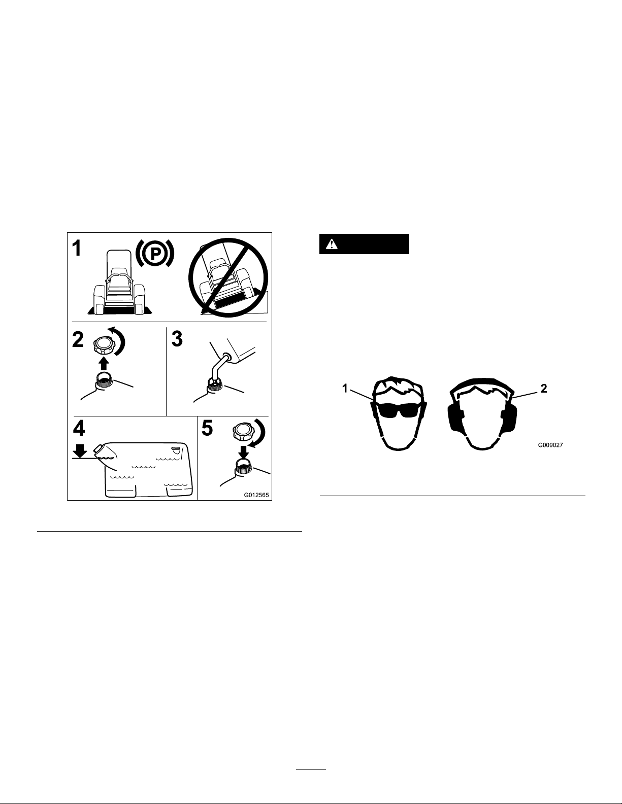
ofvarnishdepositsinthefuelsystem,usefuelstabilizer
2
4
3
G012565
1
5
G009027
1
2
atalltimes.
FillingtheFuelTank
Note:Donotllthefueltankcompletelyfull.Fillthefuel
tanktothebottomofthellerneck.Theemptyspaceinthe
tankallowsthegasolinetoexpand.
BreakinginaNewMachine
Newenginestaketimetodevelopfullpower.Mowerdecks
anddrivesystemshavehigherfrictionwhennew ,placing
additionalloadontheengine.Allow40to50hoursof
break-intimefornewmachinestodevelopfullpowerand
bestperformance.
1.Parkthemachineonlevelground.
2.Shuttheengineoffandsettheparkingbrake.
3.Cleanaroundthefuel-tankcap.
4.Fillthefueltanktothebottomofthellerneck.
Ensurethereisemptyspaceinthetanktoallowthe
gasolinetoexpand(Figure7).
ThinkSafetyFirst
Carefullyreadallthesafetyinstructionsanddecalsinthe
safetysection.Knowingthisinformationcouldhelpyouor
anybystandersavoidinjury.
Theuseofprotectiveequipmentforeyes,hearing,feetand
headisrecommended.
CAUTION
Thismachineproducessoundlevelsinexcessof
85dBAattheoperator'searandcancausehearing
lossthroughextendedperiodsofexposure.
Wearhearingprotectionwhenoperatingthis
machine.
Theuseofprotectiveequipmentforeyes,ears,feet,andhead
isrecommended.
Figure8
1.Wearsafetyglasses
Figure7
2.Wearhearingprotection
CheckingtheEngine-OilLevel
Beforeyoustarttheengineandusethemachine,check
theoillevelintheenginecrankcase;refertoCheckingthe
Engine-OilLevel(page35).
17
Page 18
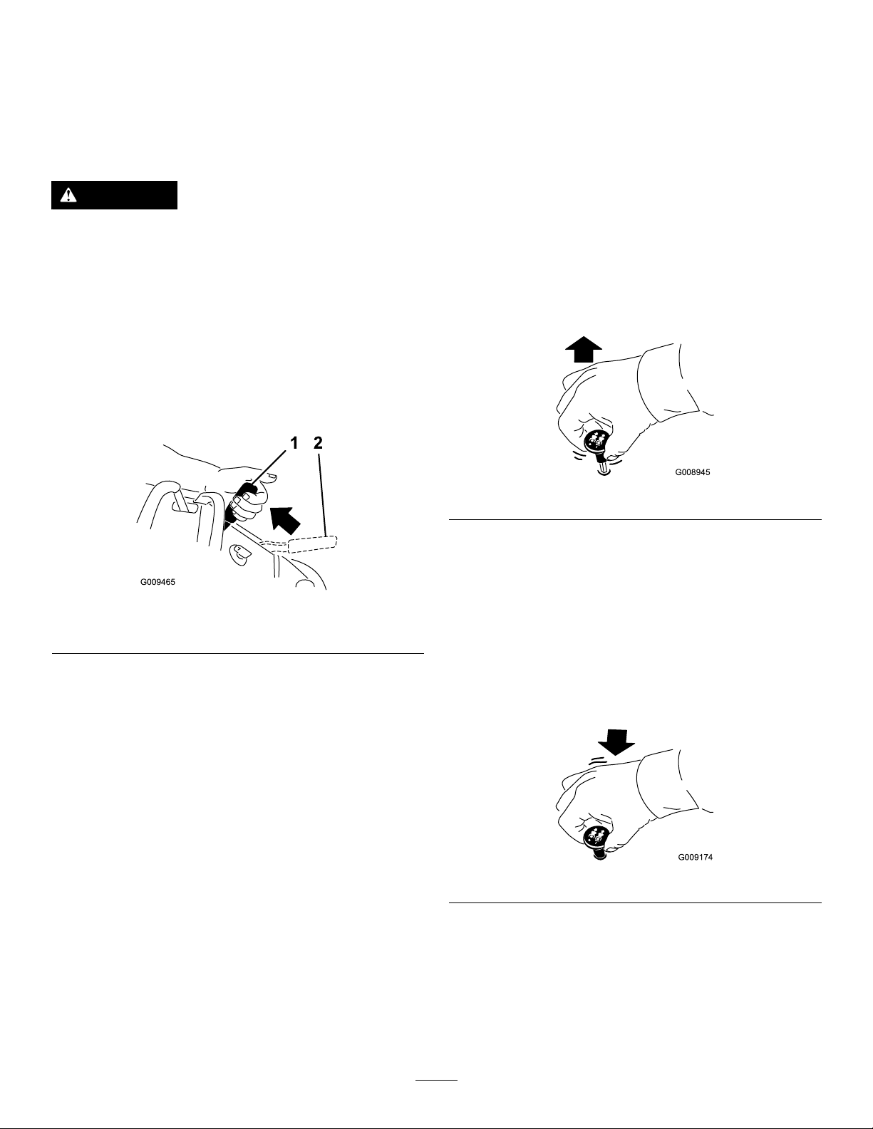
OperatingtheParkingBrake
G008945
G009174
Operatingthe
Alwayssettheparkingbrakewhenyoustopthemachineor
leaveitunattended.Beforeeachuse,checktheparkingbrake
forproperoperation.
Iftheparkingbrakedoesnotholdsecurely,adjustit;referto
ServicingtheBrake(page45).
CAUTION
Childrenorbystandersmaybeinjuredifthey
moveorattempttooperatethemachinewhileitis
unattended.
Alwaysremovetheignitionkeyandsettheparking
brakewhenleavingthemachineunattended,even
ifjustforafewminutes.
SettingtheParkingBrake
Pulltheparking-brakeleverrearwardandoverintoengaged
position(Figure9).
Mower-Blade-ControlSwitch
(PTO)
Theblade-controlswitch(PTO)isusedinconjunctionwith
therightsidemotion-controllevertoengageanddisengage
themowerblades.
EngagingtheMowerBlades(PTO)
1.Toengagethemowerblades,movetherightside
motion-controllevertothecenter,unlockedposition.
2.Pulltheblade-controlswitch(PTO)upandreleaseit
whileholdingdowntherightsidemotion-controllever
inthecenter,unlockedposition.
Figure10
Figure9
1.Parkingbrakeengaged2.Parkingbrakereleased
ReleasingtheParkingBrake
Pullthebrakeleverbackandoverintotheslotandpushthe
parking-brakeleverforward.
DisengagingtheMowerBlades(PTO)
Thefollowingaretwooptionsfordisengagingthemower
blades.
•Pushtheblade-controlswitch(PTO)downtotheOff
position.
•Movethemotion-controlleverstoneutralandmove
therightsidemotion-controlleverintotheneutral-lock
position.
Figure11
18
Page 19
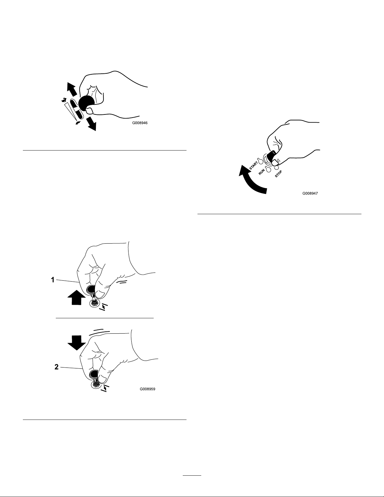
OperatingtheThrottle
G008946
G008959
1
2
START
RUN
STOP
G008947
OperatingtheIgnitionSwitch
ThethrottlecontrolcanbemovedbetweenFastandSlow
positions(Figure12).
Alwaysusethefastpositionwhenturningonthemowerdeck
withtheblade-controlswitch(PTO).
Figure12
OperatingtheChoke
Usethechoketostartacoldengine.
1.Iftheengineiscold,usethechoketostarttheengine.
2.Pulluponthechokeknobtoengagethechokebefore
usingtheignitionswitch(Figure13).
3.Pushdownonthechoketodisengagethechokeafter
theenginehasstarted(Figure13).
1.TurntheignitionkeytotheStartposition(Figure14).
Whentheenginesstarts,releasethekey.
Important:Donotengagestarterformorethan5
secondsatatime.Iftheenginefailstostartallow
a15secondcool-downperiodbetweenattempts.
Failuretofollowtheseinstructionscanburnout
thestartermotor.
Note:Additionalstartingcyclesmayberequired
whenstartingtheengineforthersttimeafterthefuel
systemhasbeenwithoutfuelcompletely.
Figure14
2.Turntheignitionkeytostoptostoptheengine.
Figure13
1.Onposition2.Offposition
19
Page 20
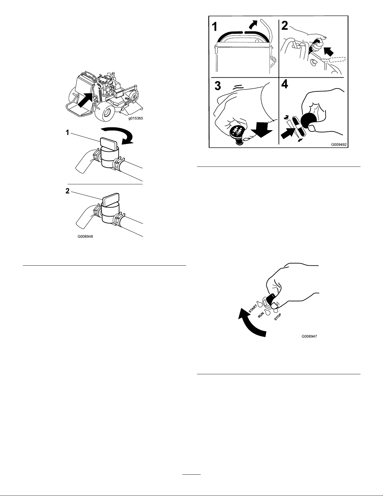
UsingtheFuelShut-offValve
g015365
G008948
1
2
START
RUN
STOP
G008947
Closethefuelshut-offvalvefortransport,maintenance,and
storage(Figure15).
Ensurethefuelshut-offvalveisopenwhenstartingthe
engine.
Figure16
7.TurntheignitionkeytotheStartposition(Figure17).
Whentheenginesstarts,releasethekey.
Important:Donotengagethestarterformore
than5secondsatatime.Iftheenginefailsto
start,allowa15secondcool-downperiodbetween
attempts.Failuretofollowtheseinstructionscan
burnoutthestartermotor.
Figure15
1.Onposition2.Offposition
Note:Additionalstartingcyclesmayberequired
whenstartingtheengineforthersttimeafterthefuel
systemhasbeenwithoutfuelcompletely.
StartingandStoppingthe Engine
StartingtheEngine
1.Connectthewirestothesparkplugs.
2.Openthefuelvalve.
3.Movetherightmotion-controllevertoneutrallocked
position.
1.Offposition3.Startposition
2.Runposition
4.Settheparkingbrake;refertoSettingtheParking
Brake(page18).
5.Movetheblade-controlswitch(PTO)totheOff
position.
6.MovethethrottlelevermidwaybetweentheSlowand
Fastpositions.
Figure17
Note:Awarmorhotenginemaynotrequirechoking.
20
Page 21
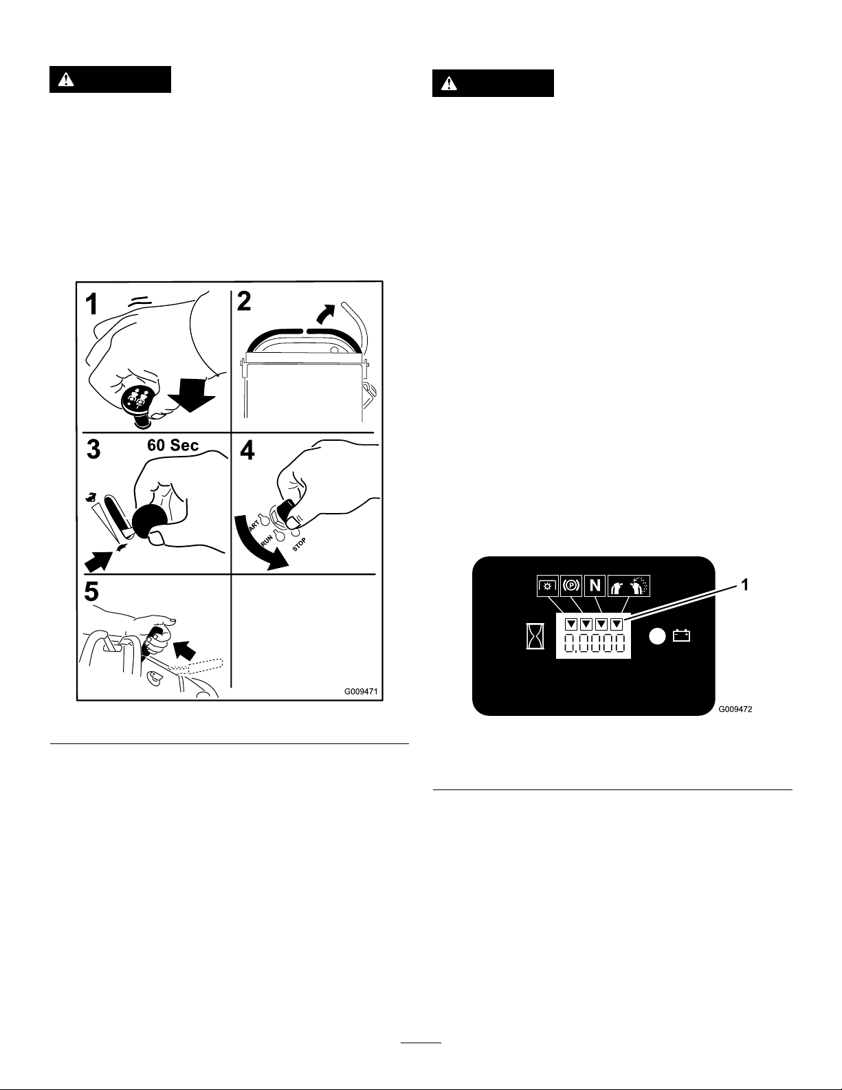
StoppingtheEngine
TheSafety-InterlockSystem
CAUTION
Childrenorbystandersmaybeinjuredifthey
moveorattempttooperatethetractorwhileitis
unattended.
Alwaysremovetheignitionkeyandsettheparking
brakewhenleavingthemachineunattended,even
ifjustforafewminutes.
Lettheengineidleatslowthrottle(turtle)for60seconds
beforeturningtheignitionswitchoff.
CAUTION
Ifsafety-interlockswitchesaredisconnectedor
damagedthemachinecouldoperateunexpectedly
causingpersonalinjury.
•Donottamperwiththeinterlockswitches.
•Checktheoperationoftheinterlockswitches
dailyandreplaceanydamagedswitchesbefore
operatingthemachine.
UnderstandingtheSafety-Interlock
System
Thesafety-interlocksystemisdesignedtopreventthemower
bladesfromrotatingunless:
•Therightsidemotion-controlleverismovedtothe
center,unlockedposition.
•Theblade-controlswitch(PTO)ispulledon.
Thesafety-interlocksystemisdesignedtostopthemower
bladesifyoumoveorreleasetherightsidemotion-control
leverintotheneutral-lockposition.
Figure18
Important:Makesurethatthefuelshut-offvalveis
closedbeforetransportingorstoringthemachine,as
fuelleakagemayoccur.Beforestoringthemachine,pull
wireoffsparkplug(s)topreventpossibilityofaccidental
starting.
Thehourmeterhassymbolstonotifytheuserwhenthe
interlockcomponentisinthecorrectposition.Whenthe
componentisinthecorrectposition,atrianglewilllight
upinthecorrespondingsquare.
Figure19
1.Triangleslightupwhentheinterlockcomponentsareinthe
correctposition
21
Page 22

TestingtheSafety-InterlockSystem
ServiceInterval:Beforeeachuseordaily
Testthesafety-interlocksystembeforeyouusethemachine
eachtime.
Note:Ifthesafetysystemdoesnotoperateasdescribed
below,haveanAuthorizedServiceDealerrepairthesafety
systemimmediately.
1.Starttheengine;refertoStartingtheEngine(page20).
2.Settheparkingbrake.
3.Movetherightsidemotion-controllevertothecenter,
unlockedposition.
Note:Thebladesshouldnotrotate.
4.Movethemotion-controlleversforward.
Note:Theengineshouldstoprunning.
5.Starttheengineandreleasetheparkingbrake.
6.Movetherightsidemotion-controllevertothecenter,
unlockedposition.
7.Continueholdingtherightsidemotion-controllever
inthecenter,unlockedposition,pulluponthe
blade-controlswitch(PTO),andrelease.
Note:Theclutchshouldengageandthemower
bladesrotate.
WARNING
Theoperatorplatformisheavyandmaycause
injurywhenloweringandraisingtheoperator
platform.Theplatformmaysuddenlydropifnot
supportedwhenthelatchpinispulledout.
•Donotputyourhandsorngersinthe
platform-pivotareawhenloweringorraisingthe
operatorplatform.
•Makesuretheplatformissupportedwhenthe
latchpinispulledout.
•Makesurethelatchsecurestheplatformwhen
foldingitintheupposition.Pushittightagainst
thecushionforthelatchpintolockintoplace.
•Keepbystandersawaywhenraisingorlowering
theplatform.
OperatingthePlatform
Themachinecanbeusedwiththeplatformintheupordown
position.Itistheoperator'spreferenceonwhichposition
touse.
OperatingtheMachinewiththe
PlatformUp
8.Moveorreleasetherightsidemotion-controlleverinto
theneutral-lockposition.
Note:Thebladesshouldstoprotatingandtheengine
continuestorun.
9.Pushtheblade-controlswitchdownandmovethe
rightsidemotion-controllevertothecenter,unlocked
position.
10.Continueholdingtherightsidemotion-controllever
inthecenter,unlockedposition,pulluponthe
blade-controlswitch(PTO),andrelease.
Note:Theclutchshouldengageandthemower
bladesrotate.
11.Pushtheblade-controlswitch(PTO)downtotheOff
position.
Note:Thebladesshouldstoprotating.
12.Withtheenginerunning,pulluptheblade-control
switch(PTO)andreleaseitwithoutholdingrightside
motion-controllevertothecenter,unlockedposition.
Note:Thebladesshouldnotrotate.
Operatingthemachinewiththeplatformupisrecommended
forthefollowing:
•Mowingneardrop-offs
•Mowingsmallareaswherethemachineistoolarge
•Areaswithlow ,over-hangingbranchesorobstacles
•Loadingthemachinefortransport
•Drivingupslopes
Toraisetheplatform,pullthebackoftheplatformupsothat
thelatchpinandknoblockitintoplace.Pushittightagainst
thecushionforthelatchpintolockitintoplace.
OperatingtheMachinewiththe
PlatformDown
Operatingthemachinewiththeplatformdownis
recommendedforthefollowing:
•Mowingmostareas
•Drivingacrossslopes
•Drivingdownslopes
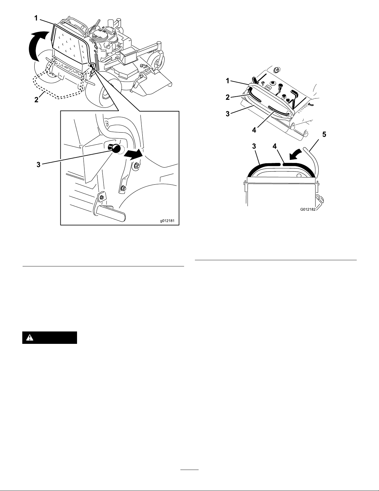
Tolowertheplatform,pushtheplatformforwardagainstthe
cushiontoreleasepressureonthelatchpin,thenpullthe
knobout,andlowertheplatform(Figure20).
22
Page 23
DrivingForward
G012182
4
5
1
2
3
3 4
1.Releasetheparkingbrake;refertoReleasingthe
ParkingBrake(page18).
2.Movetherightsidemotion-controllevertothecenter,
unlockedposition.
Figure21
4.Rightcontrollever
5.Rightcontrolleverinthe
neutrallockposition
1.Platformup
2.Platformdown
Figure20
3.Pulltheknobouttorelease
theplatform.
1.Frontreferencebar
2.Leftcontrollever
3.Rearreferencebar
3.Togoforward,movethespeed-controllevertothe
desiredspeed.
DrivingForwardorBackward
Thethrottlecontrolregulatestheenginespeedasmeasured
inrpm(revolutionsperminute).Placethethrottlecontrolin
theFastpositionforbestperformance.Alwaysoperatethe
4.Slowlypushthemotion-controlleversforward(Figure
22).
Note:Theenginewillkillifamotion-controlleveris
movedwiththeparkingbrakeengaged.
machineinthefullthrottlepositionwhenmowing.
Note:Thefartheryoumovethemotion-controllevers
CAUTION
ineitherdirection,thefasterthemachinewillmove
inthatdirection.
Themachinecanspinveryrapidly.Theoperator
maylosecontrolofmachine,andmaycause
personalinjuryordamagetomachine.
Slowthemachinedownbeforemakingsharpturns.
Note:Tostop,pullthemotion-controlleversbackto
theneutralposition.
23
Page 24
StoppingtheMachine
G015493
1
1 2
1
Tostopthemachine,movethemotioncontrolleversto
neutral,movetherightsidemotioncontrolleverintothe
neutrallockposition,disengagethepowertakeoff(PTO),
andturntheignitionkeytooff.
Settheparkingbrakewhenyouleavethemachine;referto
SettingtheParkingBrake(page18).Remembertoremove
thekeyfromtheignitionswitch.
CAUTION
Childrenorbystandersmaybeinjuredifthey
moveorattempttooperatethetractorwhileitis
unattended.
Alwaysremovetheignitionkeyandsettheparking
brakewhenleavingthemachineunattended,even
ifjustforafewminutes.
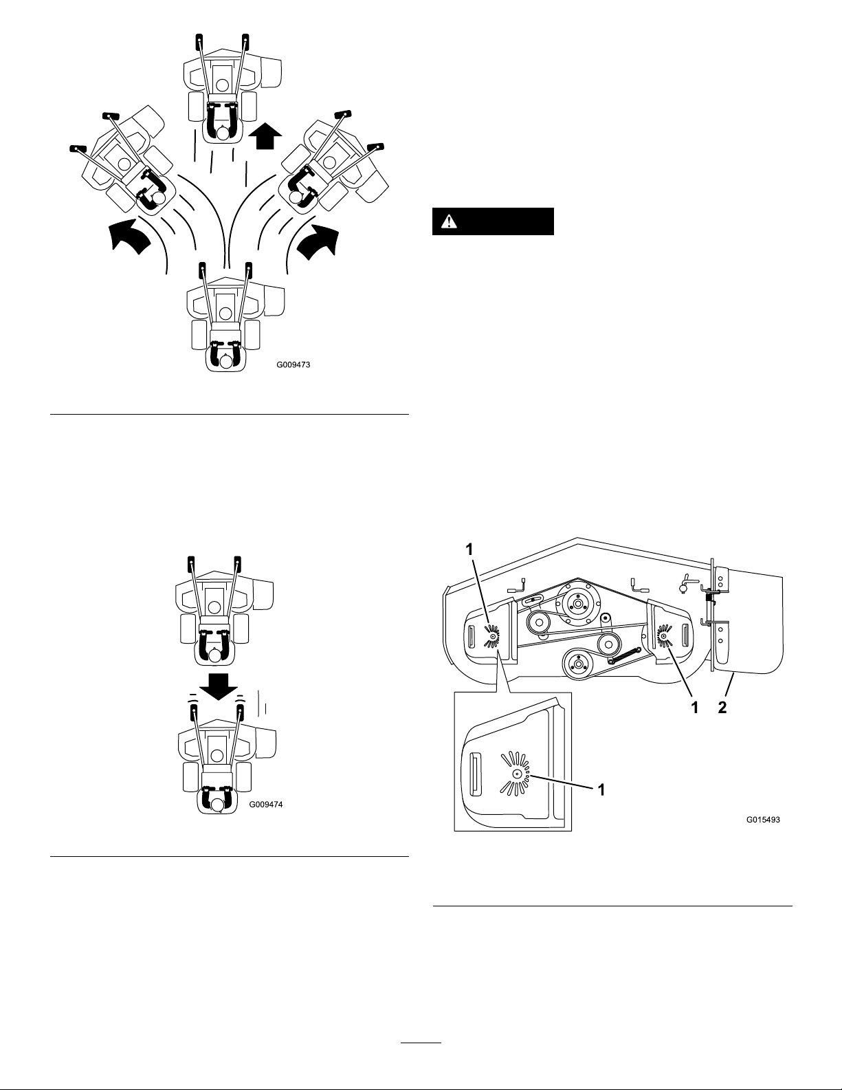
Figure22
DrivingBackward
1.Movetherightsidemotion-controllevertothecenter,
unlockedposition.
2.Slowlypullthemotion-controlleversrearward(Figure
23).
UsingtheRotationIndicator
Theslotsinthetopofthebeltcoversallowtheoperatorto
verifyifthebladeshavestoppedrotatingafterdisengagingthe
powertake-off(PTO)switch.
Disengagethepowertake-off(PTO)switch,stoptheengine,
removethekey,andwaitforallmovingpartstostopbefore
leavingtheoperatingposition.
Figure23
Figure24
1.RotationIndicator—slots
inthetopofthebeltcover
2.Side-dischargechute
24
Page 25
PushingtheMachinebyHand
G015235
TransportingtheMachine
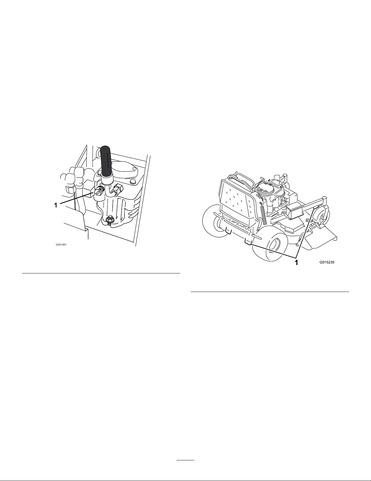
Thebypassvalvesallowthemachinetobepushedbyhand
withouttheenginerunning.
Important:Alwayspushthemachinebyhand.Donot
towthemachine,becausehydraulicdamagemayoccur.
1.DisengagethePTO,movethemotion-controlleversto
theneutral-lockedpositionandsettheparkingbrake.
2.Openthebypassvalveonbothpumpsbyturningthem
counterclockwise1to2turns.Thisallowshydraulic
uidtobypassthepumpsandthewheelstoturn
(Figure25).
Note:Rotatethebypassvalvesamaximumof2turns
sothevalvedoesnotcomeoutofthebodycausing
uidtorunout.
Useaheavy-dutytrailerortrucktotransportthemachine.
Ensurethatthetrailerortruckhasallnecessarybrakes,
lighting,andmarkingasrequiredbylaw .Pleasecarefullyread
allthesafetyinstructions.
Totransportthemachine:
1.Raisetheplatformofthemachinebeforedrivingup
ontothetrailerortruck.
2.Ifusingatrailer,connectittothetowingvehicleand
connectthesafetychains.
3.Ifapplicable,connectthetrailerbrakes.
4.Loadthemachineontothetrailerortruck.
5.Stoptheengine,removethekey ,setthebrake,and
closethefuelvalve.
6.Usethemetaltie-downloopsonthemachineto
securelyfastenthemachinetothetrailerortruckwith
straps,chains,cable,orropes(Figure26).
Figure25
1.Pump-bypassvalve
3.Releasetheparkingbrake.
4.Pushthemachinetothedesiredlocation.
5.Settheparkingbrake.
6.Closethebypassvalves,butdonotovertightenthem.
Torqueto12to15N-m(9to11ft-lb).
Important:Donotstartoroperatethemachine
withthebypassvalvesopen.Damagetosystem
mayoccur.
Figure26
1.Tractionunittie-downloop
LoadingtheMachine
Useextremecautionwhenloadingunitsontotrailersor
trucks.Onefull-widthrampthatiswideenoughtoextend
beyondthereartiresisrecommendedinsteadofindividual
rampsforeachsideoftheunit(Figure27).Theplatform
whendownandlockedintoposition,extendsbackbetween
therearwheelsandservesasastopfortippingbackward.
Havingafull-widthrampprovidesasurfacefortheplatform
tocontactiftheunitstartstotipbackward.Withtheplatform
up,afull-widthrampprovidesasurfacetowalkonbehindthe
unit.Theoperatorshoulddetermineifitisbesttohavethe
platformupordownwhenloading,dependingonconditions.
Ifitisnotpossibletouseonefull-widthramp,useenough
individualrampstosimulateafull-width,continuousramp.
Therampshouldbelongenoughsothattheanglesdonot
exceed20degrees(Figure27).Asteeperanglemaycause
mowercomponentstogetcaught,astheunitmovesfrom
ramptotrailerortruck.Steeperanglesmayalsocausethe
25
Page 26
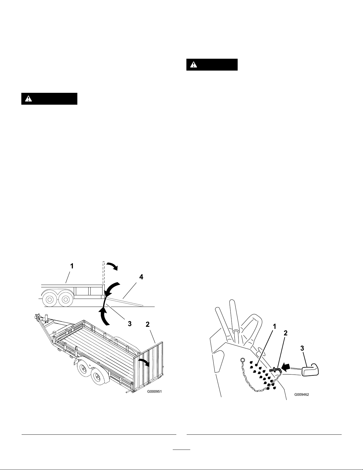
unittotipbackward.Ifloadingonornearaslope,position
thetrailerortrucksoitisonthedownsideoftheslopeand
therampextendsuptheslope.Thiswillminimizetheramp
angle.Thetrailerortruckshouldbeaslevelaspossible.
Important:Donotattempttoturntheunitwhileonthe
ramp;youmaylosecontrolanddriveofftheside.
Avoidsuddenaccelerationwhendrivinguparampand
suddendecelerationwhenbackingdownaramp.Both
maneuverscancausetheunittotipbackward.
WARNING
Loadingaunitontoatrailerortruckincreasesthe
possibilityofbackwardtip-over,andcouldcause
seriousinjuryordeath.
•Useextremecautionwhenoperatingauniton
aramp.
•Useonlyasingle,full-widthramp;donotuse
individualrampsforeachsideoftheunit.
•Ifindividualrampsmustbeused,useenough
rampstocreateanunbrokenrampsurfacewider
thantheunit.
•Donotexceeda20-degreeanglebetweenramp
andground,orbetweenaramp,atrailer,ora
truck.
•Avoidsuddenaccelerationwhiledrivingunitup
aramptoavoidtippingbackward.
•Avoidsuddendecelerationwhilebackingunit
downaramptoavoidtippingbackward.
SideDischargingorMulching theGrass
Thismowerhasahingedgrassdeectorthatdisperses
clippingstothesideanddowntowardtheturf.
DANGER
Withoutthegrassdeector,dischargecover,or
completegrasscatcherassemblymountedin
place,youandothersareexposedtobladecontact
andthrowndebris.Contactwithrotatingmower
blade(s)andthrowndebriswillcauseinjuryor
death.
•Donotremovethegrassdeectorfrom
themower,becausethegrassdeector
routesmaterialdowntowardtheturf.Ifthe
grassdeectoriseverdamaged,replaceit
immediately.
•Neverputyourhandsorfeetunderthemower.
•Nevertrytoclearthedischargeareaormower
bladesunlessyoureleasethebailandthepower
takeoff(PTO)isoff.Rotatetheignitionkeyto
theOffposition.Alsoremovethekeyandpull
thewire(s)offthesparkplug(s).
AdjustingtheHeight-of-Cut
Theheight-of-cutcanbeadjustedfrom25to127mm(1to5
inches)in6mm(1/4inches)increments.
1.Movetheheight-of-cutlevertothetransportposition
(allthewayup).
2.Selectaholeintheheight-of-cutbracketcorresponding
totheheight-of-cutdesiredand,insertthepin(Figure
28).
3.Lowertheheight-of-cutlevertothepin(Figure28).
Figure27
1.Trailer3.Notgreaterthan
2.Full-widthramp
20degrees
4.Full-widthramp(sideview)
Figure28
1.Height-of-cutholes3.Height-of-cutlever
2.Height-of-cutpin
26
Page 27
AdjustingtheFlowBafe
g012676
1 2
G012677
PositioningtheFlowBafe
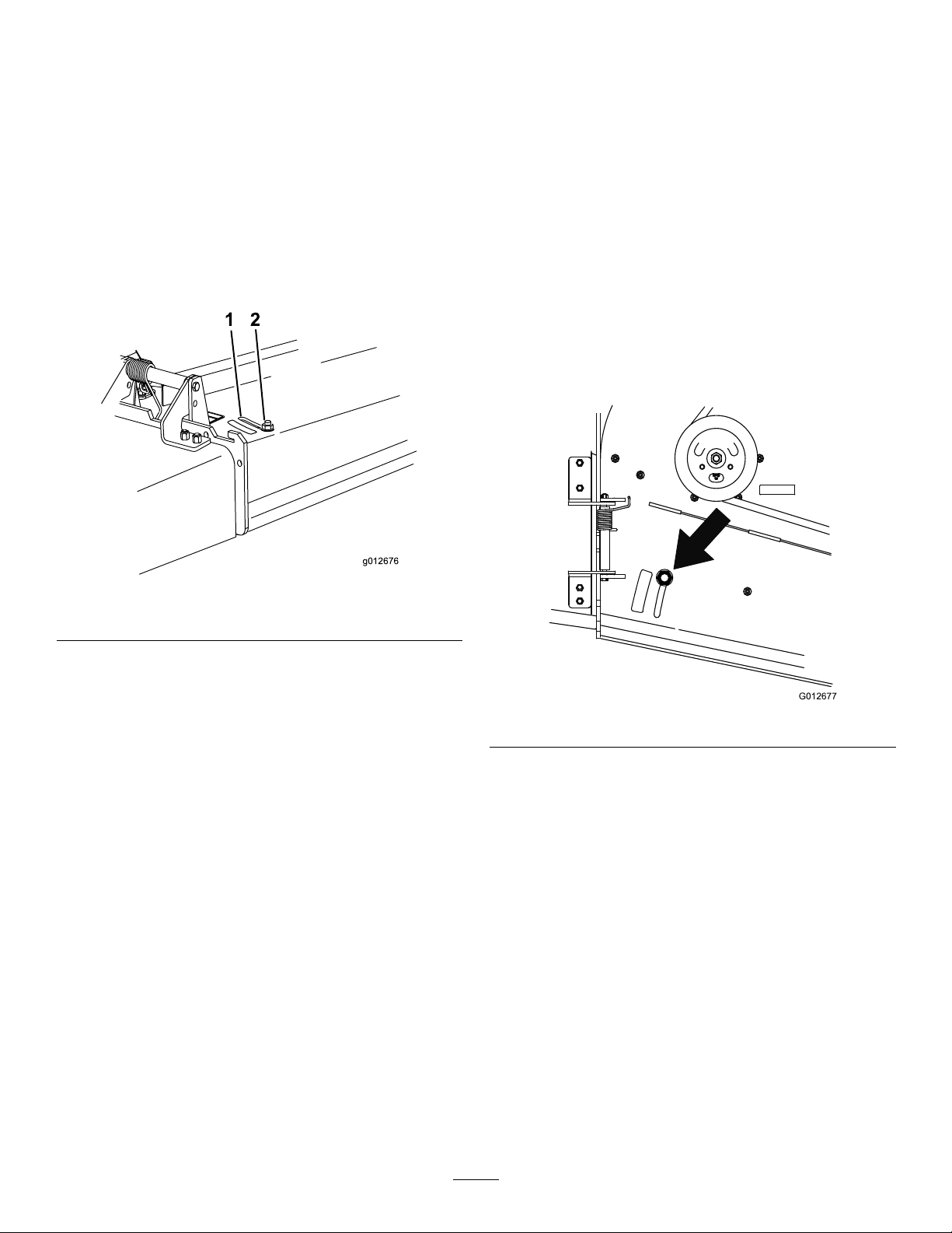
Themower-dischargeowcanbeadjustedfordifferenttypes
ofmowingconditions.Positionthecamlockandbafeto
givethebestqualityofcut.
1.DisengagethePTO,movethemotion-controlleversto
theneutral-lockedposition,andsettheparkingbrake.
2.Stoptheengine,removethekey,andwaitforallmoving
partstostopbeforeleavingtheoperatingposition.
3.Toadjustthebafe,loosenthenut(Figure29).
4.Adjustthebafeandnutintheslottothedesired
dischargeowandtightenthenut.
Thefollowingguresareonlyforrecommendeduse.
Adjustmentswillvarybygrasstype,moisturecontent,and
theheightofthegrass.
Note:Iftheenginepowerdrawsdown,andthemower
groundspeedisthesame,openupthebafe.
PositionA
Thisisthefull,rearposition(seeFigure30).Thesuggested
useforthispositionisasfollows:
•Inshort,lightgrassmowingconditions
•Indryconditions
•Smallergrassclippings
•Propelsgrassclippingsfartherawayfromthemower
Figure29
1.Slot
2.Nut
Figure30
27
Page 28
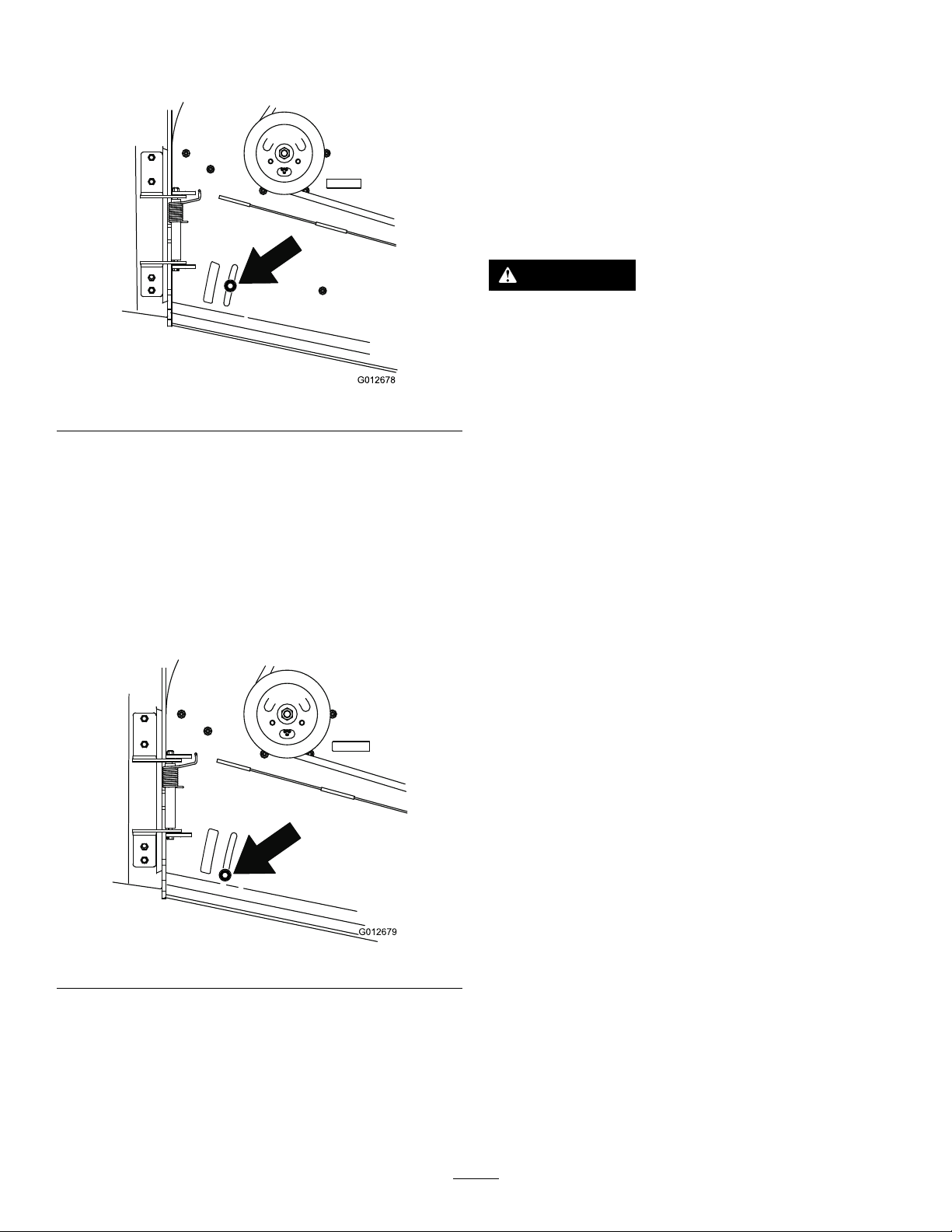
PositionB
G012678
G012679
Usethispositionwhenbagging(Figure31).
Figure31
PositionC
UsingtheMid-SizeWeight
•Weightsareinstalledtoimprovehandling,balance,and
improveperformance.Weightscanbeaddedorremoved
tocreateoptimizedperformanceunderdifferentmowing
conditionsandforoperatorpreference.
•Itisrecommendedthatweightsbeaddedorremovedone
atatimeuntilthedesiredhandingandbalanceisachieved.
Note:ContactanAuthorizedServiceDealertoordera
WeightKit.
WARNING
Excessiveweightchangescanaffectthehandling
andoperationofthemachine.Thiscouldcause
seriousinjurytoyouorbystanders.
Makeweightchangesinsmallincrementsonly.
Evaluatethemoweraftereachweightchangeto
ensurethemachinecanbeoperatedsafely.
Thisisthefull,openposition(Figure32).Thesuggesteduse
forthispositionisasfollows:
•Intall,densegrassmowingconditions
•Inwetconditions
•Lowerstheengine-powerconsumption
•Allowsincreasedgroundspeedinheavyconditions
Figure32
28
Page 29

Maintenance
Note:Determinetheleftandrightsidesofthemachinefromthenormaloperatingposition.
RecommendedMaintenanceSchedule(s)
MaintenanceService
Interval
Aftertherst8hours
Beforeeachuseordaily
Every25hours
Every50hours
Every100hours
MaintenanceProcedure
•Changetheengineoil.
•Checkthehydraulicuidlevel.
•Changethehydrauliclter.
•Checkthesafety-interlocksystem.
•Checktheengine-oillevel.
•Cleantheair-intakescreen.
•Checkthebrakes.
•Inspecttheblades.
•Cleanthemowerdeck.
•Cleanfoamair-cleanerelement.
•Greasetheliftlinkage(moreoftenindirtyordustyconditions).
•Greasethemower-deckspindles(moreoftenindirtyordustyconditions).
•Checkthepaperair-cleanerelement.
•Checkthesparkarrester(ifequipped).
•Checkthetirepressure.
•Checkthehydraulicuidlevel.
•Changetheengineoil(moreoftenindirtyordustyconditions).
•Check,cleanandgapthesparkplug.
•Checkthebattery .
•Checktheelectricclutch.
•Checkandcleantheenginecoolingnsandshrouds.
•Checkthemower-deckbelt.
•Checkthepump-drivebelt.
•Checkthehydraulichoses.
Every200hours
Every250hours
Every500hours
Every800hours
Beforestorage
Yearly
•Replacethepaperair-cleanerelement.
•Changetheengine-oillter.
•ChangethehydrauliclterandhydraulicoilwhenusingMobil®1oil.
•Adjustthecaster-pivotbearing.
•ChangethehydrauliclterandhydraulicoilwhenusingToro®HYPR-OIL™500
hydraulicoil.
•Replacethefuellter.
•Paintchippedsurfaces.
•Performallmaintenanceprocedureslistedabovebeforestorage.
•Greasethefrontcasterpivots(moreoftenindirtyordustyconditions).
•Lubricatethecaster-wheelhubs.
Important:Refertoyourengineowner’smanualforadditionalmaintenanceprocedures.
CAUTION
Ifyouleavethekeyintheignitionswitch,someonecouldaccidentlystarttheengineandseriouslyinjure
youorotherbystanders.
Removethekeyfromtheignitionanddisconnectthesparkplugwiresfromthesparkplugsbeforeyoudo
anymaintenance.Setthewiresasidesothattheydonotaccidentallycontactthesparkplugs.
29
Page 30
Premaintenance
Procedures
RaisingtheMowerforAccess
Thefrontofthemowercanberaisedandsupportedonits
backforaccessunderthemachineformaintenance.
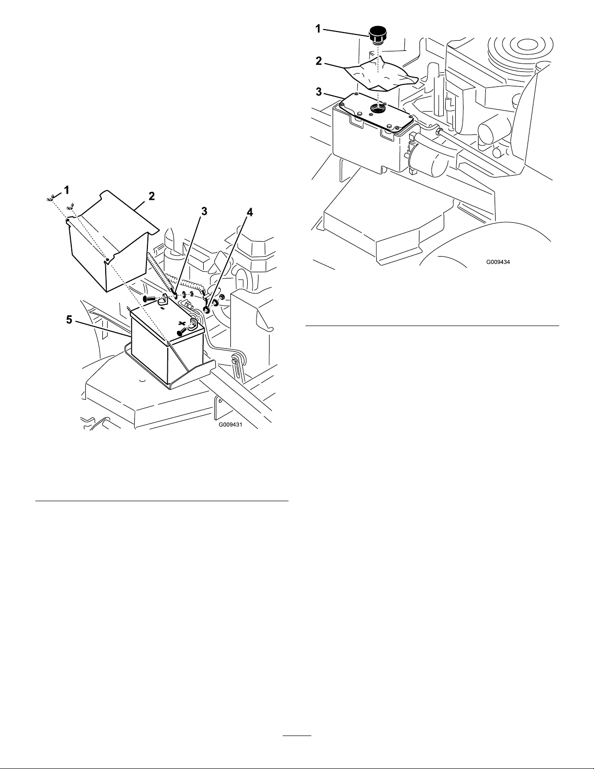
1.Raisetheplatform;refertoOperatingthePlatform
(page22).
2.Removethebattery.
Figure34
Figure33
1.Wingnut
2.Batterycover5.Battery
3.Negative-batterycable(–)
3.Drainthefuelfromthefueltank;refertoDraining
theFuelTank(page38).
4.Removethecapofthehydraulictank,andplaceapiece
ofplasticovertheopeningandinstallthehydrauliccap.
Note:Thiswillsealthehydraulictankandprevent
itfromleakingout.
4.Positive-batterycable(+)
1.Cap
2.Pieceofplastic
5.With2people,raisethefrontofthemowersothat
itrestsonthedrivetiresandtheplatformintheup
position.
6.Performanymaintenanceonthemachine.
7.With2people,lowerthefrontofthemowertothe
ground.
8.Removetheplasticunderthehydraulictankcap.
9.Installthebatteryforthemachine.
3.Hydraulictank
30
Page 31
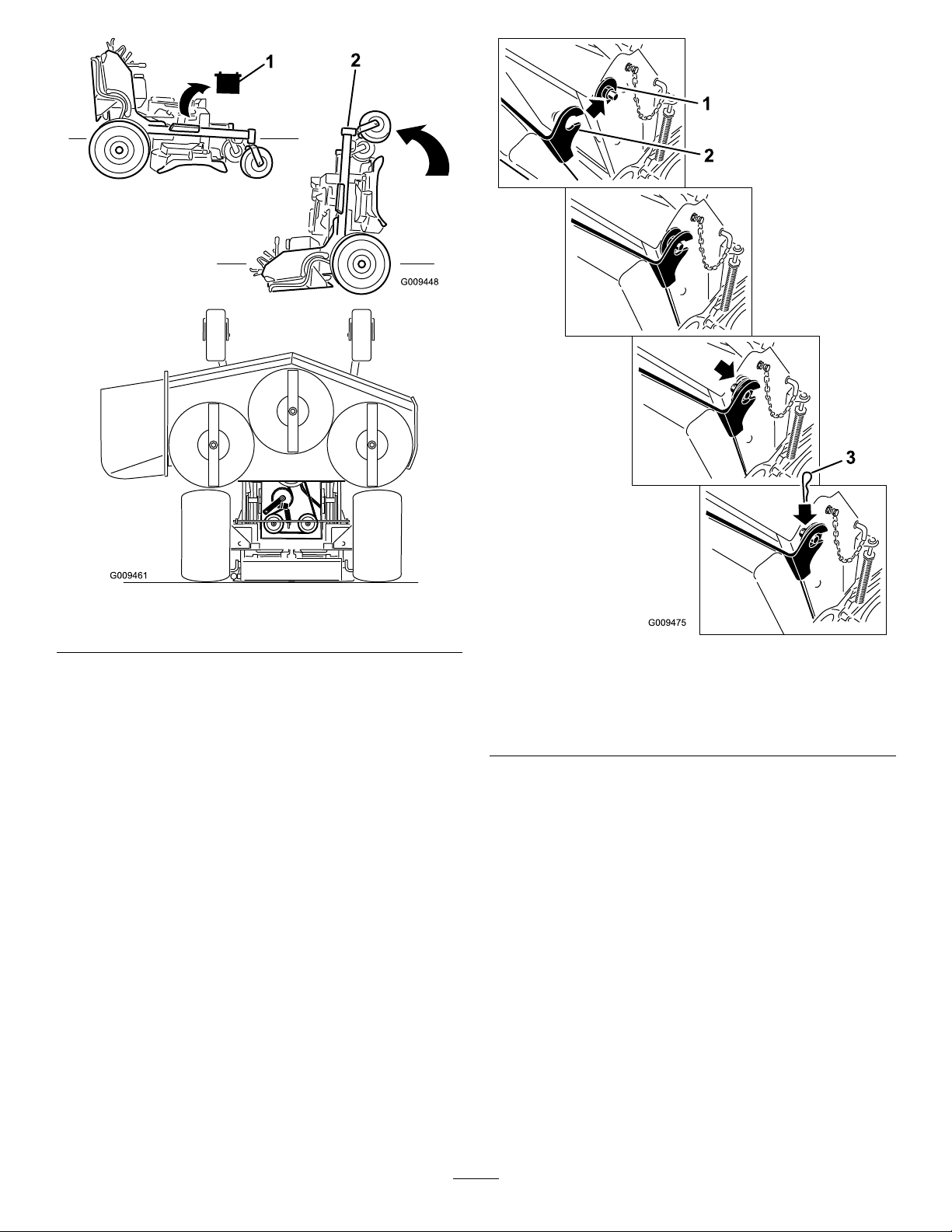
Figure35
1.Removebattery
2.Frontendofthemower
ReleasingtheCushionfor RearAccess
Youcanreleasethecushionforrearaccesstothemachinefor
maintenanceoradjustment.
1.Lowertheplatform.
2.Removethehairpin-cotterpinsoneachsideofthe
cushion.
3.Slidethelargewasherswiththeplasticbushingstothe
inside.
4.Removethecushion,andlowerittotheplatform.
5.Performanymaintenanceoradjustmentonthe
machine.
6.Raisethecushionandslideitontothepinsonboth
sidesofthemachine(Figure36).
7.Slidethelargewasherswiththeplasticbushings
intothecushionbracket,andsecurethemwitha
hairpin-cotterpin(Figure36).
1.Plasticbushingwiththe
largewasher
2.Cushionbracketwiththe
keyhole
Figure36
3.Hairpin-cotterpin
31
Page 32
Lubrication
G019356
G015236
g015589
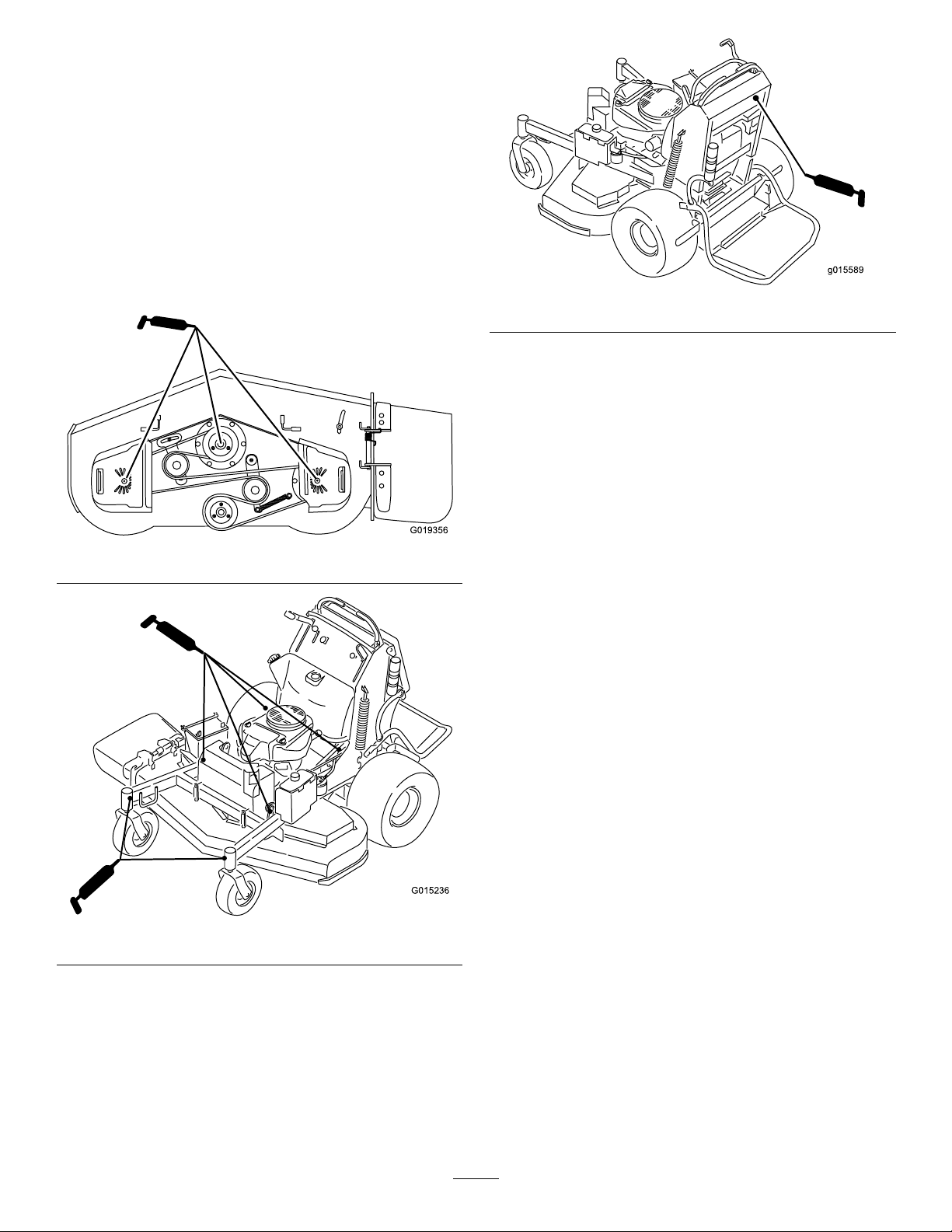
GreasewithNo.2generalpurposelithiumbaseor
molybdenumbasegrease.
LubricatingtheMachine
ServiceInterval:Every50hours—Greasetheliftlinkage
(moreoftenindirtyordustyconditions).
Every50hours—Greasethemower-deckspindles
(moreoftenindirtyordustyconditions).
Usethefollowinggraphicsforlocatingthegreasepoints.
Figure37
Figure39
GreasingtheFrontCaster Pivots
ServiceInterval:Yearly
Lubricatethefrontcasterpivotsonceayear.
1.Removethedustcapandadjustthecasterpivots;refer
toAdjustingtheCaster-PivotBearing(page43).
Note:Keepthedustcapoffuntilgreasingisdone.
2.Removethehexplug.
3.Threadagreasettingintothehole.
4.Pumpgreaseintothettinguntilitoozesoutaround
thetopbearing.
5.Removethegreasettinginthehole.Installthehex
plugandcap.
Figure38
32
Page 33
LubricatingtheCaster-Wheel Hubs
ServiceInterval:Yearly
1.Stoptheengine,waitforallmovingpartstostop,
engagetheparkingbrake,andremovethekey .
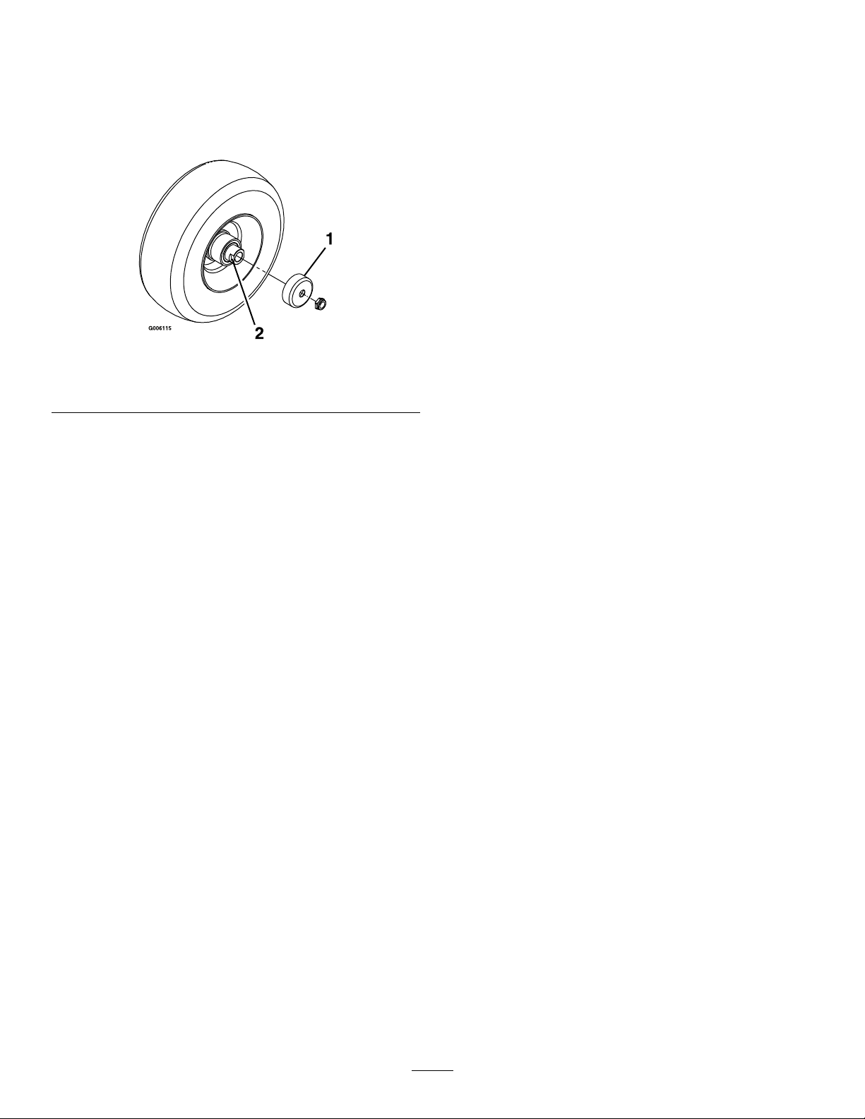
Figure40
13.Torquethenutto8to9N-m(71to80in-lb),loosen,
thentorqueitto2to3N-m(20to25in-lb).
Note:Makesureaxledoesnotextendbeyondeither
nut.
14.Installthesealguardsoverthewheelhubandinsert
wheelintocasterfork.
15.Installcasterboltandtightennutfully.
Important:Topreventsealandbearingdamage,check
thebearingadjustmentoftenbyspinningthecaster
tire.Thetireshouldnotspinfreely(morethan1or2
revolutions)orhaveanysideplay.Ifthewheelspins
freely,adjustthetorqueonthespacernutuntilthere
isaslightamountofdrag,andapplythread-locking
adhesive.
1.Sealguard2.Spacernutwithwrench
2.Removethecasterwheelfromthecasterforks.
3.Removethesealguardsfromthewheelhub.
4.Removeoneofthespacernutsfromtheaxleassembly
inthecasterwheel.
Note:Thread-lockingadhesivehasbeenappliedto
lockthespacernutstotheaxle.Removetheaxle(with
theotherspacernutstillassembledtoit)fromthe
wheelassembly.
5.Pryoutthesealsandinspectbearingsforwearor
damage,andreplaceifnecessary.
6.Packthebearingswithageneral-purposegrease.
7.Insert1bearingand1sealintothewheel.
Note:Thesealsmustbereplaced.
8.Iftheaxleassemblyhashadbothspacernutsremoved
(orbrokenloose),applyathread-lockingadhesiveto
onespacernutandthreaditontotheaxlewiththe
wrenchatsfacingoutward.
Note:DoNotthreadspacernutallofthewayonto
theendoftheaxle.Leaveapproximately3mm(1/8
inch)fromtheoutersurfaceofthespacernuttothe
endoftheaxleinsidethenut.
9.Inserttheassemblednutandaxleintothewheelonthe
sideofthewheelwiththenewsealandbearing.
10.Withtheopenendofthewheelfacingup,llthearea
insidethewheelaroundtheaxlefullofgeneral-purpose
grease.
11.Insertthesecondbearingandthenewsealintothe
wheel.
12.Applyathread-lockingadhesivetothesecondspacer
nut,andthreaditontotheaxlewiththewrenchats
facingoutward.
ats
33
Page 34
EngineMaintenance
ServicingtheAirCleaner
ServiceInterval/Specication
Inspectthefoamandpaperelements,andreplacethemif
theyaredamagedorexcessivelydirty.
CleaningtheFoamAir-CleanerElement
ServiceInterval:Every25hours
1.Washthefoamelementinliquidsoapandwarmwater.
Whentheelementisclean,rinseitthoroughly.
2.Drytheelementbysqueezingitinacleancloth.
Important:Replacethefoamelementifitistorn
orworn.
Note:Servicetheaircleanermorefrequently(everyfew
operatinghours)iftheoperatingconditionsareextremely
dustyorsandy .
Important:Donotapplyoiltothefoamorpaper
element.
RemovingtheFoamandPaper
Elements
1.DisengagethePTOandsettheparkingbrake.
2.Stoptheengine,removethekey,andwaitforallmoving
partstostopbeforeleavingtheoperatingposition.
3.Cleanaroundtheaircleanertopreventdirtfrom
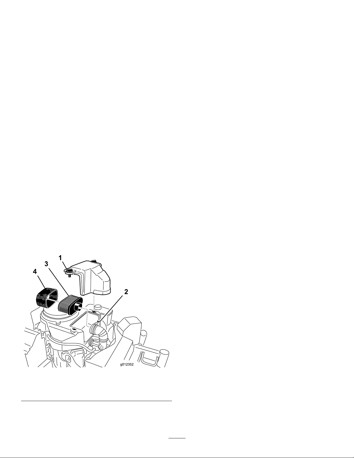
gettingintotheengineandcausingdamage(Figure41).
4.Unscrewthecoverknobsandremovetheair-cleaner
cover(Figure41).
5.Unscrewthehoseclampandremovetheair-cleaner
assembly(Figure41).
6.Carefullypullthefoamelementoffthepaperelement
(Figure41).
ServicingthePaperAir-Cleaner
Element
ServiceInterval:Every50hours—Checkthepaper
air-cleanerelement.
Every200hours—Replacethepaperair-cleaner
element.
1.Inspecttheelementfortears,anoilylm,ordamageto
therubberseal.
2.Replacethepaperelementifitisdamaged(Figure41).
InstallingtheFoamandPaperElements
Important:T opreventenginedamage,alwaysoperate
theenginewiththecompletefoamandpaperair-cleaner
assemblyinstalled.
1.Carefullyslidethefoamelementontothepaper
air-cleanerelement(Figure41).
2.Placetheair-cleanerassemblyontotheair-cleanerbase
orhoseandsecureit(Figure41).
3.Placetheair-cleanercoverintopositionandtighten
thecoverknob(Figure41).
Figure41
1.Cover
2.Hoseclamp4.Foamelement
3.Paperelement
ServicingtheEngineOil
ServiceInterval:Beforeeachuseordaily—Checkthe
engine-oillevel.
Aftertherst8hours—Changetheengineoil.
Every100hours—Changetheengineoil(moreoften
indirtyordustyconditions).
Every200hours—Changetheengine-oillter.
Note:Changetheoilmorefrequentlywhentheoperating
conditionsareextremelydustyorsandy .
Note:Therearedifferentoilcapacitiesforthedifferent
modelslistedinthismanual.Ensurethecorrectamountof
oilisused.
Important:Remembertoadd80%oftheoilandthen
graduallyllittothefullmarkonthedipstick.
OilType:Detergentoil(APIserviceSF,SG,SH,SJorSL)
CrankcaseCapacity:1.7L(58oz)withthelterremoved;
1.5L(51oz)withoutthelterremoved
Viscosity:Refertothetablebelow:
34
Page 35
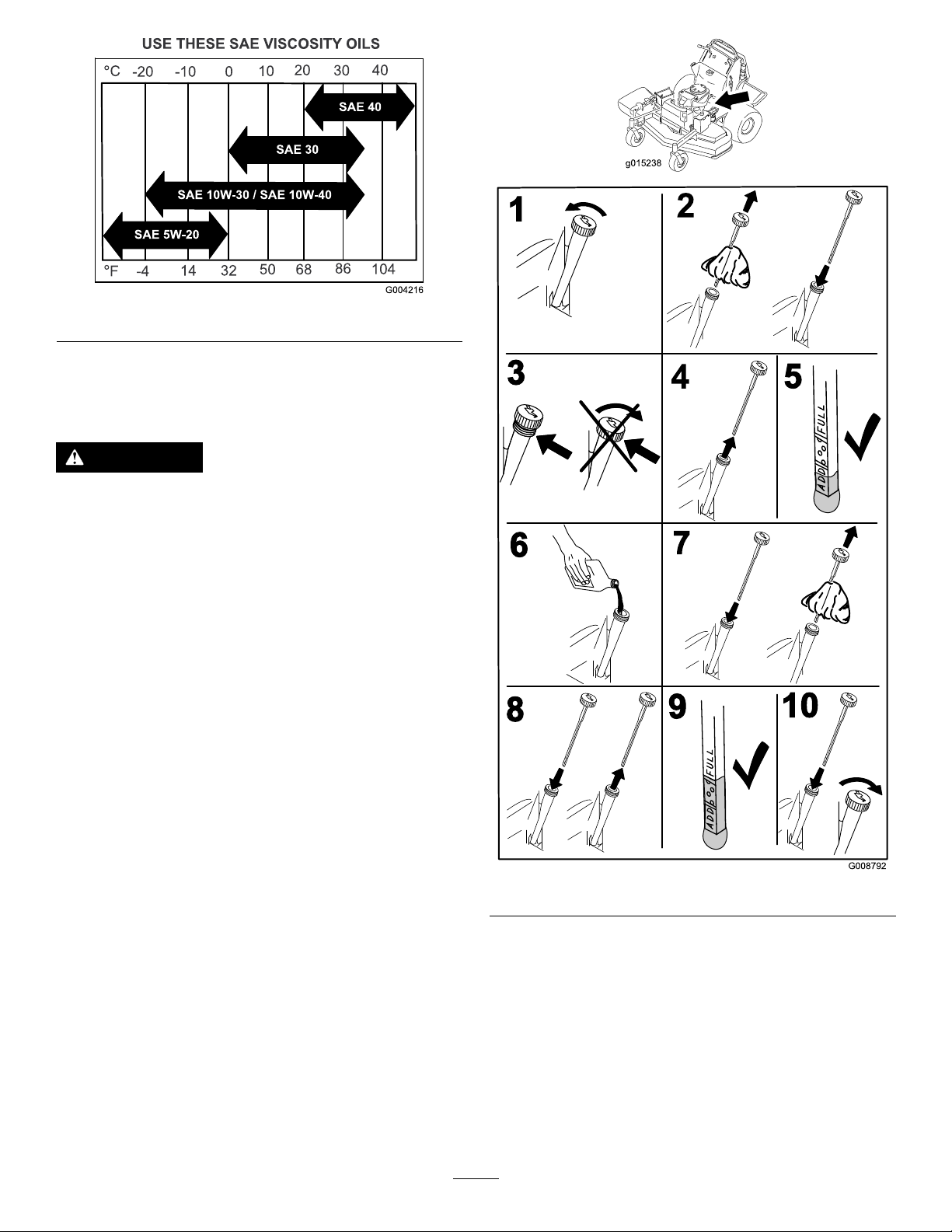
Figure42
g015238
G008792
1
2
5
6
7
3
9
10
4
8
CheckingtheEngine-OilLevel
Note:Checktheoilwhentheengineiscold.
WARNING
Contactwithhotsurfacesmaycausepersonal
injury.
Keephands,feet,face,clothingandotherbody
partsawaythemuferandotherhotsurfaces.
Important:Donotoverllthecrankcasewithoil,
becausedamagetotheenginemayresult.Donotrun
enginewithoilbelowtheLowmark,becausetheengine
maybedamaged.
1.DisengagethePTO,movethemotion-controlleversto
theneutral-lockedposition,andsettheparkingbrake.
2.Stoptheengine,removethekey ,andwaitforall
movingpartstostopbeforeleavingtheoperating
position(Figure43).
Figure43
35
Page 36
ChangingtheEngineOil
G008796
2
3
4
5
6
1
Note:Disposeoftheusedoilatarecyclingcenter.
1.Parkthemachinesothatthedrainsideisslightly
lowerthantheoppositesidetoassuretheoildrains
completely.
2.DisengagethePTO,movethemotion-controlleversto
theneutral-lockedposition,andsettheparkingbrake.
3.Stoptheengine,removethekey,andwaitforallmoving
partstostopbeforeleavingtheoperatingposition.
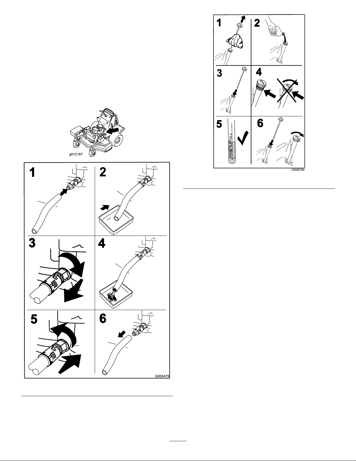
4.ChangetheengineoilasshowninFigure44.
Figure45
6.Starttheengineanddrivetoaatarea.
7.Checktheengineoillevel.
ChangingtheEngine-OilFilter
Note:Changetheengine-oilltermorefrequentlywhen
operatingconditionsareextremelydustyorsandy.
1.Draintheoilfromtheengine;refertoChangingthe
EngineOil(page36).
2.Placearagundertheoilltertosoakupanyspilledoil.
Important:Spilledoilmaydrainundertheengine
andontotheclutch.Oilspilledontheclutchmay
damagetheclutch,causethebladestostopslowly
whentheclutchisintheOffposition,andcause
theclutchtoslipwhentheclutchisswitchedto
theOnposition.Wipeupanyspilledoil.
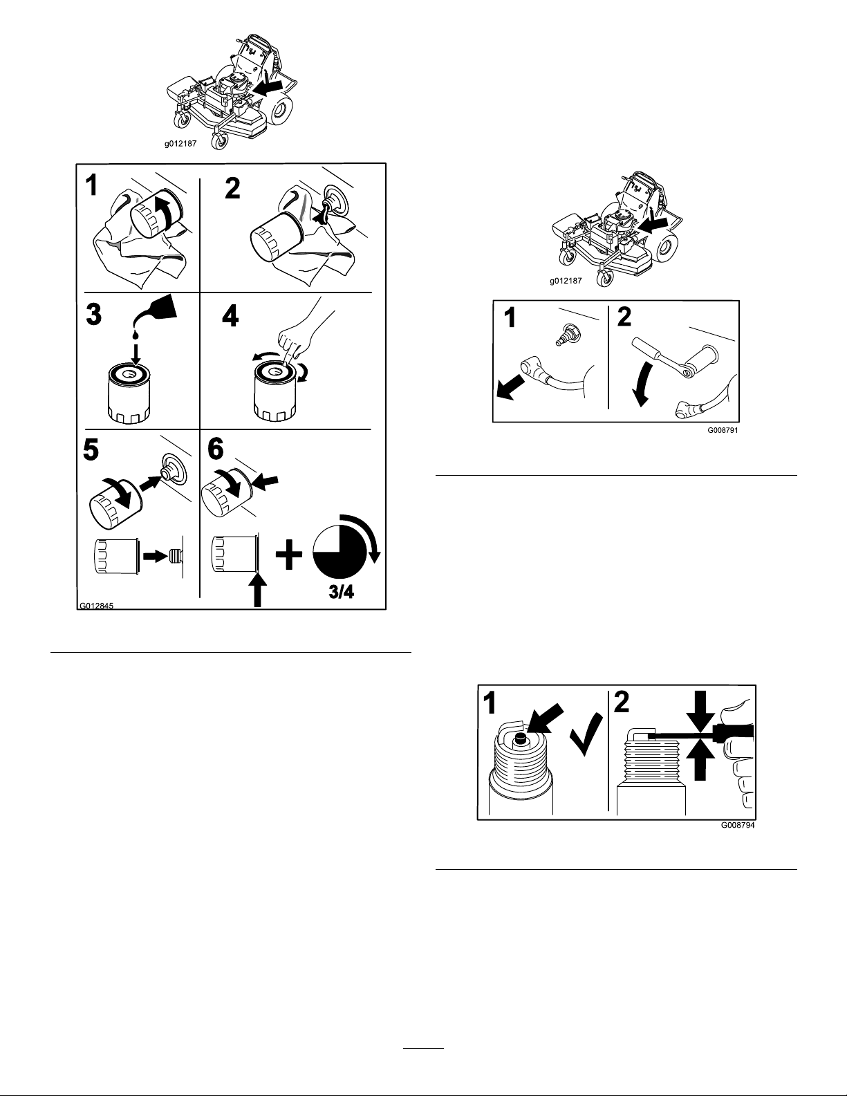
3.Changetheengine-oillter(Figure46).
Figure44
5.Slowlypourapproximately80%ofthespeciedoil
intothellertube,andslowlyaddtheadditionaloilto
bringittotheFullmark(Figure45).
36
Page 37
G012845
3/4
2
3
4
5
6
1
RemovingtheSparkPlug
G008794
1
2
1.DisengagethePTO,movethemotion-controlleversto
theneutral-lockedposition,andsettheparkingbrake.
2.Stoptheengine,removethekey,andwaitforallmoving
partstostopbeforeleavingtheoperatingposition.
3.RemovethesparkplugasshowninFigure47.
Figure46
Note:Ensuretheoil-ltergaskettouchestheengine,
andthenanextra3/4turniscompleted.
4.Fillthecrankcasewiththepropertypeofnewoil;refer
toChangingtheEngineOil(page36).
ServicingtheSparkPlug
ServiceInterval:Every100hours
Makesuretheairgapbetweenthecenterandsideelectrodes
iscorrectbeforeinstallingthesparkplug.
Figure47
CheckingtheSparkPlug
Important:Donotcleanthesparkplug(s).Always
replacethesparkplug(s)whenithasablackcoating,
wornelectrodes,anoilylm,orcracks.
Ifyouseelightbrownorgrayontheinsulator,theengineis
operatingproperly .Ablackcoatingontheinsulatorusually
meanstheaircleanerisdirty.
Setthegapto0.75mm(0.03inch).
Figure48
Useasparkplugwrenchforremovingandinstallingthespark
plug(s)andagappingtool/feelergaugetocheckandadjust
theairgap.Installanewsparkplug(s)ifnecessary.
TypeforallEngines:NGK
AirGap:0.75mm(0.03inch)
®
BPR4ESorequivalent
37
Page 38
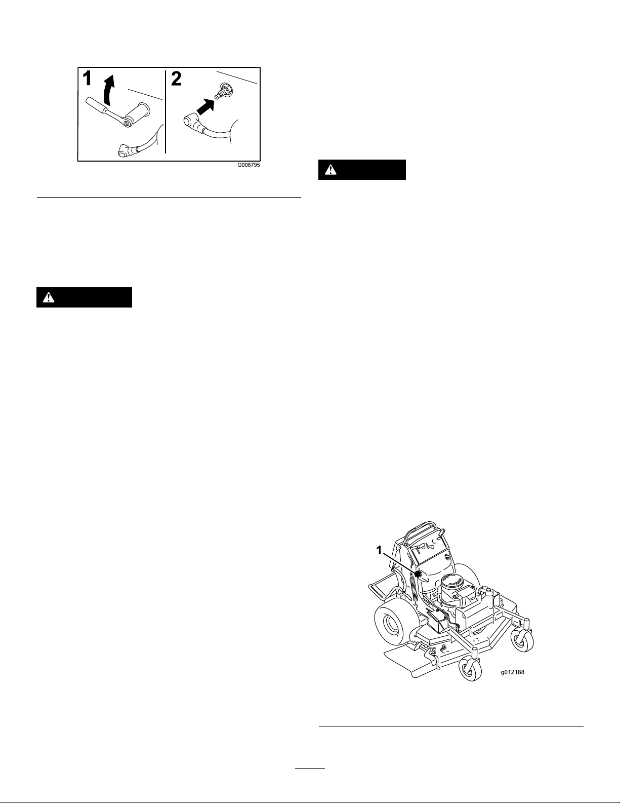
InstallingtheSparkPlug
Tightenthesparkplug(s)to22N-m(16ft-lb).
FuelSystem
Maintenance
DrainingtheFuelTank
Note:Thereisnootherrecommendedwaytodrainfuel
fromthetank,otherthanusingasyphonpump.Asyphon
pumpcanbepurchasedatahardwarestore.
Figure49
CheckingtheSparkArrester (ifequipped)
ServiceInterval:Every50hours
WARNING
Hotexhaust-systemcomponentsmayignite
gasolinevaporsevenaftertheengineisstopped.
Hotparticlesexhaustedduringengineoperation
mayigniteammablematerials.Firemayresultin
personalinjuryorpropertydamage.
Donotrefuelorruntheengineunlessthespark
arresterisinstalled.
1.Stoptheengine,waitforallmovingpartstostop,
engagetheparkingbrake,andremovethekey .
2.Waitforthemufertocool.
3.Ifanybreaksinthescreenorweldsareobserved,
replacethearrester.
4.Ifpluggingofthescreenisobserved,removethe
arrester,shakelooseparticlesoutofthearrester,and
cleanthescreenwithawirebrush(soakinsolventif
necessary).
DANGER
Incertainconditions,gasolineisextremely
ammableandhighlyexplosive.Areorexplosion
fromgasolinecanburnyouandothersandcan
damageproperty.
•Draingasolinefromthefueltankwhenthe
engineiscold.Dothisoutdoorsinanopenarea.
Wipeupanygasolinethatspills.
•Neversmokewhendraininggasoline,andstay
awayfromanopename,orwhereasparkmay
ignitethegasolinefumes.
1.DisengagethePTO,movethemotion-controlleversto
theneutral-lockedposition,andsettheparkingbrake.
2.Stoptheengine,removethekey,andwaitforallmoving
partstostopbeforeleavingtheoperatingposition
3.Cleanaroundthefuelcaptopreventdebrisfrom
gettingintothefueltank(Figure51).
4.Removethefuelcap.
5.Insertasyphonpumpintothefueltank.
6.Usingthesyphonpump,drainthefuelintoacleangas
can(Figure50).
7.Wipeupanyspilledfuel.
5.Installarresteronexhaustoutlet.
Figure50
1.Fuelcap
38
Page 39
ServicingtheFuelFilter
ElectricalSystem
ReplacingtheFuelFilter
ServiceInterval:Every800hours/Y early(whichevercomes
rst)
Donotinstalladirtylterifitisremovedfromthefuelline.
Note:Wipeupanyspilledfuel.
1.DisengagethePTOandsettheparkingbrake.
2.Stoptheengine,removethekey,andwaitforallmoving
partstostopbeforeleavingtheoperatingposition.
3.Closethefuelshut-offvalve(behindtheoperator
cushion).
4.Squeezetheendsofthehoseclampstogetherandslide
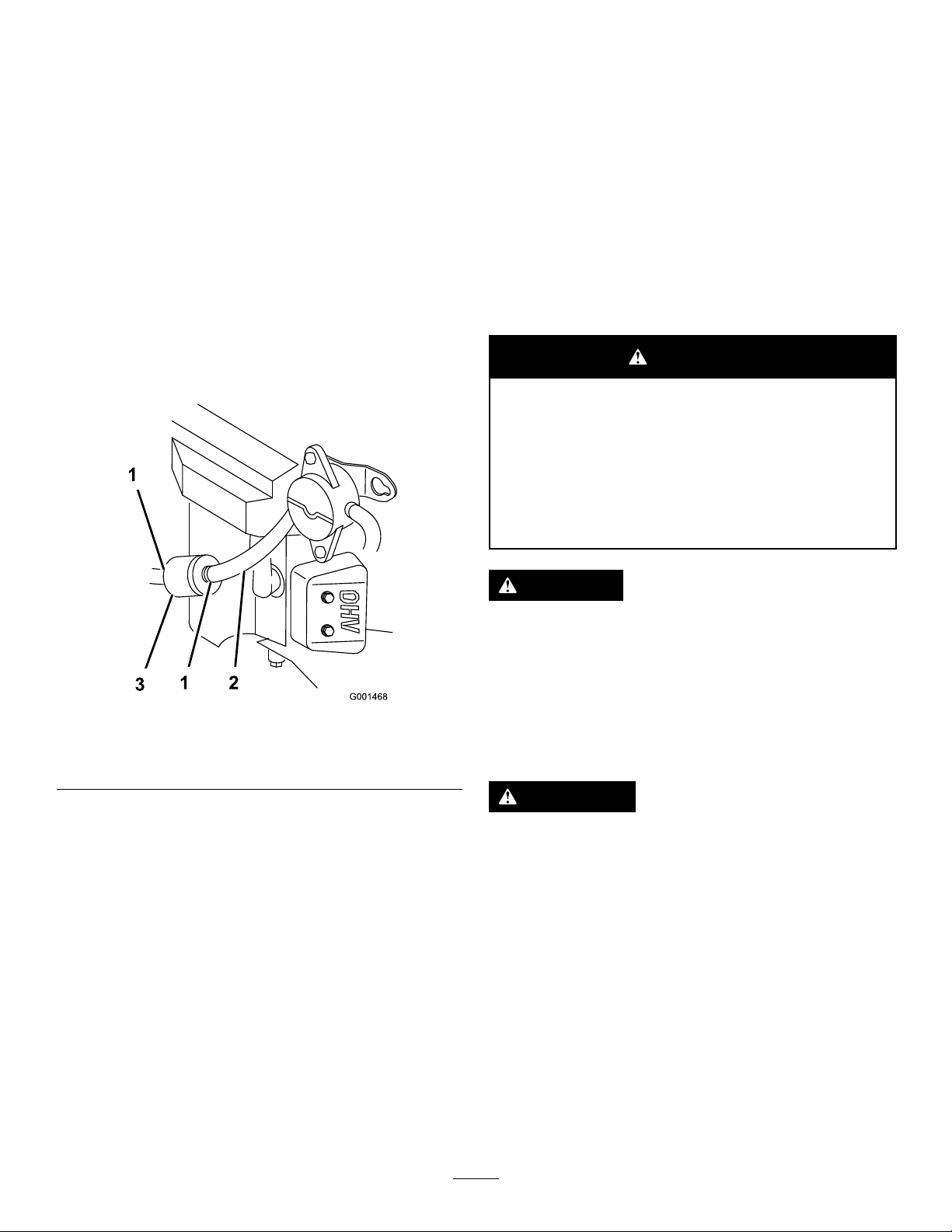
themawayfromthelter(Figure51).
Maintenance
ServicingtheBattery
ServiceInterval:Every100hours
Alwayskeepthebatterycleanandfullycharged.Useapaper
toweltocleanthebatterycase.Ifthebatteryterminalsare
corroded,cleanthemwithasolutionoffourpartswaterand
onepartbakingsoda.Applyalightcoatingofgreasetothe
batteryterminalstopreventcorrosion.
Voltage:12V
WARNING
CALIFORNIA
Proposition65Warning
Batteryposts,terminals,andrelated
accessoriescontainleadandleadcompounds,
chemicalsknowntotheStateofCalifornia
tocausecancerandreproductiveharm.
Washhandsafterhandling.
Figure51
1.Hoseclamp3.Filter
2.Fuelline
5.Removethelterfromthefuellines.
6.Installanewlterandmovethehoseclampscloseto
thelter.
7.Openthefuelshut-offvalve.
8.Checkforfuelleaksandrepairifneeded.
9.Wipeupanyspilledfuel.
DANGER
Donotdrinkelectrolyte,andavoidcontactwith
skin,eyesorclothing.Wearsafetyglassestoshield
youreyesandrubberglovestoprotectyourhands.
Batteryelectrolytecontainssulfuricacidwhichisa
deadlypoisonandcausessevereburns.
RemovingtheBattery
WARNING
Batteryterminalsormetaltoolscouldshortagainst
metalmachinecomponentscausingsparks.Sparks
cancausethebatterygassestoexplode,resulting
inpersonalinjury.
•Whenremovingorinstallingthebattery,donot
allowthebatteryterminalstotouchanymetal
partsofthemachine.
•Donotallowmetaltoolstoshortbetween
thebatteryterminalsandmetalpartsofthe
machine.
39
Page 40
WARNING
Incorrectbattery-cableroutingcoulddamagethe
machineandcablescausingsparks.Sparkscan
causethebatterygassestoexplode,resultingin
personalinjury.
•Alwaysdisconnectthenegative(black)battery
cablebeforedisconnectingthepositive(red)
cable.
•Alwaysconnectthepositive(red)batterycable
beforeconnectingthenegative(black)cable.
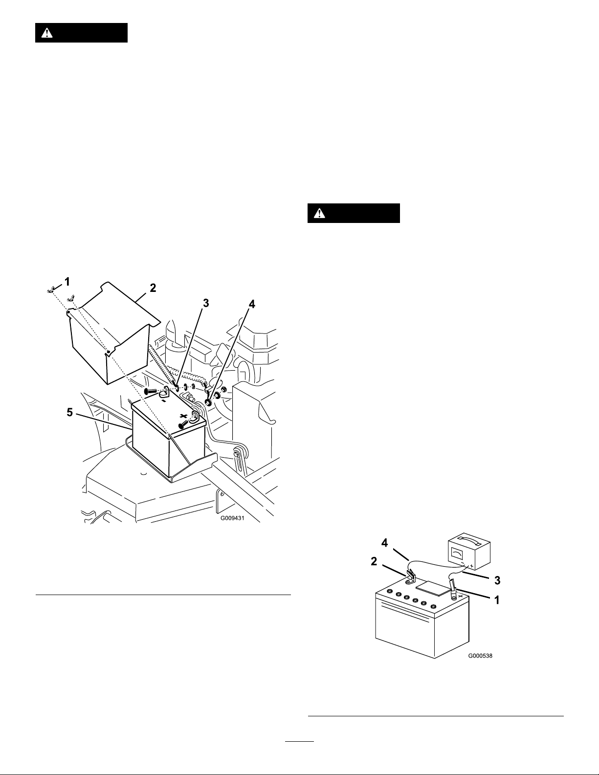
2.Securethebatterywiththeholddownplate,j-bolts,
andlocknuts.
3.Installthepositive(red)batterycabletopositive(+)
batteryterminalwithanut,awasher,andabolt(Figure
52).
4.Slidetherubbercoveroverthepost.
5.Installthenegativebatterycableandthegroundwire
tothenegative(-)batteryterminalwithanut,awasher,
andabolt(Figure52).
6.Slidetherubbercoveroverthepost.
1.DisengagethePTOandsettheparkingbrake.
2.Stoptheengine,removethekey,andwaitforallmoving
partstostopbeforeleavingtheoperatingposition.
3.Lifttheblack,rubbercoveronthenegativecable.
4.Disconnectthenegativebatterycablefromthenegative
(-)batteryterminal(Figure52).
ChargingtheBattery
WARNING
Chargingthebatteryproducesgassesthatcan
explode.
Neversmokenearthebatteryandkeepsparksand
amesawayfrombattery.
Important:Alwayskeepthebatteryfullycharged
(1.265specicgravity)topreventbatterydamagewhen
thetemperatureisbelow32°F(0°C).
1.Removethebatteryfromthechassis;refertoRemoving
theBattery(page39).
2.Checktheelectrolytelevel.
3.Ensurethatthellercapsareinstalledonthebattery.
4.Chargethebatteryfor1hourat25to30ampsor6
hoursat4to6amps.
5.Whenthebatteryisfullycharged,unplugthecharger
fromtheelectricaloutlet,anddisconnectthecharger
leadsfromthebatteryposts(Figure53).
Figure52
1.Wingnut4.Positivebatterycable
2.Batterycover5.Battery
3.Negativebatterycable
5.Slidetheredterminalbootoffthepositive(red)battery
terminal.
6.Removethepositive(red)batterycable(Figure52).
7.Removethebatteryholddownplate(Figure52),and
removethebattery.
InstallingtheBattery
1.Placethebatteryontothemachine(Figure52).
6.Installthebatteryontothemachineandconnectthe
batterycables;refertoInstallingtheBattery(page40).
Note:Donotrunthemachinewiththebattery
disconnected;electricaldamagemayoccur.
Figure53
1.PositiveBatteryPost
2.NegativeBatteryPost
40
3.Red(+)ChargerLead
4.Black(-)ChargerLead
Page 41
ServicingtheFuses
g015401
1
g015241
DriveSystem
Theelectricalsystemisprotectedbyfuses,andrequiresno
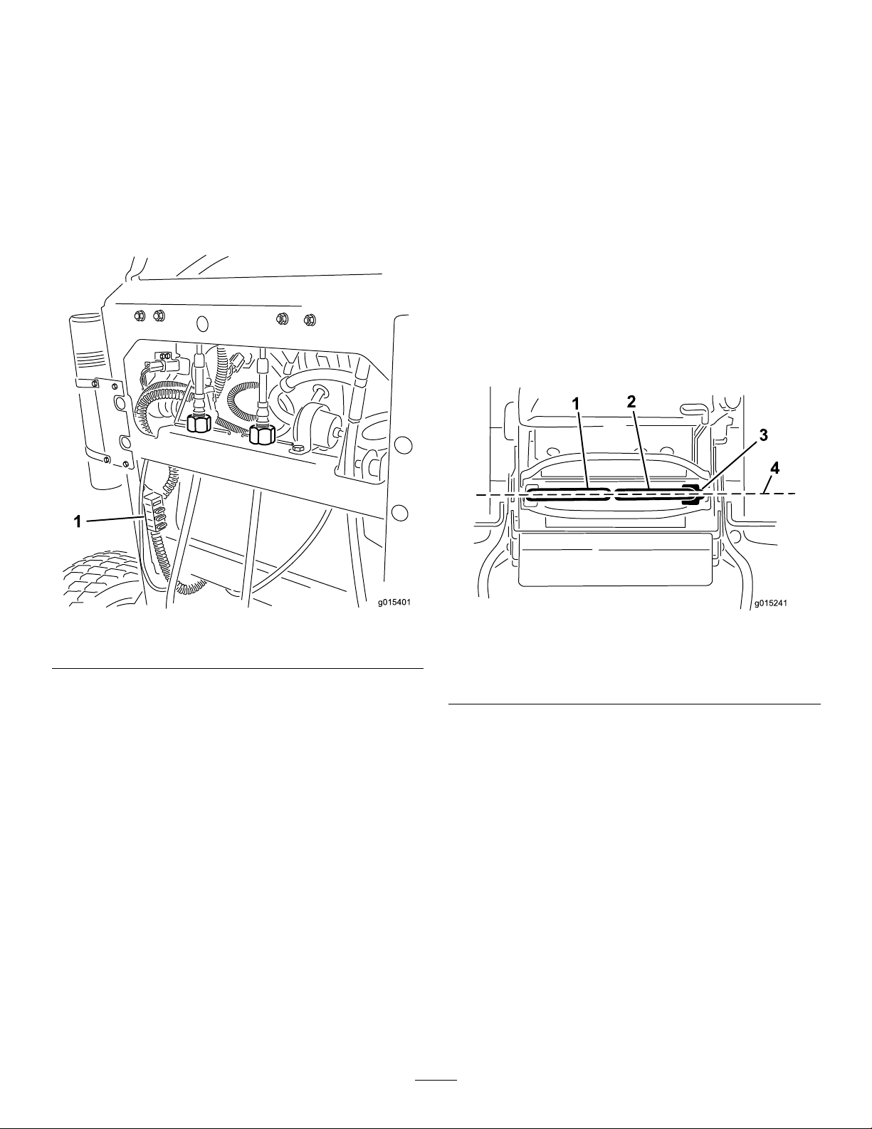
maintenance.Ifafuseblows,checkthecomponentorcircuit
foramalfunctionorshort.
1.Releasethecushionfromtherearofthemachine.
2.Pulloutonthefusetoremoveorreplaceit(Figure54).
3.Installthecushiontotherearofthemachine.
Note:Ensurethatthecorrect-sizefuseisinstalled
Figure54.
Maintenance
AdjustingtheTracking
Note:Determinetheleftandrightsidesofthemachine
fromthenormaloperatingposition.
1.Pushbothcontrolleversforwardthesamedistance.
2.Checkifthemachinepullstooneside.
Note:Ifitdoes,stopthemachineandsettheparking
brake.
3.Releasethecushionfromtherearofthemachine.
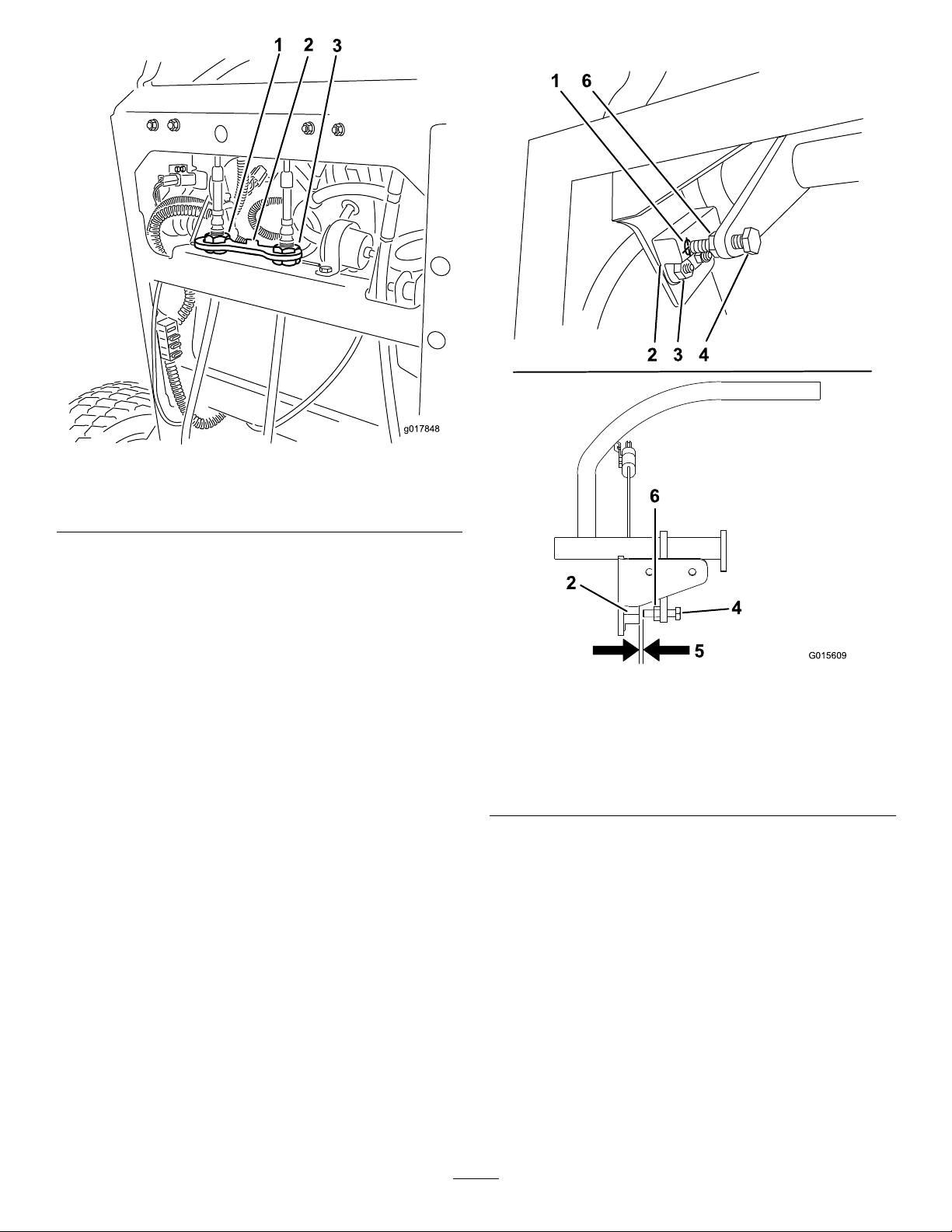
4.Rotatetherightcableadjustmenttopositiontheright
motioncontrolinthecenterofthecontrolpanel
neutral-lockslot(Figure56).
Figure54
1.Fuses
1.Leftmotion-controllever
2.Rightmotion-controllever4.Alignthecontrollevers
5.Rotatetheleftcableadjustmenttomatchtheleft
wheelspeedtothepreviouslysetrightwheelspeed.
6.Adjustinquarter-turnincrementsuntilthemachine
tracksstraight.
Note:Onlyadjusttheleftcabletomatchtheleft
wheelspeedtotherightwheelspeed.Donotadjust
therightwheelspeedasthiswillpositiontheright
motion-controlleveroutofthecenterforthecontrol
panelneutral-lockslot.
Figure55
3.Neutral-lockedposition
fronttoback
41
Page 42
3
g017848
Figure56
G015609
1 6
2 3 4
4
2
5
6
6.Testthesafety-interlocksystembeforeoperation.
1.Leftcableadjustment
2.Cablelock
3.Rightcableadjustment
7.Checkforpropertracking.
Note:Ifthemachinewillnotstartafteradjusting
thetracking,makesureproximityswitchtargetaligns
withboltattachedtomotion-controllever;referto
AdjustingtheProximitySwitch(page42).
8.Repeatthecableadjustmentuntilthetrackingis
correct.
9.Checkthatthemachinedoesnotcreepfromneutral
withtheparkbrakesdisengaged.
Important:Donotrotatethelinkagetoofar,asthis
maycausethemachinetocreepinneutral.
AdjustingtheProximitySwitch
Usethisprocedureifthemachinewillnotstartafteradjusting
thetracking.
1.Ensurethattheboltattachedtothemotion-control
leveralignswiththeproximityswitchtarget(Figure57).
Figure57
1.Proximityswitchtarget4.Boltattachedtothe
motion-controllever
2.Proximityswitch5.Distancebetween0.51
to1.02mm(0.02to0.04
inches)isneeded
3.Boltsandnuts6.Jamnut
2.Ifneeded,loosentheboltsandadjusttheproximity
switchuntilthetargetalignswiththeboltattachedto
themotion-controllever(Figure57).
3.Checkthedistanceofthebolttotheproximityswitch;
itneedstobebetween0.51to1.02mm(0.02to0.04
inches)asshowninFigure57.
4.Ifadjustmentisneeded,loosenthejamnutandadjust
thebolttothecorrectdistance.
5.Tightenthejamnutafteradjustingthebolt(Figure57).
42
Page 43
CheckingtheTirePressure
ServiceInterval:Every50hours/Monthly(whichever
comesrst)
Maintaintheairpressureinthereartiresat83to97kPa(12
to14psi).
Important:Uneventirepressurecancauseanuneven
cut.
Note:Thefronttiresaresemi-pneumatictiresanddonot
requireair-pressuremaintenance.
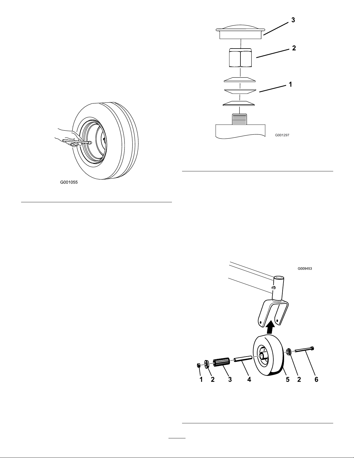
Figure59
Figure58
AdjustingtheCaster-Pivot Bearing
ServiceInterval:Every500hours/Y early(whichevercomes
rst)
1.Disengagetheblade-controlswitch(PTO),movethe
motioncontrolleverstotheneutral-lockedposition,
andsettheparkingbrake.
2.Stoptheengine,removethekey,andwaitforallmoving
partstostopbeforeleavingtheoperatingposition.
3.Removethedustcapfromthecasterandtightenthe
locknut(Figure59).
4.Tightenthelocknutuntilthespringwashersareat,
andthenbackoffa1/4turntoproperlysetthepreload
onthebearings(Figure59).
1.Springwashers
2.Locknut
3.Dustcap
ServicingtheCasterWheels andBearings
Thecasterwheelsrotateonarollerbearingsupportedbya
spannerbushing.Ifthebearingiskeptwelllubricated,wear
willbeminimal.Failuretokeepthebearingwelllubricated
willcauserapidwear.Awobblycasterwheelusuallyindicates
awornbearing.
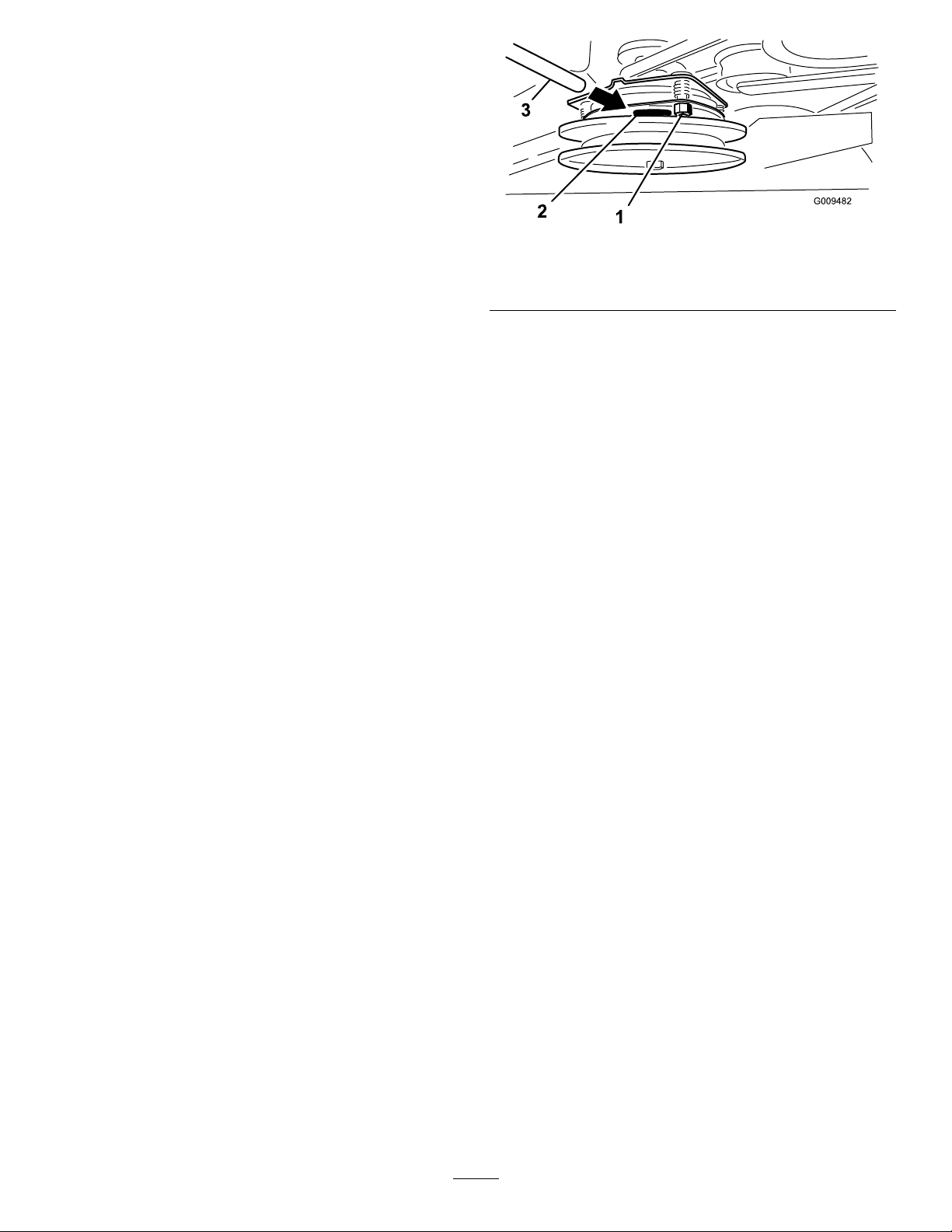
1.Removethelocknutandwheelboltholdingthecaster
wheeltothecasterfork(Figure60).
Important:Makesurespringwashersare
installedcorrectlyasshowninFigure59.
5.Installthedustcap(Figure59).
1.Locknut
2.Wheelbolt5.Rollerbearing
3.Bushing
43
Figure60
4.Spannerbushing
Page 44
2.Removeonebushing,thenpullthespannerbushing
androllerbearingoutofthewheelhub(Figure60).
3.Removetheotherbushingfromthewheelhub,and
cleananygreaseanddirtfromthewheelhub(Figure
60).
4.Inspecttherollerbearing,bushings,spannerbushing
andtheinsideofthewheelhubforwear.
Note:Replaceanydefectiveorwornparts(Figure60).
5.Placeonebushingintothewheelhub(Figure60).
6.Greasetherollerbearingandspannerbushing,and
slidethemintothewheelhub(Figure60).
7.Placethesecondbushingintothewheelhub(Figure
60).
8.Installthecasterwheelintothecasterforkandsecure
itwiththewheelboltandlocknut(Figure60).
9.Tightenthelocknutuntilthespannerbushingbottoms
againsttheinsideofthecasterforks(Figure60).
10.Greasethettingonthecasterwheel.
Figure61
1.Adjustingnut3.Feelergauge
2.Slot
AdjustingtheElectricClutch
ServiceInterval:Every100hours—Checktheelectric
clutch.
Theclutchisadjustabletoensureproperengagementand
properbraking.
1.Inserta0.4to0.5mm(0.01to0.02inches)feelergauge
throughoneinspectionslotinthesideoftheassembly .
Note:Makesureitisbetweenthearmatureandthe
rotorfrictionsurfaces.
Note:Thegapneedstobeatleast0.4mm(0.02
inches)andnotmorethan0.5mm(0.02inches).
2.Ifadjustmentisneeded,usea0.4mm(0.02inches)
feelergaugetoseteachofthe3adjustment-slot
positions.
3.Tightenthelocknutsuntilthereisslightbindingon
thefeelergauge,butitcanbemovedeasilywithinthe
airgap(Figure61).
4.Repeatthisfortheremainingslots.
5.Checkeachslotagainandmakeslightadjustmentsuntil
thefeelergaugebetweentherotorandarmaturewith
veryslightcontactbetweenthem.
44
Page 45
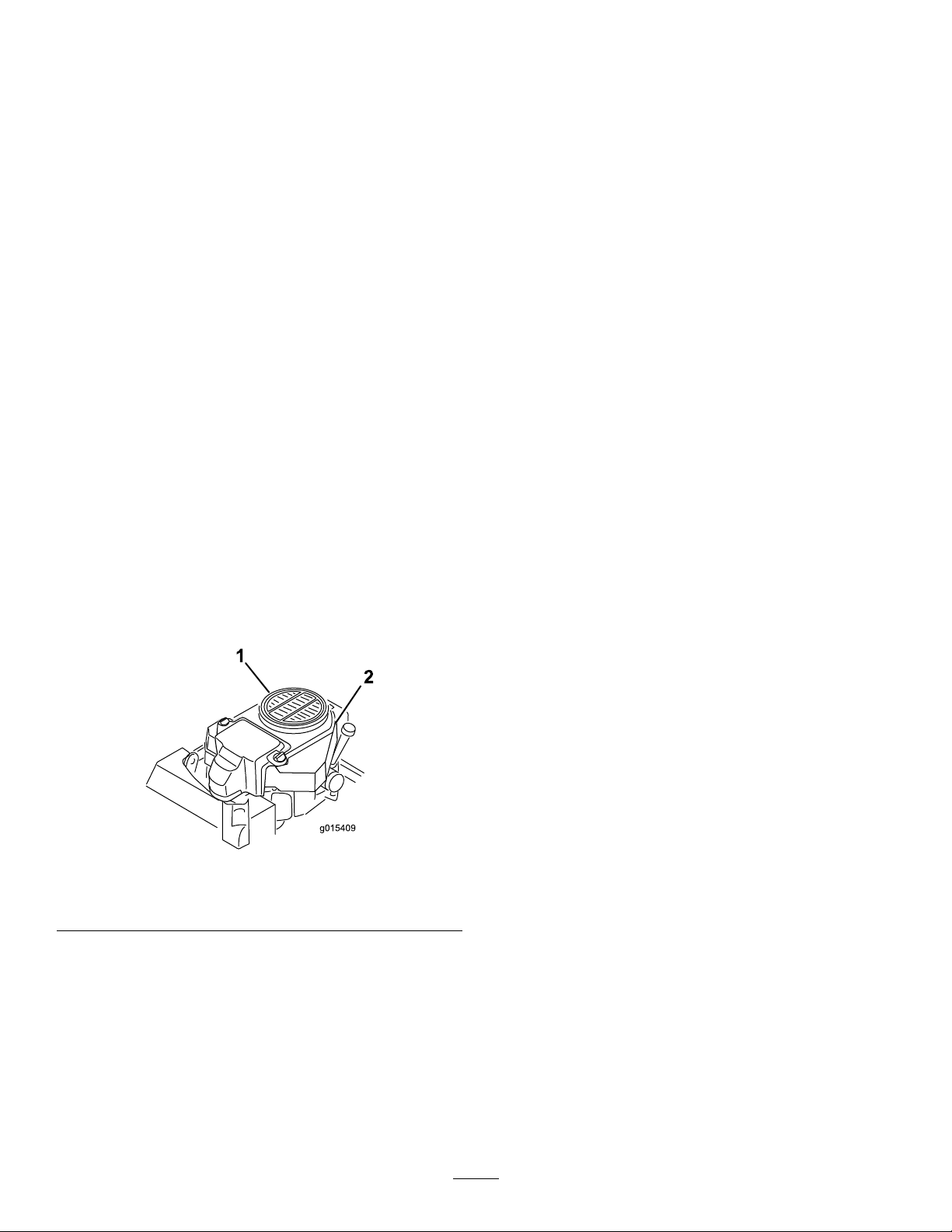
CoolingSystem
2
g015409
1
Maintenance
BrakeMaintenance
ServicingtheBrake
CleaningtheAir-IntakeScreen
ServiceInterval:Beforeeachuseordaily
Beforeeachuse,removeanybuildupofgrass,dirt,or
otherdebrisfromthecylinderandcylinderheadcooling
ns,airintakescreenontheywheelend,andthe
carburetor-governorleversandlinkage.Thiswillhelpensure
adequatecoolingandcorrectenginespeed,andwillreduce
thepossibilityofoverheatingormechanicaldamagetothe
engine.
CleaningtheCoolingSystem
ServiceInterval:Every100hours—Checkandcleanthe
enginecoolingnsandshrouds.
1.DisengagethePTOandsettheparkingbrake.
2.Stoptheengine,removethekey,andwaitforallmoving
partstostopbeforeleavingtheoperatingposition.
3.Removetheair-intakescreenandfanhousing(Figure
62).
4.Cleanthedebrisandgrassfromtheengineparts.
5.Installtheair-intakescreen,therecoilstarter,andthe
fanhousing(Figure62).
Beforeeachuse,checkthebrakesonalevelsurfaceandslope.
Alwayssettheparkingbrakewhenyoustopthemachineor
leaveitunattended.
Important:Iftheparkingbrakedoesnotholdsecurely,
anadjustmentisrequired.
CheckingtheParkingBrake
ServiceInterval:Beforeeachuseordaily
1.Parkthemachineonalevelsurface,disengagethePTO.
2.Stoptheengine,removethekey,andwaitforallmoving
partstostopbeforeleavingtheoperatingposition.
3.Releasethebrake.
Note:Thebrakebarsshouldliftoffthetiresandthe
handlevershouldtravelforwardtotheendoftheslot
inthecontrolpanel.
Note:Adjustthebrakeifneeded.
4.Engagethebrakeleveruntilthebrakebarsrstcontact
thetire(Figure63).
5.Measurethegapfromthefrontofthehandleverto
theendoftheslotinthecontrolpanelwhenthebrake
barcontactsthetire(Figure63).
1.Guardandengine
air-intakescreen
Note:Thismeasurementneedstobe19mm(3/4
inch).
Note:Adjustthebrakeifneeded.
Figure62
2.Fanhousing
45
Page 46
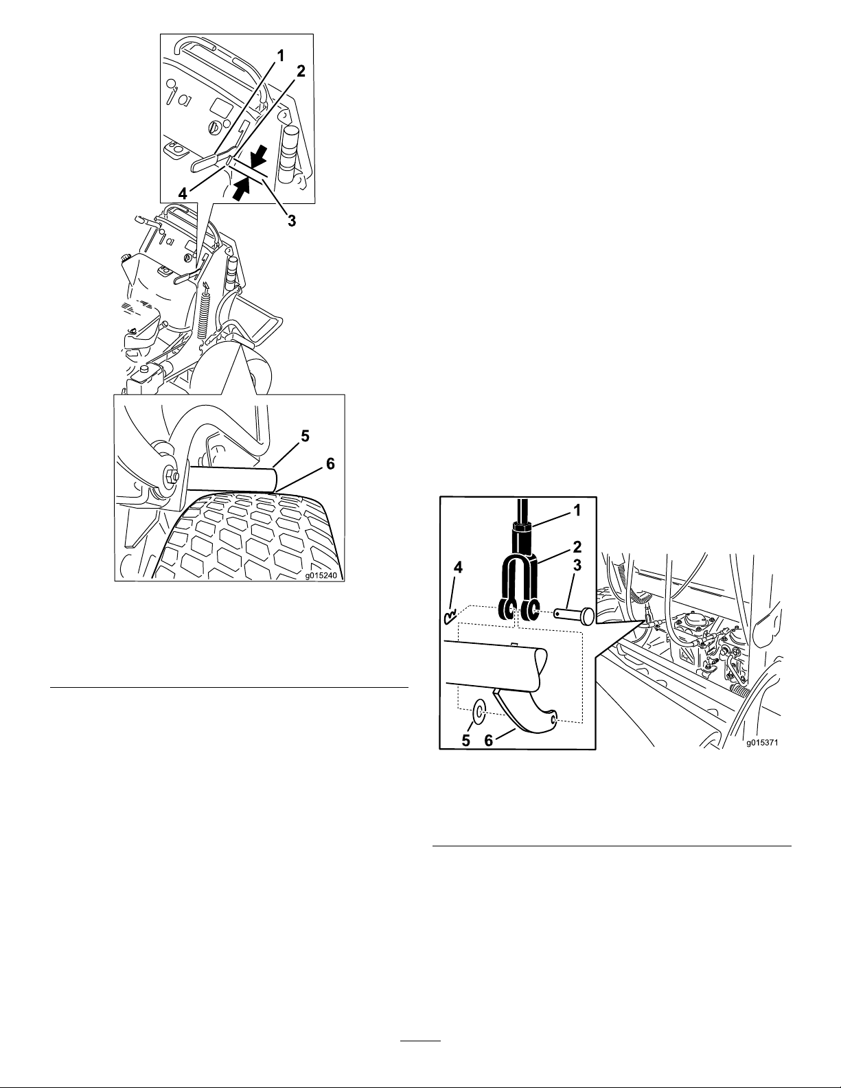
1
2
3
4
5
6
g015240
AdjustingtheBrakes
g015371
1
2
3
4
5 6
Iftheparkingbrakedoesnotholdsecurely ,anadjustment
isrequired.
1.Checkthebrakebeforeyouadjustit;refertoChecking
theParkingBrake(page45).
2.Parkthemachineonalevelsurface,disengagethe
PTO,andsettheparkingbrake.
3.Stoptheengine,removethekey,andwaitforallmoving
partstostopbeforeleavingtheoperatingposition.
4.Releasetheparkingbrake.
5.Toadjustthebrake,removethehairpincotterand
clevispinfromthelowerbrakeleverandyoke(Figure
64).
6.Loosenthejamnut(Figure64).
7.Rotatetheyoke(Figure64).
Note:Totightenthebrake,rotatetheyokeup.
Note:Toloosenthebrake,rotatetheyokedown.
8.Securetheyoketothelowerbrakeleverwiththe
hairpincotterpinandclevispin(Figure64).
9.Tightenthejamnut(Figure64).
10.Checkthebrakeoperationagain;refertoCheckingthe
ParkingBrake(page45).
Figure63
1.Handlever
2.Frontofhandlever
3.19mm(3/4inch)gap
4.Frontofslot
5.Brakebar
6.Brakebarjusttouching
thetire
Figure64
1.Jamnut4.Hairpincotterpin
2.Yoke5.Flatwasher
3.Clevispin
6.Lowerbrakelever
11.Afterthebrakeisadjusted,checktheleverswitch
(Figure65).
12.Checkthegapbetweenthebrakeleverandthefaceof
theswitchasshowninFigure65.
Note:Thegapneedstobewithin3mm(1/8inch)
withthebrakeengaged.
13.Ifneeded,loosenthescrewsholdingtheswitchand
adjusttheswitch.
46
Page 47
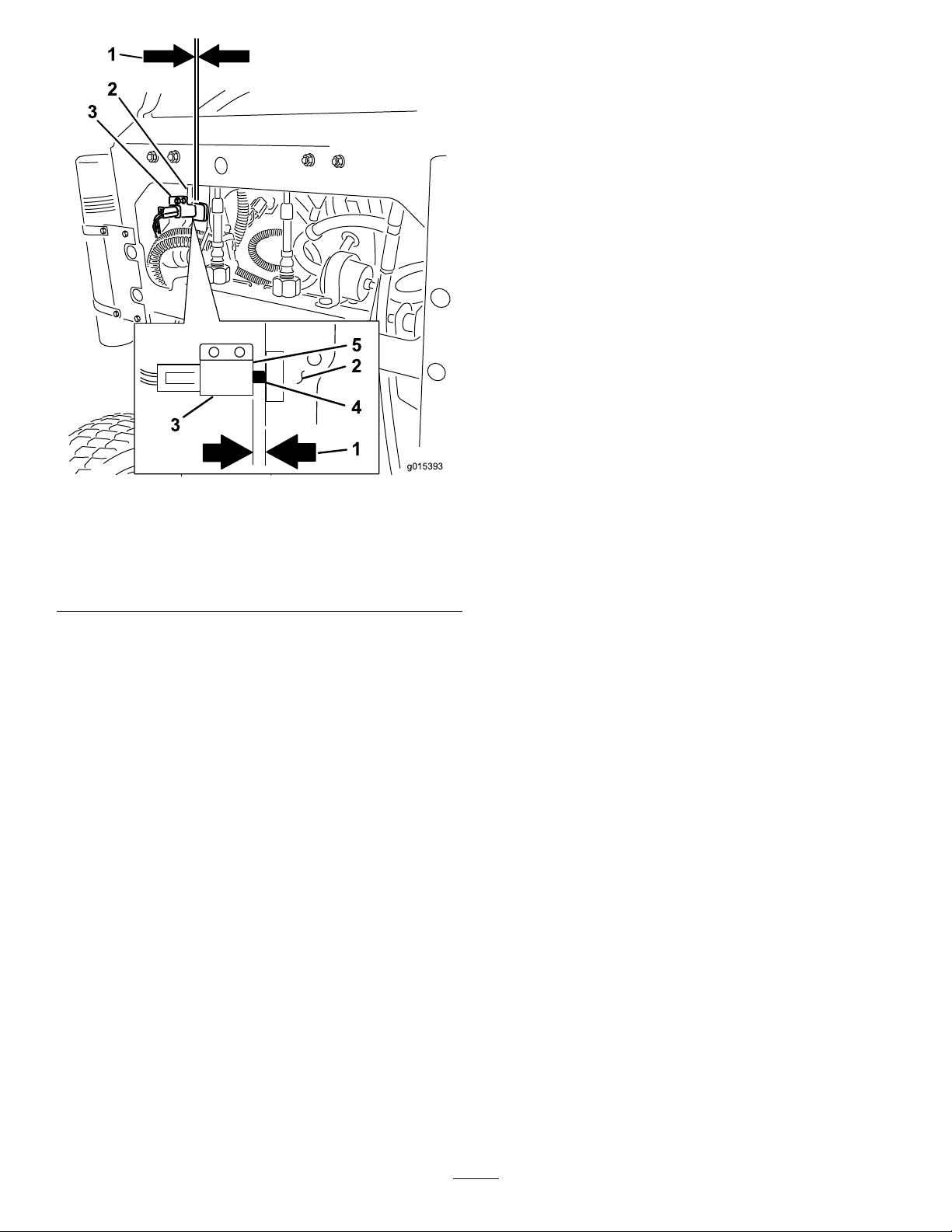
g015393
1
2
3
3
5
2
4
1
Figure65
BeltMaintenance
ReplacingtheMower-Deck Belt
ServiceInterval:Every100hours—Checkthemower-deck
belt.
Squeakingwhenthebeltisrotating,thebladeisslippingwhen
cuttinggrass,frayedbeltedges,burnmarks,andcracksare
signsofaworndeckbelt.
Replacethedeckbeltifanyoftheseconditionsareevident.
1.DisengagethePTOandsettheparkingbrake.
2.Stoptheengine,removethekey,andwaitforallmoving
partstostopbeforeleavingtheoperatingposition.
3.Unlatchandremovethebeltcovers.
4.Loosenthefrontidlerpulleybylooseningthenut
(Figure66andFigure67).
5.Removethewornmowerbelt(Figure66andFigure
67).
1.3mm(1/8inch)gap
neededbetweenthe
switchandthebrakelever
2.Brakelever
3.Switch
4.Switchbutton
5.Faceoftheswitch
6.Installthenewmowerbeltaroundthedeckpulleysand
clutchpulley(Figure66andFigure67).
7.Usingaratchetintheidlerarm,tightentheidlerpulley
untilthespringisstretched16.5cm(6.5inches)from
hooktohook(Figure66andFigure67).
8.Tightenthefrontidlerpulleybytighteningthenut
(Figure66andFigure67).
9.Installthebeltcoversontothecuttingunitandsecure
thelatches.
47
Page 48
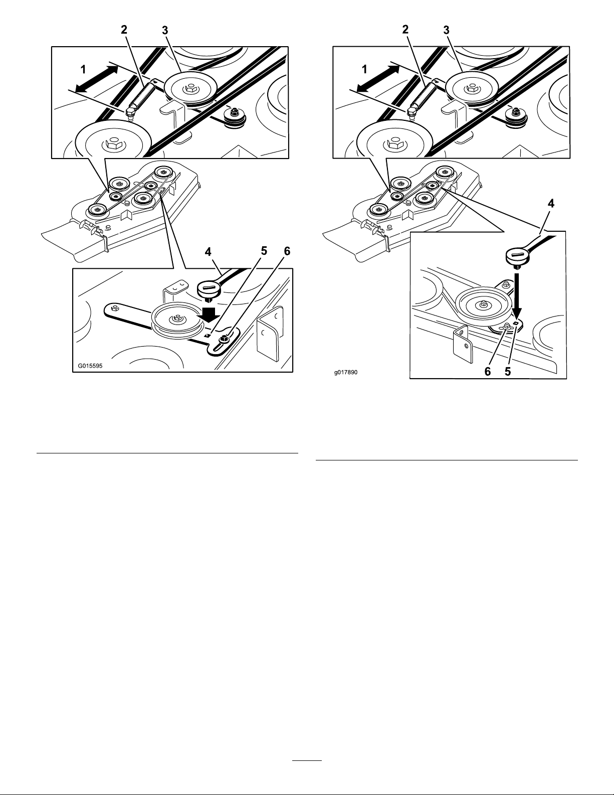
G015595
Figure66
6 5
g017890
1.16.5cm(6.5inches)from
hooktohook
2.Spring5.Squareholeforratchet
3.Spring-loadedidler
4.Ratchet
6.Nut
Figure67
1.16.5cm(6.5inches)from
hooktohook
2.Spring5.Squareholeforratchet
3.Spring-loadedidler
4.Ratchet
6.Nut
ReplacingthePump-DriveBelt
ServiceInterval:Every100hours—Checkthepump-drive
belt.
1.DisengagethePTOandsettheparkingbrake.
2.Stoptheengine,removethekey,andwaitforallmoving
partstostopbeforeleavingtheoperatingposition.
3.Removethemower-deckbelt.
4.Tiltthemachine;refertoRaisingtheMowerforAccess
(page30).
5.Removetheshoulderbolt,thenut,andthewasher
fromtheenginedeckandconnectedspring(Figure68).
48
Page 49
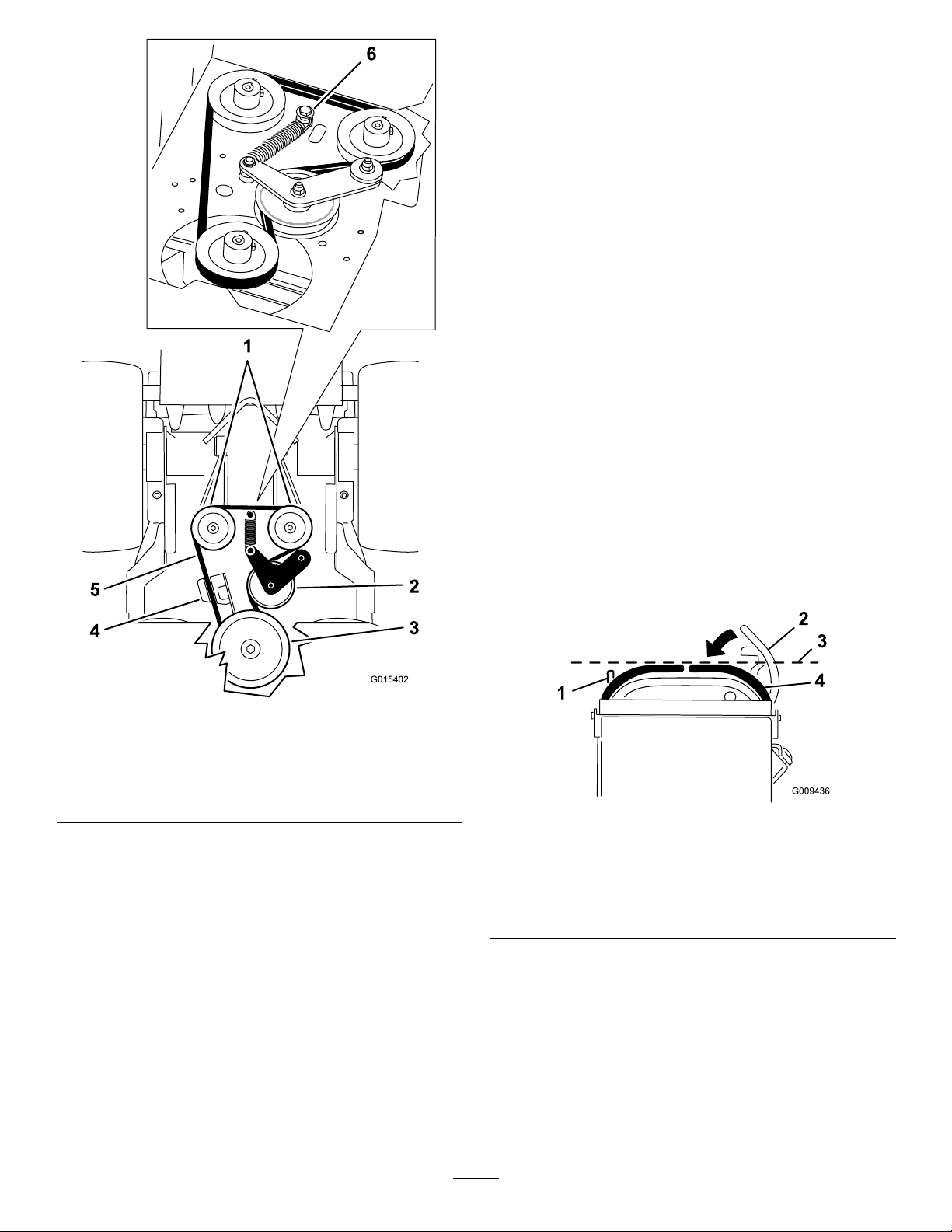
G015402
1
2
3
5
4
6
ControlsSystem
Maintenance
Adjustingthe Motion-Control-Handle Positions
AdjustingtheRightSideMotion-Control
Lever
Ifthemotion-controlleversdonotalignhorizontally ,adjust
therightsidemotion-controllever.
Note:Adjustthehorizontalalignmentbeforethefrontto
backalignment.
1.DisengagethePTO,movetherightsidemotion-control
levertotheneutralposition,andsettheparkingbrake.
2.Stoptheengine,removethekey,andwaitforallmoving
partstostopbeforeleavingtheoperatingposition.
3.Pushtherightmotion-controlleverdownoutofthe
neutral-lockedposition(Figure69).
Figure68
1.Hydraulicpumps
2.Idlerpulley5.Pump-drivebelt
3.Clutchpulley6.Shoulderbolt,nut,and
6.Removethepump-drivebelt(Figure68).
7.Installthenewbeltaroundtheclutchandthe2pump
pulleys.
8.Installthespringontotheshoulderboltandwasher,
andconnectittotheenginedeckwiththenut(Figure
68).
9.Lowerthemachinetotheoperatingposition.
10.Installthemower-deckbelt.
4.Clutchretainer
washer
4.Checkiftherightmotion-controlleveraligns
horizontallywiththeleftmotion-controllever(Figure
69).
Figure69
1.Leftmotion-controllever3.Checkthehorizontal
2.Rightmotion-controllever
intheneutral-locked
position
5.Toadjusttherightmotion-controlleverhorizontally ,
thecamneedstobeadjusted.
6.Releasethecushionfromtherearofthemachine.
7.Loosenthenutholdingthecam(Figure70).
alignmenthere
4.Rightmotion-controllever
49
Page 50
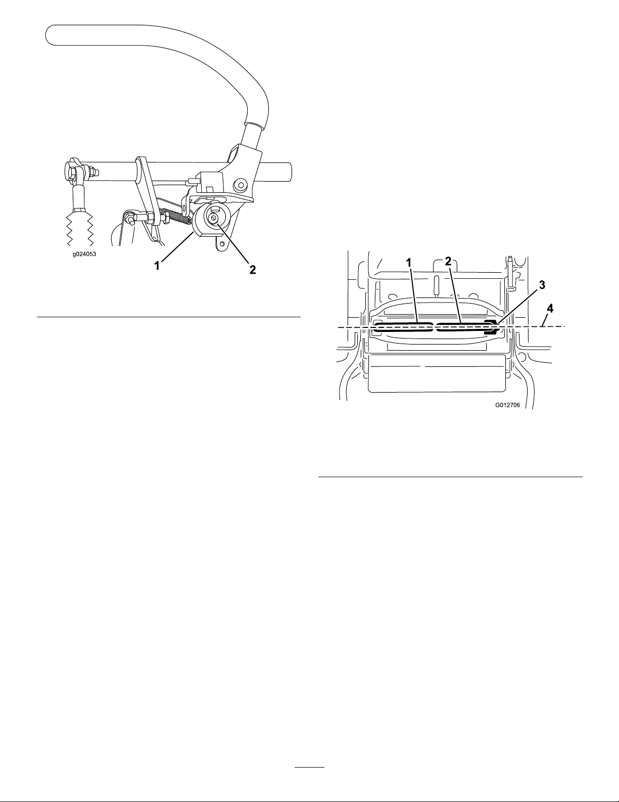
Figure70
G012706
1
2
3
4
AdjustingtheNeutralPositionforthe
Motion-ControlLevers
Important:Ensurethetrackingofthemoweriscorrect
afteradjustingthemotion-controllevers.Adjustingthe
trackingandaligningthemotion-controlleversfrontto
backisthesameprocedure(Figure71).
Note:Adjustthehorizontalalignmentbeforethefrontto
backalignment.
Ifthemotion-controlleversdonotalignfronttoback,or
therightsidecontrolleverdoesnotmoveeasilyintothe
neutral-lockposition,adjustmentisrequired.
1.Afterthehorizontalalignmentisnished,checkthe
fronttobackalignmentbyslightlypushingthecontrol
leversforwardtotakeupanyslackinthelinkagefor
thecontrollevers(Figure71).
1.Cam
2.Nut
8.Adjustthecamuntilitalignswiththeleft
motion-controlleverandtightenthenutforthecam.
Note:Movingthecamclockwise(inthevertical
position)lowersthehandle,whilemovingit
counterclockwise(intheverticalposition)raisesthe
handle.
Important:Ensurethattheatportionofthe
camdoesnotgoaboveaverticalposition(rightor
left),oryoumaycausedamagetotheswitch.
Figure71
1.Leftmotion-controllever
2.Rightmotion-controllever4.Alignthecontrollevers
3.Neutral-lockedposition
fronttoback
2.Ensuretherightmotion-controllevermoveseasilyinto
theneutral-lockposition.
Note:Turnthecableadjustmentclockwiseto
movethemotion-controlhandleforward.Turn
thecableadjustmentcounterclockwisetomovethe
motion-controlhandlerearward.
3.Rotatethecableadjustmentonrightsidewhen
adjustmentisneeded.
Note:Adjustthecableadjustmentinquarter-turn
increments.
4.Aftertherightmotion-controllevermoveseasilyinto
theneutral-lockposition,adjusttheleftmotion-control
levertoalignwiththerightmotion-controllever.
5.Checkforpropertracking;refertoAdjustingthe
Tracking(page41).
6.Installthecablelockontothecable-adjustingnutsto
securetheadjustment(Figure72).
50
Page 51
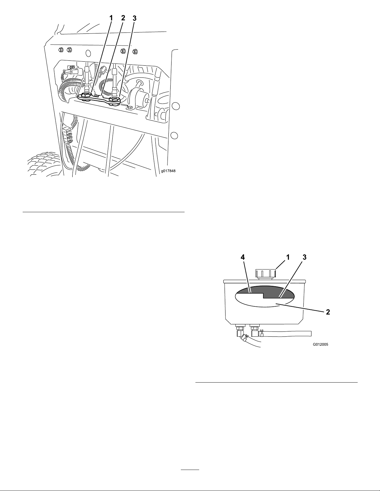
3
g017848
1.Leftcableadjustment
G012005
4 1 3
2
2.Cablelock
Figure72
3.Rightcableadjustment
HydraulicSystem
Maintenance
ServicingtheHydraulic System
HydraulicOilType:T oro
orMobil
HydraulicSystemOilCapacity:2.0L(67oz)
Important:Useoilspecied.Otheruidscouldcause
systemdamage.
®
115W -50syntheticmotoroil.
®
HYPR-OIL
CheckingtheHydraulicFluid
ServiceInterval:Aftertherst8hours
Every50hours
Note:Thereare2waystocheckthehydraulicoil;whenthe
oiliswarm,orwhentheoiliscold.Thebafeinsidethetank
has2levelsdependingiftheoiliswarmorcold.
1.Positionthemachineonalevelsurface.
2.Disengagethepowertakeoff(PTO)andshutoffthe
engine.
3.Waitforallmovingpartstostopbeforeleavingthe
operatingpositionandthensettheparkingbrake.
4.Cleantheareaaroundthecapandthellerneckofthe
hydraulictank(Figure73).
™
500hydraulicoil
Figure73
1.Cap3.Colduidlevel—full
2.Bafe4.Hotuidlevel—full
5.Removethecapfromthellerneck(Figure73).
Note:Lookinsidetochecktheuidlevelinthe
reservoir.
6.Adduidtothereservoiruntilitreachesthecoldlevel
ofthebafe.
7.Runthemachineatlowidlefor15minutestoallow
anyairtopurgeoutofthesystemandwarmtheuid;
51
refertoStartingandStoppingtheEngine(page20).
Page 52
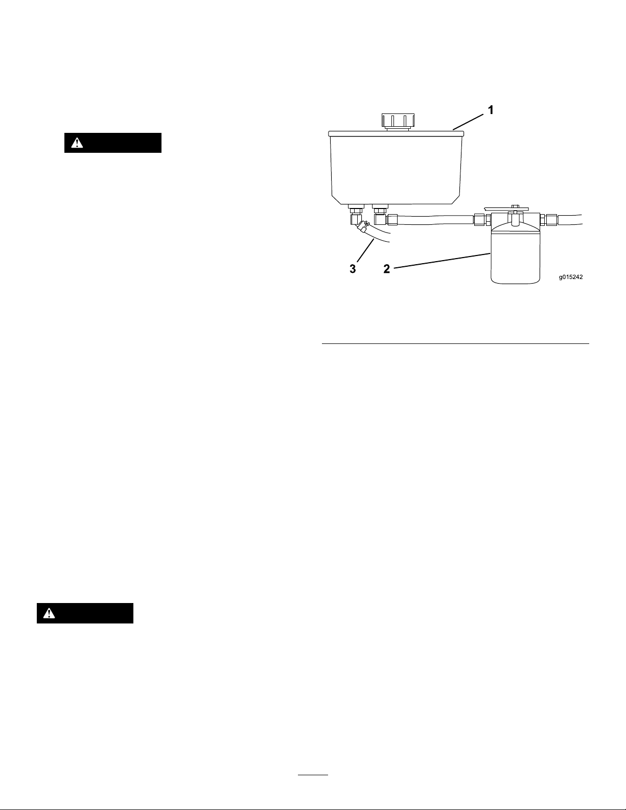
8.Checktheuidlevelwhiletheuidiswarm.
g015242
1
3 2
Note:Ifrequired,adduidtothereservoiruntilitis
betweenthehotlevelandthecoldlevel.
Note:Theuidlevelshouldbebelowthehotlevelof
thebafewhentheuidiswarm(Figure73).
9.Installthecaponthellerneck.
WARNING
Hydraulicuidescapingunderpressurecan
penetrateskinandcauseinjury.
•Ifhydraulicuidisinjectedintotheskin,
itmustbesurgicallyremovedwithinafew
hoursbyadoctorfamiliarwiththistype
ofinjury.Gangrenemayresultifthisis
notdone.
•Keepyourbodyandhandsawayfrom
pinholeleaksornozzlesthateject
high-pressurehydraulicuid.
•Usecardboardorpapertondhydraulic
leaks.
4.Locatethefronthydraulichoseunderthehydraulic
tank,andplaceadrainpanunderthetank(Figure74).
5.Loosenthehoseclampandmoveitdownthehose.
6.Removethefronthydraulichose,andallowtheuidto
runoutofthetank.
Figure74
1.Hydraulictank3.Fronthydraulichose
2.Hydrauliclter
•Safelyrelieveallpressureinthehydraulic
systembeforeperforminganyworkonthe
hydraulicsystem.
•Makesureallhydraulic-uidhosesarein
goodcondition,andallthatthehydraulic
connectionsandttingsaretightbefore
applyingpressuretohydraulicsystem.
ReplacingtheHydraulicFluid
ServiceInterval:Every250hours—Changethehydraulic
lterandhydraulicoilwhenusingMobil
1oil.
Every500hours/Y early(whichevercomes
rst)—Changethehydrauliclterandhydraulicoil
whenusingToro
Note:Changethehydraulicuidmorefrequentlyinsevere
conditionsorinahotoperatingclimate.
®
HYPR-OIL
™
500hydraulicoil.
WARNING
Hothydraulicuidcancausesevereburns.
7.Changethehydrauliclter;refertoReplacingthe
HydraulicFilter(page53).
8.Connectthehydraulichoseunderthetank.
9.Adduidtothetankuntilitreachesthecoldbafe
ofthetank.
Important:Useoilspeciedorequivalent.Other
uidscouldcausesystemdamage.
10.Installthehydraulic-tankcap.
11.Starttheengineandletitrunforabout2minutesto
®
purgeairfromthesystem.
12.Stoptheengineandcheckforleaks.
Note:Ifoneorbothwheelswillnotdrive,referto
BleedingtheHydraulicSystem(page53).
13.Checktheleveloftheuidandadduid,ifrequired.
Note:Donotoverll.
Allowthehydraulicuidtocoolbeforeperforming
anymaintenancetothehydraulicsystem.
1.DisengagethePTOandsettheparkingbrake.
2.Stoptheengineandwaitforallmovingpartstostop
beforeleavingtheoperatingposition.
3.Removehydraulic-reservoircap.
52
Page 53
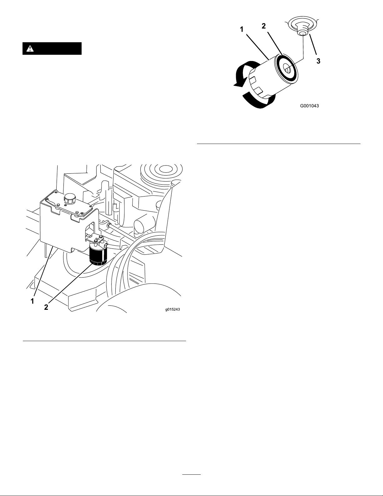
ReplacingtheHydraulicFilter
g015243
1
2
ServiceInterval:Aftertherst8hours
WARNING
Hothydraulicuidcancausesevereburns.
Allowthehydraulicuidtocoolbeforeperforming
anymaintenancetothehydraulicsystem.
Important:Donotsubstitutewithanautomotiveoil
lter,orseverehydraulicsystemdamagemayresult.
1.DisengagethePTOandsettheparkingbrake.
2.Stoptheengineandwaitforallmovingpartstostop
beforeleavingtheoperatingposition.
1.Hydrauliclter
2.Gasket
Figure76
3.Adapter
3.Locatethelterandplaceadrainpanunderlter
(Figure75).
Figure75
1.Hydraulictank
2.Hydrauliclter
4.Removetheoldlterandwipethelter-adaptergasket
surfaceclean(Figure76).
5.Applyathincoatofhydraulicuidtotherubbergasket
onthereplacementlter.
6.Installthereplacementhydrauliclterontothelter
adapter.
7.Turntheoillterclockwiseuntiltherubbergasket
contactsthelteradapter,thentightenthelteran
additional1/2turn(Figure76).
8.Cleanupanyspilleduid.
9.Checktheuidinthereservoir,andadduidtothe
tankuntilitreachesthecoldbafeofthetank.
Important:Usetheoilspeciedorequivalent.
Otheruidscouldcausesystemdamage.
10.Starttheengineandletitrunforabout2minutesto
purgeairfromthesystem.
11.Stoptheengineandcheckforleaks.
Note:Ifoneorbothwheelswillnotdrive,referto
BleedingtheHydraulicSystem(page53).
12.Checktheleveloftheuidandadduid,ifrequired.
Note:Donotoverll.
BleedingtheHydraulicSystem
Thetractionsystemisself-bleeding,however,itmaybe
necessarytobleedthesystemifuidischangedorafterwork
isperformedonthesystem.
1.DisengagethePTOandsettheparkingbrake.
2.Stoptheengineandwaitforallmovingpartstostop
beforeleavingtheoperatingposition.
3.Raisetherearofthemachineontojackstandshigh
enoughtoraisethedrivewheelsofftheground.
4.Starttheengineandmovethethrottlecontroltothe
idleposition.
Note:Ifthedrivewheeldoesnotrotate,itispossible
toassistthepurgingofthesystembycarefullyrotating
thetireintheforwarddirection.
5.Checkthehydraulicuidlevelasitdrops,andadduid
asrequiredtomaintaintheproperlevel.
6.Repeatthisprocedurefortheoppositewheel.
7.Thoroughlycleantheareaaroundeachofthecharge
pumphousings.
53
Page 54
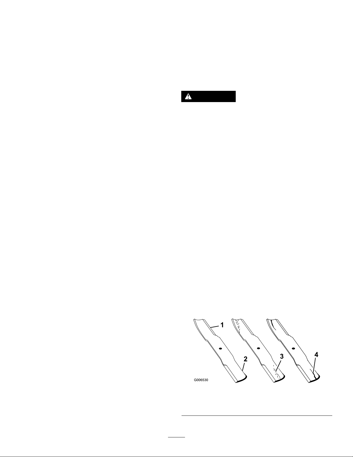
CheckingtheHydraulicLines
ServiceInterval:Every100hours
Checkhydraulichosesandhosesforleaks,loosettings,
kinkedhoses,loosemountingsupports,wear,general
weathering,andchemicaldeterioration.Makeanynecessary
repairsbeforeoperating.
Note:Keepareasaroundthehydraulicsystemcleanfrom
grassanddebrisbuildup.
Note:Extendedoperatingtimeathightemperaturesinahot
climatemayleadtodeteriorationofhosesandseals.Inspect
morefrequentlyinahotclimate,andchangethehydraulic
oilandltermorefrequently.
MowerDeck Maintenance
ServicingtheCuttingBlades
Toensureasuperiorqualityofcut,keepthebladessharp.
Forconvenientsharpeningandreplacement,youmaywant
tokeepextrabladesonhand.
WARNING
Awornordamagedbladecanbreak,andapiece
ofthebladecouldbethrownintotheoperator's
orbystanders’area,resultinginseriouspersonal
injuryordeath.
•Inspectthebladesperiodicallyforwearor
damage.
•Replaceawornordamagedblade.
BeforeInspectingorServicingthe
Blades
Parkthemachineonalevelsurface,disengagethebladesand
settheparkingbrake.Turntheignitionkeytooff.Remove
thekey,anddisconnectthesparkplugwiresfromthespark
plugs.
InspectingtheBlades
ServiceInterval:Beforeeachuseordaily
1.Inspectthecuttingedges(Figure77).
2.Iftheedgesarenotsharporhavenicks,removeand
sharpentheblade;refertoSharpeningtheBlades(page
55).
3.Inspecttheblades,especiallyinthecurvedarea.
4.Ifyounoticeanycracks,wear,oraslotforminginthis
area,immediatelyinstallanewblade(Figure77).
Figure77
1.Cuttingedge3.Wear/slotforming
2.Curvedarea4.Crack
54
Page 55
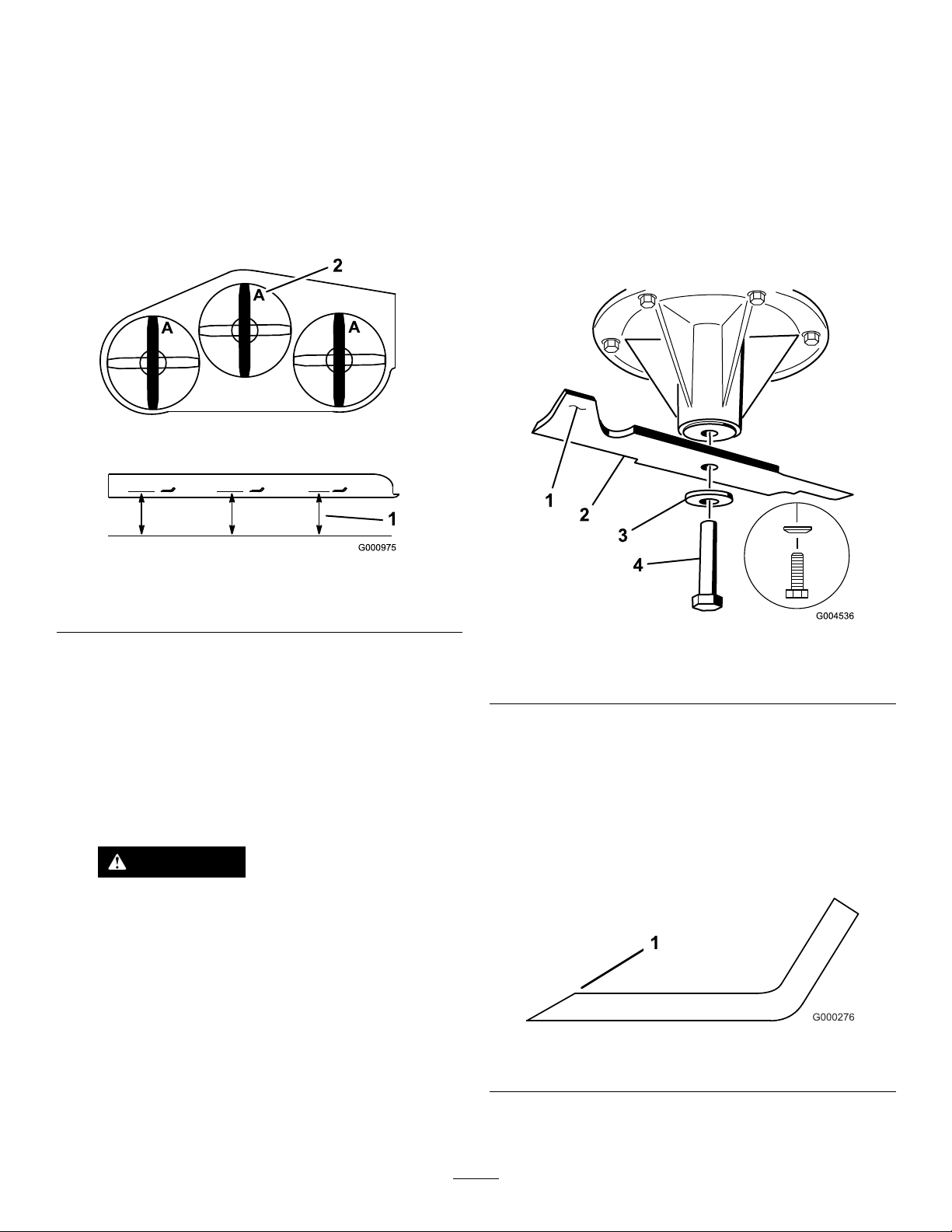
CheckingforBentBlades
RemovingtheBlades
1.DisengagethePTO,movethemotion-controlleversto
theneutral-lockedposition,andsettheparkingbrake.
2.Stoptheengine,removethekey,andwaitforallmoving
partstostopbeforeleavingtheoperatingposition.
3.Rotatethebladesuntiltheendsfaceforwardand
backward.
4.Measurefromalevelsurfacetothecuttingedge,
positionA,oftheblades(Figure78).
Bladesmustbereplacedifasolidobjectishit,ifthe
bladeisoutofbalance,orifthebladeisbent.Toensure
optimumperformanceandcontinuedsafetyconformance
ofthemachine,usegenuineTororeplacementblades.
Replacementbladesmadebyothermanufacturersmayresult
innonconformancewithsafetystandards.
1.Holdthebladeendusingaragorathickly-padded
glove.
2.Removethebladebolt,thecurvedwasher,andthe
bladefromthespindleshaft(Figure79).
Figure78
1.Measureherefromblade
tohardsurface
5.Rotatetheoppositeendsofthebladesforward.
6.Measurefromalevelsurfacetothecuttingedgeofthe
bladesatthesamepositionasinstep4above.
Note:Thedifferencebetweenthedimensions
obtainedinsteps4and5mustnotexceed3mm
(1/8inch).
Note:Ifthisdimensionexceeds3mm(1/8inch),the
bladeisbentandmustbereplaced.
2.PositionA
WARNING
Abladethatisbentordamagedcouldbreak
apartandcouldseriouslyinjureorkillyouor
bystanders.
•Alwaysreplacebentordamagedblade
withanewblade.
•Donotleorcreatesharpnotchesinthe
edgesorsurfacesoftheblade.
Figure79
1.Sailareaoftheblade3.Curvedwasher
2.Blade4.Bladebolt
SharpeningtheBlades
1.Usealetosharpenthecuttingedgeatbothendsof
theblade(Figure80).
Note:Maintaintheoriginalangle.
Note:Thebladeretainsbalanceifthesameamount
ofmaterialisremovedfrombothcuttingedges.
Figure80
1.Sharpenattheoriginalangle
2.Checkthebalanceofthebladebyputtingitonablade
balancer(Figure81).
55
Page 56
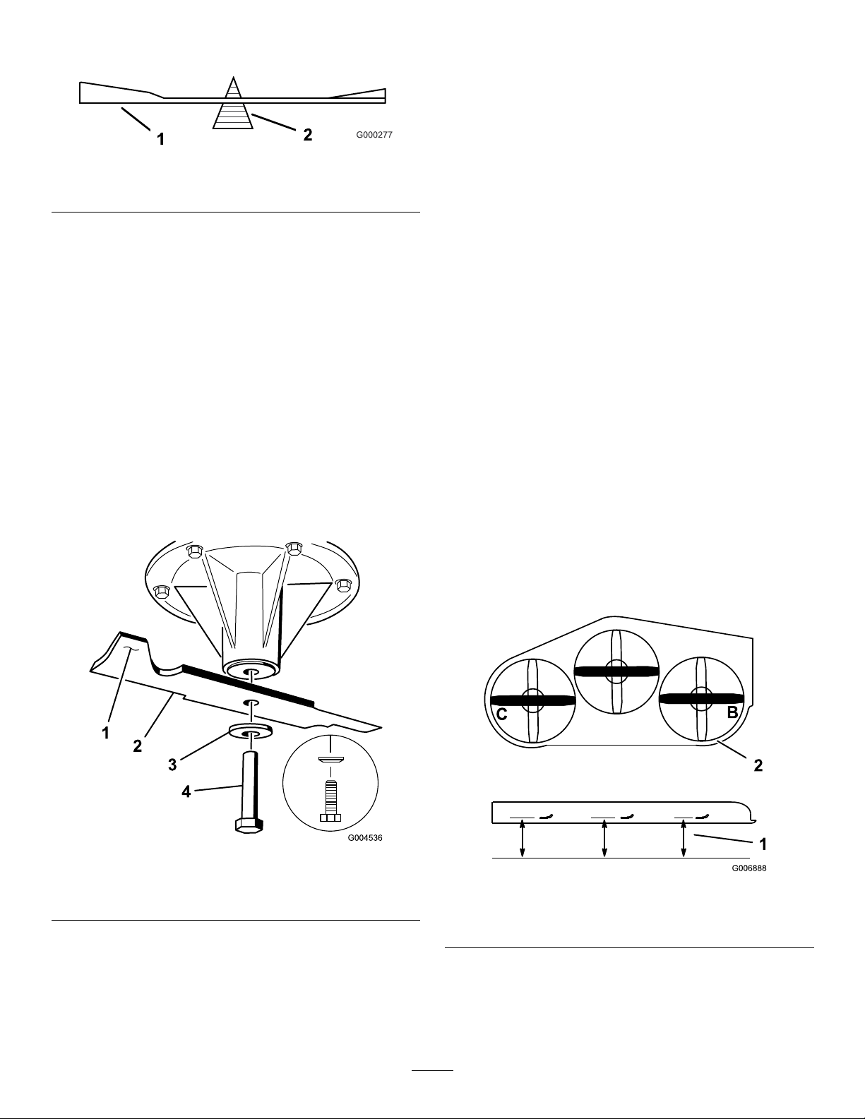
Note:Ifthebladestaysinahorizontalposition,the
bladeisbalancedandcanbeused.
Figure81
CorrectingtheMower Quality-of-Cut
Ifonedeckbladecutslowerthantheother,correctitas
follows:
Note:Tireairpressureiscriticalintheseprocedures;make
surethereartireshavethecorrectpressure.
1.Blade2.Balancer
3.Ifthebladeisnotbalanced,lesomemetalofftheend
ofthesailareaonly(Figure79).
4.Repeatthisprocedureuntilthebladeisbalanced.
InstallingtheBlades
1.Installthebladeontothespindleshaft(Figure82).
Important:Thecurvedpartoftheblademustbe
pointingupwardtowardtheinsideofthemowerto
ensurepropercutting .
2.Installthespringdiskandbladebolt(Figure82).
Note:Thespring-diskconemustbeinstalledtoward
thebolthead(Figure82).
3.Torquethebladeboltto115to150N-m(85to
110ft-lb).
1.DisengagethePTOandsettheparkingbrake.
2.Stoptheengine,removethekey,andwaitforallmoving
partstostopbeforeleavingtheoperatingposition.
3.Disconnectthesparkplugwire(s)fromthespark
plug(s).
4.Adjustthetirepressureinthereartiresto83to97kPa
(12to14psi).
5.Checkthatthebladesandspindleshaftsarenotbent;
refertoCheckingforBentBlades(page55).
6.Settheheight-of-cuttothe7.6cm(3inches)position;
refertoAdjustingtheHeight-of-Cut(page26).
CheckingtheMowerDeckSide-to-Side
Height
1.Adjusttherear-tirepressure.
2.Ensurethatthebladesarenotbent;refertoChecking
forBentBlades(page55).
3.Positionthebladesside-to-side.
4.MeasureattheBandClocationsfromalevelsurface
tothecuttingedgeofbladetips(Figure83).
Figure82
1.Sailareaoftheblade3.Springdisk
2.Blade4.Bladebolt
Figure83
1.Measurefromalevel
surface
5.ThedifferencebetweenmeasurementsBandCshould
benomorethan6mm(1/4inch).
Note:Ifitisnotcorrect,refertoChangingtheMower
DeckSide-to-SideHeight(page57).
56
2.Measurethebladeat
pointsBandC
Page 57
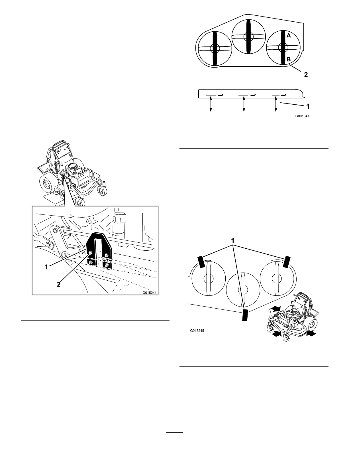
ChangingtheMowerDeckSide-to-Side
G015244
G015245
Height
Changingtheside-to-sideheightisdonebyadjustingthe
rear-tirepressureandU-platesonthesideoftheenginedeck.
1.Changetherear-tirepressure.
Note:Dothistothecorrespondingsidethatneeds
adjustment.
2.LocatetheU-platesonthesideoftheenginedeck
(Figure84).
3.LoosentheU-plateon1side,andadjustitupordown
tomakethedifferencebetweenmeasurementsBandC
nomorethana6mm(1/4inch)asshowninFigure84.
4.ProceedtoCheckingtheMowerDeckFront-to-Rear
Pitch(page57).
Figure85
1.Measurethebladeat
pointsAandB
2.Measurefromalevel
surface
4.Ifitisnotcorrect,refertoChangingtheMowerDeck
Front-to-RearPitch(page57).
ChangingtheMowerDeck
Front-to-RearPitch
Figure84
1.U-plate2.Nutsandbolts
CheckingtheMowerDeckFront-to-Rear
Pitch
1.Adjustthetirepressureinthereartirestothecorrect
specications.
Changingthefront-to-rearpitchisdonebyadjustingthe
frontheight-of-cutposts.
1.Place3piecesof2x4woodunderthemowerdeckas
showninFigure86.
2.Standthe2x4piecesonthe4-inchpart.
Figure86
1.2x4pieceofwoodunderthemowerdeck
2.Position1bladefront-to-rear.MeasureatAandB
locationsfromalevelsurfacetothecuttingedgeof
thebladetips(Figure85).
Note:Themowerbladeshouldbe6mm(1/4inch)
lowerinfrontatAthanintherearatB.
3.Rotatethebladesandrepeatforotherblades.
3.Loosenboththefrontandrearnutsontheadjustment
rods(Figure87).
Note:Theweightofthemowerdeckmustberesting
onall3ofthe2x4pieces(Figure87).
Note:Thebacklipofthemowerdeckisbuilt6mm
(1/4inch)lowerthanthefrontlipofthemowerdeck.
57
Page 58
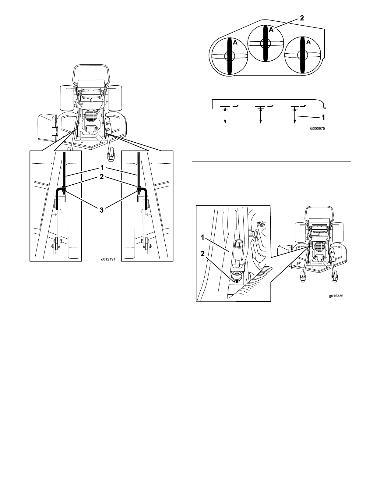
4.Tightenboththefrontandrearnuts.
g015336
1
2
5.Checkthefront-to-rearpitchofthecuttingunit.
6.Ifthedimensionsarenotcorrect,adjustthefrontand
rearnutsoneithersidetogetthecorrectfront-to-rear
pitch(Figure87).
Figure88
Figure87
1.Adjustmentrods3.Frontnuts
2.Rearnuts
MatchingtheHeight-of-Cut
1.Checkthereartirepressure.
1.Measurefromalevel
surface
2.Measurethebladeatpoint
A
5.Ifitdoesnotmeasurecorrectly,locatetheheight-of-cut
rodontherightsideofthemachine(Figure89).
6.Adjusttheadjustmentboltuntilthebladetipsmatch
7.6cm(3inches)asshowninFigure89.
Figure89
1.Height-of-cutrod
2.Adjustmentbolt
2.Settheheight-of-cuttothe7.6cm(3inches)position;
refertoAdjustingtheHeight-of-Cut(page26).
3.Withthemachineonlevelsurface,positiononeblade
front-to-rear.
4.MeasureatA,andfromalevelsurfacetothecutting
edgeofthebladetips(Figure88).
Note:Themeasurementshouldbe7.6cm(3inches).
58
Page 59
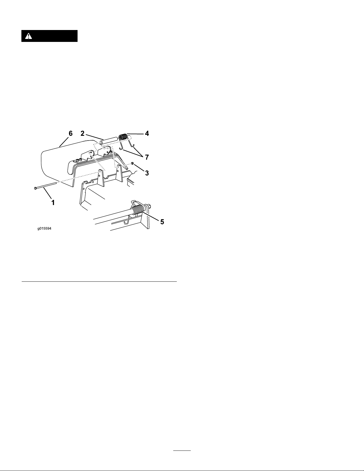
ReplacingtheGrassDeector
g015594
1
6 2
4
7
3
5
Cleaning
WARNING
Anuncovereddischargeopeningcouldallowthe
lawnmowertothrowobjectsintheoperator'sor
bystander'sdirectionandresultinseriousinjury.
Also,contactwiththebladecouldoccur.
Donotoperatethelawnmowerunlessyouinstall
acoverplate,amulchplate,grassdeector,or
bagger.
1.Removethelocknut,bolt,spring,andspacerholding
thedeectortothepivotbrackets(Figure90).
CleaningundertheMower
ServiceInterval:Beforeeachuseordaily
Removethegrassbuildupunderthemowerdaily.
1.DisengagethePTO ,movethemotioncontrolleversto
theneutrallockedpositionandsettheparkingbrake.
2.Stoptheengine,removethekey,andwaitforallmoving
partstostopbeforeleavingtheoperatingposition.
3.Raisethefrontofthemachineandusejackstandsto
supportthemower.
DisposingofWaste
Engineoil,batteries,hydraulicoil,andenginecoolantare
pollutantstotheenvironment.Disposeoftheseaccordingto
yourstateandlocalregulations.
Figure90
1.Bolt
2.Spacer6.Grassdeector
3.Locknut
4.Spring
2.Removethedamagedorworngrassdeector.
3.Placethespacerandthespringontothegrassdeector.
4.Place1J-endofthespringbehindthedeckedge.
Note:Makesure1J-endofspringisinstalledbehind
deckedgebeforeinstallingtheboltasshowninFigure
90.
5.Installtheboltandthenut.
6.Place1J-hookendofthespringaroundthegrass
deector(Figure90).
Important:Thegrassdeectormustbeable
torotate.Liftthedeectoruptothefullopen
position,andensurethatitrotatesintothefull
downposition.
5.Spring(installed)
7.J-hookendofthespring
59
Page 60

Storage
CleaningandStorage
1.Disengagethepowertakeoff(PTO),settheparking
brake,turntheignitionkeytooff,andremovethekey.
2.Removegrassclippings,dirt,andgrimefromthe
externalpartsoftheentiremachine,especiallythe
engine.
Important:Youcanwashthemachinewithamild
detergentandwater.Donotpressurewashthe
machine.Avoidexcessiveuseofwater,especially
nearthedrivesystemandengine.Pressure
washingcanforcedirtandwaterintocriticalparts,
suchasspindlebearingsandelectricalswitches.
3.Cleandirtandchafffromtheoutsideoftheengine
cylinderheadnsandblowerhousing.
4.Checkthebrake;refertoServicingtheBrake(page45).
5.Servicetheaircleaner;refertoServicingtheAir
Cleaner(page34).
6.Greasethemachine;refertoLubricatingtheMachine
(page32).
7.Changetheengineoil;refertoChangingtheEngine
Oil(page36).
8.Checkthetirepressure;refertoCheckingtheTire
Pressure(page43).
9.Forlong-termstorage:
A.Addstabilizer/conditioneradditivetofuelinthe
tank.
B.Runenginetodistributeconditionedfuelthrough
thefuelsystem(5minutes).
C.Stopengine,allowtocoolanddrainthefueltank;
refertoServicingtheFuelTankin,oroperate
engineuntilitstops.
D.Restartengineandrununtilitstops.Repeat,on
Chokeuntilenginewillnotrestart.
E.Disposeoffuelproperly.Recycleasperlocal
codes.
13.Storethemachineinaclean,drygarageorstoragearea.
Removethekeyfromtheignitionswitchandkeepit
inamemorableplace.Coverthemachinetoprotect
itandkeepitclean.
Note:Donotstorestabilizer/conditioned
gasolineover90days.
10.Removethesparkplug(s)andcheckitscondition;refer
toServicingtheSparkPlug(page37).Withthespark
plug(s)removedfromtheengine,pourtwotablespoons
ofengineoilintothesparkplughole.Nowusethe
startertocranktheengineanddistributetheoilinside
thecylinder.Installthesparkplug(s).Donotinstallthe
wireonthesparkplug(s).
11.Checkandtightenallbolts,nuts,andscrews.Repairor
replaceanypartthatisdamagedordefective.
12.Paintallscratchedorbaremetalsurfaces.Paintis
availablefromyourAuthorizedServiceDealer.
60
Page 61

Troubleshooting
Problem
Theenginewillnotstart,startshard,or
failstokeeprunning.
Theenginelosespower.
PossibleCauseCorrectiveAction
1.Fueltankisempty.
2.Chokeisnoton.
3.Sparkplugwireislooseor
disconnected.
4.Sparkplugispitted,fouled,orthegap
isincorrect.
5.Aircleanerisdirty.
6.Dirtinthefuellter.6.Replacethefuellter.
7.Dirt,water,orstalefuelisinthefuel
system.
8.Thegapbetweenthesafetyinterlock
switchesisnotcorrect.
1.Engineloadisexcessive.1.Reducethegroundspeed.
2.Aircleanerisdirty.
3.Oillevelinthecrankcaseislow.
4.Coolingnsandairpassagesunder
theengineblowerhousingareplugged.
5.Sparkplugispitted,fouled,orthegap
isincorrect.
6.Ventholeinthefuelcapisplugged.6.Cleanorreplacethefuelcap.
7.Dirtinthefuellter.7.Replacethefuellter.
8.Dirt,water,orstalefuelisinthefuel
system.
1.Fillthefueltankwithgasoline.
2.Movethechokelevertochokeposition.
3.Installwireonsparkplug.
4.Installanew,correctlygappedspark
plug.
5.Servicetheair-cleanerelement.
7.ContactanAuthorizedServiceDealer.
8.ContactanAuthorizedServiceDealer.
2.Servicetheaircleaner.
3.Addoiltothecrankcase.
4.Removetheobstructionfromthe
coolingnsandairpassages.
5.Installanew,correctlygappedspark
plug.
8.ContactanAuthorizedServiceDealer.
Theengineoverheats.
Themachinedoesnotdrive.
Thereisanabnormalvibration.
Thecuttingheightisuneven.
1.Engineloadisexcessive.1.Reducethegroundspeed.
2.Oillevelinthecrankcaseislow.
3.Coolingnsandairpassagesunder
theengineblowerhousingareplugged.
1.Hydraulicoilreservoirlow.1.Addhydraulicoiltothereservoir.
2.Airinthehydraulicsystem.2.Bleedtheairoutthehydraulicsystem.
3.Pump-drivebeltslipping.3.Replacethepump-drivebelt.
4.Pump-drivebeltidlerspringmissing.4.Replacethepump-drive-beltidler
5.Pumpbypassvalvesareopen.5.Tightentheby-passvalves.Torqueto
1.Cuttingblade(s)is/arebentor
unbalanced.
2.Blade-mountingboltisloose.2.Tightentheblade-mountingbolt.
3.Engine-mountingboltsareloose.3.Tightentheengine-mountingbolts.
4.Looseenginepulley,idlerpulley ,or
bladepulley .
5.Enginepulleyisdamaged.
6.Bladespindleisbent.
1.Blade(s)notsharp.1.Sharpentheblade(s).
2.Cuttingblade(s)is/arebent.2.Installnewcuttingblade(s).
3.Mowerdeckisnotlevel.3.Levelthemowerdeckside-to-side
4.Mowerdeckpitchiswrong.
5.Undersideofmowerdeckisdirty.5.Cleantheundersideofthemower
6.Tirepressureisnotcorrect.6.Adjustthetirepressure.
7.Bladespindlebent.
2.Addoiltothecrankcase.
3.Removetheobstructionfromthe
coolingnsandairpassages.
spring.
12to15N-m(1 10to130in-lb).
1.Installnewcuttingblade(s).
4.Tightentheappropriatepulley .
5.ContactanAuthorizedServiceDealer.
6.ContactanAuthorizedServiceDealer.
position.
4.Adjustthefront-to-rearpitch.
deck.
7.ContactanAuthorizedServiceDealer.
61
Page 62

Problem
PossibleCauseCorrectiveAction
Thebladesdonotrotate.
1.Pump-drivebeltisworn,looseor
broken.
2.Pump-drivebeltisoffthepulley.
3.Mower-deckbeltisworn,looseor
broken.
4.Mower-deckbeltisoffthepulley.
5.Brokenormissingidlerspring.5.Replacethespring.
6.Electricclutchoutofadjustment.
7.Clutchconnectororwiredamaged.7.ContactanAuthorizedServiceDealer.
8.Damagedelectricclutch.
9.Safety-interlocksystempreventsblade
rotation.
10.PTOswitchisfaulty.10.ContactanAuthorizedServiceDealer.
1.Checkthebelttension.
2.Installthedrivebelt,andcheckthe
adjustingshaftsandbeltguidesfor
correctposition.
3.Installthenewdeckbelt.
4.Installthedeckpulleyandcheckthe
idlerpulley ,idlerarmandspringfor
correctpositionandfunction.
6.Adjusttheclutch-airgap.
8.ContactanAuthorizedServiceDealer.
9.ContactanAuthorizedServiceDealer.
62
Page 63
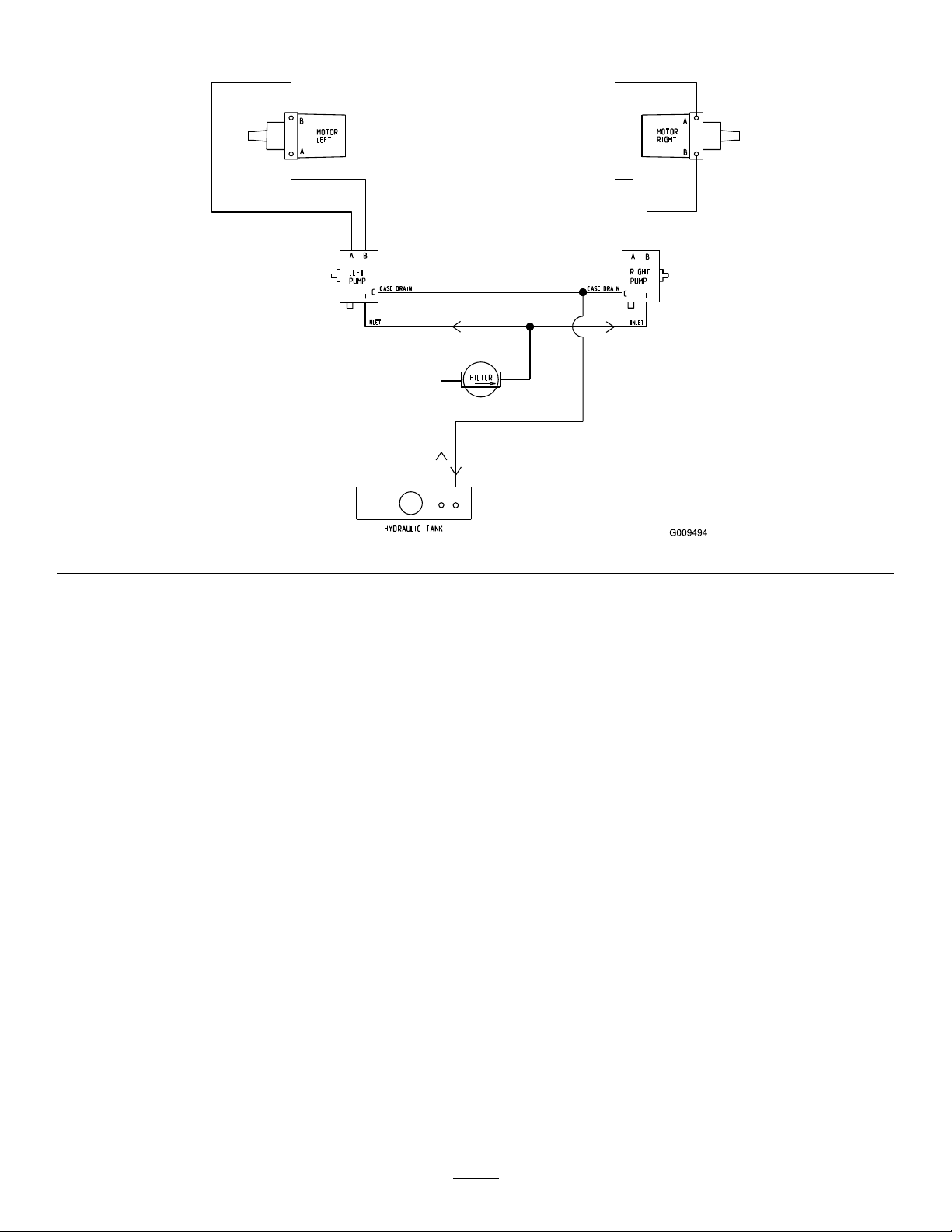
Schematics
HydraulicSchematic(Rev .A)
63
Page 64
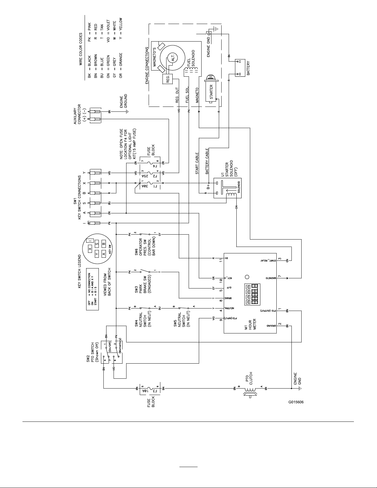
G015606
ElectricalSchematic(Rev .A)
64
Page 65

Notes:
65
Page 66

Notes:
66
Page 67

InternationalDistributorList
Distributor:
AgrolancKft
BalamaPrimaEngineeringEquip.HongKong85221552163
B-RayCorporation
CascoSalesCompany
CeresS.A.CostaRica
CSSCTurfEquipment(pvt)Ltd.SriLanka
CyrilJohnston&Co.
CyrilJohnston&Co.RepublicofIreland
EquiverMexico525553995444ParklandProductsLtd.NewZealand6433493760
FemcoS.A.Guatemala
ForGarderOU
G.Y .K.CompanyLtd.
GeomechanikiofAthensGreece
GolfinternationalTurizm
GuandongGoldenStarChina
HakoGroundandGardenSweden
HakoGroundandGarden
HayterLimited(U.K.)
HydroturfInt.CoDubai
HydroturfEgyptLLC
IrrimacPortugal351212388260T oroEuropeNVBelgium3214562960
IrrigationProductsInt'lPvtLtd.India0091442449
JeanHeybroekb.v.Netherlands31306394611VictusEmakPoland48618238369
Country:
Hungary3627539640
Korea82325512076
PuertoRico7877888383
NorthernIreland442890813121
Estonia3723846060
Japan81726325861
Turkey902163365993Riversa
Norway4722907760
UnitedKingdom441279723444
UnitedArabEmirates97143479479T-MarktLogisticsLtd.Hungary3626525500
Egypt2025194308T oroAustraliaAustralia61395807355
PhoneNumber:Distributor:
5062391138
94112746100
442890813121
5024423277
30109350054
862087651338
4635100000
4387
Country:
MaquiverS.A.Colombia
MaruyamaMfg.Co.Inc.
Mountelda.s.CzechRepublic
Mountelda.s.Slovakia
MunditolS.A.
NormaGarden
OslingerTurfEquipmentSA
OyHakoGroundandGarden
Ab
Perfetto
PratoverdeSRL.
Prochaska&Cie
RTCohen2004Ltd.
LelyTurfcare
SolvertS.A.S.
SpyprosStavrinidesLimitedCyprus
SurgeSystemsIndiaLimited
ValtechMorocco21253766
Japan81332522285
Argentina541 14821
Russia749541 16120
Ecuador59342396970
Finland35898700733
Poland48618208416
Italy390499128
Austria4312785100
Israel97298617979
Spain
Denmark4566109200
France331308177
India911292299901
Phone
Number:
5712364079
420255704
220
420255704
220
9999
128
34952837500
00
35722434131
3636
EuropeanPrivacyNotice
TheInformationT oroCollects
ToroWarrantyCompany(T oro)respectsyourprivacy.Inordertoprocessyourwarrantyclaimandcontactyouintheeventofaproductrecall,weaskyou
tosharecertainpersonalinformationwithus,eitherdirectlyorthroughyourlocalT orocompanyordealer.
TheT orowarrantysystemishostedonserverslocatedwithintheUnitedStateswhereprivacylawmaynotprovidethesameprotectionasapplies
inyourcountry .
BYSHARINGYOURPERSONALINFORMATIONWITHUS,YOUARECONSENTINGTOTHEPROCESSINGOFYOURPERSONALINFORMATION
ASDESCRIBEDINTHISPRIV ACYNOTICE.
TheWayT oroUsesInformation
Toromayuseyourpersonalinformationtoprocesswarrantyclaims,tocontactyouintheeventofaproductrecallandforanyotherpurposewhichwetell
youabout.ToromayshareyourinformationwithT oro'safliates,dealersorotherbusinesspartnersinconnectionwithanyoftheseactivities.Wewillnot
sellyourpersonalinformationtoanyothercompany .Wereservetherighttodisclosepersonalinformationinordertocomplywithapplicablelawsand
withrequestsbytheappropriateauthorities,tooperateoursystemsproperlyorforourownprotectionorthatofotherusers.
RetentionofyourPersonalInformation
Wewillkeepyourpersonalinformationaslongasweneeditforthepurposesforwhichitwasoriginallycollectedorforotherlegitimatepurposes
(suchasregulatorycompliance),orasrequiredbyapplicablelaw .
Toro'sCommitmenttoSecurityofY ourPersonalInformation
Wetakereasonableprecautionsinordertoprotectthesecurityofyourpersonalinformation.Wealsotakestepstomaintaintheaccuracyandcurrent
statusofpersonalinformation.
AccessandCorrectionofyourPersonalInformation
Ifyouwouldliketorevieworcorrectyourpersonalinformation,[email protected].
AustralianConsumerLaw
AustraliancustomerswillnddetailsrelatingtotheAustralianConsumerLaweitherinsidetheboxoratyourlocalT oroDealer.
374-0269RevH
Page 68

TheToroT otalWarranty
Landscape
Contractor
Equipment(LCE)
ConditionsandProductsCovered
TheT oroCompanyanditsafliate,T oroWarrantyCompany ,pursuanttoan
agreementbetweenthem,jointlypromisetotheoriginalpurchasertorepair
theT oroProductslistedbelowifdefectiveinmaterialsorworkmanship.
Thefollowingtimeperiodsapplyfromthedateofpurchasebytheoriginal
owner:
ProductsWarrantyPeriod
WalkBehindMowers
53cmMowers–Residentialuse
53cmMowers–Commercialuse
76cmMowers–Residentialuse
76cmMowers–Commercialuse
Mid-SizeWalk-BehindMowers
•Engine2years
GrandStand
®
Mowers
•Engine2years
•Frame
ZMaster
®
2000SeriesMowers
•Engine2years
•Frame
ZMaster
®
3000SeriesMowers
•Engine2years
•Frame
ZMaster
®
5000and6000Series
Mowers
•Engine2years
•Frame
ZMaster
®
7000SeriesMowers
•Engine2years
•Frame
AllMowers
•Battery2years
•Attachments2years
1
Residentialusemeansuseoftheproductonthesamelotasyourhome.Useatmorethanone
locationisconsideredcommercialuseandthecommercialwarrantywouldapply.
2
SomeenginesusedonT oroLCEProductsarewarrantedbytheenginemanufacturer .
3
Whicheveroccursrst.
4
LifetimeFrameW arranty-Ifthemainframe,consistingofthepartsweldedtogethertoformthe
tractorstructurethatothercomponentssuchastheenginearesecuredto,cracksorbreaksin
normaluse,itwillberepairedorreplacedunderwarrantyatnocostforpartsandlabor.Framefailure
duetomisuseorabuseandfailureorrepairrequiredduetorustorcorrosionarenotcovered.
Thiswarrantyincludesthecostofpartsandlabor,butyoumustpay
transportationcosts.
1
2years
1year
1
2years
1year
2years
2
5yearsor1,200hours
Lifetime(originalowneronly)
4yearsor500hours
2
Lifetime(originalowneronly)
5yearsor1,200hours
2
Lifetime(originalowneronly)
5yearsor1,200hours
2
Lifetime(originalowneronly)
5yearsor1,200hours
2
Lifetime(originalowneronly)
3
4
3
4
3
4
3
4
3
4
InstructionsforObtainingWarrantyService
IfyouthinkthatyourToroProductcontainsadefectinmaterialsor
workmanship,followthisprocedure:
1.Contactyoursellertoarrangeserviceoftheproduct.Ifforanyreason
itisimpossibleforyoutocontactyourseller,youmaycontactany
ToroAuthorizedDistributortoarrangeservice.
2.Bringtheproductandyourproofofpurchase(salesreceipt)tothe
ServiceDealer.
3.IfforanyreasonyouaredissatisedwiththeServiceDealer’s
analysisorwiththeassistanceprovided,contactusat:
RLCCustomerCareDepartment
ToroWarrantyCompany
811 1LyndaleAvenueSouth
Bloomington,MN55420-1196
001-952-948-4707
SeeattachedDistributorList.
OwnerResponsibilities
YoumustmaintainyourToroProductbyfollowingthemaintenance
proceduresdescribedintheOperator'sManual.Suchroutinemaintenance,
whetherperformedbyadealerorbyyou,isatyourexpense.
ItemsandConditionsNotCovered
Thereisnootherexpresswarrantyexceptforspecialemissionsystem
coverageandenginewarrantycoverageonsomeproducts.Thisexpress
warrantydoesnotcoverthefollowing:
•Costofregularmaintenanceserviceorparts,suchaslters,fuel,
lubricants,oilchanges,sparkplugs,airltersbladesharpeningorworn
blades,cable/linkageadjustments,orbrakeandclutchadjustments
•Componentsfailingduetonormalwear
•Anyproductorpartwhichhasbeenalteredormisusedorneglected
andrequiresreplacementorrepairduetoaccidentsorlackofproper
maintenance
•Pickupanddeliverycharges
•RepairsorattemptedrepairsbyanyoneotherthananAuthorizedToro
ServiceDealer
•Repairsnecessaryduetofailuretofollowrecommendedfuel
procedure(consultOperator'sManualformoredetails)
–Removingcontaminantsfromthefuelsystemisnotcovered
–Useofoldfuel(morethanonemonthold)orfuelwhichcontains
morethan10%ethanolormorethat15%MTBE
–Failuretodrainthefuelsystempriortoanyperiodofnon-use
overonemonth
GeneralConditions
Thepurchaseriscoveredbythenationallawsofeachcountry.Therights
towhichthepurchaserisentitledwiththesupportoftheselawsarenot
restrictedbythiswarranty.
374-0272RevC
 Loading...