

Page 1
FormNo.3361-373RevA
GrandStand
™
Mower
witha48inor52inTURBOFORCE
Unit
ModelNo.74558—SerialNo.290000001andUp
ModelNo.74559—SerialNo.290000001andUp
ModelNo.74568—SerialNo.290000001andUp
ModelNo.74569—SerialNo.290000001andUp
ModelNo.79558—SerialNo.290000001andUp
ModelNo.79559—SerialNo.290000001andUp
®
Cutting
Registeratwww.T oro.com.OriginalInstructions(EN)
Page 2
Warning
CALIFORNIA
Proposition65Warning
Theengineexhaustfromthisproduct
containschemicalsknowntotheStateof
Californiatocausecancer,birthdefects,
orotherreproductiveharm.
ThissparkignitionsystemcomplieswithCanadian
ICES-002.
Important:Thisengineisnotequippedwitha
sparkarrestermufer.ItisaviolationofCalifornia
PublicResourceCodeSection4442touseoroperate
theengineonanyforest-covered,brush-covered,or
grass-coveredland.Otherstatesorfederalareas
mayhavesimilarlaws.
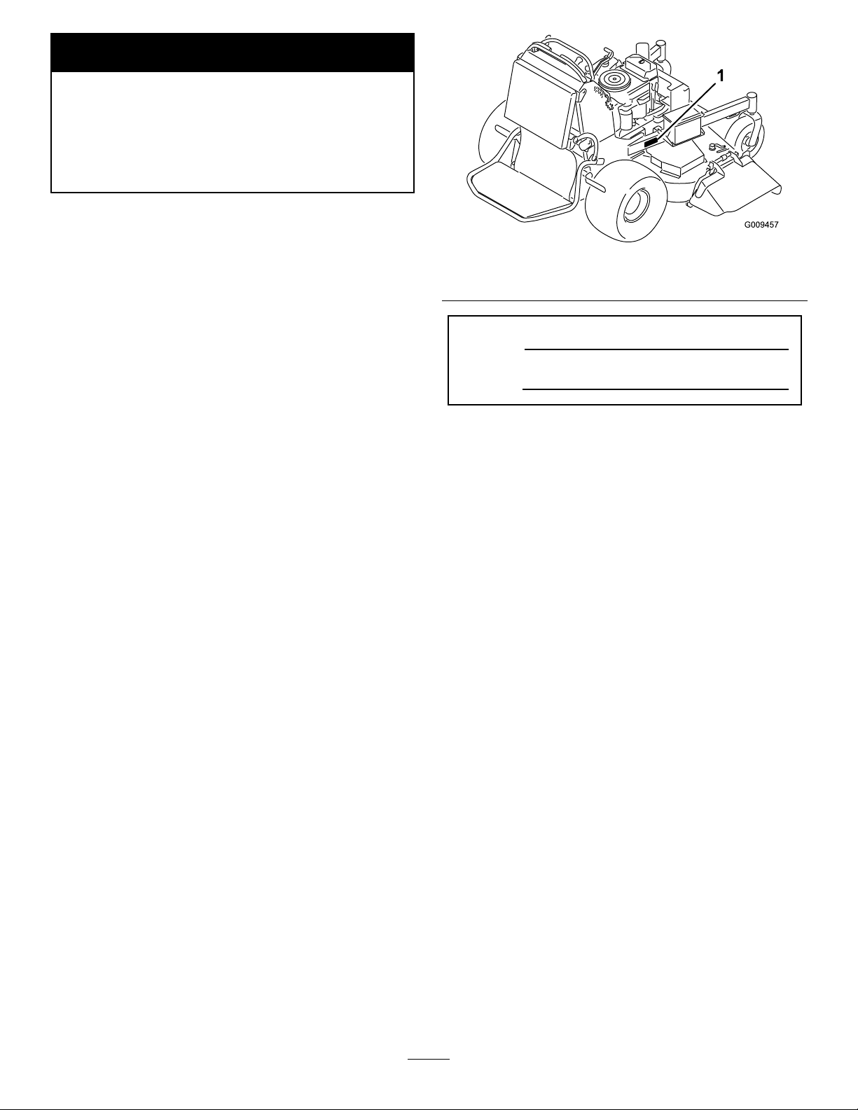
Figure1
1.Locationofthemodelandserialnumbers
ModelNo.
Theenclosed
Engine Owner’ s Man ual
issupplied
forinformationregardingtheUSEnvironmental
ProtectionAgency(EP A)andtheCalifornia
EmissionControlRegulationofemissionsystems,
maintenance,andwarranty.Replacementsmaybe
orderedthroughtheenginemanufacturer.
Introduction
Readthisinformationcarefullytolearnhowtooperate
andmaintainyourproductproperlyandtoavoidinjury
andproductdamage.Youareresponsibleforoperating
theproductproperlyandsafely.
YoumaycontactTorodirectlyatwww .Toro.comfor
productandaccessoryinformation,helpndinga
dealer,ortoregisteryourproduct.
Wheneveryouneedservice,genuineToroparts,or
additionalinformation,contactanAuthorizedService
DealerorToroCustomerServiceandhavethemodel
andserialnumbersofyourproductready.Figure1
identiesthelocationofthemodelandserialnumbers
ontheproduct.Writethenumbersinthespace
provided.
SerialNo.
Thismanualidentiespotentialhazardsandhassafety
messagesidentiedbythefollowingwords:
•Dangersignalsanextremehazardthatwillcause
seriousinjuryordeathifyoudonotfollowthe
recommendedprecautions.
•Warningsignalsahazardthatmaycauseserious
injuryordeathifyoudonotfollowtherecommended
precautions.
•Cautionsignalsahazardthatmaycauseminor
ormoderateinjuryifyoudonotfollowthe
recommendedprecautions.
Thismanualusestwootherwordstohighlight
information.Importantcallsattentiontospecial
mechanicalinformationandNoteemphasizesgeneral
informationworthyofspecialattention.
Contents
Introduction.................................................................2
Safety...........................................................................4
SafeOperatingPractices.......................................4
ToroMowerSafety...............................................5
SlopeChart..........................................................7
SafetyandInstructionalDecals.............................8
ProductOverview......................................................11
Controls.............................................................11
Specications.....................................................12
Operation...................................................................13
AddingFuel.......................................................13
CheckingtheEngineOilLevel............................14
BreakingInaNewMachine................................14
©2008—TheToro®Company
8111LyndaleAvenueSouth
Bloomington,MN55420
Contactusatwww.T oro.com.
2
PrintedintheUSA.
AllRightsReserved
Page 3

ThinkSafetyFirst...............................................14
OperatingtheParkingBrake...............................14
OperatingtheMowerBladeControlSwitch
(PTO)............................................................15
OperatingtheThrottle.......................................15
OperatingtheChoke..........................................15
OperatingtheIgnitionSwitch.............................16
UsingtheSpeedControlLever...........................16
UsingtheFuelShut-OffValve............................16
StartingandStoppingtheEngine........................17
TheSafetyInterlockSystem................................18
OperatingthePlatform......................................19
DrivingForwardorBackward.............................20
StoppingtheMachine.........................................21
PushingtheMachinebyHand.............................21
TransportingMachines.......................................22
LoadingMachines..............................................22
SideDischargingorMulchingtheGrass..............23
AdjustingtheHeight-of-Cut...............................23
AdjustingtheFlowBafe...................................23
PositioningtheFlowBafe.................................24
UsingtheMid-SizeWeight..................................25
Maintenance...............................................................26
RecommendedMaintenanceSchedule(s)................26
PremaintenanceProcedures....................................27
RaisingtheMowerforAccess.............................27
RemovetheCushionforRearAccess..................28
Lubrication.............................................................29
HowtoGrease...................................................29
LubricatingtheMachine.....................................29
EngineMaintenance...............................................30
ServicingtheAirCleaner....................................30
ServicingtheEngineOil.....................................31
ServicingtheSparkPlug.....................................34
FuelSystemMaintenance.......................................35
DrainingtheFuelTank.......................................35
ServicingtheFuelFilter......................................36
ElectricalSystemMaintenance................................36
ServicingtheBattery...........................................36
ServicingtheFuses.............................................38
DriveSystemMaintenance.....................................39
AdjustingtheTracking.......................................39
CheckingtheTirePressure.................................40
AdjustingtheCasterPivotBearing......................40
ServicingtheCasterWheelandBearings.............40
AdjustingtheElectricClutch..............................41
CoolingSystemMaintenance..................................41
CleaningtheAirIntakeScreen............................41
CleaningtheCoolingSystem...............................41
BrakeMaintenance.................................................42
ServicingtheBrake.............................................42
BeltMaintenance....................................................43
ReplacingtheMowerDeckBelt..........................43
ReplacingthePumpDriveBelt...........................44
ControlsSystemMaintenance.................................45
AdjustingtheMotionControlHandle
Positions........................................................45
HydraulicSystemMaintenance...............................47
ServicingtheHydraulicSystem...........................47
MowerDeckMaintenance......................................49
ServicingtheCuttingBlades...............................49
CorrectingtheMowerQualityofCut..................51
ReplacingtheGrassDeector.............................54
Cleaning.................................................................55
CleaningUndertheMower.................................55
WasteDisposal...................................................55
Storage.......................................................................55
CleaningandStorage..........................................55
Troubleshooting.........................................................57
Schematics.................................................................59
3
Page 4

Safety
Note:Theadditionofattachmentsmadeby
othermanufacturersthatdonotmeetAmerican
NationalStandardsInstitutecerticationwillcause
noncomplianceofthismachine.
Improperuseormaintenancebytheoperatororowner
canresultininjury.Toreducethepotentialforinjury,
complywiththesesafetyinstructionsandalwayspay
attentiontothesafetyalertsymbol
CAUTION,W ARNING,orDANGER-“personalsafety
instruction."Failuretocomplywiththeinstructionmay
resultinpersonalinjuryordeath.
SafeOperatingPractices
ThefollowinginstructionsarefromANSIstandard
B71.4-2004.
Training
•ReadtheOperator’sManualandothertraining
material.Iftheoperator(s)ormechanic(s)cannot
readEnglishitistheowner’sresponsibilitytoexplain
thismaterialtothem.
•Becomefamiliarwiththesafeoperationofthe
equipment,operatorcontrols,andsafetysigns.
•Alloperatorsandmechanicsshouldbetrained.The
ownerisresponsiblefortrainingtheusers.
•Neverletchildrenoruntrainedpeopleoperateor
servicetheequipment.Localregulationsmayrestrict
theageoftheoperator.
•Theowner/usercanpreventandisresponsiblefor
accidentsorinjuriesoccurringtohimselforherself,
otherpeopleorproperty.
Preparation
•Evaluatetheterraintodeterminewhataccessories
andattachmentsareneededtoproperlyand
safelyperformthejob.Onlyuseaccessoriesand
attachmentsapprovedbythemanufacturer.
•Wearappropriateclothingincludinghardhat,safety
glassesandhearingprotection.Longhair,loose
clothingorjewelrymaygettangledinmovingparts.
•Inspecttheareawheretheequipmentistobeused
andremoveallobjectssuchasrocks,toysandwire
whichcanbethrownbythemachine.
•Useextracarewhenhandlinggasolineandother
fuels.Theyareammableandvaporsareexplosive.
–Useonlyanapprovedcontainer
,whichmeans
–Neverremovegascaporaddfuelwithengine
running.Allowenginetocoolbeforerefueling.
Donotsmoke.
–Neverrefuelordrainthemachineindoors.
•Checkthatoperator’spresencecontrols,safety
switchesandshieldsareattachedandfunctioning
properly.Donotoperateunlesstheyarefunctioning
properly.
Operation
•Neverrunanengineinanenclosedarea.
•Onlyoperateingoodlight,keepingawayfromholes
andhiddenhazards.
•Besurealldrivesareinneutralandparkingbrakeis
engagedbeforestartingengine.Onlystartengine
fromtheoperator’ sposition.
•Besureofyourfootingwhileusingthismachine,
especiallywhenbackingup.Walk,don’trun.Never
operateonwetgrass.Reducedfootingcouldcause
slipping.
•Slowdownanduseextracareonhillsides.Besure
totravelsidetosideonhillsides.Turfconditions
canaffectthemachine’sstability .Usecautionwhile
operatingneardrop-offs.
•Slowdownandusecautionwhenmakingturnsand
whenchangingdirectionsonslopes.
•Neverraisedeckwiththebladesrunning.
•NeveroperatewiththePTOshield,orotherguards
notsecurelyinplace.Besureallinterlocksare
attached,adjustedproperly,andfunctioningproperly .
•Neveroperatewiththedischargedeectorraised,
removedoraltered,unlessusingagrasscatcher.
•Donotchangetheenginegovernorsettingor
overspeedtheengine.
•Stoponlevelground,disengagedrives,engage
parkingbrake(ifprovided),shutoffenginebefore
leavingtheoperator’spositionforanyreason
includingemptyingthecatchersoruncloggingthe
chute.
•Stopequipmentandinspectbladesafterstriking
objectsorifanabnormalvibrationoccurs.Make
necessaryrepairsbeforeresumingoperations.
•Keephandsandfeetawayfromthecuttingunit.
•Lookbehindanddownbeforebackinguptobesure
ofaclearpath.
•Keeppetsandbystandersaway.
•Slowdownandusecautionwhenmakingturnsand
crossingroadsandsidewalks.Stopbladesifnot
mowing.
4
Page 5

•Beawareofthemowerdischargedirectionanddo
notpointitatanyone.
•Donotoperatethemowerundertheinuenceof
alcoholordrugs.
Thisproductisdesignedforcuttingandrecyclinggrass
or,whenequippedwithagrassbagger,forcatching
cutgrass.Anyuseforpurposesotherthanthesecould
provedangeroustouserandbystanders.
•Usecarewhenloadingorunloadingthemachine
intoorfromatrailerortruck.
•Usecarewhenapproachingblindcorners,shrubs,
trees,orotherobjectsthatmayobscurevision.
Maintenanceandstorage
•Disengagedrives,setparkingbrake,stopengineand
removekeyordisconnectsparkplugwire.Waitfor
allmovementtostopbeforeadjusting,cleaningor
repairing.
•Cleangrassanddebrisfromcuttingunit,drives,
mufers,andenginetohelppreventres.Cleanup
oilorfuelspillage.
•Letenginecoolbeforestoringanddonotstorenear
ame.
•Shutofffuelwhilestoringortransporting.Donot
storefuelnearamesordrainindoors.
•Parkmachineonlevelground.Setparkingbrake.
Neverallowuntrainedpersonneltoservicemachine.
•Usejackstandstosupportcomponentswhen
required.
GeneralOperation
•Besuretheareaisclearofotherpeoplebefore
mowing.Stopthemachineifanyoneentersthearea.
•Donottouchequipmentorattachmentpartswhich
maybehotfromoperation.Allowtocoolbefore
attemptingtomaintain,adjustorservice.
•UseonlyToroapprovedattachments.Warrantymay
bevoidedifusedwithunapprovedattachments.
•Checkcarefullyforoverheadclearances(i.e.
branches,doorways,electricalwires)before
operatingunderanyobjectsanddonotcontact
them.
•Slowdownbeforemakingturnsanduseextra
caution.
•Usecautionwhenridingtheplatformovercurbs,
rocks,roots,orotherobstructions.
•Lookbehindanddownbeforebackinguptobesure
ofaclearpath.Useextracarewhenoperationin
reverse.
•Neverjerkthecontrols;useasteadymotion.
•Carefullyreleasepressurefromcomponentswith
storedenergy.
•Disconnectthebatteryorremovesparkplugwire
beforemakinganyrepairs.Disconnectthenegative
terminalrstandthepositivelast.Reconnectthe
positiverstandnegativelast.
•Usecarewhencheckingblades.Wraptheblade(s)or
weargloves,andusecautionwhenservicingthem.
Onlyreplaceblades.Neverstraightenorweldthem.
•Keephandsandfeetawayfrommovingparts.If
possible,donotmakeadjustmentswiththeengine
running.
•Keepallpartsingoodworkingconditionandall
hardwaretightened.Replaceallwornordamaged
decals.
ToroMowerSafety
Thefollowinglistcontainssafetyinformationspecic
toT oroproductsandothersafetyinformationyoumust
know .
Thisproductiscapableofamputatinghandsand
feetandthrowingobjects.Alwaysfollowallsafety
instructionstoavoidseriousinjuryordeath.
SlopeOperation
Allslopesandrampsrequireextracaution.Ifyoufeel
uneasyonaslope,donotmowit.
•Removeobstaclessuchasrocks,treelimbs,etc.from
themowingarea.
•Watchforholes,rutsorbumps.Tallgrasscanhide
obstacles.
•Usecautionneardrop-offs,ditches,orembankments.
Themachinecouldsuddenlyturnoverifawheel
goesovertheedgeofaclifforditch,orifanedge
cavesin.
•Useextracarewithgrasscatchersorother
attachments.Thesecanchangethestabilityofthe
machine.
•Keepallmovementonslopesslowandgradual.Do
notmakesuddenchangesinspeedordirection.
•Mowslopessidetoside.
•Donotmowslopesgreaterthan20degrees.
Service
•Neverstorethemachineorfuelcontainerinside
wherethereisanopename,suchasnearawater
heaterorfurnace.
5
Page 6

•Keepnutsandboltstight,especiallytheblade
attachmentbolts.Keepequipmentingood
condition.
•Nevertamperwithsafetydevices.Checksafety
systemsforproperoperationbeforeeachuse.
•Useonlygenuinereplacementpartstoensurethat
originalstandardsaremaintained.
•Checkbrakeoperationfrequently.Adjustandservice
asrequired.
6
Page 7
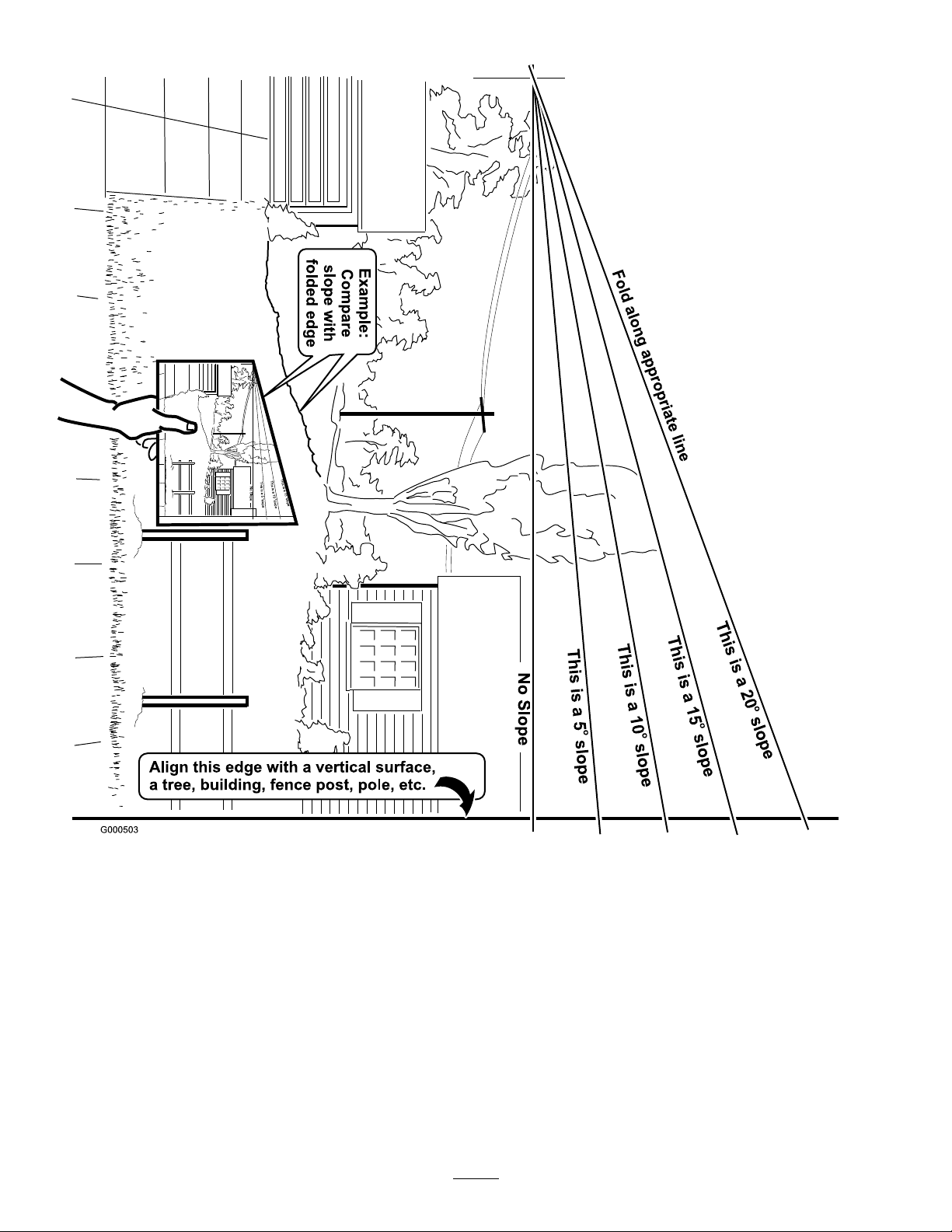
SlopeChart7SafetyandInstructional
Decals
Page 8
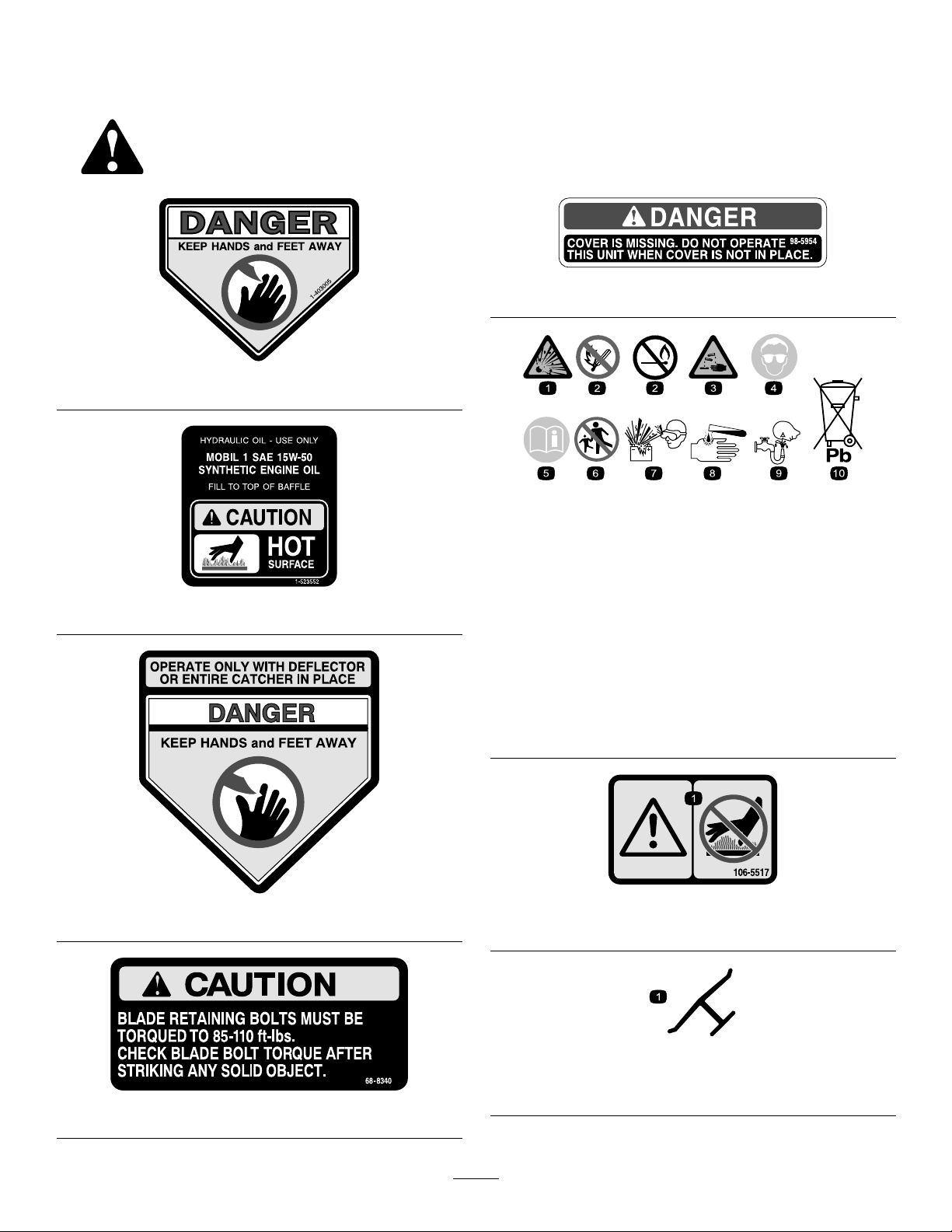
Safetydecalsandinstructionsareeasilyvisibletotheoperatorandarelocatednearanyareaof
potentialdanger.Replaceanydecalthatisdamagedorlost.
98-5954
1-403005
BatterySymbols
Someorallofthesesymbolsareonyourbattery
1.Explosionhazard
2.Nore,opename,or
1-523552
smoking.
3.Causticliquid/chemical
burnhazard
4.Weareyeprotection9.Flusheyesimmediately
5.ReadtheOperator’s
Manual.
6.Keepbystandersasafe
distancefromthebattery.
7.Weareyeprotection;
explosivegasescan
causeblindnessandother
injuries
8.Batteryacidcancause
blindnessorsevereburns.
withwaterandgetmedical
helpfast.
10.Containslead;donot
discard.
54-9220
1.Warning—donottouchthehotsurface.
106-5517
Manufacturer’sMark
1.Indicatesthebladeisidentiedasapartfromtheoriginal
machinemanufacturer.
68-8340
8
Page 9
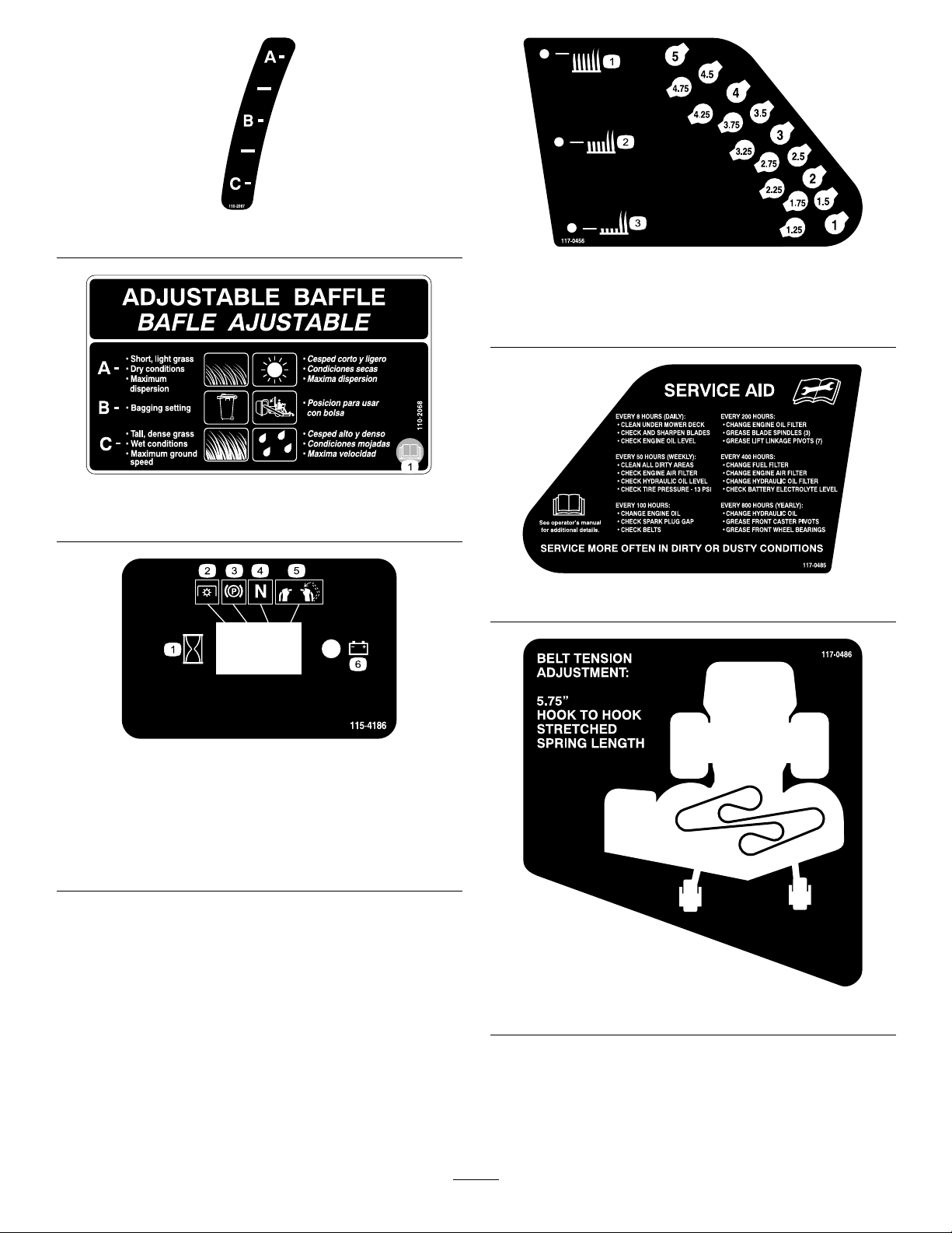
110-2067
110-2068
1.ReadtheOperator’sManual.
117-0456
1.Heightofcut(HOC)—high3.Heightofcut(HOC)—low
2.Heightofcut
(HOC)—medium
117-0485
1.Interval
2.PowerTake-off(PTO)
3.Parkingbrake
4.Neutral
5.Operatorpresenceswitch
6.Battery
115-4186
117-0486
9
Page 10
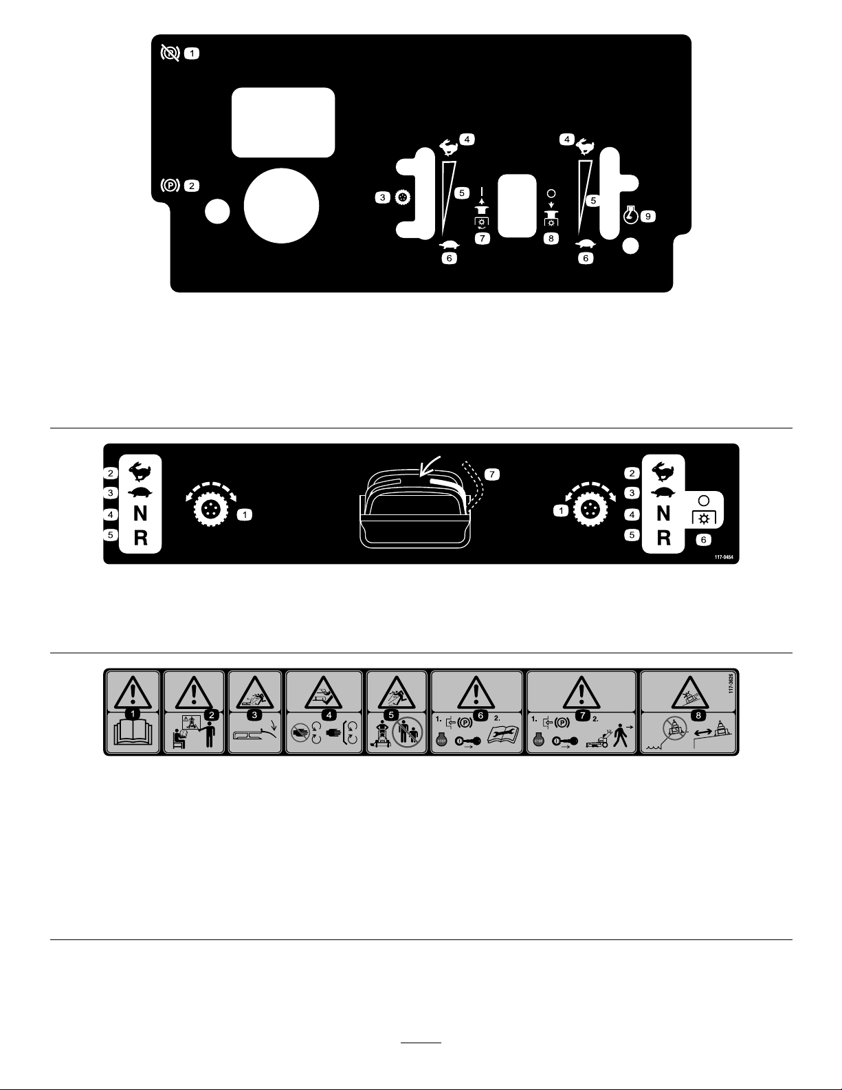
117-0453
1.Parkingbrake—disengage5.Fast
2.Parkingbrake—engage
3.Choke7.Slow11.Heightofcut(HOC)—low
4.Speedcontrollever8.PowerTake-off
6.Continuousvariablesetting
(PTO)—engage
9.PowerTake-off
10.Enginespeed
12.Heightofcut
117-0454
1.Tractioncontrol
2.Fast4.Neutral
3.Slow
5.Reverse
6.PowerTake-off
(PTO)—disengage
13.Heightofcut(HOC)—high
(HOC)—medium
7.Operatorpresenceswitch
(PTO)—disengage
117–3626
1.Warning—readtheOperator’sManual.5.Thrownobjecthazard—keepbystandersasafedistancefrom
2.Warning—donotoperatethismachineunlessyouaretrained.6.Warning—engagetheparkingbrake,stoptheengine
3.Thrownobjecthazard—keepdeectorinplace.
4.Cutting,dismembermenthazardofhandorfoot—stayaway
frommovingpartsandkeepallguardsandshieldsinplace.
themachine.
andremovethesparkplugwirebeforeperformingany
maintenanceonthemachine.
7.Warning—engagetheparkingbrakeandstoptheengine
beforeleavingthemachine.
8.Slidingandlossofcontrolhazard—donotoperatethe
machineneardrop-offsorwater;keepasafedistancefrom
drop-offs.
10
Page 11
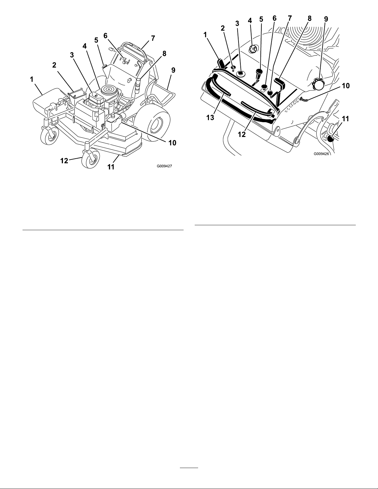
ProductOverview
Figure2
1.Sidedischargechute7.Controllevers
2.Battery8.Manualtube
3.Engine
4.Fuelshut-offvalve
5.Fueltank11.Mowerdeck
6.Controls
9.Platform(downposition)
10.Hydraulictank
12.Frontcasterwheel
Figure3
1.Parkingbrakelever
2.Choke
3.Ignitionswitch
4.Fuelguage
5.Speedcontrollever
6.Bladecontrolswitch(PTO)13.Leftmotioncontrollever
7.Throttlecontrol
8.Height-of-cutlever
9.Fuelcap
10.Height-of-cutpin
11.Platformlatch
12.Rightmotioncontrollever
Controls
Becomefamiliarwithallthecontrols(Figure3)before
youstarttheengineandoperatethemachine.
HourMeter
Thehourmeterrecordsthenumberofhourstheengine
hasoperated.Itoperateswhentheengineisrunning.
Usethesetimesforschedulingregularmaintenance
(Figure4).
FuelGauge
Thefuelgaugeislocatedonthetopleftsideofthetank
(Figure3).
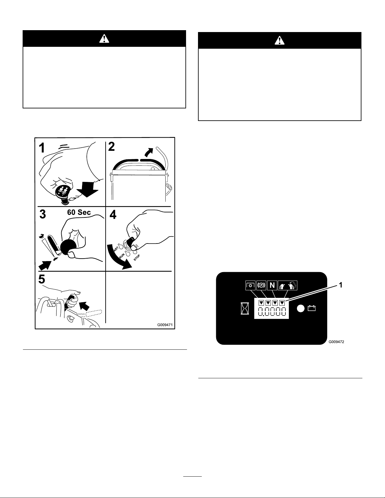
SafetyInterlockIndicators
Therearesymbolsonthehourmeterandindicatewith
ablacktrianglethattheinterlockcomponentisinthe
correctposition(Figure4).
BatteryIndicatorLight
IftheignitionkeyisturnedtotheOnpositionforafew
seconds,thebatteryvoltagewillbedisplayedinthearea
wherethehoursarenormallydisplayed.
Thebatterylightturnsonwhentheignitionisturned
onandwhenthechargeisbelowthecorrectoperating
level(Figure4).
11
Page 12
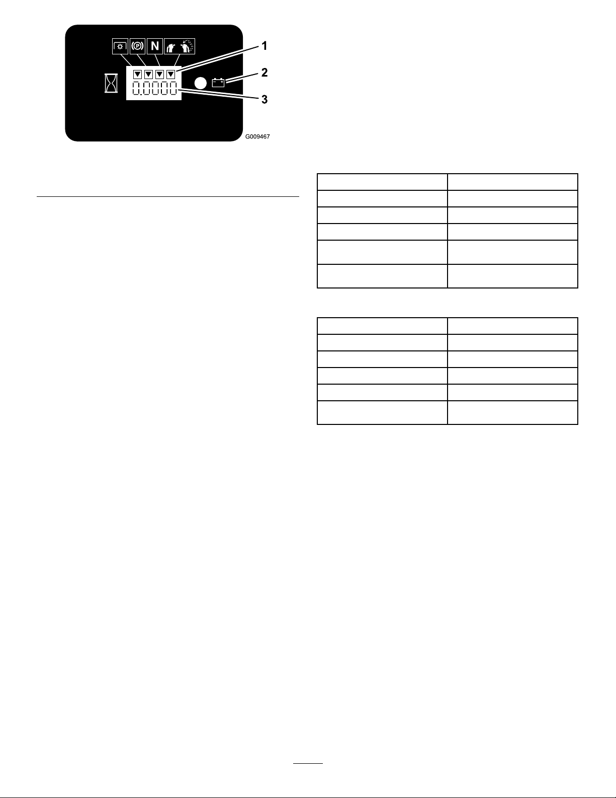
Figure4
1.Safetyinterlocksymbols
2.Batterylight
3.Hourmeter
SpeedControlLever
Thismachinehasavariablespeedcontrol.Thiscontrols
howfastorslowthemachinewilltravel.
ThrottleControl
enhanceandexpanditscapabilities.Contactyour
AuthorizedServiceDealerorDistributororgoto
www.Toro.comforalistofallapprovedattachments
andaccessories.
Specications
Note:Specicationsanddesignaresubjecttochange
withoutnotice.
48inchmowers:
Widthwithdeectordown63.5inches(161.3cm)
Lengthwithplatformdown74inches(188cm)
Lengthwithplatformup58inches(147.3cm)
Height
Weightwith19hpengine
Weightwith23hpengine
48inches(121.9cm)
881(399.6kg)
888(402.8kg)
ThethrottlecontrolisvariablebetweenFastandSlow.
Choke
Usethechoketostartacoldengine.
BladeControlSwitch(PTO)
Thebladecontrolswitch(PTO)isusedtoengage
theelectricclutchtodrivethemowerbladeswiththe
rightsidemotioncontrolleverinthecenter,un-locked
position.Pulltheswitchuptoengagethebladesand
release.Todisengagetheblades,pushthebladecontrol
switch(PTO)downormoveorreleasetherightside
motioncontrolleverintotheneutrallockposition.
IgnitionSwitch
Thisswitchisusedtostartthemowerengineandhas
threepositions:Off,RunandStart.
MotionControlLevers
Themotioncontrolleversareusedtodrivethemachine
forward,reverse,andturneitherdirection.
52inchmowers:
Widthwithdeectordown67.5inches(171.4cm)
Lengthwithplatformdown74inches(188cm)
Lengthwithplatformup58inches(147.3cm)
Height
Weightwith19hpengine
Weightwith23hpengine
48inches(121.9cm)
883(400.5kg)
900(408.2kg)
FuelShut-offValve
Closethefuelshut-offvalve(ontherightsideofthe
engine)whentransportingorstoringthemower.
Attachments/Accessories
AselectionofToroapprovedattachmentsand
accessoriesareavailableforusewiththemachineto
12
Page 13

Operation
AddingFuel
UseUnleadedRegularGasolinesuitablefor
automotiveuse(85pumpoctaneminimum).Leaded
regulargasolinemaybeusedifunleadedregularisnot
available.
Important:Neverusemethanol,gasoline
containingmethanol,orgasoholcontainingmore
than10%ethanolbecausethefuelsystemcouldbe
damaged.Donotmixoilwithgasoline.
Incertainconditions,gasolineisextremely
ammableandhighlyexplosive.Areor
explosionfromgasolinecanburnyouand
othersandcandamageproperty.
•Fillthefueltankoutdoors,inanopenarea,
whentheengineiscold.Wipeupany
gasolinethatspills.
•Neverllthefueltankinsideanenclosed
trailer.
•Donotllthefueltankcompletelyfull.Add
gasolinetothefueltankuntilthelevelis1
inch(25mm)belowthebottomoftheller
neck.Thisemptyspaceinthetankallows
gasolinetoexpand.
Incertainconditionsduringfueling,static
electricitycanbereleasedcausingaspark
whichcanignitethegasolinevapors.Are
orexplosionfromgasolinecanburnyouand
othersandcandamageproperty.
•Alwaysplacegasolinecontainersonthe
groundawayfromyourvehiclebeforelling .
•Donotllgasolinecontainersinsidea
vehicleoronatruckortrailerbedbecause
interiorcarpetsorplastictruckbedliners
mayinsulatethecontainerandslowtheloss
ofanystaticcharge.
•Whenpractical,removegas-powered
equipmentfromthetruckortrailerand
refueltheequipmentwithitswheelsonthe
ground.
•Ifthisisnotpossible,thenrefuelsuch
equipmentonatruckortrailerfroma
portablecontainer,ratherthanfroma
gasolinedispensernozzle.
•Ifagasolinedispensernozzlemustbeused,
keepthenozzleincontactwiththerimof
thefueltankorcontaineropeningatall
timesuntilfuelingiscomplete.
•Neversmokewhenhandlinggasoline,and
stayawayfromanopenameorwhere
gasolinefumesmaybeignitedbyaspark.
•Storegasolineinanapprovedcontainerand
keepitoutofthereachofchildren.Never
buymorethana30-daysupplyofgasoline.
•Donotoperatewithoutentireexhaust
systeminplaceandinproperworking
condition.
Gasolineisharmfulorfatalifswallowed.
Long-termexposuretovaporscancauseserious
injuryandillness.
•Avoidprolongedbreathingofvapors.
•Keepfaceawayfromnozzleandgastankor
conditioneropening.
•Keepgasawayfromeyesandskin.
UsingStabilizer/Conditioner
Useafuelstabilizer/conditionerinthemachineto
providethefollowingbenets:
•Keepsgasolinefreshduringstorageof90daysor
less.Forlongerstorageitisrecommendedthatthe
fueltankbedrained.
•Cleanstheenginewhileitruns
•Eliminatesgum-likevarnishbuildupinthefuel
system,whichcauseshardstarting
13
Page 14
Important:Donotusefueladditives
containingmethanolorethanol.
Addthecorrectamountofgas
stabilizer/conditionertothegas.
Note:Afuelstabilizer/conditionerismost
effectivewhenmixedwithfreshgasoline.To
minimizethechanceofvarnishdepositsinthefuel
system,usefuelstabilizeratalltimes.
BreakingInaNewMachine
Newenginestaketimetodevelopfullpower.Mower
decksanddrivesystemshavehigherfrictionwhennew,
placingadditionalloadontheengine.Allow40to50
hoursofbreak-intimefornewmachinestodevelopfull
powerandbestperformance.
ThinkSafetyFirst
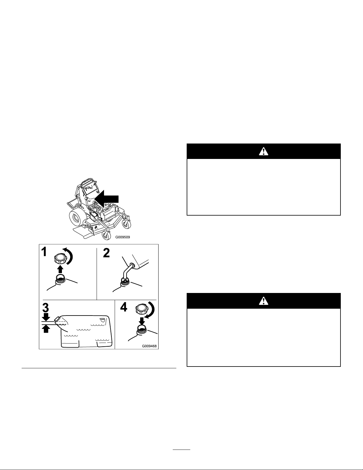
FillingtheFuelTank
Note:Donotllthefueltankcompletelyfull.Add
gasolinetothefueltankuntilthelevelis1inch(25mm)
belowthebottomofthellerneck.Thisemptyspace
inthetankallowsgasolinetoexpand.
1.Shuttheengineoffandsettheparkingbrake.
2.Cleanaroundthefueltankcap.
3.Fillthefueltank.Ensurethereisspacebelowthe
llerneckasshowninFigure5.
Carefullyreadallthesafetyinstructionsanddecalsin
thesafetysection.Knowingthisinformationcould
helpyouoranybystandersavoidinjury.
Theuseofprotectiveequipmentforeyes,hearing,feet
andheadisrecommended.
Thismachineproducessoundlevelsinexcess
of85dBAattheoperator’searandcancause
hearinglossthroughextendedperiodsof
exposure.
Wearhearingprotectionwhenoperatingthis
machine.
OperatingtheParkingBrake
Alwayssettheparkingbrakewhenyoustopthe
machineorleaveitunattended.Beforeeachuse,check
theparkingbrakeforproperoperation.
Figure5
CheckingtheEngineOilLevel
Beforeyoustarttheengineandusethemachine,check
theoillevelintheenginecrankcase;refertoChecking
OilLevelinEngineMaintenance.
Note:Determinetheleftandrightsidesofthe
machinefromthenormaloperatingposition.
Iftheparkingbrakedoesnotholdsecurely,adjustit.
RefertoServicingtheParkingBrake.
Childrenorbystandersmaybeinjuredifthey
moveorattempttooperatethemachinewhile
itisunattended.
Alwaysremovetheignitionkeyandsetthe
parkingbrakewhenleavingthemachine
unattended,evenifjustforafewminutes.
SettingtheParkingBrake
Pulltheparkingbrakeleverrearwardandoverinto
engagedposition(Figure6).
14
Page 15
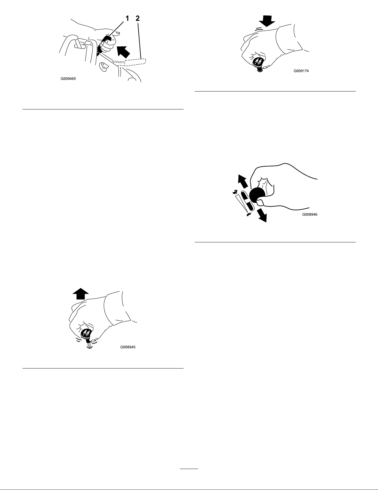
Figure6
G008945
G009174
G008946
1.Parkingbrakeengaged2.Parkingbrakereleased
Figure8
OperatingtheThrottle
ReleasingtheParkingBrake
Pullthebrakeleverbackandoverintotheslotand
pushtheparkingbrakeleverforward.
OperatingtheMowerBlade
ControlSwitch(PTO)
Thebladecontrolswitch(PTO)isusedinconjunction
withtherightsidemotioncontrollevertoengageand
disengagethemowerblades.
EngagingtheMowerBlades(PTO)
1.Toengagethemowerblades,movetherightside
motioncontrollevertothecenter,un-locked
position.
2.Pullthebladecontrolswitch(PTO)upandrelease
itwhileholdingdowntherightsidemotioncontrol
leverinthecenter,un-lockedposition.
ThethrottlecontrolcanbemovedbetweenFastand
Slowpositions(Figure9).
Alwaysusethefastpositionwhenturningonthe
mowerdeckwiththebladecontrolswitch(PTO).
Figure9
OperatingtheChoke
Usethechoketostartacoldengine.
1.Iftheengineiscold,usethechoketostartthe
engine.
Figure7
DisengagingtheMowerBlades(PTO)
Thefollowingaretwooptionsfordisengagingthe
mowerblades.
•Pushthebladecontrolswitch(PTO)downtothe
offposition.
•Movethemotioncontrolleverstoneutralandmove
therightsidemotioncontrolleverintotheneutral
lockposition.
2.Pulluponthechokeknobtoengagethechoke
beforeusingtheignitionswitch(Figure10).
3.Pushdownonthechoketodisengagethechoke
aftertheenginehasstarted(Figure10).
15
Page 16
G008959
1
2
Figure10
START
RUN
STOP
G008947
1.On2.Off
UsingtheSpeedControl
Lever
Thismachinehasaspeedcontrolleverthatsetsthe
speedofthemachine.Thiscanbeadjustedtothe
operator’sdesiredspeed.Itisrecommendedtousethe
slowestspeedfornewoperator’s.
1.Movethespeedcontrollevertosetthedesired
speed.
2.Movethecontrolleverstodrivethemachine.The
controlleversmaybepushedforwardtothefront
referencebarwhilethespeedofthemachineis
controlledbythespeedcontrollever.
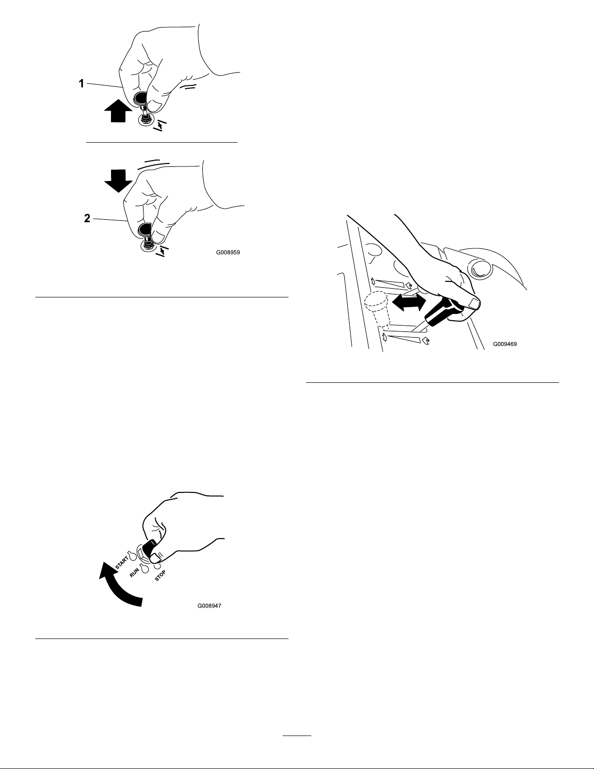
OperatingtheIgnitionSwitch
1.TurntheignitionkeytotheStartposition
(Figure11).Whentheenginesstarts,releasethekey.
Important:Donotengagestarterformore
than5secondsatatime.Iftheenginefails
tostartallowa15secondcool-downperiod
betweenattempts.Failuretofollowthese
instructionscanburnoutthestartermotor.
Note:Additionalstartingcyclesmayberequired
whenstartingtheengineforthersttimeafterthe
fuelsystemhasbeenwithoutfuelcompletely.
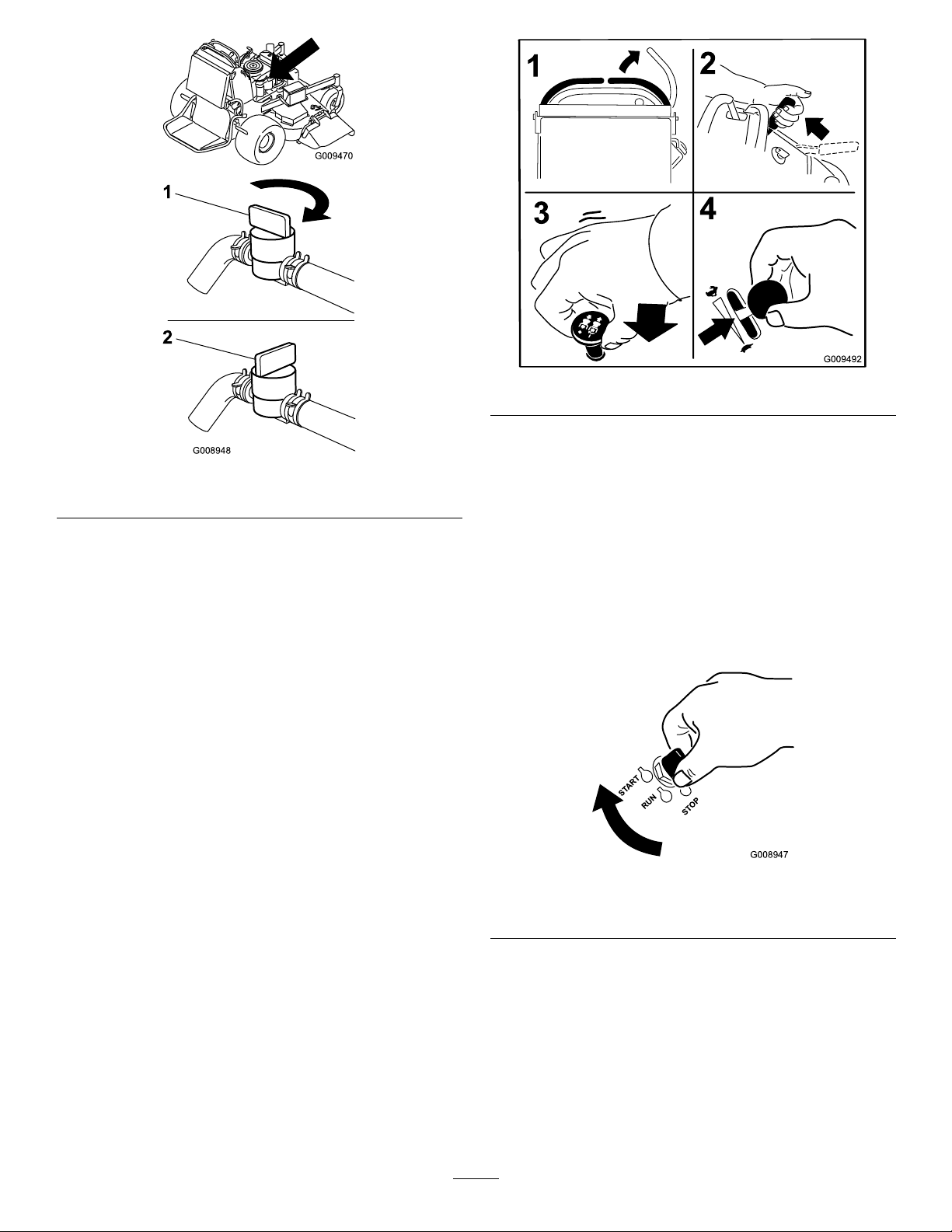
UsingtheFuelShut-OffValve
Closethefuelshut-offvalvefortransport,maintenance,
andstorage(Figure13).
Ensurethefuelshut-offvalveisopenwhenstarting
theengine.
Figure12
Figure11
2.Turntheignitionkeytostoptostoptheengine.
16
Page 17
G008948
1
2
Figure13
START
RUN
STOP
G008947
1.On2.Off
StartingandStoppingthe
Engine
StartingtheEngine
1.Connectthewirestothesparkplugs.
2.Openthefuelvalve.
3.Movetherightmotioncontrollevertoneutral
lockedposition.
4.Settheparkingbrake;refertoSettingtheParking
Brake.
Figure14
7.TurntheignitionkeytotheStartposition
(Figure11).Whentheenginesstarts,releasethekey.
Important:Donotengagestarterformore
than5secondsatatime.Iftheenginefails
tostartallowa15secondcool-downperiod
betweenattempts.Failuretofollowthese
instructionscanburnoutthestartermotor.
Note:Additionalstartingcyclesmayberequired
whenstartingtheengineforthersttimeafterthe
fuelsystemhasbeenwithoutfuelcompletely.
5.Movethebladecontrolswitch(PTO)totheOff
position.
Figure15
6.MovethethrottlelevermidwaybetweentheSlow
andFastpositions.
1.Off3.Start
2.Run
Note:Awarmorhotenginemaynotrequire
choking.
17
Page 18
StoppingtheEngine
TheSafetyInterlockSystem
Childrenorbystandersmaybeinjuredifthey
moveorattempttooperatethetractorwhileit
isunattended.
Alwaysremovetheignitionkeyandsetthe
parkingbrakewhenleavingthemachine
unattended,evenifjustforafewminutes.
Lettheengineidleatslowthrottle(turtle)for60
secondsbeforeturningtheignitionswitchoff.
Ifsafetyinterlockswitchesaredisconnected
ordamagedthemachinecouldoperate
unexpectedlycausingpersonalinjury.
•Donottamperwiththeinterlockswitches.
•Checktheoperationoftheinterlock
switchesdailyandreplaceanydamaged
switchesbeforeoperatingthemachine.
UnderstandingtheSafetyInterlock
System
Thesafetyinterlocksystemisdesignedtopreventthe
mowerbladesfromrotatingunless:
•Therightsidemotioncontrolleverismovedtothe
center,un-lockedposition.
•Thebladecontrolswitch(PTO)ispulledon.
Thesafetyinterlocksystemisdesignedtostopthe
mowerbladesifyoumoveorreleasetherightside
motioncontrolleverintotheneutrallockposition.
Figure16
Important:Makesurefuelshutoffvalveisclosed
beforetransportingorstoringthemachine,asfuel
leakagemayoccur.Beforestoringthemachine,
pullwireoffsparkplug(s)topreventpossibilityof
accidentalstarting.
Thehourmeterhassymbolstonotifytheuserwhen
theinterlockcomponentisinthecorrectposition.
Whenthecomponentisinthecorrectposition,a
trianglewilllightupinthecorrespondingsquare.
Figure17
1.Triangleslightupwhentheinterlockcomponentsareinthe
correctposition
TestingtheSafetyInterlockSystem
ServiceInterval:Beforeeachuseordaily
Testthesafetyinterlocksystembeforeyouusethe
machineeachtime.
Note:Ifthesafetysystemdoesnotoperateas
describedbelow ,haveanAuthorizedServiceDealer
repairthesafetysystemimmediately.
18
Page 19

1.Starttheengine;refertoStartingandStoppingthe
EngineinOperation,page13.
2.Settheparkingbrake.
3.Movetherightsidemotioncontrollevertothe
center,un-lockedposition.Thebladesshould
notrotate.
4.Movethemotioncontrolleversforward.The
engineshouldkill.
5.Starttheengineandreleasetheparkingbrake.
6.Movetherightsidemotioncontrollevertothe
center,un-lockedposition.
7.Continueholdingtherightsidemotioncontrollever
inthecenter,un-lockedpositionandpulluponthe
bladecontrolswitch(PTO)andrelease.Theclutch
shouldengageandthemowerbladesbeginrotating.
8.Moveorreleasetherightsidemotioncontrollever
intotheneutrallockposition.Thebladesshould
stoprotatingandtheenginecontinuestorun.
9.Pushthebladecontrolswitchdownandmove
therightsidemotioncontrollevertothecenter,
un-lockedposition.
10.Continueholdingtherightsidemotioncontrollever
inthecenter,un-lockedpositionandpulluponthe
bladecontrolswitch(PTO)andrelease.Theclutch
shouldengageandthemowerbladesbeginrotating.
11.Pushthebladecontrolswitch(PTO)downtothe
offposition.Thebladesshouldstoprotating.
12.Withtheenginerunning,pullupthebladecontrol
switch(PTO)andreleasewithoutholdingright
sidemotioncontrollevertothecenter,un-locked
position.Thebladesshouldnotrotate.
OperatingthePlatform
Themachinecanbeusedwiththeplatformintheup
ordownposition.Itistheoperator’spreferenceon
whichpositiontouse.
OperatingtheMachinewiththe
PlatformUp
Operatingthemachinewiththeplatformupis
recommendedwhen:
•Mowingneardrop-off’s
•Mowingsmallareaswherethemachineistoolong
•Areaswithlowoverhangingbranchesorobstacles
•Loadingthemachinefortransport
•Drivingupslopes
Toraisetheplatform,pullthebackoftheplatformup
sothelatchpinandknoblockitintoplace.Pushittight
againstthecushionforthelatchpintolockintoplace.
OperatingtheMachinewiththe
PlatformDown
Operatingthemachinewiththeplatformdownis
recommendedwhen:
•Mowingmostareas
•Drivingdownslopes
Tolowertheplatform,pushtheplatformforward
againstthecushiontoreleasepressureonthelatchpin
andthenpulltheknoboutandlowertheplatform.
Theoperatorplatformisheavyandmaycause
injurywhenloweringandraisingtheoperator
platform.Theplatformmaysuddenlydropif
notsupportedwhenthelatchpinispulledout.
•Donotputyourhandsorngersinthe
platformpivotareawhenloweringorraising
theoperatorplatform.
•Makesuretheplatformissupportedwhen
thelatchpinispulledout.
•Makesurethelatchsecurestheplatform
whenfoldingitintheupposition.Pushit
tightagainstthecushionforthelatchpinto
lockintoplace.
19
Page 20
2.Movetherightsidemotioncontrollevertothe
center,un-lockedposition.
Figure19
1.Frontreferencebar
2.Leftcontrollever
3.Rearreferencebar
4.Rightcontrollever
5.Rightcontrolleverinthe
neutrallockposition
Figure18
1.Platformup
2.Platformdown
3.Pulltheknobouttolower
theplatform
DrivingForwardorBackward
Thethrottlecontrolregulatestheenginespeedas
measuredinrpm(revolutionsperminute).Place
thethrottlecontrolinthefastpositionforbest
performance.Alwaysoperateinthefullthrottle
positionwhenmowing.
Machinecanspinveryrapidly.Operatormay
losecontrolofmachineandcausepersonal
injuryordamagetomachine.
Slowthemachinedownbeforemakingsharp
turns.
3.Togoforward,movethespeedcontrollevertothe
desiredspeed.
4.Slowlypushthemotioncontrolleversforward
(Figure20).
Note:Theenginewillkilliftherighthandcontrol
leverismovedwiththeparkingbrakeengaged.
Thefartheryoumovethetractioncontrolleversin
eitherdirection,thefasterthemachinewillmovein
thatdirection.
Tostop,pullthemotioncontrolleversbacktothe
neutralposition.
DrivingForward
1.Releasetheparkingbrake;refertoReleasingthe
ParkingBrakeinOperation.
20
Page 21

Figure20
Settheparkingbrakewhenyouleavethemachine;refer
toSettingtheParkingBrakeinOperation,page13.
Remembertoremovethekeyfromtheignitionswitch.
Childrenorbystandersmaybeinjuredifthey
moveorattempttooperatethetractorwhileit
isunattended.
Alwaysremovetheignitionkeyandsetthe
parkingbrakewhenleavingthemachine
unattended,evenifjustforafewminutes.
PushingtheMachinebyHand
Theby-passvalvesallowthemachinetobepushedby
handwithouttheenginerunning.
Important:Alwayspushthemachinebyhand.
Nevertowthemachinebecausehydraulicdamage
mayoccur.
DrivingBackward
1.Movetherightsidemotioncontrollevertothe
center,un-lockedposition.
2.Slowlypullthemotioncontrolleversrearward
(Figure21).
Figure21
ToPushtheMachine
1.DisengagethePTO,movethemotioncontrol
leverstotheneutrallockedpositionandsetthe
parkingbrake.
2.Opentheby-passvalveonbothpumpsbyturning
themcounterclockwise1to2turns.Thisallows
hydraulicuidtoby-passthepumpsandthewheels
toturn(Figure22).
Note:Rotatetheby-passvalvesamaximumof2
turnssothevalvedoesnotcomeoutofthebody
causinguidtorunout.
StoppingtheMachine
Tostopthemachine,movethemotioncontrolleversto
neutral,movetherightsidemotioncontrolleverinto
theneutrallockposition,disengagethepowertakeoff
(PTO),andturntheignitionkeytooff.
Figure22
1.Pumpby-passvalve
21
Page 22

3.Releasetheparkingbrake.
4.Pushthemachinetothedesiredlocation.
5.Settheparkingbrake.
6.Closetheby-passvalves,butdonotovertighten
them.
Important:Donotstartoroperatethe
machinewiththeby-passvalvesopen.Damage
tosystemmayoccur.
TransportingMachines
Useaheavy-dutytrailerortrucktotransportthe
machine.Ensurethatthetrailerortruckhasall
necessarybrakes,lighting,andmarkingasrequiredby
law .Pleasecarefullyreadallthesafetyinstructions.
Knowingthisinformationcouldhelpyou,yourfamily,
petsorbystandersavoidinjury.
extendbeyondthereartiresisrecommendedinsteadof
individualrampsforeachsideoftheunit(Figure24).
Thelowerrearsectionofthetractorframeextends
backbetweentherearwheelsandservesasastopfor
tippingbackward.Havingafullwidthrampprovides
asurfacefortheframememberstocontactifthe
unitstartstotipbackward.Ifitisnotpossibletouse
onefullwidthramp,useenoughindividualrampsto
simulateafullwidthcontinuousramp.
Therampshouldbelongenoughsothattheangles
donotexceed20degrees(Figure24).Asteeperangle
maycausemowercomponentstogetcaughtastheunit
movesfromramptotrailerortruck.Steeperangles
mayalsocausetheunittotipbackward.Ifloadingon
ornearaslope,positionthetrailerortrucksoitison
thedownsideoftheslopeandtherampextendsupthe
slope.Thiswillminimizetherampangle.Thetraileror
truckshouldbeaslevelaspossible.
Totransportthemachine:
1.Raisetheplatformofthemachinebeforedrivingup
ontothetrailerortruck.
2.Ifusingatrailer,connectittothetowingvehicle
andconnectthesafetychains.
3.Ifapplicable,connectthetrailerbrakes.
4.Loadthemachineontothetrailerortruck.
5.Stoptheengine,removethekey,setthebrake,and
closethefuelvalve.
6.Usethemetaltiedownloopsonthemachineto
securelyfastenthemachinetothetrailerortruck
withstraps,chains,cable,orropes(Figure23).
Important:DoNotattempttoturntheunitwhile
ontheramp;youmaylosecontrolanddriveoff
theside.
Avoidsuddenaccelerationwhendrivinguparampand
suddendecelerationwhenbackingdownaramp.Both
maneuverscancausetheunittotipbackward.
Loadingaunitontoatrailerortruckincreases
thepossibilityofbackwardtip-overandcould
causeseriousinjuryordeath.
•Useextremecautionwhenoperatingaunit
onaramp.
•Useonlyasingle,fullwidthramp;DoNot
useindividualrampsforeachsideofthe
unit.
•Ifindividualrampsmustbeused,use
enoughrampstocreateanunbrokenramp
surfacewiderthantheunit.
Figure23
1.Tractionunittiedownloop
LoadingMachines
Useextremecautionwhenloadingunitsontrailersor
trucks.Onefullwidthrampthatiswideenoughto
•Donotexceeda20degreeanglebetween
rampandgroundorbetweenrampand
trailerortruck.
•Avoidsuddenaccelerationwhiledrivingunit
uparamptoavoidtippingbackward.
•Avoidsuddendecelerationwhilebacking
unitdownaramptoavoidtippingbackward.
22
Page 23

Figure24
1.Trailer3.Notgreaterthan
20degrees
2.Fullwidthramp4.Fullwidthramp—sideview
AdjustingtheHeight-of-Cut
Theheight-of-cutcanbeadjustedfrom1to4-1/2inch
(25to114mm)in1/4inch(6mm)increments.
1.Movetheheight-of-cutlevertothetransport
position(allthewayup).
2.Selectaholeintheheight-of-cutbracket
correspondingtotheheight-of-cutdesiredand,
insertthepin(Figure25).
3.Lowertheheight-of-cutlevertothepin(Figure25).
SideDischargingorMulching
theGrass
Thismowerhasahingedgrassdeectorthatdisperses
clippingstothesideanddowntowardtheturf.
Withoutthegrassdeector,dischargecover,
orcompletegrasscatcherassemblymounted
inplace,youandothersareexposedtoblade
contactandthrowndebris.Contactwith
rotatingmowerblade(s)andthrowndebriswill
causeinjuryordeath.
•Neverremovethegrassdeectorfrom
themowerbecausethegrassdeector
routesmaterialdowntowardtheturf.Ifthe
grassdeectoriseverdamaged,replaceit
immediately.
•Neverputyourhandsorfeetunderthe
mower.
•Nevertrytocleardischargeareaormower
bladesunlessyoureleasethebailandthe
powertakeoff(PTO)isoff.Rotatethe
ignitionkeytoOff.Alsoremovethekeyand
pullthewire(s)offthesparkplug(s).
Figure25
1.Height-of-cutholes3.Height-of-cutlever
2.Height-of-cutpin
AdjustingtheFlowBafe
Themowerdischargeowcanbeadjustedfordifferent
typesofmowingconditions.Positionthecamlockand
bafetogivethebestqualityofcut.
1.DisengagethePTO,movethemotioncontrol
leverstotheneutrallockedpositionandsetthe
parkingbrake.
2.Stoptheengine,removethekey,andwaitforall
movingpartstostopbeforeleavingtheoperating
position.
3.Toadjustthecamlock,swingtheleveruptoloosen
thecamlock(Figure26).
4.Adjustthebafeandcamlockintheslottothe
desireddischargeow .
5.Swingtheleverbackovertotightenthebafeand
camlock(Figure26).
6.Ifthecamdoesnotlockthebafeintoplaceoritis
tootight,loosentheleverandthenrotatethecam
lock.Adjustthecamlockuntilthedesiredlocking
pressureisachieved.
23
Page 24

Figure26
1.Camlock
2.Lever
3.Rotatecamtoincreaseor
decreaselockingpressure
4.Slot
PositioningtheFlowBafe
Thefollowingguresareonlyrecommendationsfor
use.Adjustmentswillvarybygrasstype,moisture
content,andheightofgrass.
Note:Iftheenginepowerdrawsdownandthemower
groundspeedisthesame,openupthebafe.
PositionA
Thisisthefullrearposition(seeFigure27).The
suggesteduseforthispositionisafollows.
•Useforshort,lightgrassmowingconditions.
•Useindryconditions.
Figure27
PositionB
Usethispositionwhenbagging(Figure28).
•Forsmallergrassclippings.
•Propelsgrassclippingsfartherawayfromthe
mower.
Figure28
PositionC
Thisisthefullopenposition.Thesuggestedusefor
thispositionisasfollows(Figure29).
•Useintall,densegrassmowingconditions.
•Useinwetconditions.
•Lowerstheenginepowerconsumption.
•Allowsincreasedgroundspeedinheavyconditions.
•ThispositionissimilartothebenetsoftheToro
SFSmower.
24
Page 25

Figure29
UsingtheMid-SizeWeight
•Weightsareinstalledtoimprovehandling,balance
andimproveperformance.Weightscanbeaddedor
removedtocreateoptimizedperformanceunder
differentmowingconditionsandforoperator
preference.
•Itisrecommendedthatweightsbeaddedor
removedoneatatimeuntilthedesiredhandingand
balanceisachieved.
Note:ContactanAuthorizedServiceDealertoorder
aWeightKit.
Excessiveweightchangescaneffecthandling
andoperationofthemachine.Thiscouldcause
seriousinjurytoyouorbystanders.
Makeweightchangesissmallincrementsonly .
Evaluatethemoweraftereachweightchange
toensurethemachinecanbeoperatedsafely.
25
Page 26

Maintenance
Note:Determinetheleftandrightsidesofthemachinefromthenormaloperatingposition.
RecommendedMaintenanceSchedule(s)
MaintenanceService
Interval
Aftertherst8hours
Beforeeachuseordaily
Every25hours
Every50hours
Every100hours
Every200hours
MaintenanceProcedure
•Changetheengineoil.
•Checkthehydraulicuidlevel.
•Changethehydrauliclter.
•Checkthesafetyinterlocksystem.
•Checktheengineoillevel.
•Cleantheairintakescreen.
•Checkthebrakes.
•Inspecttheblades.
•Cleanthemowerdeck.
•Cleanfoamaircleanerelement.
•Checkthepaperaircleanerelement.
•Checkthetirepressure.
•Checkthehydraulicuidlevel.
•Changetheengineoil.(moreoftenindirtyordustyconditions)
•Check,cleanandregapthesparkplug.
•Checktheelectricclutch.
•Checkandcleanenginecoolingnsandshrouds.
•Checkthemowerdeckbelt.
•Checkthepumpdrivebelt.
•Checkthehydrauliclines.
•Greasethemowerdeckspindles(moreoftenindirtyordustyconditions).
•Greasetheliftlinkage(moreoftenindirtyordustyconditions).
•Replacethepaperaircleanerelement.
•Changetheengineoillter.
•Replacethefuellter.
Every400hours
Every500hours
Every800hours
Beforestorage
Important:Refertoyour
•Checkthebatteryelectrolytelevel.
•Changethehydrauliclter.
•Adjustthecasterpivotbearing.
•Greasethefrontwheelbearings(moreoftenindirtyordustyconditions).
•Greasethefrontcasterpivots(moreoftenindirtyordustyconditions).
•Lubricatethetractionrollers(moreoftenindirtyordustyconditions).
•Paintchippedsurfaces.
•Performallmaintenanceprocedureslistedabovebeforestorage.
Engine Operator’ s Man ual
foradditionalmaintenanceprocedures.
Ifyouleavethekeyintheignitionswitch,someonecouldaccidentlystarttheengineandseriously
injureyouorotherbystanders.
Removethekeyfromtheignitionanddisconnectthesparkplugwiresfromthesparkplugsbeforeyou
doanymaintenance.Setthewiresasidesothattheydonotaccidentallycontactthesparkplugs.
26
Page 27

Premaintenance
Procedures
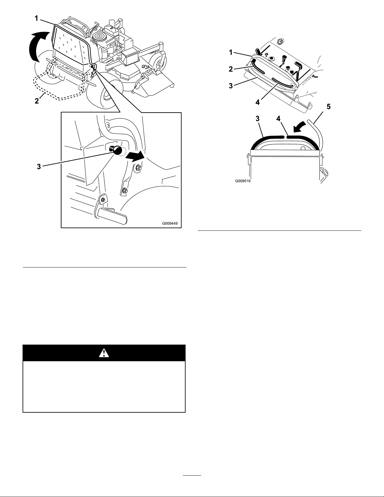
RaisingtheMowerforAccess
Thefrontofthemowercanberaisedandsupportedon
itsbackforaccessunderthemachineformaintenance.
1.Raisetheplatform.RefertoOperatingthePlatform
inOperation.
2.Removethebattery.
1.Cap
2.Pieceofplastic
Figure31
3.Hydraulictank
Figure30
1.Wingnut4.Positivebatterycable
2.Batterycover5.Battery
3.Negativebatterycable
3.Drainthefuelfromthefueltank.RefertoDraining
theFuelTankinMaintenance.
4.Removethecapofthehydraulictankandplace
apieceofplasticovertheopeningandinstallthe
hydrauliccap.Thiswillsealthehydraulictankand
preventitfromleakingout.
5.Withtwopeople,raisethefrontofthemowersoit
restsonthedrivetiresandtheplatformintheup
position.
6.Performanymaintenanceonthemachine.
7.Withtwopeople,lowerthefrontofthemowerto
theground.
8.Removetheplasticunderthehydraulictankcap.
9.Installthebatteryforthemachine.
27
Page 28

Figure32
1.Removebattery
2.Withtwopeople,liftthe
frontendofthemower
(ensuretheplatformisup)
RemovetheCushionforRear
Access
Thecushioncanberemovedforrearaccesstothe
machineformaintenanceoradjustment.
1.Lowertheplatform.
2.Removethehairpincotterpinsoneachsideofthe
cushion.
3.Slidethecushiontothesidetoremoveitfromthe
pinsandplasticbushingsonbothsides.
Figure33
1.Pin3.Hairpincotterpin
2.Cushionbracket
4.Plasticbushing
4.Lowerthecushiontotheplatform.
5.Performanymaintenanceoradjustmentonthe
machine.
6.Installtheplasticbushingsontothepins(Figure33).
7.Raisethecushionandslideitontothepinsonboth
sidesofthemachine.
8.Slidetheplasticbushingsintothecushionbracket
andsecurethemwithahairpincotterpin(Figure33).
28
Page 29

Lubrication
GreasewithNo.2generalpurposelithiumbaseor
molybdenumbasegrease.
Lubricatethetractionrollerswithadrylubricant
(PTFE).
HowtoGrease
1.DisengagethePTOandsettheparkingbrake.
2.Stoptheengine,removethekey,andwaitforall
movingpartstostopbeforeleavingtheoperating
position.
3.Cleanthegreasettingswitharag.Makesureto
scrapeanypaintoffthefrontofthetting(s).
4.Connectagreaseguntothetting.Pumpgrease
intothettingsuntilgreasebeginstooozeoutof
thebearings.
5.Wipeupanyexcessgrease.
Figure34
LubricatingtheMachine
ServiceInterval:Every200hours—Greasethemower
deckspindles(moreoftenindirtyor
dustyconditions).
Every200hours—Greasethelift
linkage(moreoftenindirtyordusty
conditions).
Every800hours/Yearly(whichever
comesrst)—Greasethefrontwheel
bearings(moreoftenindirtyordusty
conditions).
Every800hours/Yearly(whichever
comesrst)—Greasethefrontcaster
pivots(moreoftenindirtyordusty
conditions).
Every800hours/Yearly(whichever
comesrst)—Lubricatethetraction
rollers(moreoftenindirtyordusty
conditions).
Usethefollowinggraphicsforlocatingthegreasepoints.
Figure35
Lubricatethetractionrollerswithadrylubricant.
29
Figure36
Page 30

Figure37
EngineMaintenance
ServicingtheAirCleaner
ServiceInterval/Specication
Inspectthefoamandpaperelementsandreplacethem
iftheyaredamagedorexcessivelydirty.
Note:Servicetheaircleanermorefrequently(every
fewoperatinghours)iftheoperatingconditionsare
extremelydustyorsandy.
Important:Donotoilthefoamorpaperelement.
RemovingtheFoamandPaper
Elements
1.DisengagethePTOandsettheparkingbrake.
2.Stoptheengine,removethekey,andwaitforall
movingpartstostopbeforeleavingtheoperating
position.
3.Cleanaroundtheaircleanertopreventdirt
fromgettingintotheengineandcausingdamage
(Figure38).
4.Unscrewthecoverknobandremovetheaircleaner
cover(Figure38).
5.Removethewingnutsandremovetheaircleaner
assembly(Figure38).
6.Carefullypullthefoamelementoffthepaper
element(Figure38).
30
Page 31

Figure38
19hpEngineShown
1.Engine4.Foamelement
2.Cover
3.Wingnut
5.Paperelement
6.Coverknob
InstallingtheFoamandPaperElements
Important:Topreventenginedamage,always
operatetheenginewiththecompletefoamand
paperaircleanerassemblyinstalled.
1.Carefullyslidethefoamelementontothepaperair
cleanerelement(Figure38).
2.Placetheaircleanerassemblyontotheaircleaner
baseandsecureitwiththe2wingnuts(Figure38).
3.Placetheaircleanercoverintopositionandtighten
thecoverknob(Figure38).
ServicingtheEngineOil
ServiceInterval:Beforeeachuseordaily—Checkthe
engineoillevel.
Aftertherst8hours—Changethe
engineoil.
Every100hours—Changetheengine
oil.(moreoftenindirtyordusty
conditions)
Every200hours—Changetheengine
oillter.
Note:Changetheoilmorefrequentlywhenthe
operatingconditionsareextremelydustyorsandy.
OilType:Detergentoil(APIserviceSF ,SG,SH,orSJ)
CleaningtheFoamAirCleanerElement
ServiceInterval:Every25hours
1.Washthefoamelementinliquidsoapandwarm
water.Whentheelementisclean,rinseitthoroughly.
2.Drytheelementbysqueezingitinacleancloth.
Important:Replacethefoamelementifitis
tornorworn.
ServicingthePaperAirCleaner
Element
ServiceInterval:Every50hours—Checkthepaperair
cleanerelement.
Every200hours—Replacethepaper
aircleanerelement.
1.Donotcleanthepaperlter,replaceit(Figure38).
2.Inspecttheelementfortears,anoilylm,ordamage
totherubberseal.
3.Replacethepaperelementifitisdamaged.
CrankcaseCapacity:58ounces(1.7liter)withthelter
removed;51ounces(1.5liter)withoutthelterremoved
Viscosity:Refertothetablebelow
Figure39
CheckingtheEngineOilLevel
Note:Checktheoilwhentheengineiscold.
31
Page 32

Contactwithhotsurfacesmaycausepersonal
G008792
1
2
5
6
7
3
9
10
4
8
injury.
Keephands,feet,face,clothingandotherbody
partsawaythemuferandotherhotsurfaces.
Important:Donotoverllthecrankcasewithoil
becausedamagetotheenginemayresult.Donot
runenginewithoilbelowthelowmarkbecausethe
enginemaybedamaged.
1.DisengagethePTO,movethemotioncontrollevers
totheneutrallockedpositionandsettheparking
brake.
2.Stoptheengine,removethekey,andwaitforall
movingpartstostopbeforeleavingtheoperating
position(Figure40).
Figure40
ChangingtheEngineOil
Note:Disposeoftheusedoilatarecyclingcenter.
1.Starttheengineandletitrunveminutes.This
warmstheoilsoitdrainsbetter.
2.Parkthemachinesothatthedrainsideisslightly
lowerthantheoppositesidetoassuretheoildrains
completely.
32
Page 33

3.DisengagethePTO,movethemotioncontrollevers
G008796
2
3
4
5
6
1
totheneutrallockedpositionandsettheparking
brake.
4.Stoptheengine,removethekey,andwaitforall
movingpartstostopbeforeleavingtheoperating
position(Figure41).
Figure42
Figure41
5.Slowlypourapproximately80%ofthespeciedoil
intothellertubeandslowlyaddtheadditionaloil
tobringittotheFullmark(Figure42).
ChangingtheEngineOilFilter
Note:Changetheengineoilltermorefrequently
whenoperatingconditionsareextremelydustyorsandy.
1.Draintheoilfromtheengine;refertoChangingthe
EngineOil.
2.Changetheengineoillter(Figure43).
33
Page 34

G008748
3/4
1
2
3
4
5
6
Typefor19hpEngines:Champion
G008794
1
2
equivalent
®
RCJ8Yor
Typefor23hpEngines:NGK
AirGap:0.030inch(0.75mm)
®
BPR4ESorequivalent
RemovingtheSparkPlug
1.DisengagethePTO,movethemotioncontrollevers
totheneutrallockedpositionandsettheparking
brake.
2.Stoptheengine,removethekey,andwaitforall
movingpartstostopbeforeleavingtheoperating
position.
Figure43
Note:Ensuretheoilltergaskettouchestheengine
andthenanextra3/4turniscompleted.
3.Fillthecrankcasewiththepropertypeofnewoil;
refertoChangingtheOil.
ServicingtheSparkPlug
ServiceInterval:Every100hours
Makesuretheairgapbetweenthecenterandside
electrodesiscorrectbeforeinstallingthesparkplug.
Useasparkplugwrenchforremovingandinstalling
thesparkplug(s)andagappingtool/feelergaugeto
checkandadjusttheairgap.Installanewsparkplug(s)
ifnecessary.
Note:Therearedifferentsparkplugsforthe19hpand
23hpengines.Ensurethecorrectsparkplugisused.
Figure44
CheckingtheSparkPlug
Important:Nevercleanthesparkplug(s).Always
replacethesparkplug(s)whenithas:ablack
coating,wornelectrodes,anoilylm,orcracks.
Ifyouseelightbrownorgrayontheinsulator,the
engineisoperatingproperly .Ablackcoatingonthe
insulatorusuallymeanstheaircleanerisdirty.
Setthegapto0.030inches(0.76mm).
Figure45
34
Page 35

InstallingtheSparkPlug
Tightenthesparkplug(s)to16ft.-lb(22N-m).
Figure46
FuelSystem
Maintenance
DrainingtheFuelTank
Note:Thereisnootherrecommendedwaytodrain
fuelfromthetank,otherthanusingasyphonpump.A
syphonpumpcanbepurchasedatahardwarestore.
Incertainconditions,gasolineisextremely
ammableandhighlyexplosive.Areor
explosionfromgasolinecanburnyouand
othersandcandamageproperty.
•Draingasolinefromthefueltankwhenthe
engineiscold.Dothisoutdoorsinanopen
area.Wipeupanygasolinethatspills.
•Neversmokewhendraininggasoline,and
stayawayfromanopenameorwherea
sparkmayignitethegasolinefumes.
1.Parkthemachineonalevelsurface.Disengagethe
powertakeoff(PTO),settheparkingbrake,turnthe
ignitionkeytoOffandremovethekey.
2.Cleanaroundthefuelcaptopreventdebrisfrom
gettingintothefueltank(Figure48).
3.Removethefuelcap.
4.Insertasyphonpumpintothefueltank.
5.Usingthesyphonpump,drainthefuelintoaclean
gascan(Figure47).
6.Wipeupanyspilledfuel.
Figure47
1.Fuelcap
35
Page 36

ServicingtheFuelFilter
ElectricalSystem
ReplacingtheFuelFilter
ServiceInterval:Every400hours/Yearly(whichever
comesrst)
Neverinstalladirtylterifitisremovedfromthefuel
line.
Note:Notehowthefuellterisinstalledinorderto
installthenewltercorrectly.
Note:Wipeupanyspilledfuel.
1.DisengagethePTOandsettheparkingbrake.
2.Stoptheengine,removethekey,andwaitforall
movingpartstostopbeforeleavingtheoperating
position.
3.Closefuelshut-offvalve.
4.Squeezetheendsofthehoseclampstogetherand
slidethemawayfromthelter(Figure48).
Maintenance
ServicingtheBattery
Alwayskeepthebatterycleanandfullycharged.Use
apapertoweltocleanthebatterycase.Ifthebattery
terminalsarecorroded,cleanthemwithasolutionof
fourpartswaterandonepartbakingsoda.Applyalight
coatingofgreasetothebatteryterminalstoprevent
corrosion.
Voltage:12V
Warning
CALIFORNIA
Proposition65Warning
Batteryposts,terminals,andrelated
accessoriescontainleadandleadcompounds,
chemicalsknowntotheStateofCalifornia
tocausecancerandreproductiveharm.
Washhandsafterhandling.
Figure48
1.Hoseclamp3.Filter
2.Fuelline
5.Removethelterfromthefuellines.
6.Installanewlterandmovethehoseclampsclose
tothelter.
7.Openthefuelshut-offvalve.
8.Checkforfuelleaksandrepairifneeded.
9.Wipeupanyspilledfuel.
Batteryelectrolytecontainssulfuricacidwhich
isadeadlypoisonandcausessevereburns.
Donotdrinkelectrolyteandavoidcontactwith
skin,eyesorclothing.Wearsafetyglassesto
shieldyoureyesandrubberglovestoprotect
yourhands.
RemovingtheBattery
Batteryterminalsormetaltoolscouldshort
againstmetalmachinecomponentscausing
sparks.Sparkscancausethebatterygassesto
explode,resultinginpersonalinjury.
•Whenremovingorinstallingthebattery,do
notallowthebatteryterminalstotouchany
metalpartsofthemachine.
•Donotallowmetaltoolstoshortbetween
thebatteryterminalsandmetalpartsofthe
machine.
36
Page 37

Incorrectbatterycableroutingcoulddamage
themachineandcablescausingsparks.Sparks
cancausethebatterygassestoexplode,
resultinginpersonalinjury.
•AlwaysDisconnectthenegative(black)
batterycablebeforedisconnectingthe
positive(red)cable.
•AlwaysReconnectthepositive(red)battery
cablebeforereconnectingthenegative
(black)cable.
1.DisengagethePTOandsettheparkingbrake.
2.Stoptheengine,removethekey,andwaitforall
movingpartstostopbeforeleavingtheoperating
position.
3.Lifttheblackrubbercoveronthenegativecable.
Disconnectthenegativebatterycablefromthe
negative(-)batteryterminal(Figure49).
4.Slidetheredterminalbootoffthepositive(red)
batteryterminal.Thenremovethepositive(red)
batterycable(Figure49).
5.Removethebatteryholddownplate(Figure49)and
removethebattery.
InstallingtheBattery
1.Placethebatteryontothemachine(Figure49).
2.Securethebatterywiththeholddownplate,j-bolts,
andlocknuts.
3.First,installthepositive(red)batterycableto
positive(+)batteryterminalwithanut,washerand
bolt(Figure49).Slidetherubbercoveroverthepost.
4.Theninstallthenegativebatterycableandground
wiretothenegative(-)batteryterminalwithanut,
washerandbolt(Figure49).Slidetherubbercover
overthepost.
Figure49
1.Wingnut4.Positivebatterycable
2.Batterycover5.Battery
3.Negativebatterycable
CheckingtheBatteryElectrolyteLevel
ServiceInterval:Every400hours
Batteryelectrolytecontainssulfuricacidwhich
isadeadlypoisonandcausessevereburns.
•Donotdrinkelectrolyteandavoidcontact
withskin,eyesorclothing.Wearsafety
glassestoshieldyoureyesandrubbergloves
toprotectyourhands.
•Fillthebatterywherecleanwaterisalways
availableforushingtheskin.
1.Lookatthesideofthebattery.Theelectrolytemust
beuptotheupperline(Figure50).Donotallowthe
electrolytetofallbelowtheLowerline(Figure50).
37
Page 38

Important:Alwayskeepthebatteryfullycharged
(1.265specicgravity).Thisisespeciallyimportant
topreventbatterydamagewhenthetemperatureis
below32°F(0°C).
1.Removethebatteryfromthechassis;referto
RemovingtheBattery.
Figure50
1.Ventcaps3.Lowerline
2.Upperline
2.Iftheelectrolyteislow,addtherequiredamountof
distilledwater;refertoAddingWatertotheBattery
inMaintenance.
AddingWatertotheBattery
Thebesttimetoadddistilledwatertothebatteryisjust
beforeyouoperatethemachine.Thisletsthewatermix
thoroughlywiththeelectrolytesolution.
1.Removethebatteryfromthemachine;referto
RemovingtheBatteryinMaintenance.
Important:Neverllthebatterywithdistilled
waterwhilethebatteryisinstalledinthe
machine.Electrolytecouldbespilledonother
partsandcausecorrosion.
2.Cleanthetopofthebatterywithapapertowel.
2.Checktheelectrolytelevel;refertoCheckingthe
ElectrolyteLevel.
3.Makesurethellercapsareinstalledinbattery.
Chargebatteryfor1hourat25to30ampsor6
hoursat4to6amps.
4.Whenthebatteryisfullycharged,unplugthecharger
fromtheelectricaloutlet,thendisconnectthe
chargerleadsfromthebatteryposts(Figure51).
5.Installthebatteryontothemachineandconnectthe
batterycables,refertoInstallingtheBattery.
Note:Donotrunthemachinewiththebattery
disconnected,electricaldamagemayoccur.
3.Removetheventcapsfromthebattery(Figure50).
4.Slowlypourdistilledwaterintoeachbatterycell
untiltheelectrolytelevelisuptotheUpperline
(Figure50)onthebatterycase.
Important:Donotoverllthebatterybecause
electrolyte(sulfuricacid)cancausesevere
corrosionanddamagetothechassis.
5.Waitvetotenminutesafterllingthebatterycells.
Adddistilledwater,ifnecessary,untiltheelectrolyte
levelisuptotheUpperline(Figure50)onthe
batterycase.
6.Reinstallthebatteryventcaps.
ChargingtheBattery
Chargingthebatteryproducesgassesthatcan
explode.
Neversmokenearthebatteryandkeepsparks
andamesawayfrombattery.
Figure51
1.PositiveBatteryPost
2.NegativeBatteryPost
3.Red(+)ChargerLead
4.Black(-)ChargerLead
ServicingtheFuses
Theelectricalsystemisprotectedbyfuses.Itrequires
nomaintenance.Ifafuseblows,checkthecomponent
orcircuitforamalfunctionorshort.
1.Removethecushionfromtherearofthemachine.
2.Pulloutonthefusetoremoveorreplaceit
(Figure52).
3.Installthecoverunderthecusion.
Note:Ensurethecorrectsizefuseisinstallwiththe
correctwirecolorasshowninFigure52.
38
Page 39

DriveSystem
Maintenance
AdjustingtheTracking
Note:Determinetheleftandrightsidesofthemachine
fromthenormaloperatingposition.
1.Pushbothcontrolleversforwardthesamedistance.
2.Checkifthemachinepullstooneside.Ifitdoes,
stopthemachineandsettheparkingbrake.
3.Removethecushionfromtherearofthemachine.
4.Rotatethethumbadjustmentonthesideofthe
machinethatittracksto(asviewedfromtherearof
themachine)(Figure53).
5.Adjustinquarter-turnincrementsuntilthemachine
tracksstraight.
Figure52
1.Controls
2.Wire
3.Fuses
6.Checkforpropertracking.
Figure53
1.Leftthumbadjustment3.Platformdown
2.Rightthumbadjustment
7.Repeatadjustmentuntilthetrackingiscorrect.
8.Checkthatthemachinedoesnotcreepfromneutral
withtheparkbrakesdisengaged.
Important:DoNotrotatethelinkagetoofar,as
thismaycausethemachinetocreepinneutral.
39
Page 40

CheckingtheTirePressure
ServiceInterval:Every50hours/Monthly(whichever
comesrst)
Maintaintheairpressureinthereartiresat12-14psi
(83-97kPa).Uneventirepressurecancauseanuneven
cut.
Note:Thefronttiresaresemi-pneumatictiresanddo
notrequireairpressuremaintenance.
Figure55
1.SpringWashers3.DustCap
2.LockNut
Figure54
AdjustingtheCasterPivot
Bearing
ServiceInterval:Every500hours/Yearly(whichever
comesrst)
1.Disengagethebladecontrolswitch(PTO),movethe
motioncontrolleverstotheneutrallockedposition
andsettheparkingbrake.
2.Stoptheengine,removethekey,andwaitforall
movingpartstostopbeforeleavingtheoperating
position.
3.Removethedustcapfromcasterandtightenlock
nut(Figure55).
4.Tightenthelocknutuntilthespringwashersareat
andthenbackoffa1/4turntoproperlysetthe
pre-loadonthebearings(Figure55).
ServicingtheCasterWheel
andBearings
Thecasterwheelsrotateonarollerbearingsupportedby
aspannerbushing.Ifthebearingiskeptwelllubricated,
wearwillbeminimal.Failuretokeepthebearingwell
lubricatedwillcauserapidwear.Awobblycasterwheel
usuallyindicatesawornbearing.
1.Removethelocknutandwheelboltholdingthe
casterwheeltothecasterfork(Figure56).
Important:Makesurespringwashersare
installedcorrectlyasshowninFigure55.
5.Installthedustcap(Figure55).
1.Locknut
2.WheelBolt5.RollerBearing
3.Bushing
40
Figure56
4.SpannerBushing
Page 41

2.Removeonebushing,thenpullthespannerbushing
androllerbearingoutofthewheelhub(Figure56).
3.Removetheotherbushingfromthewheelhub
andcleananygreaseanddirtfromthewheelhub
(Figure56).
4.Inspecttherollerbearing,bushings,spannerbushing
andinsideofthewheelhubforwear.Replaceany
defectiveorwornparts(Figure56).
5.Toassemble,placeonebushingintothewheelhub.
Greasetherollerbearingandspannerbushingand
slidethemintothewheelhub.Placethesecond
bushingintothewheelhub(Figure56).
6.Installthecasterwheelintothecasterforkand
securewiththewheelboltandlocknut.Tightenthe
locknutuntilthespannerbushingbottomsagainst
theinsideofthecasterforks(Figure56).
CoolingSystem
Maintenance
CleaningtheAirIntakeScreen
ServiceInterval:Beforeeachuseordaily
Beforeeachuseremoveanybuild-upofgrass,dirt
orotherdebrisfromthecylinderandcylinderhead
coolingns,airintakescreenonywheelend,and
carburetor-governorleversandlinkage.Thiswillhelp
insureadequatecoolingandcorrectenginespeedand
willreducethepossibilityofoverheatingandmechanical
damagetotheengine.
CleaningtheCoolingSystem
7.Greasethettingonthecasterwheel.
AdjustingtheElectricClutch
ServiceInterval:Every100hours—Checktheelectric
clutch.
Theclutchisadjustabletoensureproperengagement
andproperbraking.
1.Inserta0.015–0.021inch(0.381–0.533mm)feeler
gaugethroughoneinspectionslotinthesideofthe
assembly.Makesureitisbetweenthearmatureand
therotorfrictionsurfaces.
2.Tightenthelocknutsuntilthereisslightbindingon
thefeelergaugebutitcanbemovedeasilywithinthe
airgap(Figure57).
3.Repeatthisfortheremainingslots.
4.Checkeachslotagainandmakeslightadjustments
untilthefeelergaugebetweentherotorandarmature
withveryslightcontactbetweenthem.
ServiceInterval:Every100hours—Checkandclean
enginecoolingnsandshrouds.
1.DisengagethePTOandsettheparkingbrake.
2.Stoptheengine,removethekey,andwaitforall
movingpartstostopbeforeleavingtheoperating
position.
3.Removetheairintakescreenandfanhousing
(Figure58).
4.Cleanthedebrisandgrassfromtheengineparts.
5.Installairintakescreen,recoilstarterandfanhousing
(Figure58).
Figure57
1.Adjustingnut3.Feelergauge
2.Slot
41
Page 42

1.Guard
2.Engineairintakescreen
3.Bolt
Figure58
BrakeMaintenance
ServicingtheBrake
Beforeeachuse,checkbrakesonbothalevelsurface
andslope.
Alwayssettheparkingbrakewhenyoustopthemachine
orleaveitunattended.Iftheparkingbrakedoesnot
holdsecurely,anadjustmentisrequired.
CheckingtheParkingBrake
ServiceInterval:Beforeeachuseordaily
1.Parkthemachineonalevelsurface,disengagethe
PTO.
2.Stoptheengine,removethekey,andwaitforall
movingpartstostopbeforeleavingtheoperating
position.
3.Applytheparkingbrake.Settingtheparkingbrake
shouldtakeareasonableamountofforce.Ifthe
4.Fanhousing
5.Screw
parkingbrakedoesnotholdsecurely ,anadjustment
isrequired.RefertoAdjustingtheParkingBrake.
AdjustingtheBrakes
Iftheparkingbrakedoesnotholdsecurely,an
adjustmentisrequired.
1.Checkthebrakebeforeyouadjustit;referto
CheckingtheBrakes.
2.Parkthemachineonalevelsurface,disengagethe
PTO,andsettheparkingbrake.
3.Stoptheengine,removethekey,andwaitforall
movingpartstostopbeforeleavingtheoperating
position.
4.Releasetheparkingbrake;refertoReleasingthe
ParkingBrakeOperation.
5.Toadjustthebrake,removethehairpincotter
andclevispinfromthelowerbrakeleverandyoke
(Figure59).
6.Loosenthejamnut(Figure59).
7.Rotatetheyoke.Totightenthebrake,rotatethe
yokeup.Toloosenthebrake,rotatetheyokedown
(Figure59).
Note:Thebrakerodshouldbethreadedintoboth
yokesthesamedistance.
8.Securetheyoketolowerbrakeleverwiththehairpin
cotterpinandclevispin(Figure59).
9.Tightenthejamnut(Figure59).
10.Checkthebrakeoperationagain;refertoChecking
theBrake.
42
Page 43

BeltMaintenance
ReplacingtheMowerDeck
Belt
ServiceInterval:Every100hours—Checkthemower
deckbelt.
Squealingwhenthebeltisrotating,bladesslippingwhen
cuttinggrass,frayedbeltedges,burnmarksandcracks
aresignsofaworndeckbelt.Replacethedeckbeltif
anyoftheseconditionsareevident.
Figure59
1.JamNut4.Hairpincotterpin
2.Yoke5.Lowerbrakelever
3.Clevispin
11.Afterthebrakeisadjusted,theleverswitchneeds
tobechecked.
12.Checkthegapbetweenthebrakeleverandthe
switchasshowninFigure60.Thegapneedstobe
an1/8inch(3mm)withthebrakeengaged.
13.Ifneeded,loosenthescrewsholdingtheswitchand
adjusttheswitch.
1.DisengagethePTOandsettheparkingbrake.
2.Stoptheengine,removethekey,andwaitforall
movingpartstostopbeforeleavingtheoperating
position.
3.Unlatchandremovethebeltcovers.
4.Loosenthefrontidlerpulleybylooseningthenut.
5.Removethewornmowerbelt(Figure61).
6.Installthenewmowerbeltaroundthedeckpulleys
andclutchpulley(Figure61).
7.Usingaratchetintheidlerarm,tightentheidler
pulleyuntilthespringisstretched5-3/4inches(14.6
cm)fromhooktohook(Figure61).
8.Tightenthefrontidlerpulleybytighteningthenut.
9.Installthebeltcoversontothecuttingunitand
securethelatches.
1.1/8inch(3mm)gap
neededbetweenswitch
andbrakelever
2.Brakelever
Figure60
3.Switch
43
Page 44

1.Hydraulicpumps
2.Idlerpulley
3.Clutchpulley
Figure62
4.Clutchretainer
5.Clutchwireconnector
6.Pumpdrivebelt
Figure61
1.5-3/4inches(14.6cm)
fromhooktohook
2.Spring5.Squareholeforratchet
3.Springloadedidler
4.Ratchet
6.Nut
ReplacingthePumpDriveBelt
ServiceInterval:Every100hours—Checkthepump
drivebelt.
1.DisengagethePTOandsettheparkingbrake.
2.Stoptheengine,removethekey,andwaitforall
movingpartstostopbeforeleavingtheoperating
position.
3.Removethemowerdeckbelt.
4.Tiltthemachineonit’sback.Referto
Pre-Maintenanceatthebeginningofthe
MaintenanceSection.
5.Disconnecttheclutchwireconnectorfromthewire
harness.
7.Unhooktheidlerspringfromtheframe(Figure62).
8.Installthenewbeltaroundclutchandthetwopump
pulleys.
9.Installtheidlerspringbetweenidlerarmandframe
bracket(Figure62).
10.Installtheclutchretainertotheenginedeck
(Figure62).
11.Connecttheclutchwireconnectortothewire
harness.
12.Lowerthemachinetotheoperatingposition.
RefertoPre-Maintenanceatthebeginningofthe
MaintenanceSection.
13.Installthemowerdeckbelt.
6.Disconnecttheclutchretainerfromtheenginedeck
(Figure62).
44
Page 45

ControlsSystem
Maintenance
AdjustingtheMotionControl
HandlePositions
AdjustingtheRightSideMotionControl
Lever
Ifthemotioncontrolleversdonotalignhorizontally ,
adjusttherightsidemotioncontrollever.
Note:Adjustthehorizontalalignmentbeforethefront
tobackalignment.
1.DisengagethePTO,movetherightsidemotion
controllevertotheneutralpositionandsetthe
parkingbrake.
1.Switchscrews
2.Cam
Figure64
3.Nutandbolt
2.Stoptheengine,removethekey,andwaitforall
movingpartstostopbeforeleavingtheoperating
position.
3.Pushtherightmotioncontrolleverdownoutof
lockedneutralposition(Figure63).
4.Checkifitalignshorizontallywiththeleftmotion
controllever(Figure63).
Figure63
1.Leftmotioncontrollever3.Checkthehorizontal
2.Rightmotioncontrollever
inneutrallockedposition
alignmenthere
4.Rightmotioncontrollever
9.Afterthecamisadjusted,theleverswitchneedsto
bechecked.
10.Checkthegapbetweenthecontrolleverandswitch
asshowninFigure65.Thegapneedstobean1/8
inch(3mm)withtherightmotioncontrolleverin
theneutral,unlockedposition.
11.Ifneeded,loosenthescrewsholdingtheswitchand
adjusttheswitch(Figure64andFigure65).
5.Toadjusttherightmotioncontrolleverhorizontally,
thecamneedstobeadjusted.
6.Removethecushionfromtherearofthemachine.
7.Loosenthenutandboltholdingthecam(Figure64).
8.Adjustthecamuntilitalignswiththeleftmotion
controlleverandtightenthenutandboltforthe
cam.
45
Page 46

Figure65
1.Switch
2.1/8inch(3mm)
3.Rightmotioncontrollever
intheneutralunlocked
position
12.Tightentheswitchscrews.
AdjustingtheNeutralPostionforthe
MotionControlLevers
Important:Ensurethetrackingofthemoweris
correctafteradjustingthemotioncontrollevers.
Adjustingthetrackingandaligningthemotion
controlleversfronttobackisthesameprocedure
(Figure66).
Figure66
1.Leftmotioncontrollever
2.Rightmotioncontrollever4.Alignthecontrollevers
3.Neutrallockedposition
fronttoback
2.Rotatethethumbadjustmentsoneitherside.Adjust
theminquarter-turnincrementsuntiltherightside
controllevermoveseasilyintotheneutrallock
positionandthecontrolleversalign.
3.Checkforpropertracking.RefertoAdjustingthe
TrackingintheMaintenanceSection.
Note:Adjustthehorizontalalignmentbeforethefront
tobackalignment.
Ifthemotioncontrolleversdonotalignfronttoback,
ortherightsidecontrolleverdoesnotmoveeasilyinto
theneutrallockposition,adjustmentisrequired.
1.Afterthehorizontalalignmentisnished,checkthe
fronttobackalignment(Figure66).
Figure67
1.Leftthumbadjustment3.Platformdown
2.Rightthumbadjustment
46
Page 47

HydraulicSystem
Maintenance
ServicingtheHydraulic
8.Rechecktheuidlevelwhiletheuidiswarm.If
required,adduidtothereservoiruntilitreaches
thehotlevelofthebafe.
Note:Theuidlevelshouldbetothetopofthehot
levelofthebafe,whentheuidiswarm(Figure68).
System
CheckingtheHydraulicFluid
ServiceInterval:Aftertherst8hours
Every50hours
HydraulicOilType:Toro
®
Mobil
syntheticoil..
Important:Useoilspeciedorequivalent.Other
uidscouldcausesystemdamage.
HydraulicSystemOilCapacity:67oz.(2.0l)
Note:Therearetwowaysofcheckingthehydraulicoil.
Oneiswhentheoiliswarmandoneiswhentheoilis
cold.Thebafeinsidethetankhastwolevelsdepending
iftheoiliswarmorcold.
1.Positionmachineonalevelsurface.
2.Disengagethepowertakeoff(PTO)andshutoff
3.Waitforallmovingpartstostopbeforeleavingthe
4.Cleanareaaroundcapandllerneckofhydraulic
115W-50syntheticmotoroilorequivalent
theengine.
operatingpositionandthensettheparkingbrake.
tank(Figure68).
®
15w-50hydraulicoilor
9.Installcaponllerneck.
Hydraulicuidescapingunderpressurecan
penetrateskinandcauseinjury.
•Ifhydraulicuidisinjectedintotheskin
itmustbesurgicallyremovedwithinafew
hoursbyadoctorfamiliarwiththistypeof
injury.Gangrenemayresultifthisisnot
done.
•Keepbodyandhandsawayfrompinhole
leaksornozzlesthatejecthighpressure
hydraulicuid.
•Usecardboardorpapertondhydraulic
leaks.
•Safelyrelieveallpressureinthehydraulic
systembeforeperforminganyworkonthe
hydraulicsystem.
•Makesureallhydraulicuidhosesand
linesareingoodconditionandallhydraulic
connectionsandttingsaretightbefore
applyingpressuretohydraulicsystem.
Figure68
1.Cap3.Colduidlevel-full
2.Bafe4.Hotuidlevel-full
5.Removecapfromllerneck.Lookinsidetocheck
theuidlevelinthereservoir.(Figure68).
6.Adduidtothereservoiruntilitreachesthecold
levelofthebafe.
7.Runthemachineatlowidlefor15minutestoallow
anyairtopurgeoutofthesystemandwarmuid.
RefertoStartingandStoppingtheEngine.
ReplacingtheHydraulicFilter
ServiceInterval:Aftertherst8hours
Every400hours
Hothydraulicuidcancausesevereburns.
Allowthehydraulicuidtocoolbefore
performinganymaintenancetothehydraulic
system.
1.DisengagethePTOandsettheparkingbrake.
2.Stoptheengineandwaitforallmovingpartstostop
beforeleavingtheoperatingposition.
Important:Donotsubstituteautomotiveoil
lterorseverehydraulicsystemdamagemay
result.
47
Page 48

3.Removehydraulicreservoircapandtemporarily
coveropeningwithaplasticbagandrubberbandto
preventallhydraulicuidfromdrainingout.
4.Locatethelterunderthefueltankandplacedrain
panunderlter(Figure69).
Figure69
1.Hydraulictank
2.Hydrauliclter
Figure70
1.Hydrauliclter
2.Gasket
3.Adapter
10.Cleanupanyspilleduid.
11.Checktheuidinthereservoir,adduidtothetank
untilitreachesthecoldbafeofthetank.
Important:Useoilspeciedorequivalent.
Otheruidscouldcausesystemdamage.
12.Startengineandletrunforabouttwominutesto
purgeairfromthesystem.Stoptheengineand
checkforleaks.Ifoneorbothwheelswillnotdrive,
refertoBleedingHydraulicSystem.
13.Rechecklevelandadduid,ifrequired.Donot
overll.
5.Removetheoldlterandwipethelteradapter
gasketsurfaceclean(Figure70).
6.Applyathincoathydraulicuidtotherubbergasket
onthereplacementlter.
7.Installreplacementhydrauliclterontothelter
adapter.Donottighten.
8.Removeplasticbagfromreservoiropeningand
allowltertollwithhydraulicuid.
9.Whenthehydrauliclterisfull,turntheoillter
clockwiseuntiltherubbergasketcontactsthelter
adapter,thentightenthelteranadditional1/2turn
(Figure70).
BleedingtheHydraulicSystem
Thetractionsystemisselfbleeding,however,itmaybe
necessarytobleedthesystemifuidischangedorafter
workisperformedonthesystem.
1.DisengagethePTOandsettheparkingbrake.
2.Stoptheengineandwaitforallmovingpartstostop
beforeleavingtheoperatingposition.
3.Raisetherearofthemachineupontojackstands
highenoughtoraisethedrivewheelsofftheground.
4.Starttheengineandmovethethrottlecontroltoidle
position.
Ifthedrivewheeldoesnotrotate,itispossibleto
assistthepurgingofthesystembycarefullyrotating
thetireintheforwarddirection.
5.Checkthehydraulicuidlevelasitdropsadduid
asrequiredtomaintaintheproperlevel.
6.Repeatthisprocedurefortheoppositewheel.
7.Thoroughlycleantheareaaroundeachofthecharge
pumphousings.
CheckingtheHydraulicLines
ServiceInterval:Every100hours
48
Page 49

Checkhydrauliclinesandhosesforleaks,loosettings,
kinkedlines,loosemountingsupports,wear,weather
andchemicaldeterioration.Makenecessaryrepairs
beforeoperating.
MowerDeck
Maintenance
Note:Keepareasaroundhydraulicsystemcleanfrom
grassanddebrisbuildup.
Hydraulicuidescapingunderpressurecan
penetrateskinandcauseinjury.
•Ifhydraulicuidisinjectedintotheskin
itmustbesurgicallyremovedwithinafew
hoursbyadoctorfamiliarwiththistypeof
injury.Gangrenemayresultifthisisnot
done.
•Keepbodyandhandsawayfrompinhole
leaksornozzlesthatejecthighpressure
hydraulicuid.
•Usecardboardorpapertondhydraulic
leaks.
•Safelyrelieveallpressureinthehydraulic
systembeforeperforminganyworkonthe
hydraulicsystem.
•Makesureallhydraulicuidhosesand
linesareingoodconditionandallhydraulic
connectionsandttingsaretightbefore
applyingpressuretohydraulicsystem.
ServicingtheCuttingBlades
Toensureasuperiorqualityofcut,keeptheblades
sharp.Forconvenientsharpeningandreplacement,you
maywanttokeepextrabladesonhand.
Awornordamagedbladecanbreak,anda
pieceofthebladecouldbethrownintothe
operator’sorbystander’sarea,resultingin
seriouspersonalinjuryordeath.
•Inspectthebladesperiodicallyforwearor
damage.
•Replaceawornordamagedblade.
BeforeInspectingorServicingthe
Blades
Parkthemachineonalevelsurface,disengagetheblades
andsettheparkingbrake.Turntheignitionkeytooff.
Removethekeyanddisconnectthesparkplugwires
fromthesparkplugs.
InspectingtheBlades
ServiceInterval:Beforeeachuseordaily
1.Inspectthecuttingedges(Figure71).Iftheedges
arenotsharporhavenicks,removeandsharpenthe
blades.RefertoSharpeningtheBlades.
2.Inspecttheblades,especiallythecurvedarea.Ifyou
noticeanycracks,wear,oraslotforminginthisarea
immediatelyinstallanewblades(Figure71).
Figure71
1.CuttingEdge3.Wear/slotForming
2.CurvedArea4.Crack
49
Page 50

CheckingforBentBlades
RemovingtheBlades
1.DisengagethePTO,movethemotioncontrollevers
totheneutrallockedpositionandsettheparking
brake.
2.Stoptheengine,removethekey,andwaitforall
movingpartstostopbeforeleavingtheoperating
position.
3.Rotatethebladesuntiltheendsfaceforwardand
backward.Measurefromalevelsurfacetothe
cuttingedge,positionA,oftheblades(Figure72
).Notethisdimension.
Bladesmustbereplacedifasolidobjectishit,ifthe
bladeisoutofbalanceorisbent.Toensureoptimum
performanceandcontinuedsafetyconformanceof
themachine,usegenuineTororeplacementblades.
Replacementbladesmadebyothermanufacturersmay
resultinnon-conformancewithsafetystandards.
1.Holdthebladeendusingaragorthickly-padded
glove.
2.Removethebladebolt,curvedwasher,andblade
fromthespindleshaft(Figure73).
Figure72
40inch,48inch,and52inchMowerDeckshown
1.Measureherefromblade
tohardsurface
2.PositionA
4.Rotatetheoppositeendsofthebladesforward.
5.Measurefromalevelsurfacetothecuttingedgeof
thebladesatthesamepositionasinstep3above.
Thedifferencebetweenthedimensionsobtainedin
steps3and4mustnotexceed1/8inch(3mm).If
thisdimensionexceeds1/8inch(3mm),theblade
isbentandmustbereplaced;refertoRemovingthe
BladesandInstallingtheBlades.
Abladethatisbentordamagedcouldbreak
apartandcouldseriouslyinjureorkillyouor
bystanders.
•Alwaysreplacebentordamagedbladewith
anewblade.
•Neverleorcreatesharpnotchesinthe
edgesorsurfacesofblade.
Figure73
1.SailAreaofBlade3.Curvedwasher
2.Blade4.BladeBolt
SharpeningtheBlades
1.Usealetosharpenthecuttingedgeatbothends
oftheblade(Figure74).Maintaintheoriginalangle.
Thebladeretainsitsbalanceifthesameamountof
materialisremovedfrombothcuttingedges.
Figure74
1.Sharpenatoriginalangle
2.Checkthebalanceofthebladebyputtingitona
bladebalancer(Figure75).Ifthebladestaysina
horizontalposition,thebladeisbalancedandcanbe
used.Ifthebladeisnotbalanced,lesomemetaloff
50
Page 51

theendofthesailareaonly(Figure73).Repeatthis
procedureuntilthebladeisbalanced.
2.Stoptheengine,removethekey,andwaitforall
movingpartstostopbeforeleavingtheoperating
position.Disconnectthesparkplugwire(s)from
thesparkplug(s).
3.Adjustthetirepressureinthereartiresto12-14psi
(83-97kPa).
Figure75
1.Blade2.Balancer
InstallingtheBlades
1.Installthebladeontothespindleshaft(Figure76).
Important:Thecurvedpartoftheblademust
bepointingupwardtowardtheinsideofthe
mowertoensurepropercutting.
2.Installthespringdiskandbladebolt.Thespring
diskconemustbeinstalledtowardthebolthead
(Figure76).Torquethebladeboltto85-110ft-lb
(115-150N-m).
4.Checkthatthebladesandspindleshaftsarenot
bent.RefertoCheckingforBentBlades.
5.Settheheight-of-cuttothe3inch(7.6cm)position.
RefertoAdjustingtheHeight-Of-CutinOperation.
6.Performthestepsinthefollowingproceduresin
order.
CheckingtheMowerDeckSide-to-Side
Height
1.Adjustthereartirepressure.
2.Ensurethebladesarenotbent.RefertoChecking
forBentBlades.
3.Positionthebladesside-to-side.MeasureatBand
Clocationsfromalevelsurfacetothecuttingedge
ofbladetips(Figure77).
Figure76
1.SailAreaofBlade
2.Blade
3.SpringDisk
4.BladeBolt
5.ConeTowardsBoltHead
CorrectingtheMowerQuality
ofCut
Ifonedeckbladecutslowerthantheother,correctas
follows.
Note:Tireairpressureiscriticalintheseprocedures.
Makesurethereartireshavecorrectpressure.
1.DisengagethePTOandsettheparkingbrake.
Figure77
1.Measurefromalevel
surface
2.MeasurebladeatpointsB
andC
4.ThedifferencebetweenmeasurementsBandC
shouldbenomorethan1/4inch(6mm).IIfitis
notcorrect,proceedtoChangingtheMowerDeck
Side-to-SideHeight.
ChangingtheMowerDeckSide-to-Side
Height
Changingtheside-to-sideheightisdonebyadjusting
thereartirepressureandU-platesonthesideofthe
enginedeck.
51
Page 52

1.Changethereartirepressure.Dothistothe
correspondingsidethatneedsadjustment.
2.LocatetheU-platesonthesideoftheenginedeck
(Figure78).
3.LoosentheU-plateononesideandadjustitupor
downtomakethedifferencebetweenmeasurements
BandCnomorethana1/4inch(6mm)(Figure78).
4.ProceedtoCheckingtheMowerDeckFront-to-Rear
Pitch.
1.MeasurebladeatpointsA
andB
ChangingtheMowerDeck
Front-to-RearPitch
Figure79
2.Measurefromalevel
surface
Figure78
1.U-plate2.Nutsandbolts
CheckingtheMowerDeckFront-to-Rear
Pitch
1.Adjustthetirepressureinthereartiresto
specications.
2.Positiononebladefront-to-rear.MeasureatAand
Blocationsfromalevelsurfacetothecuttingedge
ofthebladetips(Figure79).
Changingthefront-to-rearpitchisdonebyadjustingthe
frontheight-of-cutposts.
1.Place3piecesof2x4woodunderthemowerdeck
asshowninFigure80.Standthe2x4’ sonthe4inch
part.
Figure80
1.2x4pieceofwoodundermowerdeck
3.Themowerbladeshouldbea1/4inch(6mm)lower
infrontatAthanintherearatB.Rotatebladesand
repeatforotherblades.Ifitisnotcorrect,proceed
toChangingtheDeckFront-to-RearPitch.
2.Loosenboththefrontandrearnutsonthe
adjustmentrods(Figure81).
3.Theweightofthemowerdeckmustberestingonall
threeofthe2x4’s(Figure81).Thebacklipofthe
mowerdeckisbuilta1/4inch(6mm)lowerthanthe
frontlipofthemowerdeck.
4.Tightenboththefrontandrearnuts.
52
Page 53

5.Checkthefront-to-rearpitchofthecuttingunit.
6.Ifthedimensionsarenotcorrect,adjustthefront
andrearnutsoneithersidetogetthecorrect
front-to-rearpitch(Figure81).
Figure82
1.Measurefromalevel
surface
2.MeasurebladeatpointA
4.Themeasurementshouldbe3inch(7.6cm).
5.Ifitdoesnotmeasurecorrectly,locatethe
height-of-cutrodontherightsideofthemachine
(Figure83).
Figure81
1.Adjustmentrods3.Frontnuts
2.Rearnuts
MatchingHeightofCut
1.Checkthereartirepressure.
2.Settheheight-of-cuttothe3inch(7.6cm)position.
RefertoAdjustingtheHeight-Of-CutinOperation.
3.Withthemachineonlevelsurface,positiononeblade
front-to-rear.MeasureatAandfromlevelsurfaceto
thecuttingedgeofthebladetips(Figure82).
6.Loosenthejamnutandadjusttheadjustment
nutuntilthebladetipsmatch3inches(7.6cm)
(Figure83).
7.Whentheadjustmentiscorrect,tightenthejamnut
(Figure83).
1.Height-of-cutrod
2.Jamnut
53
Figure83
3.Adjustmentnut
Page 54

ReplacingtheGrassDeector
Anuncovereddischargeopeningcouldallow
thelawnmowertothrowobjectsinthe
operator’sorbystander’sdirectionandresult
inseriousinjury.Also,contactwiththeblade
couldoccur.
Neveroperatethelawnmowerunlessyouinstall
acoverplate,amulchplate,grassdeectoror
bagger.
1.Removethelocknut,bolt,springandspacerholding
thedeectortothepivotbrackets(Figure84).
Removedamagedorworngrassdeector.
positionandensurethatitrotatesintothefull
downposition.
Figure84
1.Bolt
2.Spacer6.GrassDeector
3.Locknut
4.Spring8.Jhookendofspring
5.Springinstalled
7.Lendofspring,place
behinddeckedgebefore
installingbolt
2.Placespacerandspringontograssdeector.Place
theLendofspringbehinddeckedge.
Note:MakesuretheLendofspringisinstalled
behinddeckedgebeforeinstallingtheboltasshown
inFigure84.
3.Installboltandnut.PlacetheJhookendofspring
aroundgrassdeector(Figure84).
Important:Thegrassdeectormustbeable
torotate.Liftthedeectoruptothefullopen
54
Page 55

Cleaning
Storage
CleaningUndertheMower
ServiceInterval:Beforeeachuseordaily
Removethegrassbuildupunderthemowerdaily.
1.DisengagethePTO,movethemotioncontrollevers
totheneutrallockedpositionandsettheparking
brake.
2.Stoptheengine,removethekey,andwaitforall
movingpartstostopbeforeleavingtheoperating
position.
3.Raisethefrontofthemachineandusejackstandsto
supportthemower.
WasteDisposal
Engineoil,batteries,hydraulicoil,andenginecoolant
arepollutantstotheenvironment.Disposeofthese
accordingtoyourstateandlocalregulations.
CleaningandStorage
1.Disengagethepowertakeoff(PTO),settheparking
brake,andturntheignitionkeytooff.Removethe
key.
2.Removegrassclippings,dirt,andgrimefromthe
externalpartsoftheentiremachine,especiallythe
engine.Cleandirtandchafffromtheoutsideofthe
engine’scylinderheadnsandblowerhousing.
Important:Youcanwashthemachinewith
milddetergentandwater.Donotpressurewash
themachine.Avoidexcessiveuseofwater,
especiallynearthedrivesystemandengine.
Pressurewashingcanforcedirtandwaterinto
criticalparts,suchasspindlebearingsand
electricalswitches.
3.Checkthebrake;refertoServicingtheBrakein
BrakeMaintenance,page42.
4.Servicetheaircleaner;refertoServicingtheAir
CleanerinEngineMaintenance,page30.
5.Greasethemachine;refertoGreasingand
LubricationinLubrication,page29.
6.Changetheengineoil;refertoServicingtheEngine
inEngineMaintenance,page30.
7.Checkthetirepressure;refertoCheckingtheTire
PressureinDriveSystemMaintenance,page39.
8.Forlong-termstorage:
A.Addstabilizer/conditioneradditivetofuelinthe
tank.
B.Runenginetodistributeconditionedfuelthrough
thefuelsystem(5minutes).
C.Stopengine,allowtocoolanddrainthefuel
tank;refertoServicingtheFuelTankinFuel
SystemMaintenance,page35,oroperateengine
untilitstops.
D.Restartengineandrununtilitstops.Repeat,on
Chokeuntilenginewillnotrestart.
E.Disposeoffuelproperly.Recycleasperlocal
codes.
Note:Donotstorestabilizer/conditioned
gasolineover90days.
9.Removethesparkplug(s)andcheckitscondition;
refertoServicingtheSparkPluginEngine
Maintenance,page30.Withthesparkplug(s)
removedfromtheengine,pourtwotablespoonsof
engineoilintothesparkplughole.Nowusethe
startertocranktheengineanddistributetheoil
55
Page 56

insidethecylinder.Installthesparkplug(s).Donot
installthewireonthesparkplug(s).
10.Checkandtightenallbolts,nuts,andscrews.Repair
orreplaceanypartthatisdamagedordefective.
11.Paintallscratchedorbaremetalsurfaces.Paintis
availablefromyourAuthorizedServiceDealer.
12.Storethemachineinaclean,drygarageorstorage
area.Removethekeyfromtheignitionswitchand
keepitinamemorableplace.Coverthemachineto
protectitandkeepitclean.
56
Page 57

Troubleshooting
Problem
Enginewillnotstart,startshard,orfails
tokeeprunning.
Enginelosespower.
PossibleCauseCorrectiveAction
1.Fueltankisempty.
2.Chokeisnoton.
3.Sparkplugwireislooseor
disconnected.
4.Sparkplugispitted,fouled,orthegap
isincorrect.
5.Aircleanerisdirty.
6.Dirtinthefuellter .6.Replacethefuellter.
7.Dirt,water,orstalefuelisinthefuel
system.
8.Thegapbetweenthesafetyinterlock
switchesisnotcorrect.
1.Engineloadisexcessive.1.Reducethegroundspeed.
2.Aircleanerisdirty.
3.Oillevelinthecrankcaseislow.
4.Coolingnsandairpassagesunder
theengineblowerhousingareplugged.
5.Sparkplugispitted,fouled,orthegap
isincorrect.
6.Ventholeinthefuelcapisplugged.6.Cleanorreplacethefuelcap.
7.Dirtinthefuellter .7.Replacethefuellter.
8.Dirt,water,orstalefuelisinthefuel
system.
1.Fillfueltankwithgasoline.
2.Movethechokelevertochokeposition.
3.Installwireonsparkplug.
4.Installanew,correctlygappedspark
plug.
5.Servicetheaircleanerelement.
7.ContactanAuthorizedServiceDealer .
8.ContactanAuthorizedServiceDealer .
2.Servicetheaircleaner.
3.Addoiltothecrankcase.
4.Removetheobstructionfromthe
coolingnsandairpassages.
5.Installanew,correctlygappedspark
plug.
8.ContactanAuthorizedServiceDealer .
Engineoverheats.
Machinedoesnotdrive.
Abnormalvibration.
Unevencuttingheight.
1.Engineloadisexcessive.1.Reducethegroundspeed.
2.Oillevelinthecrankcaseislow.
3.Coolingnsandairpassagesunder
theengineblowerhousingareplugged.
1.Hydraulicoilreservoirlow.1.Addhydraulicoiltothereservoir.
2.Airinthehydraulicsystem.2.Bleedtheairoutthehydraulicsystem.
3.Pumpdrivebeltslipping.3.Replacethepumpdrivebelt.
4.Pumpdrivebeltidlerspringmissing.4.Replacethepumpdrivebeltidler
5.Pumpby-passvalvesareopen.5.Tightentheby-passvalves.
1.Cuttingblade(s)is/arebentor
unbalanced.
2.Blademountingboltisloose.2.Tightentheblademountingbolt.
3.Enginemountingboltsareloose.3.Tightentheenginemountingbolts.
4.Looseenginepulley,idlerpulley ,or
bladepulley.
5.Enginepulleyisdamaged.
6.Bladespindleisbent.
1.Blade(s)notsharp.1.Sharpentheblade(s).
2.Cuttingblade(s)is/arebent.2.Installnewcuttingblade(s).
3.Mowerdeckisnotlevel.3.Levelthemowerdeckside-to-side
4.Mowerdeckpitchiswrong.
5.Undersideofmowerdeckisdirty.5.Cleantheundersideofthemower
6.Tirepressureisnotcorrect.6.Adjustthetirepressure.
7.Bladespindlebent.
2.Addoiltothecrankcase.
3.Removetheobstructionfromthe
coolingnsandairpassages.
spring.
1.Installnewcuttingblade(s).
4.Tightentheappropriatepulley .
5.ContactanAuthorizedServiceDealer .
6.ContactanAuthorizedServiceDealer .
position.
4.Adjustthefront-to-rearpitch.
deck.
7.ContactanAuthorizedServiceDealer .
57
Page 58

Problem
PossibleCauseCorrectiveAction
Bladesdonotrotate.
1.Pumpdrivebeltisworn,looseor
broken.
2.Pumpdrivebeltisoffpulley.
3.Mowerdeckbeltisworn,looseor
broken.
4.Mowerdeckbeltisoffpulley.
5.Brokenormissingidlerspring.5.Replacethespring.
6.Electricclutchoutofadjustment.
7.Clutchconnectororwiredamaged.7.ContactanAuthorizedServiceDealer .
8.Damagedelectricclutch.
9.Safetyinterlocksystempreventsblade
rotation.
10.PTOswitchisfaulty.10.ContactanAuthorizedServiceDealer.
1.Checkthebelttension.
2.Installdrivebeltandcheckadjusting
shaftsandbeltguidesforcorrect
position.
3.Installnewdeckbelt.
4.Installdeckpulleyandchecktheidler
pulley,idlerarmandspringforcorrect
positionandfunction.
6.Adjusttheclutchairgap.
8.ContactanAuthorizedServiceDealer .
9.ContactanAuthorizedServiceDealer .
58
Page 59

Schematics
HydraulicSchematic(Rev.A)
59
Page 60

ElectricalSchematic(Rev.A)
60
Page 61

Notes:
61
Page 62

Notes:
62
Page 63

Notes:
63
Page 64

The Toro Total Coverage Guarantee
A Limited Warranty (see warranty periods below)
Landscape
Contractor
Equipment (LCE)
The Toro Company and its affiliate, Toro Warranty Company, pursuant to an
Conditions and Products Covered
agreement between them, jointly promise to repair the listed Toro Products
if defective in materials or workmanship.
The following warranty time periods apply from the date of purchase by the
original owner:
Product Warranty Period
Mid-Size Walk-Behind Mowers 2 years**
GrandStand
•
•
Z Master
•
•
Z Master® G3 Mowers
•
•
Batteries (for above units)
TM
Mowers
Engine
Frame
®
Z300, Z400, Z500 Mowers
Engine
Frames
Engine
Frame
5 years or 1,200 hours*
2 years**
Lifetime (original owner only)***
4 years or 1,200 hours*
2 years**
Lifetime (original owner only)***
5 years or 1,200 hours*
2 years**
Lifetime (original owner only)***
1 year
Attachments (for above units) 1 year
*Whichever occurs fi rst.
**Some engines used on Toro LCE Products are warranted by the engine manufacturer.
***Lifetime Frame Warranty - If the main frame, consisting of the parts welded together to form
the tractor structure that other components such as the engine are secured to, cracks or breaks in
normal use, it will be repaired or replaced under warranty at no cost for parts and labor. Frame failure
due to misuse or abuse and failure or repair required due to rust or corrosion are not covered.
This warranty includes the cost of parts and labor, but you must pay
transportation costs.
Instructions for Obtaining Warranty Service
If you think that your Toro Product contains a defect in materials or
workmanship, follow this procedure:
1. Contact any Authorized Toro Service Dealer to arrange service at their
dealership. To locate a dealer convenient to you, refer to the Yellow
Pages of your telephone directory (look under “Lawn Mowers”) or access
our web site at www.Toro.com. You may also call the numbers listed in
item #3 to use the 24-hour Toro Dealer locator system.
2. Bring the product and your proof of purchase (sales receipt) to the
Service Dealer. The dealer will diagnose the problem and determine if it
is covered under warranty.
3. If for any reason you are dissatisfi ed with the Service Dealer’s analysis
or with the assistance provided, contact us at:
LCB Customer Service Department
Toro Warranty Company
8111 Lyndale Avenue South
Bloomington, MN 55420-1196
888-865-5676 (U.S. Customers)
888-865-5691 (Canada customers)
You must maintain your Toro Product by following the maintenance
Owner Responsibilities
procedures described in the Operator’s Manual. Such routine maintenance,
whether performed by a dealer or by you, is at your expense.
Items and Conditions Not Covered
There is no other express warranty except for special emission system and
engine warranty coverage on some products.
This express warranty does not cover:
Cost of regular maintenance service or parts, such as fi lters, fuel,
•
lubricants, tune-up parts, blade sharpening, brake and clutch
adjustments.
Any product or part which has been altered or misused or required
•
replacement or repair due to normal wear, accidents, or lack of proper
maintenance.
Repairs necessary due to improper fuel, contaminants in the fuel system,
•
or failure to properly prepare the fuel system prior to any period of nonuse over three months.
Pickup and delivery charges.
•
General Conditions
All repairs covered by this warranty must be performed by an Authorized
Toro Service Dealer using Toro approved replacement parts.
Neither The Toro Company nor Toro Warranty Company is liable for
indirect, incidental or consequential damages in connection with
the use of the Toro Products covered by this warranty, including any
cost or expense of providing substitute equipment or service during
reasonable periods of malfunction or non-use pending completion of
repairs under this warranty.
All implied warranties of merchantability (that the product is fit for
ordinary use) and fitness for use (that the product is fit for a particular
purpose) are limited to the duration of the express warranty.
Some states do not allow exclusions of incidental or consequential
damages, or limitations on how long an implied warranty lasts, so the
above exclusions and limitations may not apply to you.
This warranty gives you specifi c legal rights, and you may also have other
rights which vary from state to state.
Customers who have purchased Toro products outside the United States or Canada should contact their Toro Distributor (Dealer) to obtain guarantee
Countries Other than the United States or Canada
policies for your country, province, or state. If for any reason you are dissatisfi ed with your Distributor’s service or have diffi culty obtaining guarantee
information, contact the Toro importer. If all other remedies fail, you may contact us at Toro Warranty Company.
Part Number 374-0037 Rev. H
 Loading...