

Page 1

FormNo.3365-450RevA
GrandStand
®
Mower
Witha48in,52inor60inTURBOFORCE
CuttingUnit
ModelNo.74538—SerialNo.310000001andUp
ModelNo.74539—SerialNo.310000001andUp
ModelNo.74548—SerialNo.310000001andUp
ModelNo.74549—SerialNo.310000001andUp
ModelNo.74550—SerialNo.310000001andUp
ModelNo.74551—SerialNo.310000001andUp
ModelNo.79548—SerialNo.310000001andUp
ModelNo.79549—SerialNo.310000001andUp
®
ModelNo.79551—SerialNo.310000001andUp
ToregisteryourproductordownloadanOperator'sManualorPartsCatalogatnocharge,gotowww.T oro.com.OriginalInstructions(EN)
Page 2
WARNING
CALIFORNIA
Proposition65Warning
Theengineexhaustfromthisproduct
containschemicalsknowntotheStateof
Californiatocausecancer,birthdefects,
orotherreproductiveharm.
ThissparkignitionsystemcomplieswithCanadian
ICES-002.
Important:Thisengineisnotequippedwitha
sparkarrestermufer.ItisaviolationofCalifornia
PublicResourceCodeSection4442touseoroperate
theengineonanyforest-covered,brush-covered,or
grass-coveredland.Otherstatesorfederalareas
mayhavesimilarlaws.
Theenclosed
Engine Owner’ s Man ual
issupplied
forinformationregardingtheUSEnvironmental
ProtectionAgency(EPA)andtheCalifornia
EmissionControlRegulationofemissionsystems,
maintenance,andwarranty.Replacementsmaybe
orderedthroughtheenginemanufacturer.
Introduction
Thisrotary-blade,ridinglawnmowerisintendedto
beusedbyresidentialhomeownersorprofessional,
hiredoperators.Itisdesignedprimarilyforcutting
grassonwell-maintainedlawnsonresidential
orcommercialproperties.Itisnotdesignedfor
cuttingbrushorforagriculturaluses.
Readthisinformationcarefullytolearnhowtooperate
andmaintainyourproductproperlyandtoavoidinjury
andproductdamage.Youareresponsibleforoperating
theproductproperlyandsafely.
YoumaycontactTorodirectlyatwww .T oro.comfor
productandaccessoryinformation,helpndinga
dealer,ortoregisteryourproduct.
Wheneveryouneedservice,genuineToroparts,or
additionalinformation,contactanAuthorizedService
DealerorToroCustomerServiceandhavethemodel
andserialnumbersofyourproductready .
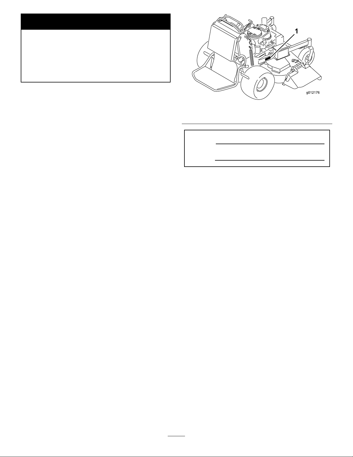
identiesthelocationofthemodelandserialnumbers
ontheproduct.Writethenumbersinthespace
provided.
Figure1
Figure1
1.Locationofthemodelandserialnumbers
ModelNo.
SerialNo.
Thismanualidentiespotentialhazardsandhassafety
messagesidentiedbythefollowingwords:
•Dangersignalsanextremehazardthatwillcause
seriousinjuryordeathifyoudonotfollowthe
recommendedprecautions.
•Warningsignalsahazardthatmaycauseserious
injuryordeathifyoudonotfollowtherecommended
precautions.
•Cautionsignalsahazardthatmaycauseminor
ormoderateinjuryifyoudonotfollowthe
recommendedprecautions.
Thismanualusestwootherwordstohighlight
information.Importantcallsattentiontospecial
mechanicalinformationandNoteemphasizesgeneral
informationworthyofspecialattention.
Contents
Introduction.................................................................2
Safety...........................................................................4
SafeOperatingPractices.......................................4
ToroMowerSafety...............................................5
SlopeIndicator.....................................................7
SafetyandInstructionalDecals.............................8
ProductOverview......................................................12
Controls.............................................................12
Specications.....................................................13
Operation...................................................................14
AddingFuel.......................................................14
CheckingtheEngineOilLevel............................15
BreakingInaNewMachine................................15
©2010—TheT oro®Company
8111LyndaleAvenueSouth
Bloomington,MN55420
Contactusatwww.T oro.com.
2
PrintedintheUSA.
AllRightsReserved
Page 3

ThinkSafetyFirst...............................................15
OperatingtheParkingBrake...............................15
OperatingtheMowerBladeControlSwitch
(PTO)............................................................16
OperatingtheThrottle.......................................16
OperatingtheChoke..........................................16
OperatingtheIgnitionSwitch.............................17
UsingtheSpeedControlLever...........................17
UsingtheFuelShut-OffValve............................17
StartingandStoppingtheEngine........................18
TheSafetyInterlockSystem................................19
OperatingthePlatform......................................20
DrivingForwardorBackward.............................21
StoppingtheMachine.........................................22
PushingtheMachinebyHand.............................22
TransportingMachines.......................................23
LoadingMachines..............................................23
SideDischargingorMulchingtheGrass..............24
AdjustingtheHeight-of-Cut...............................24
AdjustingtheAnti-ScalpRollers(60inch
MowerDecksOnly).......................................24
AdjustingtheFlowBafe...................................25
PositioningtheFlowBafe.................................25
UsingtheMid-SizeWeight..................................26
Maintenance...............................................................27
RecommendedMaintenanceSchedule(s)................27
PremaintenanceProcedures....................................28
RaisingtheMowerforAccess.............................28
ReleasetheCushionforRearAccess...................29
Lubrication.............................................................30
HowtoGrease...................................................30
LubricatingtheMachine.....................................30
GreasingtheFrontCasterPivots.........................31
LubricateCasterWheelHubs.............................31
EngineMaintenance...............................................32
ServicingtheAirCleaner....................................32
ServicingtheEngineOil.....................................34
ServicingtheSparkPlug.....................................36
FuelSystemMaintenance.......................................38
DrainingtheFuelTank.......................................38
ServicingtheFuelFilter......................................38
ElectricalSystemMaintenance................................39
ServicingtheBattery...........................................39
ServicingtheFuses.............................................40
DriveSystemMaintenance.....................................41
AdjustingtheTracking.......................................41
CheckingtheTirePressure.................................42
AdjustingtheCasterPivotBearing......................42
ServicingtheCasterWheelandBearings.............42
AdjustingtheElectricClutch..............................43
CoolingSystemMaintenance..................................44
CleaningtheAirIntakeScreen............................44
CleaningtheCoolingSystem...............................44
BrakeMaintenance.................................................45
ServicingtheBrake.............................................45
BeltMaintenance....................................................47
ReplacingtheMowerDeckBelt..........................47
ReplacingthePumpDriveBelt...........................47
ControlsSystemMaintenance.................................48
AdjustingtheMotionControlHandle
Positions........................................................48
HydraulicSystemMaintenance...............................50
ServicingtheHydraulicSystem...........................50
MowerDeckMaintenance......................................53
ServicingtheCuttingBlades...............................53
CorrectingtheMowerQualityofCut..................55
ReplacingtheGrassDeector.............................57
Cleaning.................................................................58
CleaningUndertheMower.................................58
WasteDisposal...................................................58
Storage.......................................................................59
CleaningandStorage..........................................59
Troubleshooting.........................................................60
Schematics.................................................................62
3
Page 4

Safety
Note:Theadditionofattachmentsmadeby
othermanufacturersthatdonotmeetAmerican
NationalStandardsInstitutecerticationwillcause
noncomplianceofthismachine.
Improperuseormaintenancebytheoperatoror
ownercanresultininjury.Toreducethepotential
forinjury,complywiththesesafetyinstructions
andalwayspayattentiontothesafetyalertsymbol
,whichmeansCAUTION,WARNING,or
DANGER-“personalsafetyinstruction."Failureto
complywiththeinstructionmayresultinpersonalinjury
ordeath.
–Useonlyanapprovedcontainer
–Neverremovegascaporaddfuelwithengine
running.Allowenginetocoolbeforerefueling.
Donotsmoke.
–Neverrefuelordrainthemachineindoors.
•Checkthatoperator’spresencecontrols,safety
switchesandshieldsareattachedandfunctioning
properly.Donotoperateunlesstheyarefunctioning
properly.
Operation
•Lightningcancausesevereinjuryordeath.If
lightningisseenorthunderisheardinthearea,do
notoperatethemachine;seekshelter.
•Neverrunanengineinanenclosedarea.
SafeOperatingPractices
ThefollowinginstructionsarefromANSIstandard
B71.4-2004.
Training
•ReadtheOperator’sManualandothertraining
material.Iftheoperator(s)ormechanic(s)cannot
readEnglishitistheowner’sresponsibilitytoexplain
thismaterialtothem.
•Becomefamiliarwiththesafeoperationofthe
equipment,operatorcontrols,andsafetysigns.
•Alloperatorsandmechanicsshouldbetrained.The
ownerisresponsiblefortrainingtheusers.
•Neverletchildrenoruntrainedpeopleoperateor
servicetheequipment.Localregulationsmayrestrict
theageoftheoperator.
•Theowner/usercanpreventandisresponsiblefor
accidentsorinjuriesoccurringtohimselforherself,
otherpeopleorproperty.
Preparation
•Evaluatetheterraintodeterminewhataccessories
andattachmentsareneededtoproperlyand
safelyperformthejob.Onlyuseaccessoriesand
attachmentsapprovedbythemanufacturer.
•Wearappropriateclothingincludinghardhat,safety
glassesandhearingprotection.Longhair,loose
clothingorjewelrymaygettangledinmovingparts.
•Inspecttheareawheretheequipmentistobeused
andremoveallobjectssuchasrocks,toysandwire
whichcanbethrownbythemachine.
•Useextracarewhenhandlinggasolineandother
fuels.Theyareammableandvaporsareexplosive.
•Onlyoperateingoodlight,keepingawayfromholes
andhiddenhazards.
•Besurealldrivesareinneutralandparkingbrakeis
engagedbeforestartingengine.Onlystartengine
fromtheoperator’sposition.
•Besureofyourfootingwhileusingthismachine,
especiallywhenbackingup.W alk,don’trun.Never
operateonwetgrass.Reducedfootingcouldcause
slipping.
•Slowdownanduseextracareonhillsides.Besure
totravelsidetosideonhillsides.Turfconditions
canaffectthemachine’ sstability.Usecautionwhile
operatingneardrop-offs.
•Slowdownandusecautionwhenmakingturnsand
whenchangingdirectionsonslopes.
•Neverraisedeckwiththebladesrunning.
•NeveroperatewiththePTOshield,orotherguards
notsecurelyinplace.Besureallinterlocksare
attached,adjustedproperly,andfunctioningproperly .
•Neveroperatewiththedischargedeectorraised,
removedoraltered,unlessusingagrasscatcher.
•Donotchangetheenginegovernorsettingor
overspeedtheengine.
•Stoponlevelground,disengagedrives,engage
parkingbrake(ifprovided),shutoffenginebefore
leavingtheoperator’spositionforanyreason
includingemptyingthecatchersoruncloggingthe
chute.
•Stopequipmentandinspectbladesafterstriking
objectsorifanabnormalvibrationoccurs.Make
necessaryrepairsbeforeresumingoperations.
•Keephandsandfeetawayfromthecuttingunit.
4
Page 5

•Lookbehindanddownbeforebackinguptobesure
ofaclearpath.
•Keeppetsandbystandersaway .
•Slowdownandusecautionwhenmakingturnsand
crossingroadsandsidewalks.Stopbladesifnot
mowing.
•Beawareofthemowerdischargedirectionanddo
notpointitatanyone.
•Donotoperatethemowerundertheinuenceof
alcoholordrugs.
•Usecarewhenloadingorunloadingthemachine
intoorfromatrailerortruck.
•Usecarewhenapproachingblindcorners,shrubs,
trees,orotherobjectsthatmayobscurevision.
•Lightningcancausesevereinjuryordeath.If
lightningisseenorthunderisheardinthearea,do
notoperatethemachine;seekshelter.
Maintenanceandstorage
•Disengagedrives,setparkingbrake,stopengineand
removekeyordisconnectsparkplugwire.Waitfor
allmovementtostopbeforeadjusting,cleaningor
repairing.
•Cleangrassanddebrisfromcuttingunit,drives,
mufers,andenginetohelppreventres.Cleanup
oilorfuelspillage.
•Letenginecoolbeforestoringanddonotstorenear
ame.
•Shutofffuelwhilestoringortransporting.Donot
storefuelnearamesordrainindoors.
•Parkmachineonlevelground.Setparkingbrake.
Neverallowuntrainedpersonneltoservicemachine.
•Usejackstandstosupportcomponentswhen
required.
•Carefullyreleasepressurefromcomponentswith
storedenergy.
•Disconnectthebatteryorremovesparkplugwire
beforemakinganyrepairs.Disconnectthenegative
terminalrstandthepositivelast.Reconnectthe
positiverstandnegativelast.
•Usecarewhencheckingblades.Wraptheblade(s)or
weargloves,andusecautionwhenservicingthem.
Onlyreplaceblades.Neverstraightenorweldthem.
•Keephandsandfeetawayfrommovingparts.If
possible,donotmakeadjustmentswiththeengine
running.
•Keepallpartsingoodworkingconditionandall
hardwaretightened.Replaceallwornordamaged
decals.
ToroMowerSafety
Thefollowinglistcontainssafetyinformationspecic
toToroproductsandothersafetyinformationyoumust
know .
Thisproductiscapableofamputatinghandsand
feetandthrowingobjects.Alwaysfollowallsafety
instructionstoavoidseriousinjuryordeath.
Thisproductisdesignedforcuttingandrecyclinggrass
or,whenequippedwithagrassbagger,forcatching
cutgrass.Anyuseforpurposesotherthanthesecould
provedangeroustouserandbystanders.
GeneralOperation
•Besuretheareaisclearofotherpeoplebefore
mowing.Stopthemachineifanyoneentersthearea.
•Donottouchequipmentorattachmentpartswhich
maybehotfromoperation.Allowtocoolbefore
attemptingtomaintain,adjustorservice.
•UseonlyToroapprovedattachments.W arrantymay
bevoidedifusedwithunapprovedattachments.
•Checkcarefullyforoverheadclearances(i.e.
branches,doorways,electricalwires)before
operatingunderanyobjectsanddonotcontact
them.
•Slowdownbeforemakingturnsanduseextra
caution.
•Usecautionwhenridingtheplatformovercurbs,
rocks,roots,orotherobstructions.
•Lookbehindanddownbeforebackinguptobesure
ofaclearpath.Useextracarewhenoperationin
reverse.
•Neverjerkthecontrols;useasteadymotion.
•Whenloadingorunloadingthemachine,useonefull
widthrampthatiswideenoughtoextendbeyond
thewidthofthemachine.
•Nevercarrypassengers.
•Nevercarrycansorequipmentonthemachine.
SlopeOperation
Allslopesandrampsrequireextracaution.Ifyoufeel
uneasyonaslope,donotmowit.
•Removeobstaclessuchasrocks,treelimbs,etc.from
themowingarea.
•Watchforholes,rutsorbumps.Tallgrasscanhide
obstacles.
•Usecautionneardrop-offs,ditches,orembankments.
Themachinecouldsuddenlyturnoverifawheel
5
Page 6

goesovertheedgeofaclifforditch,orifanedge
cavesin.
•Useextracarewithgrasscatchersorother
attachments.Thesecanchangethestabilityofthe
machine.
•Keepallmovementonslopesslowandgradual.Do
notmakesuddenchangesinspeedordirection.
•Mowslopessidetoside.
•Donotmowslopesgreaterthan20degrees.
Service
•Neverstorethemachineorfuelcontainerinside
wherethereisanopename,suchasnearawater
heaterorfurnace.
•Keepnutsandboltstight,especiallytheblade
attachmentbolts.Keepequipmentingood
condition.
•Nevertamperwithsafetydevices.Checksafety
systemsforproperoperationbeforeeachuse.
•Useonlygenuinereplacementpartstoensurethat
originalstandardsaremaintained.
•Checkbrakeoperationfrequently.Adjustandservice
asrequired.
6
Page 7
SlopeIndicator
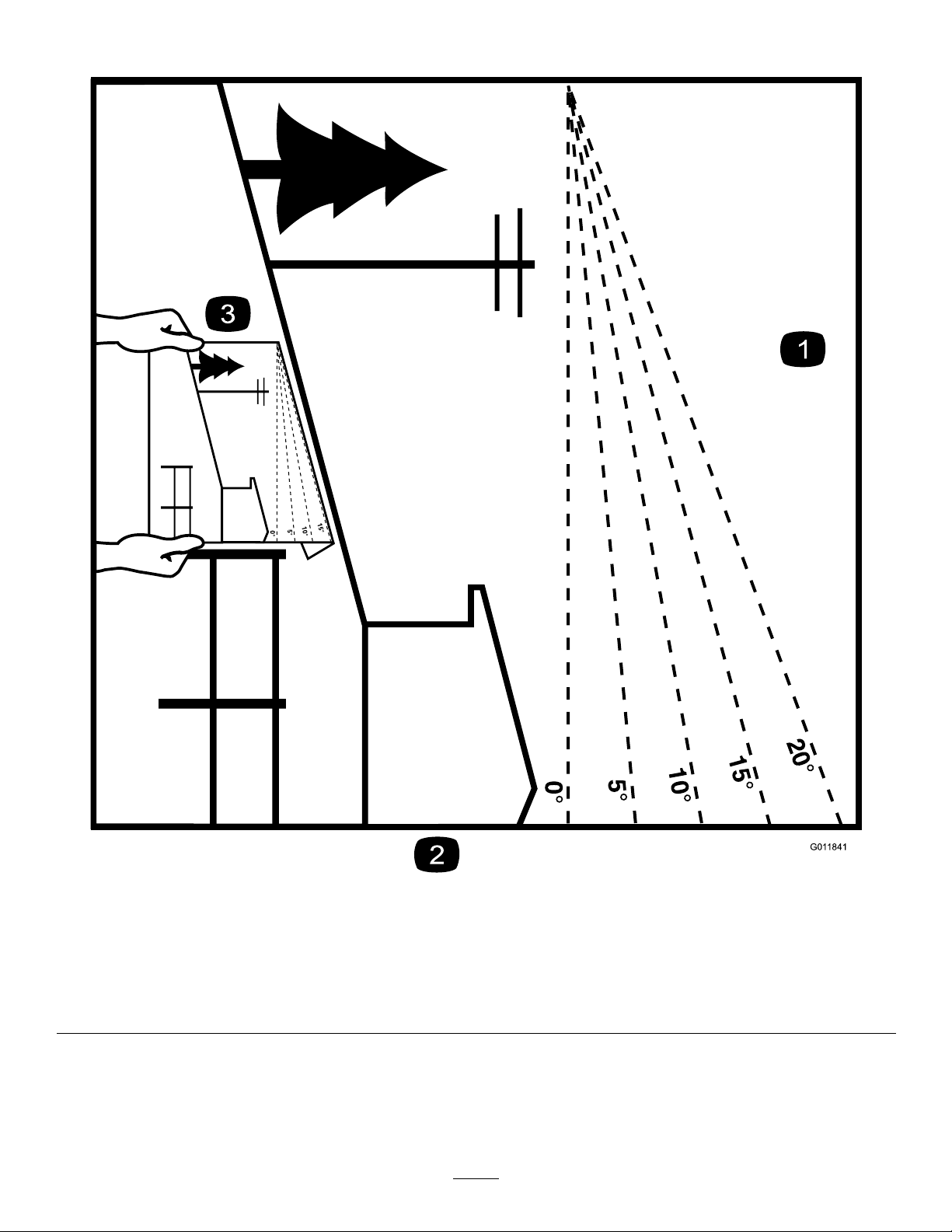
G011841
Figure2
Thispagemaybecopiedforpersonaluse.
1.Themaximumslopeyoucansafelyoperatethemachineonis20degrees.Usetheslopecharttodeterminethedegreeofslope
ofhillsbeforeoperating.Donotoperatethismachineonaslopegreaterthan20degrees.Foldalongtheappropriateline
tomatchtherecommendedslope.
2.Alignthisedgewithaverticalsurface,atree,building,fencepole,etc.
3.Exampleofhowtocompareslopewithfoldededge.
7
Page 8
SafetyandInstructional
Decals
Safetydecalsandinstructionsareeasilyvisibletotheoperatorandarelocatednearanyareaof
potentialdanger.Replaceanydecalthatisdamagedorlost.
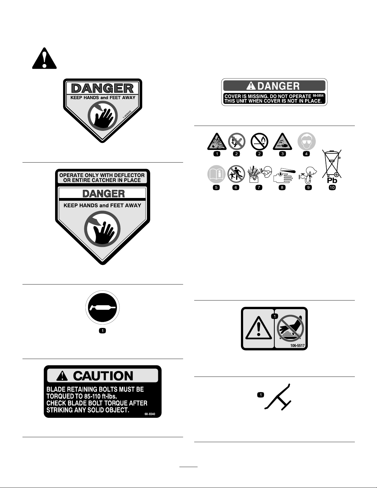
98-5954
1-403005
BatterySymbols
Someorallofthesesymbolsareonyourbattery
1.Explosionhazard
2.Nore,opename,or
smoking.
3.Causticliquid/chemical
burnhazard
4.Weareyeprotection9.Flusheyesimmediately
54-9220
5.ReadtheOperator’s
Manual.
6.Keepbystandersasafe
distancefromthebattery.
7.Weareyeprotection;
explosivegasescan
causeblindnessandother
injuries
8.Batteryacidcancause
blindnessorsevereburns.
withwaterandgetmedical
helpfast.
10.Containslead;donot
discard.
58-6520
1.Grease
106-5517
1.Warning–DoNottouchthehotsurface.
Manufacturer’sMark
68-8340
1.Indicatesthebladeisidentiedasapartfromtheoriginal
machinemanufacturer.
8
Page 9
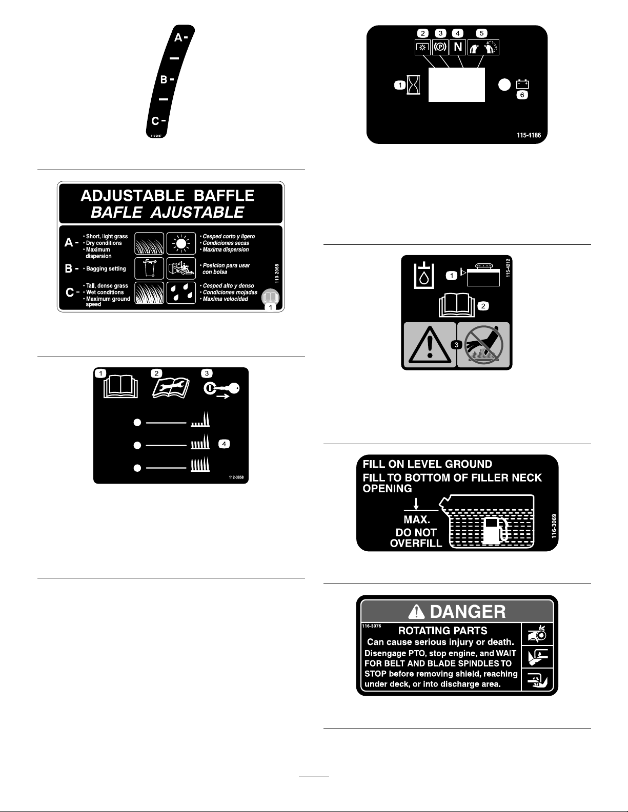
110-2067
110-2068
1.ReadtheOperator’sManual.
115-4186
1.Interval
2.PowerT ake-off(PTO)
3.Parkingbrake
4.Neutral
5.Operatorpresenceswitch
6.Battery
115-4212
1.Hydraulicoillevel3.Warning—donottouch
thehotsurface.
2.ReadtheOperator’s
Manual.
1.ReadtheOperator’s
Manual.
2.Readtheinstructions
beforeservicingor
performingmaintenance.
112-3858
3.Removetheignitionkey
beforeadjustingtheheight
ofcut.
4.Heightofcutsettings.
116-3069
116-3076
9
Page 10
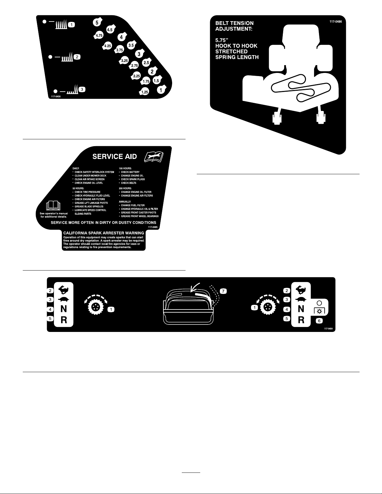
117-0456
1.Heightofcut(HOC)—high3.Heightofcut(HOC)—low
2.Heightofcut
(HOC)—medium
117-0485
117-0486
1.Tractioncontrol
2.Fast4.Neutral
117-0454
3.Slow
5.Reverse
6.PowerT ake-off
(PTO)—disengage
7.Operatorpresenceswitch
10
Page 11
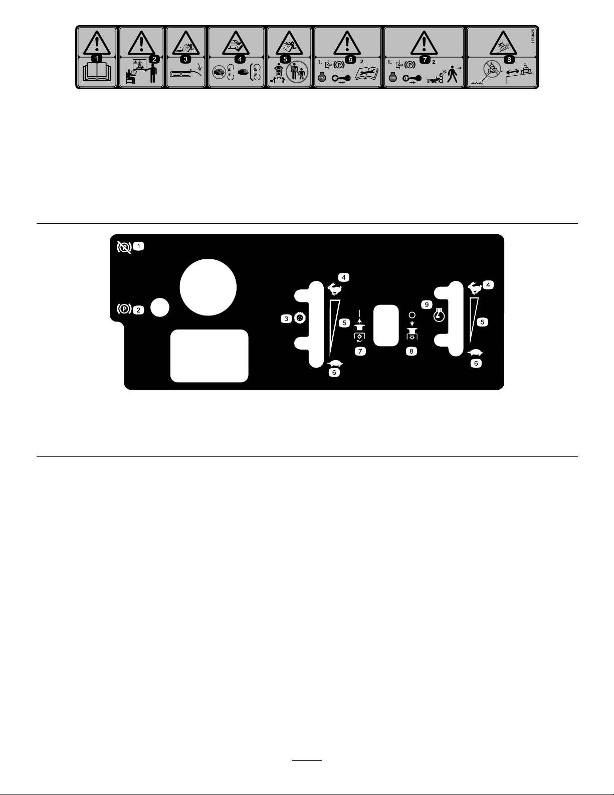
117–3626
1.Warning—readtheOperator’sManual.5.Thrownobjecthazard—keepbystandersasafedistancefrom
2.Warning—donotoperatethismachineunlessyouaretrained.6.Warning—engagetheparkingbrake,stoptheengine
3.Thrownobjecthazard—keepdeectorinplace.
4.Cutting,dismembermenthazardofhandorfoot—stayaway
frommovingpartsandkeepallguardsandshieldsinplace.
themachine.
andremovethesparkplugwirebeforeperformingany
maintenanceonthemachine.
7.Warning—engagetheparkingbrakeandstoptheengine
beforeleavingthemachine.
8.Slidingandlossofcontrolhazard—donotoperatethe
machineneardrop-offsorwater;keepasafedistancefrom
drop-offs.
1.Parkingbrake—disengage4.Fast
2.Parkingbrake—engage
3.Tractioncontrol
119-7245
7.PowerTake-off(PTO)—engage
5.Continuousvariablesetting8.PowerTake-off(PTO)—disengage
6.Slow
9.Enginespeed
11
Page 12
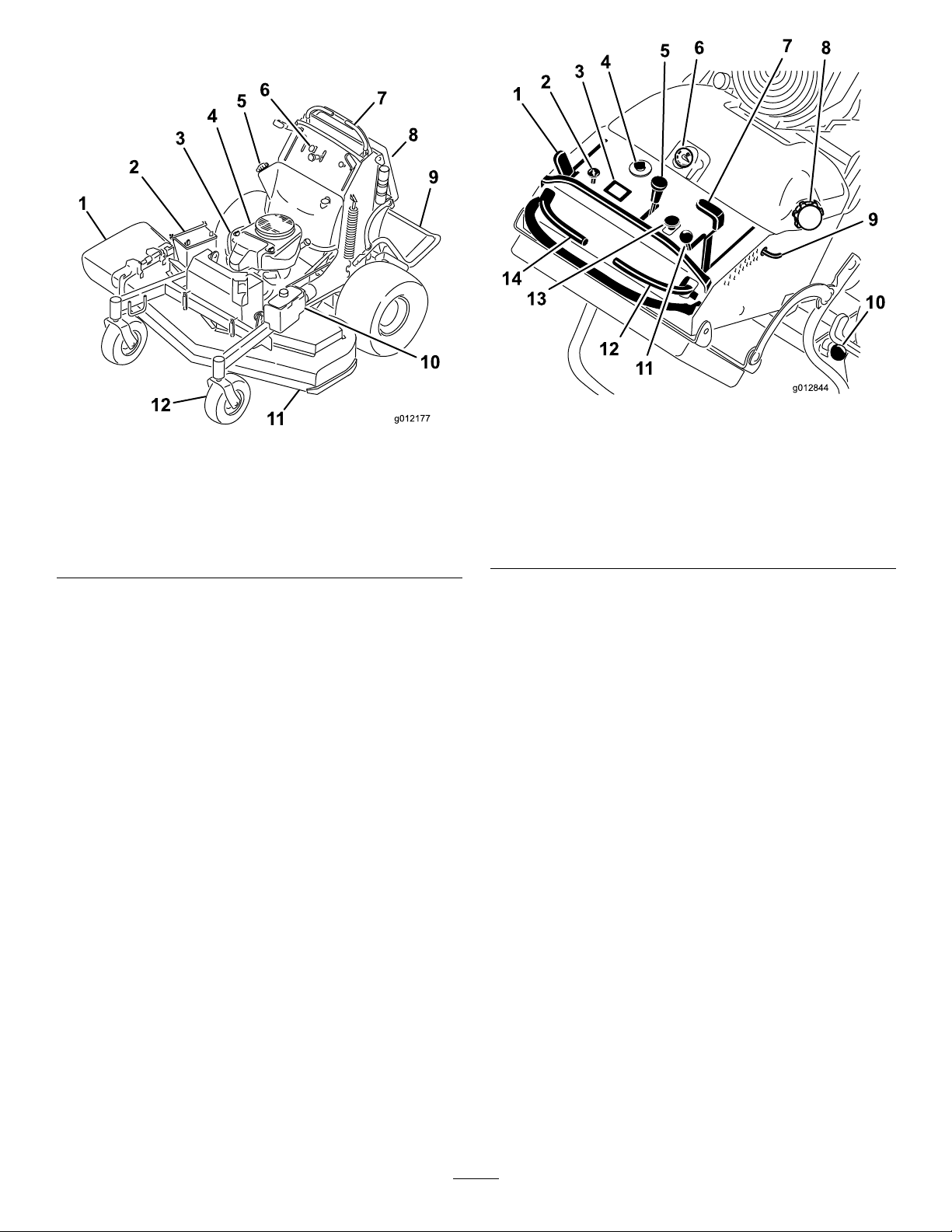
ProductOverview
g012844
3
4
5
6
7
8
9
10
11
12
13
14
Figure3
1.Sidedischargechute7.Controllevers
2.Battery8.Manualtube
3.Engine
4.Fuelshut-offvalve
5.Fueltank11.Mowerdeck
6.Controls
9.Platform(downposition)
10.Hydraulictank
12.Frontcasterwheel
Figure4
1.Parkingbrakelever8.Fuelcap
2.Choke9.Height-of-cutpin
3.Hourmeter
4.Ignitionswitch11.Throttlecontrol
5.Speedcontrollever
6.Fuelgauge
7.Height-of-cutlever14.Leftmotioncontrollever
10.Platformlatch
12.Rightmotioncontrollever
13.Bladecontrolswitch(PTO)
Controls
Becomefamiliarwithallthecontrols(Figure4)before
youstarttheengineandoperatethemachine.
HourMeter
Thehourmeterrecordsthenumberofhourstheengine
hasoperated.Itoperateswhentheengineisrunning.
Usethesetimesforschedulingregularmaintenance
(Figure5).
FuelGauge
Thefuelgaugeislocatedonthetop,middleofthetank
Figure4).
(
SafetyInterlockIndicators
Therearesymbolsonthehourmeterandindicatewith
ablacktrianglethattheinterlockcomponentisinthe
correctposition(Figure5).
BatteryIndicatorLight
IftheignitionkeyisturnedtotheOnpositionforafew
seconds,thebatteryvoltagewillbedisplayedinthearea
wherethehoursarenormallydisplayed.
Thebatterylightturnsonwhentheignitionisturned
onandwhenthechargeisbelowthecorrectoperating
level(Figure5).
12
Page 13

Figure5
1.Safetyinterlocksymbols
2.Batterylight
3.Hourmeter
SpeedControlLever
Thismachinehasavariablespeedcontrol.Thiscontrols
howfastorslowthemachinewilltravel.
ThrottleControl
enhanceandexpanditscapabilities.Contactyour
AuthorizedServiceDealerorDistributororgoto
www.Toro.comforalistofallapprovedattachments
andaccessories.
Specications
Note:Specicationsanddesignaresubjecttochange
withoutnotice.
48inchmowers:
Widthwithdeectordown63.5inches(161.3cm)
Lengthwithplatformdown74inches(188cm)
Lengthwithplatformup58inches(147.3cm)
Height
Weightwith20hpengine
Weightwith24hpengine
48inches(121.9cm)
881(399.6kg)
888(402.8kg)
ThethrottlecontrolisvariablebetweenFastandSlow.
Choke
Usethechoketostartacoldengine.
BladeControlSwitch(PTO)
Thebladecontrolswitch(PTO)isusedtoengage
theelectricclutchtodrivethemowerbladeswiththe
rightsidemotioncontrolleverinthecenter,un-locked
position.Pulltheswitchuptoengagethebladesand
release.Todisengagetheblades,pushthebladecontrol
switch(PTO)downormoveorreleasetherightside
motioncontrolleverintotheneutrallockposition.
IgnitionSwitch
Thisswitchisusedtostartthemowerengineandhas
threepositions:Off,RunandStart.
MotionControlLevers
Themotioncontrolleversareusedtodrivethemachine
forward,reverse,andturneitherdirection.
52inchmowers:
Widthwithdeectordown67.5inches(171.4cm)
Lengthwithplatformdown74inches(188cm)
Lengthwithplatformup58inches(147.3cm)
Height
Weightwith20hpengine
Weightwith24hpengine
60inchmowers:
Widthwithdeectordown75.67inches(192.2cm)
Lengthwithplatformdown74inches(188cm)
Lengthwithplatformup58inches(147.3cm)
Height
Weightwith25hpengine
Weightwith26hpengine
48inches(121.9cm)
883(400.5kg)
900(408.2kg)
48inches(121.9cm)
920(417.3kg)
925(419.5kg)
FuelShut-offValve
Closethefuelshut-offvalve(ontherightsideofthe
engine)whentransportingorstoringthemower.
Attachments/Accessories
AselectionofToroapprovedattachmentsand
accessoriesareavailableforusewiththemachineto
13
Page 14

Operation
Note:Determinetheleftandrightsidesofthe
machinefromthenormaloperatingposition.
AddingFuel
UseUnleadedRegularGasolinesuitablefor
automotiveuse(85pumpoctaneminimum).Leaded
regulargasolinemaybeusedifunleadedregularisnot
available.
Important:Neverusemethanol,gasoline
containingmethanol,orgasoholcontainingmore
than10%ethanolbecausethefuelsystemcouldbe
damaged.Donotmixoilwithgasoline.
DANGER
Incertainconditions,gasolineisextremely
ammableandhighlyexplosive.Areorexplosion
fromgasolinecanburnyouandothersandcan
damageproperty.
•Fillthefueltankoutdoorsonlevelground,in
anopenarea,whentheengineiscold.Wipeup
anygasolinethatspills.
DANGER
Incertainconditionsduringfueling,static
electricitycanbereleasedcausingasparkwhich
canignitethegasolinevapors.Areorexplosion
fromgasolinecanburnyouandothersandcan
damageproperty.
•Alwaysplacegasolinecontainersontheground
awayfromyourvehiclebeforelling.
•Donotllgasolinecontainersinsideavehicle
oronatruckortrailerbedbecauseinterior
carpetsorplastictruckbedlinersmayinsulate
thecontainerandslowthelossofanystatic
charge.
•Whenpractical,removegas-powered
equipmentfromthetruckortrailerandrefuel
theequipmentwithitswheelsontheground.
•Ifthisisnotpossible,thenrefuelsuch
equipmentonatruckortrailerfromaportable
container,ratherthanfromagasolinedispenser
nozzle.
•Ifagasolinedispensernozzlemustbeused,
keepthenozzleincontactwiththerimofthe
fueltankorcontaineropeningatalltimesuntil
fuelingiscomplete.
•Neverllthefueltankinsideanenclosedtrailer.
•Donotllthefueltankcompletelyfull.Fill
thefueltanktothebottomofthellerneck.
Theemptyspaceinthetankallowsgasolineto
expand.Overllingmayresultinfuelleakage
ordamagetotheengineoremissionsystem(if
equipped).
•Neversmokewhenhandlinggasoline,andstay
awayfromanopenameorwheregasoline
fumesmaybeignitedbyaspark.
•Storegasolineinanapprovedcontainerand
keepitoutofthereachofchildren.Neverbuy
morethana30-daysupplyofgasoline.
•Donotoperatewithoutentireexhaustsystem
inplaceandinproperworkingcondition.
WARNING
Gasolineisharmfulorfatalifswallowed.
Long-termexposuretovaporscancauseserious
injuryandillness.
•Avoidprolongedbreathingofvapors.
•Keepfaceawayfromnozzleandgastankor
conditioneropening .
•Keepgasawayfromeyesandskin.
UsingStabilizer/Conditioner
Useafuelstabilizer/conditionerinthemachineto
providethefollowingbenets:
•Keepsgasolinefreshduringstorageof90daysor
less.Forlongerstorageitisrecommendedthatthe
fueltankbedrained.
•Cleanstheenginewhileitruns
•Eliminatesgum-likevarnishbuildupinthefuel
system,whichcauseshardstarting
Important:Donotusefueladditives
containingmethanolorethanol.
Addthecorrectamountofgas
stabilizer/conditionertothegas.
14
Page 15
Note:Afuelstabilizer/conditionerismost
2
4
3
G012565
1
5
effectivewhenmixedwithfreshgasoline.To
minimizethechanceofvarnishdepositsinthefuel
system,usefuelstabilizeratalltimes.
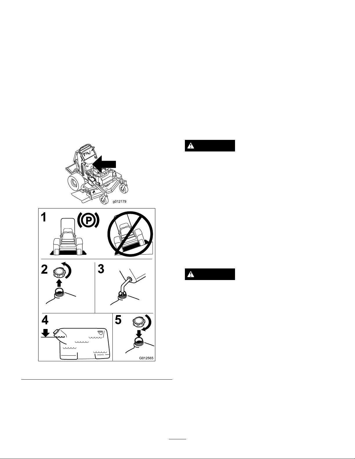
FillingtheFuelT ank
Note:Donotllthefueltankcompletelyfull.Fillthe
fueltanktothebottomofthellerneck.Theempty
spaceinthetankallowsthegasolinetoexpand.
1.Parkthemachineonlevelground.
2.Shuttheengineoffandsettheparkingbrake.
3.Cleanaroundthefueltankcap.
4.Fillthefueltanktothebottomofthellerneck.
Ensurethereisemptyspaceinthetanktoallowthe
gasolinetoexpand
Figure6.
BreakingInaNewMachine
Newenginestaketimetodevelopfullpower.Mower
decksanddrivesystemshavehigherfrictionwhennew,
placingadditionalloadontheengine.Allow40to50
hoursofbreak-intimefornewmachinestodevelopfull
powerandbestperformance.
ThinkSafetyFirst
Carefullyreadallthesafetyinstructionsanddecalsin
thesafetysection.Knowingthisinformationcould
helpyouoranybystandersavoidinjury.
Theuseofprotectiveequipmentforeyes,hearing,feet
andheadisrecommended.
CAUTION
Thismachineproducessoundlevelsinexcessof
85dBAattheoperator’searandcancausehearing
lossthroughextendedperiodsofexposure.
Wearhearingprotectionwhenoperatingthis
machine.
Figure6
OperatingtheParkingBrake
Alwayssettheparkingbrakewhenyoustopthe
machineorleaveitunattended.Beforeeachuse,check
theparkingbrakeforproperoperation.
Iftheparkingbrakedoesnotholdsecurely,adjustit.
RefertoServicingtheParkingBrake.
CAUTION
Childrenorbystandersmaybeinjuredifthey
moveorattempttooperatethemachinewhileit
isunattended.
Alwaysremovetheignitionkeyandsettheparking
brakewhenleavingthemachineunattended,even
ifjustforafewminutes.
SettingtheParkingBrake
Pulltheparkingbrakeleverrearwardandoverinto
engagedposition(Figure7).
CheckingtheEngineOilLevel
Beforeyoustarttheengineandusethemachine,check
theoillevelintheenginecrankcase;refertoChecking
OilLevelinEngineMaintenance.
15
Page 16
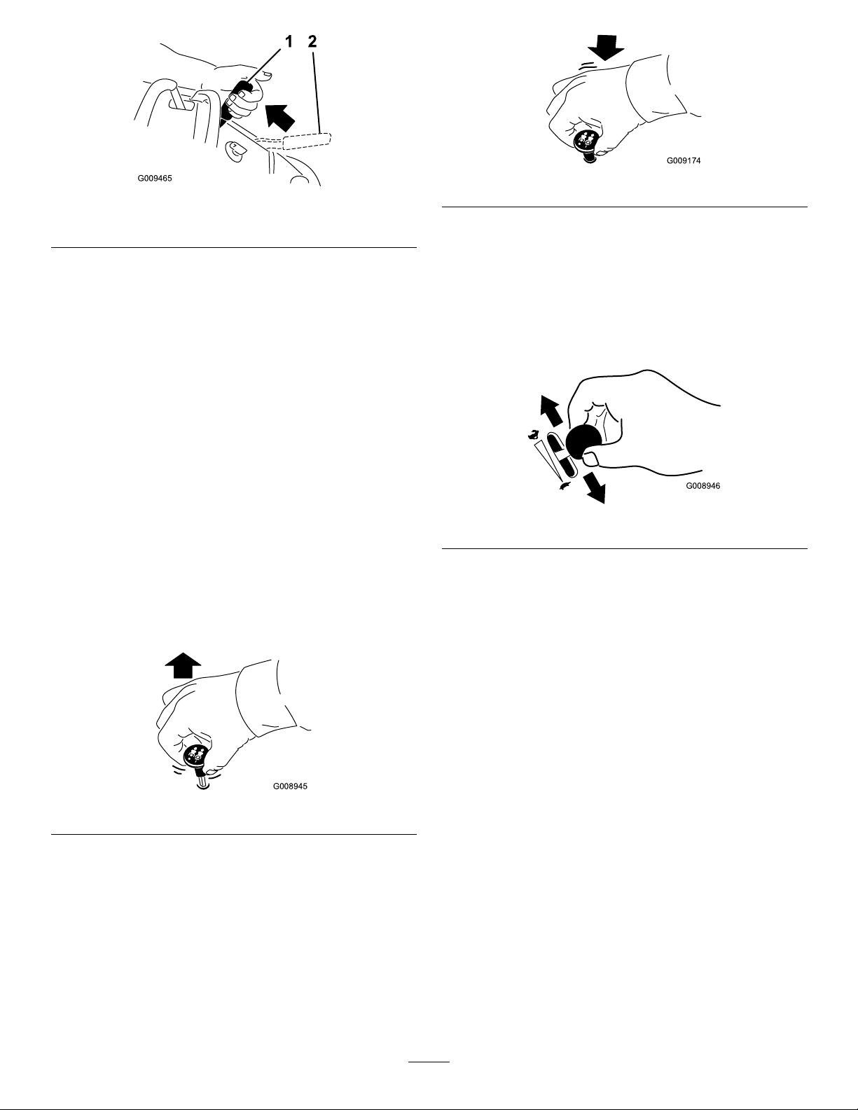
Figure7
G008945
G009174
G008946
1.Parkingbrakeengaged2.Parkingbrakereleased
Figure9
OperatingtheThrottle
ReleasingtheParkingBrake
Pullthebrakeleverbackandoverintotheslotand
pushtheparkingbrakeleverforward.
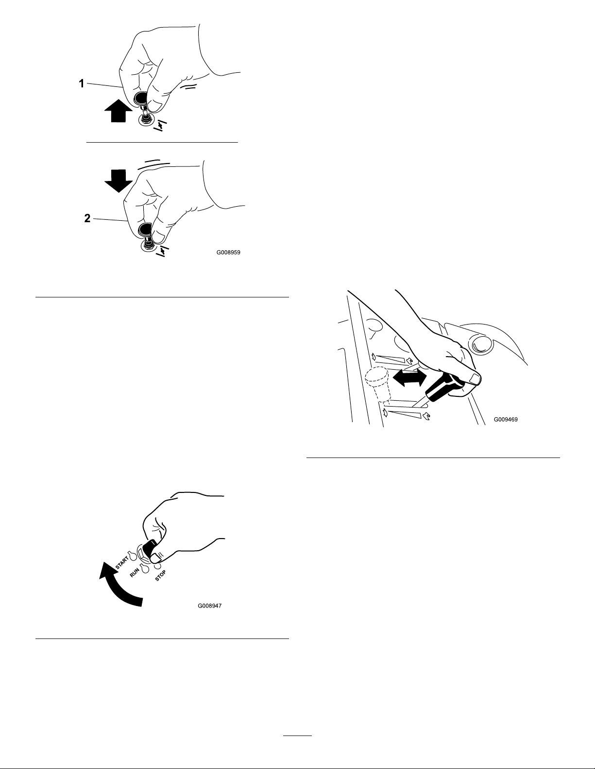
OperatingtheMowerBlade
ControlSwitch(PTO)
Thebladecontrolswitch(PTO)isusedinconjunction
withtherightsidemotioncontrollevertoengageand
disengagethemowerblades.
EngagingtheMowerBlades(PTO)
1.Toengagethemowerblades,movetherightside
motioncontrollevertothecenter,un-locked
position.
2.Pullthebladecontrolswitch(PTO)upandrelease
itwhileholdingdowntherightsidemotioncontrol
leverinthecenter,un-lockedposition.
ThethrottlecontrolcanbemovedbetweenFastand
Slowpositions(Figure10).
Alwaysusethefastpositionwhenturningonthe
mowerdeckwiththebladecontrolswitch(PTO).
Figure10
OperatingtheChoke
Usethechoketostartacoldengine.
1.Iftheengineiscold,usethechoketostartthe
engine.
Figure8
DisengagingtheMowerBlades(PTO)
Thefollowingaretwooptionsfordisengagingthe
mowerblades.
•Pushthebladecontrolswitch(PTO)downtothe
offposition.
•Movethemotioncontrolleverstoneutralandmove
therightsidemotioncontrolleverintotheneutral
lockposition.
2.Pulluponthechokeknobtoengagethechoke
beforeusingtheignitionswitch(
Figure11).
3.Pushdownonthechoketodisengagethechoke
aftertheenginehasstarted(Figure11).
16
Page 17
G008959
1
2
Figure11
START
RUN
STOP
G008947
1.On2.Off
UsingtheSpeedControl
Lever
Thismachinehasaspeedcontrolleverthatsets
themaximumgroundspeedofthemachine.This
canbeadjustedtotheoperator’sdesiredspeed.It
isrecommendedtousetheslowestspeedfornew
operator’s.
1.Movethespeedcontrollevertosetthedesired
speed.
•Fullforwardhasquickresponseandmaximum
speed.
•Fullrearwardhassmoothresponseandslower
speed.
2.Movethecontrolleverstodrivethemachine.The
controlleversmaybepushedforwardtothefront
referencebarwhilethespeedofthemachineis
controlledbythespeedcontrollever.
OperatingtheIgnitionSwitch
1.TurntheignitionkeytotheStartposition
(Figure12).Whentheenginesstarts,releasethekey.
Important:Donotengagestarterformore
than5secondsatatime.Iftheenginefails
tostartallowa15secondcool-downperiod
betweenattempts.Failuretofollowthese
instructionscanburnoutthestartermotor.
Figure13
Note:Additionalstartingcyclesmayberequired
whenstartingtheengineforthersttimeafterthe
fuelsystemhasbeenwithoutfuelcompletely.
UsingtheFuelShut-OffValve
Closethefuelshut-offvalvefortransport,maintenance,
andstorage(
Ensurethefuelshut-offvalveisopenwhenstarting
theengine.
Figure14).
Figure12
2.Turntheignitionkeytostoptostoptheengine.
17
Page 18
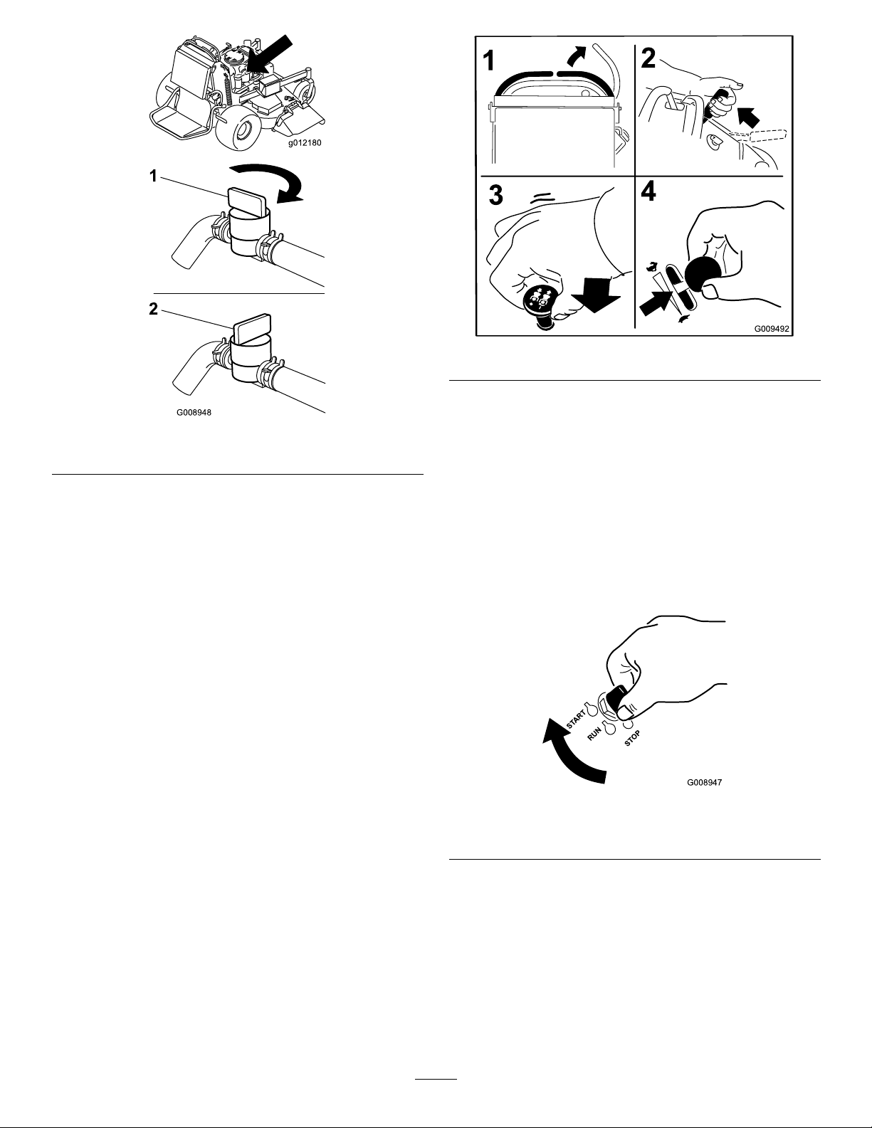
G008948
1
2
Figure14
START
RUN
STOP
G008947
1.On2.Off
StartingandStoppingthe
Engine
StartingtheEngine
1.Connectthewirestothesparkplugs.
2.Openthefuelvalve.
3.Movetherightmotioncontrollevertoneutral
lockedposition.
4.Settheparkingbrake;refertoSettingtheParking
Brake.
Figure15
7.TurntheignitionkeytotheStartposition
(Figure12).Whentheenginesstarts,releasethekey.
Important:Donotengagestarterformore
than5secondsatatime.Iftheenginefails
tostartallowa15secondcool-downperiod
betweenattempts.Failuretofollowthese
instructionscanburnoutthestartermotor.
Note:Additionalstartingcyclesmayberequired
whenstartingtheengineforthersttimeafterthe
fuelsystemhasbeenwithoutfuelcompletely.
5.Movethebladecontrolswitch(PTO)totheOff
position.
Figure16
6.MovethethrottlelevermidwaybetweentheSlow
andFastpositions.
1.Off3.Start
2.Run
Note:Awarmorhotenginemaynotrequire
choking.
18
Page 19
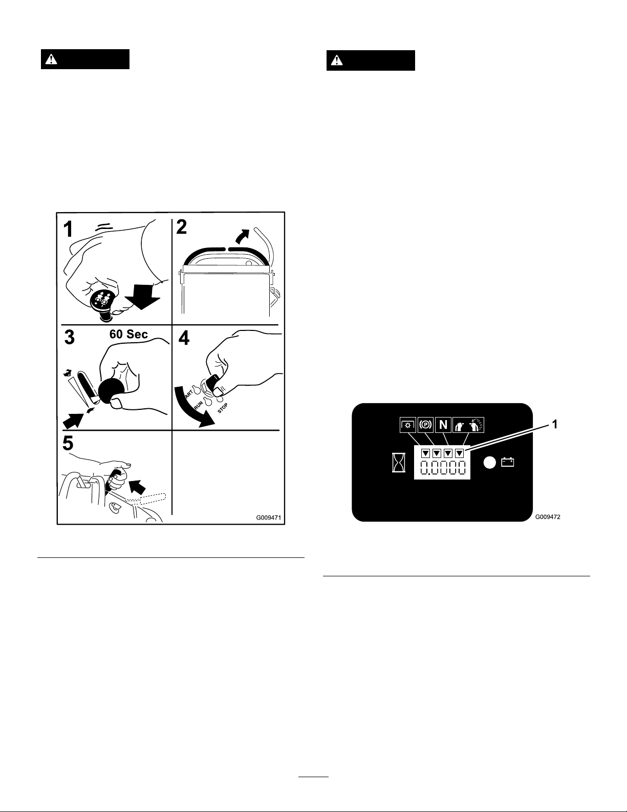
StoppingtheEngine
TheSafetyInterlockSystem
CAUTION
Childrenorbystandersmaybeinjuredifthey
moveorattempttooperatethetractorwhileitis
unattended.
Alwaysremovetheignitionkeyandsettheparking
brakewhenleavingthemachineunattended,even
ifjustforafewminutes.
Lettheengineidleatslowthrottle(turtle)for60
secondsbeforeturningtheignitionswitchoff.
CAUTION
Ifsafetyinterlockswitchesaredisconnectedor
damagedthemachinecouldoperateunexpectedly
causingpersonalinjury.
•Donottamperwiththeinterlockswitches.
•Checktheoperationoftheinterlockswitches
dailyandreplaceanydamagedswitchesbefore
operatingthemachine.
UnderstandingtheSafetyInterlock
System
Thesafetyinterlocksystemisdesignedtopreventthe
mowerbladesfromrotatingunless:
•Therightsidemotioncontrolleverismovedtothe
center,un-lockedposition.
•Thebladecontrolswitch(PTO)ispulledon.
Thesafetyinterlocksystemisdesignedtostopthe
mowerbladesifyoumoveorreleasetherightside
motioncontrolleverintotheneutrallockposition.
Thehourmeterhassymbolstonotifytheuserwhen
theinterlockcomponentisinthecorrectposition.
Whenthecomponentisinthecorrectposition,a
trianglewilllightupinthecorrespondingsquare.
Figure17
Important:Makesurefuelshutoffvalveisclosed
beforetransportingorstoringthemachine,asfuel
leakagemayoccur.Beforestoringthemachine,
pullwireoffsparkplug(s)topreventpossibilityof
accidentalstarting.
Figure18
1.Triangleslightupwhentheinterlockcomponentsareinthe
correctposition
TestingtheSafetyInterlockSystem
ServiceInterval:Beforeeachuseordaily
Testthesafetyinterlocksystembeforeyouusethe
machineeachtime.
Note:Ifthesafetysystemdoesnotoperateas
describedbelow,haveanAuthorizedServiceDealer
repairthesafetysystemimmediately .
1.Starttheengine;refertoStartingandStoppingthe
EngineinOperation(page14).
2.Settheparkingbrake.
19
Page 20

3.Movetherightsidemotioncontrollevertothe
center,un-lockedposition.Thebladesshould
notrotate.
4.Movethemotioncontrolleversforward.The
engineshouldkill.
5.Starttheengineandreleasetheparkingbrake.
6.Movetherightsidemotioncontrollevertothe
center,un-lockedposition.
7.Continueholdingtherightsidemotioncontrollever
inthecenter,un-lockedpositionandpulluponthe
bladecontrolswitch(PTO)andrelease.Theclutch
shouldengageandthemowerbladesbeginrotating.
8.Moveorreleasetherightsidemotioncontrollever
intotheneutrallockposition.Thebladesshould
stoprotatingandtheenginecontinuestorun.
9.Pushthebladecontrolswitchdownandmove
therightsidemotioncontrollevertothecenter,
un-lockedposition.
10.Continueholdingtherightsidemotioncontrollever
inthecenter,un-lockedpositionandpulluponthe
bladecontrolswitch(PTO)andrelease.Theclutch
shouldengageandthemowerbladesbeginrotating.
11.Pushthebladecontrolswitch(PTO)downtothe
offposition.Thebladesshouldstoprotating.
12.Withtheenginerunning,pullupthebladecontrol
switch(PTO)andreleasewithoutholdingright
sidemotioncontrollevertothecenter,un-locked
position.Thebladesshouldnotrotate.
OperatingtheMachinewiththe
PlatformUp
Operatingthemachinewiththeplatformupis
recommendedwhen:
•Mowingneardrop-off’s
•Mowingsmallareaswherethemachineistoolong
•Areaswithlowoverhangingbranchesorobstacles
•Loadingthemachinefortransport
•Drivingupslopes
Toraisetheplatform,pullthebackoftheplatformup
sothelatchpinandknoblockitintoplace.Pushittight
againstthecushionforthelatchpintolockintoplace.
OperatingtheMachinewiththe
PlatformDown
Operatingthemachinewiththeplatformdownis
recommendedwhen:
•Mowingmostareas
•Drivingacrossslopes
•Drivingdownslopes
Tolowertheplatform,pushtheplatformforward
againstthecushiontoreleasepressureonthelatchpin
andthenpulltheknoboutandlowertheplatform.
WARNING
Theoperatorplatformisheavyandmaycause
injurywhenloweringandraisingtheoperator
platform.Theplatformmaysuddenlydropifnot
supportedwhenthelatchpinispulledout.
•Donotputhandsorngersintheplatform
pivotareawhenloweringorraisingtheoperator
platform.
•Makesuretheplatformissupportedwhenthe
latchpinispulledout.
•Makesurethelatchsecurestheplatformwhen
foldingitintheupposition.Pushittight
againstthecushionforthelatchpintolock
intoplace.
•Keepbystandersawaywhenraisingorlowering
theplatform.
OperatingthePlatform
Themachinecanbeusedwiththeplatformintheup
ordownposition.Itistheoperator’spreferenceon
whichpositiontouse.
20
Page 21

Figure19
G012182
4
5
1
2
3
3 4
1.Platformup
2.Platformdown
3.Pulltheknobouttorelease
theplatform
DrivingForwardorBackward
Thethrottlecontrolregulatestheenginespeedas
measuredinrpm(revolutionsperminute).Place
thethrottlecontrolinthefastpositionforbest
performance.Alwaysoperateinthefullthrottle
positionwhenmowing.
Figure20
1.Frontreferencebar
2.Leftcontrollever
3.Rearreferencebar
4.Rightcontrollever
5.Rightcontrolleverinthe
neutrallockposition
3.Togoforward,movethespeedcontrollevertothe
desiredspeed.
4.Slowlypushthemotioncontrolleversforward
(Figure21).
Note:Theenginewillkillifamotioncontrollever
ismovedwiththeparkingbrakeengaged.
Thefartheryoumovethemotioncontrolleversin
eitherdirection,thefasterthemachinewillmovein
thatdirection.
Tostop,pullthemotioncontrolleversbacktothe
neutralposition.
CAUTION
Machinecanspinveryrapidly.Operatormaylose
controlofmachineandcausepersonalinjuryor
damagetomachine.
Slowthemachinedownbeforemakingsharpturns.
DrivingForward
1.Releasetheparkingbrake;refertoReleasingthe
ParkingBrakeinOperation.
2.Movetherightsidemotioncontrollevertothe
center,un-lockedposition.
21
Page 22

Figure21
Settheparkingbrakewhenyouleavethemachine;refer
toSettingtheParkingBrakeinOperation.Remember
toremovethekeyfromtheignitionswitch.
CAUTION
Childrenorbystandersmaybeinjuredifthey
moveorattempttooperatethetractorwhileitis
unattended.
Alwaysremovetheignitionkeyandsettheparking
brakewhenleavingthemachineunattended,even
ifjustforafewminutes.
PushingtheMachinebyHand
Theby-passvalvesallowthemachinetobepushedby
handwithouttheenginerunning.
Important:Alwayspushthemachinebyhand.
Nevertowthemachinebecausehydraulicdamage
mayoccur.
DrivingBackward
1.Movetherightsidemotioncontrollevertothe
center,un-lockedposition.
2.Slowlypullthemotioncontrolleversrearward
Figure22).
(
Figure22
ToPushtheMachine
1.DisengagethePTO,movethemotioncontrol
leverstotheneutrallockedpositionandsetthe
parkingbrake.
2.Opentheby-passvalveonbothpumpsbyturning
themcounterclockwise1to2turns.Thisallows
hydraulicuidtoby-passthepumpsandthewheels
toturn(
Note:Rotatetheby-passvalvesamaximumof2
turnssothevalvedoesnotcomeoutofthebody
causinguidtorunout.
Figure23).
StoppingtheMachine
Tostopthemachine,movethemotioncontrolleversto
neutral,movetherightsidemotioncontrolleverinto
theneutrallockposition,disengagethepowertakeoff
(PTO),andturntheignitionkeytooff.
Figure23
1.Pumpby-passvalve
3.Releasetheparkingbrake.
22
Page 23

4.Pushthemachinetothedesiredlocation.
5.Settheparkingbrake.
6.Closetheby-passvalves,butdonotovertighten
them.
Important:Donotstartoroperatethe
machinewiththeby-passvalvesopen.Damage
tosystemmayoccur.
TransportingMachines
Useaheavy-dutytrailerortrucktotransportthe
machine.Ensurethatthetrailerortruckhasall
necessarybrakes,lighting,andmarkingasrequiredby
law .Pleasecarefullyreadallthesafetyinstructions.
Knowingthisinformationcouldhelpyou,yourfamily,
petsorbystandersavoidinjury.
Totransportthemachine:
1.Raisetheplatformofthemachinebeforedrivingup
ontothetrailerortruck.
2.Ifusingatrailer,connectittothetowingvehicle
andconnectthesafetychains.
3.Ifapplicable,connectthetrailerbrakes.
4.Loadthemachineontothetrailerortruck.
5.Stoptheengine,removethekey,setthebrake,and
closethefuelvalve.
6.Usethemetaltiedownloopsonthemachineto
securelyfastenthemachinetothetrailerortruck
withstraps,chains,cable,orropes(
Figure24).
extendbeyondthereartiresisrecommendedinsteadof
individualrampsforeachsideoftheunit(Figure25).
Theplatformwhendownandlockedintoposition,
extendsbackbetweentherearwheelsandservesasa
stopfortippingbackward.Havingafullwidthramp
providesasurfacefortheplatformtocontactifthe
unitstartstotipbackward.Withtheplatformup,afull
widthrampprovidesasurfacetowalkonbehindthe
unit.Theoperatorshoulddetermineifitisbesttohave
theplatformupordownwhenloading,dependingon
conditions.Ifitisnotpossibletouseonefullwidth
ramp,useenoughindividualrampstosimulateafull
widthcontinuousramp.
Therampshouldbelongenoughsothattheangles
donotexceed20degrees(
maycausemowercomponentstogetcaughtastheunit
movesfromramptotrailerortruck.Steeperangles
mayalsocausetheunittotipbackward.Ifloadingon
ornearaslope,positionthetrailerortrucksoitison
thedownsideoftheslopeandtherampextendsupthe
slope.Thiswillminimizetherampangle.Thetraileror
truckshouldbeaslevelaspossible.
Important:DoNotattempttoturntheunitwhile
ontheramp;youmaylosecontrolanddriveoff
theside.
Avoidsuddenaccelerationwhendrivinguparampand
suddendecelerationwhenbackingdownaramp.Both
maneuverscancausetheunittotipbackward.
Figure25).Asteeperangle
WARNING
Loadingaunitontoatrailerortruckincreasesthe
possibilityofbackwardtip-overandcouldcause
seriousinjuryordeath.
Figure24
1.Tractionunittiedownloop
LoadingMachines
Useextremecautionwhenloadingunitsontrailersor
trucks.Onefullwidthrampthatiswideenoughto
•Useextremecautionwhenoperatingauniton
aramp.
•Useonlyasingle,fullwidthramp;DoNotuse
individualrampsforeachsideoftheunit.
•Ifindividualrampsmustbeused,useenough
rampstocreateanunbrokenrampsurface
widerthantheunit.
•Donotexceeda20degreeanglebetweenramp
andgroundorbetweenrampandtraileror
truck.
•Avoidsuddenaccelerationwhiledrivingunitup
aramptoavoidtippingbackward.
•Avoidsuddendecelerationwhilebackingunit
downaramptoavoidtippingbackward.
23
Page 24

Figure25
1.Trailer3.Notgreaterthan
20degrees
2.Fullwidthramp4.Fullwidthramp—sideview
SideDischargingorMulching
1.Movetheheight-of-cutlevertothetransport
position(allthewayup).
2.Selectaholeintheheight-of-cutbracket
correspondingtotheheight-of-cutdesiredand,
insertthepin(Figure26).
3.Lowertheheight-of-cutlevertothepin(Figure26).
Figure26
1.Height-of-cutholes3.Height-of-cutlever
2.Height-of-cutpin
theGrass
Thismowerhasahingedgrassdeectorthatdisperses
clippingstothesideanddowntowardtheturf.
DANGER
Withoutthegrassdeector,dischargecover,or
completegrasscatcherassemblymountedin
place,youandothersareexposedtobladecontact
andthrowndebris.Contactwithrotatingmower
blade(s)andthrowndebriswillcauseinjuryor
death.
•Neverremovethegrassdeectorfromthe
mowerbecausethegrassdeectorroutes
materialdowntowardtheturf.Ifthe
grassdeectoriseverdamaged,replaceit
immediately.
•Neverputyourhandsorfeetunderthemower.
•Nevertrytocleardischargeareaormower
bladesunlessyoureleasethebailandthepower
takeoff(PTO)isoff.Rotatetheignitionkeyto
Off.Alsoremovethekeyandpullthewire(s)
offthesparkplug(s).
AdjustingtheAnti-Scalp
Rollers(60inchMowerDecks
Only)
Wheneveryouchangetheheight-of-cut,itis
recommendedtoadjusttheheightoftheanti-scalp
rollers.
1.Disengagethebladecontrolswitch(PTO),move
themotioncontrolleverstotheneutrallocked
positionandsettheparkingbrake.
2.Stoptheengine,removethekey,andwaitforall
movingpartstostopbeforeleavingtheoperating
position.
3.Removethenutandboltpositiontheanti-scalp
rollersandinstallthenutandbolt.Ensurethe
spacersandbushingsareinstalledasshown.
AdjustingtheHeight-of-Cut
Theheight-of-cutcanbeadjustedfrom1to5inches
(25to127mm)in1/4inch(6mm)increments.
24
Page 25

Figure27
1.Bushing4.Bolt
2.Anti-scalproller5.Nut
3.Spacer
AdjustingtheFlowBafe
Themowerdischargeowcanbeadjustedfordifferent
typesofmowingconditions.Positionthecamlockand
bafetogivethebestqualityofcut.
1.DisengagethePTO,movethemotioncontrol
leverstotheneutrallockedpositionandsetthe
parkingbrake.
2.Stoptheengine,removethekey,andwaitforall
movingpartstostopbeforeleavingtheoperating
position.
3.Toadjustthecamlock,swingtheleveruptoloosen
thecamlock(
Figure28).
Figure28
1.Camlock
2.Lever
3.Rotatecamtoincreaseor
decreaselockingpressure
4.Slot
PositioningtheFlowBafe
Thefollowingguresareonlyrecommendationsfor
use.Adjustmentswillvarybygrasstype,moisture
content,andheightofgrass.
Note:Iftheenginepowerdrawsdownandthemower
groundspeedisthesame,openupthebafe.
PositionA
Thisisthefullrearposition(seeFigure29).The
suggesteduseforthispositionisafollows.
•Useforshort,lightgrassmowingconditions.
•Useindryconditions.
•Forsmallergrassclippings.
4.Adjustthebafeandcamlockintheslottothe
desireddischargeow .
5.Swingtheleverbackovertotightenthebafeand
camlock(Figure28).
6.Ifthecamdoesnotlockthebafeintoplaceoritis
tootight,loosentheleverandthenrotatethecam
lock.Adjustthecamlockuntilthedesiredlocking
pressureisachieved.
•Propelsgrassclippingsfartherawayfromthe
mower.
25
Page 26

Figure29
Figure31
PositionB
Usethispositionwhenbagging(Figure30).
Figure30
PositionC
UsingtheMid-SizeWeight
•Weightsareinstalledtoimprovehandling,balance
andimproveperformance.Weightscanbeaddedor
removedtocreateoptimizedperformanceunder
differentmowingconditionsandforoperator
preference.
•Itisrecommendedthatweightsbeaddedor
removedoneatatimeuntilthedesiredhandingand
balanceisachieved.
Note:ContactanAuthorizedServiceDealertoorder
aW eightKit.
WARNING
Excessiveweightchangescaneffecthandlingand
operationofthemachine.Thiscouldcauseserious
injurytoyouorbystanders.
Makeweightchangesissmallincrementsonly .
Evaluatethemoweraftereachweightchangeto
ensurethemachinecanbeoperatedsafely.
Thisisthefullopenposition.Thesuggestedusefor
thispositionisasfollows(Figure31).
•Useintall,densegrassmowingconditions.
•Useinwetconditions.
•Lowerstheenginepowerconsumption.
•Allowsincreasedgroundspeedinheavyconditions.
•ThispositionissimilartothebenetsoftheT oro
SFSmower.
26
Page 27

Maintenance
Note:Determinetheleftandrightsidesofthemachinefromthenormaloperatingposition.
RecommendedMaintenanceSchedule(s)
MaintenanceService
Interval
Aftertherst8hours
Beforeeachuseordaily
Every25hours
Every50hours
Every100hours
MaintenanceProcedure
•Changetheengineoil.
•Checkthehydraulicuidlevel.
•Changethehydrauliclter.
•Checkthesafetyinterlocksystem.
•Checktheengineoillevel.
•Cleantheairintakescreen.
•Checkthebrakes.
•Inspecttheblades.
•Cleanthemowerdeck.
•Cleanfoamaircleanerelement.
•Greasetheliftlinkage(moreoftenindirtyordustyconditions).
•Lubricatethespeedcontrollinkagerollers(moreoftenindirtyordustyconditions).
•Checkthepaperaircleanerelement.
•Checkthetirepressure.
•Checkthehydraulicuidlevel.
•Changetheengineoil.(moreoftenindirtyordustyconditions)
•Check,cleanandregapthesparkplug.
•Checkthebattery.
•Checkandcleanenginecoolingnsandshrouds.
•Checkthemowerdeckbelt.
•Checkthepumpdrivebelt.
•Checkthehydraulichoses.
Every200hours
Every250hours
Every500hours
Every800hours
Beforestorage
Yearly
Important:Refertoyour
•Greasethemowerdeckspindles(moreoftenindirtyordustyconditions).
•Replacethepaperaircleanerelement.
•Changetheengineoillter.
•ChangethehydrauliclterandhydraulicoilwhenusingMobil®1oil.
•Adjustthecasterpivotbearing.
•Checktheelectricclutch.
•ChangethehydrauliclterandhydraulicoilwhenusingT oro®HYPR-OIL™500
hydraulicoil.
•Changethehydrauliclter.
•Greasethefrontwheelbearings(moreoftenindirtyordustyconditions).
•Greasethefrontcasterpivots(moreoftenindirtyordustyconditions).
•Replacethefuellter.
•Paintchippedsurfaces.
•Performallmaintenanceprocedureslistedabovebeforestorage.
•Greasethefrontcasterpivots(moreoftenindirtyordustyconditions).
•Lubricatethecasterwheelhubs
Engine Operator’ s Man ual
foradditionalmaintenanceprocedures.
27
Page 28

CAUTION
Ifyouleavethekeyintheignitionswitch,someonecouldaccidentlystarttheengineandseriouslyinjure
youorotherbystanders.
Removethekeyfromtheignitionanddisconnectthesparkplugwiresfromthesparkplugsbeforeyoudo
anymaintenance.Setthewiresasidesothattheydonotaccidentallycontactthesparkplugs.
Premaintenance
Procedures
RaisingtheMowerforAccess
Thefrontofthemowercanberaisedandsupportedon
itsbackforaccessunderthemachineformaintenance.
1.Raisetheplatform.RefertoOperatingthePlatform
inOperation.
2.Removethebattery.
Figure32
1.Wingnut4.Positivebatterycable
2.Batterycover5.Battery
3.Negativebatterycable
3.Drainthefuelfromthefueltank.RefertoDraining
theFuelTankinMaintenance.
4.Removethecapofthehydraulictankandplace
apieceofplasticovertheopeningandinstallthe
hydrauliccap.Thiswillsealthehydraulictankand
preventitfromleakingout.
Figure33
1.Cap
2.Pieceofplastic
5.Withtwopeople,raisethefrontofthemowersoit
restsonthedrivetiresandtheplatformintheup
position.
6.Performanymaintenanceonthemachine.
7.Withtwopeople,lowerthefrontofthemowerto
theground.
8.Removetheplasticunderthehydraulictankcap.
9.Installthebatteryforthemachine.
3.Hydraulictank
28
Page 29

Figure34
1.Removebattery
2.Withtwopeople,liftthe
frontendofthemower
(ensuretheplatformisup)
ReleasetheCushionforRear
Access
Thecushioncanbereleasedforrearaccesstothe
machineformaintenanceoradjustment.
1.Lowertheplatform.
2.Removethehairpincotterpinsoneachsideofthe
cushion.
3.Slidethelargewasherswithplasticbushingstothe
inside.
4.Removethecushionandlowerittotheplatform.
5.Performanymaintenanceoradjustmentonthe
machine.
6.Raisethecushionandslideitontothepinsonboth
sidesofthemachine(Figure35).
1.Plasticbushingwithlarge
washer
2.Cushionbracketwithkey
hole
Figure35
3.Hairpincotterpin
7.Slidethelargewashersplasticbushingsintothe
cushionbracketandsecurethemwithahairpin
cotterpin(
Figure35).
29
Page 30

Lubrication
GreasewithNo.2generalpurposelithiumbaseor
molybdenumbasegrease.
Lubricatethetractionrollerswithadrylubricant
(PTFE).
HowtoGrease
1.DisengagethePTOandsettheparkingbrake.
2.Stoptheengine,removethekey ,andwaitforall
movingpartstostopbeforeleavingtheoperating
position.
3.Cleanthegreasettingswitharag.Makesureto
scrapeanypaintoffthefrontofthetting(s).
4.Connectagreaseguntothetting.Pumpgrease
intothettingsuntilgreasebeginstooozeoutof
thebearings.
5.Wipeupanyexcessgrease.
Figure36
LubricatingtheMachine
ServiceInterval:Every50hours—Greasethelift
linkage(moreoftenindirtyordusty
conditions).
Every50hours—Lubricatethespeed
controllinkagerollers(moreoftenin
dirtyordustyconditions).
Every200hours—Greasethemower
deckspindles(moreoftenindirtyor
dustyconditions).
Every800hours/Y early(whichever
comesrst)—Greasethefrontwheel
bearings(moreoftenindirtyordusty
conditions).
Every800hours/Y early(whichever
comesrst)—Greasethefrontcaster
pivots(moreoftenindirtyordusty
conditions).
Usethefollowinggraphicsforlocatingthegreasepoints.
Figure37
Figure38
Lubricatethespeedcontrollinkagerollerswithadry
PTFE(Polytetrauoroethylene)lubricant.
30
Page 31

Important:UseonlyadryPTFE
g013192
(Polytetrauoroethylene)lubricant.Donot
useawetoillm,whichwillattractdustanddirt.
Figure40
1.Sealguard2.Spacernutwithwrench
ats
Figure39
GreasingtheFrontCaster
Pivots
ServiceInterval:Yearly
Lubricatethefrontcasterpivotsonceayear.
1.Removethedustcapandadjustthecasterpivots.
Keepthedustcapoffuntilgreasingisdone.Referto
AdjustingtheCasterPivotBearinginMaintenance
Section.
2.Removethehexplug.Threadagreasezerkintothe
hole.
3.Pumpgreaseintothezerkuntilitoozesoutaround
thetopbearing.
4.Removethegreasezerkinthehole.Installthehex
plugandcap.
LubricateCasterWheelHubs
ServiceInterval:Yearly
2.Removethecasterwheelfromthecasterforks.
3.Removethesealguardsfromthewheelhub.
4.Removeoneofthespacernutsfromtheaxle
assemblyinthecasterwheel.Notethatthread
lockingadhesivehasbeenappliedtolockthespacer
nutstotheaxle.Removetheaxle(withtheother
spacernutstillassembledtoit)fromthewheel
assembly.
5.Pryoutseals,andinspectbearingsforwearor
damageandreplaceifnecessary.
6.Packthebearingswithageneral-purposegrease.
7.Insertonebearing,onenewsealintothewheel.
Note:Thesealsmustbereplaced.
8.Iftheaxleassemblyhashadbothspacernuts
removed(orbrokenloose),applyathreadlocking
adhesivetoonespacernutandthreadontotheaxle
withthewrenchatsfacingoutward.DoNotthread
spacernutallofthewayontotheendoftheaxle.
Leaveapproximately1/8inch(3mm)fromthe
outersurfaceofthespacernuttotheendoftheaxle
insidethenut.
9.Inserttheassemblednutandaxleintothewheelon
thesideofthewheelwiththenewsealandbearing.
1.Stoptheengine,waitforallmovingpartstostop,
andremovethekey.Engagetheparkingbrake.
10.Withtheopenendofthewheelfacingup,ll
theareainsidethewheelaroundtheaxlefullof
general-purposegrease.
11.Insertthesecondbearingandnewsealintothe
wheel.
12.Applyathreadlockingadhesivetothe2ndspacer
nutandthreadontotheaxlewiththewrenchats
facingoutward.
31
Page 32

13.Torquethenutto75-80in-lb(8-9N-m),loosen,
thenre-torqueto20-25in-lb(2-3N-m).Makesure
axledoesnotextendbeyondeithernut.
14.Reinstallthesealguardsoverthewheelhuband
insertwheelintocasterfork.Reinstallcasterbolt
andtightennutfully .
EngineMaintenance
ServicingtheAirCleaner
ServiceInterval/Specication
Important:Topreventsealandbearingdamage,
checkthebearingadjustmentoften.Spinthecaster
tire.Thetireshouldnotspinfreely(morethan1or
2revolutions)orhaveanysideplay.Ifthewheel
spinsfreely,adjusttorqueonspacernutuntilthere
isaslightamountofdrag.Reapplythreadlocking
adhesive.
Inspectthefoamandpaperelementsandreplacethem
iftheyaredamagedorexcessivelydirty.
Note:Servicetheaircleanermorefrequently(every
fewoperatinghours)iftheoperatingconditionsare
extremelydustyorsandy .
Important:Donotoilthefoamorpaperelement.
RemovingtheFoamandPaper
Elements(FHModelEngines)
1.DisengagethePTOandsettheparkingbrake.
2.Stoptheengine,removethekey ,andwaitforall
movingpartstostopbeforeleavingtheoperating
position.
3.Cleanaroundtheaircleanertopreventdirt
fromgettingintotheengineandcausingdamage
Figure41).
(
4.Unscrewthecoverknobandremovetheaircleaner
cover(
Figure41).
5.Removethewingnutsandremovetheaircleaner
assembly(Figure41).
6.Carefullypullthefoamelementoffthepaper
element(
Figure41).
32
Page 33

Figure42
FSModelEngineShown
Figure41
FHModelEngineShown
1.Engine4.Foamelement
2.Cover
3.Wingnut
5.Paperelement
6.Coverknob
RemovingtheFoamandPaper
Elements(FSModelEngines)
1.DisengagethePTOandsettheparkingbrake.
2.Stoptheengine,removethekey ,andwaitforall
movingpartstostopbeforeleavingtheoperating
position.
3.Cleanaroundtheaircleanertopreventdirt
fromgettingintotheengineandcausingdamage
Figure42).
(
4.Unscrewthecoverknobsandremovetheaircleaner
cover(Figure42).
5.Unscrewthehoseclampandremovetheaircleaner
assembly(Figure42).
6.Carefullypullthefoamelementoffthepaper
element(Figure42).
1.Cover
2.Hoseclamp4.Foamelement
3.Paperelement
CleaningtheFoamAirCleanerElement
ServiceInterval:Every25hours
1.Washthefoamelementinliquidsoapandwarm
water.Whentheelementisclean,rinseitthoroughly.
2.Drytheelementbysqueezingitinacleancloth.
Important:Replacethefoamelementifitis
tornorworn.
ServicingthePaperAirCleaner
Element
ServiceInterval:Every50hours—Checkthepaperair
cleanerelement.
Every200hours—Replacethepaper
aircleanerelement.
1.Donotcleanthepaperlter,replaceit(
Figure41).
2.Inspecttheelementfortears,anoilylm,ordamage
totherubberseal.
3.Replacethepaperelementifitisdamaged.
InstallingtheFoamandPaperElements
Important:Topreventenginedamage,always
operatetheenginewiththecompletefoamand
paperaircleanerassemblyinstalled.
1.Carefullyslidethefoamelementontothepaperair
cleanerelement(Figure41).
33
Page 34

2.Placetheaircleanerassemblyontotheaircleaner
baseorhoseandsecureit(Figure41).
3.Placetheaircleanercoverintopositionandtighten
thecoverknob(Figure41).
ServicingtheEngineOil
CheckingtheEngineOilLevel
Note:Checktheoilwhentheengineiscold.
WARNING
Contactwithhotsurfacesmaycausepersonal
injury.
ServiceInterval:Beforeeachuseordaily—Checkthe
engineoillevel.
Aftertherst8hours—Changethe
engineoil.
Every100hours—Changetheengine
oil.(moreoftenindirtyordusty
conditions)
Every200hours—Changetheengine
oillter.
Note:Changetheoilmorefrequentlywhenthe
operatingconditionsareextremelydustyorsandy.
Note:Therearedifferentoilcapacitiesforthedifferent
modelslistedinthismanual.Ensurethecorrectamount
ofoilisused.
Important:Remembertoadd80%oftheoiland
thengraduallyllittothefullmarkonthedipstick.
OilType:Detergentoil(APIserviceSF,SG,SH,SJ
orSL)
Keephands,feet,face,clothingandotherbody
partsawaythemuferandotherhotsurfaces.
Important:Donotoverllthecrankcasewithoil
becausedamagetotheenginemayresult.Donot
runenginewithoilbelowthelowmarkbecausethe
enginemaybedamaged.
1.DisengagethePTO,movethemotioncontrollevers
totheneutrallockedpositionandsettheparking
brake.
2.Stoptheengine,removethekey ,andwaitforall
movingpartstostopbeforeleavingtheoperating
position(
Figure44).
CrankcaseCapacityfor20hpand25hpEngines:
58ounces(1.7liter)withthelterremoved;51ounces
(1.5liter)withoutthelterremoved
CrankcaseCapacityfor24hpand26hpEngines:
71ounces(2.1liter)withthelterremoved;61ounces
(1.8liter)withoutthelterremoved
Viscosity:Refertothetablebelow
Figure43
34
Page 35

G008792
1
2
5
6
7
3
9
10
4
8
3.DisengagethePTO,movethemotioncontrollevers
totheneutrallockedpositionandsettheparking
brake.
4.Stoptheengine,removethekey ,andwaitforall
movingpartstostopbeforeleavingtheoperating
position(
Figure45).
Figure44
ChangingtheEngineOil
Note:Disposeoftheusedoilatarecyclingcenter.
1.Starttheengineandletitrunveminutes.This
warmstheoilsoitdrainsbetter.
Figure45
5.Slowlypourapproximately80%ofthespeciedoil
intothellertubeandslowlyaddtheadditionaloil
tobringittotheFullmark(
Figure46).
2.Parkthemachinesothatthedrainsideisslightly
lowerthantheoppositesidetoassuretheoildrains
completely.
35
Page 36

G008796
2
3
4
5
6
1
G012845
3/4
2
3
4
5
6
1
Figure46
ChangingtheEngineOilFilter
Note:Changetheengineoilltermorefrequently
whenoperatingconditionsareextremelydustyorsandy.
1.Draintheoilfromtheengine;refertoChangingthe
EngineOil.
2.Placearagundertheoilltertosoakupanyspilled
oil.
Important:Spilledoilmaydrainunderthe
engineandontotheclutch.Oilspilledonthe
clutchmaydamagetheclutch,causetheblades
tostopslowlywhentheclutchisswitchedoff
andcausetheclutchtoslipwhentheclutchis
switchedon.Wipeupanyspilledoil.
Figure47
Note:Ensuretheoilltergaskettouchestheengine
andthenanextra3/4turniscompleted.
4.Fillthecrankcasewiththepropertypeofnewoil;
refertoChangingtheOil.
3.Changetheengineoillter(
Figure47).
ServicingtheSparkPlug
ServiceInterval:Every100hours
Makesuretheairgapbetweenthecenterandside
electrodesiscorrectbeforeinstallingthesparkplug.
Useasparkplugwrenchforremovingandinstalling
thesparkplug(s)andagappingtool/feelergaugeto
checkandadjusttheairgap.Installanewsparkplug(s)
ifnecessary.
TypeforallEngines:NGK
AirGap:0.030inch(0.75mm)
36
®
BPR4ESorequivalent
Page 37

RemovingtheSparkPlug
G008794
1
2
1.DisengagethePTO,movethemotioncontrollevers
totheneutrallockedpositionandsettheparking
brake.
2.Stoptheengine,removethekey ,andwaitforall
movingpartstostopbeforeleavingtheoperating
position.
Figure50
Figure48
CheckingtheSparkPlug
Important:Nevercleanthesparkplug(s).Always
replacethesparkplug(s)whenithas:ablack
coating,wornelectrodes,anoilylm,orcracks.
Ifyouseelightbrownorgrayontheinsulator,the
engineisoperatingproperly.Ablackcoatingonthe
insulatorusuallymeanstheaircleanerisdirty.
Setthegapto0.030inches(0.75mm).
Figure49
InstallingtheSparkPlug
Tightenthesparkplug(s)to16ft.-lb(22N-m).
37
Page 38

FuelSystem
ServicingtheFuelFilter
Maintenance
DrainingtheFuelTank
Note:Thereisnootherrecommendedwaytodrain
fuelfromthetank,otherthanusingasyphonpump.A
syphonpumpcanbepurchasedatahardwarestore.
DANGER
Incertainconditions,gasolineisextremely
ammableandhighlyexplosive.Areorexplosion
fromgasolinecanburnyouandothersandcan
damageproperty.
•Draingasolinefromthefueltankwhenthe
engineiscold.Dothisoutdoorsinanopenarea.
Wipeupanygasolinethatspills.
•Neversmokewhendraininggasoline,andstay
awayfromanopenameorwhereasparkmay
ignitethegasolinefumes.
1.Parkthemachineonalevelsurface.Disengagethe
powertakeoff(PTO),settheparkingbrake,turnthe
ignitionkeytoOffandremovethekey.
ReplacingtheFuelFilter
ServiceInterval:Every800hours/Yearly(whichever
comesrst)
Neverinstalladirtylterifitisremovedfromthefuel
line.
Note:Notehowthefuellterisinstalledinorderto
installthenewltercorrectly.
Note:Wipeupanyspilledfuel.
1.DisengagethePTOandsettheparkingbrake.
2.Stoptheengine,removethekey ,andwaitforall
movingpartstostopbeforeleavingtheoperating
position.
3.Closefuelshut-offvalve.
4.Squeezetheendsofthehoseclampstogetherand
slidethemawayfromthelter(
Figure52).
2.Cleanaroundthefuelcaptopreventdebrisfrom
gettingintothefueltank(Figure52).
3.Removethefuelcap.
4.Insertasyphonpumpintothefueltank.
5.Usingthesyphonpump,drainthefuelintoaclean
gascan(
6.Wipeupanyspilledfuel.
1.Fuelcap
Figure51).
Figure51
Figure52
1.Hoseclamp3.Filter
2.Fuelline
5.Removethelterfromthefuellines.
6.Installanewlterandmovethehoseclampsclose
tothelter.
7.Openthefuelshut-offvalve.
8.Checkforfuelleaksandrepairifneeded.
9.Wipeupanyspilledfuel.
38
Page 39

ElectricalSystem
Maintenance
ServicingtheBattery
ServiceInterval:Every100hours
Alwayskeepthebatterycleanandfullycharged.Use
apapertoweltocleanthebatterycase.Ifthebattery
terminalsarecorroded,cleanthemwithasolutionof
fourpartswaterandonepartbakingsoda.Applyalight
coatingofgreasetothebatteryterminalstoprevent
corrosion.
Voltage:12V
WARNING
WARNING
Incorrectbatterycableroutingcoulddamagethe
machineandcablescausingsparks.Sparkscan
causethebatterygassestoexplode,resultingin
personalinjury.
•AlwaysDisconnectthenegative(black)battery
cablebeforedisconnectingthepositive(red)
cable.
•AlwaysReconnectthepositive(red)battery
cablebeforereconnectingthenegative(black)
cable.
1.DisengagethePTOandsettheparkingbrake.
2.Stoptheengine,removethekey ,andwaitforall
movingpartstostopbeforeleavingtheoperating
position.
CALIFORNIA
Proposition65Warning
Batteryposts,terminals,andrelated
accessoriescontainleadandleadcompounds,
chemicalsknowntotheStateofCalifornia
tocausecancerandreproductiveharm.
Washhandsafterhandling.
DANGER
Batteryelectrolytecontainssulfuricacidwhichisa
deadlypoisonandcausessevereburns.
Donotdrinkelectrolyteandavoidcontactwith
skin,eyesorclothing.Wearsafetyglassestoshield
youreyesandrubberglovestoprotectyourhands.
RemovingtheBattery
WARNING
Batteryterminalsormetaltoolscouldshortagainst
metalmachinecomponentscausingsparks.Sparks
cancausethebatterygassestoexplode,resulting
inpersonalinjury.
3.Lifttheblackrubbercoveronthenegativecable.
Disconnectthenegativebatterycablefromthe
negative(-)batteryterminal(
4.Slidetheredterminalbootoffthepositive(red)
batteryterminal.Thenremovethepositive(red)
batterycable(Figure53).
5.Removethebatteryholddownplate(
removethebattery.
Figure53).
Figure53)and
InstallingtheBattery
1.Placethebatteryontothemachine(Figure53).
2.Securethebatterywiththeholddownplate,j-bolts,
andlocknuts.
3.First,installthepositive(red)batterycableto
positive(+)batteryterminalwithanut,washerand
Figure53).Slidetherubbercoveroverthepost.
bolt(
4.Theninstallthenegativebatterycableandground
wiretothenegative(-)batteryterminalwithanut,
washerandbolt(
overthepost.
Figure53).Slidetherubbercover
•Whenremovingorinstallingthebattery ,donot
allowthebatteryterminalstotouchanymetal
partsofthemachine.
•Donotallowmetaltoolstoshortbetween
thebatteryterminalsandmetalpartsofthe
machine.
39
Page 40

Figure53
1.Wingnut4.Positivebatterycable
2.Batterycover5.Battery
3.Negativebatterycable
Figure54
1.PositiveBatteryPost
2.NegativeBatteryPost
3.Red(+)ChargerLead
4.Black(-)ChargerLead
ServicingtheFuses
Theelectricalsystemisprotectedbyfuses.Itrequires
nomaintenance.Ifafuseblows,checkthecomponent
orcircuitforamalfunctionorshort.
1.Releasethecushionfromtherearofthemachine.
2.Pulloutonthefusetoremoveorreplaceit
Figure55).
(
ChargingtheBattery
WARNING
Chargingthebatteryproducesgassesthatcan
explode.
Neversmokenearthebatteryandkeepsparksand
amesawayfrombattery.
Important:Alwayskeepthebatteryfullycharged
(1.265specicgravity).Thisisespeciallyimportant
topreventbatterydamagewhenthetemperatureis
below32°F(0°C).
1.Removethebatteryfromthechassis;referto
RemovingtheBattery.
2.Checktheelectrolytelevel;refertoCheckingthe
ElectrolyteLevel.
3.Makesurethellercapsareinstalledinbattery.
Chargebatteryfor1hourat25to30ampsor6
hoursat4to6amps.
4.Whenthebatteryisfullycharged,unplugthecharger
fromtheelectricaloutlet,thendisconnectthe
chargerleadsfromthebatteryposts(Figure54).
5.Installthebatteryontothemachineandconnectthe
batterycables,refertoInstallingtheBattery.
3.Installthecoverunderthecusion.
Note:Ensurethecorrectsizefuseisinstallwiththe
correctwirecolorasshownin
Figure55.
Note:Donotrunthemachinewiththebattery
disconnected,electricaldamagemayoccur.
40
Page 41

DriveSystem
g013168
1 2
3
Maintenance
AdjustingtheTracking
Note:Determinetheleftandrightsidesofthemachine
fromthenormaloperatingposition.
1.Pushbothcontrolleversforwardthesamedistance.
2.Checkifthemachinepullstooneside.Ifitdoes,
stopthemachineandsettheparkingbrake.
3.Releasethecushionfromtherearofthemachine.
4.Rotatetherightcableadjustmenttopositionthe
rightmotioncontrolinthecenterofthecontrol
panelneutrallockslot.Then,rotatetheleftcable
adjustmenttomatchtheleftwheelspeedtothe
previouslysetrightwheelspeed.(
5.Rotatetheleftcableadjustmenttomatchtheleft
Figure55
1.Controls
2.Wire
3.Fuses
wheelspeedtothepreviouslysetrightwheelspeed.
Adjustinquarter-turnincrementsuntilthemachine
tracksstraight.
Figure56).
Note:Onlyadjusttheleftcabletomatchtheleft
wheelspeedtotherightwheelspeed.Donotadjust
therightwheelspeedasthiswillpositiontheright
motioncontrolleveroutofthecenterforthecontrol
panelneutrallockslot.
6.Checkforpropertracking.
Figure56
1.Leftcableadjustment3.Platformdown
2.Rightcableadjustment
7.Repeatadjustmentuntilthetrackingiscorrect.
8.Checkthatthemachinedoesnotcreepfromneutral
withtheparkbrakesdisengaged.
Important:DoNotrotatethelinkagetoofar,as
thismaycausethemachinetocreepinneutral.
41
Page 42

CheckingtheTirePressure
ServiceInterval:Every50hours/Monthly(whichever
comesrst)
Maintaintheairpressureinthereartiresat12-14psi
(83-97kPa).Uneventirepressurecancauseanuneven
cut.
Note:Thefronttiresaresemi-pneumatictiresanddo
notrequireairpressuremaintenance.
Figure58
1.SpringWashers3.DustCap
2.LockNut
Figure57
AdjustingtheCasterPivot
Bearing
ServiceInterval:Every500hours/Yearly(whichever
comesrst)
1.Disengagethebladecontrolswitch(PTO),movethe
motioncontrolleverstotheneutrallockedposition
andsettheparkingbrake.
2.Stoptheengine,removethekey ,andwaitforall
movingpartstostopbeforeleavingtheoperating
position.
3.Removethedustcapfromcasterandtightenlock
Figure58).
nut(
4.Tightenthelocknutuntilthespringwashersareat
andthenbackoffa1/4turntoproperlysetthe
pre-loadonthebearings(
Figure58).
ServicingtheCasterWheel
andBearings
Thecasterwheelsrotateonarollerbearingsupportedby
aspannerbushing.Ifthebearingiskeptwelllubricated,
wearwillbeminimal.Failuretokeepthebearingwell
lubricatedwillcauserapidwear.Awobblycasterwheel
usuallyindicatesawornbearing.
1.Removethelocknutandwheelboltholdingthe
casterwheeltothecasterfork(
Figure59).
Important:Makesurespringwashersare
installedcorrectlyasshownin
5.Installthedustcap(Figure58).
Figure58.
1.Locknut
2.WheelBolt5.RollerBearing
3.Bushing
42
Figure59
4.SpannerBushing
Page 43

2.Removeonebushing,thenpullthespannerbushing
androllerbearingoutofthewheelhub(Figure59).
3.Removetheotherbushingfromthewheelhub
andcleananygreaseanddirtfromthewheelhub
Figure59).
(
4.Inspecttherollerbearing,bushings,spannerbushing
andinsideofthewheelhubforwear.Replaceany
defectiveorwornparts(Figure59).
5.Toassemble,placeonebushingintothewheelhub.
Greasetherollerbearingandspannerbushingand
slidethemintothewheelhub.Placethesecond
bushingintothewheelhub(
Figure59).
6.Installthecasterwheelintothecasterforkand
securewiththewheelboltandlocknut.Tightenthe
locknutuntilthespannerbushingbottomsagainst
theinsideofthecasterforks(
Figure59).
7.Greasethettingonthecasterwheel.
AdjustingtheElectricClutch
Figure60
1.Adjustingnut3.Feelergauge
2.Slot
ServiceInterval:Every500hours—Checktheelectric
clutch.
Theclutchisadjustabletoensureproperengagement
andproperbraking.
1.Inserta0.015–0.021inch(0.381-0.533mm)feeler
gaugethroughoneinspectionslotinthesideofthe
assembly.Makesureitisbetweenthearmatureand
therotorfrictionsurfaces.
Thegapneedstobeatleast.015inches(0.381mm)
andnotmorethan.021inches(0.533mm).
2.Ifadjustmentisneeded,thensetat.015inches(0.381
mm)foreachofthethreeadjustmentslotpositions.
Tightenthelocknutsuntilthereisslightbindingon
thefeelergaugebutitcanbemovedeasilywithinthe
airgap(
Figure60).
3.Repeatthisfortheremainingslots.
4.Checkeachslotagainandmakeslightadjustments
untilthefeelergaugebetweentherotorandarmature
withveryslightcontactbetweenthem.
43
Page 44

CoolingSystem
Maintenance
CleaningtheAirIntakeScreen
ServiceInterval:Beforeeachuseordaily
Beforeeachuseremoveanybuild-upofgrass,dirt
orotherdebrisfromthecylinderandcylinderhead
coolingns,airintakescreenonywheelend,and
carburetor-governorleversandlinkage.Thiswillhelp
insureadequatecoolingandcorrectenginespeedand
willreducethepossibilityofoverheatingandmechanical
damagetotheengine.
CleaningtheCoolingSystem
ServiceInterval:Every100hours—Checkandclean
enginecoolingnsandshrouds.
1.DisengagethePTOandsettheparkingbrake.
2.Stoptheengine,removethekey ,andwaitforall
movingpartstostopbeforeleavingtheoperating
position.
1.Guard
2.Engineairintakescreen
3.Bolt
Figure61
4.Fanhousing
5.Screw
3.Removetheairintakescreenandfanhousing
Figure61).
(
4.Cleanthedebrisandgrassfromtheengineparts.
5.Installairintakescreen,recoilstarterandfanhousing
(Figure61).
44
Page 45

BrakeMaintenance
g012808
1
2
3
4
5
6
ServicingtheBrake
Beforeeachuse,checkbrakesonbothalevelsurface
andslope.
Alwayssettheparkingbrakewhenyoustopthemachine
orleaveitunattended.Iftheparkingbrakedoesnot
holdsecurely,anadjustmentisrequired.
CheckingtheParkingBrake
ServiceInterval:Beforeeachuseordaily
1.Parkthemachineonalevelsurface,disengagethe
PTO.
2.Stoptheengine,removethekey ,andwaitforall
movingpartstostopbeforeleavingtheoperating
position.
3.Releasethebrake.Thebrakebarsshouldliftoff
thetiresandthehandlevershouldtravelforwardto
theendoftheslotinthecontrolpanel.Adjustthe
brakeifneeded.
4.Engagethebrakeleveruntilthebrakebarsrst
contactthetire(
Figure62).
5.Measurethegapfromthefrontofthehandlever
totheendoftheslotinthecontrolpanelwhenthe
brakebarcontactsthetire.Thismeasurementneeds
tobe3/4inch(19mm).Adjustthebrakeifneeded
Figure62).
(
Figure62
1.Handlever
2.Frontofhandlever
3.3/4inch(19mm)gap
4.Frontofslot
5.Brakebar
6.Brakebarjusttouching
thetire
AdjustingtheBrakes
Iftheparkingbrakedoesnotholdsecurely,an
adjustmentisrequired.
1.Checkthebrakebeforeyouadjustit;referto
CheckingtheBrakes.
2.Parkthemachineonalevelsurface,disengagethe
PTO,andsettheparkingbrake.
3.Stoptheengine,removethekey ,andwaitforall
movingpartstostopbeforeleavingtheoperating
position.
4.Releasetheparkingbrake;refertoReleasingthe
ParkingBrakeOperation.
5.Toadjustthebrake,removethehairpincotter
andclevispinfromthelowerbrakeleverandyoke
Figure63).
(
45
Page 46

6.Loosenthejamnut(Figure63).
g013191
1
2
3
4
5 6
g012873
1
5
2
4
3
7.Rotatetheyoke.Totightenthebrake,rotatethe
yokeup.Toloosenthebrake,rotatetheyokedown
Figure63).
(
8.Securetheyoketolowerbrakeleverwiththehairpin
cotterpinandclevispin(Figure63).
9.Tightenthejamnut(Figure63).
10.Checkthebrakeoperationagain;refertoChecking
theBrake.
1.1/8inch(3mm)gap
neededbetweenswitch
andbrakelever
2.Brakelever
3.Switch
Figure64
4.Switchbutton
5.Faceoftheswitch
Figure63
1.JamNut4.Hairpincotterpin
2.Yoke5.Flatwasher
3.Clevispin
6.Lowerbrakelever
11.Afterthebrakeisadjusted,theleverswitchneeds
tobechecked.
12.Checkthegapbetweenthebrakeleverandtheface
oftheswitchasshownin
Figure64.Thegapneeds
tobean1/8inch(3mm)withthebrakeengaged.
13.Ifneeded,loosenthescrewsholdingtheswitchand
adjusttheswitch.
46
Page 47

BeltMaintenance
ReplacingtheMowerDeck
Belt
ServiceInterval:Every100hours—Checkthemower
deckbelt.
Squealingwhenthebeltisrotating,bladesslippingwhen
cuttinggrass,frayedbeltedges,burnmarksandcracks
aresignsofaworndeckbelt.Replacethedeckbeltif
anyoftheseconditionsareevident.
1.DisengagethePTOandsettheparkingbrake.
2.Stoptheengine,removethekey ,andwaitforall
movingpartstostopbeforeleavingtheoperating
position.
3.Unlatchandremovethebeltcovers.
4.Loosenthefrontidlerpulleybylooseningthenut.
5.Removethewornmowerbelt(
6.Installthenewmowerbeltaroundthedeckpulleys
andclutchpulley(
7.Usingaratchetintheidlerarm,tightentheidler
pulleyuntilthespringisstretched5-3/4inches(14.6
cm)fromhooktohook(Figure65).
8.Tightenthefrontidlerpulleybytighteningthenut.
9.Installthebeltcoversontothecuttingunitand
securethelatches.
Figure65).
Figure65).
Figure65
1.5-3/4inches(14.6cm)
fromhooktohook
2.Spring5.Squareholeforratchet
3.Springloadedidler
4.Ratchet
6.Nut
ReplacingthePumpDriveBelt
ServiceInterval:Every100hours—Checkthepump
drivebelt.
1.DisengagethePTOandsettheparkingbrake.
2.Stoptheengine,removethekey ,andwaitforall
movingpartstostopbeforeleavingtheoperating
position.
3.Removethemowerdeckbelt.
4.Tiltthemachineonit’sback.Referto
Pre-Maintenanceatthebeginningofthe
MaintenanceSection.
5.Releasethespringfromtheenginedeck(
47
Figure66).
Page 48

Figure66
1.Hydraulicpumps
2.Idlerpulley5.Pumpdrivebelt
3.Clutchpulley
6.Removethepumpdrivebelt(Figure66).
7.Installthenewbeltaroundclutchandthetwopump
pulleys.
8.Installthespringtotheenginedeck(Figure66).
4.Clutchretainer
ControlsSystem
Maintenance
AdjustingtheMotionControl
HandlePositions
AdjustingtheRightSideMotionControl
Lever
Ifthemotioncontrolleversdonotalignhorizontally,
adjusttherightsidemotioncontrollever.
Note:Adjustthehorizontalalignmentbeforethefront
tobackalignment.
1.DisengagethePTO,movetherightsidemotion
controllevertotheneutralpositionandsetthe
parkingbrake.
2.Stoptheengine,removethekey ,andwaitforall
movingpartstostopbeforeleavingtheoperating
position.
3.Pushtherightmotioncontrolleverdownoutof
lockedneutralposition(
4.Checkifitalignshorizontallywiththeleftmotion
controllever(Figure67).
Figure67).
9.Lowerthemachinetotheoperatingposition.
RefertoPre-Maintenanceatthebeginningofthe
MaintenanceSection.
10.Installthemowerdeckbelt.
Figure67
1.Leftmotioncontrollever3.Checkthehorizontal
2.Rightmotioncontrollever
inneutrallockedposition
5.Toadjusttherightmotioncontrolleverhorizontally,
thecamneedstobeadjusted.
6.Releasethecushionfromtherearofthemachine.
7.Loosenthenutandboltholdingthecam(Figure68).
8.Adjustthecamuntilitalignswiththeleftmotion
controlleverandtightenthenutandboltforthe
cam.
alignmenthere
4.Rightmotioncontrollever
48
Page 49

1.Switchscrews
2.Cam
Figure68
3.Nutandbolt
9.Afterthecamisadjusted,theleverswitchneedsto
bechecked.
10.Checkthegapbetweenthecontrolleverandswitch
asshowninFigure69.Thegapneedstobean1/8
inch(3mm)withtherightmotioncontrolleverin
theneutral,unlockedposition.
11.Ifneeded,loosenthescrewsholdingtheswitchand
adjusttheswitch(
Figure68andFigure69).
Figure69
1.Switch
2.1/8inch(3mm)
3.Rightmotioncontrollever
intheneutralunlocked
position
12.Tightentheswitchscrews.
AdjustingtheNeutralPostionforthe
MotionControlLevers
Important:Ensurethetrackingofthemoweris
correctafteradjustingthemotioncontrollevers.
Adjustingthetrackingandaligningthemotion
controlleversfronttobackisthesameprocedure
(Figure70).
Note:Adjustthehorizontalalignmentbeforethefront
tobackalignment.
Ifthemotioncontrolleversdonotalignfronttoback,
ortherightsidecontrolleverdoesnotmoveeasilyinto
theneutrallockposition,adjustmentisrequired.
1.Afterthehorizontalalignmentisnished,checkthe
fronttobackalignment(Figure70).
49
Page 50

g013168
1 2
3
HydraulicSystem
G012005
4 1 3
2
Maintenance
ServicingtheHydraulic
System
Figure70
1.Leftmotioncontrollever
2.Rightmotioncontrollever4.Alignthecontrollevers
3.Neutrallockedposition
fronttoback
2.Rotatetherightcableadjustmenttoplacetheright
motioncontrolleverinthecenteroftheneutrallock
slotinthecontrolpanel.
3.Rotatetheleftcableadjustmenttoplacetheleft
motioncontrolleveralignmentequalwiththe
rightmotioncontrollever.Thiswillprovidean
approximateequaltrackingoftheleftwheelspeed
totherightwheelspeed.
4.Checkforpropertracking.RefertoAdjustingthe
TrackingintheMaintenanceSection.
HydraulicOilType:Toro
hydraulicoilorMobil
®
HYPR-OIL
®
115W-50syntheticmotoroil.
™
500
HydraulicSystemOilCapacity:67oz.(2.0l)
Important:Useoilspecied.Otheruidscould
causesystemdamage.
CheckingtheHydraulicFluid
ServiceInterval:Aftertherst8hours
Every50hours
Note:Therearetwowaysofcheckingthehydraulicoil.
Oneiswhentheoiliswarmandoneiswhentheoilis
cold.Thebafeinsidethetankhastwolevelsdepending
iftheoiliswarmorcold.
1.Positionmachineonalevelsurface.
2.Disengagethepowertakeoff(PTO)andshutoff
theengine.
3.Waitforallmovingpartstostopbeforeleavingthe
operatingpositionandthensettheparkingbrake.
Figure71
1.Leftcableadjustment3.Platformdown
2.Rightcableadjustment
4.Cleanareaaroundcapandllerneckofhydraulic
tank(Figure72).
Figure72
1.Cap3.Colduidlevel-full
2.Bafe4.Hotuidlevel-full
5.Removecapfromllerneck.Lookinsidetocheck
theuidlevelinthereservoir.(Figure72).
6.Adduidtothereservoiruntilitreachesthecold
levelofthebafe.
50
Page 51

7.Runthemachineatlowidlefor15minutestoallow
G011641
1 2
3
anyairtopurgeoutofthesystemandwarmuid.
RefertoStartingandStoppingtheEngine.
8.Rechecktheuidlevelwhiletheuidiswarm.If
required,adduidtothereservoiruntilitreaches
thehotlevelofthebafe.
Note:Theuidlevelshouldbetothetopofthehot
levelofthebafe,whentheuidiswarm(Figure72).
9.Installcaponllerneck.
WARNING
Hydraulicuidescapingunderpressurecan
penetrateskinandcauseinjury.
•Ifhydraulicuidisinjectedintotheskin
itmustbesurgicallyremovedwithinafew
hoursbyadoctorfamiliarwiththistypeof
injury.Gangrenemayresultifthisisnot
done.
•Keepbodyandhandsawayfrompinhole
leaksornozzlesthatejecthighpressure
hydraulicuid.
3.Removehydraulicreservoircap.
4.Locatethefronthydraulichoseunderthehydraulic
tankandplacedrainpanunderthetank(Figure73).
5.Loosenthehoseclampandmoveitdownthehose.
6.Removethefronthydraulichoseandallowtheuid
torunoutofthetank.
Figure73
1.Hydraulictank3.Fronthydraulichose
2.Hydrauliclter
•Usecardboardorpapertondhydraulic
leaks.
•Safelyrelieveallpressureinthehydraulic
systembeforeperforminganyworkonthe
hydraulicsystem.
•Makesureallhydraulicuidhosesand
linesareingoodconditionandallhydraulic
connectionsandttingsaretightbefore
applyingpressuretohydraulicsystem.
ReplacingtheHydraulicFluid
ServiceInterval:Every250hours—Changethe
hydrauliclterandhydraulicoilwhen
usingMobil
®
1oil.
Every500hours—Changethe
hydrauliclterandhydraulicoil
whenusingToro
®
HYPR-OIL
hydraulicoil.
WARNING
Hothydraulicuidcancausesevereburns.
7.Changethehydrauliclter.RefertoReplacingthe
HydraulicFilter.
8.Connectthehydraulichoseunderthetank.
9.Adduidtothetankuntilitreachesthecoldbafe
ofthetank.
Important:Useoilspeciedorequivalent.
Otheruidscouldcausesystemdamage.
10.Installthehydraulictankcap.
11.Startengineandletrunforabouttwominutesto
purgeairfromthesystem.Stoptheengineand
checkforleaks.Ifoneorbothwheelswillnotdrive,
refertoBleedingHydraulicSystem.
12.Checktheleveloftheuidandadduid,ifrequired.
™
500
Donotoverll.
Allowthehydraulicuidtocoolbeforeperforming
anymaintenancetothehydraulicsystem.
1.DisengagethePTOandsettheparkingbrake.
2.Stoptheengineandwaitforallmovingpartstostop
beforeleavingtheoperatingposition.
51
Page 52

ReplacingtheHydraulicFilter
ServiceInterval:Aftertherst8hours
Every500hours/Y early(whichever
comesrst)
WARNING
Hothydraulicuidcancausesevereburns.
Allowthehydraulicuidtocoolbeforeperforming
anymaintenancetothehydraulicsystem.
1.DisengagethePTOandsettheparkingbrake.
2.Stoptheengineandwaitforallmovingpartstostop
beforeleavingtheoperatingposition.
Important:Donotsubstituteautomotiveoil
lterorseverehydraulicsystemdamagemay
result.
3.Locatethelterandplacedrainpanunderlter
Figure74).
(
Figure74
1.Hydraulictank
2.Hydrauliclter
Figure75
1.Hydrauliclter
2.Gasket
3.Adapter
7.Cleanupanyspilleduid.
8.Checktheuidinthereservoir,adduidtothetank
untilitreachesthecoldbafeofthetank.
Important:Useoilspeciedorequivalent.
Otheruidscouldcausesystemdamage.
9.Startengineandletrunforabouttwominutesto
purgeairfromthesystem.Stoptheengineand
checkforleaks.Ifoneorbothwheelswillnotdrive,
refertoBleedingHydraulicSystem.
10.Rechecklevelandadduid,ifrequired.Donot
overll.
BleedingtheHydraulicSystem
Thetractionsystemisselfbleeding,however,itmaybe
necessarytobleedthesystemifuidischangedorafter
workisperformedonthesystem.
1.DisengagethePTOandsettheparkingbrake.
2.Stoptheengineandwaitforallmovingpartstostop
beforeleavingtheoperatingposition.
3.Raisetherearofthemachineupontojackstands
highenoughtoraisethedrivewheelsofftheground.
4.Starttheengineandmovethethrottlecontroltoidle
position.
Ifthedrivewheeldoesnotrotate,itispossibleto
assistthepurgingofthesystembycarefullyrotating
thetireintheforwarddirection.
4.Removetheoldlterandwipethelteradapter
gasketsurfaceclean(
Figure75).
5.Applyathincoathydraulicuidtotherubbergasket
onthereplacementlter.
6.Installreplacementhydrauliclterontothelter
adapter.Turntheoillterclockwiseuntiltherubber
gasketcontactsthelteradapter,thentightenthe
lteranadditional1/2turn(
Figure75).
5.Checkthehydraulicuidlevelasitdropsadduid
asrequiredtomaintaintheproperlevel.
6.Repeatthisprocedurefortheoppositewheel.
7.Thoroughlycleantheareaaroundeachofthecharge
pumphousings.
CheckingtheHydraulicLines
ServiceInterval:Every100hours
52
Page 53

Checkhydraulichosesandhosesforleaks,loosettings,
kinkedhoses,loosemountingsupports,wear,weather
andchemicaldeterioration.Makenecessaryrepairs
beforeoperating.
MowerDeck
Maintenance
Note:Keepareasaroundhydraulicsystemcleanfrom
grassanddebrisbuildup.
WARNING
Hydraulicuidescapingunderpressurecan
penetrateskinandcauseinjury.
•Ifhydraulicuidisinjectedintotheskinit
mustbesurgicallyremovedwithinafewhours
byadoctorfamiliarwiththistypeofinjury.
Gangrenemayresultifthisisnotdone.
•Keepbodyandhandsawayfrompinholeleaks
ornozzlesthatejecthighpressurehydraulic
uid.
•Usecardboardorpapertondhydraulicleaks.
•Safelyrelieveallpressureinthehydraulicsystem
beforeperforminganyworkonthehydraulic
system.
•Makesureallhydraulicuidhosesandhosesare
ingoodconditionandallhydraulicconnections
andttingsaretightbeforeapplyingpressureto
hydraulicsystem.
ServicingtheCuttingBlades
Toensureasuperiorqualityofcut,keeptheblades
sharp.Forconvenientsharpeningandreplacement,you
maywanttokeepextrabladesonhand.
WARNING
Awornordamagedbladecanbreak,andapiece
ofthebladecouldbethrownintotheoperator’s
orbystander’sarea,resultinginseriouspersonal
injuryordeath.
•Inspectthebladesperiodicallyforwearor
damage.
•Replaceawornordamagedblade.
BeforeInspectingorServicingthe
Blades
Parkthemachineonalevelsurface,disengagetheblades
andsettheparkingbrake.Turntheignitionkeytooff.
Removethekeyanddisconnectthesparkplugwires
fromthesparkplugs.
InspectingtheBlades
ServiceInterval:Beforeeachuseordaily
1.Inspectthecuttingedges(Figure76).Iftheedges
arenotsharporhavenicks,removeandsharpenthe
blades.RefertoSharpeningtheBlades.
2.Inspecttheblades,especiallythecurvedarea.Ifyou
noticeanycracks,wear,oraslotforminginthisarea
immediatelyinstallanewblades(
Figure76
1.CuttingEdge3.Wear/slotForming
2.CurvedArea4.Crack
Figure76).
53
Page 54

CheckingforBentBlades
1.DisengagethePTO,movethemotioncontrollevers
totheneutrallockedpositionandsettheparking
brake.
2.Stoptheengine,removethekey ,andwaitforall
movingpartstostopbeforeleavingtheoperating
position.
3.Rotatethebladesuntiltheendsfaceforwardand
backward.Measurefromalevelsurfacetothe
cuttingedge,positionA,oftheblades(Figure77
).Notethisdimension.
performanceandcontinuedsafetyconformanceof
themachine,usegenuineT ororeplacementblades.
Replacementbladesmadebyothermanufacturersmay
resultinnon-conformancewithsafetystandards.
1.Holdthebladeendusingaragorthickly-padded
glove.
2.Removethebladebolt,curvedwasher,andblade
fromthespindleshaft(
Figure78).
Figure77
1.Measureherefromblade
tohardsurface
2.PositionA
4.Rotatetheoppositeendsofthebladesforward.
5.Measurefromalevelsurfacetothecuttingedgeof
thebladesatthesamepositionasinstep3above.
Thedifferencebetweenthedimensionsobtainedin
steps3and4mustnotexceed1/8inch(3mm).If
thisdimensionexceeds1/8inch(3mm),theblade
isbentandmustbereplaced;refertoRemovingthe
BladesandInstallingtheBlades.
WARNING
Abladethatisbentordamagedcouldbreak
apartandcouldseriouslyinjureorkillyouor
bystanders.
•Alwaysreplacebentordamagedbladewith
anewblade.
•Neverleorcreatesharpnotchesinthe
edgesorsurfacesofblade.
RemovingtheBlades
Bladesmustbereplacedifasolidobjectishit,ifthe
bladeisoutofbalanceorisbent.Toensureoptimum
Figure78
1.SailAreaofBlade3.Curvedwasher
2.Blade4.BladeBolt
SharpeningtheBlades
1.Usealetosharpenthecuttingedgeatbothends
oftheblade(Figure79).Maintaintheoriginalangle.
Thebladeretainsitsbalanceifthesameamountof
materialisremovedfrombothcuttingedges.
Figure79
1.Sharpenatoriginalangle
2.Checkthebalanceofthebladebyputtingitona
bladebalancer(
horizontalposition,thebladeisbalancedandcanbe
used.Ifthebladeisnotbalanced,lesomemetaloff
theendofthesailareaonly(
procedureuntilthebladeisbalanced.
Figure80).Ifthebladestaysina
Figure78).Repeatthis
54
Page 55

Figure80
1.Blade2.Balancer
InstallingtheBlades
1.Installthebladeontothespindleshaft(Figure81).
Important:Thecurvedpartoftheblademust
bepointingupwardtowardtheinsideofthe
mowertoensurepropercutting.
2.Installthespringdiskandbladebolt.Thespring
diskconemustbeinstalledtowardthebolthead
Figure81).T orquethebladeboltto85-110ft-lb
(
(115-150N-m).
position.Disconnectthesparkplugwire(s)from
thesparkplug(s).
3.Adjustthetirepressureinthereartiresto12-14psi
(83-97kPa).
4.Checkthatthebladesandspindleshaftsarenot
bent.RefertoCheckingforBentBlades.
5.Settheheight-of-cuttothe3inch(7.6cm)position.
RefertoAdjustingtheHeight-Of-CutinOperation.
6.Performthestepsinthefollowingproceduresin
order.
CheckingtheMowerDeckSide-to-Side
Height
1.Adjustthereartirepressure.
2.Ensurethebladesarenotbent.RefertoChecking
forBentBlades.
3.Positionthebladesside-to-side.MeasureatBand
Clocationsfromalevelsurfacetothecuttingedge
ofbladetips(
Figure82).
Figure81
1.SailAreaofBlade
2.Blade
3.SpringDisk
4.BladeBolt
5.ConeTowardsBoltHead
CorrectingtheMowerQuality
ofCut
Ifonedeckbladecutslowerthantheother,correctas
follows.
Note:Tireairpressureiscriticalintheseprocedures.
Makesurethereartireshavecorrectpressure.
1.DisengagethePTOandsettheparkingbrake.
2.Stoptheengine,removethekey ,andwaitforall
movingpartstostopbeforeleavingtheoperating
Figure82
1.Measurefromalevel
surface
2.MeasurebladeatpointsB
andC
4.ThedifferencebetweenmeasurementsBandC
shouldbenomorethan1/4inch(6mm).IIfitis
notcorrect,proceedtoChangingtheMowerDeck
Side-to-SideHeight.
ChangingtheMowerDeckSide-to-Side
Height
Changingtheside-to-sideheightisdonebyadjusting
thereartirepressureandU-platesonthesideofthe
enginedeck.
55
Page 56

1.Changethereartirepressure.Dothistothe
correspondingsidethatneedsadjustment.
2.LocatetheU-platesonthesideoftheenginedeck
Figure83).
(
3.LoosentheU-plateononesideandadjustitupor
downtomakethedifferencebetweenmeasurements
BandCnomorethana1/4inch(6mm)(Figure83).
4.ProceedtoCheckingtheMowerDeckFront-to-Rear
Pitch.
1.MeasurebladeatpointsA
andB
ChangingtheMowerDeck
Front-to-RearPitch
Figure84
2.Measurefromalevel
surface
Figure83
1.U-plate2.Nutsandbolts
CheckingtheMowerDeckFront-to-Rear
Pitch
1.Adjustthetirepressureinthereartiresto
specications.
2.Positiononebladefront-to-rear.MeasureatAand
Blocationsfromalevelsurfacetothecuttingedge
ofthebladetips(Figure84).
Changingthefront-to-rearpitchisdonebyadjustingthe
frontheight-of-cutposts.
1.Place3piecesof2x4woodunderthemowerdeck
asshowninFigure85.Standthe2x4’sonthe4inch
part.
Figure85
1.2x4pieceofwoodundermowerdeck
3.Themowerbladeshouldbea1/4inch(6mm)lower
infrontatAthanintherearatB.Rotatebladesand
repeatforotherblades.Ifitisnotcorrect,proceed
toChangingtheDeckFront-to-RearPitch.
2.Loosenboththefrontandrearnutsonthe
adjustmentrods(Figure86).
3.Theweightofthemowerdeckmustberestingonall
threeofthe2x4’s(
Figure86).Thebacklipofthe
mowerdeckisbuilta1/4inch(6mm)lowerthanthe
frontlipofthemowerdeck.
4.Tightenboththefrontandrearnuts.
56
Page 57

5.Checkthefront-to-rearpitchofthecuttingunit.
g013167
1
2
6.Ifthedimensionsarenotcorrect,adjustthefront
andrearnutsoneithersidetogetthecorrect
front-to-rearpitch(
Figure86).
Figure87
1.Measurefromalevel
surface
2.MeasurebladeatpointA
4.Themeasurementshouldbe3inch(7.6cm).
5.Ifitdoesnotmeasurecorrectly,locatethe
height-of-cutrodontherightsideofthemachine
Figure88).
(
Figure86
1.Adjustmentrods3.Frontnuts
2.Rearnuts
MatchingHeightofCut
1.Checkthereartirepressure.
2.Settheheight-of-cuttothe3inch(7.6cm)position.
RefertoAdjustingtheHeight-Of-CutinOperation.
3.Withthemachineonlevelsurface,positiononeblade
front-to-rear.MeasureatAandfromlevelsurfaceto
thecuttingedgeofthebladetips(
Figure87).
6.Adjusttheadjustmentboltuntilthebladetipsmatch
3inches(7.6cm)(Figure88).
Figure88
1.Height-of-cutrod
2.Adjustmentbolt
ReplacingtheGrassDeector
WARNING
Anuncovereddischargeopeningcouldallowthe
lawnmowertothrowobjectsintheoperator’sor
bystander’sdirectionandresultinseriousinjury.
Also,contactwiththebladecouldoccur.
Neveroperatethelawnmowerunlessyouinstalla
coverplate,amulchplate,grassdeectororbagger.
57
Page 58

1.Removethelocknut,bolt,springandspacerholding
g012749
thedeectortothepivotbrackets(Figure89).
Removedamagedorworngrassdeector.
Figure89
1.Bolt
2.Spacer6.GrassDeector
3.Locknut
4.Spring8.Jhookendofspring
5.Springinstalled
7.Lendofspring,place
behinddeckedgebefore
installingbolt
Cleaning
CleaningUndertheMower
ServiceInterval:Beforeeachuseordaily
Removethegrassbuildupunderthemowerdaily.
1.DisengagethePTO,movethemotioncontrollevers
totheneutrallockedpositionandsettheparking
brake.
2.Stoptheengine,removethekey ,andwaitforall
movingpartstostopbeforeleavingtheoperating
position.
3.Raisethefrontofthemachineandusejackstandsto
supportthemower.
WasteDisposal
Engineoil,batteries,hydraulicoil,andenginecoolant
arepollutantstotheenvironment.Disposeofthese
accordingtoyourstateandlocalregulations.
2.Placespacerandspringontograssdeector.Place
theLendofspringbehinddeckedge.
Note:MakesuretheLendofspringisinstalled
behinddeckedgebeforeinstallingtheboltasshown
inFigure89.
3.Installboltandnut.PlacetheJhookendofspring
aroundgrassdeector(Figure89).
Important:Thegrassdeectormustbeable
torotate.Liftthedeectoruptothefullopen
positionandensurethatitrotatesintothefull
downposition.
58
Page 59

Storage
CleaningandStorage
1.Disengagethepowertakeoff(PTO),settheparking
brake,andturntheignitionkeytooff.Removethe
key.
2.Removegrassclippings,dirt,andgrimefromthe
externalpartsoftheentiremachine,especiallythe
engine.Cleandirtandchafffromtheoutsideofthe
engine’scylinderheadnsandblowerhousing.
Important:Youcanwashthemachinewith
milddetergentandwater.Donotpressurewash
themachine.Avoidexcessiveuseofwater,
especiallynearthedrivesystemandengine.
Pressurewashingcanforcedirtandwaterinto
criticalparts,suchasspindlebearingsand
electricalswitches.
3.Checkthebrake;refertoServicingtheBrakein
BrakeMaintenance(page45).
4.Servicetheaircleaner;refertoServicingtheAir
CleanerinEngineMaintenance(page32).
hole.Nowusethestartertocranktheengineand
distributetheoilinsidethecylinder.Installthespark
plug(s).Donotinstallthewireonthesparkplug(s).
10.Checkandtightenallbolts,nuts,andscrews.Repair
orreplaceanypartthatisdamagedordefective.
11.Paintallscratchedorbaremetalsurfaces.Paintis
availablefromyourAuthorizedServiceDealer.
12.Storethemachineinaclean,drygarageorstorage
area.Removethekeyfromtheignitionswitchand
keepitinamemorableplace.Coverthemachineto
protectitandkeepitclean.
5.Greasethemachine;refertoGreasingand
Lubricationin
6.Changetheengineoil;refertoServicingtheEngine
inEngineMaintenance(page32).
7.Checkthetirepressure;refertoCheckingtheTire
PressureinDriveSystemMaintenance(page41).
8.Forlong-termstorage:
A.Addstabilizer/conditioneradditivetofuelinthe
tank.
B.Runenginetodistributeconditionedfuelthrough
thefuelsystem(5minutes).
C.Stopengine,allowtocoolanddrainthefuel
tank;refertoServicingtheFuelTankin
FuelSystemMaintenance(page38),oroperate
engineuntilitstops.
D.Restartengineandrununtilitstops.Repeat,on
Chokeuntilenginewillnotrestart.
E.Disposeoffuelproperly.Recycleasperlocal
codes.
Lubrication(page30).
Note:Donotstorestabilizer/conditioned
gasolineover90days.
9.Removethesparkplug(s)andcheckits
condition;refertoServicingtheSparkPlugin
EngineMaintenance(page32).Withthespark
plug(s)removedfromtheengine,pourtwo
tablespoonsofengineoilintothesparkplug
59
Page 60

Troubleshooting
Problem
Enginewillnotstart,startshard,orfails
tokeeprunning.
Enginelosespower.
PossibleCauseCorrectiveAction
1.Fueltankisemptyorshut-offvalve
closed.
2.Chokeisnoton.
3.Sparkplugwireislooseor
disconnected.
4.Sparkplugispitted,fouled,orthegap
isincorrect.
5.Aircleanerisdirty.
6.Dirtinthefuellter.6.Replacethefuellter .
7.Dirt,water,orstalefuelisinthefuel
system.
8.Thegapbetweenthesafetyinterlock
switchesisnotcorrect.
1.Engineloadisexcessive.1.Reducethegroundspeed.
2.Aircleanerisdirty.
3.Oillevelinthecrankcaseislow.
4.Coolingnsandairpassagesunder
theengineblowerhousingareplugged.
5.Sparkplugispitted,fouled,orthegap
isincorrect.
6.Ventholeinthefuelcapisplugged.6.Cleanorreplacethefuelcap.
7.Dirtinthefuellter.7.Replacethefuellter .
8.Dirt,water,orstalefuelisinthefuel
system.
1.Fillfueltankwithgasolineandopen
valve
2.Movethechokelevertochokeposition.
3.Installwireonsparkplug.
4.Installanew,correctlygappedspark
plug.
5.Servicetheaircleanerelement.
7.ContactanAuthorizedServiceDealer.
8.ContactanAuthorizedServiceDealer.
2.Servicetheaircleaner.
3.Addoiltothecrankcase.
4.Removetheobstructionfromthe
coolingnsandairpassages.
5.Installanew,correctlygappedspark
plug.
8.ContactanAuthorizedServiceDealer.
Engineoverheats.
Machinedoesnotdrive.
Abnormalvibration.
Unevencuttingheight.
1.Engineloadisexcessive.1.Reducethegroundspeed.
2.Oillevelinthecrankcaseislow.
3.Coolingnsandairpassagesunder
theengineblowerhousingareplugged.
1.Hydraulicoilreservoirlow.1.Addhydraulicoiltothereservoir.
2.Airinthehydraulicsystem.2.Bleedtheairoutthehydraulicsystem.
3.Pumpdrivebeltslipping.3.Replacethepumpdrivebelt.
4.Pumpdrivebeltidlerspringmissing.4.Replacethepumpdrivebeltidler
5.Pumpby-passvalvesareopen.5.Tightentheby-passvalves.
1.Cuttingblade(s)is/arebentor
unbalanced.
2.Blademountingboltisloose.2.Tightentheblademountingbolt.
3.Enginemountingboltsareloose.3.Tightentheenginemountingbolts.
4.Looseenginepulley,idlerpulley ,or
bladepulley .
5.Enginepulleyisdamaged.
6.Bladespindleisbent.
1.Blade(s)notsharp.1.Sharpentheblade(s).
2.Cuttingblade(s)is/arebent.2.Installnewcuttingblade(s).
3.Mowerdeckisnotlevel.3.Levelthemowerdeckside-to-side
4.Mowerdeckpitchiswrong.
5.Undersideofmowerdeckisdirty.5.Cleantheundersideofthemower
6.Tirepressureisnotcorrect.6.Adjustthetirepressure.
7.Bladespindlebent.
2.Addoiltothecrankcase.
3.Removetheobstructionfromthe
coolingnsandairpassages.
spring.
1.Installnewcuttingblade(s).
4.Tightentheappropriatepulley.
5.ContactanAuthorizedServiceDealer.
6.ContactanAuthorizedServiceDealer.
position.
4.Adjustthefront-to-rearpitch.
deck.
7.ContactanAuthorizedServiceDealer.
60
Page 61

Problem
PossibleCauseCorrectiveAction
Bladesdonotrotate.
1.Pumpdrivebeltisworn,looseor
broken.
2.Pumpdrivebeltisoffpulley .
3.Mowerdeckbeltisworn,looseor
broken.
4.Mowerdeckbeltisoffpulley .
5.Brokenormissingidlerspring.5.Replacethespring.
6.Electricclutchoutofadjustment.
7.Clutchconnectororwiredamaged.7.ContactanAuthorizedServiceDealer.
8.Damagedelectricclutch.
9.Safetyinterlocksystempreventsblade
rotation.
10.PTOswitchisfaulty.10.ContactanAuthorizedServiceDealer.
1.Checkthebelttension.
2.Installdrivebeltandcheckadjusting
shaftsandbeltguidesforcorrect
position.
3.Installnewdeckbelt.
4.Installdeckpulleyandchecktheidler
pulley,idlerarmandspringforcorrect
positionandfunction.
6.Adjusttheclutchairgap.
8.ContactanAuthorizedServiceDealer.
9.ContactanAuthorizedServiceDealer.
61
Page 62

Schematics
HydraulicSchematic(Rev.A)
62
Page 63

ElectricalSchematic(Rev.A)
63
Page 64

TheToroTotalCoverageWarranty
ALimitedWarranty(seewarrantyperiodsbelow)
Landscape
Contractor
Equipment(LCE)
ConditionsandProductsCovered
TheToroCompanyanditsafliate,ToroWarrantyCompany,pursuantto
anagreementbetweenthem,jointlypromisetotheoriginalpurchaser
torepairtheToroProductslistedbelowifdefectiveinmaterialsor
workmanship.
Thefollowingtimeperiodsapplyfromthedateofpurchasebytheoriginal
owner:
ProductsWarrantyPeriod
AllMowers
•Engine**
•Battery1year
•Attachments1year
Mid-SizeWalk-BehindMowers
GrandStand
•Frame
ZMaster
•Engine
•Frame
ZMaster
•Frame
*Whicheveroccursrst.
**SomeenginesusedonT oroLCEProductsarewarrantedbytheenginemanufacturer .Kawasaki
FXengineshavea3yearwarrantytermforresidentialuse.Residentialusemeansuseofthe
productonthesamelotasyourhome.
***LifetimeFrameWarranty-Ifthemainframe,consistingofthepartsweldedtogethertoformthe
tractorstructurethatothercomponentssuchastheenginearesecuredto,cracksorbreaksin
normaluse,itwillberepairedorreplaced,atT oro’soption,underwarrantyatnocostforparts
andlabor .Framefailureduetomisuseorabuseandfailureorrepairrequiredduetorustor
corrosionarenotcovered.
Thiswarrantyincludesthecostofpartsandlabor,butyoumustpay
transportationcosts.
TM
Mowers5yearsor1,200hours*
®
Z400,Z500Mowers
®
G3Mowers5yearsor1,200hours*
2years
2years
Lifetime(originalowneronly)***
4yearsor1,200hours*
2years**
Lifetime(originalowneronly)***
Lifetime(originalowneronly)***
InstructionsforObtainingWarrantyService
IfyouthinkthatyourT oroProductcontainsadefectinmaterialsor
workmanship,followthisprocedure:
1.ContactanyAuthorizedT oroServiceDealertoarrangeserviceattheir
dealership.Tolocateadealerconvenienttoyou,refertotheY ellow
Pagesofyourtelephonedirectory(lookunder“LawnMowers”)or
accessourwebsiteatwww.Toro.com.Y oumayalsocallthenumbers
listedinitem#3tousethe24-hourToroDealerlocatorsystem.
2.Bringtheproductandyourproofofpurchase(salesreceipt)tothe
ServiceDealer.Thedealerwilldiagnosetheproblemanddetermine
ifitiscoveredunderwarranty.
3.IfforanyreasonyouaredissatisedwiththeServiceDealer’s
analysisorwiththeassistanceprovided,contactusat:
RLCCustomerCareDepartment
ToroW arrantyCompany
811 1LyndaleAvenueSouth
Bloomington,MN55420-1196
888-865-5676(U.S.Customers)
888-865-5691(Canadacustomers)
OwnerResponsibilities
YoumustmaintainyourT oroProductbyfollowingthemaintenance
proceduresdescribedintheOperator’sManual.Suchroutine
maintenance,whetherperformedbyadealerorbyyou,isatyourexpense.
ItemsandConditionsNotCovered
Thereisnootherexpresswarrantyexceptforspecialemission
systemandenginewarrantycoverageonsomeproducts.
Thisexpresswarrantydoesnotcoverthefollowing:
•Costofregularmaintenanceserviceorwearparts,suchaslters,
fuel,lubricants,tune-upparts,bladesharpening,brakeandclutch
adjustments.
•Anyproductorpartwhichhasbeenalteredormisusedandrequires
replacementorrepairduetonormalwear,accidents,orlackof
propermaintenance.
•Repairsnecessaryduetoimproperfuel,contaminantsinthefuel
system,orfailuretoproperlypreparethefuelsystempriortoany
periodofnon-useoverthreemonths.
•Pickupanddeliverycharges.
GeneralConditions
Allrepairscoveredbythesewarrantiesmustbeperformedbyan
AuthorizedToroServiceDealerusingToroapprovedreplacementparts.
NeitherTheToroCompanynorToroWarrantyCompanyisliablefor
indirect,incidentalorconsequentialdamagesinconnectionwiththe
useoftheT oroProductscoveredbythiswarranty,includingany
costorexpenseofprovidingsubstituteequipmentorserviceduring
reasonableperiodsofmalfunctionornon-usependingcompletion
ofrepairsunderthiswarranty.
Allimpliedwarrantiesofmerchantability(thattheproductistfor
ordinaryuse)andtnessforuse(thattheproductistforaparticular
purpose)arelimitedtothedurationoftheexpresswarranty
Somestatesdonotallowexclusionsofincidentalorconsequential
damages,orlimitationsonhowlonganimpliedwarrantylasts,so
theaboveexclusionsandlimitationsmaynotapplytoyou.
Thiswarrantygivesyouspeciclegalrights,andyoumayalsohaveother
rightswhichvaryfromstatetostate.
CountriesOtherthantheUnitedStatesorCanada
CustomerswhohavepurchasedToroproductsoutsidetheUnitedStatesorCanadashouldcontacttheirToroDistributor(Dealer)toobtainguarantee
policiesforyourcountry,province,orstate.IfforanyreasonyouaredissatisedwithyourDistributor’sserviceorhavedifcultyobtainingguarantee
information,contacttheToroimporter.Ifallotherremediesfail,youmaycontactusatT oroWarrantyCompany.
374-0252RevA
 Loading...