

Page 1

LCE Products
Toro GrandStand
Stand-on Mower
Service Manual
Page 2

ABOUT THIS MANUAL
This service manual was written expressly for Toro and Lawn-Boy service technicians. The Toro Company has made
every effort to make the information in this manual complete and correct.
Basic shop safety knowledge and mechanical/electrical skills are assumed. The Table of Contents lists the systems
and the related topics covered in this manual.
For additional information on the electrical system, please refer to the Toro Electrical Demystication Guide (492-
4761) and subsequent. For service information on drive systems, please refer to the Hydro-Gear BDP service manual
(492-4779). For information specic to the engines used on this unit, refer to the appropriate engine manufacturer’s
service and repair instructions.
Toro GrandStand model years 2009 - 2010 are covered in this manual. The manual may also be specied for use on
later model products.
Both 2009 and 2010 models were used during the writing of this manual. You may see slight differences in the photos
depending on which model you are servicing.
Due to the compact design, parts were removed for photographic purposes when necessary.
The hydraulic components are sophisticated pieces of machinery. Maintain strict cleanliness control during all stages
of service and repair. Cover or cap all hose ends and ttings whenever they are exposed. Even a small amount of dirt
or other contamination can severely damage the system.
We are hopeful that you will nd this manual a valuable addition to your service shop. If you have any questions or
comments regarding this manual, please contact us at the following address:
The Toro Company
Residential and Landscape Contractor Service Training Department
8111 Lyndale Avenue South
Bloomington, MN 55420
The Toro Company reserves the right to change product specications or this manual without notice.
Copyright© All Rights Reserved
©2011 The Toro Company
Page 3

ABOUT THIS MANUAL
THIS PAGE INTENTIONALLY LEFT BLANK.
Page 4

TABLE OF CONTENTS
Safety Information
General Information ..................................................................................................................................... 1-1
Think Safety First......................................................................................................................................... 1-1
Specications
Torque Specications .................................................................................................................................. 2-1
Standard Torque for Dry, Zinc Plated & Steel Fasteners (Inch Series) ....................................................... 2-2
Standard Torque for Dry, Zinc & Steel Fasteners (Metric Fasteners) .......................................................... 2-3
Other Torque Specications ........................................................................................................................ 2-4
Equivalents & Conversions.......................................................................................................................... 2-5
Decimal & Millimeter Equivalents .......................................................................................................... 2-5
U.S. to Metric Conversions ................................................................................................................... 2-6
Domestic GrandStand Specications .......................................................................................................... 2-7
Domestic GrandStand Specications cont. ........................................................................................... 2-8
International GrandStand Specications ..................................................................................................... 2-9
International GrandStand Specications cont. .................................................................................... 2-10
Chassis
Parking Brake Assembly Replacement ....................................................................................................... 3-1
Parking Brake Assembly Removal ........................................................................................................ 3-1
Parking Brake Assembly Installation ..................................................................................................... 3-4
Height of Cut (HOC) Handle Assembly Replacement ............................................................................... 3-10
HOC Handle Assembly Removal ........................................................................................................ 3-10
HOC Handle Assembly Installation ..................................................................................................... 3-12
Caster Wheel Assembly Replacement ...................................................................................................... 3-17
Caster Wheel Assembly Removal ....................................................................................................... 3-17
Caster Wheel Assembly Installation .................................................................................................... 3-20
Fuel Tank Assembly Replacement ............................................................................................................ 3-26
Fuel Tank Assembly Removal ............................................................................................................. 3-26
Fuel Tank Assembly Installation .......................................................................................................... 3-29
Platform & Cushion Assembly Replacement ............................................................................................. 3-32
Platform & Cushion Assembly Removal ............................................................................................. 3-32
Platform & Cushion Assembly Installation .......................................................................................... 3-34
Lift Assist Cylinder Replacement (2009 only) ............................................................................................ 3-40
Lift Assist Cylinder Removal (2009 only) ............................................................................................ 3-40
Lift Assist Cylinder Installation (2009 only) ......................................................................................... 3-43
Lift Assist Spring Replacement (2010 only) ............................................................................................... 3-46
Lift Assist Spring Removal (2010 only) ............................................................................................... 3-46
Lift Assist Springs Installation (2010 only) .......................................................................................... 3-48
Wheel Motor Housing Assembly Replacement ......................................................................................... 3-49
Wheel Motor Housing Assembly Removal .......................................................................................... 3-49
Wheel Motor Housing Assembly Installation ....................................................................................... 3-53
Cross Shaft & Lift Assembly Replacement ................................................................................................ 3-57
Cross Shaft & Lift Assembly Removal ................................................................................................ 3-57
Cross Shaft & Lift Assembly Installation ............................................................................................. 3-62
Engine Base Replacement ........................................................................................................................ 3-71
Engine Base Removal ........................................................................................................................ 3-71
Engine Base Installation ..................................................................................................................... 3-92
Carrier Frame Replacement .................................................................................................................... 3-123
Carrier Frame Removal .................................................................................................................... 3-123
Carrier Frame Installation ................................................................................................................. 3-140
iToro GrandStand Service Manual
Page 5

TABLE OF CONTENTS
Controls
LH Motion Control Lever Replacement ...........................................................................................................4-1
LH Motion Control Lever Removal ............................................................................................................4-1
LH Motion Control Lever Installation .........................................................................................................4-3
RH Motion Control Lever Replacement ...........................................................................................................4-4
RH Motion Control Lever Removal ...........................................................................................................4-4
RH Motion Control Lever Installation ........................................................................................................4-7
RH Control Linkage Replacement ................................................................................................................. 4-11
RH Control Linkage Removal .................................................................................................................4-11
RH Control Linkage Installation ..............................................................................................................4-15
LH Control Linkage Replacement..................................................................................................................4-20
LH Control Linkage Removal ..................................................................................................................4-20
LH Control Linkage Installation ...............................................................................................................4-24
Speed Control Cable & Shifter Replacement ................................................................................................4-31
Speed Control Cable & Shifter Removal .................................................................................................4-31
Speed Control Cable & Shifter Installation ..............................................................................................4-34
Speed Control Adjustment .............................................................................................................................4-39
Control Cable Replacement ..........................................................................................................................4-42
Control Cable Removal ...........................................................................................................................4-42
Control Cable Installation ........................................................................................................................4-43
Choke Cable Replacement............................................................................................................................4-46
Choke Cable Removal ............................................................................................................................4-46
Choke Cable Installation .........................................................................................................................4-47
Throttle Cable Replacement ..........................................................................................................................4-50
Throttle Cable Removal ..........................................................................................................................4-50
Throttle Cable Installation .......................................................................................................................4-52
Engine
Engine Replacement .......................................................................................................................................5-1
Engine Removal ........................................................................................................................................5-1
Engine Installation .....................................................................................................................................5-9
Hydraulic Drive System
Pump Drive Belt Replacement ........................................................................................................................6-1
Pump Drive Belt Removal .........................................................................................................................6-1
Pump Drive Belt Installation ......................................................................................................................6-2
Pump Drive Belt Idler Replacement ................................................................................................................6-4
Pump Drive Belt Idler Removal .................................................................................................................6-4
Pump Drive Belt Idler Installation ..............................................................................................................6-6
Left Hydraulic Pump Replacement ..................................................................................................................6-9
Left Hydraulic Pump Removal ..................................................................................................................6-9
Left Hydraulic Pump Installation .............................................................................................................6-22
Right Hydraulic Pump Replacement..............................................................................................................6-35
Right Hydraulic Pump Removal ..............................................................................................................6-35
Right Hydraulic Pump Installation ...........................................................................................................6-48
Wheel Motor Replacement ............................................................................................................................6-62
Wheel Motor Removal ............................................................................................................................6-62
Wheel Motor Installation .........................................................................................................................6-69
Reservoir Tank Replacement ........................................................................................................................6-75
Reservoir Tank Removal .........................................................................................................................6-75
Reservoir Tank Installation ......................................................................................................................6-79
ii Toro GrandStand Service Manual
Page 6

TABLE OF CONTENTS
Hydraulic Drive System cont.
Hydraulic Filter Mount Replacement .............................................................................................................6-83
Hydraulic Filter Mount Removal ..............................................................................................................6-83
Hydraulic Filter Mount Installation ...........................................................................................................6-86
Hydraulic Testing ...........................................................................................................................................6-91
Bleeding the Hydraulic System......................................................................................................................6-95
Mower Deck
Mower Deck Belt Replacement .......................................................................................................................7-1
Mower Deck Belt Removal ........................................................................................................................7-1
Mower Deck Belt Installation .....................................................................................................................7-1
Spindle Replacement & Service ......................................................................................................................7-3
Mower Deck Spindle Removal ..................................................................................................................7-3
Mower Deck Spindle Installation ...............................................................................................................7-9
Spindle Service..............................................................................................................................................7-14
Spring Idler & Adjustment Idler Replacement ................................................................................................7-21
Spring Idler Removal ..............................................................................................................................7-21
Spring Idler Installation ...........................................................................................................................7-22
Adjustment Idler Removal .......................................................................................................................7-23
Adjustment Idler Installation ....................................................................................................................7-24
Bafes & Skid Plate Replacement .................................................................................................................7-26
Fixed Bafe Removal ..............................................................................................................................7-26
Fixed Bafe Installation ...........................................................................................................................7-27
Adjustable Bafe Removal ......................................................................................................................7-28
Adjustable Bafe Installation ...................................................................................................................7-30
Discharge Bafe Removal ......................................................................................................................7-31
Discharge Bafe Installation ...................................................................................................................7-32
Skid Plate Removal .................................................................................................................................7-33
Skid Plate Installation ..............................................................................................................................7-34
Anti-Scalp Roller Replacement (60” Models Only) ........................................................................................7-34
Single Anti-Scalp Roller Removal ...........................................................................................................7-34
Single Anti-Scalp Roller Installation ........................................................................................................7-36
Double Anti-Scalp Roller Removal ..........................................................................................................7-37
Double Anti-Scalp Roller Installation .......................................................................................................7-38
Belt Cover Brackets Replacement.................................................................................................................7-39
Early 2009 Belt Cover Bracket Removal .................................................................................................7-39
Early 2009 Belt Cover Bracket Installation ..............................................................................................7-40
Mid 2009 & Later Belt Cover Brackets Removal .....................................................................................7-41
Mid 2009 & Later Belt Cover Brackets Installation ..................................................................................7-42
Grass Deector Replacement .......................................................................................................................7-44
Grass Deector Removal ........................................................................................................................7-44
Grass Deector Installation .....................................................................................................................7-45
Mower Deck Replacement ............................................................................................................................7-47
Mower Deck Removal .............................................................................................................................7-47
Mower Deck Installation ..........................................................................................................................7-48
Mower Deck Adjustments - Correcting the Mower Quality of Cut..................................................................7-50
Checking the Mower Deck Side-to-Side Height ......................................................................................7-50
Changing the Mower Deck Side-to-Side Height .....................................................................................7-51
Checking the Mower Deck Front-to-Rear Pitch ......................................................................................7-51
Changing the Mower Deck Front-to-Rear Pitch ......................................................................................7-52
Matching Height-of-Cut ...........................................................................................................................7-53
iiiToro GrandStand Service Manual
Page 7

TABLE OF CONTENTS
Electrical
Component Testing ..........................................................................................................................................8-1
Ignition Switch .................................................................................................................................................8-1
Purpose .....................................................................................................................................................8-1
Location ....................................................................................................................................................8-1
How It Works .............................................................................................................................................8-1
Testing .......................................................................................................................................................8-1
Power Take Off (PTO) Switch ..........................................................................................................................8-2
Purpose .....................................................................................................................................................8-2
Location ....................................................................................................................................................8-2
How It Works .............................................................................................................................................8-2
Testing .......................................................................................................................................................8-2
Electric (PTO) Clutch .......................................................................................................................................8-3
Purpose .....................................................................................................................................................8-3
Location ....................................................................................................................................................8-3
How It Works .............................................................................................................................................8-3
Testing .......................................................................................................................................................8-3
Coil Resistance Measurement ..................................................................................................................8-3
Measuring Clutch Current Draw ................................................................................................................8-4
Solenoid...........................................................................................................................................................8-4
Purpose .....................................................................................................................................................8-4
Location ....................................................................................................................................................8-4
How It Works .............................................................................................................................................8-5
Testing .......................................................................................................................................................8-5
Operator Presence Control (OPC) Switch .......................................................................................................8-6
Purpose .....................................................................................................................................................8-6
Location ....................................................................................................................................................8-6
How It Works .............................................................................................................................................8-6
Testing .......................................................................................................................................................8-6
Neutral Switch .................................................................................................................................................8-7
Purpose .....................................................................................................................................................8-7
Location ....................................................................................................................................................8-7
How It Works .............................................................................................................................................8-7
Testing .......................................................................................................................................................8-7
Parking Brake Switch ......................................................................................................................................8-8
Purpose .....................................................................................................................................................8-8
Location ....................................................................................................................................................8-8
How It Works .............................................................................................................................................8-8
Testing .......................................................................................................................................................8-8
Fuse Block & Fuses.........................................................................................................................................8-9
Purpose .....................................................................................................................................................8-9
Location ....................................................................................................................................................8-9
How It Works .............................................................................................................................................8-9
Testing .......................................................................................................................................................8-9
Hour Meter/Control Module ...........................................................................................................................8-10
Purpose ...................................................................................................................................................8-10
Location ..................................................................................................................................................8-10
How It Works ...........................................................................................................................................8-10
Testing .....................................................................................................................................................8-10
iv Toro GrandStand Service Manual
Page 8

TABLE OF CONTENTS
Electrical cont.
Component Replacement .............................................................................................................................. 8-11
Ignition Switch Removal .......................................................................................................................... 8-11
Ignition Switch Installation .......................................................................................................................8-12
Power Take Off (PTO) Switch Removal ..................................................................................................8-13
Power Take Off (PTO) Switch Installation ...............................................................................................8-14
Electric PTO Clutch Removal..................................................................................................................8-14
Electric PTO Clutch Installation...............................................................................................................8-23
Electric PTO Clutch Burnishing Procedure .............................................................................................8-32
Solenoid Removal ...................................................................................................................................8-33
Solenoid Installation ................................................................................................................................8-34
Operator Presence Control (OPC) Switch Removal ............................................................................... 8-36
Operator Presence Control (OPC) Switch Installation ............................................................................ 8-36
Neutral Switch Removal ..........................................................................................................................8-38
Neutral Switch Installation .......................................................................................................................8-38
Parking Brake Switch Removal ...............................................................................................................8-39
Parking Brake Switch Installation ............................................................................................................8-39
Hour Meter/Control Module Removal .....................................................................................................8-41
Hour Meter/Control Module Installation ..................................................................................................8-42
Schematics
GrandStand Hydraulic Schematic ...................................................................................................................9-1
GrandStand Electrical Schematic ....................................................................................................................9-2
vToro GrandStand Service Manual
Page 9

TABLE OF CONTENTS
THIS PAGE INTENTIONALLY LEFT BLANK.
vi Toro GrandStand Service Manual
Page 10

General Information
SAFETY INFORMATION
This symbol means WARNING or
PERSONAL SAFETY INSTRUCTION read the instruction because if has to do
with your safety. Failure to comply with the
!
This manual is intended as a service and repair
manual only. The safety instructions provided herein
are for troubleshooting, service, and repair of the
Toro GrandStand Stand-on Mower. The GrandStand
instruction may result in personal injury or
even death.
Think Safety First
Avoid unexpected starting of engine...
Always turn off the engine and disconnect the spark plug
wire(s) before cleaning, adjusting, or repair.
Avoid lacerations and amputations...
Stay clear of all moving parts whenever the engine is
running. Treat all normally moving parts as if they were
moving whenever the engine is running or has the
potential to start.
mower and attachment operator’s manuals contain
safety information and operating tips for safe operating
practices. Operator’s manuals are available through your
Toro parts source or:
The Toro Company
Publications Department
8111 Lyndale Avenue South
Bloomington, MN 55420
Avoid injury from batteries...
Battery acid is poisonous and can cause burns. Avoid
contact with skin, eyes, and clothing. Battery gases can
explode. Keep cigarettes, sparks, and ames away from
the battery.
Avoid injury due to inferior parts...
Use only original equipment parts to ensure that
important safety criteria are met.
1
Avoid burns...
Do not touch the engine, mufer, or other components
which may increase in temperature during operation,
while the unit is running or shortly after it has been
running.
Avoid res and explosions...
Avoid spilling fuel and never smoke while working with
any type of fuel or lubricant. Wipe up any spilled fuel
or oil immediately. Never remove the fuel cap or add
fuel when the engine is running. Always use approved,
labeled containers for storing or transporting fuel and
lubricants.
Avoid asphyxiation...
Never operate an engine in a conned area without
proper ventilation.
Avoid injury to bystanders...
Always clear the area of bystanders before starting or
testing powered equipment.
Avoid injury due to projectiles...
Always clear the area of sticks, rocks, or any other
debris that could be picked up and thrown by the
powered equipment.
Avoid modications...
Never alter or modify any part unless it is a factory
approved procedure.
Avoid unsafe operation...
Always test the safety interlock system after making
adjustments or repairs on the machine. Refer to the
Electrical section in this manual for more information.
1-1Toro GrandStand Service Manual
Page 11

1
SAFETY INFORMATION
THIS PAGE INTENTIONALLY LEFT BLANK.
1-2 Toro GrandStand Service Manual
Page 12

SPECIFICATIONS
SPECIFICATIONS
Torque Specications
Torque Specifications
Recommended fastener torque values are listed in the
following tables. For critical applications, as
determined by Toro, either the recommended torque or
a torque that is unique to the application is clearly
identified and specified in the service manual.
These torque specifications for the installation and
tightening of fasteners shall apply to all fasteners which
do not have a specific requirement identified in the
service manual. The following factors shall be
considered when applying torque: cleanliness of the
fastener, use of a thread sealant (Loctite), degree of
lubrication on the fastener, presence of a prevailing
torque feature, hardness of the surface underneath of
the fastener’s head, or similar condition which affects
the installation.
As noted in the following tables, torque values should
be reduced by 25% for lubricated fasteners to
achieve the similar stress as a dry fastener. Torque
values may also have to be reduced when the fastener
is threaded into aluminum or brass. The specific
torque value should be determined based on the
aluminum or brass material strength, fastener size,
length of thread engagement, etc.
Fastener Identification
Inch Series Bolts and Screws
(A) Grade 1 & 2
(B) Grade 5
2
.
(C) Grade 8
The standard method of verifying torque shall be
performed by marking a line on the fastener (head or
nut) and mating part, then back off fastener 1/4 of a
turn. Measure the torque required to tighten the
fastener until the lines match up.
.
Metric Bolts and Screws
(A) Class 8.8 (B) Class 10.9
2-1Toro GrandStand Service Manual
Page 13

SPECIFICATIONS
Standard Torque for Dry, Zinc Plated, and Steel Fasteners (Inch Series)
Standard Torque for Dry, Zinc Plated & Steel Fasteners (Inch Series)
Grade 1, 5, &
Thread Size
2
# 6 - 32 UNC
# 6 - 40 UNF 17 ± 2 190 ± 20 25 ± 2 280 ± 20
# 8 - 32 UNC
# 8 - 36 UNF 31 ± 3 350 ± 30 43 ± 4 31 ± 3
# 10 - 24 UNC
#10 - 32 UNF 48 ± 4 540 ± 45 68 ± 6 765 ± 70
1/4 - 20 UNC 48 ± 7 53 ± 7 599 ± 79 100 ± 10 1125 ± 100 140 ± 15 1580 ± 170
1/4 - 28 UNF 53 ± 7 65 ± 10 734 ± 113 115 ± 10 1300 ± 100 160 ± 15 1800 ± 170
5/16 - 18 UNC 115 ± 15 105 ± 15 1186 ± 169 200 ± 25 2250 ± 280 300 ± 30 3390 ± 340
5/16 - 24 UNF 138 ± 17 128 ± 17 1446 ± 192 225 ± 25 2540 ± 280 325 ± 30 3670 ± 340
3/8 - 16 UNC 16 ± 2 16 ± 2 22 ± 3 30 ± 3 41 ± 4 43 ± 4 58 ± 5
3/8 - 24 UNF 17 ± 2 18 ± 2 24 ± 3 35 ± 3 47 ± 4 50 ± 4 68 ± 5
7/16 - 14 UNC 27 ± 3 27 ± 3 37 ± 4 50 ± 5 68 ± 7 70 ± 7 68 ± 9
7/16 - 20 UNF 29 ± 3 29 ± 3 39 ± 4 55 ± 5 75 ± 7 77 ± 7 104 ± 9
1/2 - 13 UNC 30 ± 3 48 ± 7 65 ± 9 75 ± 8 102 ± 11 105 ± 10 142 ± 14
1/2 - 20 UNF 32 ± 3 53 ± 7 72 ± 9 85 ± 8 115 ± 11 120 ± 10 163 ± 14
5/8 - 11 UNC 65 ± 10 88 ± 12 119 ± 16 150 ± 15 203 ± 20 210 ± 20 285 ± 27
5/8 - 18 UNF 75 ± 10 95 ± 15 129 ± 20 170 ± 15 230 ± 20 240 ± 20 325 ± 27
3/4 - 10 UNC 93 ± 12 140 ± 20 190 ± 27 265 ± 25 359 ± 34 374 ± 35 508 ± 47
3/4 - 16 UNF 115 ± 15 165 ± 25 224 ± 34 300 ± 25 407 ± 34 420 ± 35 569 ± 47
7/8 - 9 UNC 140 ± 20 225 ± 25 305 ± 34 430 ± 45 583 ± 61 600 ± 60 813 ± 81
7/8 - 14 UNF 155 ± 25 260 ± 30 353 ± 41 475 ± 45 644 ± 61 660 ± 60 895 ± 81
8 with Thin
Height Nuts
In-lb In-lb N-cm In-lb N-cm In-lb N-cm
10 ± 2 13 ± 2 147 ± 23
13 ± 2 25 ± 5 282 ± 30
18 ± 2 30 ± 5 339 ± 56
ft-lb ft-lb N-m ft-lb N-m ft-lb N-m
SAE Grade 1 Bolts, Screws,
Studs, & Sems with Regular
Height Nuts (SAE J995
Grade 2 or Stronger Nuts)
SAE Grade 5 Bolts, Screws,
Studs, & Sems with Regular
Height Nuts (SAE J995
Grade 2 or Stronger Nuts)
15 ± 2 169 ± 23 23 ± 2 260 ± 34
29 ± 3 330 ± 30 41 ± 4 460 ± 45
42 ± 4 475 ± 45 60 ± 6 674 ± 70
SAE Grade 8 Bolts, Screws,
Studs, & Sems with Regular
Height Nuts (SAE J995
Grade 2 or Stronger Nuts)
Note: Reduce torque values listed in the table above
by 25% for lubricated fasteners. Lubricated fasteners
are defined as threads coated with a lubricant such as
oil, graphite, or thread sealant such as Loctite.
Note: The nominal torque values listed above for
Grade 5 and 8 fasteners are based on 75% of the
minimum proof load specified in SAE J429. The
tolerance is approximately ± 10% of the nominal torque
value. Thin height nuts include jam nuts.
Note: Torque values may have to be reduced when
installing fasteners into threaded aluminum or brass.
The specific torque value should be determined based
on the fastener size, the aluminum or base material
strength, length of thread engagement, etc.
2-2 Toro GrandStand Service Manual
Page 14

SPECIFICATIONS
Standard Torque for Dry, Zinc, and Steel Fasteners (Metric Fasteners)
Standard Torque for Dry, Zinc & Steel Fasteners (Metric Fasteners)
Class 8.8 Bolts, Screws, and Studs with
Thread Size
M5 X 0.8 57 ± 5 in-lb 644 ± 68 N-cm 78 ± 8 in-lb 881 ± 90 N-cm
M6 X 1.0 96 ± 10 in-lb 1085 ± 113 N-cm 133 ± 14 in-lb 1503 ± 158 N-cm
M8 X 1.25 19 ± 2 ft-lb 26 ± 3 N-m 28 ± 3 ft-lb 38 ± 4 N-m
M10 X 1.5 38 ± 4 ft-lb 52 ± 5 N-m 54 ± 6 ft-lb 73 ± 8 N-m
M12 X 1.75 66 ± 7 ft-lb 90 ± 10 N-m 93 ± 10 ft-lb 126 ± 14 N-m
M16 X 2.0 166 ± 15 ft-lb 225 ± 23 N-m 229 ± 23 ft-lb 310 ± 31 N-m
M20 X 2.5 325 ± 33 ft-lb 440 ± 45 N-m 450 ± 36 ft-lb 610 ± 62 N-m
Note: Reduce torque values listed in the table above
by 25% for lubricated fasteners. Lubricated fasteners
are defined as threads coated with a lubricant such as
oil, graphite, or thread sealant such as Loctite.
Note: Torque values may have to be reduced when
installing fasteners into threaded aluminum or brass.
The specific torque value should be determined based
on the fastener size, the aluminum or base material
strength, length of thread engagement, etc.
Regular Height Nuts
(Class 8 or Strong Nuts)
Note: The nominal torque values listed above are
based on 75% of the minimum proof load specified in
SAE J1199. The tolerance is approximately ± 10% of
the nominal torque value. Thin height nuts include jam
nuts.
Class 10.9 Bolts, Screws, and Studs with
Regular Height Nuts (
Class 10 or Strong Nuts)
2
2-3Toro GrandStand Service Manual
Page 15
SPECIFICATIONS
Other Torque Specifications
Other Torque Specications
SAE Grade 8 Steel Set Screws
Recommended Torque
Square Head Hex Socket
2
Thread Size
1/4 - 20 UNC 140 ± 20 in-lb 73 ± 12 in-lb
5/16 - 18 UNC 215 ± 35 in-lb 145 ± 20 in-lb
3/8 - 16 UNC 35 ± 10 ft-lb 18 ± 3 ft-lb
1/2 - 13 UNC 75 ± 15 ft-lb 50 ± 10 ft-lb
Thread Cutting Screws
(Zinc Plated Steel)
Type 1, Type 23, or Type F
Thread Size Baseline Torque*
No. 6 - 32 UNC 20 ± 5 in-lb
Wheel Bolts and Lug Nuts
Thread Size Recommended Torque**
7/16 - 20 UNF
Grade 5
1/2 - 20 UNF
Grade 5
M12 X 1.25
Class 8.8
M12 X 1.5
Class 8.8
** For steel wheels and non-lubricated fasteners.
Thread Cutting Screws
Thread
Size
No. 6 18 20 20 ± 5 in-lb
Threads per Inch
Type A Type B
65 ± 10 ft-lb 88 ± 14 N-m
80 ± 10 ft-lb 108 ± 14 N-m
80 ± 10 ft-lb 108 ± 14 N-m
80 ± 10 ft-lb 108 ± 14 N-m
(Zinc Plated Steel)
Baseline Torque*
No. 8 - 32 UNC 30 ± 5 in-lb
No.10 - 24 UNC 38 ± 7 in-lb
1/4 - 20 UNC 85 ± 15 in-lb
5/16 - 18 UNC 110 ± 20 in-lb
3/8 - 16 UNC 200 ± 100 in-lb
Conversion Factors
in-lb X 11.2985 = N-cm
ft-lb X 1.3558 = N-m
No. 8 15 18 30 ± 5 in-lb
No. 10 12 16 38 ± 7 in-lb
No. 12 11 14 85 ± 15 in-lb
* Hole size, material strength, material thickness and
finish must be considered when determining specific
torque values. All torque values are based on nonlubricated fasteners.
N-cm X - 0.08851 = in-lb
N-cm X 0.73776 = ft-lb
2-4 Toro GrandStand Service Manual
Page 16

Equivalents & Conversions
Equivalents and Conversions
Decimal and Millimeter Equivalents
Decimal & Millimeter Equivalents
Fractions Decimals mm Fractions Decimals mm
1/64 0.015625 0.397 33/64 0.515625 13.097
1/32 0.03125 0.794 16/32 0.53125 13.484
3/64 0.046875 1.191 35/64 0.546875 13.891
1/16 0.0625 1.588 9/16 0.5625 14.288
5/64 0.078125 1.984 37/64 0.578125 14.684
3/32 0.9375 2.381 19/32 0.59375 15.081
1/8 0.1250 3.175 5/8 0.6250 15.875
5/32 0.15625 3.969 21/32 0.65625 16.669
3/16 0.1875 4.762 11/16 0.6875 17.462
7/32 0.21875 5.556 23/32 0.71875 18.256
1/4 0.2500 6.350 3/4 0.7500 19.050
9/32 0.28125 7.144 25/32 0.78125 19.844
5/16 0.3125 7.541 13/16 0.8125 20.638
11/32 0.34375 8.731 27/32 0.84375 21.431
3/8 0.3750 9.525 7/8 0.8750 22.225
13/32 0.40625 10.319 29/32 0.90625 23.019
7/16 0.4375 11.112 15/16 0.9375 23.812
15/32 0.46875 11.906 31/32 0.96875 24.606
1/2 0.5000 12.700 1 1.000 25.400
9/64 0.140625 3.572 41/64 0.640625 16.272
11/64 0.171875 4.366 43/64 0.671875 17.066
13/64 0.203125 5.159 45/64 0.703125 17.859
15/64 0.234375 5.953 47/64 0.734375 18.653
17/64 0.265625 6.747 49/64 0.765625 19.447
19/64 0.296875 7.541 51/64 0.796875 20.241
21/64 0.328125 8.334 53/64 0.828125 21.034
23/64 0.359375 9.128 55/64 0.859375 21.828
25/64 0.390625 9.922 57/64 0.890625 22.622
27/64 0.421875 10.716 59/64 0.921875 23.416
29/64 0.453125 11.509 61/64 0.953125 24.209
31/64 0.484375 12.303 63/64 0.984375 25.003
1 mm = 0.03937 in. 0.001 in. = 0.0254 mm
SPECIFICATIONS
2
2-5Toro GrandStand Service Manual
Page 17

2
U.S. to Metric Conversions
SPECIFICATIONS
U.S. to Metric Conversions
To Convert Into Multiply By
Miles
Yards
Linear
Measurement
Area
Volume
Weight
Pressure
Work
Liquid Volume
Liquid Flows
Temperature
Feet
Feet
Inches
Inches
Inches
Square Miles
Square Feet
Square Inches
Acre
Cubic Yards
Cubic Feet
Cubic Inches
Tons (Short)
Pounds
Ounces
Pounds/Sq. In. Kilopascal
Foot-pounds
Foot-pounds
Inch-pounds
Quarts
Gallons
Gallons/Minute Liters/Minute
Fahrenheit Celsius
Kilometers
Meters
Meters
Centimeters
Meters
Centimeters
Millimeters
Square Kilometers
Square Meters
Square Centimeters
Hectare
Cubic Meters
Cubic Meters
Cubic Centimeters
Metric Tons
Kilograms
Grams
Newton-Meters
Kilogram-Meters
Kilogram-Centimeters
Liters
Liters
1.609
0.9144
0.3048
30.48
0.0254
2.54
25.4
2.59
0.0929
6.452
0.4047
0.7646
0.02832
16.39
0.9078
0.4536
28.3495
6.895
1.356
0.1383
1.152144
0.9463
3.785
3.785
1. Subtract 32°
2. Multiply by 5/9
2-6 Toro GrandStand Service Manual
Page 18
SPECIFICATIONS
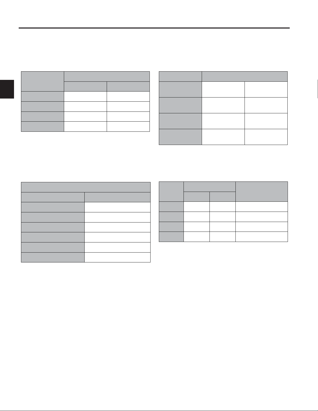
Domestic GrandStand Specications
Engines:
Output (Max. @ 3600 RPM’s)
18 hp
(13.4kW)
Make Kawasaki Kawasaki Kawasaki Kawasaki Kawasaki Kawasaki
Model FS541V FH580V FS600V FH680V FS691V FS730V
Hi-Idle 3600 ± 100
RPM
Starter Electric Electric Electric Electric Electric Electric
Spark Plug NGK BPR4ES Champion
Oil SAE 10w-30/
SAE10w-40
Oil Capacity 2.1 Qt. (2.0 L) 3.8 Pint (1.8L) 2.1 Qt. (2.0 L) 2.0 Qt. (1.9 L) 2.2 Qt. (2.2 L) 2.2 Qt. (2.2 L)
CARB 79534 / 79536 79558 / 79559 No Yes 79548 / 79549 79551
19 hp
(14.2kW)
3600 ± 100
RPM
RCJ8Y
SAE 10w-30/
SAE10w-40
20 hp
(14.9kW)
3600 ± 100
RPM
NGK BPR4ES NGK BPR4ES NGK BPR4ES NGK BPR4ES
SAE 10w-30/
SAE10w-40
23 hp
(17.2kW)
3600 ± 100
RPM
SAE 10w-30/
SAE10w-40
24 hp
(17.9kW)
3600 ± 100
RPM
SAE 10w-30/
SAE10w-40
26 hp
(19.4kW)
3600 ± 100
RPM
SAE 10w-30/
SAE10w-40
2
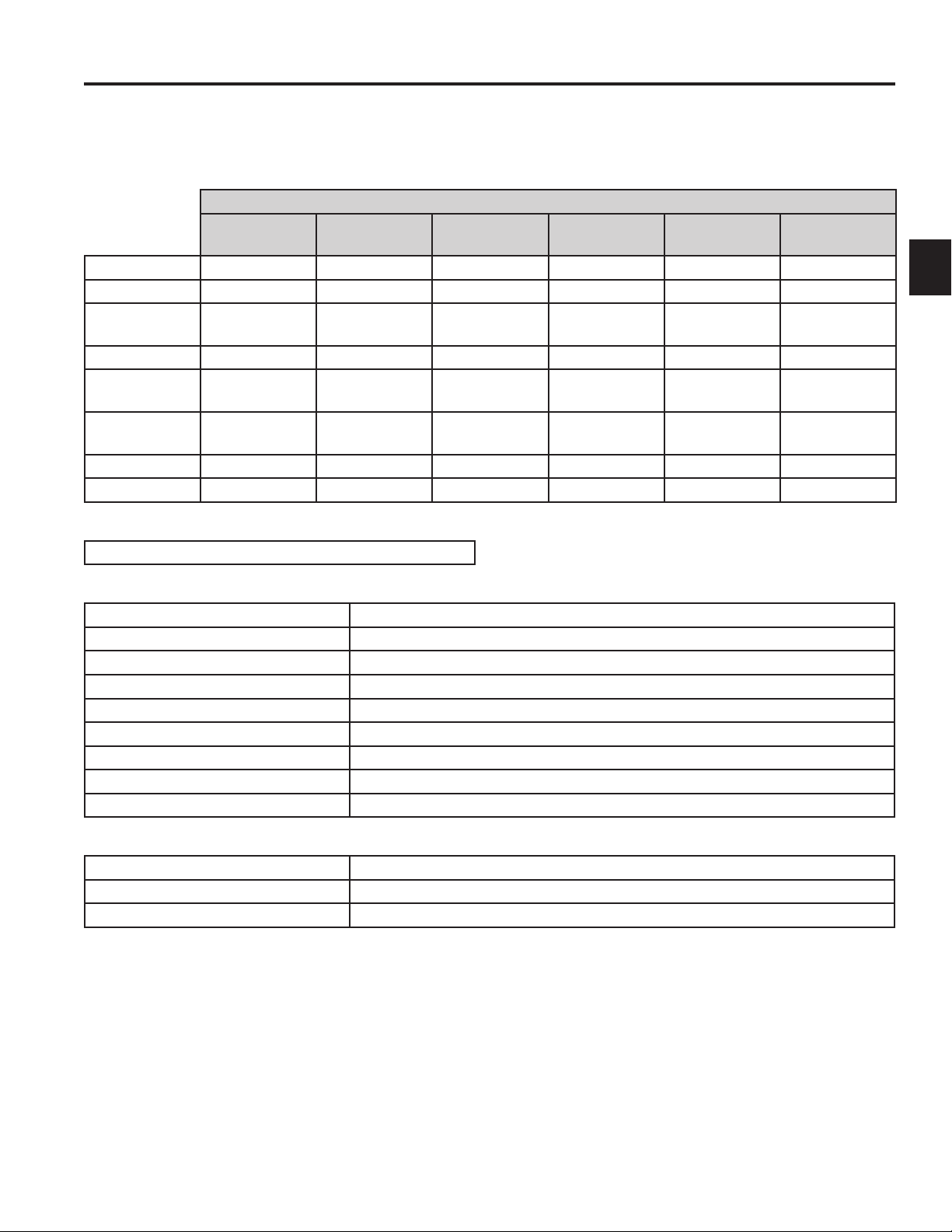
Fuel System:
7 or 12 Gallons (26.5 or 45.4L) fuel tank capacity
Traction Drives:
Traction Control: Toro “Split-Handle” Control Levers
Hydraulic Pump: Two Hydro-Gear Model PG 10cc (Same Part # / No Left & Right)
Hydraulic Wheel Motor: Two Parker TEO-195
Hydraulic Oil Filter: 25 Micron Automotive Spin-On Type
Hydraulic Fluid: Toro Hypr-Oil or Equivalent Synthetic 15w50
Hydraulic Fluid Capacity: 2.1 quarts (1.9 liters)
Parking Brake: Standard Equipment
Ground Speed: (Hydro-MPH) Variable, 3 (5 kph) to 8 (13 kph) MPH Fwd / 0 to 3 (5 kph) MPH Rev
Hourmeter with Service Indicator: Standard Equipment
Wheels & Tires:
Front Castors Tires: 11”x4” - 5”, 4 ply, Smooth Tread, Semi Pneumatic
Front Castors Fork: Heavy-Duty Design with 1” (25.4mm) Diameter Pivot Shaft
Rear Traction Tires: 20”x10”-8”, 4 ply with Turf Traction Tread
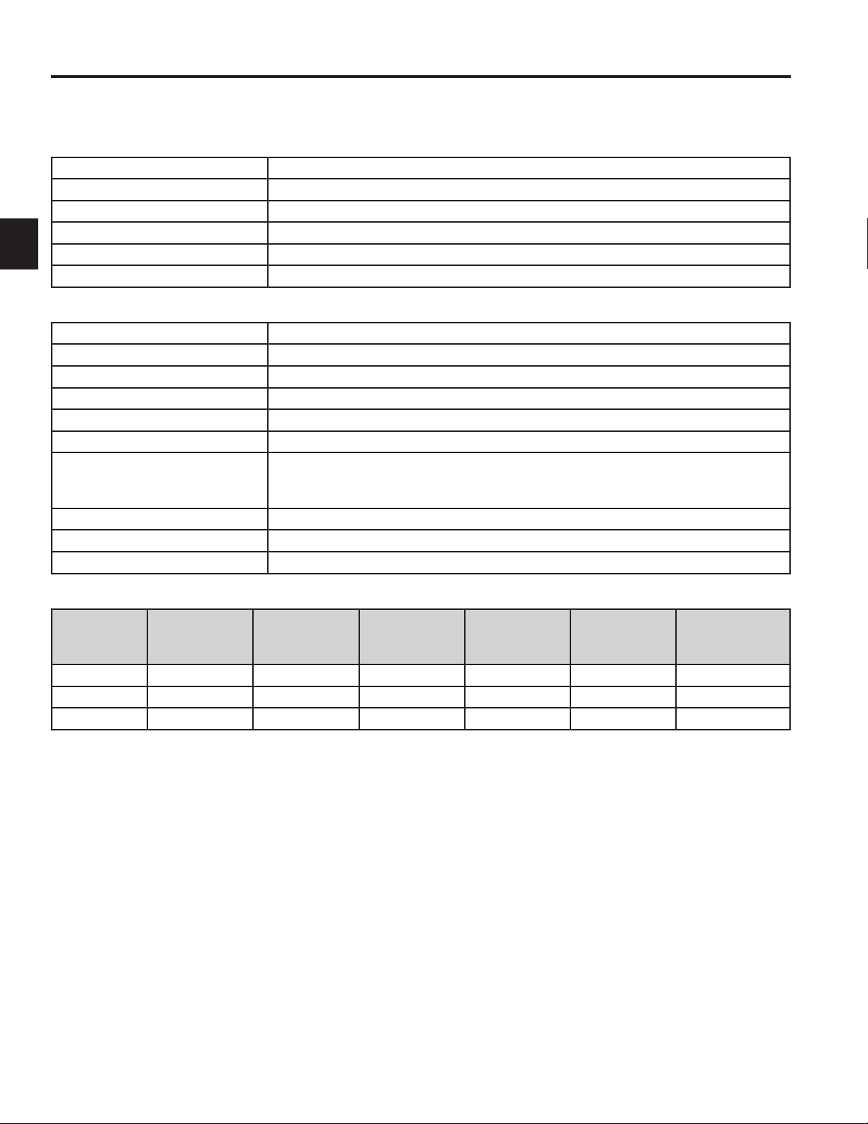
Mower Drive:
2-7Toro GrandStand Service Manual
Page 19
2
SPECIFICATIONS
Domestic GrandStand Specications cont.
Mower Engagement: Engine Mounted Electric Clutch
Clutch Adjustment: Periodic Air Gap Adjustment Required - .018” + .003” (0.45 + 0.0762 mm)
PTO Drive Belt: HB Section w/Aramid (Kevlar) Cords and Dry Clutching Envelope
PTO Idler: Spring Loaded Pivot Hub w/Friction Washer Dampening
Deck Drive Belt: HA Section with Aramid (Kevlar) Cords and Standard (Non-Clutching) Envelope
Deck Drive Idler: Spring Loaded Pivot Hub w/Friction Washer Dampening
Mower Decks:
HOC Range: 1” to 5” in 1/4” increments (25.4mm to 127mm in 6.3mm increments)
Blades: Three .250” (6.3mm) Thick Heat Treated Steel Blades
Spindles: Machined Steel 1.00” (25mm) Diameter Shaft
Spindle Housing: Ductile Cast Iron, 9-3/8” (24cm) Diameter Mounted with Six Bolts
Bearings: Greasable Ball Bearings with Grease Fitting for Lubrication
Construction: 7 gauge (.179” / 4.5mm) Steel Welded Construction
Blade Tip Speed: (Domestic) 48” - 18,750 ft/m calculated @ 3600 engine RPM
52” - 18,750 ft/m calculated @ 3600 engine RPM
60” - 18,750 ft/m calculated @ 3600 engine RPM
Skid Plate: Standard
Adjustable Discharge Bafe: Standard
Rubber Discharge Chute: Standard
Unit Dimensions:
Deck
Width
48” (122cm) 48” (122cm) 63.5” (161cm) 49.5” (126cm) 74” (188cm) 53” (135cm) 887 lbs (400kg)
52” (132cm) 48” (122cm) 67.5” (171cm) 53.5” (135cm) 74” (188cm) 53” (135cm) 900 lbs (408kg)
60” (152cm) 48” (122cm) 75.5” (191cm) 61.5” (156cm) 74” (188cm) 53” (135cm) 925 lbs (419kg)
* Estimated operating weight
Height
Width
Deector
Down
Width
Deector
Raised
Length
Platform
Down
Length
Platform Up
Weight*
2-8 Toro GrandStand Service Manual
Page 20
SPECIFICATIONS
International GrandStand Specications
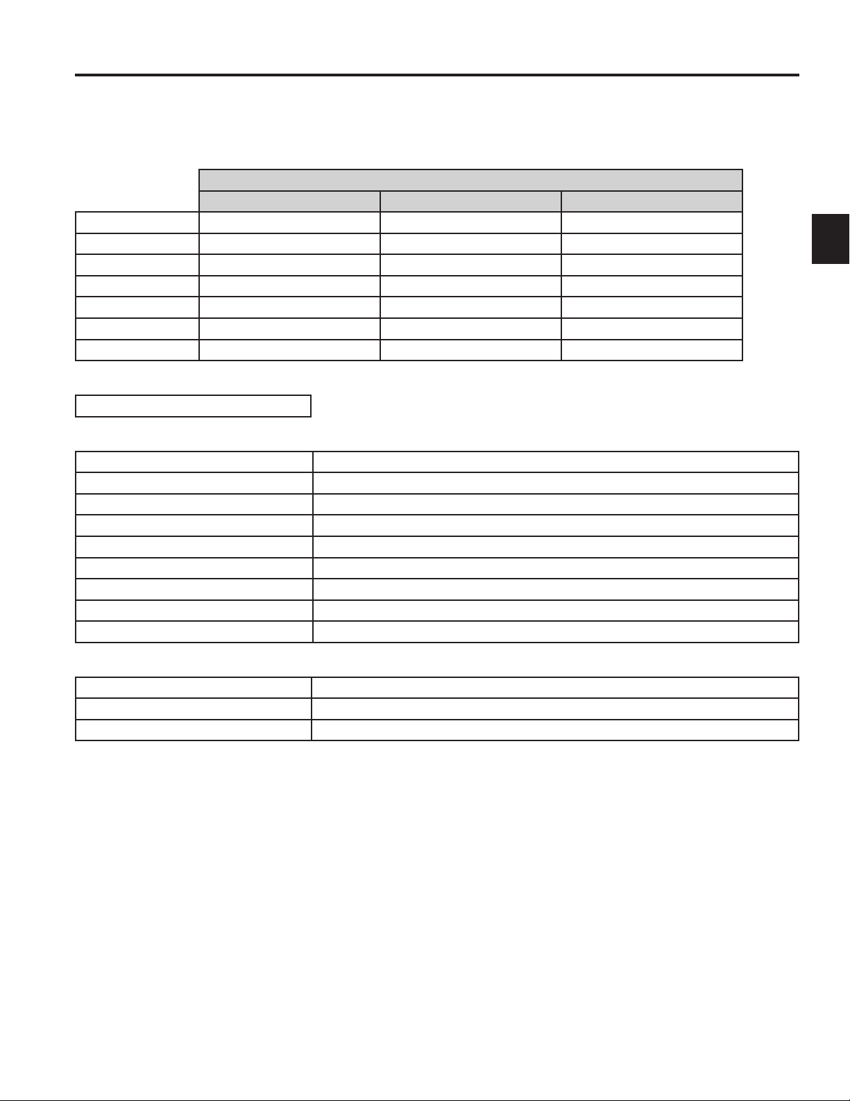
Engines:
Output (Max. @ 3000 RPM’s)
19 hp (14.2 kW) 20 hp (17.2 kW) 23 hp (17.2 kW)
Make Kawasaki Kawasaki Kawasaki
Model FH580V FS600V FH680V
Hi-Idle 2900 ± 100 RPM 2900 ± 100 RPM 2900 ± 100 RPM
Starter Electric Electric Electric
Spark Plug Champion RCJ8Y NGK BPR4ES NGK BPR4ES
Oil SAE 10w-30 / SAE10w-40 SAE 10w-30 / SAE10w-40 SAE 10w-30 / SAE10w-40
Oil Capacity 1.8 L (3.8 pint) 1.9 L (4.0 pint) 1.9 L (4.0 pint)
Fuel System:
26.5 L (7 gal.) Fuel Tank Capacity
Traction Drives:
Traction Control: Toro Twin Lever Control Levers
Hydraulic Pump: Two Hydro-Gear Model PG 10cc (Same Part # / No Left & Right)
Hydraulic Wheel Motor: Two Parker TEO-195
Hydraulic Oil Filter: 25 Micron Automotive Spin-On Type
Hydraulic Fluid: Toro Hypr-Oil or Equivalent Synthetic 15w50
Hydraulic Fluid Capacity: 1.9 L (2.1 quarts)
Parking Brake: Standard Equipment
Ground Speed: Variable, 3 (5 kph) to 8 (13 kph) MPH Fwd / 0 to 3 (5 kph) MPH Rev
Hourmeter with Service Indicator Standard Equipment
2
Wheels and Tires:
Front Castors Tires: 11”x4” - 5”, 4 ply, Smooth Tread, Semi Pneumatic
Front Castors Fork: Heavy-Duty Design with 25.4mm (1”) Diameter Pivot Shaft
Rear Traction Tires: 20”x10”-8”, 4 ply with Turf Traction Tread
2-9Toro GrandStand Service Manual
Page 21
2
SPECIFICATIONS
International GrandStand Specications cont.
Mower Drive:
Mower Engagement: Engine Mounted Electric Clutch
Clutch Adjustment: Periodic Air Gap Adjustment Required - 0.45 ± 0.0762 mm (.018” ± .003”)
PTO Drive Belt: HB Section W/ Aramid (Kevlar) Cords and Dry Clutching Envelope
PTO Idler: Spring Loaded Pivot Hub w/Friction Washer Dampening
Deck Drive Belt: HA Section with Aramid (Kevlar) Cords and Standard (Non-Clutching)
Envelope
Deck Drive Idler: Spring Loaded Pivot Hub w/Friction Washer Dampening
Mower Decks:
HOC Range: 25.4mm (1”) to 127mm (5”) in 6.3mm (1/4”) increments
Blades: Three 6.3mm (.250”) Thick Heat Treated Steel Blades
Spindles: Machined Steel 25.4mm (1”) Diameter Shaft
Spindle Housing: Ductile Cast Iron, Mounted with Six Bolts
Bearings: Greasable Ball Bearings with Grease Fitting for Lubrication
Construction: 7 gauge (.179” / 4.5mm) Steel Welded Construction
Blade Tip Speed: 122cm (48”) - 18,750 ft/m calculated @ 3600 engine RPM
132cm (52”) - 18,750 ft/m calculated @ 3600 engine RPM
Skid Plate: Standard
Adjustable Discharge Bafe: Standard
Rubber Discharge Chute: Standard
Unit Dimensions:
Width
Deck Width Height
122cm (48”) 122cm (48”) 161cm (63.5”) 126cm (49.5”) 135cm (53”) 188cm (74”) 400 kg (881 lbs)
132cm (52”) 122cm (48”) 171cm (67.5”) 135cm (53”) 135cm (53”) 188cm (74”) 408 kg (900 lbs)
* Estimated operating weight
Deector
Down
Width
Deector
Raised
Length
Platform Up
Length
Platform
Down
Weight*
2-10 Toro GrandStand Service Manual
Page 22

CHASSIS
Parking Brake Assembly Replacement
Parking Brake Assembly Removal
1. Move the parking brake lever to the “OFF” position
(Fig. 0001).
Fig. 0001 IMG-1302a
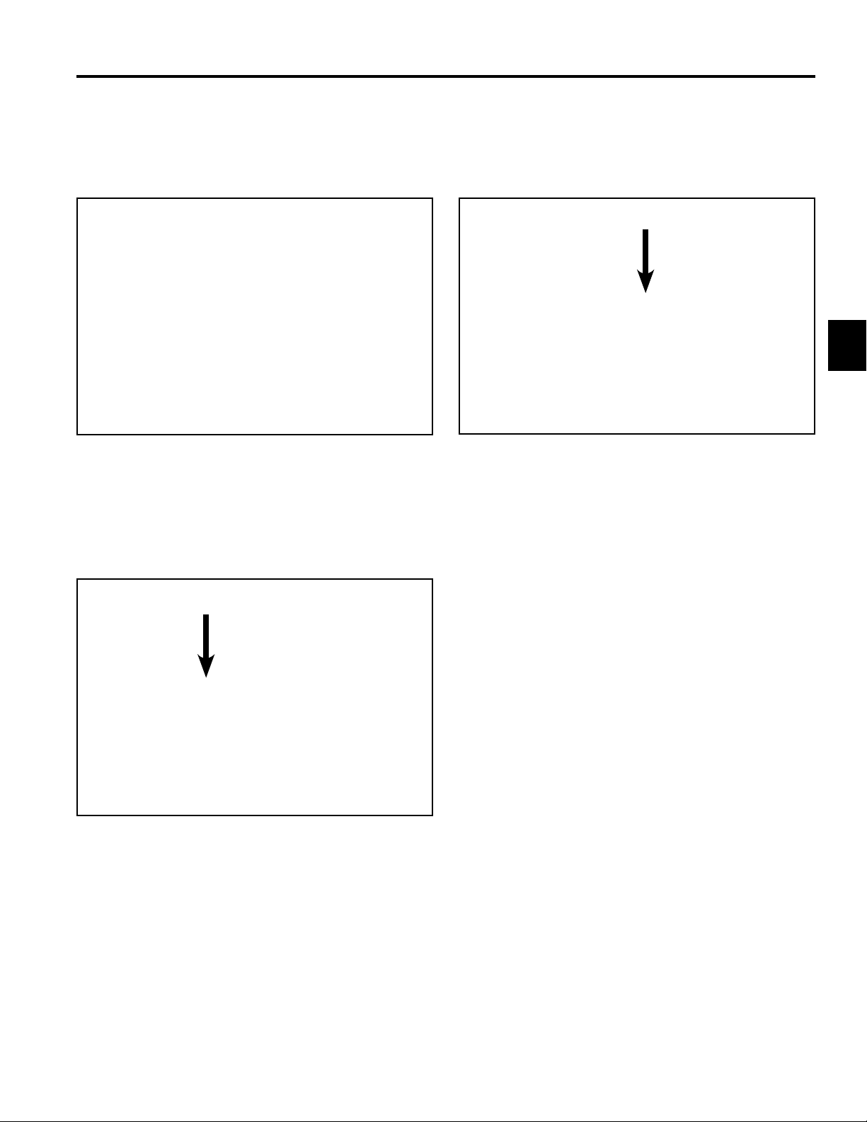
2. Remove the hairpin cotter and clevis pin securing
the linkage yoke at the lower end of the brake rod to
the brake assembly (Fig. 0002).
3
Fig. 0002 DSCN-0264a
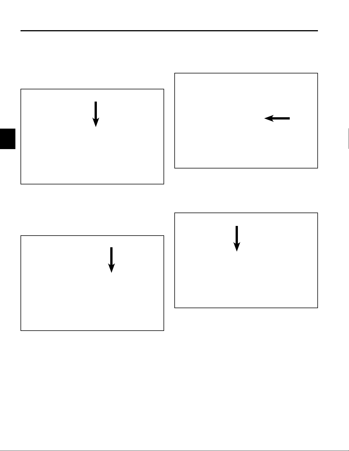
3. Move the parking brake lever to the “ON” position
(Fig. 0003).
Fig. 0003 IMG-1310a
3-1Toro GrandStand Service Manual
Page 23

CHASSIS
3
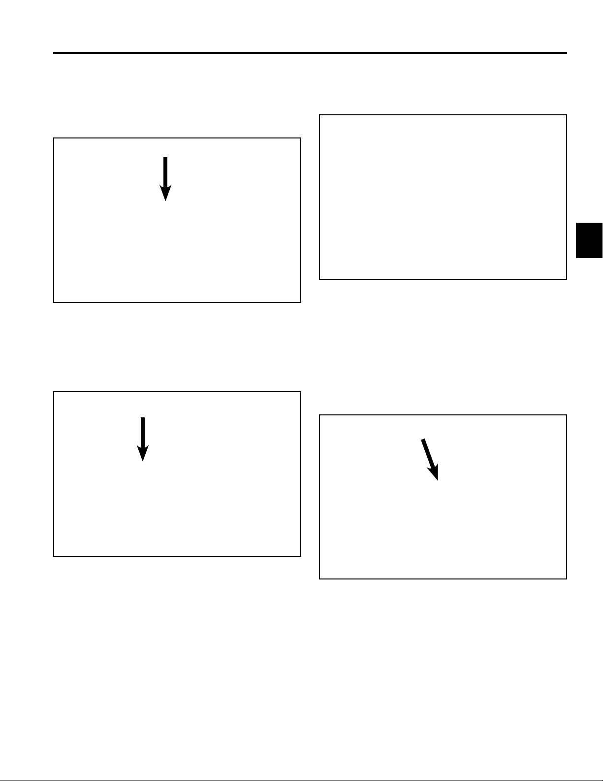
4. Remove the hairpin cotter from the top end of the
parking brake rod. Slide the top end of the rod out of
the handle (Fig. 0004).
Fig. 0004 IMG-9347a
Note: 2010 models use a nut to secure the upper
end of the parking brake rod (Fig. 0005).
5. Remove the hairpin cotter and clevis pin securing
the top and bottom brake arms to the brake lever
(Fig. 0006).
Fig. 0006 DSCN-0268a
6. Disconnect the wire harness from the brake switch
(Fig. 0007).
Fig. 0005 DSCN-0261a
3-2 Toro GrandStand Service Manual
Fig. 0007 DSCN-0265a
Page 24
CHASSIS
7. Remove the carriage bolt and nut securing the brake
lever and brake switch plate to the control tower,
then remove the brake lever and brake switch plate
(Fig. 0008).
Fig. 0008 DSCN-0255a
8. Remove the bolt and nut securing the RH side of the
brake assembly and torsion spring assembly to the
chassis (Fig. 0009).
9. Remove the shoulder bolt, thick washer and nut
securing the LH side of the brake assembly to the
chassis, then remove the brake assembly (Fig.
0010).
3
Fig. 0010 IMG-1325a
Fig. 0009 IMG-1324a
3-3Toro GrandStand Service Manual
Page 25
CHASSIS
3
Parking Brake Assembly Installation
1. Secure the LH side of the brake assembly to the
chassis using the shoulder bolt, thick washer and nut
(Fig. 0011).
Fig. 0011 IMG-1325a
3. Position the bolt and spacer through the chassis
mount and brake assembly. The spacer must be
nested in the chassis mount (Fig. 0013).
Fig. 0013 IMG-1332a
4. Position the large spacer onto the bolt (Fig. 0014).
2. Place the small spacer onto the bolt that secures the
RH side of the brake assembly (Fig. 0012).
Fig. 0012 IMG-1329a
Fig. 0014 IMG-1334a
3-4 Toro GrandStand Service Manual
Page 26
CHASSIS
5. Position the torsion spring over the spacer and
bolt. The straight end of the spring is secured by
the chassis, the curved end hooks under the brake
assembly (Fig. 0015).
Fig. 0015 IMG-1336a
6. Secure the RH assembly using the washer and nut
(Fig. 0016).
7. Position the carriage bolt through the RH side of the
control tower (Fig. 0017).
3
Fig. 0017 IMG-1338a
8. Position the switch plate onto the carriage bolt (Fig.
0018).
Note: The switch plate has a square hole that
must be nested onto the square shank of the
carriage bolt.
Fig. 0016 IMG-1324a
Fig. 0018 IMG-1344a
3-5Toro GrandStand Service Manual
Page 27
CHASSIS
3
9. Position one of the large washers onto the carriage
bolt (Fig. 0019).
Fig. 0019 IMG-1348a
10. Position the shouldered spacer onto the carriage bolt
(Fig. 0020).
11. Position the brake lever through the control panel
and onto the shouldered spacer (Fig. 0021).
Fig. 0021 IMG-1355a
12. Secure the brake lever assembly with the large
washer and nut (Fig. 0022).
Fig. 0020 IMG-1351a
3-6 Toro GrandStand Service Manual
Fig. 0022 DSCN-0255a
Page 28
CHASSIS
13. Position the clevis pin through the bottom brake arm
(Fig. 0023).
Fig. 0023 IMG-1365a
14. Insert the clevis pin through the brake lever (Fig.
0024).
15. Position the top brake arm onto the clevis pin (Fig.
0025).
3
Fig. 0025 DSCN-0259a
16. Install the hairpin cotter to the clevis pin (Fig. 0026).
Fig. 0024 IMG-1367a
Fig. 0026 DSCN-0268a
3-7Toro GrandStand Service Manual
Page 29
CHASSIS
3
17. Plug the wire harness into the brake switch (Fig.
0027).
Fig. 0027 DSCN-0265a
18. Feed the brake rod up through the fuel tank base
and secure the upper end to the brake arm using a
hairpin cotter (Fig. 0028).
Fig. 0028 IMG-9347a
Note: 2010 models use a nut to secure the upper
end of the parking brake rod (Fig. 0029).
Fig. 0029 DSCN-0261a
3-8 Toro GrandStand Service Manual
Page 30
CHASSIS
19. Secure the yoke on the lower end of the brake rod
to the brake assembly using a clevis pin and hairpin
cotter (Fig. 0030).
Fig. 0030 DSCN-0264a
20. The brake assembly should contact the tires when
there is approximately 3/4” (1.9cm) gap between
the front edge of the control panel slot and the front
edge of the brake lever (Fig. 0031).
21. If adjustment is needed, remove the clevis pin securing the yoke to the brake arm. Rotate the yoke to
obtain the desired gap (Fig. 0032).
3
Fig. 0032 DSCN-0264a
A
Fig. 0031 DSCN-0263a
A. 3/4” (1.9cm)
3-9Toro GrandStand Service Manual
Page 31

CHASSIS
3
Height of Cut (HOC) Handle Assembly Replacement
HOC Handle Assembly Removal
1. Lower the deck onto two boards to support the
weight of the deck assembly (Fig. 0033).
Fig. 0033 IMG-1373a
3. 2010 only: Remove the dampener assembly from
the base of the lift bar (Fig. 0035).
Fig. 0035 DSCN-0272a
4. Remove the shoulder bolt, washer and spring
securing the height of cut (HOC) lever to the HOC
handle assembly (Fig. 0036).
2. 2009 only: Remove the nut at the base of the lift
bar (Fig. 0034).
Fig. 0034 DSCN-0274a
Fig. 0036 DSCN-0280a
3-10 Toro GrandStand Service Manual
Page 32

CHASSIS
5. Remove the HOC lever through the slot in the
control panel (Fig. 0037).
Fig. 0037 DSCN-0283a
6. Remove the “E” clip that secures the pivot hub in the
HOC handle assembly (Fig. 0038).
7. Remove the two sets of bolts, nuts and spacers
securing the HOC bracket to the side of the control
tower (Fig. 0039).
3
Fig. 0039 DSCN-0284a
8. Remove the carriage bolt and nut securing the HOC
handle assembly to the control tower (Fig. 0040).
Fig. 0038 DSCN-0285a
Fig. 0040 DSCN-0288a
3-11Toro GrandStand Service Manual
Page 33

CHASSIS
3
9. Move the HOC handle assembly from its frame
mount; then remove the lift bar pivot hub (Fig. 0041).
Fig. 0041 DSCN-0292a
10. Remove the lift bar by lowering it down through the
fuel tank base.
HOC Handle Assembly Installation
1. Install the plastic bushing into the upper end of the
lift bar (Fig. 0043).
Fig. 0043 DSCN-0297a
11. Remove the HOC handle assembly from the control
tower.
12. Remove the plastic bushing from the upper end of
the lift bar (Fig. 0042).
Fig. 0042 DSCN-0297a
3-12 Toro GrandStand Service Manual
Page 34

CHASSIS
2. Position the lift bar up through the slot in the fuel
tank base, to the approximate mounting location Fig.
0044).
Fig. 0044 DSCN-0307a
Note: 2010 only: The tube welded to the base of the
lift bar must face to the right (Fig. 0045).
3. Install the lift arm pivot hub into the HOC handle
assembly (Fig. 0046).
Note: Do not install the “E” clip. It will be installed
in a later step.
3
Fig. 0046 DSCN-0303a
4. Position the HOC handle assembly in the control
tower, just above its mounting bracket. Install the lift
bar onto the pivot hub (Fig. 0047).
Fig. 0045 DSCN-0304a
Fig. 0047 DSCN-0291a
3-13Toro GrandStand Service Manual
Page 35

CHASSIS
3
5. Secure the pivot hub with the “E” clip (Fig. 0048).
Fig. 0048 DSCN-0285a
6. Secure the HOC handle assembly to the control
tower using the carriage bolt and nut (Fig. 0049).
Note: Do not over-tighten. The HOC handle assem-
bly must move freely.
7. Place the two HOC bracket bolts through the side
of the control panel. The carriage bolt goes into the
upper hole (Fig. 0050).
Fig. 0050 DSCN-0323a
8. Place a spacer over each of the bolts (Fig. 0051).
Fig. 0051 DSCN-0325a
Fig. 0049 DSCN-0288a
3-14 Toro GrandStand Service Manual
Page 36

CHASSIS
9. Place the HOC bracket onto the two bolts and
secure with nuts (Fig. 0052).
Fig. 0052 DSCN-0330a
10. Position the HOC lever in through the control panel,
then onto the HOC handle assembly (Fig. 0053).
11. Place the washer, then the spring onto the HOC
lever shoulder bolt (Fig. 0054).
3
Fig. 0054 DSCN-0335a
12. Secure the HOC lever with the shoulder bolt
assembly (Fig. 0055).
Fig. 0053 DSCN-0333a
Fig. 0055 DSCN-0340a
3-15Toro GrandStand Service Manual
Page 37

CHASSIS
3
13. 2009 only: Secure the lower end of the lift bar to
the rear cross shaft assembly using a nut. Thread
the nut onto the bolt until there are 3 threads
protruding (Fig. 0056).
Fig. 0056 DSCN-0274a
14. 2010 only: Secure the lower end of the lift bar to
the rear cross shaft assembly using the dampener
assembly and nut. Thread the dampener assembly
bolt into the nut until there are 3 threads protruding
(Fig. 0057).
15. Remove the boards supporting the deck (Fig. 0058).
Fig. 0058 IMG-1373a
16. Place the HOC pin into the 3” (7.62cm) HOC
position, then verify that the blade tips are also at
3” (7.62cm).
Note: Use the dampener assembly bolt (2009 uses a
nut) to adjust as needed (Fig. 0059).
Fig. 0059 DSCN-0272a
Fig. 0057 DSCN-0793a
3-16 Toro GrandStand Service Manual
Page 38

CHASSIS
Caster Wheel Assembly Replacement
Caster Wheel Assembly Removal
1. Remove the grease cap from the top of the caster
wheel pivot tube (Fig. 0060).
Fig. 0060 DSCN-0357a
3. Remove the caster fork and wheel assembly.
4. Remove the three Bellville washers from the caster
wheel pivot tube (Fig. 0062).
3
Fig. 0062 DSCN-0362a
5. Remove the upper tapered roller bearing from the
caster wheel pivot tube (Fig. 0063).
2. Remove the nut from the caster fork shaft (Fig.
0061).
Fig. 0061 DSCN-0359a
Fig. 0063 DSCN-0364a
3-17Toro GrandStand Service Manual
Page 39

CHASSIS
3
6. Remove the grease seal from the bottom of the
caster wheel pivot tube (Fig. 0064).
Fig. 0064 DSCN-0370a
7. Remove the lower tapered roller bearing (Fig. 0065).
8. If replacing the wheel bearings, use a blunt punch to
remove the upper and lower bearing cups from the
caster wheel pivot tube (Fig. 0066).
Fig. 0066 DSCN-0392a
9. Remove the nut securing the caster wheel axle bolt,
then remove the axle bolt (Fig. 0067).
Fig. 0065 DSCN-0416a
Fig. 0067 DSCN-0376a
3-18 Toro GrandStand Service Manual
Page 40

CHASSIS
10. Remove the caster wheel assembly from the caster
fork.
11. Remove the seal guard from both sides of the wheel
hub (Fig. 0068).
Fig. 0068 DSCN-0377a
12. Remove the spacer nut from the caster axle (Fig.
0069).
3
Fig. 0069 DSCN-0379a
Note: The spacer nuts are both threaded onto the
caster axle. One of the spacer nuts will need
to be removed after it has been removed from
the caster wheel (Fig. 0070).
Fig. 0070 DSCN-0383a
3-19Toro GrandStand Service Manual
Page 41

CHASSIS
3
13. Remove the grease seal from both sides of the
caster wheel (Fig. 0071).
Fig. 0071 DSCN-0387a
14. Remove the LH and RH tapered bearings (Fig.
0072).
Caster Wheel Assembly Installation
1. Pack the caster wheel tapered roller bearing with
high temperature grease (Fig. 0073).
Fig. 0073 DSCN-0407a
2. Install the bearing into the wheel hub (Fig. 0074).
Fig. 0072 DSCN-0389a
Fig. 0074 DSCN-0389a
3-20 Toro GrandStand Service Manual
Page 42

CHASSIS
3. Install grease seal into the wheel hub (Fig. 0075). 6. Position the caster axle through the bearing and seal
assembly (Fig. 0077).
Fig. 0075 DSCN-0393a
Fig. 0077 DSCN-0398a
3
4. Repeat steps 1, 2, and 3 on the other side of the
caster wheel.
5. Fill the center of the wheel hub with high tempera-
ture grease (Fig. 0076).
Fig. 0076 DSCN-0406a
7. Install a spacer nut onto both ends of the caster axle
(Fig. 0078).
Note: There should be approximately 3 internal
spacer nut threads visible on both sides,
indicating the axle is centered.
Fig. 0078 DSCN-0379a
3-21Toro GrandStand Service Manual
Page 43

CHASSIS
3
8. Position the seal guard onto both sides of the caster
wheel hub (Fig. 0079).
Fig. 0079 DSCN-0377a
9. Secure the caster wheel assembly to the caster fork
using the axle bolt and nut (Fig. 0080).
10. Install the upper and lower bearing cups into the
pivot tube (Fig. 0081).
Fig. 0081 DSCN-0410a
Note: A socket can be used as a driver. Take care
not to scar the race surface (Fig. 0082).
Fig. 0080 DSCN-0376a
3-22 Toro GrandStand Service Manual
Fig. 0082 DSCN-0413a
Page 44

CHASSIS
11. Pack the pivot tube tapered roller bearings with high
temperature grease (Fig. 0083).
Fig. 0083 DSCN-0407a
12. Install the lower bearing into the pivot tube (Fig.
0084).
13. Install grease seal into the base of the pivot tube
(Fig. 0085).
3
Fig. 0085 DSCN-0414a
14. Install the upper bearing into the pivot tube (Fig.
0086).
Fig. 0084 DSCN-0416a
Fig. 0086 DSCN-0418a
3-23Toro GrandStand Service Manual
Page 45

CHASSIS
3
15. Install the 3 Bellville washers into the pivot tube (Fig.
0087).
Fig. 0087 DSCN-0428a
Note: Bottom: Crown Up / Middle: Crown Down /
Top: Crown up (Fig. 0088).
16. Insert the caster wheel and fork assembly through
the pivot hub (Fig. 0089).
Fig. 0089 DSCN-0431a
17. Secure the caster wheel and fork assembly with the
nut (Fig. 0090).
Fig. 0088 DSCN-0423a
3-24 Toro GrandStand Service Manual
Fig. 0090 DSCN-0360a
Page 46

CHASSIS
18. Tighten locknut until spring washers are at (15 ftlbs./20 Nm) and then back off a 1/4 turn to properly
set the pre-load on the bearings.
19. Remove the plug from the side of the pivot hub (Fig.
0091).
Fig. 0091 DSCN-0436a
21. Fill the pivot hub cavity until grease is purging out
through the upper bearing (Fig. 0093).
3
Fig. 0093 DSCN-0438a
22. Replace the grease zerk with the plug (Fig. 0094).
20. Install a grease zerk into the port on the side of the
pivot hub (Fig. 0092).
Fig. 0092 DSCN-0434a
Fig. 0094 DSCN-0436a
3-25Toro GrandStand Service Manual
Page 47

CHASSIS
3
23. Install the grease cap onto the top of the pivot hub
(Fig. 0095).
Fig. 0095 DSCN-0357a
Fuel Tank Assembly Replacement
Fuel Tank Assembly Removal
1. Turn the fuel shutoff valve to the “OFF” position (Fig.
0096).
Fig. 0096 DSCN-0457a
2. Siphon the fuel from the fuel tank.
Note: The only recommended way to remove the
fuel from the tank is by using a siphon pump.
3. Remove the height of cut (HOC) pin and lower the
deck (Fig. 0097).
Fig. 0097 DSCN-0459a
3-26 Toro GrandStand Service Manual
Page 48

CHASSIS
4. 2009 only: Remove the 90 degree fuel line vent
tting from the fuel tank (Fig. 0098).
Fig. 0098 IMG-9299a
5. 2009 only: Remove the rubber grommet from the
fuel tank (Fig. 0099).
6. 2009 only: Slide the hose clamp back from the fuel
tank tting, then slide the fuel line off the fuel tank
tting (Fig. 0100).
3
Fig. 0100 IMG-9292a
7. 2009 only: Remove the carriage bolt and nut
securing the fuel tank bracket to the frame bracket,
then remove the fuel tank support (Fig. 0101).
Fig. 0099 IMG-9530b
Fig. 0101 IMG-9304b
3-27Toro GrandStand Service Manual
Page 49

CHASSIS
3
8. 2010 only: Remove the vent line from the 90
degree vent tting (Fig. 0102).
Fig. 0102 DSCN-0461a
9. 2010 only: Remove the 90 degree vent tting, then
rubber grommet from the fuel tank (Fig. 0103).
10. 2010 only: Slide the hose clamp off the fuel pick-up
tube tting, then remove the fuel line from the tting
(Fig. 0104).
Fig. 0104 DSCN-0466a
11. 2010 only: Remove the four thread forming screws
securing the tank bracket to the control panel (Fig.
0105).
Fig. 0103 DSCN-0463a
Fig. 0105 DSCN-0467a
3-28 Toro GrandStand Service Manual
Page 50

CHASSIS
12. Remove the fuel tank from the control tower Fig.
0106).
Fig. 0106 IMG-9307a
Fuel Tank Assembly Installation
1. Position the fuel tank into the control tower (Fig.
0107).
3
Fig. 0107 IMG-9307a
2. 2009 only: Secure the fuel tank bracket to the
frame bracket using the carriage bolt and nut (Fig.
0108).
Fig. 0108 IMG-9304b
3-29Toro GrandStand Service Manual
Page 51

CHASSIS
3
3. 2009 only: Position the fuel line onto the pick-up
tube tting and secure with the hose clamp (Fig.
0109).
Fig. 0109 IMG-9292a
4. 2009 only: Install the rubber grommet into the fuel
tank (Fig. 0110).
5. 2009 only: Install the 90 degree fuel line vent tting
into the fuel tank (Fig. 0111).
Fig. 0111 IMG-9299a
6. 2010 only: Secure the tank bracket using four
thread forming screws (Fig. 0112).
Fig. 0112 DSCN-0467a
Fig. 0110 IMG-9530b
3-30 Toro GrandStand Service Manual
Page 52

CHASSIS
7. 2010 only: Slide the fuel line onto the pick-up tube
tting and secure with the hose clamp (Fig. 0113).
Fig. 0113 DSCN-0466a
8. 2010 only: Install the rubber grommet into the fuel
tank (Fig. 0114).
9. 2010 only: Install the 90 degree tting into the
rubber grommet (Fig. 0115).
Note: A thin lm of oil will ease installation of the
tting barb.
3
Fig. 0115 DSCN-0463a
Fig. 0114 DSCN-0469a
10. Install the vent hose onto vent tting (Fig. 0116).
Fig. 0116 DSCN-0461a
3-31Toro GrandStand Service Manual
Page 53

CHASSIS
3
Platform & Cushion Assembly Replacement
Platform & Cushion Assembly Removal
1. Remove both hairpin cotters securing the cushion
pad to the control tower, then lower the operator
cushion onto the operator platform (Fig. 0117).
Fig. 0117 DSCN-0478a
3. Remove the four sets of bolts and washers securing
the upper and lower pad hinges to the cushion pad
(Fig. 0119).
Fig. 0119 DSCN-0488a
4. Remove the two thread forming screws securing the
shield, foot mat bracket, and foot mat to the platform
(Fig. 0120).
2. Remove the carriage bolts, spacers, friction washers, washers and nuts securing the pad hinge to the
pad links (Fig. 0118).
Fig. 0118 DSCN-0577a
Fig. 0120 DSCN-0490a
3-32 Toro GrandStand Service Manual
Page 54

CHASSIS
5. Remove the RH and LH carriage bolts, washers,
spacers, and nuts securing the platform to the carrier
frame (Fig. 0121).
Fig. 0121 DSCN-0493a
6. Remove the carriage bolts, friction washers, spacers
and nuts securing the LH and RH pad links to the
platform (Fig. 0122).
7. Remove the knob from the platform latch pin (Fig.
0123).
3
Fig. 0123 DSCN-0500a
8. Remove the latch pin and spring from the platform
(Fig. 0124).
Fig. 0122 DSCN-0496a
Fig. 0124 DSCN-0501a
3-33Toro GrandStand Service Manual
Page 55

CHASSIS
3
9. Remove the four nuts securing the four rubber
bumpers to the platform (Fig. 0125).
Fig. 0125 DSCN-0505a
Platform & Cushion Assembly Installation
1. Secure the four rubber bumpers to the platform
using four nuts (Fig. 0126).
Fig. 0126 DSCN-0505a
2. Position the spring on the latch pin (Fig. 0127).
Fig. 0127 DSCN-0512a
3-34 Toro GrandStand Service Manual
Page 56

CHASSIS
3. Position the latch pin and spring assembly into the
platform (Fig. 0128).
Fig. 0128 DSCN-0517a
4. Apply thread-locking compound to the threads of the
knob (Fig. 0129).
5. Install the knob onto the latch pin (Fig. 0130).
3
Fig. 0130 DSCN-0498a
6. Position the carriage bolt and spacer into the tab on
the platform (Fig. 0131).
Fig. 0129 DSCN-0521a
Fig. 0131 DSCN-0548a
3-35Toro GrandStand Service Manual
Page 57

CHASSIS
3
7. Position the friction washer, then the pad link over
the spacer (Fig. 0132).
Fig. 0132 DSCN-0549a
8. Secure the assembly with a washer and nut (Fig.
0133).
9. Repeat steps 6, 7, and 8 on the other side.
10. Position the carriage bolt through the brake support
and the carrier frame (Fig. 0134).
Fig. 0134 DSCN-0531a
11. Position a washer over the carriage bolt (Fig. 0135).
Fig. 0133 DSCN-0555a
Fig. 0135 DSCN-0562a
3-36 Toro GrandStand Service Manual
Page 58

CHASSIS
12. Position the platform so the carriage bolt protrudes
through the platform pivot hole (Fig. 0136).
Fig. 0136 DSCN-0557a
13. Position the spacer over the carriage bolt and into
the platform pivot hole (Fig. 0137).
14. Secure the assembly with a washer and nut (Fig.
0138).
3
Fig. 0138 DSCN-0493a
15. Repeat steps 10 through 14 on the other side of the
machine.
Fig. 0137 DSCN-0560a
16. Secure the shield, foot mat bracket, and foot mat to
the platform using two thread forming screws (Fig.
0139).
Fig. 0139 DSCN-0490a
3-37Toro GrandStand Service Manual
Page 59

CHASSIS
3
17. Secure the shield and lower hinge bracket to the
operator cushion using two screws and washers
(Fig. 0140).
Fig. 0140 DSCN-0564a
18. Secure the upper hinge bracket to the operator
cushion using two screws and washers (Fig. 0141).
19. Align the pad link with the lower hinge bracket (Fig.
0142).
Fig. 0142 DSCN-0568a
20. Place a friction washer between the pad link and
lower hinge bracket (Fig. 0143).
Fig. 0143 DSCN-0571a
Fig. 0141 DSCN-0566a
3-38 Toro GrandStand Service Manual
Page 60

CHASSIS
21. Insert a carriage bolt through the pad link assembly
(Fig. 0144).
Fig. 0144 DSCN-0572a
22. Position the spacer over the carriage bolt and into
the friction washer and lower hinge bracket (Fig.
0145).
23. Secure the assembly with a nut and washer (Fig.
0146).
3
Fig. 0146 DSCN-0577a
24. Repeat steps 19 through 23 on the other side of the
machine.
25. Raise the operator cushion assembly into the operating position and secure with the hairpin cotters and
slide bushings (Fig. 0147).
Fig. 0145 DSCN-0576a
Fig. 0147 DSCN-0582a
3-39Toro GrandStand Service Manual
Page 61

CHASSIS
3
Lift Assist Cylinder Replacement (2009 only)
Lift Assist Cylinder Removal (2009 only)
1. Turn the engine off and remove the key from the
ignition.
2. Set the parking brake.
3. Place Height-of-Cut lever in the transport position.
4. Unlatch cover clamp at front end of gas spring cover
(Fig. 0148).
5. Remove the spring cover (Fig. 0149).
Fig. 0149 IMG-9688a
6. Remove the retaining clip from the front end of the
gas spring assembly (Fig. 0150).
Fig. 0148 IMG-9686a
Fig. 0150 IMG-9697a
3-40 Toro GrandStand Service Manual
Page 62

CHASSIS
7. Repeat steps 4 through 6 on the other side if replacing both gas spring assemblies.
8. Loosen the lower lock nut on the lift bar 1/2 turn (Fig.
0151 and Fig. 0152).
Fig. 0151 IMG-9705a
9. Spin the upper nut approximately 1/2” (1.27cm) up
the lift bar (Fig. 0153).
3
Fig. 0153 IMG-9749a
10. Tighten the lower nut on the lift bar until the compression force on the gas spring assembly has been
relieved and the gas spring assembly can easily be
removed from the ball stud (Fig. 0154).
Fig. 0152 IMG-0088a
Fig. 0154 IMG-9709a
3-41Toro GrandStand Service Manual
Page 63

CHASSIS
3
11. Repeat step 10 on the other side if replacing both
gas spring assemblies.
12. Loosen the lower nut on the lift bar approximately 2
turns until the Height-Of-Cut handle can be moved
from the transport position (Fig. 0155).
Fig. 0155 IMG-9749a
14. Remove the retaining clip from the rear end of the
gas spring assembly (Fig. 0157).
Fig. 0157 IMG-9711a
15. Remove the gas spring assembly (Fig. 0158).
13. Lower the Height-Of-Cut handle to the 1” (2.54cm)
height-of-cut setting (Fig. 0156).
Fig. 0156 IMG-9738a
Fig. 0158 IMG-9714a
16. Repeat steps 14 and 15 on the other side if replacing both gas spring assemblies.
3-42 Toro GrandStand Service Manual
Page 64

CHASSIS
Lift Assist Cylinder Installation (2009 only)
1. Ensure both retaining clips are in the position shown
(Fig. 0159) and (Fig. 0160).
Fig. 0159 IMG-9718a
2. Install the large cylinder end of the gas spring assembly onto the rear ball stud by pressing the gas
spring socket onto the ball stud until it is secured by
the spring clip (Fig. 0161).
3
Fig. 0161 IMG-9724a
3. Repeat step 2 on the other side if replacing both gas
spring assemblies.
Fig. 0160 IMG-9720a
4. Raise the mower deck to the transport position (Fig.
0162).
Fig. 0162 IMG-0080a
3-43Toro GrandStand Service Manual
Page 65

CHASSIS
3
5. Tighten the lower nut on the lift bar until the front end
of the gas spring aligns with the ball stud (Fig. 0163
and Fig. 0164).
Fig. 0163 IMG-9749a
6. Snap the front end of the gas spring onto the ball
stud (Fig. 0165).
Fig. 0165 IMG-9735a
7. Slide the spring cover onto the gas spring assembly
(Fig. 0166).
Fig. 0164 IMG-9729a
Fig. 0166 IMG-9688a
3-44 Toro GrandStand Service Manual
Page 66

CHASSIS
8. Secure the spring cover with the cover clamp (Fig.
0167).
Fig. 0167 IMG-9686a
9. Repeat steps 5 thru 8 on the other side if replacing
both gas spring assemblies.
10. Loosen the lower nut on the lift bar assembly approximately 3 turns until the Height-Of-Cut handle
can be taken out of the transport position (Fig.
0168).
11. Lower the Height-of-Cut lever to the 3” (7.62cm)
Height-Of-Cut position (Fig. 0169).
3
Fig. 0169 IMG-9739a
12. Position the center blade in the front-to-back position. Check the blade height at the front of the center
blade. Adjust the lower nut on the lift bar assembly
until the blade height measurement reaches 3”
(7.62cm) (Fig. 0170).
Fig. 0168 IMG-9749a
Fig. 0170 IMG-9746a
3-45Toro GrandStand Service Manual
Page 67

CHASSIS
3
13. Turn the upper nut on the lift bar assembly down to
the height-of-cut pin (Fig. 0171).
Fig. 0171 IMG-9705
14. Tighten the lower nut on the lift bar assembly to
secure the HOC adjustment (Fig. 0172).
Lift Assist Spring Replacement (2010 only)
Lift Assist Spring Removal (2010 only)
1. Move the height of cut (HOC) lever to the transport
position (Fig. 0173).
Fig. 0173 DSCN-0441a
Fig. 0172 IMG-9705
2. Support the deck with a oor jack (Fig. 0174).
Fig. 0174 DSCN-0442a
3-46 Toro GrandStand Service Manual
Page 68

CHASSIS
3. Move the HOC lever to the 1” (2.54cm) position (Fig.
0175).
Fig. 0175 DSCN-0445a
4. Remove the bolt and washer securing the lift assist
spring to the control tower (Fig. 0176).
5. Remove the spring and chain assembly (Fig. 0177).
3
Fig. 0177 DSCN-0451a
Fig. 0176 DSCN-0447a
3-47Toro GrandStand Service Manual
Page 69

CHASSIS
3
Lift Assist Springs Installation (2010 only)
1. Position the chain between the spring hook and pivot
shaft assembly (Fig. 0178).
Fig. 0178 DSCN-0453a
2. Secure the spring and chain assembly to the control
tower using the bolt and washer (Fig. 0179).
3. Install the bolt until the gap between the control
tower mount and spring cap is 1-1/2” (3.8cm) for 60”
decks / 2” (5cm) 48” or 52” decks (Fig. 0180).
A
Fig. 0180 DSCN-1527a
A. 1-1/2” (3.8cm) for 60” decks
2” (5cm) for 48” for 52” decks
4. Move the HOC lever to the transport position, then
remove the oor jack.
Fig. 0179 DSCN-0455a
3-48 Toro GrandStand Service Manual
Page 70

CHASSIS
Wheel Motor Housing Assembly Replacement
Wheel Motor Housing Assembly Removal
1. Apply the parking brake.
2. Break the torque of the four lug nuts securing the tire
assembly to the wheel hub (Fig. 0181).
Note: Only slightly loosen the lug nuts, do not
remove at this time.
3. Break the torque of the wheel motor shaft nut (Fig.
0182).
Note: Only slightly loosen the wheel motor shaft
nut, do not remove at this time.
3
Fig. 0182 DSCN-0608a
Fig. 0181 DSCN-0608a
4. Repeat steps 2 and 3 on the other side of the
machine.
5. Raise the rear of the machine and secure with jack
stands (Fig. 0183).
Note: Position the jack stands under the rear of the
deck.
Fig. 0183 DSCN-0606a
3-49Toro GrandStand Service Manual
Page 71
CHASSIS
3
6. Remove both tires by removing the four lug nuts
securing each tire to it’s hub (Fig. 0184).
Fig. 0184 DSCN-0608a
7. Remove the wheel motor nut from both wheel
motors (Fig. 0185).
8. Remove both wheel hubs by using a puller (Toro P/N
TOR6006) and four lug nuts (Fig. 0186).
Fig. 0186 DSCN-0614a
Note: Install the lug nut with the taper facing out-
ward (Fig. 0187).
Fig. 0185 DSCN-0611a
3-50 Toro GrandStand Service Manual
Fig. 0187 DSCN-0615a
Page 72

CHASSIS
9. Remove the woodruff key from both of the wheel
motor shafts (Fig. 0188).
Fig. 0188 DSCN-0628a
10. Thoroughly clean the area around the hydraulic
ttings to prevent debris from entering the system.
12. Position a drain pan under the wheel motor (Fig.
0190).
3
Fig. 0190 DSCN-0634a
13. Disconnect both hydraulic hoses from the wheel
motor ttings (Fig. 0191).
11. Mark the hoses, corresponding ttings, and motor
ports to ensure the hoses are reconnected in their
original positions (Fig. 0189).
Fig. 0189 DSCN-0631a
Fig. 0191 DSCN-0636a
3-51Toro GrandStand Service Manual
Page 73

CHASSIS
3
14. Remove both sets of hydraulic ttings from the
wheel motor (Fig. 0192).
Fig. 0192 DSCN-0670a
15. Cap the wheel motor ports and hydraulic hoses to
prevent debris from entering the system (Fig. 0193).
16. Remove the four bolts and washers securing the
wheel motor to the wheel motor housing (Fig. 0194).
Fig. 0194 DSCN-0647a
17. Remove the wheel motor from the wheel motor
housing.
Fig. 0193 DSCN-0639a
18. Repeat steps 6 through 17 on the other side of the
machine.
19. Support the motor mount/axle assembly with a oor
jack (Fig. 0195).
Fig. 0195 DSCN-0649a
3-52 Toro GrandStand Service Manual
Page 74

CHASSIS
20. Remove the four sets (2 per side) of fasteners securing the wheel motor housing assembly to the
carrier frame (Fig. 0196).
Fig. 0196 DSCN-0652a
21. Remove the wheel motor housing assembly.
Wheel Motor Housing Assembly Installation
1. Secure the motor mount center section to the motor
mounts using eight carriage bolts and nuts (Fig.
0198).
3
Fig. 0198 DSCN-0658a
22. Remove the eight carriage bolts and nuts securing
the motor mount center section to the RH and LH
motor mounts (Fig. 0197).
Fig. 0197 DSCN-0658a
Note: The wheel motor housing assembly can be
congured for a wide stance (Fig. 0198) or a
narrow stance (Fig. 0199).
Fig. 0199 DSCN-0661a
3-53Toro GrandStand Service Manual
Page 75

CHASSIS
3
2. Position the motor mount/axle assembly under the
carrier frame (Fig. 0200).
Fig. 0200 DSCN-0649a
3. Loosely install the four sets of bolts (2 per side),
spacers, and nuts that secure the motor mount/axle
assembly to the carrier frame (Fig. 0201).
4. Tighten the four sets of fasteners.
5. Position the wheel motor into the wheel motor
housing (Fig. 0202).
Fig. 0202 DSCN-0664a
6. Secure the wheel motor to the wheel motor housing
using four bolts and Belleville washers. Torque the
bolts to 75 ± 8 ft-lbs. (102 ± 10 Nm) (Fig. 0203).
Fig. 0201 DSCN-0652a
Note: Install the Bellville washers with the crown
facing the bolt head.
Fig. 0203 DSCN-0668a
3-54 Toro GrandStand Service Manual
Page 76

CHASSIS
7. Replace the tting o-rings. Install the two motor
ttings so they point towards the machine. Secure
the position of the ttings with the tting jam nut (Fig.
0204).
Fig. 0204 DSCN-0670a
8. Install the hydraulic hoses to the hydraulic ttings
(Fig. 0205).
9. Repeat steps 5 through 8 on the other side of the
machine.
10. Position the woodruff key in the wheel motor shaft
(Fig. 0206).
3
Fig. 0206 DSCN-0675a
11. Position the wheel hub onto the motor shaft (Fig.
0207).
Fig. 0205 DSCN-0673a
Fig. 0207 DSCN-0676a
3-55Toro GrandStand Service Manual
Page 77

CHASSIS
3
12. Apply thread-locking compound to the wheel motor
shaft threads (Fig. 0208).
Fig. 0208 DSCN-0679a
13. Install the wheel motor nut to the wheel motor shaft
(Fig. 0209).
14. Secure the tire assembly to the wheel hub using four
lug nuts (Fig. 0210).
Note: The lug nuts will have the proper torque
applied in a later step.
Fig. 0210 DSCN-0683a
Note: The wheel motor nut will have the proper
torque applied in a later step.
Fig. 0209 DSCN-0680a
15. Repeat steps 10 through 14 on the other side of the
machine.
16. Remove the jack stands and lower the machine to
the ground.
17. Apply the parking brake.
3-56 Toro GrandStand Service Manual
Page 78

CHASSIS
18. Tighten the wheel motor nut and lug nuts (Fig. 0211).
B
B
B
A
B
Fig. 0211 DSCN-0683a
A. 200 ± 25 ft-lbs. (271 ± 33 Nm)
B. 80 ± 10 ft-lbs. (108 ± 13 Nm)
19. Bleed the hydraulic system. See “Bleeding the
Hydraulic System” on page 6-95.
Cross Shaft & Lift Assembly Replacement
Cross Shaft & Lift Assembly Removal
1. 2009 only: Remove the lift assist cylinder. See “Lift
Assist Cylinder Removal (2009 only)” on page 3-40.
2. Place two boards under the deck and lower the deck
onto them (Fig. 0212).
Note: The boards need to be long enough to sup-
port the front and rear of the deck.
3
Fig. 0212 DSCN-0685a
3. 2009 only: Remove the nut securing the lift bar to
the rear cross shaft assembly (Fig. 0213).
Fig. 0213 DSCN-0795a
3-57Toro GrandStand Service Manual
Page 79

CHASSIS
3
4. 2010 only: Remove the dampener assembly that
secures the lift bar to the rear cross shaft assembly
(Fig. 0214).
Fig. 0214 DSCN-0793a
5. Remove the fuel tank. See “Fuel Tank Assembly
Removal” on page 3-26.
6. Remove the cable ties securing the high pressure
hoses (Fig. 0215).
7. Mark the hydraulic ttings and hoses so they can be
correctly installed upon reassembly (Fig. 0216).
Fig. 0216 DSCN-0691a
8. Remove the high pressure hoses from the pump
ttings (Fig. 0217).
Note: Cap the pump and hose ttings to prevent
debris from entering the hydraulic system.
Fig. 0217 DSCN-0696a
Fig. 0215 DSCN-0689a
3-58 Toro GrandStand Service Manual
Page 80

CHASSIS
9. 2010 only: Remove the bolts and washers securing
the extension spring assemblies and chains to the
RH and LH sides of the control tower (Fig. 0218).
Fig. 0218 DSCN-0700a
10. Remove the “E” clips and washers securing the RH
and LH lift rod to the rear cross shaft assembly (Fig.
0219).
11. 48” and 52” decks only: Remove the nuts from
the end of the lift rods and remove the RH and LH lift
rods (Fig. 0220).
Note: Leave the inside nuts in their location to
minimize deck leveling adjustments at the end
of this procedure.
3
Fig. 0220 DSCN-0707a
Fig. 0219 DSCN-0704a
12. 60” decks only: Loosen the rear jam nuts securing
the LH and RH lift rods to the turn buckle, then remove the RH and LH lift rods (Fig. 0221).
Note: Note the position of the jam nuts to mini mize
deck leveling adjustments at the end of this
procedure.
Fig. 0221 DSCN-0710a
3-59Toro GrandStand Service Manual
Page 81

CHASSIS
3
13. 2009 only: Remove the bolts, spacers, washers
and nuts securing the cross shaft assembly to the
carrier frame (Fig. 0222).
Fig. 0222 DSCN-1602a
14. 2010 only: Using a blunt punch, drive the spiral
pins that secure the LH and RH pivot shafts to the
rear cross shaft assembly (Fig. 0223).
15. 2010 only: Remove the LH and RH pivot shafts
from the rear cross shaft assembly and carrier frame
hub (Fig. 0224).
Note: 48” and 52” decks are set to a narrow stance.
Remove the wheels to remove the pivot
shafts.
Fig. 0224 DSCN-0717a
Fig. 0223 DSCN-0712a
16. Remove the four sets of carriage bolts and nuts (four
per side) securing the LH and RH lift plates to the
engine base (Fig. 0225).
Fig. 0225 DSCN-0720a
3-60 Toro GrandStand Service Manual
Page 82

CHASSIS
17. Remove the lift plates (Fig. 0226).
Fig. 0226 DSCN-0723a
18. Remove the rear cross shaft from the machine (Fig.
0227).
19. Remove the “E” clip securing the height of cut (HOC)
pin to the rear cross shaft assembly (Fig. 0228).
3
Fig. 0228 DSCN-0751a
20. Remove the HOC pin from the rear cross shaft
assembly (Fig. 0229).
Fig. 0227 DSCN-0730a
Fig. 0229 DSCN-0740a
3-61Toro GrandStand Service Manual
Page 83

CHASSIS
3
21. Remove the two 45 degree grease ttings from the
LH and RH grease blocks (Fig. 0230).
Fig. 0230 DSCN-0744a
Cross Shaft & Lift Assembly Installation
1. Install the 45 degree grease tting into the LH and
RH grease blocks. Position the tting so it faces
upward (Fig. 0231).
Fig. 0231 DSCN-0747a
2. Position the HOC pin in the rear cross shaft
assembly (Fig. 0232).
Fig. 0232 DSCN-0740a
3-62 Toro GrandStand Service Manual
Page 84
CHASSIS
3. Secure the position of the HOC pin with the “E” clip
(Fig. 0233).
Fig. 0233 DSCN-0751a
4. Position the rear cross shaft onto the engine base
(Fig. 0234).
3
Fig. 0234 DSCN-0752a
Note: Position the grease blocks so the grease
ttings are pointing upwards (Fig. 0235).
Fig. 0235 DSCN-0756a
3-63Toro GrandStand Service Manual
Page 85
CHASSIS
3
5. Position the right hand lift plate over the grease
block with the bolt hole pattern aligned with the
mating pattern on the engine base (Fig. 0236).
Fig. 0236 DSCN-0758a
6. 2009 only: Loosely install four carriage bolts,
Belleville washers, nuts (Fig. 0237).
7. 2009 only: Tighten the four sets of fasteners.
8. 2010 only: The right side lift plate is secured with
three long carriage bolts and one short (Fig. 0238).
Fig. 0238 DSCN-0768a
9. 2010 only: Loosely install the short carriage bolt
and nut in the upper left bolt hole (Fig. 0239).
Fig. 0237 DSCN-0784a
Fig. 0239 DSCN-0770a
3-64 Toro GrandStand Service Manual
Page 86
CHASSIS
10. 2010 only: Loosely install the remaining three
carriage bolts, Belleville washers, and nuts (Fig.
0240).
Fig. 0240 DSCN-0772a
11. 2010 only: Tighten the four sets of fasteners.
12. Position the left hand lift plate over the grease block
with the bolt hole pattern aligned with the mating
pattern on the engine base (Fig. 0241).
13. Loosely install four carriage bolts, Belleville washers,
nuts (Fig. 0242).
3
Fig. 0242 DSCN-0784a
14. Tighten the four sets of fasteners.
15. 2009 only: Install the spacer into the rear cross
shaft hub (Fig. 0243).
Fig. 0241 DSCN-0780a
Fig. 0243 DSCN-1603a
3-65Toro GrandStand Service Manual
Page 87

CHASSIS
3
16. 2009 only: Install the bolt through the carrier frame,
then through the spacer and hub assembly (Fig.
0244).
Fig. 0244 DSCN-1606a
17. 2009 only: Secure the assembly using a washer
and nut (Fig. 0245).
18. 2009 only: Repeat steps 15, 16 and 17 on the other
side of the unit.
19. 2010 only: Position the RH pivot shaft through the
carrier frame hub and rear cross shaft assembly
(Fig. 0246).
Fig. 0246 DSCN-0717a
Fig. 0245 DSCN-1607a
3-66 Toro GrandStand Service Manual
Page 88

CHASSIS
20. 2010 only: Rotate the pivot shaft so the spiral pin
hole of the pivot shaft aligns with the spiral pin hole
of the rear cross shaft assembly, then secure the
assembly with the spiral pin (Fig. 0247).
Fig. 0247 DSCN-0791a
Note: The spiral pin ends need to be ush to the lift
arm hub (Fig. 0248).
21. 2010 only: Repeat steps 19 and 20 on the LH side
of the machine.
22. 48” and 52” decks: Install the lift rod through the
lift rod bracket and secure with nut (Fig. 0249).
3
Fig. 0249 DSCN-0798a
23. 60” decks: Install the lift rod to the turnbuckle and
secure with jam nut (Fig. 0250).
Fig. 0248 DSCN-1400a
Fig. 0250 DSCN-0797a
3-67Toro GrandStand Service Manual
Page 89

CHASSIS
3
24. Position the opposite end of the lift rod over the stud
on the rear cross shaft assembly (Fig. 0251).
Fig. 0251 DSCN-0801a
Note: Ensure the ange bearing is still in place (Fig.
0252).
25. Position the large washer over the rear cross shaft
stud (Fig. 0253).
Fig. 0253 DSCN-0807a
26. Secure the assembly using the “E” clip (Fig. 0254).
Fig. 0254 DSCN-0808a
Fig. 0252 DSCN-0804a
3-68 Toro GrandStand Service Manual
Page 90

CHASSIS
27. Repeat steps 24 through 26 on the other side of the
machine.
28. Replace the tting o-rings. Install the high pressure
hoses to the pumps in their original positions (Fig.
0255).
Fig. 0255 DSCN-0810a
30. 2009 only: Install the lift assist cylinder. See “Lift
Assist Cylinder Installation (2009 only)” on page
3-43.
31. 2010 only: Position the chain between the pivot
shaft and extension spring assembly (Fig. 0257).
3
Fig. 0257 DSCN-0815a
29. Secure the hose routings using three cable ties (Fig.
0256).
Fig. 0256 DSCN-0689a
32. 2010 only: Secure the extension spring assembly
and chain to the control tower using the bolt and
washer (Fig. 0258).
Fig. 0258 DSCN-0818a
3-69Toro GrandStand Service Manual
Page 91

CHASSIS
3
33. 2010 only: Install the bolt until the gap between the
control tower mount and spring cap is 1-1/2” (3.8cm)
for 60” decks / 2” (5cm) 48” or 52” decks (Fig. 0259).
A
Fig. 0259 DSCN-0820a
A. 1-1/2” (3.8cm) for 60” decks
2” (5cm) for 48” for 52” decks
37. 2010 only: Secure the lower end of the lift bar to
the rear cross shaft assembly using the dampener
assembly and nut. Thread the dampener assembly
bolt into the nut until there are 3 threads protruding
(Fig. 0261).
Fig. 0261 DSCN-0793a
34. 2010 only: Repeat steps 31 through 33 on the other
side of the machine.
35. Install the fuel tank. See “Fuel Tank Assembly Installation” on page 3-29.
36. 2009 only: Secure the lower end of the lift bar to
the rear cross shaft assembly using a nut. Thread
the nut onto the bolt until there are 3 threads protruding (Fig. 0260).
38. Place the HOC pin into the 3” (7.62cm) HOC
position, then verify that the blade height is also at 3”
(7.62cm).
Note: Use the dampener assembly bolt (2009 uses a
nut) to adjust as needed (Fig. 0262).
Fig. 0262 DSCN-0793a
39. Bleed the hydraulic system. See “Bleeding the
Fig. 0260 DSCN-0274a
3-70 Toro GrandStand Service Manual
Hydraulic System” on page 6-95.
Page 92

CHASSIS
Engine Base Replacement
Engine Base Removal
1. 2009 only: Remove the lift assist cylinder. See “Lift
Assist Cylinder Removal (2009 only)” on page 3-40.
2. Place two boards under the deck and lower the deck
onto them (Fig. 0263).
Note: The boards need to be long enough to sup-
port the front and rear of the deck.
4. 2010 only: Remove the dampener assembly that
secures the lift bar to the rear cross shaft assembly
(Fig. 0265).
3
Fig. 0265 DSCN-0793a
5. Remove the fuel tank. See “Fuel Tank Assembly
Removal” on page 3-26.
Fig. 0263 DSCN-0685a
3. 2009 only: Remove the nut securing the lift bar to
the rear cross shaft assembly (Fig. 0264).
6. Remove the cable ties securing the high-pressure
hoses (Fig. 0266).
Fig. 0266 DSCN-0689a
Fig. 0264 DSCN-0795a
3-71Toro GrandStand Service Manual
Page 93

CHASSIS
3
7. Mark the hydraulic ttings and hoses so they can be
correctly installed upon reassembly (Fig. 0267).
Fig. 0267 DSCN-0691a
8. Remove the high-pressure hoses from the pump
ttings (Fig. 0268).
Note: Cap the pump and hose ttings to prevent
debris from entering the hydraulic system.
9. 2010 only: Remove the bolts and washers securing
the exten sion spring assemblies and chains to the
RH and LH sides of the control tower (Fig. 0269).
Fig. 0269 DSCN-0700a
10. Remove the “E” clips and washers securing the RH
and LH lift rod to the rear cross shaft assembly (Fig.
0270).
Fig. 0270 DSCN-0704a
Fig. 0268 DSCN-0696a
3-72 Toro GrandStand Service Manual
Page 94

CHASSIS
11. 48” and 52” decks only: Remove the nuts from
the end of the lift rods and remove the RH and LH lift
rods (Fig. 0271).
Note: Leave the inside nuts in their location to
minimize deck leveling adjustments at the end
of this procedure.
Fig. 0271 DSCN-0707a
13. 2009 only: Remove the bolts, spacers, washers
and nuts securing the cross shaft assembly to the
carrier frame (Fig. 0273).
3
Fig. 0273 DSCN-1602a
14. 2010 only: Using a blunt punch, drive the spiral
pins that secure the LH and RH pivot shafts to the
rear cross shaft assembly (Fig. 0274).
12. 60” decks only: Loosen the rear jam nuts securing
the LH and RH lift rods to the turn buckle, then
remove the RH and LH lift rods (Fig. 0272).
Note: Note the position of the jam nuts to mini mize
deck leveling adjustments at the end of this
procedure.
Fig. 0272 DSCN-0710a
Fig. 0274 DSCN-0712a
3-73Toro GrandStand Service Manual
Page 95

CHASSIS
3
15. 2010 only: Remove the LH and RH pivot shafts
from the rear cross shaft assembly and carrier frame
hub (Fig. 0275).
Note: 48” and 52” decks are set to a narrow stance.
Remove the wheels to remove the pivot
shafts. Reinstall the wheels after removing
the pivot shafts.
Fig. 0275 DSCN-0717a
16. Remove the four carriage bolts and nuts securing
the mufer guard and guard panel to the carrier
frame, then remove both (Fig. 0276).
Fig. 0276 DSCN-0932a
Note: 48” and 52: models use two guard mounting
brackets instead of the single guard panel
(Fig. 0277).
Fig. 0277 IMG-0586a
3-74 Toro GrandStand Service Manual
Page 96

CHASSIS
17. Remove the shoulder bolts, washers, and nuts
securing the LH and RH lift links to the deck (Fig.
0278).
Fig. 0278 DSCN-0935a
18. Loosen the cable clamp securing the choke cable to
the engine throttle plate, then remove the cable from
the clamp (Fig. 0279).
19. Remove the “Z” bend from the engine choke lever
(Fig. 0280).
3
Fig. 0280 DSCN-0945a
20. Loosen the cable clamp securing the throttle cable to
the engine throttle plate, then remove the cable from
the clamp (Fig. 0281).
Fig. 0279 DSCN-0941a
Fig. 0281 DSCN-0946a
3-75Toro GrandStand Service Manual
Page 97

CHASSIS
3
21. Remove the “Z” bend from the engine throttle lever
(Fig. 0282).
Fig. 0282 DSCN-0950a
22. Remove the two sets of wing nuts and hold down
bolts securing the battery cover to the battery tray,
then remove the cover (Fig. 0283).
23. Remove the nut and bolt securing the negative cable
to the battery (Fig. 0284).
Fig. 0284 DSCN-0953a
24. Remove the nut and bolt securing the positive cable
to the battery (Fig. 0285).
Fig. 0285 DSCN-0957a
Fig. 0283 DSCN-0952a
3-76 Toro GrandStand Service Manual
Page 98

CHASSIS
25. Slide the hose clamp back on the fuel line and
remove the fuel line from the fuel lter (Fig. 0286).
Fig. 0286 DSCN-0959a
Note: Position a pan under the fuel hose to catch
any fuel remaining in the fuel hose (Fig. 0287).
26. Slide the hose clamp back on the low-pressure return hose, then remove the hose from the “T” tting
(Fig. 0288).
3
Fig. 0288 DSCN-0965a
27. Slide the hose clamp back on the low-pressure
suction hose, then remove the hose from the “T”
tting (Fig. 0289).
Fig. 0287 DSCN-0962a
Fig. 0289 DSCN-0967a
3-77Toro GrandStand Service Manual
Page 99

CHASSIS
3
28. Disconnect the wire harness from the neutral switch
(Fig. 0290).
Fig. 0290 DSCN-0974a
29. Disconnect the violet wire from the voltage regulator
(Fig. 0291).
30. Unplug the pink wire from the green fuel solenoid
wire (Fig. 0292).
Fig. 0292 DSCN-0978a
31. Unplug the white wire from the black magneto wire
(Fig. 0293).
Fig. 0291 DSCN-0977a
3-78 Toro GrandStand Service Manual
Fig. 0293 DSCN-0980a
Page 100

CHASSIS
32. Remove nut and lock washer securing the positive
battery cable and red wire eyelet to the solenoid post
(Fig. 0294).
Fig. 0294 DSCN-0984a
33. Remove the green and blue bullet connectors from
the two small studs on the solenoid (Fig. 0295).
34. Remove the bolt and washer securing the ground
wires to the engine block (Fig. 0296).
3
Fig. 0296 DSCN-0991a
35. Disconnect the clutch wires from the wiring harness
(Fig. 0297).
Fig. 0295 DSCN-0988a
Fig. 0297 DSCN-0993a
3-79Toro GrandStand Service Manual
 Loading...