

FormNo.3426-484RevB
GrandStand
®
Mower
With91cmor102cmTURBOFORCE
CuttingUnit
ModelNo.74534TE—SerialNo.404330000andUp
ModelNo.74536TE—SerialNo.404330000andUp
®
Registeratwww.T oro.com.
OriginalInstructions(EN)
*3426-484*B
ThisproductcomplieswithallrelevantEuropean
directives;fordetails,pleaseseetheseparateproduct
specicDeclarationofConformity(DOC)sheet.
Pleaserefertotheenginemanufacturer’sinformation
includedwiththemachine.
Introduction
Thisrotary-blade,stand-onlawnmowerisintended
tobeusedbyprofessional,hiredoperators.Itis
designedprimarilyforcuttinggrassonwell-maintained
lawnsonresidentialorcommercialproperties.Using
thisproductforpurposesotherthanitsintendeduse
couldprovedangeroustoyouandbystanders.
Readthisinformationcarefullytolearnhowtooperate
andmaintainyourproductproperlyandtoavoid
injuryandproductdamage.Youareresponsiblefor
operatingtheproductproperlyandsafely.
Visitwww.Toro.comformoreinformation,including
safetytips,trainingmaterials,accessoryinformation,
helpndingadealer,ortoregisteryourproduct.
g272373
Figure1
1.Locationofthemodelandserialnumbers
ModelNo.
SerialNo.
Wheneveryouneedservice,genuineT oroparts,or
additionalinformation,contactanAuthorizedService
DealerorToroCustomerServiceandhavethemodel
andserialnumbersofyourproductready.Figure1
identiesthelocationofthemodelandserialnumbers
ontheproduct.Writethenumbersinthespace
provided.
Important:Withyourmobiledevice,youcan
scantheQRcodeontheserialnumberdecal(if
equipped)toaccesswarranty,parts,andother
productinformation.
Thismanualidentiespotentialhazardsandhas
safetymessagesidentiedbythesafety-alertsymbol
(Figure2),whichsignalsahazardthatmaycause
seriousinjuryordeathifyoudonotfollowthe
recommendedprecautions.
g000502
Figure2
1.Safety-alertsymbol
Thismanualuses2wordstohighlightinformation.
Importantcallsattentiontospecialmechanical
informationandNoteemphasizesgeneralinformation
worthyofspecialattention.
©2019—TheToro®Company
8111LyndaleAvenueSouth
Bloomington,MN55420
Contactusatwww.Toro.com.
2
PrintedintheUSA
AllRightsReserved

Contents
Safety.......................................................................4
GeneralSafety...................................................4
SafetyandInstructionalDecals..........................4
ProductOverview.....................................................9
Controls.............................................................9
Specications..................................................10
Attachments/Accessories.................................10
BeforeOperation..................................................11
BeforeOperationSafety....................................11
AddingFuel.......................................................11
PerformingDailyMaintenance..........................12
BreakinginaNewMachine..............................12
UsingtheSafety-InterlockSystem....................12
DuringOperation.................................................13
DuringOperationSafety...................................13
OperatingtheParkingBrake.............................14
OperatingthePTO............................................15
OperatingtheThrottle.......................................15
OperatingtheChoke........................................15
OperatingtheIgnitionSwitch............................16
StartingtheEngine...........................................16
ShuttingOfftheEngine.....................................17
OperatingthePlatform......................................17
DrivingForwardorBackward............................18
SideDischargingorMulchingthe
Grass............................................................19
AdjustingtheHeightofCut...............................19
AdjustingtheFlowBafe..................................20
PositioningtheFlowBafe................................20
UsingWeights..................................................21
AfterOperation....................................................21
AfterOperationSafety......................................21
UsingtheFuel-ShutoffValve.............................22
PushingtheMachinebyHand..........................22
TransportingtheMachine.................................23
Maintenance...........................................................25
MaintenanceSafety..........................................25
RecommendedMaintenanceSchedule(s)...........26
Pre-MaintenanceProcedures..............................27
RaisingtheMowerforAccess...........................27
ReleasingtheCushionforRearAccess............28
Lubrication..........................................................29
GreasingtheMachine.......................................29
GreasingtheFrontCasterPivots......................29
GreasingtheCaster-WheelHubs.....................30
EngineMaintenance...........................................31
EngineSafety...................................................31
ServicingtheAirCleaner..................................31
ServicingtheEngineOil....................................32
ServicingtheSparkPlug...................................34
CheckingtheSparkArrester.............................35
FuelSystemMaintenance...................................35
DrainingtheFuelT ank......................................35
ReplacingtheFuelFilter...................................36
ElectricalSystemMaintenance...........................37
ElectricalSystemSafety...................................37
ServicingtheBattery.........................................37
ServicingtheFuses..........................................39
DriveSystemMaintenance..................................39
AdjustingtheTracking.....................................39
AdjustingtheProximitySwitch..........................40
CheckingtheTirePressure...............................41
AdjustingtheCaster-PivotBearing...................41
AdjustingtheElectricClutch.............................42
CoolingSystemMaintenance..............................42
CleaningtheAir-IntakeScreen.........................42
CleaningtheCoolingSystem............................42
BrakeMaintenance.............................................43
TestingtheParkingBrake.................................43
CheckingtheBrakeClearance.........................43
AdjustingtheBrakes.........................................44
BeltMaintenance................................................45
CheckingtheBelts............................................45
ReplacingtheMower-DeckBelt........................45
ReplacingthePump-DriveBelt.........................46
ControlsSystemMaintenance.............................47
AdjustingtheRightMotion-Control
Lever.............................................................47
AdjustingtheNeutralPositionforthe
Motion-ControlLevers...................................47
HydraulicSystemMaintenance...........................49
HydraulicSystemSafety...................................49
HydraulicSystemSpecications.......................49
CheckingtheHydraulicFluid............................49
ReplacingtheHydraulicFluid...........................49
ReplacingtheHydraulicFilter...........................50
BleedingtheHydraulicSystem.........................51
CheckingtheHydraulicHoses..........................51
MowerDeckMaintenance....................................52
ServicingtheCuttingBlades.............................52
LevelingtheMowerDeck..................................54
ReplacingtheGrassDeector..........................57
Cleaning..............................................................58
CleaningundertheMowerDeck.......................58
DisposingofWaste...........................................58
Storage...................................................................59
StorageSafety..................................................59
CleaningandStorage.......................................59
Troubleshooting......................................................60
Schematics.............................................................62
3
Safety
Thismachinehasbeendesignedinconsideration
withENISO5395.
GeneralSafety
Thisproductiscapableofamputatinghandsand
feetandofthrowingobjects.Alwaysfollowallsafety
instructionstoavoidseriouspersonalinjury .
•Readandunderstandthecontentsofthis
Operator’sManualbeforestartingtheengine.
•Donotputyourhandsorfeetnearmoving
componentsofthemachine.
•Donotoperatethemachinewithoutallguards
andothersafetyprotectivedevicesinplaceand
functioningproperlyonthemachine.
SafetyandInstructionalDecals
Safetydecalsandinstructionsareeasilyvisibletotheoperatorandarelocatednearanyarea
ofpotentialdanger.Replaceanydecalthatisdamagedormissing.
•Keepclearofthedischargeopening.
•Keepbystandersandchildrenoutoftheoperating
area.Donotallowchildrentooperatethemachine.
Allowonlypeoplewhoareresponsible,trained,
familiarwiththeinstructions,andphysically
capabletooperatethemachine.
•Stopthemachine,shutofftheengine,andremove
theignitionkeybeforeservicing,fueling,or
uncloggingthemachine.
Improperlyusingormaintainingthismachinecan
resultininjury .T oreducethepotentialforinjury,
complywiththesesafetyinstructionsandalways
payattentiontothesafety-alertsymbol
meansCaution,Warning,orDanger—personalsafety
instruction.Failuretocomplywiththeseinstructions
mayresultinpersonalinjuryordeath.
,which
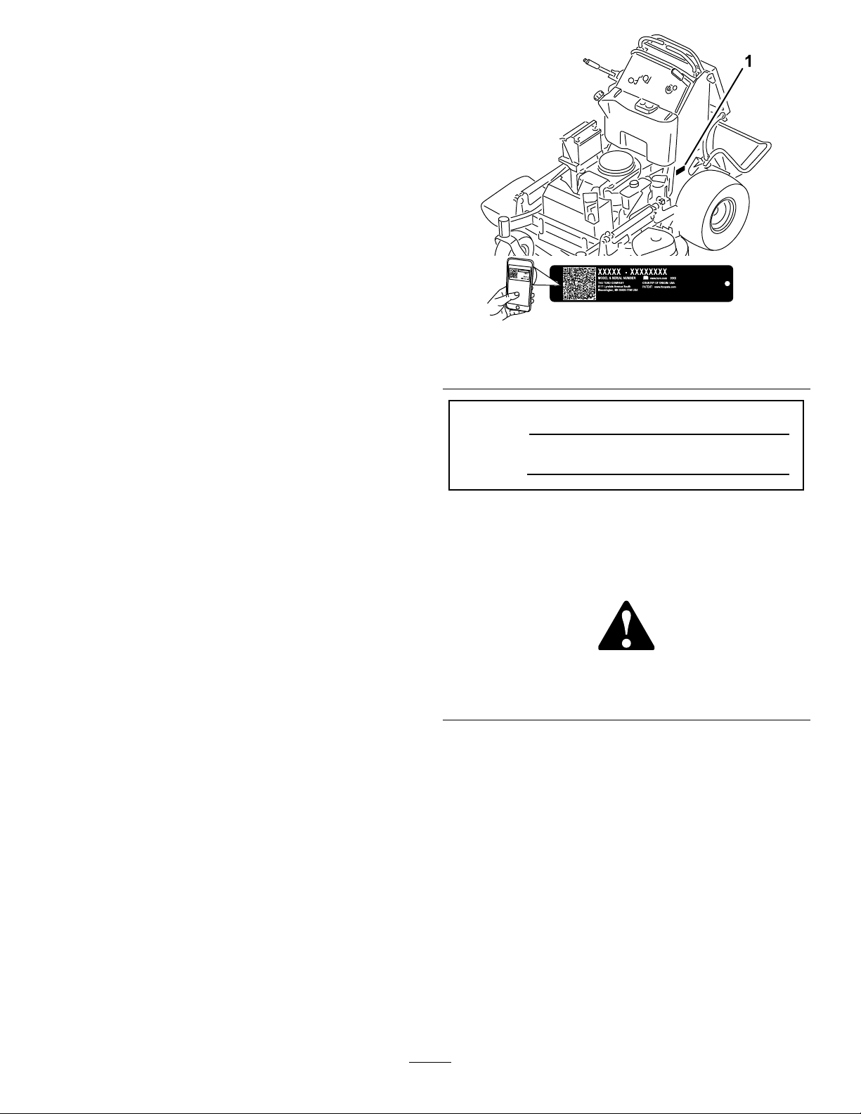
decalbatterysymbols
BatterySymbols
Someorallofthesesymbolsareonyourbattery.
1.Explosionhazard6.Keepbystandersaway.
2.Nore,openames,or
smoking
3.Causticliquid/chemical
burnhazard
4.Weareyeprotection.9.Flusheyesimmediately
5.ReadtheOperator’s
Manual.
7.Weareye
protection—explosive
gasescancauseblindness
andotherinjuries.
8.Batteryacidcancause
severeburns.
withwaterandgetmedical
helpfast.
10.Containslead;donot
discard.
decaloemmarkt
Manufacturer'sMark
1.Indicatesthebladeisidentiedasapartfromtheoriginal
machinemanufacturer.
decal93-7818
93-7818
1.Warning—readtheOperator'sManualforinstructionson
torquingthebladebolt/nutto1 15to149N∙m(85to110
ft-lb).
decal106-5517
106-5517
1.Warning—donottouchthehotsurface.
4
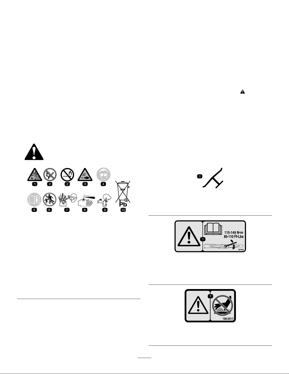
decal110-2067
110-2067
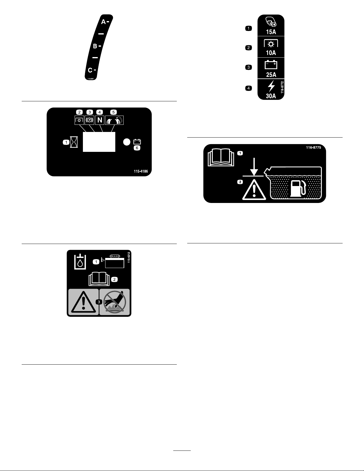
decal116-8772
116-8772
1.Interval
2.PTO
3.Parkingbrake
4.Neutral
5.Operatorpresenceswitch
6.Battery
1.Accessory,15A
2.PTO,10A
decal115-4186
3.Charge,25A
4.Main,30A
115-4186
decal116-8775
116-8775
1.ReadtheOperator’s
Manual.
2.Warning—lltothebottom
ofthellerneck;donot
overllthetank.
1.Hydraulicuidlevel
2.ReadtheOperator's
Manual.
decal115-4212
115-4212
3.Warning—donottouchthe
hotsurface.
5
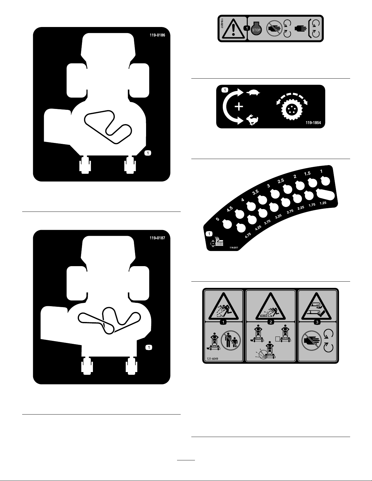
Decal119-0186isfor91cmdecks.
decal119-0217
119-0217
1.Warning—stoptheengine;stayawayfrommovingparts;
keepallguardsandshieldsinplace.
decal119-1854
119-1854
1.Adjustmentknobfortractiondrivespeed.
decal119-0186
119-0186
1.Beltrouting
Decal119-0187isfor102cmdecks.
decal119-2317
119-2317
1.Heightofcut
decal121-6049
121–6049
decal119-0187
119-0187
1.Thrownobject
hazard—keepbystanders
away.
1.Beltrouting
3.Cutting/dismemberment
hazardofhandorfoot,
mowerblade—stayaway
frommovingparts.
2.Thrownobjecthazard,
mower—donotoperate
themowerwithguardsor
shieldsremoved.
6

decal117-0454
117-0454
1.Tractioncontrol
2.Fast4.Neutral
3.Slow
5.Reverse
7.Operatorpresenceswitch
6.PTO—disengage
1.ReadtheOperator'sManualbefore
performinganymaintenance.
2.Checkthedrivewheeltirepressure
every50hours.
119-0241
3.Lubricateevery50hours.
4.Lubricatethecasterwheelevery500
hours.
7
decal119-0241
5.Checkthehydraulicoilevery50hours.
6.Checktheengineoilevery8hours.

125–4679
1.Parkingbrake—disengaged5.Enginespeed
2.Parkingbrake—engaged
6.Slow
3.PTO—engaged7.Continuousvariablesetting
4.PTO—disengaged
8.Fast
139-2878
decal125-4679
decal139-2878
1.Warning—readtheOperator’sManual.
2.Warning—donotoperatethismachineunlessyouaretrained.
6.Thrownobjecthazard—keepbystandersaway.
7.Warning—engagetheparkingbrake,shutofftheengine,and
removethekeybeforeleavingthemachineorperforming
maintenance.
3.Warning—wearhearingprotection.8.Tippinghazard—whenloadingontoatrailer,donotusedual
ramps;onlyuseasingularrampwideenoughforthemachine;
backuptheramp(inreverse)anddriveforwardofftheramp.
4.Thrownobjecthazard—lowerthedeectorbeforeusingthe
machine.
9.Tippinghazard—donotoperatethemachineneardrop-offsor
water;stayasafedistancefromdrop-offs.
5.Cutting/dismembermenthazardofhandorfoot—stayaway
frommovingparts;keepallguardsandshieldsinplace.
8
ProductOverview
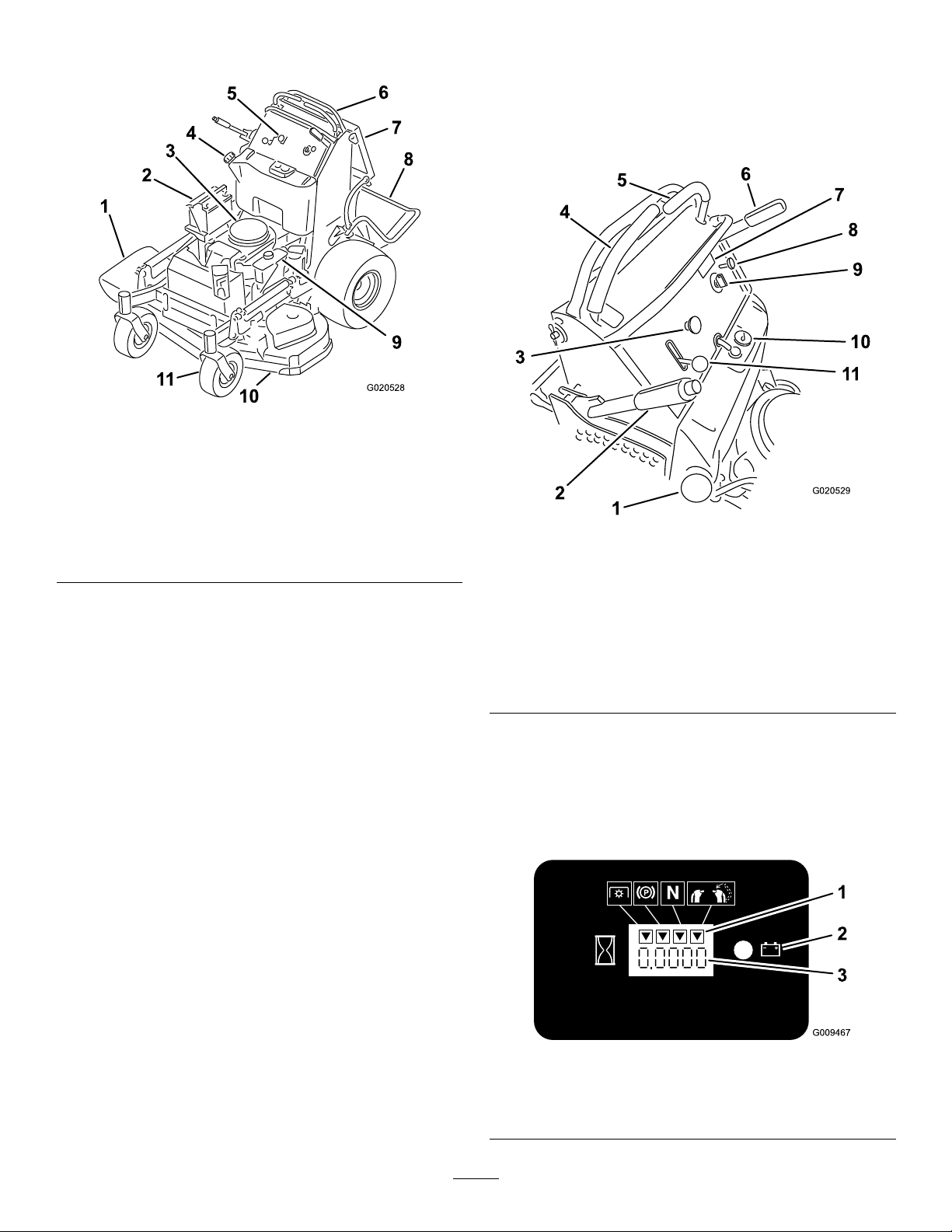
Figure3
1.Side-dischargechute7.Operatorcushion
2.Battery
3.Engine9.Hydraulictank
4.Fueltank10.Mowerdeck
5.Controlpanel
6.Motion-controllevers
8.Platform(downposition)
11.Frontcasterwheel
Controls
Becomefamiliarwithallthecontrolsbeforeyoustart
theengineandoperatethemachine.
ControlPanel
g020528
g020529
Figure4
1.Fuelcap7.Hourmeter
2.Height-of-cutlever8.Chokecontrol
3.Power-Takeoffswitch
(PTO)
4.Rightmotion-controllever10.Fuelgauge
5.Leftmotion-controllever
6.Parking-brakelever
9.Keyswitch
11.Throttlecontrol
HourMeter
Thehourmeterrecordsthenumberofhoursthe
enginehasoperated.Itoperateswhentheengine
isrunning.Usethesetimesforschedulingregular
maintenance(Figure5).
Figure5
1.Safety-interlocksymbols
2.Batterylight
9
3.Hourmeter
g009467

FuelGauge
Specications
Thefuelgaugeislocatedonthetop,middleofthe
tank(Figure4).
Safety-InterlockIndicators
Symbolsonthehourmeterindicatewithablack
trianglethattheinterlockcomponentisinthecorrect
position(Figure5).
Battery-IndicatorLight
IfyouturnthekeytotheONpositionforafew
seconds,thebatteryvoltagedisplaysinthearea
wherethehoursarenormallydisplayed.
Thebatterylightturnsonwhenyouturnthekeytothe
ONpositionandwhenthechargeisbelowthecorrect
operatinglevel(Figure5).
ThrottleControl
Thethrottlecontrolstheenginespeed,andithasa
continuous-variablesettingfromtheSLOWtoFAST
position(Figure4).
Note:Specicationsanddesignaresubjectto
changewithoutnotice.
91cmMowerDeck102cmMower
Cuttingwidth91cm(36inches)102cm(40inches)
Widthwith
deectordown
Lengthwith
platformdown
Lengthwith
platformup
Height
Weight
131cm(52inches)142cm(56inches)
188cm(74inches)178cm(70inches)
155cm(61inches)145cm(57inches)
122cm(48inches)122cm(48inches)
343kg(756lb)351kg(773lb)
Attachments/Accessories
AselectionofT oroapprovedattachmentsand
accessoriesisavailableforusewiththemachine
toenhanceandexpanditscapabilities.Contact
yourAuthorizedServiceDealerorauthorizedT oro
distributororgotowww.Toro.comforalistofall
approvedattachmentsandaccessories.
Deck
ChokeControl
Usethechokecontroltostartacoldengine.Pullthe
chokecontroluptoengageit.Pushdownonthe
chokecontroltodisengageit.
Power-TakeoffSwitch(PTO)
Usethepower-takeoffswitch(PTO)toengageand
disengagethemowerblades(Figure4);referto
OperatingthePTO(page15).
KeySwitch
Thekeyswitch,usedtostartandshutofftheengine,
has3positions:OFF,RUN,andSTART.Referto
OperatingtheIgnitionSwitch(page16).
Motion-ControlLevers
Usethemotion-controlleverstodrivethemachine
forward,reverse,andturneitherdirection(Figure4).
Toensureoptimumperformanceandcontinuedsafety
certicationofthemachine,useonlygenuineT oro
replacementpartsandaccessories.Replacement
partsandaccessoriesmadebyothermanufacturers
couldbedangerous,andsuchusecouldvoidthe
productwarranty.
Fuel-ShutoffValve
Closethefuel-shutoffvalvewhentransportingor
storingthemachine;refertoUsingtheFuel-Shutoff
Valve(page22).
10

Operation
–Storefuelinanapprovedcontainerandkeep
itoutofthereachofchildren.
•Fuelisharmfulorfatalifswallowed.Long-term
BeforeOperation
exposuretovaporscancauseseriousinjuryand
illness.
BeforeOperationSafety
GeneralSafety
•Neverallowchildrenoruntrainedpeopletooperate
themachine.Localregulationsmayrestrictthe
ageoftheoperator.Theownerisresponsiblefor
trainingalloperatorsandmechanics.
•Becomefamiliarwiththesafeoperationofthe
equipment,operatorcontrols,andsafetysigns.
•Knowhowtostopthemachineandshutoffthe
enginequickly.
•Checkthatoperator-presencecontrols,safety
switches,andguardsareattachedandfunctioning
properly.Donotoperatethemachineunlessthey
arefunctioningproperly.
•Beforemowing,alwaysinspectthemachineto
ensurethattheblades,bladebolts,andcutting
assembliesareingoodworkingcondition.
•Inspecttheareawhereyouwillusethemachine
andremoveallobjectsthatthemachinecould
throw.
–Avoidprolongedbreathingofvapors.
–Keepyourhandsandfaceawayfromthe
nozzleandthefuel-tankopening.
–Keepfuelawayfromyoureyesandskin.
•Donotstorethemachineorfuelcontainerwhere
thereisanopename,spark,orpilotlight,such
asonawaterheateroronotherappliances.
•Donotllcontainersinsideavehicleoronatruck
ortrailerbedwithaplasticliner.Alwaysplace
containersontheground,awayfromyourvehicle
beforelling.
•Removetheequipmentfromthetruckortrailer
andrefuelitwhileitisontheground.Ifthisisnot
possible,thenrefuelfromaportablecontainer
ratherthanafuel-dispensernozzle.
•Donotoperatethemachinewithouttheentire
exhaustsysteminplaceandinproperworking
condition.
•Keepthefuel-dispensernozzleincontactwith
therimofthefueltankorcontaineropeningat
alltimesuntilfuelingiscomplete.Donotusea
nozzlelock-opendevice.
•Evaluatetheterraintodeterminetheappropriate
equipmentandanyattachmentsoraccessories
requiredtooperatethemachineproperlyand
safely.
FuelSafety
•Fuelisextremelyammableandhighlyexplosive.
Areorexplosionfromfuelcanburnyouand
othersandcandamageproperty .
–T opreventastaticchargefromignitingthefuel,
placethecontainerand/ormachinedirectlyon
thegroundbeforelling,notinavehicleoron
anobject.
–Fillthefueltankoutdoors,inanopenarea,
whentheengineiscold.Wipeupanyfuelthat
spills.
–Donothandlefuelwhensmokingoraroundan
openameorsparks.
–Donotremovethefuelcaporaddfueltothe
tankwhiletheengineisrunningorhot.
–Ifyouspillfuel,donotattempttostartthe
engine.Avoidcreatingasourceofignitionuntil
thefuelvaporshavedissipated.
•Ifyouspillfuelonyourclothing,changeyour
clothingimmediately.Wipeupanyfuelthatspills.
•Neveroverllthefueltank.Replacethefuelcap
andtightenitsecurely.
AddingFuel
RecommendedFuel
•Forbestresults,useonlyclean,fresh(lessthan
30daysold),unleadedgasolinewithanoctane
ratingof87orhigher((R+M)/2ratingmethod).
•Ethanol:Gasolinewithupto10%ethanol
(gasohol)or15%MTBE(methyltertiarybutyl
ether)byvolumeisacceptable.Ethanoland
MTBEarenotthesame.Gasolinewith15%
ethanol(E15)byvolumeisnotapprovedforuse.
Neverusegasolinethatcontainsmorethan
10%ethanolbyvolume,suchasE15(contains
15%ethanol),E20(contains20%ethanol),orE85
(containsupto85%ethanol).Usingunapproved
gasolinemaycauseperformanceproblemsand/or
enginedamagewhichmaynotbecoveredunder
warranty.
11

•Donotusegasolinecontainingmethanol.
•Donotstorefueleitherinthefueltankorfuel
containersoverthewinterunlessyouuseafuel
stabilizer.
UsingtheSafety-Interlock
System
•Donotaddoiltogasoline.
UsingStabilizer/Conditioner
Usefuelstabilizer/conditionerinthemachinetokeep
thefuelfreshlongerwhenusedasdirectedbythe
fuel-stabilizermanufacturer.
Important:Donotusefueladditivescontaining
methanolorethanol.
Addtheamountoffuelstabilizer/conditionertofresh
fuelasdirectedbythefuel-stabilizermanufacturer.
FillingtheFuelTank
1.Parkthemachineonalevelsurface,disengage
thePTO,movethemotion-controlleverstothe
NEUTRAL-LOCKposition,andengagetheparking
brake.
2.Shutofftheengine,removethekey,andwait
forallmovingpartstostopbeforeleavingthe
operatingposition.
3.Cleanaroundthefuel-tankcapandremovethe
cap.
4.Fillthefueltanktothebottomofthellerneck.
Note:Donotllthefueltankcompletelyfull.
Theemptyspaceinthetankallowsthegasoline
toexpand.
WARNING
Ifsafety-interlockswitchesaredisconnected
ordamaged,themachinecouldoperate
unexpectedly,causingpersonalinjury.
•Donottamperwiththeinterlockswitches.
•Checktheoperationoftheinterlock
switchesdaily ,andreplaceanydamaged
switchesbeforeoperatingthemachine.
Understandingthe
Safety-InterlockSystem
Thesafety-interlocksystemisdesignedtoprevent
PTOfromengagingunlessyoudo1ofthefollowing:
•Movetherightmotion-controllevertothecenter,
unlockedposition.
•PullthePTOswitchtotheONposition.
Thesafety-interlocksystemisdesignedtostop
theblades/attachmentifyoumoveorrelease
bothmotion-controlleversintotheNEUTRAL-LOCK
position.
Thehourmeterhassymbolstonotifytheuser
wheneachinterlockcomponentisinthecorrect
position.Whenthecomponentisinthecorrect
position,atrianglelightsupinthecorresponding
square(Figure6).
5.Installthefuel-tankcapsecurely.Wipeupany
spilledfuel.
PerformingDaily
Maintenance
Beforestartingthemachineeachday,performthe
EachUse/DailyprocedureslistedinMaintenance
(page25).
BreakinginaNewMachine
Newenginestaketimetodevelopfullpower.Mower
decksanddrivesystemshavehigherfrictionwhen
new,placingadditionalloadontheengine.Allow
40to50hoursofbreak-intimefornewmachinesto
developfullpowerandbestperformance.
g009472
Figure6
1.Thetriangleslightupwhentheinterlockcomponentsare
inthecorrectposition.
12

TestingtheSafety-Interlock
DuringOperation
System
ServiceInterval:Beforeeachuseordaily
Testthesafety-interlocksystembeforeyouusethe
machineeachtime.
Note:Ifthesafetysystemdoesnotoperateas
describedbelow,haveanAuthorizedServiceDealer
repairthesafetysystemimmediately.
1.Starttheengine;refertoStartingtheEngine
(page16).
2.Movetherightmotion-controllevertothecenter,
unlockedposition.
Note:Theblades/attachmentshouldstopand
theengineshouldstoprunning.
3.Starttheengineanddisengagetheparking
brake.
4.Movetherightmotion-controllevertothecenter,
unlockedposition.
5.Continueholdingthemotion-controlleverinthe
center,unlockedposition,pulluponthePTO
switch,andreleasetheswitch.
Note:Theclutchandblades/attachmentshould
engage.
6.Moveorreleasetherightmotion-controllever
intotheNEUTRAL-LOCKposition.
Note:Theblades/attachmentshouldstopand
theengineshouldcontinuetorun.
7.PushthePTOswitchdownandmovetheright
motion-controllevertothecenter,unlocked
position.
8.Continueholdingthemotion-controlleverinthe
center,unlockedposition,pulluponthePTO
switch,andreleasetheswitch.
Note:Theclutchandblades/attachmentshould
engage.
9.PushthePTOswitchdowntotheOFFposition.
Note:Theblades/attachmentshouldstop.
10.Withtheenginerunning,pullupthePTO
switchandreleaseitwithoutholdingtheright
motion-controllevertothecenter,unlocked
position.
Note:Theblades/attachmentshouldnot
engage.
DuringOperationSafety
GeneralSafety
•Theowner/operatorcanpreventandisresponsible
foraccidentsthatmaycausepersonalinjuryor
propertydamage.
•Wearappropriateclothing,includingeye
protection;longpants;substantial,slip-resistant
footwear;andhearingprotection.Tiebacklong
hairanddonotwearlooseclothingorloose
jewelry.
•Useyourfullattentionwhileoperatingthe
machine.Donotengageinanyactivitythat
causesdistractions;otherwise,injuryorproperty
damagemayoccur.
•Donotoperatethemachinewhileill,tired,or
undertheinuenceofalcoholordrugs.
•Nevercarrypassengersonthemachineandkeep
bystandersandpetsawayfromthemachine
duringoperation.
•Operatethemachineonlyingoodvisibilityand
appropriateweatherconditions.Donotoperate
themachinewhenthereistheriskoflightning.
•Wetgrassorleavescancauseseriousinjuryif
youslipandcontacttheblade.Avoidmowingin
wetconditions.
•Beforeyoustarttheengine,ensurethatalldrives
areinneutral,theparkingbrakeisengaged,and
youareintheoperatingposition.
•Ensurethatyouhavegoodfootingwhileusingthis
machine,especiallywhenbackingup.
•Keepyourhandsandfeetawayfromthecutting
units.Keepclearofthedischargeopeningatall
times.
•Lookbehindanddownbeforebackinguptobe
sureofaclearpath.
•Useextremecarewhenapproachingblind
corners,shrubs,trees,orotherobjectsthatmay
blockyourview.
•Stopthebladeswheneveryouarenotmowing.
•Stopthemachine,removetheignitionkey ,and
waitforallmovingpartstostopbeforeinspecting
themowerdeckorattachmentafterstrikingan
objectorifthereisanabnormalvibrationinthe
machine.Makeallnecessaryrepairsbefore
resumingoperation.
•Slowdownandusecautionwhenmakingturns
andcrossingroadsandsidewalkswiththe
machine.Alwaysyieldtheright-of-way.
13
•Disengagethecuttingunitandshutofftheengine
beforeadjustingtheheightofcut(unlessyoucan
adjustitfromtheoperatingposition).
•Operatetheengineonlyinwell-ventilatedareas.
Exhaustgasescontaincarbonmonoxide,which
islethalifinhaled.
•Neverleavearunningmachineunattended.
•Beforeleavingtheoperatingposition(including
toemptythecatchersortounclogthechute),do
thefollowing:
–Parkthemachineonalevelsurface.
–Disengagethepowertake-off.
–Engagetheparkingbrake.
–Shutofftheengineandremovetheignitionkey .
–Waitforallmovingpartstostop.
•Shutoffthemachineanddisengagethedriveto
thecuttingunitinthefollowingsituations:
–Beforefueling
–Beforeclearingblockages
–Beforechecking,cleaning,ormaintainingthe
cuttingunit
–Afterstrikingaforeignobjectorifanabnormal
vibrationoccurs.Inspectthecuttingunitfor
damageandmakerepairsbeforestartingand
operatingthemachine
–Beforeleavingtheoperatingposition
•Donotusethemachineasatowingvehicle.
•Useonlyaccessoriesandattachmentsapproved
byTheT oro®Company.
SlopeSafety
•Slopesareamajorfactorrelatedtolossofcontrol
androlloveraccidents,whichcanresultinsevere
injuryordeath.Y ouareresponsibleforsafeslope
operation.Operatingthemachineonanyslope
requiresextracaution.Beforeusingthemachine
onaslope,dothefollowing:
–Reviewandunderstandtheslopeinstructions
inthemanualandonthemachine.
–Evaluatethesiteconditionsofthedayto
determineiftheslopeissafeformachine
operation.Usecommonsenseandgood
judgmentwhenperformingthisevaluation.
Changesintheterrain,suchasmoisture,can
quicklyaffecttheoperationofthemachineon
aslope.
•Operateacrossslopes,neverupanddown.Avoid
operationonexcessivelysteeporwetslopes.
•Identifyhazardsatthebaseoftheslope.Do
notoperatethemachineneardrop-offs,ditches,
embankments,water,orotherhazards.The
machinecouldsuddenlyrolloverifawheelgoes
overtheedgeortheedgecollapses.Keepasafe
distance(twicethewidthofthemachine)between
themachineandanyhazard.Useawalk-behind
machineorahandheldtooltooperateinthese
areas.
•Avoidstarting,stopping,orturningthemachineon
slopes.Avoidmakingsuddenchangesinspeedor
direction;turnslowlyandgradually.
•Donotoperateamachineunderanyconditions
wheretraction,steeringorstabilityisinquestion.
Beawarethatoperatingthemachineonwet
grass,acrossslopesordownhillmaycausethe
machinetolosetraction.Lossoftractiontothe
drivewheelsmayresultinslidingandalossof
brakingandsteering.Themachinecanslideeven
ifthedrivewheelsarestopped.
•Removeormarkobstaclessuchasditches,holes,
ruts,bumps,rocks,orotherhiddenhazards.Tall
grasscanhideobstacles.Uneventerraincould
overturnthemachine.
•Useextracarewhileoperatingwithaccessoriesor
attachments.Thesecanchangethestabilityof
themachineandcausealossofcontrol.Follow
directionsforcounterweights.
•Ifyoulosecontrolofthemachine,stepoffand
awayfromthedirectionoftravelofthemachine.
OperatingtheParking
Brake
Alwaysengagetheparkingbrakewhenyoushutoff
themachineorleaveitunattended.Beforeeachuse,
checktheparkingbrakeforproperoperation.
Iftheparkingbrakedoesnotholdsecurely ,adjustit;
refertoOperatingtheParkingBrake(page14).
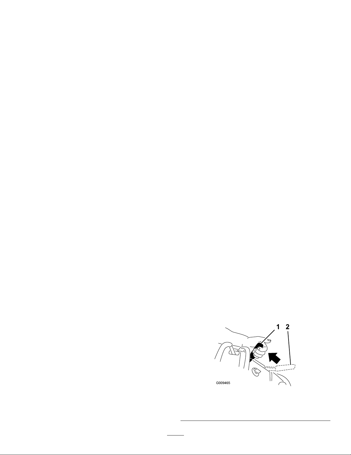
Pulltheparking-brakeleverrearwardtoengageit
(Figure7).
Pushtheparking-brakeleverforwardtodisengageit.
g009465
Figure7
1.Parkingbrake—engaged2.Parking
brake—disengaged
14
OperatingthePTO
OperatingtheThrottle
Usethepower-takeoff(PTO)switchinconjunctionwith
themotion-controlleverstoengageanddisengage
mowerbladesorpoweredattachments.
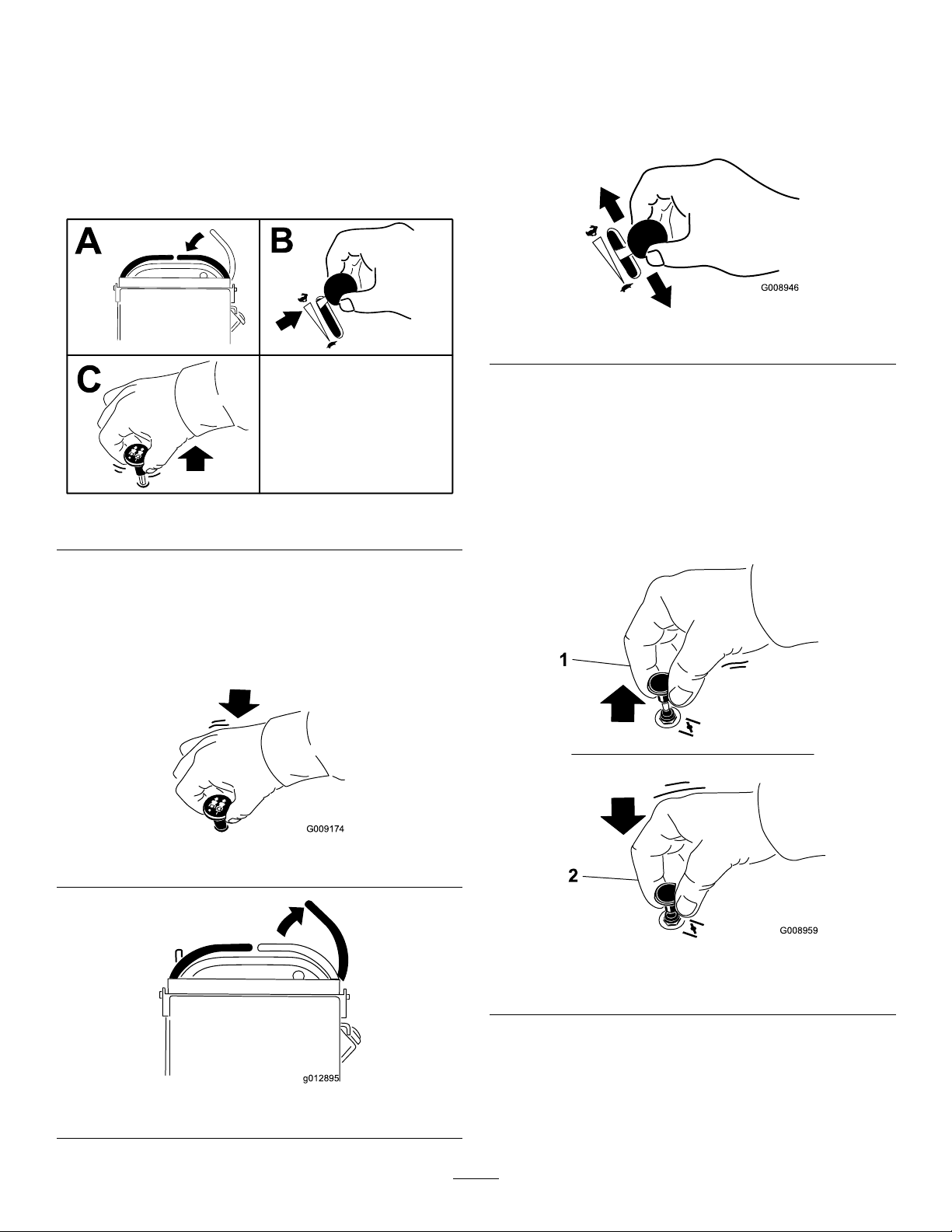
EngagingthePower-Takeoff(PTO)
Switch
Figure8
YoucanmovethethrottlecontrolbetweenFASTand
SLOWpositions(Figure11).
AlwaysusetheFASTpositionwhenengagingthePTO.
g008946
Figure11
OperatingtheChoke
Usethechoketostartacoldengine.
1.Pullupthechokeknobtoengagethechoke
g216326
beforeusingthekeyswitch(Figure12).
2.Pushdownthechokeknobtodisengagethe
chokeaftertheenginehasstarted(Figure12).
DisengagingthePower-Takeoff
(PTO)Switch
Figure9andFigure10show2waystodisengage
thePTO.
Figure9
g009174
g008959
Figure12
1.ONposition2.OFFposition
Figure10
g012895
15
OperatingtheIgnition
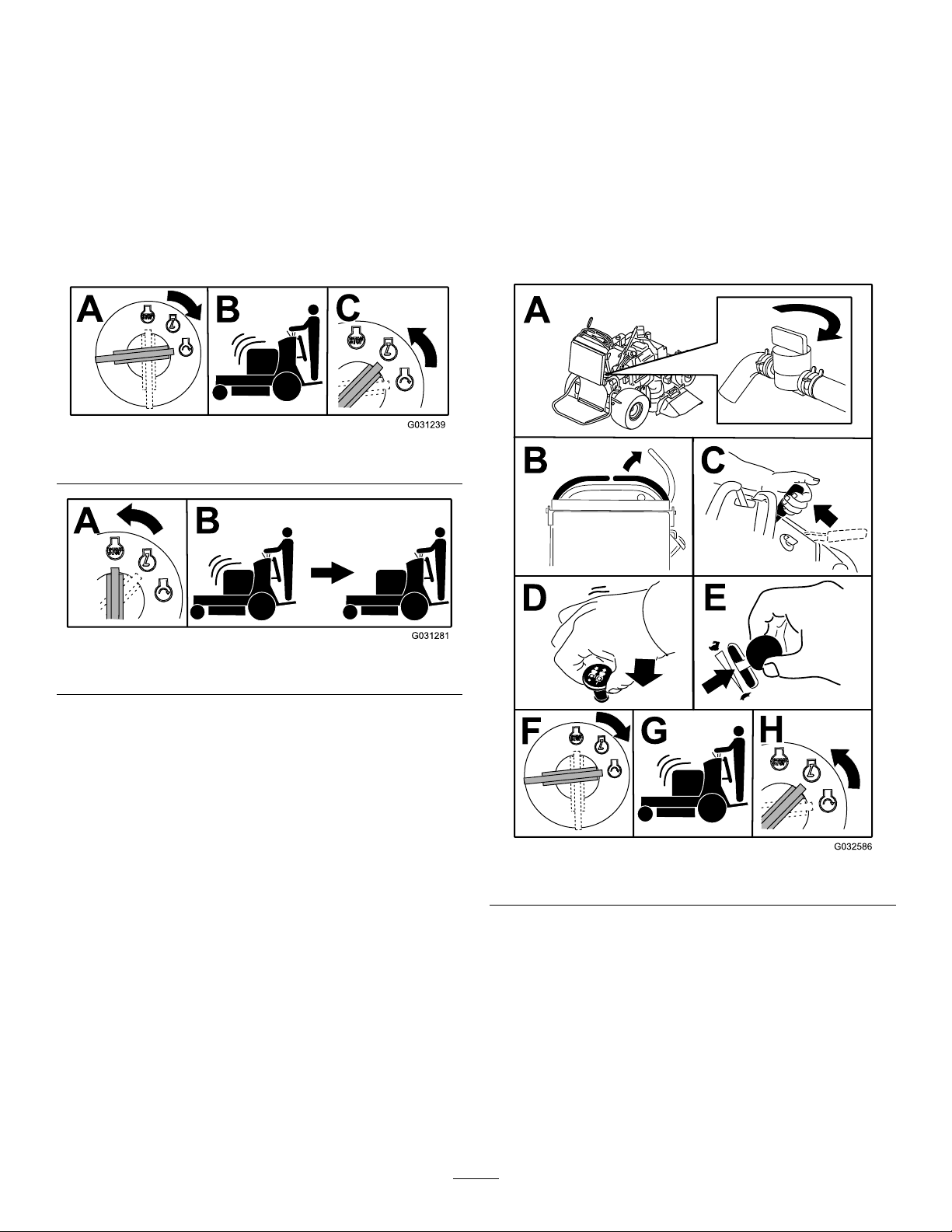
StartingtheEngine
Switch
Important:Donotengagethestarterformore
than5secondsatatime.Iftheenginefailsto
start,wait15secondsbetweenattempts.Failure
tofollowtheseinstructionscanburnoutthe
startermotor.
Note:Youmayneedtorepeatthecycleforstarting
theenginewhenyoustartitforthersttimeafteryou
havelledacompletelyemptyfuelsystemwithfuel.
Figure13
Important:Donotengagethestarterformore
than5secondsatatime.Iftheenginefailsto
start,wait15secondsbetweenattempts.Failure
tofollowtheseinstructionscanburnoutthe
startermotor.
Note:Awarmorhotenginemaynotrequirechoking.
Note:Youmayneedtorepeatthecycleforstarting
theenginewhenyoustartitforthersttimeafteryou
havelledacompletelyemptyfuelsystemwithfuel.
g031239
Figure14
g031281
g032586
Figure15
16
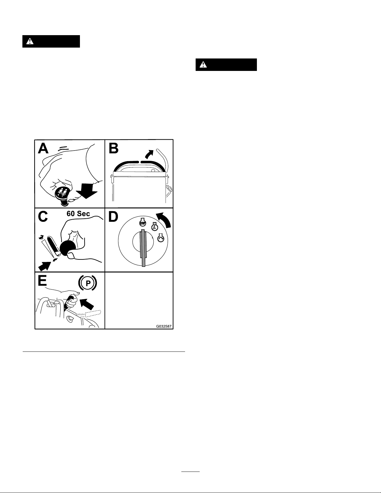
ShuttingOfftheEngine
CAUTION
Childrenorbystandersmaybeinjuredifthey
moveorattempttooperatethemachinewhile
itisunattended.
Alwaysremovethekeyandengagethe
parkingbrakewhenleavingtheoperator’s
position.
OperatingthePlatform
Youcanusethemachinewiththeplatforminthe
upordownposition.Itisyourpreferenceonwhich
positiontouse.
WARNING
Theoperatorplatformisheavyandmaycause
injurywhenyouraiseorlowerit.Carefully
lowerorraisetheoperatorplatform,as
suddenlydroppingitcouldinjureyou.
Lettheengineidleatslowthrottle(turtle)for60
secondsbeforeturningthekeyswitchtotheOFF
position.
•Donotputyourhandsorngersinthe
platform-pivotareawhenloweringor
raisingtheoperatorplatform.
•Makesurethattheplatformissupported
whenyoupullthelatchpinout.
•Makesurethatthelatchsecuresthe
platformwhenfoldingitup.Pushittight
againstthecushionforthelatchpinto
lockintoplace.
•Keepbystandersawayfromthemachine
whenraisingorloweringtheplatform.
OperatingtheMachinewiththe
PlatformUp
Operatethemachinewiththeplatformupforthe
followingconditions:
•Usingthemachineneardrop-offs
•Usingthemachineinsmallareaswherethe
machineistoolarge
•Areaswithlow-hangingbranchesorobstacles
•Loadingthemachinefortransport
•Drivingupslopes
Figure16
Important:Makesurethatthefuel-shutoffvalve
isclosedbeforetransportingorstoringthe
machinetopreventafuelleak.Beforestoringthe
machine,disconnectthesparkplug(s)toprevent
thepossibilityofaccidentalstarting.
Toraisetheplatform,pullthebackoftheplatformup
g032587
sothatthelatchpinandknoblockitintoplace.Push
ittightagainstthecushionforthelatchpintolockit
intoplace.
OperatingtheMachinewiththe
PlatformDown
Operatethemachinewiththeplatformdownforthe
followingconditions:
•Usingthemachineinmostareas
•Drivingacrossslopes
•Drivingdownslopes
Tolowertheplatform,pushtheplatformforward
againstthecushiontoreleasepressureonthelatch
pin,thenpulltheknoboutandlowertheplatform
(Figure17).
17

2.Movetherightmotion-controllevertothecenter,
unlockedposition.
Figure17
1.Platformup
2.Platformdown
3.Pulltheknobouttorelease
theplatform.
DrivingForwardor
Backward
Thethrottlecontrolregulatestheenginespeedas
measuredinrpm(revolutionsperminute).Place
thethrottlecontrolintheFASTpositionforbest
performance.
CAUTION
Themachinecanspinveryrapidly,andyou
maylosecontrolofthemachine,causing
personalinjurytoyouanddamagetothe
machine.
Slowthemachinedownbeforemakingsharp
turns.
g012181
g020531
Figure18
1.Frontreferencebar
2.Leftmotion-controllever
3.Rearreferencebar
4.Rightmotion-controllever
5.Rightmotion-controllever
intheNEUTRAL-LOCK
position
3.Movethespeed-controllevertothedesired
speed.
4.Slowlypushthemotion-controlleversforward
(Figure19).
Note:Theengineshutsoffifyoumovea
motion-controlleverwiththeparkingbrake
engaged.
Note:Thefartheryoumovethemotion-control
leversineitherdirection,thefasterthemachine
movesinthatdirection.
Note:Tostop,pullthemotion-controllevers
backtotheNEUTRALposition.
DrivingForward
1.Disengagetheparkingbrake;refertoOperating
theParkingBrake(page14).
18

Figure19
SideDischargingor
MulchingtheGrass
Thismachinehasahingedgrassdeectorthat
dispersesclippingstothesideanddowntowardthe
turf.
DANGER
Withoutthegrassdeector,dischargecover,
orcompletegrasscatcherassemblymounted
inplace,youandothersareexposedtoblade
contactandthrowndebris.Contactwith
rotatingmowerblade(s)andthrowndebris
causeinjuryordeath.
•Donotremovethegrassdeectorfrom
themachine,becausethegrassdeector
routesmaterialdowntowardtheturf.Ifthe
g009473
grassdeectoriseverdamaged,replaceit
immediately.
•Neverputyourhandsorfeetunderthe
machine.
DrivingBackward
1.Movetherightmotion-controllevertothecenter,
unlockedposition.
2.Slowlypullthemotion-controlleversrearward
(Figure20).
Figure20
•Nevertrytoclearthedischargeareaor
mowerbladesunlessyoureleasethebail
andthepowertakeoff(PTO)isoff.Rotate
thekeytotheOFFposition.Alsoremove
thekeyanddisconnectthewire(s)from
thesparkplug(s).
AdjustingtheHeightofCut
Theheightofcutcanbeadjustedfrom25to127mm
(1to5inches)in6mm(1/4inch)increments.
1.Movetheheight-of-cutlevertothetransport
position(allthewayup).
2.Rotatethepin90degreesandremoveitfrom
theheight-of-cutbracket.
3.Selectaholeintheheight-of-cutbracket
correspondingtotheheight-of-cutdesiredand
insertthepin(Figure21).
4.Pushthebuttonontopandlowerthe
g009474
height-of-cutlevertothepin(Figure21).
19
PositioningtheFlowBafe
Thefollowingguresareforrecommendeduseonly.
Adjustmentsvarybygrasstype,moisturecontent,
andtheheightofthegrass.
Note:Iftheenginepowerdrawsdownandthe
mowergroundspeedisthesame,openthebafe.
PositionA
Thisisthefull,rearposition(seeFigure23).Usethis
positionforthefollowing:
Figure21
1.Height-of-cutholes3.Height-of-cutlever
2.Height-of-cutpin
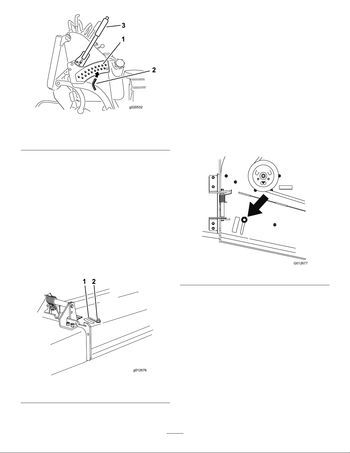
AdjustingtheFlowBafe
Youcanadjustthemower-dischargeowfordifferent
typesofmowingconditions.Positionthecamlock
andbafetoprovidethebestqualityofcut.
1.DisengagethePTO,movethemotion-control
leverstotheNEUTRAL-LOCKposition,and
engagetheparkingbrake.
2.Shutofftheengine,removethekey,andwait
forallmovingpartstostopbeforeleavingthe
operatingposition.
3.Toadjustthebafe,loosenthenut(Figure22).
4.Adjustthebafeandnutintheslottothedesired
dischargeowandtightenthenut.
g020532
•Inshort,lightgrassmowingconditions
•Indryconditions
•Smallergrassclippings
•Propelsgrassclippingsfartherawayfromthe
mower
g012677
Figure23
g012676
Figure22
1.Slot
2.Nut
20

PositionB
UsingWeights
Usethispositionwhenbagging(Figure24).
Figure24
PositionC
Thisisthefull,openposition(Figure25).Usethis
positionforthefollowing:
•Installweightstoimprovebalance.Youcanaddor
removeweightstocreateoptimizedperformance
underdifferentoperatingconditionsandforyour
preference.
•Addorremoveweights1atatimeuntilyou
achievethedesiredhandlingandbalance.
•RefertotheOperator’sManualofattachmentsfor
recommendedweights.
Note:ContactanAuthorizedServiceDealertoorder
aweightkit.
WARNING
Excessiveweightchangescanaffectthe
handlingandoperationofthemachine.
g012678
Thiscouldcauseseriousinjurytoyouor
bystanders.
•Makeweightchangesinsmallincrements
only.
•Evaluatethemachineaftereachweight
changetoensurethatyoucanoperatethe
machinesafely.
•Intall,densegrassmowingconditions
•Inwetconditions
•Lowerstheengine-powerconsumption
•Allowsincreasedgroundspeedinheavyconditions
Figure25
AfterOperation
AfterOperationSafety
GeneralSafety
•Alwaysshutoffthemachine,removetheignition
key,waitforallmovingpartstostop,andallow
themachinetocoolbeforeadjusting,servicing,
cleaning,orstoringit.
•Cleangrassanddebrisfromthecuttingunits,
mufers,andenginecompartmenttohelpprevent
res.Cleanupoilorfuelspills.
•Shutoffthefuelbeforestoringortransportingthe
machine.
•DisengagethePTOwheneveryouaretransporting
ornotusingthemachine.
g012679
•Neverstorethemachineorfuelcontainerwhere
thereisanopename,spark,orpilotlight,such
asonawaterheateroronotherappliances.
•Usefull-widthrampsforloadingthemachineinto
atrailerortruck.
•Tiethemachinedownsecurelyusingstraps,
chains,cable,orropes.Bothfrontandrearstraps
shouldbedirecteddownandoutwardfromthe
machine.
21

UsingtheFuel-Shutoff
PushingtheMachineby
Valve
Closethefuel-shutoffvalvefortransport,maintenance,
andstorage(Figure26).
Ensurethatthefuel-shutoffvalveisopenwhen
startingtheengine.
Hand
Thebypassvalvesallowyoutopushthemachineby
handwithouttheenginerunning.
Important:Alwayspushthemachinebyhand.
Donottowthemachine,becausehydraulic
damagemayoccur.
Important:Donotstartoroperatethemachine
withthebypassvalvesopen.Damagetothe
systemmayoccur.
1.DisengagethePTO,movethemotion-control
leverstotheNEUTRAL-LOCKposition,and
engagetheparkingbrake.
g020864
2.Lowerthemowerdecktothelowestheightof
cut(HOC).
Note:Thisallowsaccesstothebypassvalves.
3.Openthebypassvalveonbothpumpsbyturning
themcounterclockwise1to2turns(Figure27).
Note:Thisallowshydraulicuidtobypassthe
pumpsandthewheelstoturn.
Note:Rotatethebypassvalvesamaximumof
2turnssothatthevalvedoesnotcomeoutof
thebody,causinguidtorunout.
Figure26
1.ONposition2.OFFposition
g008948
g012680
Figure27
1.Pump-bypassvalve
4.Disengagetheparkingbrake.
5.Pushthemachinetothedesiredlocation.
6.Engagetheparkingbrake.
22

7.Closethebypassvalvesbutdonotovertighten
them.
8.Torquethevalvesto12to15N∙m(110to130
in-lb).
TransportingtheMachine
Useaheavy-dutytrailerortrucktotransportthe
machine.Useafull-widthramp.Ensurethatthetrailer
ortruckhasallthenecessarybrakes,lighting,and
markingasrequiredbylaw.Pleasecarefullyreadall
thesafetyinstructions.Knowingthisinformationcould
helpyouorbystandersavoidinjury.Refertoyour
localordinancesfortrailerandtie-downrequirements.
WARNING
Drivingonthestreetorroadwaywithout
turnsignals,lights,reectivemarkings,ora
slow-moving-vehicleemblemisdangerous
andcanleadtoaccidents,causingpersonal
injury.
Donotdrivethemachineonapublicstreet
orroadway.
SelectingaTrailer
WARNING
Loadingamachineontoatrailerortruck
increasesthepossibilityoftip-overandcould
causeseriousinjuryordeath(Figure28).
•Useonlyafull-widthramp;donotuse
individualrampsforeachsideofthe
machine.
•Ensurethatthelengthoframpisatleast4
timesaslongastheheightofthetraileror
truckbedtotheground.
Figure28
1.Full-widthrampinstowed
position
2.Rampisatleast4times
aslongastheheightof
thetrailerortruckbedto
theground
3.H=heightofthetraileror
truckbedtotheground
4.Trailer
LoadingtheMachine
WARNING
Loadingamachineontoatrailerortruck
increasesthepossibilityoftip-overandcould
causeseriousinjuryordeath.
•Useextremecautionwhenoperatinga
machineonaramp.
•Backthemachineuptherampandwalkit
forwarddowntheramp.
•Avoidsuddenaccelerationordeceleration
whiledrivingthemachineonarampas
thiscouldcausealossofcontrolora
tip-oversituation.
g229507
1.Ifusingatrailer,connectittothetowingvehicle
andconnectthesafetychains.
2.Ifapplicable,connectthetrailerbrakesand
lights.
3.Lowertheramp(Figure28).
4.Raisetheplatform.
Important:Alwayskeeptheplatformup
whenloadingandunloadingthemachine.
5.Backthemachineuptheramp(Figure29).
23

Figure29
g031405
1.Backthemachineupthe
ramp.
2.Walkthemachinedown
theramp.
6.Shutofftheengine,removethekey,andengage
theparkingbrake.
7.Tiedownthemachinenearthefrontcaster
wheelsandtherearbumperwithstraps,chains,
cable,orropes(Figure30).Refertolocal
regulationsfortie-downrequirements.
Figure30
g012183
1.Tie-downloops
24

Maintenance
Note:Determinetheleftandrightsidesofthemachinefromthenormaloperatingposition.
CAUTION
Ifyouleavethekeyintheignitionswitch,someonecouldaccidentlystarttheengineand
seriouslyinjureyouorotherbystanders.
Removethekeyfromtheignitionanddisconnectthespark-plugwiresfromthesparkplugs
beforeyoudoanymaintenance.Setthewiresasidesothattheydonotaccidentallycontact
thesparkplugs.
MaintenanceSafety
•Beforeadjusting,cleaning,servicing,orleaving
themachine,dothefollowing:
–Parkthemachineonalevelsurface.
–Disengagethedrives.
–Engagetheparkingbrake.
–Shutofftheengineandremovetheignitionkey .
–Waitforallmovingpartstostop.
–Allowmachinecomponentstocoolbefore
performingmaintenance.
•Donotallowuntrainedpersonneltoservicethe
machine.
•Keepyourhandsandfeetawayfrommoving
parts.Ifpossible,donotmakeadjustmentswith
theenginerunning.
•Carefullyreleasepressurefromcomponentswith
storedenergy.
•Checktheparkingbrakeoperationfrequently.
Adjustandservicethebrakeasneeded.
•Nevertamperwithsafetydevices.Checktheir
properoperationregularly.
•Cleangrassanddebrisfromthecuttingunit,
drives,mufer,andenginetohelppreventres.
Cleanupoilorfuelspills.
•Checkthegrasscatchercomponentsfrequently
andreplacethemwhentheyarewornordamaged.
•Donotrelyonahydraulicsystemtosupportthe
machine;supportthemachinewithjackstands
wheneveryouraisethemachine.
•Keepallpartsingoodworkingconditionandall
hydraulicttingstight.Replaceallworn,damaged,
ormissingpartsanddecals.Keepallfasteners
tighttoensurethatthemachineisinsafeworking
condition.
•Toensureoptimumperformanceandcontinued
safetycerticationofthemachine,useonly
genuineT ororeplacementpartsandaccessories.
Replacementpartsandaccessoriesmadeby
othermanufacturerscouldbedangerous,and
suchusecouldvoidtheproductwarranty.
25

RecommendedMaintenanceSchedule(s)
MaintenanceService
Interval
Aftertherst8hours
Beforeeachuseordaily
Every25hours
Every50hours
Every100hours
MaintenanceProcedure
•Changetheengineoil.
•Checkthehydraulicuidlevel.
•Changethehydrauliclter.
•Checkthesafety-interlocksystem.
•Checktheengine-oillevel.
•Cleantheair-intakescreen(moreoftenindirtyordustyconditions).
•T esttheparkingbrake.
•Checkthebrakeclearance.
•Inspecttheblades.
•Cleanunderthemowerdeck.
•Washthemachine,especiallyafterwinterapplications.
•Cleanfoamair-cleanerelement(moreoftenindirtyordustyconditions).
•Greasethemower-deckidlerarms(moreoftenindirtyordustyconditions).
•Greasetheliftlinkage(moreoftenindirtyordustyconditions).
•Checkthesparkarrester(ifequipped).
•Checkthetirepressure.
•Checkthehydraulicuidlevel.
•Cleanthepaperair-cleanerelement(moreoftenindirtyordustyconditions).
•Changetheengineoil.
•Check,cleanandgapthesparkplug.
•Checkthebattery.
•Checktheelectricclutch.
•Checkandcleanenginecoolingnsandshrouds(moreoftenindirtyordusty
conditions).
•Checkthemower-deckbelt(s).
•Checkthepump-drivebelt.
•Checkthehydraulichoses.
Every200hours
Every250hours
Every300hours
Every500hours
Every800hours
Beforestorage
Yearly
•Replacethepaperair-cleanerelement(moreoftenindirtyordustyconditions).
•Changetheengine-oillter.
•ChangethehydraulicuidwhenusingMobil®1oil.
•Checkandadjustthevalveclearance.SeeanAuthorizedServiceDealer.
•Adjustthecaster-pivotbearing.
•ChangethehydraulicuidwhenusingT oro®HYPR-OIL™500hydraulicuid.
•Changethehydrauliclter.
•Replacethefuellter.
•Paintchippedsurfaces.
•Performallmaintenanceprocedureslistedabovebeforestorage.
•Paintchippedsurfaces.
•Performallmaintenanceprocedureslistedabovebeforestorage.
•Greasethefrontcasterpivots(moreoftenindirtyordustyconditions).
•Greasethecaster-wheelhubs.
•Inspectthebladeboltsandcurvedwashers.Replaceifdamaged.
Important:Refertoyourengineowner’smanualforadditionalmaintenanceprocedures.
26

Pre-Maintenance
Procedures
RaisingtheMowerfor
Access
Youcanraisethefrontofthemowerandsupport
itonitsbackforaccessunderthemachinefor
maintenance.
1.Parkthemachineonalevelsurface,disengage
thePTO,andengagetheparkingbrake.
2.Shutofftheengine,removethekey,andwait
forallmovingpartstostopbeforeleavingthe
operatingposition.
3.Raisetheplatform;refertoOperatingthe
MachinewiththePlatformUp(page17).
4.Removethebattery;refertoRemovingthe
Battery(page37).
Figure31
g012681
Figure32
1.Cap
2.Pieceofplastic
7.With2people,raisethefrontofthemowerso
thatitrestsonthedrivetiresandtheplatform
intheupposition.
8.Performanymaintenanceonthemachine.
9.With2people,lowerthefrontofthemowerto
theground.
10.Removetheplasticunderthehydraulic-tank
cap.
11.Installthebatteryforthemachine.
g012597
3.Hydraulictank
1.Wingnut
2.Batterycover5.Battery
3.Negative(–)batterycable
5.Drainthefuelfromthefueltank;refertoDraining
theFuelT ank(page35).
6.Removethecapofthehydraulictankandplace
apieceofplasticovertheopeningandinstall
thehydrauliccap.
4.Positive(+)batterycable
Note:Thissealsthehydraulictankand
preventsitfromleakingout.
27

ReleasingtheCushionfor
RearAccess
Youcanreleasethecushionforrearaccesstothe
machineformaintenanceoradjustment.
1.Lowertheplatform.
2.Removethehairpincottersoneachsideofthe
cushion.
3.Slidethelargewasherswithplasticbushings
totheinside.
1.Removethebattery.
Figure33
2.With2people,liftthefront
endofthemower(ensure
thattheplatformisup).
g009448
4.Removethecushionandlowerittotheplatform.
5.Performanymaintenanceoradjustmentonthe
machine.
6.Raisethecushionandslideitontothepinson
bothsidesofthemachine(Figure34).
7.Slidethelargewasherswithplasticbushings
intothecushionbracketandsecurethemwith
ahairpin-cotterpin(Figure34).
g009461
g032596
Figure34
28

Lubrication
GreasingtheMachine
ServiceInterval:Every50hours—Greasethe
mower-deckidlerarms(moreoften
indirtyordustyconditions).
Every50hours—Greasetheliftlinkage(more
oftenindirtyordustyconditions).
Greasetype:Lithiumormolybdenumgrease
1.Parkthemachineonalevelsurface,disengage
thePTO,andengagetheparkingbrake.
2.Shutofftheengine,removethekey ,andwait
forallmovingpartstostopbeforeleavingthe
operatingposition.
3.Cleanthegreasettingswitharag.
Note:Scrapeanypaintoffthefrontofthe
tting(s).
4.Connectagreaseguntothetting.
5.Pumpgreaseintothettingsuntilgreasebegins
tooozeoutofthebearings.
6.Wipeupanyexcessgrease.
Usethefollowinggraphicsforlocatingthegrease
points.
g012594
Figure36
Modelswitha102cmor40-InchMowerDeck
g012682
Figure37
AllModels
Figure35
Modelswitha91cmor36-InchMowerDeck
GreasingtheFrontCaster
g012593
Pivots
ServiceInterval:Y early
Greasetype:Lithiumormolybdenumgrease
1.Removethedustcapandadjustthecaster
pivots;refertoAdjustingtheCaster-Pivot
Bearing(page41).
Note:Keepthedustcapoffuntilyouhave
nishedgreasingthecasterpivots.
2.Removethehexplug.
3.Threadagreasettingintothehole.
4.Pumpgreaseintothettinguntilitoozesout
aroundthetopbearing.
5.Removethegreasettingfromthehole.
6.Installthehexpluganddustcap.
29

GreasingtheCaster-Wheel
Hubs
ServiceInterval:Y early
Greasetype:Lithiumormolybdenumgrease
10.Inserttheassemblednutandaxleintothewheel
onthesideofthewheelwiththenewsealand
bearing.
11.Withtheopenendofthewheelfacingup,ll
theareainsidethewheelaroundtheaxlefullof
general-purposegrease.
1.Parkthemachineonalevelsurface,disengage
thePTO,andengagetheparkingbrake.
2.Shutofftheengine,removethekey ,andwait
forallmovingpartstostopbeforeleavingthe
operatingposition.
3.Removethecasterwheelfromthecasterforks.
4.Removethesealguardsfromthewheelhub
(Figure38).
Figure38
1.Sealguard2.Spacernutwithwrench
ats
12.Insertthesecondbearingandthenewsealinto
thewheel.
13.Applyathread-lockingadhesivetothesecond
spacernut,threadingitontotheaxlewiththe
wrenchatsfacingoutward.
14.T orquethenutto8to9N∙m(71to80in-lb),
loosenit,thentorqueitto2to3N∙m(20to25
in-lb).
Note:Makesurethattheaxledoesnotextend
beyondeithernut.
15.Installthesealguardsoverthewheelhuband
insertthewheelintothecasterfork.
16.Installthecasterboltandtightenthenutfully.
Important:Topreventsealandbearingdamage,
checkthebearingadjustmentoftenbyspinning
thecasterwheel.Thewheelshouldnotspinfreely
(morethan1or2revolutions)orhaveanyside
g006115
play.Ifthewheelspinsfreely ,adjustthetorque
onthespacernutuntilthereisaslightamountof
drag,andapplythread-lockingadhesive.
5.Remove1spacernutfromtheaxleassemblyin
thecasterwheel.
Note:Thread-lockingadhesivehasbeen
appliedtolockthespacernutstotheaxle.
Removetheaxle(withtheotherspacernutstill
assembledtoit)fromthewheelassembly.
6.Pryouttheseals,inspectbearingsforwearor
damage,andreplacethemifnecessary .
7.Packthebearingswithageneral-purpose
grease.
8.Insert1bearingand1newsealintothewheel.
Note:Youmustreplacetheseals.
9.Ifbothspacernutsintheaxleassembly
havebeenremoved(orbrokenloose),apply
athread-lockingadhesiveto1spacernut,
threadingitontotheaxlewiththewrenchats
facingoutward.
Note:Donotthreadthespacernutallof
thewayontotheendoftheaxle.Leave
approximately3mm(1/8inch)fromtheouter
surfaceofthespacernuttotheendoftheaxle
insidethenut.
30

EngineMaintenance
EngineSafety
•Shutofftheenginebeforecheckingtheoilor
addingoiltothecrankcase.
•Keepyourhands,feet,face,clothing,andother
bodypartsawayfromthemuferandotherhot
surfaces.
ServicingtheAirCleaner
ServiceInterval:Every300hours
Inspectthefoamandpaperelementsandreplace
themiftheyaredamagedorexcessivelydirty.
Important:Donotoilthefoamorpaperelement.
RemovingtheFoamandPaper
Figure39
1.Cover
2.Hoseclamp4.Foamelement
3.Paperelement
g012619
Elements
1.Parkthemachineonalevelsurface,disengage
thePTO,andengagetheparkingbrake.
2.Shutofftheengine,removethekey ,andwait
forallmovingpartstostopbeforeleavingthe
operatingposition.
3.Cleanaroundtheaircleanertopreventdirtfrom
gettingintotheengineandcausingdamage
(Figure39).
4.Loosenthecoverknobsandremovethe
air-cleanercover(Figure39).
5.Loosenthehoseclampandremovethe
air-cleanerassembly(Figure39).
6.Carefullypullthefoamelementoffthepaper
element(Figure39).
CleaningtheFoamAir-Cleaner
Element
ServiceInterval:Every25hours
1.Washthefoamelementinliquidsoapand
warmwater.Whentheelementisclean,rinse
itthoroughly.
2.Drytheelementbysqueezingitinacleancloth.
Important:Replacethefoamelementifit
istornorworn.
ServicingthePaperAir-Cleaner
Element
ServiceInterval:Every100hours—Cleanthepaper
air-cleanerelement(moreoftenin
dirtyordustyconditions).
Every200hours—Replacethepaperair-cleaner
element(moreoftenindirtyordustyconditions).
1.Cleanthepaperelementbytappingitgentlyto
removedust.
Note:Ifitisverydirty ,replacethepaper
elementwithanewone.
2.Inspecttheelementfortears,anoilylm,or
damagetotherubberseal.
3.Replacethepaperelementifitisdamaged.
Important:Donotcleanthepaperlter.
31

InstallingtheFoamandPaper
Elements
Important:Topreventenginedamage,always
operatetheenginewiththecompletefoamand
paperair-cleanerassemblyinstalled.
1.Carefullyslidethefoamelementontothepaper
air-cleanerelement(Figure39).
2.Placetheair-cleanerassemblyontothebaseof
theaircleanerorhoseandsecureit(Figure39).
3.Placetheair-cleanercoverintopositionand
tightenthecoverknob(Figure39).
ServicingtheEngineOil
runenginewithoilbelowthelowmarkbecause
theenginemaybedamaged.
1.Parkthemachineonalevelsurface,disengage
thePTO,andengagetheparkingbrake.
2.Shutofftheengine,removethekey ,andwait
forallmovingpartstostopbeforeleavingthe
operatingposition.
3.Checktheengine-oillevelasshownin(Figure
41).
Engine-OilSpecications
OilType:Detergentoil(APIserviceSJorhigher)
EngineOilCapacity:1.7L(57oz)withthelter;
1.5L(51oz)withoutthelter
Viscosity:Refertothetablebelow:
Figure40
g020534
g004216
CheckingtheEngine-OilLevel
ServiceInterval:Beforeeachuseordaily
Note:Checktheoilwhentheengineiscold.
WARNING
Contactwithhotsurfacesmaycausepersonal
injury.
Keepyourhands,feet,face,clothingand
otherbodypartsawaythemuferandother
hotsurfaces.
Important:Donotoverllthecrankcasewithoil
becausedamagetotheenginemayresult.Donot
g194611
Figure41
32

ChangingtheEngineOil
ServiceInterval:Aftertherst8hours
Every100hours
Note:Disposeoftheusedoilatarecyclingcenter.
1.Parkthemachinesothatthedrainsideisslightly
lowerthantheoppositesidetoassuretheoil
drainscompletely.
2.DisengagethePTO,movethemotion-control
leverstotheNEUTRAL-LOCKposition,and
engagetheparkingbrake.
3.Shutofftheengine,removethekey ,andwait
forallmovingpartstostopbeforeleavingthe
operatingposition.
4.ChangetheengineoilasshowninFigure42.
g194610
Figure43
Figure42
5.Slowlypourapproximately80%ofthespecied
oilintothellertubeandslowlyaddthe
additionaloiltobringittotheFullmark(Figure
43).
g020534
6.Starttheengineanddrivetoaatarea.
7.Checktheoillevelagain.
ChangingtheEngine-OilFilter
ServiceInterval:Every200hours
Note:Changetheengine-oilltermorefrequently
whenoperatingconditionsareextremelydustyor
sandy.
1.Draintheoilfromtheengine;refertoChanging
theEngineOil(page33).
2.Changetheengine-oillter(Figure44).
g032598
33

RemovingtheSparkPlug
1.Parkthemachineonalevelsurface,disengage
thePTO,andengagetheparkingbrake.
2.Shutofftheengine,removethekey ,andwait
forallmovingpartstostopbeforeleavingthe
operatingposition.
g020534
3.RemovethesparkplugasshowninFigure45.
g012187
Figure44
Note:Ensurethattheoil-ltergaskettouches
theengine,thenrotatethelteranextra3/4turn.
3.Fillthecrankcasewiththepropertypeofnew
oil;refertoEngine-OilSpecications(page32).
ServicingtheSparkPlug
ServiceInterval:Every100hours
g027478
Figure45
CheckingtheSparkPlug
Important:Donotcleanthesparkplug(s).
Alwaysreplacethesparkplug(s)whenithasa
blackcoating,wornelectrodes,anoilylm,or
cracks.
g027477
Ifyouseelightbrownorgrayontheinsulator,the
engineisoperatingproperly.Ablackcoatingonthe
insulatorusuallymeanstheaircleanerisdirty.
Setthegapto0.75mm(0.03inch).
Ensurethattheairgapbetweenthecenterandside
electrodesiscorrectbeforeinstallingthesparkplug.
Useasparkplugwrenchforremovingandinstalling
thesparkplug(s)andagappingtool/feelergaugeto
checkandadjusttheairgap.Installanewspark
plug(s)ifnecessary.
Type:NGK®BPR4ESorequivalent
Airgap:0.75mm(0.03inch)
g027479
Figure46
34

InstallingtheSparkPlug
FuelSystem
Maintenance
DrainingtheFuelTank
Note:Useasyphonpumptodrainfuelfromthetank.
Youcanpurchaseasyphonpumpatahardwarestore.
DANGER
Incertainconditions,fuelisextremely
ammableandhighlyexplosive.Areor
explosionfromfuelcanburnyou,others,and
candamageproperty.
Figure47
CheckingtheSpark
Arrester
ForMachineswithaSpark
Arrester
ServiceInterval:Every50hours
WARNING
Hotexhaust-systemcomponentsmayignite
fuelvaporsevenafteryoushutofftheengine.
Hotparticlesexhaustedduringengine
operationmayigniteammablematerials,
resultinginpersonalinjuryorproperty
damage.
Donotrefuelorruntheengineunlessthe
sparkarresterisinstalled.
g027661
•Performanyfuel-relatedmaintenance
whentheengineiscold.Dothisoutdoors
inanopenarea.Wipeupanyfuelthat
spills.
•Neversmokewhendrainingfuel,andstay
awayfromanopenameorwhereaspark
mayignitethefuelfumes.
1.Parkthemachineonalevelsurface,disengage
thePTO,andengagetheparkingbrake.
2.Shutofftheengine,removethekey ,andwait
forallmovingpartstostopbeforeleavingthe
operatingposition.
3.Cleanaroundthefuelcaptopreventdebrisfrom
gettingintothefueltank(Figure48).
4.Removethefuelcap.
5.Insertasyphonpumpintothefueltank.
6.Usingthesyphonpump,drainthefuelintoa
cleanfuelcan(Figure48).
7.Wipeupanyspilledfuel.
1.Parkthemachineonalevelsurface,disengage
thePTO,andengagetheparkingbrake.
2.Shutofftheengine,removethekey ,andwait
forallmovingpartstostopbeforeleavingthe
operatingposition.
3.Waitforthemufertocool.
4.Ifyouseeanybreaksinthescreenorwelds,
replacethearrester.
5.Ifthescreenisplugged,removethearrester,
shakelooseparticlesoutofthearrester,and
cleanthescreenwithawirebrush(soakthe
screeninsolventifnecessary).
6.Installthearresterontheexhaustoutlet.
35

Figure48
1.Fuelcap
ReplacingtheFuelFilter
ServiceInterval:Every800hours/Yearly(whichever
comesrst)
Donotinstalladirtylterifitisremovedfromthefuel
line.
Note:Wipeupanyspilledfuel.
1.Parkthemachineonalevelsurface,disengage
thePTO,andengagetheparkingbrake.
2.Shutofftheengine,removethekey ,andwait
forallmovingpartstostopbeforeleavingthe
operatingposition.
3.Closethefuel-shutoffvalve;refertoUsingthe
Fuel-ShutoffValve(page22).
4.ReplacethefuellterasshowninFigure49.
g020861
g033082
Figure49
36

ElectricalSystem
Maintenance
ElectricalSystemSafety
•Disconnectthebatteryorremovethespark-plug
wirebeforemakinganyrepairs.Disconnectthe
negativeterminalrstandthepositiveterminal
last.Connectthepositiveterminalrstand
negativelast.
•Chargethebatteryinanopen,well-ventilated
area,awayfromsparksandames.Unplugthe
chargerbeforeconnectingordisconnectingthe
battery.Wearprotectiveclothinganduseinsulated
tools.
ServicingtheBattery
ServiceInterval:Every100hours
Alwayskeepthebatterycleanandfullycharged.Use
apapertoweltocleanthebatterycase.Ifthebattery
terminalsarecorroded,cleanthemwithasolutionof
fourpartswaterand1partbakingsoda.Applyalight
coatingofgreasetothebatteryterminalstoprevent
corrosion.
Voltage:12V
RemovingtheBattery
1.Parkthemachineonalevelsurface,disengage
thePTO,andengagetheparkingbrake.
2.Shutofftheengine,removethekey ,andwait
forallmovingpartstostopbeforeleavingthe
operatingposition.
3.RemovethebatteryasshowninFigure50.
g273408
Figure50
37

ChargingtheBattery
InstallingtheBattery
WARNING
Chargingthebatteryproducesgassesthat
canexplode.
Neversmokenearthebatteryandkeepsparks
andamesawayfrombattery.
Important:Alwayskeepthebatteryfullycharged
(1.265specicgravity)topreventbatterydamage
whenthetemperatureisbelow0°C(32°F).
1.Removethebatteryfromthechassis;referto
RemovingtheBattery(page37).
2.Checktheelectrolytelevel.
3.Ensurethatthellercapsareinstalledonthe
battery.
4.Chargethebatteryfor1hourat25to30Aor6
hoursat4to6A.
5.Whenthebatteryisfullycharged,unplugthe
chargerfromtheelectricaloutlet,anddisconnect
thechargerleadsfromthebatteryposts(Figure
51).
InstallthebatteryasshowninFigure52.
6.Installthebatteryontothemachineandconnect
thebatterycables;refertoInstallingtheBattery
(page38).
Note:Donotrunthemachinewiththebattery
disconnected;electricaldamagemayoccur.
Figure51
1.Positivebatterypost
2.Negativebatterypost
3.Red(+)chargerlead
4.Black(-)chargerlead
g273407
Figure52
g000538
38

ServicingtheFuses
DriveSystem
Theelectricalsystemisprotectedbyfuses.It
requiresnomaintenance.Ifafuseblows,checkthe
componentorcircuitforamalfunctionorshort.
1.Parkthemachineonalevelsurface,disengage
thePTO,andengagetheparkingbrake.
2.Shutofftheengine,removethekey ,andwait
forallmovingpartstostopbeforeleavingthe
operatingposition.
3.Releasetheoperatorcushionfromtherearof
themachine.
4.Pulloutthefuseandreplaceit(Figure53).
5.Installtheoperatorcushion.
Maintenance
AdjustingtheTracking
Ifyoupushbothmotion-controlleversforwardthe
samedistanceandthemachinepullsto1side,adjust
thetrackingasfollows.
1.Parkthemachineonalevelsurface,disengage
thePTO,andengagetheparkingbrake.
2.Shutofftheengine,removethekey ,andwait
forallmovingpartstostopbeforeleavingthe
operatingposition.
3.Releasethecushionfromtherearofthe
machine.
4.Rotatetherightcableadjustmenttopositionthe
rightmotion-controlleverinthecenterofthe
control-panelneutral-lockslot(Figure55).
1.Optionalaccessoryfuse
(15A)
2.Power-takeoff(PTO)fuse
(10A)
Figure53
3.Chargefuse(25A)
4.Mainfuse(30A)
g032599
g015241
Figure54
1.Leftmotion-controllever
2.Rightmotion-controllever4.Alignthecontrollevers
5.Rotatetheleftcableadjustmenttomatchtheleft
wheelspeedtothepreviouslysetrightwheel
speed.
6.Adjustinquarter-turnincrementsuntilthe
machinetracksstraight.
3.NEUTRAL-LOCKposition
fronttoback.
Note:Adjustonlytheleftcabletomatchtheleft
wheelspeedtotherightwheelspeed.Donot
adjusttherightwheelspeedasthispositionsthe
rightmotion-controlleveroutofthecenterfor
thecontrol-panelneutral-lockslot.
39

Figure55
3.Checkthedistanceofthebolttotheproximity
switch;itneedstobebetween0.51to1.02mm
(0.02to0.04inches)asshowninFigure56.
4.Ifadjustmentisneeded,loosenthejamnutand
adjustthebolttothecorrectdistance.
5.Tightenthejamnutafteradjustingthebolt
(Figure56).
6.T estthesafety-interlocksystembeforeoperating
themachine.
g017848
1.Leftcableadjustment
2.Cablelock
3.Rightcableadjustment
7.Checkforpropertracking.
Note:Ifthemachinedoesnotstartafter
adjustingthetracking,makesurethatthe
proximityswitchtargetalignswiththebolt
attachedtothemotion-controllever;referto
AdjustingtheProximitySwitch(page40).
8.Repeatthecableadjustmentuntilthetracking
iscorrect.
9.Checkthatthemachinedoesnotcreepfrom
neutralwiththeparkbrakesdisengaged.
Important:Donotrotatethelinkagetoofar,as
thismaycausethemachinetocreepinneutral.
AdjustingtheProximity
Switch
Usethisprocedureifthemachinedoesnotstartafter
adjustingthetracking.
1.Ensurethattheboltattachedtothe
motion-controlleveralignswiththe
proximity-switchtarget(Figure56).
c:\data\documentum\checkout\g015609
Figure56
1.Proximity-switchtarget4.Boltattachedtothe
2.Proximityswitch
3.Boltsandnuts6.Jamnut
motion-controllever
5.0.51to1.02mm(0.02to
0.04inches)
2.Ifneeded,loosentheboltsandadjustthe
proximityswitchuntilthetargetalignswiththe
boltattachedtothemotion-controllever(Figure
56).
40

CheckingtheTirePressure
AdjustingtheCaster-Pivot
ServiceInterval:Every50hours/Monthly(whichever
comesrst)
Maintaintheairpressureinthereartiresat83to97
kPa(12to14psi).
Important:Uneventirepressurecancausean
unevencut.
Note:Thefronttiresaresemi-pneumatictiresanddo
notrequireair-pressuremaintenance.
Figure57
Bearing
ServiceInterval:Every500hours/Yearly(whichever
comesrst)
1.Parkthemachineonalevelsurface,disengage
thePTO,andengagetheparkingbrake.
2.Shutofftheengine,removethekey ,andwait
forallmovingpartstostopbeforeleavingthe
operatingposition.
3.Removethedustcapfromthecasterandtighten
thelocknut(Figure58).
4.Tightenthelocknutuntilthespringwashersare
at,andthenbackoff1/4turntoproperlysetthe
preloadonthebearings(Figure58).
Important:Makesurethatthespring
washersareinstalledcorrectlyasshownin
Figure58.
5.Installthedustcap(Figure58).
g001055
g001297
Figure58
1.Springwashers
2.Locknut
41
3.Dustcap

AdjustingtheElectric
CoolingSystem
Clutch
ServiceInterval:Every100hours—Checkthe
electricclutch.
Theclutchisadjustabletoensureproperengagement
andproperbraking.
1.Parkthemachineonalevelsurface,disengage
thePTO,andengagetheparkingbrake.
2.Shutofftheengine,removethekey ,andwait
forallmovingpartstostopbeforeleavingthe
operatingposition.
3.Inserta0.4to0.5mm(0.01to0.02inch)feeler
gaugethroughaninspectionslotinthesideof
theassembly.
Note:Ensurethatitisbetweenthearmature
andtherotorfrictionsurfaces.
Note:Thegapneedstobeatleast0.4mm
(0.02inches)andnotmorethan0.5mm(0.02
inches).
4.Ifadjustmentisneeded,usea0.4mm(0.02
inches)feelergaugetoseteachofthe3
adjustment-slotpositions.
5.Tightenthelocknutsuntilthereisslightbinding
onthefeelergaugebutitcanbemovedeasily
withintheairgap(Figure59).
6.Repeatthisfortheremainingslots.
7.Checkeachslotagainandmakeslight
adjustmentsuntilthefeelergaugeisbetween
therotorandarmaturewithveryslightcontact
betweenthem.
Maintenance
CleaningtheAir-Intake
Screen
ServiceInterval:Beforeeachuseordaily
Beforeeachuse,removeanybuildupofgrass,dirt,
orotherdebrisfromthecylinderandcylinder-head
coolingns,air-intakescreenontheywheelend,
andthecarburetor-governorleversandlinkage.This
helpsensureadequatecoolingoftheengineandthe
correctenginespeed,anditreducesthepossibilityof
overheatingormechanicaldamagetotheengine.
CleaningtheCooling
System
ServiceInterval:Every100hours—Checkand
cleanenginecoolingnsand
shrouds(moreoftenindirtyordusty
conditions).
1.Parkthemachineonalevelsurface,disengage
thePTO,andengagetheparkingbrake.
2.Shutofftheengine,removethekey ,andwait
forallmovingpartstostopbeforeleavingthe
operatingposition.
3.Removetheair-intakescreenandthefan
housing(Figure60).
4.Cleanthedebrisandgrassfromtheengine
parts.
Figure59
1.Adjustingnut3.Feelergauge
2.Slot
5.Installtheair-intakescreenandfanhousing
(Figure60).
g009482
42

1.Guard
2.Engineair-intakescreen
3.Bolt
Figure60
BrakeMaintenance
TestingtheParkingBrake
ServiceInterval:Beforeeachuseordaily
Beforeeachuse,testtheparkingbrakeonbotha
levelsurfaceandslope.
Alwaysengagetheparkingbrakewhenyoustopthe
machineorleaveitunattended.Iftheparkingbrake
doesnotholdsecurely ,adjustit.
1.DisengagethePTOandengagetheparking
brake
2.Shutofftheengine,removethekey ,andwait
forallmovingpartstostopbeforeleavingthe
operatingposition.
3.Disengagetheparkingbrake.
g017626
4.Fanhousing
5.Screw
4.Engagethebrakeleverandensurethatthe
machinedoesnotmove.
5.Adjustthebrakeifneeded.
CheckingtheBrake
Clearance
ServiceInterval:Beforeeachuseordaily
Important:Ensurethatthemachineisonalevel
surfacewhencheckingandadjustingthebrake.
1.Parkthemachineonalevelsurface,disengage
thePTO,andengagetheparkingbrake.
2.Shutofftheengine,removethekey ,andwait
forallmovingpartstostopbeforeleavingthe
operatingposition.
3.Checkthetirepressure;refertoCheckingthe
TirePressure(page41).
4.Disengagetheparkingbrake;refertoOperating
theParkingBrake(page14).
5.Withthebrakedisengaged,measurethe
distancebetweenthebrakebarandthetireon
eachside.
6.Usingthesidewiththesmallestclearance,
ensurethatthedistanceisbetween3and6mm
(1/8and1/4inches)asshowninFigure61);
refertoAdjustingtheBrakes(page44)ifthe
distanceisincorrect.
43

AdjustingtheBrakes
1.Parkthemachineonalevelsurface,disengage
thePTO,andengagetheparkingbrake.
2.Shutofftheengine,removethekey ,andwait
forallmovingpartstostopbeforeleavingthe
operatingposition.
3.Disengagetheparkingbrake.
4.T oadjustthebrake,removetheclevispinand
hairpincotterfromthelower-brakeleverand
yoke(Figure62).
5.Adjusttheyoke(Figure61).
Note:Thedistancebetweenthebrakebarand
thetireneedsbebetween3and6mm(1/8and
1/4inches).
Figure61
1.Tire
2.Brakebar4.Measurethesmallest
3.Clearancebetween3and
6mm(1/8and1/4inches)
clearancebetweenthebar
andtire.
g021180
Note:T otightenthebrake,rotatetheyokeup.
Toloosenthebrake,rotatetheyokedown.
6.Checkthebrakeoperationagain;refertoT esting
theParkingBrake(page43).
7.Securetheyoketothelower-brakeleverwith
theclevispinandhairpincotter(Figure62).
Figure62
1.Yoke3.Lower-brakelever
2.Clevispin
44
4.Hairpincotter
g013291

BeltMaintenance
CheckingtheBelts
ServiceInterval:Every100hours—Checkthe
mower-deckbelt(s).
Checkbeltsforcracks,frayededges,burnmarks,
wear,signsofoverheating,oranyotherdamage.
Thesignsofawornmowerbeltaresquealingwhile
thebeltisrotating,bladesslippingwhileyouare
cuttinggrass,frayedbeltedges,burnmarks,and
cracks.Replacethemowerbeltifyoudetectanyof
thesesigns.
1.Belt
2.Spring-loadedidlerpulley
g012738
Figure63
3.Spring
ReplacingtheMower-Deck
Belt
Important:Thefastenersonthecoversofthis
machinearedesignedtoremainonthecover
afterremoval.Loosenallofthefastenerson
eachcoverafewturnssothatthecoverisloose
butstillattached,thengobackandloosenthem
untilthecovercomesfree.Thispreventsyou
fromaccidentallystrippingtheboltsfreeofthe
retainers.
Machineswitha91cm(36-inch)
Deck
1.Parkthemachineonalevelsurface,disengage
thePTO,andengagetheparkingbrake.
2.Shutofftheengine,removethekey ,andwait
forallmovingpartstostopbeforeleavingthe
operatingposition.
3.Loosentheboltsandremovetherightbeltcover
withtheboltattachedtoit.
Machineswitha102cm(40-inch)
Deck
1.Parkthemachineonalevelsurface,disengage
thePTO,andengagetheparkingbrake.
2.Shutofftheengine,removethekey ,andwait
forallmovingpartstostopbeforeleavingthe
operatingposition.
3.Loosentheboltsandremovethebeltcovers
withtheboltsattachedtothem.
4.Removethespringfromtheanchorpostonthe
idler-pulleyarm(Figure63).
4.Removethespringfromtheanchorpostonthe
idler-pulleyarm(Figure63).
5.Removethewornmowerbelt(Figure63).
6.Installthenewmowerbeltaroundtheclutch
pulley,thedeckpulleys,andtheidlerpulley
(Figure63).
7.Installthespringontotheanchorpostonthe
idler-pulleyarm(Figure63).
8.Installthebeltcoverontothemowerdeckand
securethebolt.
Figure64
1.Belt
2.Spring
5.Removetherightmower-deckbelt(Figure64).
6.Ifyouarereplacingtheleftmower-deckbelt,
continueasfollows,otherwiseproceedtostep7.
A.Removethespringfromtheanchorposton
theidler-pulleyarm(Figure65).
B.Removethewornmowerbelt(Figure65).
45
3.Spring-loadedidlerpulley
g012707

C.Installanewmowerbeltaroundthedeck
pulleys,theclutchpulley ,andtheidler
pulley(Figure65).
Figure65
g012737
1.Belt
2.Spring-loadedidlerpulley
3.Spring
7.Installthepreviouslyremovedoranewmower
beltaroundtherightdeckpulleysandidler
pulley(Figure64).
8.Installthespringontotheanchorpostonthe
idler-pulleyarm(Figure63).
9.Installthebeltcoversontothemowerdeckand
securethebolts.
ReplacingthePump-Drive
Belt
ServiceInterval:Every100hours—Checkthe
pump-drivebelt.
1.Parkthemachineonalevelsurface,disengage
thePTO,andengagetheparkingbrake.
2.Shutofftheengine,removethekey ,andwait
forallmovingpartstostopbeforeleavingthe
operatingposition.
3.Removethemower-deckbelt;refertoReplacing
theMower-DeckBelt(page45).
4.Tiltthemachine;refertoRaisingtheMowerfor
Access(page27).
5.Removetheshoulderbolt,thenut,andthe
washerfromtheenginedeckandconnected
spring(Figure66).
Figure66
1.Hydraulicpumps
2.Idlerpulley5.Pump-drivebelt
3.Clutchpulley6.Shoulderbolt,nut,and
4.Clutchretainer
washer
6.Removethepump-drivebelt(Figure66).
7.Installthenewbeltaroundtheclutchandthe2
pumppulleys.
8.Installthespringontotheshoulderboltand
washer,andconnectittotheenginedeckwith
thenut(Figure66).
9.Lowerthemachinetotheoperatingposition.
10.Installthemower-deckbelt;refertoReplacing
theMower-DeckBelt(page45).
g015402
46

ControlsSystem
Maintenance
AdjustingtheRight
Motion-ControlLever
Ifthemotion-controlleversdonotalignhorizontally,
adjusttherightmotion-controllever.
Note:Adjustthehorizontalalignmentbefore
adjustingthefronttobackalignment.
1.Parkthemachineonalevelsurface,disengage
thePTO,andengagetheparkingbrake.
2.Shutofftheengine,removethekey ,andwait
forallmovingpartstostopbeforeleavingthe
operatingposition.
3.Pushtherightmotion-controlleverdownoutof
theNEUTRAL-LOCKposition(Figure67).
4.Checkiftherightmotion-controlleveraligns
horizontallywiththeleftmotion-controllever
(Figure67).
Figure68
1.Cam
7.Adjustthecamuntilitalignswiththeleft
motion-controlleverandtightenthenutforthe
cam.
2.Nut
g024053
Figure67
1.Leftmotion-controllever3.Checkthehorizontal
2.Rightmotion-controllever
intheNEUTRAL-LOCK
position
alignmenthere.
4.Rightmotion-controllever
Note:Toadjusttherightmotion-controllever
horizontally,adjustthecam.
5.Releasethecushionfromtherearofthe
machine.
6.Loosenthenutholdingthecam(Figure68).
Note:Movingthecamclockwise(inthevertical
position)lowersthehandle,whilemovingit
counterclockwise(intheverticalposition)raises
thehandle.
Important:Ensurethattheatportionofthe
camdoesnotgoaboveaverticalposition
(rightorleft);otherwiseyoumaydamagethe
g009436
switch.
AdjustingtheNeutral
Positionforthe
Motion-ControlLevers
Important:Ensurethatthetrackingiscorrect
afteradjustingthemotion-controllevers(Figure
69).
Note:Adjustthehorizontalalignmentbefore
adjustingthefronttobackalignment.
Ifthemotion-controlleversdonotalignfronttoback
ortherightcontrolleverdoesnotmoveeasilyinto
theNEUTRAL-LOCKposition,adjusttheneutralposition
forthelevers.
1.Afteryounishthehorizontalalignment,check
thefront-to-backalignmentbyslightlypushing
themotion-controlleversforwardtotakeupany
47

slackinthelinkageforthecontrollevers(Figure
69).
Figure69
g012706
1.Leftmotion-controllever
2.Rightmotion-controllever4.Alignthemotion-control
3.NEUTRAL-LOCKposition
leversfronttoback.
2.Ensurethattherightmotion-controllevermoves
easilyintotheNEUTRAL-LOCKposition.
Note:Turnthecableadjustmentclockwiseto
movethemotion-controlhandleforward.Turn
thecableadjustmentcounterclockwisetomove
themotion-controlhandlerearward.
3.Rotatethecableadjustmentontherightside
whenadjustmentisneeded.
Note:Adjustthecableadjustmentin
quarter-turnincrements.
4.Aftertherightmotion-controllevermoveseasily
intotheNEUTRAL-LOCKposition,adjusttheleft
motion-controllevertoalignitwiththeright
motion-controllever.
5.Checkforpropertracking;refertoAdjustingthe
Tracking(page39).
6.Installthecablelockontothecable-adjusting
nutstosecuretheadjustment(Figure70).
1.Leftcableadjustment
2.Cablelock
g017848
Figure70
3.Rightcableadjustment
48

HydraulicSystem
Maintenance
HydraulicSystemSafety
•Seekimmediatemedicalattentionifuidisinjected
intoskin.Injecteduidmustbesurgicallyremoved
withinafewhoursbyadoctor.
•Ensurethatallhydraulic-uidhosesandlinesare
ingoodconditionandallhydraulicconnections
andttingsaretightbeforeapplyingpressureto
thehydraulicsystem.
•Keepyourbodyandhandsawayfrompinhole
leaksornozzlesthatejecthigh-pressurehydraulic
uid.
•Usecardboardorpapertondhydraulicleaks.
•Safelyrelieveallpressureinthehydraulicsystem
beforeperforminganyworkonthehydraulic
system.
g012005
Figure71
1.Cap3.Colduidlevel—full
2.Bafe4.Hotuidlevel—full
4.Removethecapfromthellerneck(Figure71).
Note:Lookinsidetochecktheuidlevelin
thereservoir.
5.Adduidtothereservoiruntilitreachesthecold
levelofthebafe.
HydraulicSystem
Specications
HydraulicFluidType:T oro
hydraulicuidorMobil
HydraulicSystemFluidCapacity:2.0L(67oz)
®
®
115W-50syntheticmotoroil.
HYPR-OIL
Important:Usetheuidspecied.Otheruids
coulddamagethesystem.
™
CheckingtheHydraulic
Fluid
ServiceInterval:Aftertherst8hours
Every50hours
Note:Thebafeinsidethetankhas2levels
dependingiftheuidiswarmorcold.
1.Parkthemachineonalevelsurface,disengage
thePTO,andengagetheparkingbrake.
2.Shutofftheengine,removethekey ,andwait
forallmovingpartstostopbeforeleavingthe
operatingposition.
6.Runthemachineatlowidlefor15minutesto
allowanyairtopurgeoutofthesystemandto
warmtheuid.
500
7.Shutofftheengine,removethekey ,andwait
forallmovingpartstostopbeforeleavingthe
operatingposition.
8.Checktheuidlevelwhiletheuidiswarm.
Ifrequired,adduidtothereservoiruntilitis
betweenthehotlevelandthecoldlevel.
Note:Theuidlevelshouldbebelowthehot
levelofthebafewhentheuidiswarm(Figure
71).
9.Installthecaponthellerneck.
ReplacingtheHydraulic
Fluid
ServiceInterval:Every250hours—Changethe
hydraulicuidwhenusingMobil
oil.
Every500hours—Changethehydraulicuid
whenusingT oro
uid.
®
HYPR-OIL
™
500hydraulic
®
1
3.Cleantheareaaroundthecapandthellerneck
ofthehydraulictank(Figure71).
WARNING
Hothydraulicuidcancausesevereburns.
Allowthehydraulicuidtocoolbefore
performinganymaintenancetothehydraulic
system.
49

1.Parkthemachineonalevelsurface,disengage
thePTO,andengagetheparkingbrake.
2.Shutofftheengine,removethekey ,andwait
forallmovingpartstostopbeforeleavingthe
operatingposition.
3.Removehydraulicreservoircap.
ReplacingtheHydraulic
Filter
ServiceInterval:Aftertherst8hours
Every500hours/Yearly(whichevercomesrst)
4.Locatethefronthydraulichoseunderthe
hydraulictankandplaceadrainpanunderthe
tank(Figure72).
5.Loosenthehoseclampandmoveitdownthe
hose.
6.Removethefronthydraulichoseandallowthe
uidtorunoutofthetank.
Figure72
1.Hydraulictank3.Fronthydraulichose
2.Hydrauliclter
WARNING
Hothydraulicuidcancausesevereburns.
Allowthehydraulicuidtocoolbefore
performinganymaintenancetothehydraulic
system.
1.Parkthemachineonalevelsurface,disengage
thePTO,andengagetheparkingbrake.
2.Shutofftheengine,removethekey ,andwait
forallmovingpartstostopbeforeleavingthe
operatingposition.
3.Locatethelterandplaceadrainpanunderthe
lter(Figure73).
g012575
7.Changethehydrauliclter;refertoReplacing
theHydraulicFilter(page50).
8.Connectthehydraulichoseunderthetank.
9.Adduidtothetankuntilitreachesthecold
bafeofthetank.
Important:Usethespecieduidor
equivalent.Otheruidscouldcausesystem
damage.
10.Installthehydraulic-tankcap.
11.Startengineandletrunforabout2minutesto
purgeairfromthesystem.
12.Shutofftheengineandcheckforleaks.
Note:If1orbothwheelsdonotdrive,referto
BleedingtheHydraulicSystem(page51).
13.Checktheleveloftheuidandadduid,if
required.
Important:Donotoverll.
Figure73
1.Hydraulictank
4.Removetheoldlterandwipethelter-adapter
gasketsurfaceclean(Figure74).
5.Applyathincoatofhydraulicuidtotherubber
gasketonthereplacementlter.
6.Installreplacementhydrauliclterontothelter
adapter.
7.Turnthelterclockwiseuntiltherubbergasket
contactsthelteradapterandtightenthelter
anadditional1/2turn(Figure74).
2.Hydrauliclter
g012576
50

Figure74
1.Hydrauliclter
2.Gasket
8.Cleanupanyspilleduid.
9.Checktheuidinthereservoirandadduidto
thetankuntilitreachesthecoldbafeofthe
tank.
3.Adapter
Important:Usethespecieduidor
equivalent.Otheruidscouldcausesystem
damage.
10.Starttheengineandletitrunforabout2minutes
topurgeairfromthesystem.
11.Shutofftheengineandcheckforleaks.
Note:Ifoneorbothwheelsdonotdrive,refer
toBleedingtheHydraulicSystem(page51).
12.Checktheuidlevelandadduid,ifrequired.
Important:Donotoverll.
BleedingtheHydraulic
System
Thetractionsystemisself-bleeding,however,itmay
benecessarytobleedthesystemifuidischanged
orafterworkisperformedonthesystem.
1.Parkthemachineonalevelsurface,disengage
thePTO,andengagetheparkingbrake.
2.Shutofftheengine,removethekey ,andwait
forallmovingpartstostopbeforeleavingthe
g001043
operatingposition.
3.Raisetherearofthemachineontojackstands
highenoughtoraisethedrivewheelsoffthe
ground.
4.Starttheengineandmovethethrottlecontrolto
theidleposition.
Note:Ifthedrivewheeldoesnotrotate,assist
thepurgingofthesystembycarefullyrotating
thetireintheforwarddirection.
5.Checkthehydraulicuidlevelasitdrops,and
adduidasrequiredtomaintaintheproperlevel.
6.Repeatthisprocedurefortheoppositewheel.
CheckingtheHydraulic
Hoses
ServiceInterval:Every100hours
Checkthehydraulichosesforleaks,loosettings,
kinks,loosemountingsupports,wear,general
weathering,andchemicaldeterioration.Makeany
necessaryrepairsbeforeoperating.
Note:Keepareasaroundthehydraulicsystemclean
fromgrassanddebrisbuildup.
Note:Extendedoperatingtimeathightemperatures
inahotclimatemayleadtodeteriorationofhosesand
seals.Inspectmorefrequentlyinahotclimate,and
changethehydraulicuidandltermorefrequently.
51

MowerDeck
Maintenance
ServicingtheCutting
Blades
Toensureasuperiorqualityofcut,keeptheblades
sharp.Forconvenientsharpeningandreplacement,
keepextrabladesonhand.
BladeSafety
Awornordamagedbladecanbreak,andapieceof
thebladecouldbethrowntowardyouorbystanders,
resultinginseriouspersonalinjuryordeath.
•Inspectthebladesperiodicallyforwearordamage.
•Usecarewhencheckingtheblades.Wrapthe
bladesorweargloves,andusecautionwhen
servicingtheblades.Onlyreplaceorsharpenthe
blades;neverstraightenorweldthem.
•Alwaysinspectthemachinetoensurethatthe
bladesandbladeboltsarenotwornordamaged.
Replacewornordamagedbladesandboltsinsets
topreservebalance.
•Onmulti-bladedmachines,takecareasrotating1
bladecancauseotherbladestorotate.
g006530
Figure75
1.Cuttingedge3.Wear/slotforming
2.Curvedarea4.Crack
CheckingforBentBlades
1.Rotatethebladesuntiltheendsfaceforward
andbackward.
2.Measurefromalevelsurfacetothecutting
edge,positionA,oftheblades(Figure76).
BeforeInspectingorServicingthe
Blades
1.Parkthemachineonalevelsurface,disengage
thePTO,andengagetheparkingbrake.
2.Shutofftheengine,removethekey ,and
disconnectthespark-plugwiresfromthespark
plugs.
InspectingtheBlades
ServiceInterval:Beforeeachuseordaily
1.Inspectthecuttingedges(Figure75).
2.Iftheedgesarenotsharporhavenicks,remove
andsharpentheblade;refertoSharpeningthe
Blades(page53).
3.Inspecttheblades,especiallyinthecurvedarea.
4.Ifyounoticeanycracks,wear,oraslotforming
inthisarea,immediatelyinstallanewblade
(Figure75).
Figure76
1.Measureherefromblade
tohardsurface
3.Rotatetheoppositeendsofthebladesforward.
4.Measurefromalevelsurfacetothecuttingedge
ofthebladesatthesamepositionasinstep2
above.
2.PositionA
Note:Thedifferencebetweenthedimensions
obtainedinsteps2and3mustnotexceed3mm
(1/8inch).
Note:Ifthisdimensionexceeds3mm
(1/8inch),replacetheblade.
g000975
52

WARNING
Abladethatisbentordamagedcould
breakapartandcouldcriticallyinjure
youorbystanders.
•Alwaysreplaceabentordamaged
bladewithanewblade.
•Donotleorcreatesharpnotchesin
theedgesorsurfacesoftheblade.
g000552
Figure78
1.Sharpenatoriginalangle.
2.Checkthebalanceofthebladebyputtingitona
bladebalancer(Figure79).
RemovingtheBlades
Replacetheifabladehitsasolidobject,isout
ofbalance,orisbent.Forbestperformanceand
continuedsafetyconformanceofthemachine,use
genuineT ororeplacementblades.Replacement
bladesmadebyothermanufacturersmayresultin
non-conformancewithsafetystandards.
1.Holdthebladeendusingaragorthicklypadded
glove.
2.Removethebladebolt,curvedwasher,and
bladefromthespindleshaft(Figure77).
Note:Ifthebladestaysinahorizontalposition,
thebladeisbalancedandcanbeused.
Note:Ifthebladeisnotbalanced,lesome
metalofftheendofthesailareaonly(Figure78).
g000553
Figure79
1.Blade2.Balancer
3.Repeatthisprocedureuntilthebladeis
balanced.
InstallingtheBlades
ServiceInterval:Y early
1.Inspectthebladeboltfordamagedthreads.
Replacetheboltandcurvedwasheras
necessary.
Figure77
1.Sailareaoftheblade3.Curvedwasher
2.Blade4.Bladebolt
SharpeningtheBlades
1.Usealetosharpenthecuttingedgeatboth
endsoftheblade(Figure78).
Note:Maintaintheoriginalangle.
Note:Thebladeretainsitsbalanceifthesame
amountofmaterialisremovedfrombothcutting
edges.
2.Installthebladeontothespindleshaft(Figure
80).
Important:Thecurvedpartoftheblade
mustbepointingupwardtowardtheinside
ofthedecktoensurepropercutting.
g010341
3.Installthecurvedwasherandbladebolt(Figure
80).
Note:Thecurvedwasherconemustbe
installedtowardthebolthead(Figure80).
4.T orquethebladeboltto115to150N∙m(85to
110ft-lb).
53

Figure80
1.Sailareaoftheblade3.Curvedwasher
2.Blade4.Bladebolt
43.7cm(17-3/16inches)for102cm(40inch)
mowerdecks.
2.Loosenthejamnutsatthefrontswivel(Figure
81).
3.Usingthejamnuts,adjustthelengthofthe
threadedrodtoachievethecorrectdistance.
4.Tightenthejamnutsatthefrontswivel(Figure
81).
g004536
LevelingtheMowerDeck
PreparingtheMachine
Ensurethatthemowerdeckislevelanytimeyou
installthemowerdeckorwhenyouseeanuneven
cutonyourlawn.
Levelthemowerdecksidetosidebeforeadjusting
thefront-to-rearslope.
1.Parkthemachineonalevelsurface,disengage
thePTO,andengagetheparkingbrake.
2.Shutofftheengine,removethekey ,and
disconnectthespark-plugwiresfromthespark
plugs.
3.Checkthetirepressureofbothdrivetires;refer
toCheckingtheTirePressure(page41).
4.Checkthemowerdeckforbentblades;remove
andreplaceanybentblades;refertoServicing
theCuttingBlades(page52).
5.Lowerthemowerdecktothe76mm(3inch)
height-of-cutposition.
Figure81
1.Measurehereatthe
centeroftheswivels
(center-to-centerlength).
2.Swiveljamnuts
3.Frontswivel8.Y oke
4.Frontchain9.Upperchainbolt
5.Rearchain
6.Adjustmentbolt
7.Jamnut
5.Checkthedistancebetweentheyokeandthe
deckhangerarmateachyoke.
g020801
CheckingtheSwivelandYoke
Distances
1.Checkthedistancebetweentheswivels,
measuringatthecenteroftheswivels
(center-to-centerlength)oneachthreadedrod
(Figure81).
Note:Ensurethatthelengthis49.5cm(19-1/2
inches)for91cm(36inch)mowerdecksand
Note:Thisdistanceneedstobe11mm(7/16
inch)asshowninFigure82.
6.Ifadjustmentisneeded,loosentheupperchain
bolt(Figure82).
7.Loosenthejamnutandadjusttheadjustment
bolttoachievethecorrectdistanceasshown
inFigure82.
8.Tightenthejamnutandtheupperchainbolt.
54

Figure83
g020858
Figure82
1.Adjustmentbolt4.Deckhangerarm
2.Jamnut5.Thedistanceneedstobe
11mm(7/16inch).
3.Yoke
AdjustingtheRightSide
Front-to-RearMowerDeck
Pitch
1.Positiontherightbladefront-to-rear(Figure83).
2.MeasuretherightbladeattheClocation,froma
levelsurfacetothecuttingedgeofthebladetip,
andrecordthismeasurement(Figure83).
3.MeasuretherightbladeattheDlocation,froma
levelsurfacetothecuttingedgeofthebladetip,
andrecordthismeasurement(Figure83).
Note:Themowerbladeshouldbe6to10
mm(1/4to3/8inch)loweratpositionCthan
atpositionD(Figure83).Ifitisnotcorrect,
proceedtothefollowingsteps.
1.Measureherefromthe
bladetothelevelsurface.
g020807
2.MeasureatCandD.
MatchingtheRearoftheMower
Deck
1.Positiontheleftandrightbladesfront-to-rear.
2.MeasuretheleftbladeattheBlocation,froma
levelsurfacetothecuttingedgeofthebladetip,
andrecordthismeasurement(Figure84).
3.MeasuretherightbladeattheDlocation,froma
levelsurfacetothecuttingedgeofthebladetip,
andrecordthismeasurement(Figure84).
Note:ThemeasurementatpositionBneedsto
bewithin3mm(1/8inch)ofthemeasurement
atpositionD(Figure84).Ifitisnotcorrect,
proceedtothefollowingsteps.
4.Loosenthejamnutsattheleft,frontswivel
(Figure81).
5.Usingtheleftjamnuts,adjustthelengthofthe
lefthandthreadedroduntillocationBmatches
locationD.
6.Tightenthejamnutsattheleftfrontswivel
(Figure81).
4.Loosenthejamnutsattherightandleftfront
swivels(Figure81).
5.Usingtherightjamnuts,adjustthelengthofthe
rightthreadedrodtoachievethe6to10mm
(1/4to3/8inch)front-to-rearpitch.
6.Tightenthejamnutsattherightandleftfront
swivels(Figure81).
55

1.Measureherefromthe
bladetothelevelsurface.
Figure84
2.MeasureatBandD
g020859
Figure85
1.Measureherefromthe
bladetothelevelsurface.
2.MeasureatAandC.
g020860
LevelingtheFrontoftheMower
Deck
1.Positiontheleftandrightbladesfront-to-rear.
2.Inspectthefrontchainsandensurethateach
chainhastension.
Note:Ifeitherchainisloose,adjustthe
threadedrodwiththeloosechaintoachieve
tensiononthatchain.
3.MeasuretheleftbladeattheAlocation,froma
levelsurfacetothecuttingedgeofthebladetip,
andrecordthismeasurement(Figure85).
4.MeasuretherightbladeattheClocation,froma
levelsurfacetothecuttingedgeofthebladetip,
andrecordthismeasurement(Figure85).
Note:ThemeasurementbetweenlocationA
andCneedstobewithin3mm(1/8inch).Ifitis
notcorrect,proceedtothefollowingsteps.
5.Loosentheupperchainbolts(Figure81).
6.Loosenthejamnutsoneachyoke(Figure81).
7.Adjusttheadjustmentboltsintheyokes,at
locationsAandC,toachievethecorrectheight
(Figure85).
8.Tightenthejamnutsandupperchainbolts
(Figure81).
MatchingtheHeightofCut
1.Lowerthemowertothe76mm(3inch)
height-of-cutposition.
2.Positiontherightbladefront-to-rear(Figure83).
3.MeasuretherightbladeatlocationC,froma
levelsurfacetothecuttingedgeofthebladetip,
andrecordthismeasurement(Figure85).
Note:ThemeasurementatlocationCneedsto
bewithinan3mm(1/8inch)ofthe76mm(3
inches)height-of-cutsetting.Ifitisnotcorrect,
proceedtothefollowingsteps.
4.Loosenthejamnutsatbothendsofthe
turnbuckle(Figure86).
Note:Theendoftheturnbucklewiththegroove
hasleftthreads(Figure86).
5.Adjusttheturnbuckletoraiseorlowerthedeck
heighttoachieve76mm(3inches)atlocationC.
6.Tightenthejamnutsatbothendsofthe
turnbuckle.
7.Checkandensurethatthemower-deckliftlever
latchesintothetransportposition.
Note:Ifitdoesnotlatchintothetransport
position,adjusttheturnbuckleuntilitlatches
intothetransportposition.
8.Tightenthejamnuts.
56

1.Jamnut
2.Turnbuckle
Figure86
3.Grooveindicatingleft
g020808
1.25.7cm(10-1/8inch)for
102cm(40inch)mower
threads
decksand28.2cm(11-1/8
inch)for91cm(36inch)
mowerdecks
2.Springjamnut4.Compressionspring
Figure87
3.Frontnut
g020703
AdjustingtheCompressionSpring
Note:Adjustingthecompressionspringaltershow
muchthedeckoatsandtheamountofeffortneeded
toliftthedeckwhenusingtheheight-of-cutlever.
•Morespringcompressionreducestheleverlift
forcerequiredandcausesthedecktooatmore.
•Lessspringcompressionincreasestheleverlift
forcerequiredandcausesthedecktooatless.
1.Raisetheheight-of-cutleverandlockitintothe
transportposition.
2.Checkthelengthofthecompressionspring.
Note:Nominallengthis28.2cm(11-1/8inches)
for91cm(36inch)mowerdecksand25.7cm
(10-1/8inches)for102cm(40inch)mower
decks(Figure87).
3.Adjustthisdistancebylooseningthespring-jam
nutandturningthenutinfrontofeachspring
(Figure87).
4.Lockthenutintopositionbytighteningthe
spring-jamnut(Figure87).
5.Repeatthisprocedurefortheoppositedeck-lift
spring.
ReplacingtheGrass
Deector
WARNING
Anuncovereddischargeopeningcouldallow
themachinetothrowobjectstowardyouor
bystanders,resultinginseriousinjury .Also,
contactwiththebladecouldoccur.
Donotoperatethemachineunlessyouinstall
acoverplate,amulchplate,grassdeector,
orbagger.
1.Removethelocknut,bolt,spring,andspacer
holdingthedeectortothepivotbrackets
(Figure88).
57

Figure88
1.Bolt
2.Spacer6.Grassdeector
3.Locknut
4.Spring
2.Removethedamagedorworngrassdeector.
5.Spring(installed)
7.J-hookendofthespring
Cleaning
CleaningundertheMower
Deck
ServiceInterval:Beforeeachuseordaily
Beforeeachuseordaily
Removethegrassbuildupunderthemowerdaily.
1.Parkthemachineonalevelsurface,disengage
thePTO,movethemotion-controlleverstothe
g015594
NEUTRAL-LOCKposition,andengagetheparking
brake.
2.Shutofftheengine,removethekey ,andwait
forallmovingpartstostopbeforeleavingthe
operatingposition.
3.Raisethefrontofthemachineandusejack
standstosupportthemower.
3.Placethespacerandthespringontothegrass
deector.
4.Place1J-hookendofthespringbehindthe
deckedge.
Note:Makesurethat1J-hookendofspringis
installedbehinddeckedgebeforeinstallingthe
boltasshowninFigure88.
5.Installtheboltandthenut.
6.Place1J-hookendofthespringaroundthe
grassdeector(Figure88).
Important:Thegrassdeectormustbeable
torotate.Liftthedeectoruptothefullopen
position,andensurethatitrotatesintothe
full-downposition.
DisposingofWaste
Engineoil,batteries,hydraulicuid,andengine
coolantarepollutantstotheenvironment.Disposeof
theseaccordingtoyourstateandlocalregulations.
58

Storage
E.Disposeoffuelproperly;recycleitaccording
tolocalregulations.
StorageSafety
•Lettheenginecoolbeforestoringthemachine.
•Donotstorethemachineorfuelnearamesor
drainthefuelindoors.
CleaningandStorage
ServiceInterval:Beforestorage
Beforestorage
1.Disengagethepowertakeoff(PTO),engagethe
parkingbrake,shutofftheengine,andremove
thekey .
2.Removegrassclippings,dirt,andgrimefromthe
externalpartsoftheentiremachine,especially
theengine.
Important:Youcanwashthemachine
withamilddetergentandwater.Donot
pressure-washthemachine.Avoidexcessive
useofwater,especiallynearthedrivesystem
andengine.Pressure-washingcanforcedirt
andwaterintocriticalparts,suchasspindle
bearingsandelectricalswitches.
Important:Donotstorefuelcontaining
stabilizer/conditionerlongerthan
thedurationrecommendedbythe
fuel-stabilizermanufacturer.
10.Removethesparkplug(s)andcheckits
condition;refertoServicingtheSparkPlug
(page34).
11.Withthesparkplug(s)removedfromtheengine,
pour15ml(2tablespoons)ofengineoilintothe
spark-plughole,andusethestartertocrankthe
engineanddistributetheoilinsidethecylinder.
12.Installthesparkplug(s)butdonotconnectthe
wiretothesparkplug(s).
13.Checkandtightenallfasteners.Repairor
replaceanypartthatisdamagedormissing.
14.Paintallscratchedorbaremetalsurfaceswith
paintfromanAuthorizedServiceDealer.
15.Storethemachineinaclean,dry,garageor
storagearea.Removethekeyfromtheswitch
andstoreitinamemorableplace.Coverthe
machinetoprotectitandkeepitclean.
3.Cleananydirtandchafffromtheoutsideofthe
enginecylinder-headnsandblowerhousing.
4.Checkthebrake;refertoT estingtheParking
Brake(page43).
5.Servicetheaircleaner;refertoServicingtheAir
Cleaner(page31).
6.Greasethemachine;refertoLubrication(page
29).
7.Changetheengineoil;refertoChangingthe
EngineOil(page33).
8.Checkthetirepressure;refertoCheckingthe
TirePressure(page41).
9.Forlong-termstorage,dothefollowing:
A.Addfuelstabilizer/conditionertothefuelin
thetankasdirectedbythefuelstabilizer
manufacturer.
B.Runtheenginetodistributetheconditioned
fuelthroughthefuelsystemfor5minutes.
C.Shutofftheengine,allowittocool,and
drainthefueltank;refertoDrainingthe
FuelT ank(page35),oroperatetheengine
untilitshutsoff.
D.Starttheengineandallowittorununtilit
shutsoff.Repeatwiththechokeengaged(if
applicable)untiltheenginedoesnotstart.
59

Troubleshooting
Problem
Theenginedoesnotstart,startshard,or
failstokeeprunning.
Theenginelosespower.
PossibleCauseCorrectiveAction
1.Thefueltankisemptyortheshutoff
valveisclosed.
2.Thechokecontrolisnotengaged.2.Engagethechokecontrol.
3.Aspark-plugwireislooseor
disconnected.
4.Asparkplugispitted,fouled,orthe
gapisincorrect.
5.Theaircleanerisdirty.
6.Dirtisinthefuellter.6.Replacethefuellter .
7.Dirt,water,orstalefuelisinthefuel
system.
8.Thegapbetweenthesafety-interlock
switchesisnotcorrect.
1.Theengineloadisexcessive.1.Reducethegroundspeed.
2.Theaircleanerisdirty.
3.Theoillevelinthecrankcaseislow.3.Addoiltothecrankcase.
4.Thecoolingnsandairpassages
undertheengineblowerhousingare
plugged.
5.Asparkplugispitted,fouled,orthe
gapisincorrect.
6.Theventholeinthefuelcapisplugged.6.Cleanorreplacethefuelcap.
7.Dirtisinthefuellter.7.Replacethefuellter .
8.Dirt,water,orstalefuelisinthefuel
system.
1.Fillthefueltankwithfuelandopenthe
valve
3.Installthewireonsparkplug.
4.Installanew,correctlygappedspark
plug.
5.Servicetheair-cleanerelement.
7.ContactanAuthorizedServiceDealer.
8.ContactanAuthorizedServiceDealer.
2.Servicetheair-cleanerelement.
4.Removetheobstructionfromthe
coolingnsandairpassages.
5.Installanew,correctlygappedspark
plug.
8.ContactanAuthorizedServiceDealer.
Theengineoverheats.
Themachinedoesnotdrive.
Thereisabnormalvibration.
1.Theengineloadisexcessive.1.Reducethegroundspeed.
2.Theoillevelinthecrankcaseislow.2.Addoiltothecrankcase.
3.Thecoolingnsandairpassages
undertheengineblowerhousingare
plugged.
1.Thehydraulic-uidreservoirislow.1.Addhydraulicuidtothereservoir.
2.Airisinthehydraulicsystem.2.Bleedtheairoutthehydraulicsystem.
3.Apump-drivebeltslips.3.Replacethepump-drivebelt.
4.Apump-drivebeltidlerspringis
missing.
5.Thepump-bypassvalvesareopen.5.Tightenthebypassvalves.T orqueto
1.Cuttingblade(s)is/arebentor
unbalanced.
2.Ablade-mountingboltisloose.2.Tightentheblade-mountingbolt.
3.Theengine-mountingboltsareloose.3.Tightentheengine-mountingbolts.
4.Anenginepulley,idlerpulley,orblade
pulleyisloose.
5.Anenginepulleyisdamaged.
6.Abladespindleisbent.
3.Removetheobstructionfromthe
coolingnsandairpassages.
4.Replacethepump-drivebeltidler
spring.
12to15N∙m(9to11ft-lb).
1.Installnewcuttingblade(s).
4.Tightentheappropriatepulley.
5.
ContactanAuthorizedServiceDealer.
6.ContactanAuthorizedServiceDealer.
60

Problem
PossibleCauseCorrectiveAction
Thecuttingheightisuneven.
Thebladesdonotrotate.
1.Blade(s)arenotsharp.1.Sharpentheblade(s).
2.Cuttingblade(s)is/arebent.2.Installnewcuttingblade(s).
3.Themowerdeckisnotlevel.3.Levelthemowerdeckside-to-side
4.Themowerdeckpitchiswrong.
5.Theundersideofmowerdeckisdirty.5.Cleantheundersideofthemower
6.Thetirepressureisnotcorrect.6.Adjustthetirepressure.
7.Abladespindleisbent.
1.Apump-drivebeltisworn,looseor
broken.
2.Apump-drivebeltisoffpulley .
3.Amower-deckbeltisworn,looseor
broken.
4.Amower-deckbeltisoffthepulley.
5.Anidlerspringisbrokenormissing.5.Replacethespring.
6.Theelectricclutchisoutofadjustment.
7.Theclutchconnectororwireis
damaged.
8.Theelectricclutchisdamaged.
9.Thesafety-interlocksystemprevents
bladerotation.
10.ThePTOswitchismalfunctioning.10.ContactanAuthorizedServiceDealer.
position.
4.Adjustthefront-to-rearpitch.
deck.
7.ContactanAuthorizedServiceDealer.
1.Checkthebelttension.
2.Installthedrivebeltandcheckthe
adjustingshaftsandbeltguidesforthe
correctposition.
3.Installthenewdeckbelt.
4.Installthedeckpulleyandcheckthe
idlerpulley,idlerarmandspringforthe
correctpositionandfunction.
6.Adjusttheclutchairgap.
7.ContactanAuthorizedServiceDealer.
8.ContactanAuthorizedServiceDealer.
9.ContactanAuthorizedServiceDealer.
61

Schematics
HydraulicSchematic(Rev .A)
g009494
62

ElectricalSchematic(Rev .A)
63
g015606

EEA/UKPrivacyNotice
Toro’sUseofYourPersonalInformation
TheT oroCompany(“T oro”)respectsyourprivacy .Whenyoupurchaseourproducts,wemaycollectcertainpersonalinformationaboutyou,eitherdirectly
fromyouorthroughyourlocalT orocompanyordealer.T orousesthisinformationtofullcontractualobligations-suchastoregisteryourwarranty ,
processyourwarrantyclaimortocontactyouintheeventofaproductrecall-andforlegitimatebusinesspurposes-suchastogaugecustomer
satisfaction,improveourproductsorprovideyouwithproductinformationwhichmaybeofinterest.Toromayshareyourinformationwithoursubsidiaries,
afliates,dealersorotherbusinesspartnersinconnectiontheseactivities.Wemayalsodisclosepersonalinformationwhenrequiredbylaworin
connectionwiththesale,purchaseormergerofabusiness.Wewillneversellyourpersonalinformationtoanyothercompanyformarketingpurposes.
RetentionofyourPersonalInformation
Torowillkeepyourpersonalinformationaslongasitisrelevantfortheabovepurposesandinaccordancewithlegalrequirements.Formoreinformation
aboutapplicableretentionperiodspleasecontactlegal@toro.com.
Toro’sCommitmenttoSecurity
YourpersonalinformationmaybeprocessedintheUSoranothercountrywhichmayhavelessstrictdataprotectionlawsthanyourcountryofresidence.
Wheneverwetransferyourinformationoutsideofyourcountryofresidence,wewilltakelegallyrequiredstepstoensurethatappropriatesafeguardsare
inplacetoprotectyourinformationandtomakesureitistreatedsecurely.
AccessandCorrection
Youmayhavetherighttocorrectorreviewyourpersonaldata,orobjecttoorrestricttheprocessingofyourdata.T odoso,pleasecontactusbyemail
atlegal@toro.com.IfyouhaveconcernsaboutthewayinwhichT orohashandledyourinformation,weencourageyoutoraisethisdirectlywithus.
PleasenotethatEuropeanresidentshavetherighttocomplaintoyourDataProtectionAuthority.
374-0282RevC
 Loading...