

FormNo.3408-593RevB
GrandStand
®
MultiForceSnow
Machine
ModelNo.74527—SerialNo.4000000000andUp
Registeratwww.T oro.com.
OriginalInstructions(EN)
*3408-593*B
WARNING
accessoryinformation,helpndingadealer,orto
registeryourproduct.
CALIFORNIA
Proposition65Warning
Thisproductcontainsachemical
orchemicalsknowntotheStateof
Californiatocausecancer,birthdefects,
orreproductiveharm.
Theengineexhaustfromthisproduct
containschemicalsknowntotheStateof
Californiatocausecancer,birthdefects,
orotherreproductiveharm.
ThissparkignitionsystemcomplieswithCanadian
ICES-002
ItisaviolationofCaliforniaPublicResourceCode
Section4442or4443touseoroperatetheengineon
anyforest-covered,brush-covered,orgrass-covered
landunlesstheengineisequippedwithaspark
arrester,asdenedinSection4442,maintainedin
effectiveworkingorderortheengineisconstructed,
equipped,andmaintainedforthepreventionofre.
Pleaserefertotheenginemanufacturer’sinformation
includedwiththemachine.
Wheneveryouneedservice,genuineToroparts,or
additionalinformation,contactanAuthorizedService
DealerorToroCustomerServiceandhavethemodel
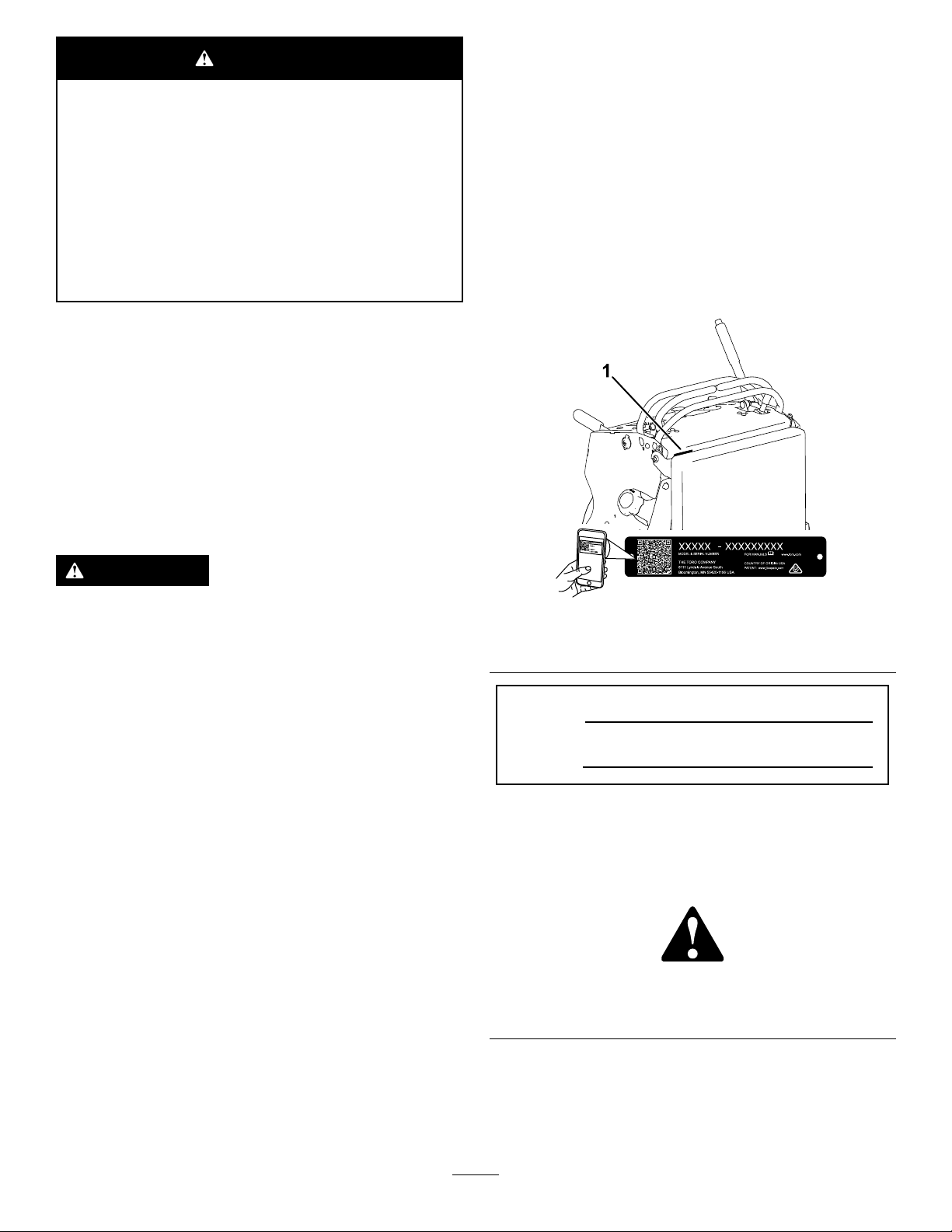
andserialnumbersofyourproductready.Figure1
identiesthelocationofthemodelandserialnumbers
ontheproduct.Writethenumbersinthespace
provided.
Important:Withyourmobiledevice,youcan
scantheQRcodeontheserialnumberdecal(if
equipped)toaccesswarranty,parts,andother
productinformation.
WARNING
Removingstandardoriginalequipmentparts
andaccessoriesmayalterthewarranty,
traction,andsafetyofthemachine.Failureto
useoriginalT oropartscouldcauseserious
injuryordeath.Makingunauthorizedchanges
totheengine,fuelorventingsystem,may
violateEPAandCARBregulations.
Replaceallpartsincluding,butnotlimited
to,tires,belts,blades,andfuelsystem
componentswithoriginalToroparts.
Introduction
Thissnowmachineisintendedtobeused
byprofessional,hiredoperatorsorresidential
homeowners.Itisdesignedtooperateattachmentsto
clearsnowonresidentialorcommercialproperties.
Readthisinformationcarefullytolearnhowtooperate
andmaintainyourproductproperlyandtoavoid
injuryandproductdamage.Youareresponsiblefor
operatingtheproductproperlyandsafely .
YoumaycontactTorodirectlyatwww.Toro.com
forproductsafetyandoperationtrainingmaterials,
g235457
Figure1
1.Locationofthemodelandserialnumbers
ModelNo.
SerialNo.
Thismanualidentiespotentialhazardsandhas
safetymessagesidentiedbythesafety-alertsymbol
(Figure2),whichsignalsahazardthatmaycause
seriousinjuryordeathifyoudonotfollowthe
recommendedprecautions.
g000502
Figure2
1.Safety-alertsymbol
Thismanualuses2wordstohighlightinformation.
Importantcallsattentiontospecialmechanical
informationandNoteemphasizesgeneralinformation
worthyofspecialattention.
©2017—TheToro®Company
8111LyndaleAvenueSouth
Bloomington,MN55420
Contactusatwww.Toro.com.
2
PrintedintheUSA
AllRightsReserved

Contents
Safety.......................................................................4
GeneralSafety...................................................4
SlopeIndicator...................................................5
SafetyandInstructionalDecals..........................6
ProductOverview.....................................................9
Controls.............................................................9
Specications..................................................10
Attachments/Accessories.................................10
BeforeOperation..................................................11
BeforeOperationSafety....................................11
AddingFuel.......................................................11
CheckingtheEngine-OilLevel..........................13
BreakinginaNewMachine..............................13
ThinkSafetyFirst..............................................13
UsingtheSafety-InterlockSystem....................13
DuringOperation.................................................15
DuringOperationSafety...................................15
OperatingtheParkingBrake.............................15
OperatingthePower-T akeoff(PTO)
Switch...........................................................16
OperatingtheThrottle.......................................16
OperatingtheIgnitionSwitch............................16
StartingtheEngine...........................................17
ShuttingOfftheEngine.....................................17
OperatingthePlatform......................................18
DrivingForwardorBackward............................18
StoppingtheMachine.......................................20
UsingWeights..................................................20
AfterOperation....................................................20
AfterOperationSafety......................................20
PreventingFreeze-upafterUse........................20
UsingtheFuel-ShutoffValve.............................21
PushingtheMachinebyHand..........................21
TransportingtheMachine.................................22
LoadingtheMachine........................................22
Maintenance...........................................................24
RecommendedMaintenanceSchedule(s)...........24
Pre-MaintenanceProcedures..............................25
MaintenanceandStorageSafety......................25
ReleasingtheCushionforRearAccess............25
Lubrication..........................................................26
GreasingtheAccessoryFrame.........................26
GreasingtheFrontCasterPivots......................26
GreasingtheCaster-WheelHubs.....................26
GreasingtheVoltageRegulator........................27
GreasingtheBrakeCalipers.............................27
GreasingtheMotionControls...........................28
EngineMaintenance...........................................28
EngineSafety...................................................28
ServicingtheAirCleaner..................................28
ServicingtheEngineOil....................................30
ServicingtheSparkPlug...................................33
CheckingtheSparkArrester.............................34
FuelSystemMaintenance...................................35
DrainingtheFuelT ank......................................35
RemovingtheFuelT ank...................................35
ServicingtheFuelFilter...................................36
ElectricalSystemMaintenance...........................36
ElectricalSystemSafety...................................36
ServicingtheBattery.........................................36
ServicingtheFuses..........................................38
DriveSystemMaintenance..................................39
AdjustingtheTracking......................................39
CheckingtheTirePressure...............................39
AdjustingtheCaster-PivotBearing...................40
ServicingtheCasterWheelsand
Bearings........................................................40
CheckingtheWheel-LugNuts..........................41
CheckingtheWheel-HubNuts..........................41
CoolingSystemMaintenance..............................41
CleaningtheAir-IntakeScreen.........................41
CleaningtheCoolingSystem............................41
BrakeMaintenance.............................................42
ServicingtheBrake..........................................42
BeltMaintenance................................................42
ReplacingtheTransmissionBelt......................42
ControlsSystemMaintenance.............................43
AdjustingtheMotion-ControlLevers.................43
HydraulicSystemMaintenance...........................44
HydraulicSystemSafety...................................44
HydraulicSystemSpecications.......................44
CheckingtheHydraulicFluid............................44
ReplacingtheHydraulicFluidand
Filters............................................................45
BleedingtheHydraulicSystem.........................46
Cleaning..............................................................47
DisposingoftheWaste.....................................47
Storage...................................................................47
CleaningandStorage.......................................47
Troubleshooting......................................................49
Schematics.............................................................51
3

Safety
Thefollowinginstructionshavebeenadaptedfrom
theANSIandISOstandards.
GeneralSafety
Alwaysfollowallsafetyinstructionstoavoidserious
personalinjury.
Usingthisproductforpurposesotherthanitsintended
usecouldprovedangeroustoyouandbystanders.
•Readandunderstandthecontentsofthis
Operator’sManualbeforestartingtheengine.
•Donotputyourhandsorfeetnearmoving
componentsofthemachine.
•Donotoperatethemachinewithoutallguards
andothersafetyprotectivedevicesinplaceand
workingonthemachine.
•Keepclearofanydischargeopening.Keep
bystandersasafedistanceawayfromthe
machine.
•Keepchildrenoutoftheoperatingarea.Never
allowchildrentooperatethemachine.
•Stopthemachineandshutofftheenginebefore
servicing,fueling,oruncloggingthemachine.
Improperlyusingormaintainingthismachinecan
resultininjury .Toreducethepotentialforinjury,
complywiththesesafetyinstructionsandalwayspay
attentiontothesafety-alertsymbol,whichmeans
Caution,Warning,orDanger—personalsafety
instruction.Failuretocomplywiththeseinstructions
mayresultinpersonalinjuryordeath.
Youcanndadditionalsafetyinformationwhere
neededthroughoutthisOperator’sManual.
4
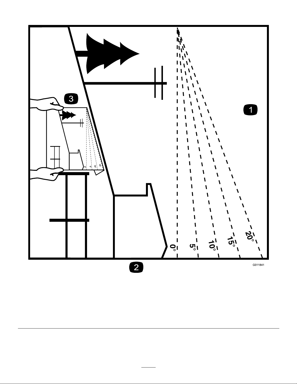
SlopeIndicator
Figure3
Thispagemaybecopiedforpersonaluse.
1.Themaximumslopeyoucanoperatethemachineonis15degrees.Usetheslopecharttodeterminethedegreeofslopeof
hillsbeforeoperating.Donotoperatethismachineonaslopegreaterthan15degrees.Foldalongtheappropriateline
tomatchtherecommendedslope.
2.Alignthisedgewithaverticalsurface,atree,building,fencepole,etc.
3.Exampleofhowtocompareslopewithfoldededge
5
g011841
SafetyandInstructionalDecals
131-3528
15A 15A 10A
7.5A
Safetydecalsandinstructionsareeasilyvisibletotheoperatorandarelocatednearanyarea
ofpotentialdanger.Replaceanydecalthatisdamagedormissing.
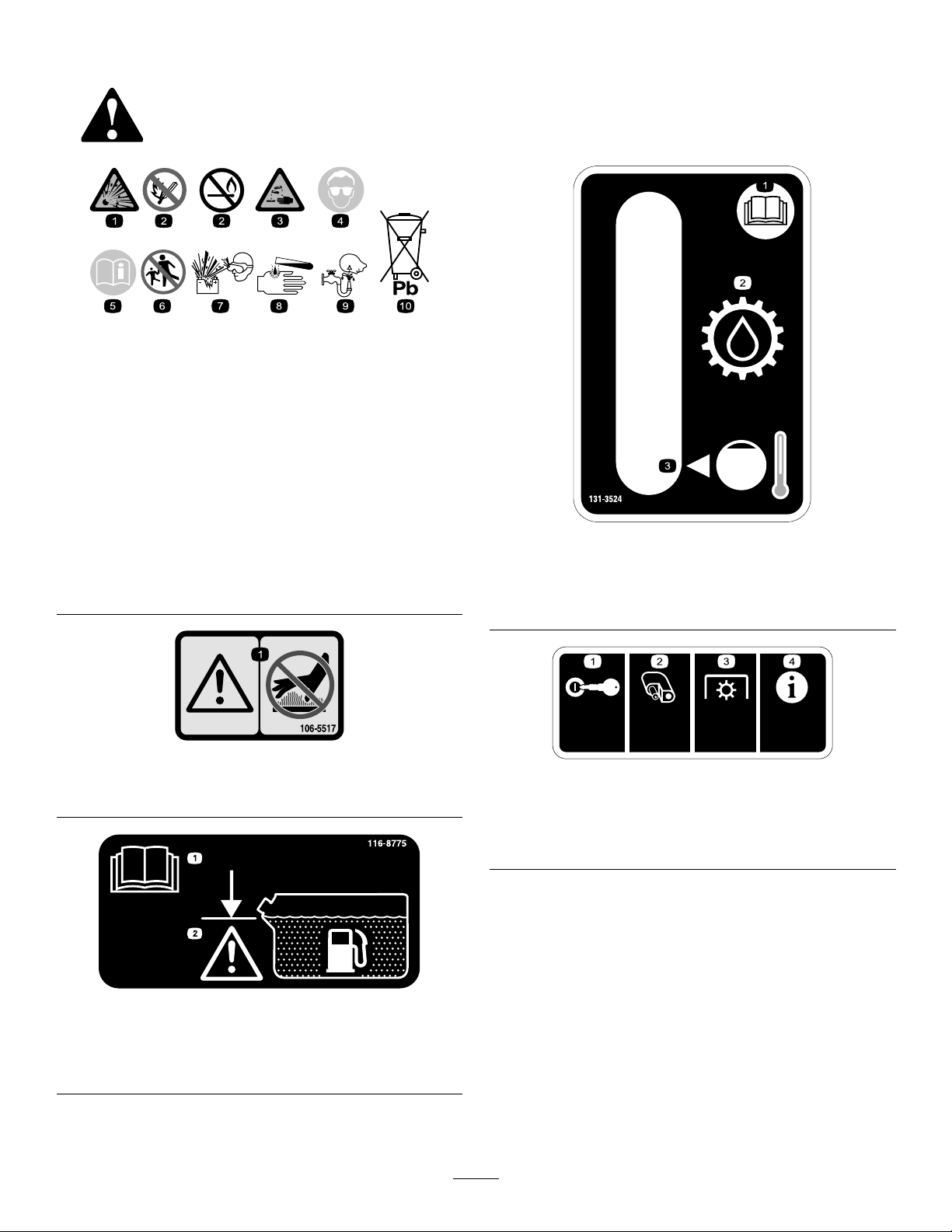
BatterySymbols
Someorallofthesesymbolsareonyourbattery
decalbatterysymbols
1.Explosionhazard
2.Nore,opename,or
smoking.
3.Causticliquid/chemical
burnhazard
4.Weareyeprotection9.Flusheyesimmediately
5.ReadtheOperator's
Manual.
6.Keepbystandersasafe
7.Weareyeprotection;
8.Batteryacidcancause
10.Containslead;donot
106-5517
1.Warning—donottouchthehotsurface.
distancefromthebattery.
explosivegasescan
causeblindnessandother
injuries
blindnessorsevereburns.
withwaterandgetmedical
helpfast.
discard.
decal106-5517
1.ReadtheOperator's
Manual.
2.Transmissionoil
1.Ingition—15A
2.Accessoryport—15A
decal131-3524
131-3524
3.Oillevel
decal131-3528
131-3528
3.Powertakeoff(PTO)—10
A
4.Infocenter—7.5A
1.ReadtheOperator’s
Manual.
116-8775
decal116-8775
2.Filltobottomofllerneck;
warning—donotoverll
thetank.
6
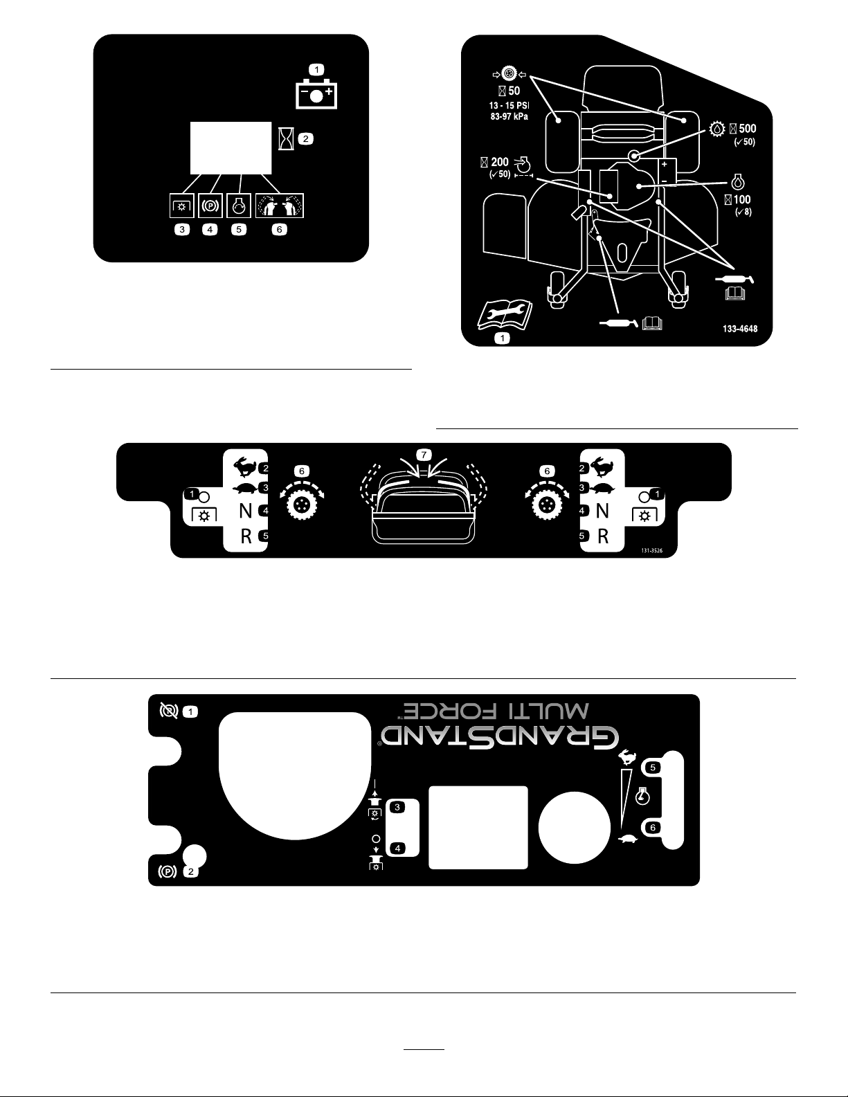
131-3536
1.Battery4.Parkingbrake
2.Time5.Engine—start
3.Powertakeoff(PTO)
6.Engagethehandlebars.
decal131-3536
decal133-4648
133-4648
1.ReadtheOperator'sManualformoreinformationon
servicingthemachine.
decal131-3526
131-3526
1.Powertakeoff(PTO)—disengaged
5.Reverse
2.Fast6.Tractiondrive
3.Slow
7.Engagethehandles.
4.Neutral
133-1432
1.Disengagetheparkingbrake.
2.Engagetheparkingbrake.
3.PulluptoturnonthePTO.
4.PushdowntoturnoffthePTO.
5.Enginespeed—fast
6.Enginespeed—slow
decal133-1432
7

decal136-5438
136-5438
1.Warning—readtheOperator'sManual.6.Thrownobjecthazard—keepbystandersawayfromthe
machine.
2.Warning—receivetrainingbeforeoperatingthemachine.
7.Warning—engagetheparkingbrake,stoptheengine,and
removethekeyfromtheignitionbeforeleavingthemachine.
3.Warning—hearingprotectionmustbeworn.8.Ramphazard—donotusedualrampswhenloadingontoa
trailer;use1rampwideenoughforthemachine;usearamp
withaslopelessthan15°;backuptherampwhenloadingthe
machineanddriveforwardofftherampwhenunloading.
4.Thrownobjecthazard—keepthedeectorloweredduring
9.Tippinghazard—donotoperateneardrop-offsornearwater.
operation.
5.Cutting/severinghazardofhandorfoot—keepawayfrom
movingparts;keepallguardsandshieldsinplace.
8
ProductOverview
Controls
Becomefamiliarwithallthecontrolsbeforeyoustart
theengineandoperatethemachine(Figure5).
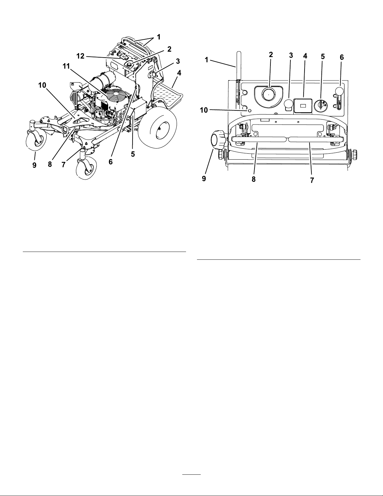
Figure4
1.Controllevers
2.Hydraulictank
3.Fueltank9.Frontcasterwheel
4.Platform(downposition)10.Accessoryframe
5.Battery11.Engine
6.Fuel-shutoffvalve12.Controls
7.Adjustablecaster
8.Accessory-framelock
g192638
Figure5
1.Parking-brakelever
2.Hydraulic-tankcap7.Rightmotion-controllever
3.Power-takeoff(PTO)
switch
4.Hourmeter9.Fuelcap
5.Ignitionswitch
6.Throttlecontrol
8.Leftmotion-controllever
10.Malfunction-indicatorlight
(MIL)
g192637
HourMeter
Thehourmeterrecordsthenumberofhoursthe
enginehasoperated.Itoperateswhentheengine
isrunning.Usethesetimesforschedulingregular
maintenance(Figure5).
Safety-InterlockIndicators
Therearesymbolsonthehourmeterthatindicate
withablacktrianglethattheinterlockcomponentis
positionedcorrectly(Figure5).
Battery-IndicatorLight
IftheignitionkeyisturnedtotheONpositionfora
fewseconds,thebatteryvoltagedisplaysinthearea
wherethehoursarenormallydisplayed.
Thebatterylightturnsonwhentheignitionisturned
onandwhenthechargeisbelowthecorrectoperating
level(Figure5).
9
ThrottleControl
AdjustableCasters
Thethrottlecontrolstheenginespeed,andithasa
continuous-variablesettingfromtheSLOWtoFAST
position(Figure5).
Power-Takeoff(PTO)switch
Usethepower-takeoff(PTO)switchtostartandstop
poweredattachments(Figure5).
IgnitionSwitch
Usethisswitchtostarttheengine.Ithas3positions:
START,RUN,andOFF.
Motion-ControlLevers
Usethemotion-controlleverstodrivethemachine
forward,reverse,andturneitherdirection.
Fuel-ShutoffValve
Closethefuel-shutoffvalve(locatedontheleftside
ofthefueltank)whentransportingorstoringthe
machine(Figure4).
Whenusingthemachinewithanattachment,refer
totheOperator’sManualforthatattachmentforthe
correctcasterposition(Figure6).Donotoperatethe
machinewithoutanattachmentinstalledonthefront
ofthemachine.
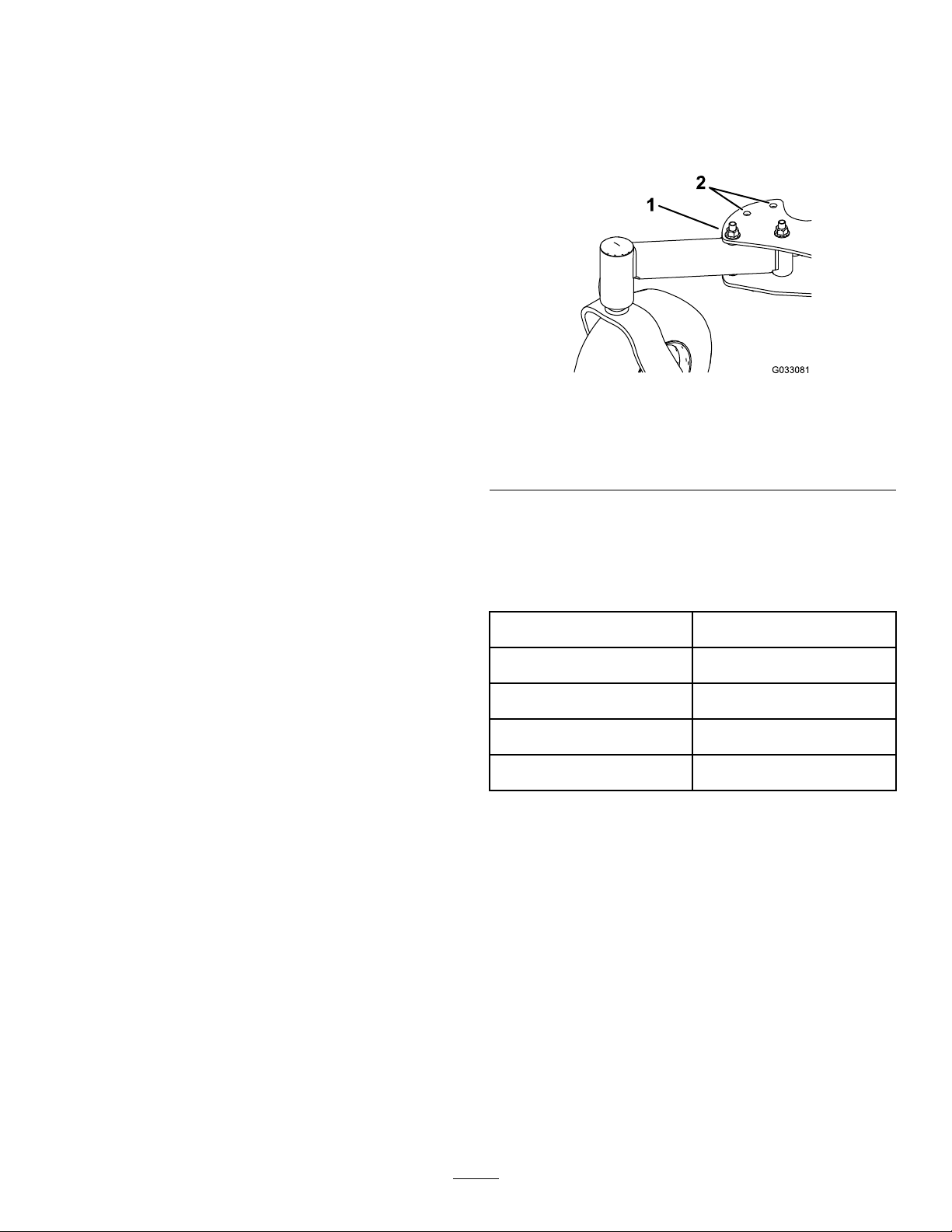
Figure6
RightCasterShown
1.Casterboltandnutinfront
casterhole
2.Casterholes
Specications
g033081
AccessoryFrame
UsetheaccessoryframetoattachonlyToro-approved
accessoriestothemachine(Figure4).Refertothe
Operator’sManualfortheaccessoryforinstallation
instructions.
Accessory-FrameLock
Theaccessory-framelockholdstheframeinplaceon
themachineusingthelockpin.Alwayslocktheframe
unlessahydraulickitisinstalledwithanaccessory
onthemachine(Figure4).
Electronic-ControlUnit
Malfunction-IndicatorLight
Theelectronic-controlunit(ECU)continuously
monitorstheoperationoftheEFIsystem.
Ifaproblemorfaultwithinthesystemisdetected,the
malfunction-indicatorlight(MIL)isilluminated(Figure
5).
TheMIListheredlightlocatedintheconsolepanel.
WhentheMILilluminates,makeinitialtroubleshooting
checks.
Ifthesechecksdonotcorrecttheproblem,further
diagnosisandservicingbyanAuthorizedService
Dealerisnecessary.
Note:Specicationsanddesignaresubjectto
changewithoutnotice.
Width
Lengthwithplatformdown191cm(75inches)
Lengthwithplatformup155cm(61inches)
Height
Weight
122cm(48inches)
122cm(48inches)
308kg(680lb)
Attachments/Accessories
AselectionofToroapprovedattachmentsand
accessoriesisavailableforusewiththemachineto
enhanceandexpanditscapabilities.Contactyour
AuthorizedServiceDealerorDistributororgoto
www.T oro.comforalistofallapprovedattachments
andaccessories.
Tobestprotectyourinvestmentandmaintainoptimal
performanceofyourToroequipment,countonT oro
genuineparts.Whenitcomestoreliability ,Toro
deliversreplacementpartsdesignedtotheexact
engineeringspecicationofourequipment.Forpeace
ofmind,insistonTorogenuineparts.
10

Operation
possible,thenrefuelfromaportablecontainer
ratherthanafuel-dispensernozzle.
Note:Determinetheleftandrightsidesofthe
machinefromthenormaloperatingposition.
BeforeOperation
BeforeOperationSafety
GeneralSafety
•Neverallowchildrenoruntrainedpeopleto
operateorservicethemachine.Localregulations
mayrestricttheageoftheoperator.Theowner
isresponsiblefortrainingalloperatorsand
mechanics.
•Becomefamiliarwiththesafeoperationofthe
equipment,operatorcontrols,andsafetysigns.
•Knowhowtostopthemachineandshutoffthe
enginequickly.
•Checkthatoperator-presencecontrols,safety
switches,andshieldsareattachedandfunctioning
properly.Donotoperatethemachineunlessthey
arefunctioningproperly.
•Evaluatetheterraintodeterminetheappropriate
equipmentandanyattachmentsoraccessories
requiredtooperatethemachineproperlyand
safely.
•Donotoperatethemachinewithoutanattachment
installedonthefrontofthemachine.
•Donotoperatethemachinewithouttheentire
exhaustsysteminplaceandinproperworking
condition.
•Keepthefuel-dispensernozzleincontactwith
therimofthefueltankorcontaineropeningat
alltimesuntilfuelingiscomplete.Donotusea
nozzlelock-opendevice.
•Ifyouspillfuelonyourclothing,changeyour
clothingimmediately.Wipeupanyfuelthatspills.
•Neveroverllthefueltank.Replacethefuelcap
andtightenitsecurely.
•Storefuelinanapprovedcontainerandkeepit
outofthereachofchildren.Neverbuymorethan
a30-daysupplyoffuel.
•Donotllthefueltankcompletelyfull.Addfuelto
thefueltankuntilthelevelis6to13mm(1/4to
1/2inch)belowthebottomofthellerneck.This
emptyspaceinthetankallowsfueltoexpand.
–Avoidprolongedbreathingofvapors.
–Keepyourfaceawayfromthenozzleandfuel
tankopening.
–Avoidcontactwithskin;washoffspillswith
soapandwater.
AddingFuel
•Forbestresults,useonlyclean,fresh(lessthan
30daysold),unleadedgasolinewithanoctane
ratingof87orhigher((R+M)/2ratingmethod).
FuelSafety
•Toavoidpersonalinjuryorpropertydamage,use
extremecareinhandlingfuel.Fuelvaporsare
ammableandexplosive.
•Extinguishallcigarettes,cigars,pipes,andother
sourcesofignition.
•Useonlyanapprovedfuelcontainer.
•Donotremovethefuelcaporaddfueltothefuel
tankwhiletheengineisrunningorwhilehot.
•Donotrefuelthemachineindoors.
•Donotstorethemachineorfuelcontainerwhere
thereisanopename,spark,orpilotlight,such
asonawaterheateroronotherappliances.
•Donotllcontainersinsideavehicleoronatruck
ortrailerbedwithaplasticliner.Alwaysplace
containersontheground,awayfromyourvehicle
beforelling.
•Removetheequipmentfromthetruckortrailer
andrefuelitwhileitisontheground.Ifthisisnot
•Ethanol:Gasolinewithupto10%ethanol
(gasohol)or15%MTBE(methyltertiarybutyl
ether)byvolumeisacceptable.Ethanoland
MTBEarenotthesame.Gasolinewith15%
ethanol(E15)byvolumeisnotapprovedforuse.
Neverusegasolinethatcontainsmorethan
10%ethanolbyvolume,suchasE15(contains
15%ethanol),E20(contains20%ethanol),orE85
(containsupto85%ethanol).Usingunapproved
gasolinemaycauseperformanceproblemsand/or
enginedamagethatmaynotbecoveredunder
warranty.
•Donotusegasolinecontainingmethanol.
•Donotstorefueleitherinthefueltankorfuel
containersoverthewinterunlessyouuseafuel
stabilizer.
•Donotaddoiltogasoline.
11

DANGER
WARNING
Incertainconditions,fuelisextremely
ammableandhighlyexplosive.Areor
explosionfromfuelcanburnyouandothers
andcandamageproperty.
•Fillthefueltankoutdoors,inanopenarea,
whentheengineiscold.Wipeupanyfuel
thatspills.
•Neverllthefueltankinsideanenclosed
trailer.
•Donotllthefueltankcompletelyfull.
Addfueltothefueltankuntilthelevelis6
to13mm(1/4to1/2inch)belowthebottom
ofthellerneck.Thisemptyspaceinthe
tankallowsfueltoexpand.
•Neversmokewhenhandlingfuel,andstay
awayfromanopenameorwherefuel
fumesmaybeignitedbyaspark.
•Storefuelinanapprovedcontainerand
keepitoutofthereachofchildren.Never
buymorethana30-daysupplyoffuel.
•Donotoperatewithoutentireexhaust
systeminplaceandinproperworking
condition.
Fuelisharmfulorfatalifswallowed.
Long-termexposuretovaporscancause
seriousinjuryandillness.
•Avoidprolongedbreathingofvapors.
•Keepyourfaceawayfromthenozzleand
fueltankorconditionerbottleopening.
•Avoidcontactwithskin;washoffspills
withsoapandwater.
UsingStabilizer/Conditioner
Useafuelstabilizer/conditionerinthemachineto
providethefollowingbenets:
•Keepsfuelfreshduringstorageof90daysorless.
Forlongerstorage,drainthefueltank.
•Cleanstheenginewhileitruns
•Eliminatesgum-likevarnishbuildupinthefuel
system,whichcauseshardstarting
Important:Donotusefueladditives
containingmethanolorethanol.
Addthecorrectamountoffuelstabilizer/conditioner
tothefuel.
DANGER
Incertainconditionsduringfueling,static
electricitycanbereleasedcausingaspark,
whichcanignitethefuelvapors.Areor
explosionfromfuelcanburnyouandothers
andcandamageproperty.
•Alwaysplacefuelcontainersontheground
awayfromyourvehiclebeforelling.
•Donotllfuelcontainersinsideavehicle
oronatruckortrailerbedbecauseinterior
carpetsorplastictruckbedlinersmay
insulatethecontainerandslowthelossof
anystaticcharge.
•Whenpractical,removeequipmentfrom
thetruckortrailerandrefueltheequipment
withitswheelsontheground.
•Ifthisisnotpossible,thenrefuelsuch
equipmentonatruckortrailerfroma
portablecontainerratherthanfroma
fuel-dispensernozzle.
•Ifyoumustuseafuel-dispensernozzle,
keepthenozzleincontactwiththerimof
thefueltankorcontaineropeningatall
timesuntilfuelingiscomplete.
Note:Afuelstabilizer/conditionerismost
effectivewhenmixedwithfreshfuel.T ominimize
thechanceofvarnishdepositsinthefuelsystem,
usefuelstabilizeratalltimes.
FillingtheFuelTank
1.Parkthemachineonalevelsurface,disengage
thePTO,movethemotion-controlleverstothe
NEUTRAL-LOCKposition,andengagetheparking
brake.
2.Shutofftheengine,removethekey,andwait
forallmovingpartstostopbeforeleavingthe
operatingposition.
3.Cleanaroundthefuel-tankcapandremovethe
cap.
4.Fillthefueltanktothebottomofthellerneck.
Note:Donotllthefueltankcompletelyfull.
Theemptyspaceinthetankallowsthefuelto
expand.
5.Installthefuel-tankcapsecurely.Wipeupany
spilledfuel.
12
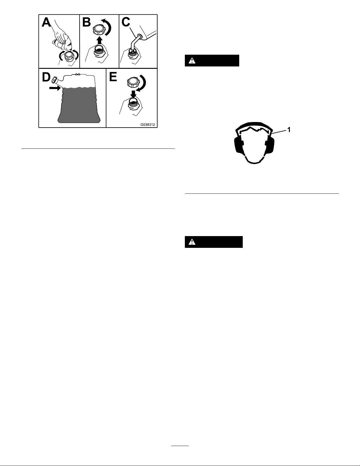
Figure7
ThinkSafetyFirst
Carefullyreadallthesafetyinstructionsanddecals
inthesafetysection.Knowingthisinformationcould
helpyouorbystandersavoidinjury.
CAUTION
Thismachineproducessoundlevelsin
excessof85dBAattheoperator'searand
cancausehearinglossfromextendedperiods
ofexposure.
Wearhearingprotectionwhenoperatingthis
machine.
g038312
CheckingtheEngine-Oil Level
Beforeyoustarttheengineandusethemachine,
checktheoillevelintheenginecrankcase;referto
Maintenance(page24).
BreakinginaNewMachine
Newenginestaketimetodevelopfullpower.Drive
systemshavehigherfrictionwhennew,placing
additionalloadontheengine.Allow40to50hoursof
break-intimefornewmachinestodevelopfullpower
andbestperformance.
g229846
Figure8
1.Wearhearingprotection.
UsingtheSafety-Interlock System
WARNING
Ifsafety-interlockswitchesaredisconnected
ordamaged,themachinecouldoperate
unexpectedlycausingpersonalinjury.
•Donottamperwiththeinterlockswitches.
•Checktheoperationoftheinterlock
switchesdaily,andreplaceanydamaged
switchesbeforeoperatingthemachine.
Understandingthe Safety-InterlockSystem
Thesafety-interlocksystemisdesignedtoprevent
poweringtheattachmentunlessyoudo1ofthe
following:
•Moveeithermotion-controllevertothecenter,
unlockedposition.
•PullthePTOswitchtotheONposition.
Thesafety-interlocksystemisdesignedtostop
theattachmentifyoumoveorreleaseboth
motion-controlleversintotheNEUTRAL-LOCK
position.
Thehourmeterhassymbolstonotifytheuser
wheneachinterlockcomponentisinthecorrect
13
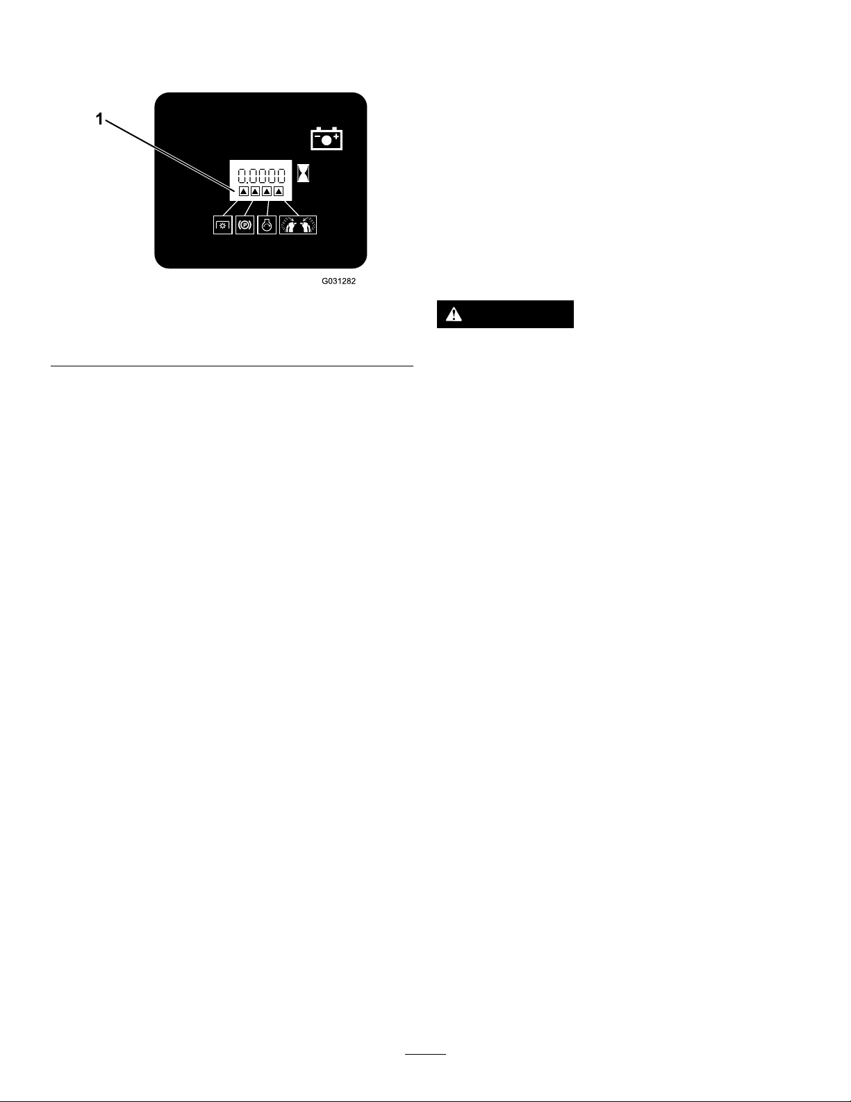
position.Whenthecomponentisinthecorrect
position,atrianglelightsupinthecorresponding
square(Figure9).
8.Continueholdingthemotion-controlleverinthe
center,unlockedposition,pulluponthePTO
switch,andreleasetheswitch.
Note:Theclutchandattachmentshould
engage.
9.PushthePTOswitchdowntotheOFFposition.
Note:Theattachmentshouldstop.
10.Withtheenginerunning,pullupthePTO
switchandreleaseitwithoutholdingeither
motion-controllevertothecenter,unlocked
position.
Figure9
1.Triangleslightupwhentheinterlockcomponentsareinthe
correctposition.
TestingtheSafety-Interlock System
ServiceInterval:Beforeeachuseordaily
Testthesafety-interlocksystembeforeyouusethe
machineeachtime.
Note:Ifthesafetysystemdoesnotoperateas
describedbelow,haveanAuthorizedServiceDealer
repairthesafetysystemimmediately.
1.Starttheengine;refertoStartingtheEngine
(page17).
2.Movethemotion-controlleverstothecenter,
unlockedposition.
Note:Theattachmentshouldstopandthe
engineshouldstoprunning.
g031282
Note:Theattachmentshouldnotengage.
WARNING
Theoperatorplatformisheavyandmaycause
injurywhenyouraiseorlowerit.Carefully
lowerorraisetheoperatorplatform,as
suddenlydroppingitcouldinjureyou.
•Donotputyourhandsorngersinthe
platform-pivotareawhenloweringor
raisingtheoperatorplatform.
•Makesurethattheplatformissupported
whenyoupullthelatchpinout.
•Makesurethatthelatchsecuresthe
platformwhenfoldingitup.Pushittight
againstthecushionforthelatchpinto
lockintoplace.
•Keepbystandersawayfromthemachine
whenraisingorloweringtheplatform.
3.Starttheengineanddisengagetheparking
brake.
4.Moveeithermotion-controllevertothecenter,
unlockedposition.
5.Continueholdingthemotion-controlleverinthe
center,unlockedposition,pulluponthePTO
switch,andreleasetheswitch.
Note:Theclutchandattachmentshould
engage.
6.Moveorreleasethemotion-controlleversinto
theNEUTRAL-LOCKposition.
Note:Theattachmentshouldstopandthe
engineshouldcontinuetorun.
7.PushthePTOswitchdownandmoveeither
motion-controllevertothecenter,unlocked
position.
14
DuringOperation
DuringOperationSafety
–Waitforallmovingpartstostop.
•Donotoperatethemachinewhenthereistherisk
oflightning.
•Donotusethemachineasatowingvehicle.
GeneralSafety
•Theowner/operatorcanpreventandisresponsible
foraccidentsthatmaycausepersonalinjuryor
propertydamage.
•Wearappropriateclothing,includingadequate
wintergarmentseyeprotection;slip-resistant,
substantialfootwearthatwillimprovefootingon
slipperysurfaces;andhearingprotection.Tieback
longhairanddonotwearjewelry.
•Donotoperatethemachinewhileill,tired,or
undertheinuenceofalcoholordrugs.
•Nevercarrypassengersonthemachineandkeep
bystandersandpetsawayfromthemachine
duringoperation.
•Operatethemachineonlyingoodvisibilitytoavoid
holesorhiddenhazards.
•Ensurethatalldrivesareinneutral,theparking
brakeisengaged,andyouareintheoperating
positionbeforeyoustarttheengine.
•Lookbehindanddownbeforebackinguptobe
sureofaclearpath.
•Usecarewhenapproachingblindcorners,shrubs,
trees,orotherobjectsthatmayobscureyour
vision.
•Donotusethemachineneardrop-offs,ditches,or
embankments.Themachinecouldsuddenlyroll
overifawheelgoesovertheedgeoriftheedge
givesway.
•Stopandinspectthemachineafterstrikingan
objectorifthereisanabnormalvibrationinthe
machine.Makeallnecessaryrepairsbefore
resumingoperation.
•Donotchangethegovernorspeedoroverspeed
theengine.
•Useaccessoriesandattachmentsapprovedby
Toroonly .
SlopeSafety
•Slowdownthemachineanduseextracareon
hillsides.Travelupanddownonhillsides.Turf
conditionscanaffectthestabilityofthemachine.
•Avoidturningthemachineonslopes.Ifyoumust
turnthemachine,turnitslowlyandgradually
downhill,ifpossible.
•Donotturnthemachinesharply.Usecarewhen
reversingthemachine.
•Useextracarewhileoperatingthemachinewith
attachments;theycanaffectthestabilityofthe
machine.
OperatingtheParking Brake
Alwaysengagetheparkingbrakewhenyoushutoff
themachineorleaveitunattended.Beforeeachuse,
checktheparkingbrakeforproperoperation.
Iftheparkingbrakedoesnotholdsecurely,adjustit;
refertoAdjustingtheBrakes(page42).
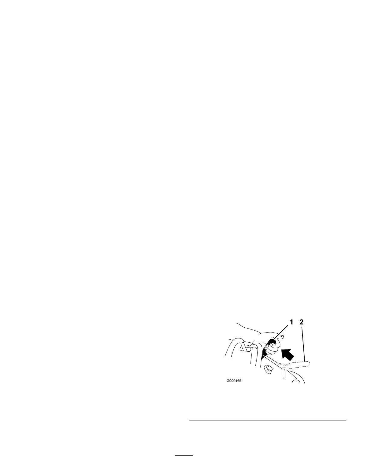
Pulltheparking-brakeleverrearwardtoengageit
(Figure10).
Pushtheparking-brakeleverforwardtodisengageit.
•Slowdownandusecautionwhenmakingturns
andcrossingroadsandsidewalkswiththe
machine.Alwaysyieldtheright-of-way.
•Neverrunanengineinanareawhereexhaust
gasesareenclosed.
•Neverleavearunningmachineunattended.
•Beforeleavingtheoperatingposition,dothe
following:
–Stopthemachineonlevelground.
–Disengagethepowertake-offandlowerthe
attachments.
–Engagetheparkingbrake.
–Shutofftheengineandremovethekey.
g009465
Figure10
1.Parkingbrake—engaged2.Parking
brake—disengaged
15
Operatingthe
OperatingtheThrottle
Power-Takeoff(PTO)
Switch
Thepower-takeoff(PTO)switchstartsandstopsany
poweredattachments.
EngagingthePower-Takeoff(PTO) Switch
Note:Engagingthepower-takeoff(PTO)switchwith
thethrottlepositionathalforlesscausesexcessive
weartothedrivebelts.
Figure11
DisengagingthePower-Takeoff
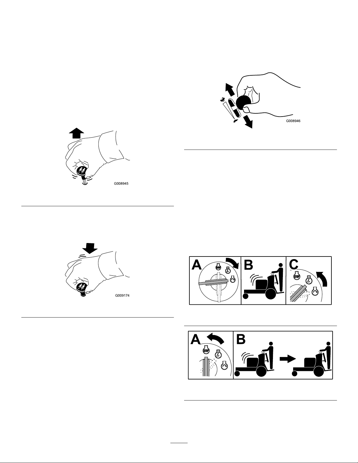
YoucanmovethethrottlecontrolbetweentheFAST
andSLOWpositions(Figure13).
AlwaysusetheFASTpositionwhenturningon
poweredattachmentswiththepower-takeoff(PTO)
switch.
g008946
Figure13
OperatingtheIgnition
g008945
Switch
Important:Donotengagethestarterformore
than5secondsatatime.Iftheenginefailsto
start,wait15secondsbetweenattempts.Failure
tofollowtheseinstructionscanburnoutthe
startermotor.
(PTO)Switch
g009174
Figure12
Note:Youmayneedtorepeatthecycleforstarting
theenginewhenyoustartitforthersttimeafteryou
havelledacompletelyemptyfuelsystemwithfuel.
g192743
Figure14
g192744
Figure15
16

StartingtheEngine
Important:Donotengagethestarterformore
than5secondsatatime.Iftheenginefailsto
start,wait15secondsbetweenattempts.Failure
tofollowtheseinstructionscanburnoutthe
startermotor.
Note:Youmayneedtorepeatthecycleforstarting
theenginewhenyoustartitforthersttimeafteryou
havelledacompletelyemptyfuelsystemwithfuel.
ShuttingOfftheEngine
CAUTION
Childrenorbystandersmaybeinjuredifthey
moveorattempttooperatethemachinewhile
itisunattended.
Alwaysremovethekeyandengagethe
parkingbrakewhenleavingthemachine
unattended.
Lettheengineidleatslowthrottle(turtle)for60
secondsbeforeturningthekeyswitchtotheOFF
position.
Figure16
g192745
g030982
Figure17
Important:Makesurethatthefuel-shutoffvalve
isclosedbeforetransportingorstoringthe
machinetopreventafuelleak.Beforestoringthe
machine,disconnectthesparkplug(s)toprevent
thepossibilityofaccidentalstarting.
17

OperatingthePlatform
Youcanusethemachinewiththeplatforminthe
upordownposition.Itisyourpreferenceonwhich
positiontouse.
OperatingtheMachinewiththe PlatformUp
Operatethemachinewiththeplatformupforthe
followingconditions:
•Usingthemachineneardrop-offs
•Usingthemachineinsmallareaswherethe
machineistoolarge
•Areaswithlow-hangingbranchesorobstacles
•Loadingthemachinefortransport
•Drivingupslopes
Toraisetheplatform,pullthebackoftheplatformup
sothatthelatchpinandknoblockitintoplace.Push
ittightagainstthecushionforthelatchpintolockit
intoplace.
1.Platformup
2.Platformdown
g192759
Figure18
3.Pulltheknobouttorelease
theplatform.
OperatingtheMachinewiththe PlatformDown
Operatethemachinewiththeplatformdownforthe
followingconditions:
•Usingthemachineinmostareas
•Drivingacrossslopes
•Drivingdownslopes
Tolowertheplatform,pushtheplatformforward
againstthecushiontoreleasepressureonthelatch
pin,thenpulltheknoboutandlowertheplatform
(Figure18).
DrivingForwardor Backward
Thethrottlecontrolregulatestheenginespeedas
measuredinrpm(revolutionsperminute).Place
thethrottlecontrolintheFASTpositionforbest
performance.
Important:Backthemachineovercurbs,1wheel
atatime;drivingitforwardovercurbscould
damagethemachine.
CAUTION
Themachinecanspinveryrapidly,andyou
maylosecontrolofthemachine,causing
personalinjurytoyouanddamagetothe
machine.
Slowdownthemachinebeforemakingsharp
turns.
18

DrivingForward
1.Disengagetheparkingbrake;refertoOperating
theParkingBrake(page15).
2.Movethemotion-controlleverstothecenter,
unlockedposition.
g192742
Figure20
Figure19
1.Frontreferencebar
2.Leftcontrollever
3.Rearreferencebar6.Leftcontrolleverinthe
4.Rightcontrollever
5.Rightcontrolleverinthe
NEUTRAL-LOCKposition
NEUTRAL-LOCKposition
3.Slowlypushthemotion-controlleversforward
(Figure20).
Note:Theengineshutsoffifyoumovea
motion-controlleverwhiletheparkingbrakeis
engaged.
Note:Thefartheryoumovethemotion-control
leversineitherdirection,thefasterthemachine
movesinthatdirection.
Note:Tostop,pullthemotion-controllevers
backtotheNEUTRALposition.
g030983
DrivingBackward
1.Movebothmotion-controlleverstothecenter,
unlockedposition.
2.Slowlypullthemotion-controlleversrearward
(Figure21).
g192741
Figure21
19

StoppingtheMachine
Tostopthemachine,movethemotion-controllevers
toneutral,andthenmovethemtotheNEUTRAL-LOCK
position,disengagethepowertakeoff(PTO),andturn
theignitionkeytotheOFFposition.
Engagetheparkingbrakewhenyouleavethe
machine;refertoOperatingtheParkingBrake(page
15).
Note:Remembertoremovethekeyfromtheignition
switch.
CAUTION
Childrenorbystandersmaybeinjuredifthey
moveorattempttooperatethemachinewhile
itisunattended.
AfterOperation
AfterOperationSafety
GeneralSafety
•Cleansnowanddebrisfromthedrives,mufers,
andenginecompartmenttohelppreventres.
Cleanupoilorfuelspills.
•Shutoffthefuelbeforestoringortransportingthe
machine.
•Disengagethedrivetotheattachmentwhenever
youaretransportingornotusingthemachine.
•Usefull-widthrampsforloadingthemachineinto
atrailerortruck.
Alwaysremovetheignitionkeyandengage
theparkingbrakewhenleavingthemachine
unattended,evenifjustforafewminutes.
UsingWeights
•Installweightstoimprovebalance.Youcanaddor
removeweightstocreateoptimizedperformance
underdifferentoperatingconditionsandforyour
preference.
•Addorremoveweights1atatimeuntilyou
achievethedesiredhandlingandbalance.
•RefertotheOperator’sManualofattachmentsfor
recommendedweights.
Note:ContactanAuthorizedServiceDealertoorder
aweightkit.
WARNING
Excessiveweightchangescanaffectthe
handlingandoperationofthemachine.
Thiscouldcauseseriousinjurytoyouor
bystanders.
•Makeweightchangesinsmallincrements
only.
•Evaluatethemachineaftereachweight
changetoensurethatyoucanoperatethe
machinesafely .
•Tiethemachinedownsecurelyusingstraps,
chains,cable,orropes.Bothfrontandrearstraps
shouldbedirecteddownandoutwardfromthe
machine.
•Allowtheenginetocoolbeforestoringthemachine
inanyenclosure.
•Shutoffthefuelbeforestoringortransportingthe
machine.
•Neverstorethemachineorfuelcontainerwhere
thereisanopename,spark,orpilotlight,such
asonawaterheateroronotherappliances.
PreventingFreeze-upafter Use
•Insnowyandcoldconditions,somecontrolsand
movingpartsmayfreeze.Donotuseexcessive
forcewhentryingtooperatefrozencontrols.
Ifyouhavedifcultyoperatinganycontrolorpart,
starttheengineandletitrunforafewminutes.
Thawfrozenpartsbeforeoperatingthemachine.
•Afterusingthemachine,lettheenginerunfora
fewminutestopreventmovingpartsfromfreezing.
Shutofftheengine,waitforallmovingparts
tostop,andremovealliceandsnowfromthe
machine.
20

UsingtheFuel-Shutoff
PushingtheMachineby
Valve
Closethefuel-shutoffvalvefortransport,maintenance,
andstorage(Figure22).
Ensurethatthefuel-shutoffvalveisopenwhen
startingtheengine.
Hand
Thebypassvalvesallowyoutopushthemachineby
handwithouttheenginerunning.
Important:Alwayspushthemachinebyhand.
Donottowthemachine,becausehydraulic
damagemayoccur.
Important:Donotstartoroperatethemachine
withthebypassvalvesopen.Damagetosystem
mayoccur.
g192837
Figure22
1.ONposition2.OFFposition
g031238
g192836
Figure23
21

TransportingtheMachine
LoadingtheMachine
Useaheavy-dutytrailerortrucktotransportthe
machine.Ensurethatthetrailerortruckhasall
thenecessarybrakes,lighting,andmarkingas
requiredbylaw.Pleasecarefullyreadallthesafety
instructions.
1.Raisetheplatformofthemachinebeforedriving
ontothetrailerortruck.
2.Ifusingatrailer,connectittothetowingvehicle
andconnectthesafetychains.
3.Ifapplicable,connectthetrailerbrakes.
4.Loadthemachineontothetrailerortruck.
5.Shutofftheengine,removethekey,setthe
brake,andclosethefuelvalve.
6.Usethemetaltie-downloopsandthe
caster-wheelframestosecurelyfastenthe
machinetothetrailerortruckwithstraps,
chains,cable,orropes(Figure24).
Useextremecautionwhenloadingorunloadingthe
machineontoatraileroratruck.Useafull-widthramp
thatiswiderthanthemachineforthisprocedure.
Backthemachineuptherampandwalkitforward
downtheramp(Figure25).
Figure25
1.Backthemachineupthe
ramp.
2.Walkthemachinedown
theramp.
Important:Donotusenarrowindividualramps
foreachsideofthemachine.
WARNING
Loadingamachineontoatrailerortruck
increasesthepossibilityoftip-overandcould
causeseriousinjuryordeath(Figure26).
g192838
1.Tractionunittie-downloop
Figure24
2.Caster-wheelframe
•Useextremecautionwhenoperatinga
machineonaramp.
•Useonlyafull-widthramp;donotuse
individualrampsforeachsideofthe
machine.
•Donotexceeda15-degreeanglebetween
g192839
therampandthegroundorbetweenthe
rampandthetrailerortruck.
•Ensurethatthelengthoframpisatleast
4timesaslongastheheightofthetrailer
ortruckbedtotheground.Thisensures
thattherampangledoesnotexceed15
degreesonatground.
•Backuprampsanddriveforwarddown
ramps.
•Avoidsuddenaccelerationordeceleration
whiledrivingthemachineonarampas
thiscouldcausealossofcontrolora
tip-oversituation.
22

Figure26
g027996
1.Full-widthrampinstowed
position
2.Sideviewoffull-width
rampinloadingposition
3.Notgreaterthan
15degrees
4.Therampisatleast4
timesaslongastheheight
ofthetrailerortruckbed
totheground
5.H=heightofthetraileror
truckbedtotheground
6.Trailer
23

Maintenance
Note:Determinetheleftandrightsidesofthemachinefromthenormaloperatingposition.
RecommendedMaintenanceSchedule(s)
MaintenanceService
Interval
Aftertherst8hours
Aftertherst50hours
Aftertherst100hours
Beforeeachuseordaily
Every50hours
Every100hours
Every150hours
Every200hours
Every300hours
MaintenanceProcedure
•Changetheengineoil.
•Checkthehydraulic-uidlevel.
•Changethehydraulicltersandhydraulicuid.
•Checkthewheel-lugnuts.
•Checkthewheel-hubnuts.
•Checkthesafety-interlocksystem.
•Checktheengine-oillevel.
•Cleantheair-intakescreen.
•Checkthebrakes.
•Checkthesparkarrester(ifequipped).
•Checkthetirepressure.
•Changetheengineoil.
•Checkthebattery.
•Checkandcleantheenginecoolingnsandshrouds.
•Inspecttheprimarylterandtheair-inletscreen.
•Changetheengine-oillter.
•Check,cleanandgapthesparkplug.
•Replacetheprimaryairlter(moreoftenindustyorsandyconditions).
•Checktheinnerairlter.
•Adjustthecaster-pivotbearing.
Every500hours
Every600hours
Every800hours
Every1,000hours
Beforestorage
Yearly
•Checkthewheel-hubnuts.
•Checkthehydraulic-uidlevel.
•Changethehydraulicltersandhydraulicuid.
•Replacetheinnerairlter.
•Replacethefuellter .
•Replacethetransmissionbelt.
•Paintchippedsurfaces.
•Performallmaintenanceprocedureslistedabovebeforestorage.
•Greasethefrontcasterpivots(moreoftenindirtyordustyconditions).
•Greasethecaster-wheelhubs.
•Greasethevoltageregulator.
•Greasethebrakecalipers.
•Greasethemotioncontrols.
•Applyanti-seizecompoundtothecushionknobs.
•Washthemachine.
Important:Refertoyourengineowner’smanualforadditionalmaintenanceprocedures.
24

CAUTION
Ifyouleavethekeyintheswitch,someonecouldaccidentlystarttheengineandseriously
injureyouorbystanders.
Removethekeyfromtheswitchanddisconnectthespark-plugwiresfromthesparkplugs
beforeyoudoanymaintenance.Setthewiresasidesothattheydonotaccidentallycontact
thesparkplugs.
Pre-Maintenance
Procedures
MaintenanceandStorage Safety
•Beforerepairingthemachinedothefollowing:
–Disengagethedrives.
–Engagetheparkingbrake.
–Shutofftheengineandremovethekey.
–Disconnectthespark-plugwire.
•Parkthemachineonalevelsurface.
•Cleansnowanddebrisfromthedrives,mufers,
andenginetohelppreventres.
•Cleanupoilorfuelspills.
•Lettheenginecoolbeforestoringthemachine.
•Donotstorethemachineorfuelnearamesor
drainthefuelindoors.
•Donotallowuntrainedpersonneltoservicethe
machine.
•Usejackstandstosupportthemachineand/or
componentswhenrequired.
•Carefullyreleasepressurefromcomponentswith
storedenergy.
•Disconnectthebatteryorremovethespark-plug
wirebeforemakinganyrepairs.Disconnectthe
negativeterminalrstandthepositiveterminal
last.Connectthepositiveterminalrstand
negativelast.
•Keepyourhandsandfeetawayfrommoving
parts.Ifpossible,donotmakeadjustmentswith
theenginerunning.
•Keepallpartsingoodworkingconditionandall
hardwaretightened.Replaceallwornordamaged
decals.
•Neverinterferewiththeintendedfunctionofa
safetydeviceorreducetheprotectionprovided
byasafetydevice.Checktheirproperoperation
regularly.
•Toensureoptimumperformanceandcontinued
safetycerticationofthemachine,useonly
genuineT ororeplacementpartsandaccessories.
Replacementpartsandaccessoriesmadeby
othermanufacturerscouldbedangerous,and
suchusecouldvoidtheproductwarranty.
•Checktheparkingbrakeoperationfrequently.
Adjustandserviceasrequired.
ReleasingtheCushionfor RearAccess
Youcanreleasethecushionforrearaccesstothe
machineformaintenanceoradjustment.
1.Lowertheplatform.
2.Loosenthetwistknobsoneachsideofthe
machine(Figure27).
Figure27
1.Twistknob
3.Removethecushionandlowerittotheplatform.
4.Performanymaintenanceoradjustmentonthe
machine.
5.Raisethecushion,andslideitontothepinson
bothsidesofthemachine.
6.Tightenthetwistknobs.
2.Cushion
g032556
25

Lubrication
Usehigh-temperaturegrease.
1.DisengagethePTOandengagetheparking
brake.
2.Shutofftheengine,removethekey,andwait
forallmovingpartstostopbeforeleavingthe
operatingposition.
3.Cleanthegreasettingswitharag.
Note:Makesuretoscrapeanypaintoffthe
frontofthetting(s).
4.Connectagreaseguntothetting.
5.Pumpgreaseintothettingsuntilgreasebegins
tooozeoutofthebearings.
6.Wipeupanyexcessgrease.
GreasingtheAccessory Frame
Greasethepivotsoftheaccessoryframeatthe
locationsshowninFigure28.
5.Removethegreasettingfromthehole.
6.Installthehexpluganddustcap.
GreasingtheCaster-Wheel Hubs
ServiceInterval:Yearly
1.Shutofftheengine,waitforallmovingpartsto
stop,engagetheparkingbrake,andremove
thekey.
2.Removethecasterwheelfromthecasterforks.
3.Removethesealguardsfromthewheelhub
(Figure29).
Figure28
1.Greasethesepivots.
GreasingtheFrontCaster Pivots
ServiceInterval:Yearly
1.Removethedustcapandadjustthecaster
pivots;refertoAdjustingtheCaster-Pivot
Bearing(page40).
Note:Keepthedustcapoffuntilyouhave
nishedgreasingthecasterpivots.
2.Removethehexplug.
3.Threadagreasettingintothehole.
4.Pumpgreaseintothettinguntilitoozesout
aroundthetopbearing.
g006115
Figure29
1.Sealguard2.Spacernutwithwrench
4.Remove1spacernutfromtheaxleassemblyin
thecasterwheel.
ats
Note:Thread-lockingadhesivehasbeen
g193333
appliedtolockthespacernutstotheaxle.
Removetheaxle(withtheotherspacernutstill
assembledtoit)fromthewheelassembly.
5.Pryouttheseals,inspectbearingsforwearor
damage,andreplacethemifnecessary.
6.Packthebearingswithageneral-purpose
grease.
7.Insert1bearingand1newsealintothewheel.
Note:Youmustreplacetheseals.
8.Ifbothspacernutsintheaxleassembly
havebeenremoved(orbrokenloose),apply
athread-lockingadhesiveto1spacernut,
threadingitontotheaxlewiththewrenchats
facingoutward.
Note:Donotthreadspacernutalloftheway
ontotheendoftheaxle.Leaveapproximately
3mm(1/8inch)fromtheoutersurfaceofthe
spacernuttotheendoftheaxleinsidethenut.
26

9.Inserttheassemblednutandaxleintothewheel
onthesideofthewheelwiththenewsealand
bearing.
10.Withtheopenendofthewheelfacingup,ll
theareainsidethewheelaroundtheaxlefullof
general-purposegrease.
11.Insertthesecondbearingandthenewsealinto
thewheel.
12.Applyathread-lockingadhesivetothesecond
spacernut,threadingitontotheaxlewiththe
wrenchatsfacingoutward.
13.Torquethenutto8to9N∙m(71to80in-lb),
loosenit,thentorqueitto2to3N∙m(20to25
in-lb).
Note:Makesurethataxledoesnotextend
beyondeithernut.
14.Installthesealguardsoverthewheelhuband
insertwheelintocasterfork.
g228035
Figure30
1.Voltageregulator2.Regulatorblades
15.Installthecasterboltandtightenthenutfully.
Important:Topreventsealandbearingdamage,
checkthebearingadjustmentoftenbyspinning
thecasterwheel.Thetireshouldnotspinfreely
(morethan1or2revolutions)orhaveanyside
play.Ifthewheelspinsfreely,adjustthetorque
onthespacernutuntilthereisaslightamountof
drag,andapplythread-lockingadhesive.
GreasingtheVoltage Regulator
ServiceInterval:Yearly
Greasetype:Dielectricgrease
1.Parkthemachineonalevelsurface,disengage
thePTO,andengagetheparkingbrake.
2.Shutofftheengine,removethekey,andwait
forallmovingpartstostopbeforeleavingthe
operatingposition.
3.Disconnectthesparkplugwiresfromthespark
plug.
GreasingtheBrakeCalipers
ServiceInterval:Yearly
Applyarust-preventativespraytothebrakecalipers
yearly.
g228033
Figure31
1.Brakecaliper
4.Lightlyapplygreasetothevoltageregulator
blades(Figure30).
Important:T oomuchgreasecancause
watertopoolattheconnectorandshortthe
regulator.
5.Connectthesparkplug.
27

GreasingtheMotion Controls
ServiceInterval:Yearly
Greasetheoperator-presence-controlballjointand
themotion-controlbushingforbothlevers.
Note:Useanoildripbetweentheleverbracketsto
greasethebushing,locatedinthepivottube.
EngineMaintenance
WARNING
Contactwithhotsurfacesmaycausepersonal
injury.
Keepyourhands,feet,face,clothing,and
otherbodypartsawaythemuferandother
hotsurfaces.
EngineSafety
Shutofftheenginebeforecheckingtheoiloradding
oiltothecrankcase.
ServicingtheAirCleaner
ServiceInterval:Every150hours
Every300hours/Y early(whichevercomes
rst)—Replacetheprimaryairlter(moreoften
industyorsandyconditions).
1.Operator-presencecontrol
balljoint
Figure32
2.Pivottube
Every300hours—Checktheinnerairlter.
Every600hours—Replacetheinnerairlter.
Note:Checktheltersmorefrequentlyifthe
operatingconditionsareextremelydustyorsandy.
RemovingtheFilters
1.DisengagethePTO,movethemotion-control
leverstotheNEUTRAL-LOCKposition,and
g228034
engagetheparkingbrake.
2.Shutofftheengine,removethekey,andwait
forallmovingpartstostopbeforeleavingthe
operatingposition.
3.Releasethelatchesontheaircleanerand
pulltheair-inletcoverofftheair-cleanerbody
(Figure33).
4.Cleantheair-inletscreenandcover.
5.Installtheair-inletcoverandsecureitwiththe
latches(Figure33).
28

Figure33
1.Air-inletcover3.Air-cleanerbody
2.Air-inletscreen4.Latch
g012996
g012997
Figure34
6.Releasethelatchesontheaircleanerandpull
theair-cleanercoverofftheair-cleanerbody
(Figure34).
7.Cleantheinsideoftheair-cleanercoverwith
compressedair.
8.Gentlyslidetheprimarylteroutofthe
air-cleanerbody(Figure34).
Note:Avoidknockingthelterintothesideof
thebody.
9.Removetheinnerlteronlyifyouintendto
replaceit.
Important:Neverattempttocleantheinner
lter.Ifthesafetylterisdirty,thenthe
primarylterisdamaged.Replaceboth
lters.
1.Innerlter
2.Primarylter
3.Air-cleanercover
4.Latch
5.Air-cleanerbody
10.Inspecttheprimarylterfordamagebylooking
intothelter,whileshiningabrightlightonthe
outsideofthelter.
Note:Holesinthelterwillappearasbright
spots.Ifthelterisdamaged,discardit.
ServicingthePrimaryFilter
•Iftheprimarylterisdirty,bent,ordamaged,
replaceit.
•Donotcleantheprimarylter.
ServicingtheSafetyFilter
Replacethesafetylter,nevercleanit.
Important:Donotattempttocleanthesafety
lter.Ifthesafetylterisdirty,thentheprimary
lterisdamaged.Replacebothlters.
InstallingtheFilters
Important:Topreventenginedamage,always
operatetheenginewithbothairltersandthe
coverinstalled.
1.Ifinstallingnewlters,checkeachlterfor
shippingdamage.
Note:Donotuseadamagedlter.
2.Iftheinnerlterisbeingreplaced,carefullyslide
itintothelterbody(Figure34).
3.Carefullyslidetheprimarylterovertheinner
lter(Figure34).
29

Note:Ensurethattheprimarylterisfully
seatedbypushingontheouterrimwhile
installingit.
Important:Donotpressonthesoft,inside
areaofthelter.
4.Installtheair-cleanercoverandsecurethe
latches(Figure34).
ServicingtheEngineOil
Engine-OilSpecications
OilType:Detergentoil(APIserviceSJorhigher)
OilCapacity:1.65L(56oz)withthelter;1.50L
(51oz)withoutthelter
Viscosity:Seethetablebelow.
g012991
Figure35
Note:Useasyntheticoilwith5W-20or5W-30rating,
upto4°C(40°F).
Note:Syntheticoilsprovidebetterstartingwhenthe
temperatureisbelow-23°C(-10°F).
CheckingtheEngine-OilLevel
ServiceInterval:Beforeeachuseordaily
Note:Checktheoilwhentheengineiscold.
WARNING
Contactwithhotsurfacesmaycausepersonal
injury.
Keepyourhands,feet,face,clothingand
otherbodypartsawaythemuferandother
hotsurfaces.
Important:Donotoverllthecrankcasewithoil
becausedamagetotheenginemayresult.Donot
runenginewithoilbelowthelowmarkbecause
theenginemaybedamaged.
1.Parkthemachineonalevelsurface,disengage
thePTO,andengagetheparkingbrake.
2.Shutofftheengine,removethekey,andwait
forallmovingpartstostopbeforeleavingthe
operatingposition.
3.Checktheengine-oillevelasshownin(Figure
36).
30

ChangingtheEngineOil
ServiceInterval:Aftertherst8hours
Every100hours
Note:Disposeoftheusedoilatarecyclingcenter.
1.Parkthemachinesothatthedrainsideisslightly
lowerthantheoppositesidetoassuretheoil
g193347
drainscompletely.
2.DisengagethePTO,movethemotion-control
leverstotheNEUTRAL-LOCKposition,and
engagetheparkingbrake.
3.Shutofftheengine,removethekey,andwait
forallmovingpartstostopbeforeleavingthe
operatingposition.
4.ChangetheengineoilasshowninFigure37.
Figure36
g194611
31

g193346
g194610
Figure38
6.Starttheengineanddrivetoaatarea.
7.Checktheoillevelagain.
Figure37
5.Slowlypourapproximately80%ofthespecied
oilintothellertubeandslowlyaddthe
additionaloiltobringittotheFullmark(Figure
38).
g027734
32

ChangingtheEngine-OilFilter
ServicingtheSparkPlug
ServiceInterval:Every200hours
Note:Changetheengine-oilltermorefrequently
whenoperatingconditionsareextremelydustyor
sandy.
1.Draintheoilfromtheengine;refertoChanging
theEngine-OilFilter(page33).
2.Changetheengine-oillter(Figure39).
ServiceInterval:Every200hours
Makesurethattheairgapbetweenthecenterand
sideelectrodesiscorrectbeforeinstallingthespark
plug.
Useasparkplugwrenchforremovingandinstalling
thesparkplug(s)andagappingtool/feelergaugeto
checkandadjusttheairgap.Installanewspark
plug(s)ifnecessary.
Typeforallengines:Kohler2513214-c,Champion
XC12YC,orequivalent
Airgap:0.75mm(0.03inch)
RemovingtheSparkPlug
g193346
1.DisengagethePTO,movethemotion-control
leverstotheNEUTRAL-LOCKposition,and
engagetheparkingbrake.
2.Shutofftheengine,removethekey,andwait
forallmovingpartstostopbeforeleavingthe
operatingposition.
Figure39
3.RemovethesparkplugasshowninFigure40.
g027478
Figure40
g027477
Note:Ensurethattheoil-ltergaskettouches
theengine,thenrotatethelteranextra3/4turn.
3.Fillthecrankcasewiththepropertypeofnew
oil;refertoEngine-OilSpecications(page30).
33

CheckingtheSparkPlug
CheckingtheSpark
Important:Donotcleanthesparkplug(s).
Alwaysreplacethesparkplug(s)whenithasa
blackcoating,wornelectrodes,anoilylm,or
cracks.
Ifyouseelightbrownorgrayontheinsulator,the
engineisoperatingproperly.Ablackcoatingonthe
insulatorusuallymeanstheaircleanerisdirty .
Setthegapto0.75mm(0.03inch).
Figure41
InstallingtheSparkPlug
Arrester
ForModelswithaSparkArrester
ServiceInterval:Every50hours
WARNING
Hotexhaustsystemcomponentsmayignite
fuelvaporsevenafteryoushutofftheengine.
Hotparticlesexhaustedduringengine
operationmayigniteammablematerials.
Firemayresultinpersonalinjuryorproperty
damage.
Donotfuelorruntheengineunlessaspark
arresterisinstalled.
g027479
1.Shutofftheengine,waitforallmovingpartsto
stop,removethekey ,andengagetheparking
brake.
2.Waitforthemufertocool.
3.Ifthereareanybreaksinthescreenorwelds
areobserved,replacethearrester.
Figure42
4.Ifthescreenisplugged,removethearrester
andshakelooseparticlesoutofthearrester,
andcleanthescreenwithawirebrush(soakin
solventifnecessary).
5.Installthearresterontheexhaustoutlet.
g027661
34

FuelSystem
Maintenance
DrainingtheFuelTank
Youcandrainthefueltankbyremovingitandpouring
thefueloutofthellneck;refertoRemovingtheFuel
Tank(page35).Y oucanalsodrainthefueltankby
usingasiphoninthefollowingprocedure.
DANGER
Incertainconditions,fuelisextremely
ammableandhighlyexplosive.Areor
explosionfromfuelcanburnyou,others,and
candamageproperty.
•Performanyfuel-relatedmaintenance
whentheengineiscold.Dothisoutdoors
inanopenarea.Wipeupanyfuelthat
spills.
g193358
Figure43
1.Fuelcap
RemovingtheFuelTank
•Neversmokewhendrainingfuel,andstay
awayfromanopenameorwhereaspark
mayignitethefuelfumes.
1.DisengagethePTO,movethemotion-control
leverstotheNEUTRAL-LOCKposition,and
engagetheparkingbrake.
2.Shutofftheengine,removethekey,andwait
forallmovingpartstostopbeforeleavingthe
operatingposition
3.Cleanaroundthefuelcaptopreventdebrisfrom
gettingintothefueltank(Figure43).
4.Removethefuelcap.
5.Insertasyphonpumpintothefueltank.
6.Usingthesyphonpump,drainthefuelintoa
cleangascan(Figure43).
7.Wipeupanyspilledfuel.
1.Lowertheplatform.
2.Releasethecushion;refertoReleasingthe
CushionforRearAccess(page25).
3.Removethecrossbracket.
g031413
Figure44
4.Removethefueltankandsetitontheoperator
platform.
Note:Ifyouwanttomovethefueltankfurther
fromthemachine,removethefuelandvent
linesfromthetopofthetank.
35

ServicingtheFuelFilter
ElectricalSystem
ReplacingtheFuelFilter
ServiceInterval:Every800hours/Yearly(whichever
comesrst)
Donotinstalladirtylterifitisremovedfromthefuel
line.
Note:Wipeupanyspilledfuel.
1.DisengagethePTOandengagetheparking
brake.
2.Shutofftheengine,removethekey,andwait
forallmovingpartstostopbeforeleavingthe
operatingposition.
3.Closethefuel-shutoffvalve;refertoUsingthe
Fuel-ShutoffValve(page21).
4.ReplacethefuellterasshowninFigure45.
Maintenance
ElectricalSystemSafety
•Disconnectthebatterybeforerepairingthe
machine.Disconnectthenegativeterminalrst
andthepositivelast.Connectthepositiveterminal
rstandthenegativelast.
•Chargethebatteryinanopen,well-ventilated
area,awayfromsparksandames.Unplugthe
chargerbeforeconnectingordisconnectingthe
battery.Wearprotectiveclothinganduseinsulated
tools.
WARNING
CALIFORNIA
Proposition65Warning
Batteryposts,terminals,andrelated
accessoriescontainleadandlead
compounds,chemicalsknownto
theStateofCaliforniatocause
cancerandreproductiveharm.Wash
handsafterhandling.
Figure45
ServicingtheBattery
ServiceInterval:Every100hours
Alwayskeepthebatterycleanandfullycharged.Use
apapertoweltocleanthebatterycase.Ifthebattery
terminalsarecorroded,cleanthemwithasolutionof
4partswaterand1partbakingsoda.Applyalight
coatingofgreasetothebatteryterminalstoprevent
corrosion.
Voltage:12V
RemovingtheBattery
WARNING
Batteryterminalsormetaltoolscouldshort
againstmetalmachinecomponentscausing
g027518
sparks.Sparkscancausethebatterygasses
toexplode,resultinginpersonalinjury.
•Whenremovingorinstallingthebattery,
donotallowthebatteryterminalstotouch
anymetalpartsofthemachine.
•Donotallowmetaltoolstoshortbetween
thebatteryterminalsandmetalpartsofthe
machine.
36

WARNING
Incorrectbatterycableroutingcoulddamage
themachineandcablescausingsparks.
Sparkscancausethebatterygassesto
explode,resultinginpersonalinjury.
•Alwaysdisconnectthenegative(black)
batterycablebeforedisconnectingthe
positive(red)cable.
•Alwaysconnectthepositive(red)battery
cablebeforeconnectingthenegative
(black)cable.
1.DisengagethePTO,movethemotion-control
leverstotheNEUTRAL-LOCKposition,and
engagetheparkingbrake.
2.Shutofftheengine,removethekey,andwait
forallmovingpartstostopbeforeleavingthe
operatingposition.
3.RemovethebatteryasshowninFigure46.
InstallingtheBattery
InstallthebatteryasshowninFigure47.
Figure46
g030989
Figure47
g030988
37

ChargingtheBattery
ServicingtheFuses
WARNING
Chargingthebatteryproducesgassesthat
canexplode.
Neversmokenearthebatteryandkeepsparks
andamesawayfrombattery .
Important:Alwayskeepthebatteryfullycharged
(1.265specicgravity)topreventbatterydamage
whenthetemperatureisbelow0°C(32°F).
1.Removethebatteryfromthechassis;referto
RemovingtheBattery(page36).
2.Checktheelectrolytelevel.
3.Ensurethatthellercapsareinstalledonthe
battery.
4.Chargethebatteryfor1hourat25to30Aor6
hoursat4to6A.
5.Whenthebatteryisfullycharged,unplugthe
chargerfromtheelectricaloutlet,anddisconnect
thechargerleadsfromthebatteryposts(Figure
48).
Theelectricalsystemisprotectedbyfusesand
requiresnomaintenance.Ifafuseblows,checkthe
componentorcircuitforamalfunctionorshort.
1.Releasethecushionfromtherearofthe
machine.
2.Pulloutthefusetoremoveorreplaceit(Figure
49).
3.Installthecushiontotherearofthemachine.
Note:Ensurethatthecorrect-sizefuseis
installedFigure49.
6.Installthebatteryontothemachineandconnect
thebatterycables;refertoInstallingtheBattery
(page37).
Note:Donotrunthemachinewiththebattery
disconnected;electricaldamagemayoccur.
Figure48
1.Positivebatterypost
2.Negativebatterypost
3.Red(+)chargerlead
4.Black(-)chargerlead
g032693
Figure49
1.Ignitionfuse—15A3.Powertakeoff(PTO)
2.Accessory-portfuse—15
A
g000538
fuse—10A
4.Infocenterfuse—7.5A
38

DriveSystem
Maintenance
AdjustingtheTracking
Note:Ifyouareunabletoachieveproper
trackingbyadjustingtheleftcontrolrod,contact
yourAuthorizedServiceDealer.
6.Checkthatthemachinedoesnotcreepfrom
theneutralpositionwiththeparkbrakes
disengaged.
Note:Determinetheleftandrightsidesofthe
machinefromthenormaloperatingposition.
1.Pushbothcontrolleversforwardthesame
distance.
2.Checkifthemachinepullsto1side.
Note:Ifitdoes,stopthemachineandsetthe
parkingbrake.
3.Releasethecushionfromtherearofthe
machine;refertoReleasingtheCushionfor
RearAccess(page25).
Note:Foreasieraccess,youcanalsoremove
thefueltank;refertoRemovingtheFuelT ank
(page35).
4.Rotatetheleftcontrolrodinquarter-turn
incrementsuntilthemachinetracksstraight
(Figure50).
Note:Ifthemachinepullstotheright,shorten
thecontrolrodbyrotatingittotheright.Ifthe
machinepullstotheleft,lengthentherodby
rotatingittotheleft.
7.Installthefueltank,ifyouremovedit.
8.Installthecushion.
CheckingtheTirePressure
ServiceInterval:Every50hours/Monthly(whichever
comesrst)
Maintaintheairpressureinthereartiresat83to97
kPa(12to14psi).
Important:Uneventirepressurecancausean
unevencut.
Note:Thefronttiresaresemi-pneumatictiresanddo
notrequireair-pressuremaintenance.
Note:Onlyadjusttheleftcontrolrodtomatch
theleftwheelspeedtotherightwheelspeed.
Donotadjusttherightwheelspeed,asthis
positionstherightmotion-controlleveroutofthe
centerforthecontrolpanelneutral-lockslot.
Important:Donotrotatethecontrolrodtoo
far,asthismaycausethemachinetocreep
inneutral.
Figure50
1.Rotatelefttolengthenthe
rod.
2.Leftcontrolrod
3.Rotaterighttoshortenthe
rod.
g001055
Figure51
g031531
5.Checkforpropertracking,andadjusttherod
asnecessary.
39

AdjustingtheCaster-Pivot
ServicingtheCaster
Bearing
ServiceInterval:Every500hours/Yearly(whichever
comesrst)
1.DisengagethePTO,movethemotioncontrol
leverstotheNEUTRAL-LOCKposition,and
engagetheparkingbrake.
2.Shutofftheengine,removethekey,andwait
forallmovingpartstostopbeforeleavingthe
operatingposition.
3.Removethedustcapfromthecasterandtighten
thelocknut(Figure52).
4.Tightenthelocknutuntilthespringwashersare
at,andthenbackoffa1/4turntoproperlyset
thepreloadonthebearings(Figure52).
Important:Makesurethatthespring
washersareinstalledcorrectlyasshownin
Figure52.
5.Installthedustcap(Figure52).
WheelsandBearings
Thecasterwheelsrotateonarollerbearingsupported
byaspannerbushing.Ifthebearingiskeptwell
lubricated,wearwillbeminimal.Failuretokeepthe
bearingwelllubricatedcausesrapidwear.Awobbly
casterwheelusuallyindicatesawornbearing.
1.Removethelocknutandwheelboltholdingthe
casterwheeltothecasterfork(Figure53).
1.Springwashers
2.Locknut
Figure52
3.Dustcap
g009453
Figure53
1.Locknut4.Rollerbearing
2.Bushing
3.Spannerbushing
2.Remove1bushing,thenpullthespanner
bushingandrollerbearingoutofthewheelhub
(Figure53).
3.Removetheotherbushingfromthewheelhub
andcleananygreaseanddirtfromthewheel
g001297
hub(Figure53).
4.Inspecttherollerbearing,bushings,spanner
bushingandtheinsideofthewheelhubforwear.
5.Casterwheel
6.Wheelbolt
Note:Replaceanydamagedorwornparts
(Figure53).
5.Place1bushingintothewheelhub(Figure53).
6.Greasetherollerbearingandspannerbushing,
andslidethemintothewheelhub(Figure53).
7.Placethesecondbushingintothewheelhub
(Figure53).
8.Installthecasterwheelintothecasterforkand
secureitwiththewheelboltandlocknut(Figure
53).
40

9.Tightenthelocknutuntilthespannerbushing
bottomsagainsttheinsideofthecasterforks
(Figure53).
10.Greasethettingonthecasterwheel.
CheckingtheWheel-Lug Nuts
ServiceInterval:Aftertherst100hours—Checkthe
wheel-lugnuts.
Checkandtorquethewheellugnutsto115to142
N∙m(85to105ft-lb).
CheckingtheWheel-Hub Nuts
ServiceInterval:Aftertherst100hours—Checkthe
wheel-hubnuts.
Every500hours—Checkthewheel-hubnuts.
Checkandtorquethewheelhubnutsto286to352
N∙m(211to260ft-lb).
CoolingSystem
Maintenance
CleaningtheAir-Intake Screen
ServiceInterval:Beforeeachuseordaily
Beforeeachuse,removeanybuildupofsnow,dirt,
orotherdebrisfromthecylinderandcylinder-head
coolingns,air-intakescreenontheywheelend,
andthecarburetor-governorleversandlinkage.This
helpsensurethatadequatecoolingandcorrectengine
speed,andreducesthepossibilityofoverheatingor
mechanicaldamagetotheengine.
CleaningtheCooling System
ServiceInterval:Every100hours—Checkandclean
theenginecoolingnsandshrouds.
1.DisengagethePTOandengagetheparking
brake.
2.Shutofftheengine,removethekey,andwait
forallmovingpartstostopbeforeleavingthe
operatingposition.
3.Removetheair-intakescreenandfanhousing
(Figure54).
4.Cleanthedebrisandgrassfromtheengine
parts.
5.Installtheair-intakescreenandthefanhousing
(Figure54).
Figure54
g031439
41
1.Guardandengine
air-intakescreen
2.Fanhousing
3.Engine-oilcooler

BrakeMaintenance
BeltMaintenance
ServicingtheBrake
Beforeeachuse,checkthebrakesonalevelsurface
andslope.
Alwaysengagetheparkingbrakewhenyoushutoff
themachineorleaveitunattended.
Important:Iftheparkingbrakedoesnothold
securely,adjustit.
CheckingtheParkingBrake
ServiceInterval:Beforeeachuseordaily
1.Parkthemachineonalevelsurfaceand
disengagethePTO.
2.Shutofftheengine,removethekey,andwait
forallmovingpartstostopbeforeleavingthe
operatingposition.
3.Disengagetheparkingbrake.
4.Engagetheparkingbrakeandensurethatthe
machinedoesnotmove.
5.Adjustthebrakeifneeded;refertoAdjustingthe
Brakes(page42).
ReplacingtheTransmission Belt
ServiceInterval:Every1,000hours—Replacethe
transmissionbelt.
1.Removethefueltank;refertoRemovingthe
FuelT ank(page35).
2.Removethehydraulic-reservoircap.
3.Locatethedrainplugsinthebottomofthe
transmissionandplaceadrainpanunderthe
plug(Figure56).
g193360
Figure56
AdjustingtheBrakes
1.Removethefueltank;refertoRemovingthe
FuelT ank(page35).
2.Loosentheboltonthecableclampontheleft
sideofthemachine.
Figure55
1.Cable
2.Cableclamp
3.Boltandnut
1.Drainplug
4.Allowthehydraulicuidtodrainfromthe
machine.
5.Removethelowerhydraulichose(Figure57).
g031396
1.Lowerhydraulichose3.Tensionspring
2.Transmissionbelt
Figure57
g031345
3.Pulldownonthecablesuntiltheyaretaut.
4.Tightenthenut.
5.Installthefueltank,crossbracket,andcushion.
6.Removethetensionspring(Figure57).
42

CAUTION
Thespringisundertensionwhen
installedandcancausepersonalinjury .
Wearsafetyglassesandbecarefulwhen
removingthespring.
ControlsSystem
Maintenance
Adjustingthe
7.Removethedeckbeltfromtheclutchandclutch
stop(Figure57).
8.Installthenewbelt.
9.Installthetensionspringandlowerhydraulic
hose.
10.Installthedrainplugsandtorqueto22to27
N∙m(16to20ft-lb).
11.Addhydraulicuidtothelllevel.
12.Installthehydraulic-reservoircap.
13.Runthemachinefor10minutesandverifythat
thehydraulicuidisatthecorrectlevel.
Motion-ControlLevers
Ifthemotion-controlleversdonotalignhorizontally ,
adjusttherightsidemotion-controllever.
1.DisengagethePTO,movethemotion-control
leverstotheNEUTRAL-LOCKposition,and
engagetheparkingbrake.
2.Shutofftheengine,removethekey,andwait
forallmovingpartstostopbeforeleavingthe
operatingposition.
3.Pushthemotion-controlleversdownoutofthe
NEUTRAL-LOCKposition(Figure58).
4.Checkiftherightmotion-controlleveraligns
horizontallywiththeleftmotion-controllever
(Figure58).
Figure58
1.Leftmotion-controllever3.Checkthehorizontal
2.Rightmotion-controllever
intheNeutral-lockposition
5.Toadjustthemotion-controllevershorizontally,
youmustadjustthecam.
6.Releasethecushionfromtherearofthe
machine.
7.Loosenthenutholdingthecam(Figure59).
alignmenthere
4.Rightmotion-controllever
g009436
43

HydraulicSystem
Maintenance
HydraulicSystemSafety
•Ensurethatallhydraulic-uidhosesand
linesareingoodconditionandallhydraulic
connectionsandttingsaretightbefore
applyingpressuretothehydraulicsystem.
Figure59
1.Cam
8.Adjustthecamuntilitalignswiththeleft
motion-controlleverandtightenthenutforthe
cam.
2.Nut
Note:Movingthecamclockwise(inthevertical
position)lowersthehandle;movingthecam
counterclockwise(intheverticalposition)raises
thehandle.
Important:Ensurethattheatportionofthe
camdoesnotgoaboveaverticalposition
(rightorleft);otherwiseyoumaydamagethe
switch.
9.Repeatsteps3through8fortheleft
motion-controllever.
g031538
•Keepyourbodyandhandsawayfrompinhole
leaksornozzlesthatejecthigh-pressure
hydraulicuid.
•Usecardboardorpapertondhydraulicleaks.
•Safelyrelieveallpressureinthehydraulic
systembeforeperforminganyworkonthe
hydraulicsystem.
•Seekimmediatemedicalattentionifuid
isinjectedintoskin.Injecteduidmustbe
surgicallyremovedwithinafewhoursbya
doctor.
HydraulicSystem
Specications
HydraulicFluidType:T oro
hydraulicuid
HydraulicSystemFluidCapacity:4.7L(159oz)
®
HYPR-OIL
Important:Usetheuidspecied.Otheruids
coulddamagethesystem.
™
500
CheckingtheHydraulic Fluid
ServiceInterval:Aftertherst8hours
Every500hours
Note:Checkthehydraulic-uidlevelwhentheuid
iscold.
1.Parkthemachineonalevelsurface,disengage
thePTO,andengagetheparkingbrake.
2.Shutofftheengine,removethekey,andwait
forallmovingpartstostopbeforeleavingthe
operatingposition.
3.Cleantheareaaroundthecapandthellerneck
ofthehydraulictank(Figure60).
44

ReplacingtheHydraulic FluidandFilters
ServiceInterval:Aftertherst50hours
Every500hours/Y early(whichevercomes
rst)—Changethehydraulicltersandhydraulic
uid.
Changethehydraulicuidmorefrequentlyinsevere
conditionsorinahotoperatingclimate.Contact
yourAuthorizedServiceDealerforahydraulickitto
replacethehydrauliclters.
Figure60
1.Hydraulic-tankcap2.Filllevel
4.Removethecapfromthellerneck(Figure60).
Note:Lookinsidetochecktheuidlevelin
thereservoir.
5.Adduidtothereservoiruntilitreachesthell
level.
6.Installthecaponthellerneck.
g193411
WARNING
Hothydraulicuidcancausesevereburns.
Allowthehydraulicuidtocoolbefore
performinganymaintenanceonthehydraulic
system.
1.Parkthemachineonalevelsurface,disengage
thePTO,andengagetheparkingbrake.
2.Shutofftheengine,removethekey,andwait
forallmovingpartstostopbeforeleavingthe
operatingposition.
3.Removethefueltank;refertoRemovingthe
FuelT ank(page35).
4.Removethehydraulic-reservoircap.
5.Locatethedrainpluginthebottomofeach
transmissionandplaceadrainpanunderthe
plugs(Figure61).
Figure61
1.Drainplug
6.Removethedrainplugs.
7.Allowthehydraulicuidtofullydrainfromthe
machine.
8.Removethehydraulicltercapandlterfrom
eachtransmission.
9.Installnewhydrauliclterswiththespringside
facingoutandinstalltheltercaps.
45
2.Hydrauliclter
g193412

10.Installthedrainplugsandtorqueto22to27
N∙m(16to20ft-lb).
11.Loosentheventplugineachtransmissionso
thatitislooseandwobbles(Figure62).
Note:Thisallowsairtoescapethehydraulic
systemasyouaddhydraulicuid.
Figure62
Lefttransmissionshown
BleedingtheHydraulic System
Thetractionsystemisself-bleeding,however,itmay
benecessarytobleedthesystemifuidischanged
orafterworkisperformedonthesystem.
1.Parkthemachineonalevelsurface,disengage
thePTO,andengagetheparkingbrake.
2.Shutofftheengine,removethekey,andwait
forallmovingpartstostopbeforeleavingthe
operatingposition.
3.Raisetherearofthemachineontojackstands
highenoughtoraisethedrivewheelsoffthe
ground.
4.Starttheengineandmovethethrottlecontrolto
theidleposition.
g031544
Note:Ifthedrivewheeldoesnotrotate,assist
thepurgingofthesystembycarefullyrotating
thetireintheforwarddirection.
1.Ventplug
12.Slowlyadduidtothehydraulictankuntilit
startstocomeout1oftheventplugs.
Important:Usetheuidspeciedin
HydraulicSystemSpecications(page44)or
equivalent.Otheruidscouldcausesystem
damage.
Important:Monitorthelevelofuidinthe
hydraulictanksothatyoudonotoverllit.
13.Tightentheventplugs.
14.Installthehydraulic-tankcap.
15.Installthefueltank.
16.Starttheengineandletitrunforabout2minutes
topurgeairfromthesystem.
17.Shutofftheengineandcheckforleaks.
Note:If1orbothwheelsdonotdrive,referto
BleedingtheHydraulicSystem(page46).
5.Checkthehydraulicuidlevelasitdrops,and
adduidasrequiredtomaintaintheproperlevel.
6.Repeatthisprocedurefortheoppositewheel.
46

Cleaning
Storage
DisposingoftheWaste
Engineoil,batteries,hydraulicuid,andengine
coolantarepollutantstotheenvironment.Disposeof
theseaccordingtoyourstateandlocalregulations.
CleaningandStorage
1.DisengagethePTO,engagetheparkingbrake,
turntheignitionkeytooff,andremovethekey.
2.Removesnow,dirt,andgrimefromtheexternal
partsoftheentiremachine,especiallythe
engine.
Important:Youcanwashthemachinewith
amilddetergentandwater.Donotpressure
washthemachine.Avoidexcessiveuseof
water,especiallynearthedrivesystemand
engine.Pressurewashingcanforcedirtand
waterintocriticalparts,suchasspindle
bearingsandelectricalswitches.
3.Cleananydirtandchafffromtheoutsideofthe
enginecylinderheadnsandblowerhousing.
4.Checkthebrake;refertoCheckingtheParking
Brake(page42).
5.Servicetheaircleaner;refertoServicingtheAir
Cleaner(page28).
6.Greasethemachine;refertoLubrication(page
26).
7.Changetheengineoil;refertoChangingthe
EngineOil(page31).
8.Checkthetirepressure;refertoCheckingthe
TirePressure(page39).
9.Forlong-termstorage,dothefollowing:
A.Addstabilizer/conditioneradditivetothe
fuelinthetank.
B.Runtheenginetodistributetheconditioned
fuelthroughthefuelsystem(5minutes).
C.Shutofftheengine,allowittocool,and
drainthefueltank;refertoDrainingthe
FuelT ank(page35),oroperatetheengine
untilitshutsoff.
D.Starttheengineandallowittorununtilit
stops.Repeat,onChokeuntilenginedoes
notstart.
E.Disposeoffuelproperly.Recycleasper
localregulations.
Note:Donotstorefuelwith
stabilizer/conditionerover90days.
10.Removethesparkplug(s)andcheckits
condition;refertoServicingtheSparkPlug
(page33).Withthesparkplug(s)removedfrom
theengine,pour2tablespoonsofengineoil
intothesparkplughole.Nowusethestarterto
cranktheengineanddistributetheoilinsidethe
cylinder.Installthesparkplug(s).Donotinstall
thewireonthesparkplug(s).
47

11.Checkandtightenallofthebolts,nuts,and
screws.Repairorreplaceanypartthatis
damagedordefective.
12.Paintallofthescratchedorbaremetalsurfaces.
PaintisavailablefromyourAuthorizedService
Dealer.
13.Storethemachineinaclean,dry,garageor
storagearea.Removethekeyfromtheignition
switchandstoreitinamemorableplace.Cover
themachinetoprotectitandkeepitclean.
48

Troubleshooting
Problem
Theenginedoesnotstart,startshard,or
failstokeeprunning.
Theenginelosespower.
PossibleCauseCorrectiveAction
1.Thefueltankisemptyortheshutoff
valveisclosed.
2.Aspark-plugwireislooseor
disconnected.
3.Asparkplugispitted,fouled,orthe
gapisincorrect.
4.Theaircleanerisdirty.
5.Dirtisinthefuellter.5.Replacethefuellter.
6.Dirt,water,orstalefuelisinthefuel
system.
7.Thegapbetweenthesafety-interlock
switchesisnotcorrect.
1.Theengineloadisexcessive.1.Reducethegroundspeed.
2.Theaircleanerisdirty.
3.Theoillevelinthecrankcaseislow.3.Addoiltothecrankcase.
4.Thecoolingnsandairpassages
undertheengineblowerhousingare
plugged.
5.Asparkplugispitted,fouled,orthe
gapisincorrect.
6.Theventholeinthefuelcapisplugged.6.Cleanorreplacethefuelcap.
7.Dirtisinthefuellter.7.Replacethefuellter.
8.Dirt,water,orstalefuelisinthefuel
system.
1.Fillthefueltankwithgasolineand
openthevalve
2.Installthewireonsparkplug.
3.Installanew,correctlygappedspark
plug.
4.Servicetheair-cleanerelement.
6.ContactanAuthorizedServiceDealer.
7.ContactanAuthorizedServiceDealer.
2.Servicetheaircleanerelement.
4.Removetheobstructionfromthe
coolingnsandairpassages.
5.Installanew,correctlygappedspark
plug.
8.ContactanAuthorizedServiceDealer.
Theengineoverheats.
Themachinedoesnotdrive.
Thereisabnormalvibration.
1.Theengineloadisexcessive.1.Reducethegroundspeed.
2.Theoillevelinthecrankcaseislow.2.Addoiltothecrankcase.
3.Thecoolingnsandairpassages
undertheengineblowerhousingare
plugged.
1.Thehydraulic-uidreservoirislow.1.Addhydraulicuidtothereservoir.
2.Airisinthehydraulicsystem.2.Bleedtheairoutthehydraulicsystem.
3.Apump-drivebeltslips.3.Replacethepumpdrivebelt.
4.Apump-drivebeltidlerspringis
missing.
5.Thepump-bypassvalvesareopen.5.Tightenthebypassvalves.T orqueto
1.Theengine-mountingboltsareloose.1.Tightentheengine-mountingbolts.
2.Anenginepulleyisloose.2.Tightentheappropriatepulley.
3.Anenginepulleyisdamaged.
3.Removetheobstructionfromthe
coolingnsandairpassages.
4.Replacethepumpdrivebeltidler
spring.
12to15N∙m(9to11ft-lb).
3.ContactanAuthorizedServiceDealer.
49

Problem
PossibleCauseCorrectiveAction
Themalfunctionindicatorlight(MIL)
comeson.
1.Theengineistoohot.
2.Thereisoldfuelinthefueltank.2.Usenewfuel.
3.Thefuel-shutoffvalveisnotopen
completely.
4.Theaircleanerisdirty.4.Makesurethattheaircleanerand
5.Thebatteryisnotcharged.
6.Incorrectfuelltersarebeingusedor
thefuelltersaredirty.
7.Theconnectionstothesensors
electroniccontrolunit(ECU)andfuel
injectorsarenotsecuredproperly .
8.Thereislowvoltagefromthebattery.
9.Afuseisblown.9.Checkandreplaceanyblownfuses.
1.Turntheengineoffandletitcool.
3.Openthefuel-shutoffvalve.
precleanerareclean.Replacethemif
necessary.
5.Chargeorreplacethebattery.
6.ContactanAuthorizedServiceDealer.
7.ContactanAuthorizedServiceDealer.
8.Ensurethatagood12Vbatteryis
beingusedandisfullycharged.
50

Schematics
ElectricalSchematic(Rev .A)
51
g233853

TheToroWarranty
ALimitedWarranty(seewarrantyperiodsbelow)Contractor
Landscape
Equipment(LCE)
RidingProduct
ConditionsandProductsCovered
TheToroCompanyanditsafliate,T oroWarrantyCompany,pursuanttoanagreement
betweenthem,jointlypromisetorepairtheT oroProductslistedbelowifdefectivein
materialsorworkmanship.
Thefollowingtimeperiodsapplyfromtheoriginaldateofpurchase:
ProductsWarrantyPeriod
GrandStand
•Engines
ZMaster
•Engines
ZMaster
•Engines
ZMaster
•Engines
ZMaster
•Engines
ZMaster
•Engines
TITANHD1500Series
3
®
3
®
3
®
3
®
7000SeriesMowers
3
®
8000SeriesMowers
3
®
3000SeriesMowers
5000SeriesMowers
6000SeriesMowers
Mowers
5yearsor1,200hours
3years
5yearsor1,200hours
3years
5yearsor1,200hours
3years
5yearsor1,400hours
3years
4yearsor1,200hours
2years
2years
3years
4yearsor500Hours
2
2
2
2
2
2
•EnginesToro–4yearsor500hours
TITANHD2000Series
•Engines
TITANHD2500Series
•Engines
3
Kohler–3years
4yearsor1000Hours
4yearsor750Hours
3
Kawasaki–3years
2
2
AllMowers
•Battery90daysPartsandLabor
1yearPartsonly
•BeltsandTires90days
•Attachments1year
1
Residentialusemeansuseoftheproductonthesamelotasyourhome.Useatmorethanone
locationisconsideredcommercialuseandthecommercialwarrantywouldapply.
2
Whicheveroccursrst.
3
SomeenginesusedonT oroProductsarewarrantedbytheenginemanufacturer.
OwnerResponsibilities
YoumustmaintainyourT oroProductbyfollowingthemaintenanceprocedures
describedintheOperator'sManual.Suchroutinemaintenance,whetherperformedby
adealerorbyyou,isatyourexpense.
InstructionsforObtainingWarrantyService
IfyouthinkthatyourT oroProductcontainsadefectinmaterialsorworkmanship,
followthisprocedure:
1.ContactanyAuthorizedToroServiceDealertoarrangeserviceattheir
dealership.Tolocateadealerconvenienttoyou,accessourwebsiteat
www.T oro.com.Youmayalsocallthenumberslistedinitem#3tousethe
24-hourT oroDealerlocatorsystem.
2.Bringtheproductandyourproofofpurchase(salesreceipt)totheService
Dealer.Thedealerwilldiagnosetheproblemanddetermineifitiscovered
underwarranty.
3.IfforanyreasonyouaredissatisedwiththeServiceDealer’sanalysisorwith
theassistanceprovided,contactusat:
ToroWarrantyCompany
CustomerCareDepartment,RLCDivision
811 1LyndaleAvenueSouth
Bloomington,MN55420-1 196
888-865-5676(U.S.Customers)
888-865-5691(Canadacustomers)
ItemsandConditionsNotCovered
Thereisnootherexpresswarrantyexceptforspecialemissionsystemcoverage
andenginewarrantycoverageonsomeproducts.Thisexpresswarrantydoesnot
coverthefollowing:
•Costofregularmaintenanceserviceorparts,suchaslters,fuel,lubricants,oil
changes,sparkplugs,airlters,bladesharpeningorwornblades,cable/linkage
adjustments,orbrakeandclutchadjustments
•Componentsfailingduetonormalwear
•Anyproductorpartwhichhasbeenaltered,misused,neglected,orrequires
replacementorrepairduetoaccidentsorlackofpropermaintenance
•Pickupanddeliverycharges
•RepairsorattemptedrepairsbyanyoneotherthananAuthorizedT oroService
Dealer
•Repairsnecessaryduetofailuretofollowrecommendedfuelprocedure(consult
Operator'sManualformoredetails)
–Removingcontaminantsfromthefuelsystemisnotcovered
–Useofoldfuel(morethanonemonthold)orfuelwhichcontainsmorethan
10%ethanolormorethat15%MTBE
–Failuretodrainthefuelsystempriortoanyperiodofnon-useoverone
month
GeneralConditions
AllrepairscoveredbythesewarrantiesmustbeperformedbyanAuthorizedT oro
ServiceDealerusingToroapprovedreplacementparts.
NeitherTheToroCompanynorToroWarrantyCompanyisliableforindirect,
incidentalorconsequentialdamagesinconnectionwiththeuseoftheToro
Productscoveredbythiswarranty ,includinganycostorexpenseofproviding
substituteequipmentorserviceduringreasonableperiodsofmalfunctionor
non-usependingcompletionofrepairsunderthiswarranty .
Allimpliedwarrantiesofmerchantability(thattheproductistforordinaryuse)
andtnessforuse(thattheproductistforaparticularpurpose)arelimitedto
thedurationoftheexpresswarranty.
Somestatesdonotallowexclusionsofincidentalorconsequentialdamages,
orlimitationsonhowlonganimpliedwarrantylasts,sotheaboveexclusions
andlimitationsmaynotapplytoyou.
Thiswarrantygivesyouspeciclegalrights,andyoumayalsohaveotherrights
whichvaryfromstatetostate.
CountriesOtherthantheUnitedStatesorCanada
CustomerswhohavepurchasedToroproductsoutsidetheUnitedStatesorCanadashouldcontacttheirToroDistributor(Dealer)toobtainguaranteepoliciesforyourcountry ,
province,orstate.IfforanyreasonyouaredissatisedwithyourDistributor'sserviceorhavedifcultyobtainingguaranteeinformation,contacttheT oroimporter.Ifallother
remediesfail,youmaycontactusatT oroWarrantyCompany .
AustralianConsumerLaw:AustraliancustomerswillnddetailsrelatingtotheAustralianConsumerLaweitherinsidetheboxoratyourlocalT oroDealer.
374-0252RevK
 Loading...