

Page 1
FormNo.3415-584RevB
GrandStand
®
MultiForceMower
With52inor60inTURBOFORCE
Unit
ModelNo.74523—SerialNo.316000001andUp
ModelNo.74529—SerialNo.316000001andUp
®
Cutting
Registeratwww.T oro.com.
OriginalInstructions(EN)
*3415-584*B
Page 2
WARNING
accessoryinformation,helpndingadealer,orto
registeryourproduct.
CALIFORNIA
Proposition65Warning
Thisproductcontainsachemical
orchemicalsknowntotheStateof
Californiatocausecancer,birthdefects,
orreproductiveharm.
Theengineexhaustfromthisproduct
containschemicalsknowntotheStateof
Californiatocausecancer,birthdefects,
orotherreproductiveharm.
ItisaviolationofCaliforniaPublicResourceCode
Section4442or4443touseoroperatetheengineon
anyforest-covered,brush-covered,orgrass-covered
landunlesstheengineisequippedwithaspark
arrester,asdenedinSection4442,maintainedin
effectiveworkingorderortheengineisconstructed,
equipped,andmaintainedforthepreventionofre.
WARNING
Removingstandardoriginalequipmentparts
andaccessoriesmayalterthewarranty,
traction,andsafetyofthemachine.Failureto
useoriginalToropartscouldcauseserious
injuryordeath.Makingunauthorizedchanges
totheengine,fuelorventingsystem,may
violateEPAandCARBregulations.
Replaceallpartsincluding,butnotlimited
to,tires,belts,blades,andfuelsystem
componentswithoriginalToroparts.
Wheneveryouneedservice,genuineToroparts,or
additionalinformation,contactanAuthorizedService
DealerorToroCustomerServiceandhavethemodel
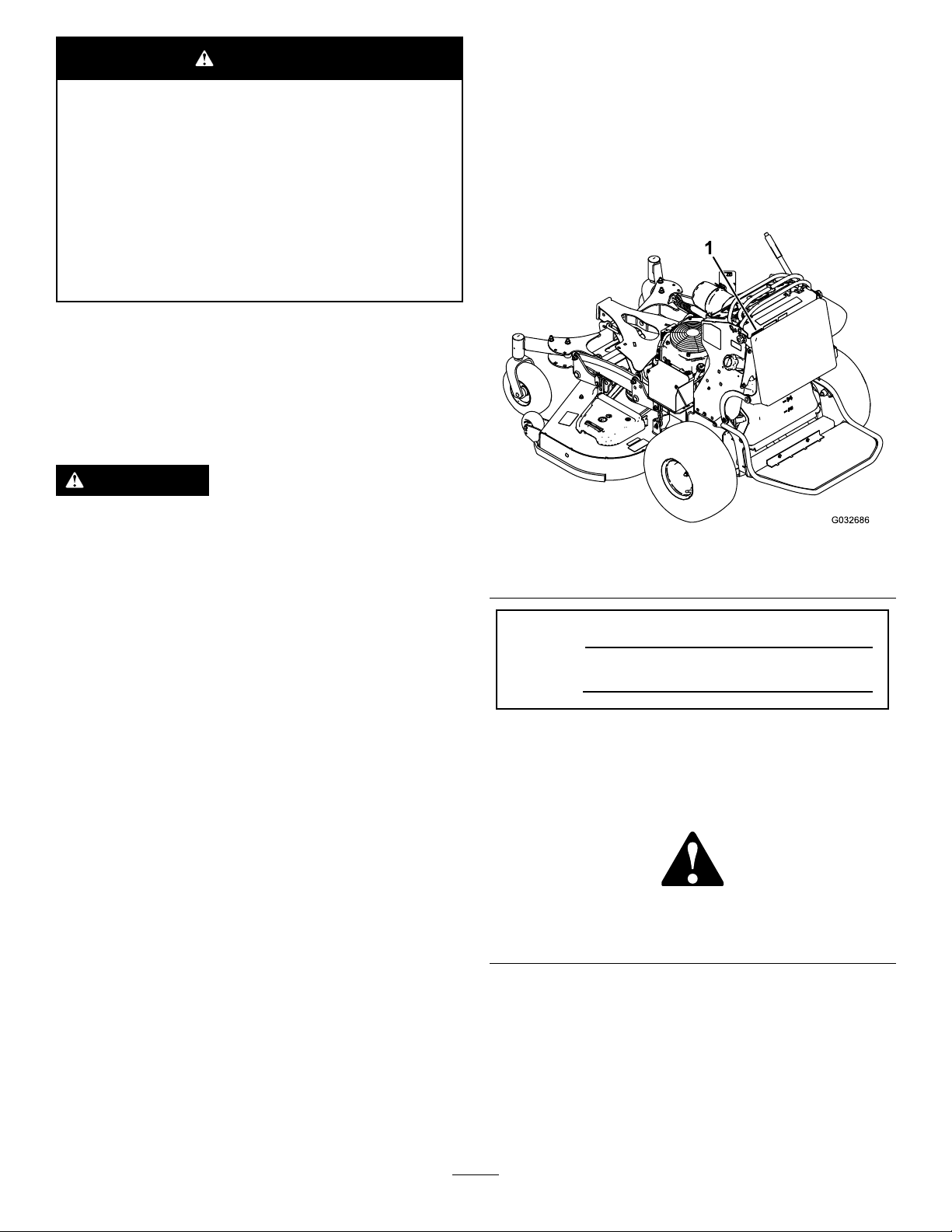
andserialnumbersofyourproductready.Figure1
identiesthelocationofthemodelandserialnumbers
ontheproduct.Writethenumbersinthespace
provided.
g032686
Figure1
1.Locationofthemodelandserialnumbers
ModelNo.
SerialNo.
Pleaserefertotheenginemanufacturer’sinformation
includedwiththemachine.
Introduction
Thisrotaryblade,ridinglawnmowerisintendedtobe
usedbyprofessional,hiredoperators,orresidential
homeowners.Itisdesignedprimarilyforcuttinggrass
onwell-maintainedlawnsonresidentialorcommercial
properties.Itisnotdesignedforcuttingbrushorfor
agriculturaluses.
Readthisinformationcarefullytolearnhowtooperate
andmaintainyourproductproperlyandtoavoid
injuryandproductdamage.Youareresponsiblefor
operatingtheproductproperlyandsafely .
YoumaycontactT orodirectlyatwww.Toro.com
forproductsafetyandoperationtrainingmaterials,
©2017—TheToro®Company
8111LyndaleAvenueSouth
Bloomington,MN55420
Thismanualidentiespotentialhazardsandhas
safetymessagesidentiedbythesafety-alertsymbol
(Figure2),whichsignalsahazardthatmaycause
seriousinjuryordeathifyoudonotfollowthe
recommendedprecautions.
Figure2
1.Safety-alertsymbol
Thismanualuses2wordstohighlightinformation.
Importantcallsattentiontospecialmechanical
informationandNoteemphasizesgeneralinformation
worthyofspecialattention.
Contactusatwww.Toro.com.
2
g000502
PrintedintheUSA
AllRightsReserved
Page 3

Contents
Safety.......................................................................4
SafeOperatingPractices....................................4
ToroMowerSafety..............................................6
SlopeIndicator...................................................7
SafetyandInstructionalDecals..........................8
ProductOverview...................................................12
Controls...........................................................12
Specications..................................................13
Attachments/Accessories.................................14
Operation................................................................14
ThinkSafetyFirst..............................................14
AddingFuel......................................................14
CheckingtheEngine-OilLevel..........................16
BreakinginaNewMachine..............................16
OperatingtheParkingBrake.............................16
OperatingtheMower-Blade-ControlSwitch
(PTO)............................................................17
OperatingtheThrottle.......................................17
OperatingtheKeySwitch.................................17
UsingtheFuel-ShutoffValve.............................18
StartingtheEngine...........................................18
ShuttingOfftheEngine.....................................19
TheSafety-InterlockSystem.............................19
OperatingthePlatform......................................20
DrivingForwardorBackward............................21
StoppingtheMachine.......................................22
PushingtheMachinebyHand..........................22
TransportingtheMachine.................................23
LoadingtheMachine........................................24
SideDischargingorMulchingthe
Grass............................................................25
AdjustingtheHeight-of-Cut...............................25
AdjustingtheAnti-ScalpRollers........................26
AdjustingtheFlowBafe..................................26
UsingtheMid-SizeWeight................................27
Maintenance...........................................................28
RecommendedMaintenanceSchedule(s)...........28
Pre-MaintenanceProcedures..............................29
ReleasingtheCushionforRearAccess............29
Lubrication..........................................................29
GreasingtheAccessoryFrame.........................29
GreasingtheT orsionIdler.................................30
GreasingtheFrontCasterPivots......................30
GreasingtheCaster-WheelHubs.....................30
GreasingtheVoltageRegulator........................31
GreasingtheBrakeCalipers.............................31
GreasingtheMotionControls...........................32
EngineMaintenance...........................................32
ServicingtheAirCleaner..................................32
ServicingtheEngineOil....................................34
ServicingtheSparkPlug...................................36
CheckingtheSparkArrester.............................37
FuelSystemMaintenance...................................38
DrainingtheFuelT ank......................................38
RemovingtheFuelT ank...................................38
ServicingtheFuelFilter...................................39
ElectricalSystemMaintenance...........................39
ServicingtheBattery.........................................39
ServicingtheFuses..........................................41
DriveSystemMaintenance..................................42
AdjustingtheTracking......................................42
CheckingtheTirePressure...............................42
AdjustingtheCaster-PivotBearing...................43
ServicingtheCasterWheelsand
Bearings........................................................43
UsingtheClutchShim......................................44
CheckingtheWheel-LugNuts..........................46
CheckingtheWheel-HubNuts..........................46
CoolingSystemMaintenance..............................46
CleaningtheAir-IntakeScreen.........................46
CleaningtheCoolingSystem............................46
BrakeMaintenance.............................................47
ServicingtheBrake..........................................47
BeltMaintenance................................................47
ReplacingtheMower-DeckBelt........................47
ReplacingtheTransmissionBelt......................48
ControlsSystemMaintenance.............................49
AdjustingtheMotion-ControlLevers.................49
HydraulicSystemMaintenance...........................50
ServicingtheHydraulicSystem........................50
MowerDeckMaintenance....................................52
RemovingtheMowerDeck...............................52
InstallingtheMowerDeck.................................54
ServicingtheBlades.........................................54
CorrectingtheQualityofCut.............................56
AdjustingtheDeck-LiftSpring...........................59
ReplacingtheGrassDeector..........................59
Cleaning..............................................................60
CleaningundertheMowerDeck.......................60
DisposingoftheWaste.....................................60
Storage...................................................................60
CleaningandStorage.......................................60
Troubleshooting......................................................62
Schematics.............................................................64
3
Page 4

Safety
Improperuseormaintenancebytheoperatoror
ownercanresultininjury.T oreducethepotential
forinjury,complywiththesesafetyinstructions,
andpayattentiontothesafetyalertsymbol,which
meansCaution,Warning,orDanger—personalsafety
instruction.Failuretocomplywiththeinstructions
mayresultinpersonalinjuryordeath.
Thismachinewasmanufacturedaccordingtothe
appropriateregulatorystandardsineffectatthetime
ofmanufacture.Modifyingthismachineinanyway
maycauseittobeoutofcompliancewiththose
standardsandwiththeinstructionsinthisOperator’s
Manual.Modicationstothismachineshouldonly
bemadebyeitherthemanufactureroranAuthorized
ToroDealer.
Thisproductiscapableofamputatinghandsandfeet.
Followallsafetyinstructionstoavoidseriousinjury
ordeath.
Theowner/usercanpreventandisresponsiblefor
accidentsorinjuriesoccurringtopeople,ordamage
toproperty.
Theadditionofattachmentsmadebyother
manufacturersthatdonotmeetAmericanNational
StandardsInstitutecerticationmaycause
noncomplianceofthismachine.
SafeOperatingPractices
ThefollowinginstructionsarefromANSIstandard
B71.4-2012.
Training
•ReadtheOperator'sManualandothertraining
material.Iftheoperator(s)ormechanic(s)cannot
readthemanuallanguage,itistheowner's
responsibilitytoexplainthismaterialtothem.
•Becomefamiliarwiththesafeoperationofthe
equipment,operatorcontrols,andsafetysigns.
•Alloperatorsandmechanicsshouldbetrained.
Theownerisresponsiblefortrainingtheusers.
•Neverletchildrenoruntrainedpeopleoperateor
servicetheequipment.Localregulationsmay
restricttheageoftheoperator.
•Theowner/usercanpreventandisresponsible
foraccidentsorinjuriesoccurringtohimselfor
herself,otherpeople,ordamagetoproperty.
Preparation
•Evaluatetheterraintodeterminewhataccessories
andattachmentsyouneedtoproperlyandsafely
performthejob.Useonlyaccessoriesand
attachmentsapprovedbythemanufacturer.
•Wearappropriateclothing;includingsafety
glasses,longpants,substantialslip-resistant
footwear,gloves,andhearingprotection.Tieback
longhair.Donotwearjewelry .
•Inspecttheareawhereyouwillusetheequipment
andensurethatallobjectsareremovedfromthe
areabeforeuse.
•Useextracarewhenhandlingfuels.Theyare
ammableandvaporsareexplosive.
–Useonlyanapprovedcontainer.
–Donotremovethefuelcaporaddfuelwiththe
enginerunning.Allowtheenginetocoolbefore
refueling.Donotsmokenearthemachine
whentheengineisrunning.
–Donotrefuelordrainthemachineindoors.
•Checkthattheoperator'spresencecontrols,safety
switches,andshieldsareattachedandfunctioning
properly.Donotoperatethemachineunlessthey
arefunctioningproperly.
Operation
•Lightningcancausesevereinjuryordeath.If
lightningisseen,orthunderisheardinthearea,
donotoperatethemachine;seekshelter.
•Donotrunanengineinanenclosedarea.
•Operateonlyinwell-litareas,keepingawayfrom
holesandhiddenhazards.
•Ensurethatalldrivesareinneutralandthatthe
parkingbrakeisengagedbeforestartingengine.
Starttheengineonlyfromtheoperator’sposition.
•Makesurethatyouhavegoodfootingwhile
usingthismachine,especiallywhenbackingup.
Reducedfootingcouldcauseslipping.
•Slowdownanduseextracareonhillsides.Be
suretotravelsidetosideonhillsides.Turf
conditionscanaffectthestabilityofthemachine.
Usecautionwhileoperatingneardrop-offs.
•Slowdownandusecautionwhenmakingturns
andwhenchangingdirectionsonslopes.
•Donotraisethemowerdeckwiththeblades
running.
•DonotoperatethemachinewithoutthePTO
shieldorotherguardssecurelyinplace.Besure
thatallinterlocksareattached,adjustedproperly,
andfunctioningproperly.
•Donotoperatewiththedischargedeectorraised,
removedoraltered,unlessyouareusingagrass
catcher.
4
Page 5

•Donotchangetheenginegovernorsettingor
overspeedtheengine.
•Stopthemachineonlevelground,disengagethe
drives,engagetheparkingbrake,andshutoffthe
enginebeforeleavingtheoperator'spositionfor
anyreason,includingemptyingthecatchersor
uncloggingthechute.
•Stopthemachineandinspectthebladesafter
strikingobjectsorifanabnormalvibrationoccurs.
Makethenecessaryrepairsbeforeresuming
operations.
•Keepyourhandsandfeetawayfromthecutting
unit.
•Lookbehindanddownbeforebackingupto
ensureaclearpath.
•Keeppetsandbystandersawayfromanoperating
machine.
•Slowdownandusecautionwhenmakingturns
andcrossingroadsandsidewalks.Stopthe
bladesifyouarenotmowing.
•Beawareofthemower-dischargedirectionand
donotpointitatanyone.
•Donotoperatethemachinewhiletired,ill,or
undertheinuenceofalcoholordrugs.
•Usecarewhenloadingorunloadingthemachine
intoorfromatrailerortruck.
•Usecarewhenapproachingblindcorners,shrubs,
trees,orotherobjectsthatmayobscurevision.
SafeHandlingofFuels
•Toavoidpersonalinjuryorpropertydamage,use
extremecareinhandlingfuel.Fuelisextremely
ammableandthevaporsareexplosive.
•Extinguishallcigarettes,cigars,pipes,andother
sourcesofignition.
•Useonlyanapprovedfuelcontainer.
•Donotremovethefuelcaporaddfuelwiththe
enginerunning.
•Allowtheenginetocoolbeforefueling.
•Donotfuelthemachineindoors.
•Donotstorethemachineorfuelcontainerwhere
thereisanopename,spark,orpilotlight,such
asonawaterheateroronotherappliances.
•Donotllcontainersinsideavehicle,onatruck,
oronatrailerbedwithaplasticliner.Alwaysplace
containersonthegroundawayfromyourvehicle
beforelling.
•Removeequipmentfromthetruckortrailerand
fuelitontheground.Ifthisisnotpossible,
thenaddfuelwithsuchequipmentasaportable
containerratherthanfromafuel-dispensernozzle.
•Keepthenozzleincontactwiththerimofthefuel
tankorcontaineropeningatalltimesuntilfueling
iscomplete.Donotuseanozzlelock-opendevice.
•Ifyouspillfuelonclothing,changeyourclothing
immediately.
•Donotoverllthefueltank.Replacethefuelcap
andtightenitsecurely.
MaintenanceandStorage
•Disengagedrives,engagetheparkingbrake,shut
offtheengine,andremovethekeyordisconnect
spark-plugwire.Waitforallmovementtostop
beforeadjusting,cleaning,orrepairing.
•Cleangrassanddebrisfromthecuttingunit,
drives,mufers,andenginetohelppreventres.
•Cleanupoilorfuelspills.
•Lettheenginecoolbeforestoringthemachine.
•Donotstorefuelnearamesordrainthefuel
indoors.
•Donotallowuntrainedpersonneltoservicethe
machine.
•Usejackstandstosupportcomponentswhen
required.
•Carefullyreleasepressurefromcomponentswith
storedenergy.
•Disconnectthebatteryorremovethespark-plug
wirebeforemakinganyrepairs.Disconnectthe
negativeterminalrstandthepositiveterminal
last.Connectthepositiveterminalrstand
negativelast.
•Usecarewhencheckingtheblades.Wrapthe
blade(s)orweargloves,andusecautionwhen
servicingthem.Onlyreplaceblades;donot
straightenorweldthem.
•Keephandsandfeetawayfrommovingparts.If
possible,donotmakeadjustmentswiththeengine
running.
•Keepallpartsingoodworkingconditionandall
hardwaretightened.Replaceallwornordamaged
decals.
Hauling
•Usecarewhenloadingorunloadingthemachine
intoatraileroratruck.
•Usefull-widthrampsforloadingmachineintoa
traileroratruck.
•Tiethemachinedownsecurelyusingstraps,
chains,cable,orropes.Bothfrontandrearstraps
shouldbedirecteddownandoutwardfromthe
machine.
5
Page 6

ToroMowerSafety
SlopeOperation
Thefollowinglistcontainssafetyinformationspecic
toT oroproductsandothersafetyinformationthatyou
mustknow.
Thisproductiscapableofamputatinghandsand
feetandofthrowingobjects.Alwaysfollowallsafety
instructionstoavoidseriousinjuryordeath.
Thisproductisdesignedforcuttingandrecycling
grass,or,whenequippedwithagrassbagger,for
catchingcutgrass.Anyuseforpurposesother
thanthesecouldprovedangeroustotheuserand
bystanders.
GeneralOperation
•Besurethattheareaisclearofbystandersbefore
mowing.Stopthemachineifanyoneentersthe
area.
•Donottouchequipmentorattachmentpartswhich
maybehotfromoperation.Allowalloftheparts
tocoolbeforeattemptingtomaintain,adjust,or
servicethemachine.
•UseonlyToro-approvedattachments.Warranty
maybevoidedifusedwithanyunapproved
attachments.
•Checkcarefullyforoverheadclearances(i.e.,
branches,doorways,electricalwires,etc.)before
operatingunderanyobjects,anddonotcontact
them.
•Slowdownbeforemakingturnsanduseextra
caution.
•Usecautionwhenridingtheplatformovercurbs,
rocks,roots,orotherobstructions.
•Lookbehindanddownbeforebackinguptoensure
aclearpath.Useextracarewhenoperatingthe
machineinreverse.
•Donotjerkthecontrols;useasteadymotion.
•Whenloadingorunloadingthemachine,useone
full-widthrampthatiswideenoughtoextend
beyondthewidthofthemachine.
•Donotcarrypassengers.
Allslopesandrampsrequireextracaution.Ifyoufeel
uneasyonaslope,donotmowit.
•Removeobstaclessuchasrocks,treelimbs,etc.
fromthemowingarea.
•Watchforholes,rutsorbumps.T allgrasscan
hideobstacles.
•Usecautionneardrop-offs,ditches,or
embankments.Themachinecouldsuddenlyturn
overifawheelgoesovertheedgeofacliffor
ditch,orifanedgecavesin.
•Useextracarewithgrasscatchersorother
attachments.Thesecanchangethestabilityof
themachine.
•Keepallmovementonslopesslowandgradual.
•Donotmakesuddenchangesinspeedor
direction.
•Mowslopessidetoside.
•Donotmowslopesgreaterthan20degrees.
Service
•Donotstorethemachineorafuelcontainerinside
wherethereisanopename,suchasneara
waterheaterorfurnace.
•Keepthenutsandboltstight,especiallythe
blade-attachmentbolts.
•Neverremoveortamperwithsafetydevices.
Checktheirproperoperationregularly.Neverdo
anythingtointerferewiththeintendedfunctionofa
safetydeviceortoreducetheprotectionprovided
byasafetydevice.
•Tobestprotectyourinvestmentandmaintain
optimalperformanceofyourToroequipment,count
onT orogenuineparts.Whenitcomestoreliability ,
Torodeliversreplacementpartsdesignedtothe
exactengineeringspecicationsofourequipment.
Forpeaceofmind,insistonT orogenuineparts.
•Checktheoperationofthebrakesfrequently.
Adjustandservicethemasrequired.
•Donotcarryequipmentonthemachine.
6
Page 7
SlopeIndicator
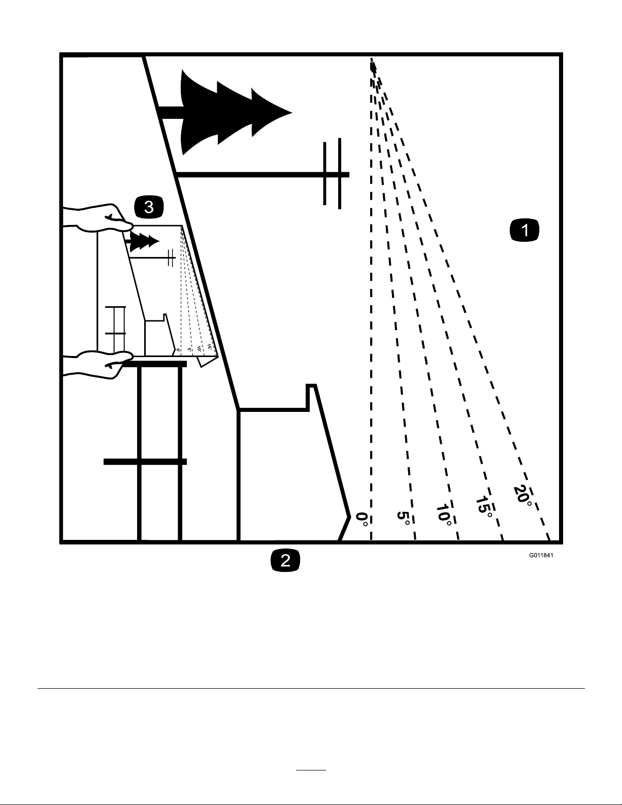
Figure3
Thispagemaybecopiedforpersonaluse.
1.Themaximumslopeyoucansafelyoperatethemachineonis20degrees.Usetheslopecharttodeterminethedegreeofslope
ofhillsbeforeoperating.Donotoperatethismachineonaslopegreaterthan20degrees.Foldalongtheappropriateline
tomatchtherecommendedslope.
2.Alignthisedgewithaverticalsurface,atree,building,fencepole,etc.
3.Exampleofhowtocompareslopewithfoldededge
7
g011841
Page 8
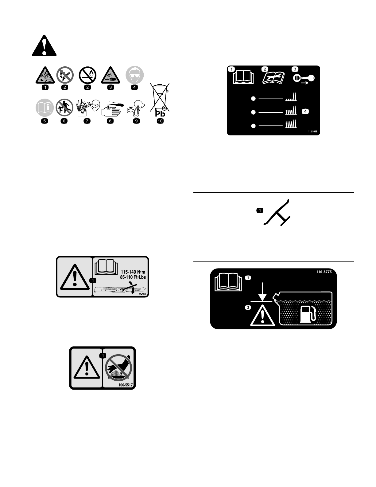
SafetyandInstructionalDecals
Safetydecalsandinstructionsareeasilyvisibletotheoperatorandarelocatednearanyarea
ofpotentialdanger.Replaceanydecalthatisdamagedormissing.
BatterySymbols
Someorallofthesesymbolsareonyourbattery .
1.Explosionhazard
2.Nore,opename,or
smoking
3.Causticliquid/chemical
burnhazard
4.Weareyeprotection.9.Flusheyesimmediately
5.ReadtheOperator's
Manual.
6.Keepbystandersasafe
distanceawayfromthe
battery.
7.Weareyeprotection;
explosivegasescan
causeblindnessandother
injuries.
8.Batteryacidcancause
blindnessorsevereburns.
withwaterandgetmedical
helpfast.
10.Containslead;donot
discard
decalbatterysymbols
decal112-3858
112-3858
1.ReadtheOperator's
Manual.
2.Readtheinstructions
beforeservicingor
performingmaintenance.
3.Removethekeybefore
adjustingtheheightofcut.
4.Height-of-cutsettings.
decaloemmarkt
Manufacturer'sMark
1.Indicatesthebladeisidentiedasapartfromtheoriginal
machinemanufacturer.
93-7818
1.Warning—readtheOperator'sManualforinstructionson
torquingthebladebolt/nutto1 15to149N∙m(85to110
ft-lb).
106-5517
1.Warning—donottouchthehotsurface.
decal93-7818
decal116-8775
116-8775
1.ReadtheOperator’s
Manual.
decal106-5517
2.Filltobottomofllerneck;
warning—donotoverll
thetank.
8
Page 9

131-1180
131-3528
15A 15A 10A
7.5A
1.ReadtheOperator'sManual.(A)Short,lightgrass;dry
conditions;maximumdispersion;(B)Baggingsetting;(C)
Tall,densegrass;wetconditions;maximumgroundspeed
decal131-3521
131-3521
1.Heightofcut
decal131-1180
decal131-3524
131-3524
1.ReadtheOperator's
Manual.
1.ReadtheOperator's
3.Fluidlevel
Manual.
2.Transmissionuid
decal131-3507
131-3507
2.Belttensioner
decal131-3528
131-3528
1.Keyswitch—15A
2.Accessoryport—15A
3.Powertakeoff(PTO)—10
A
4.Infocenter—7.5A
9
Page 10
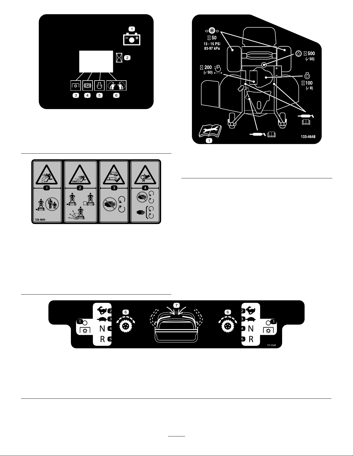
131-3536
1.Battery4.Parkingbrake
2.Time5.Engine—start
3.Powertakeoff(PTO)
6.Engagethehandlebars.
133-4604
decal131-3536
decal133-4648
133-4648
1.ReadtheOperator'sManualformoreinformationon
servicingthemachine.
decal133-4604
1.Thrownobject
hazard—keepbystanders
awayfromthemachine.
2.Thrownobjecthazard,
openbafe—onlyoperate
themachinewithabafe
oragrasscollector.
3.Severinghazardofhand
orfoot—keepawayfrom
movingparts.
4.Entanglement
hazard—keepaway
frommovingparts;keep
allguardsandshieldsin
place.
131-3526
1.Powertakeoff(PTO)—disengaged
2.Fast6.Tractiondrive
3.Slow
4.Neutral
5.Reverse
7.Engagethehandles.
decal131-3526
10
Page 11

decal131-3527
131-3527
1.Warning—readtheOperator'sManual.5.Thrownobjecthazard—keepbystandersawayfromthe
machine.
2.Warning—receivetrainingbeforeoperatingthemachine.6.Warning—1)Engagetheparkingbrake,shutofftheengine,
andremovethekeyfromtheswitch;2)ReadtheOperator's
Manualbeforeservicingorperformingmaintenance.
3.Thrownobjecthazard—keepthedeectorloweredduring
operation.
4.Cutting/severinghazardofhandorfoot—keepawayfrom
7.Warning—engagetheparkingbrake,shutofftheengine,and
removethekeyfromtheswitchbeforeleavingthemachine.
8.Tippinghazard—donotoperateneardrop-offsornearwater.
movingparts;keepallguardsandshieldsinplace.
133-1432
1.Disengagetheparkingbrake.
2.Engagetheparkingbrake.
3.PulluptoturnonthePTO.
4.PushdowntoturnoffthePTO.
5.Enginespeed—fast
6.Enginespeed—slow
decal133-1432
11
Page 12
ProductOverview
Controls
Becomefamiliarwithallthecontrolsbeforeyoustart
theengineandoperatethemachine(Figure5).
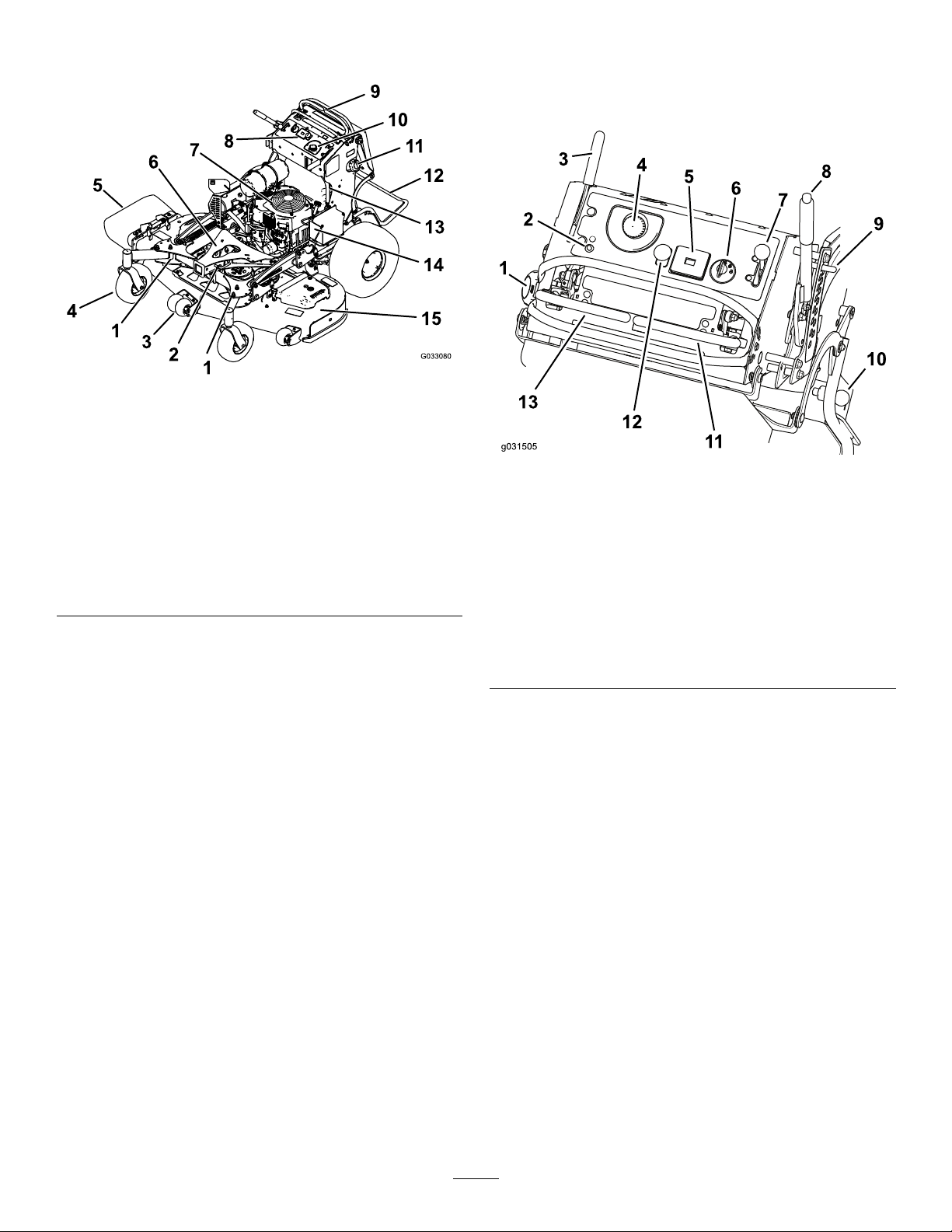
g033080
Figure4
1.Adjustablecaster
2.Accessory-framelock
3.Anti-scalproller(60-inch
decksonly)
4.Frontcasterwheel
5.Side-dischargechute13.Fuel-shutoffvalve
6.Accessoryframe
7.Engine15.Mowerdeck
8.Controls
9.Controllevers
10.Hydraulictank
11.Fueltank
12.Platform(downposition)
14.Battery
Figure5
1.Fuelcap
2.Malfunction-indicatorlight
(MIL)
3.Parking-brakelever
4.Hydraulic-tankcap11.Rightmotion-controllever
5.Hourmeter12.Blade-controlswitch
6.Keyswitch
7.Throttlecontrol
8.Height-of-cutlever
9.Height-of-cutpin
10.Platformlatch
(PTO)
13.Leftmotion-controllever
Electronic-ControlUnit
Malfunction-IndicatorLight
Theelectronic-controlunit(ECU)continuously
monitorstheoperationoftheEFIsystem.
Ifaproblemorfaultwithinthesystemisdetected,the
malfunction-indicatorlight(MIL)isilluminated(Figure
5).
g031505
TheMIListheredlightlocatedintheconsolepanel.
WhentheMILilluminates,makeinitialtroubleshooting
checks.
Ifthesechecksdonotcorrecttheproblem,further
diagnosisandservicingbyanAuthorizedService
Dealerisnecessary.
HourMeter
Thehourmeterrecordsthenumberofhoursthe
enginehasoperated.Itoperateswhentheengine
12
Page 13
isrunning.Usethesetimesforschedulingregular
maintenance(Figure5).
Safety-InterlockIndicators
Symbolsonthehourmeterindicatewithablack
trianglethattheinterlockcomponentisinthecorrect
position(Figure5).
Battery-IndicatorLight
IfthekeyisturnedtotheONpositionforafew
seconds,thebatteryvoltagedisplaysinthearea
wherethehoursarenormallydisplayed.
Thebatterylightturnsonwhenthekeyisturnedtothe
ONpositionandwhenthechargeisbelowthecorrect
operatinglevel(Figure5).
ThrottleControl
ThethrottlecontrolisvariablebetweenFastand
Slow(Figure5).
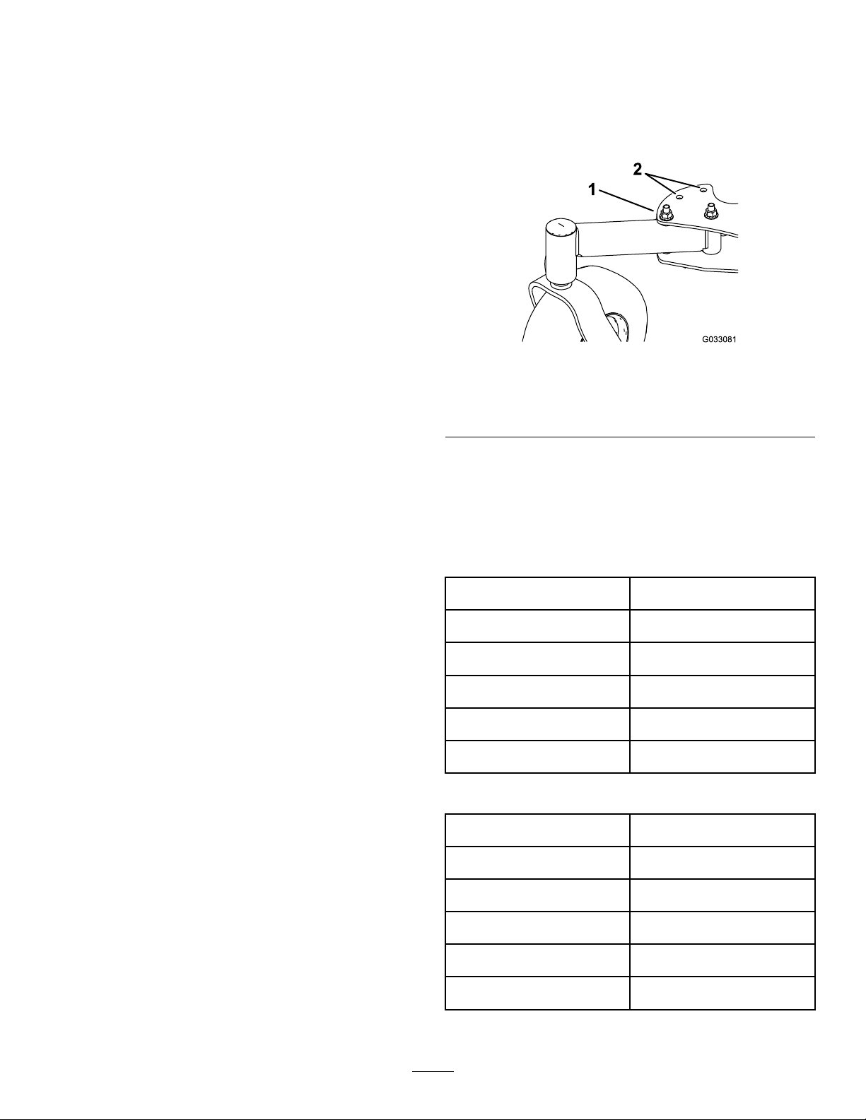
AdjustableCasters
Whenusingthemachinewithoutanaccessory,place
theadjustablecastersinthemowingposition(front
hole)asshowninFigure6.Whenusingthemachine
withanaccessory,refertotheOperator’sManualfor
thataccessoryforthecorrectcasterposition.
g033081
Figure6
RightCasterShown
1.Mowingposition2.Accessorypositions
Blade-ControlSwitch(PTO)
Usetheblade-controlswitch(PTO)toengageand
disengagethemowerblades(Figure5).
KeySwitch
Thekeyswitch,usedtostartandshutofftheengine,
has3positions:OFF,RUN,andSTART.Referto
OperatingtheKeySwitch(page17).
Motion-ControlLevers
Usethemotion-controlleverstodrivethemachine
forward,reverse,andturneitherdirection(Figure5).
Fuel-ShutoffValve
Closethefuel-shutoffvalvewhentransportingor
storingthemachine;refertoUsingtheFuel-Shutoff
Valve(page18).
AccessoryFrame
UsetheaccessoryframetoattachonlyToro-approved
accessoriestothemachine(Figure4).Refertothe
Operator’sManualfortheaccessoryforinstallation
instructions.
Specications
Note:Specicationsanddesignaresubjectto
changewithoutnotice.
52-inchMowers
Widthwithdeectordown173cm(68inches)
Widthwithdeectorraised137cm(54inches)
Lengthwithplatformdown191cm(75inches)
Lengthwithplatformup155cm(61inches)
Height
Weight
60-inchMowers
Widthwithdeectordown193cm(76inches)
Widthwithdeectorraised157cm(62inches)
Lengthwithplatformdown201cm(79inches)
Lengthwithplatformup165cm(65inches)
122cm(48inches)
412kg(908lb)
Accessory-FrameLock
Theaccessory-framelockholdstheframeinplaceon
themachineusingthelockpin.Alwayslocktheframe
unlessahydraulickitisinstalledwithanaccessory
onthemachine(Figure4).
Height
Weight
13
122cm(48inches)
427kg(941lb)
Page 14

Attachments/Accessories
AselectionofToroapprovedattachmentsand
accessoriesisavailableforusewiththemachineto
enhanceandexpanditscapabilities.Contactyour
AuthorizedServiceDealerorDistributororgoto
www.T oro.comforalistofallapprovedattachments
andaccessories.
Operation
Note:Determinetheleftandrightsidesofthe
machinefromthenormaloperatingposition.
ThinkSafetyFirst
Tobestprotectyourinvestmentandmaintainoptimal
performanceofyourToroequipment,countonT oro
genuineparts.Whenitcomestoreliability,T oro
deliversreplacementpartsdesignedtotheexact
engineeringspecicationofourequipment.Forpeace
ofmind,insistonTorogenuineparts.
Carefullyreadallthesafetyinstructionsanddecals
inthesafetysection.Knowingthisinformationcould
helpyouorbystandersavoidinjury.
CAUTION
Thismachineproducessoundlevelsin
excessof85dBAattheoperator'searand
cancausehearinglossfromextendedperiods
ofexposure.
Wearhearingprotectionwhenoperatingthis
machine.
g229846
Figure7
1.Wearhearingprotection.
AddingFuel
•Forbestresults,useonlyclean,fresh(lessthan
30daysold),unleadedgasolinewithanoctane
ratingof87orhigher((R+M)/2ratingmethod).
•Ethanol:Gasolinewithupto10%ethanol
(gasohol)or15%MTBE(methyltertiarybutyl
ether)byvolumeisacceptable.Ethanoland
MTBEarenotthesame.Gasolinewith15%
ethanol(E15)byvolumeisnotapprovedforuse.
Neverusegasolinethatcontainsmorethan
10%ethanolbyvolume,suchasE15(contains
15%ethanol),E20(contains20%ethanol),orE85
(containsupto85%ethanol).Usingunapproved
gasolinemaycauseperformanceproblemsand/or
enginedamagewhichmaynotbecoveredunder
warranty.
•Donotusegasolinecontainingmethanol.
•Donotstorefueleitherinthefueltankorfuel
containersoverthewinterunlessyouuseafuel
stabilizer.
•Donotaddoiltogasoline.
14
Page 15

DANGER
DANGER
Incertainconditions,fuelisextremely
ammableandhighlyexplosive.Areor
explosionfromfuelcanburnyouandothers
andcandamageproperty .
•Fillthefueltankoutdoors,inanopenarea,
whentheengineiscold.Wipeupanyfuel
thatspills.
•Neverllthefueltankinsideanenclosed
trailer.
•Donotllthefueltankcompletelyfull.
Addfueltothefueltankuntilthelevelis6
to13mm(1/4to1/2inch)belowthebottom
ofthellerneck.Thisemptyspaceinthe
tankallowsfueltoexpand.
•Neversmokewhenhandlingfuel,andstay
awayfromanopenameorwherefuel
fumesmaybeignitedbyaspark.
•Storefuelinanapprovedcontainerand
keepitoutofthereachofchildren.Never
buymorethana30-daysupplyoffuel.
•Donotoperatewithoutentireexhaust
systeminplaceandinproperworking
condition.
Incertainconditionsduringfueling,static
electricitycanbereleasedcausingaspark,
whichcanignitethefuelvapors.Areor
explosionfromfuelcanburnyouandothers
andcandamageproperty .
•Alwaysplacefuelcontainersontheground
awayfromyourvehiclebeforelling.
•Donotllfuelcontainersinsideavehicle
oronatruckortrailerbedbecauseinterior
carpetsorplastictruckbedlinersmay
insulatethecontainerandslowthelossof
anystaticcharge.
•Whenpractical,removegas-powered
equipmentfromthetruckortrailerand
refueltheequipmentwithitswheelsonthe
ground.
•Ifthisisnotpossible,thenrefuelsuch
equipmentonatruckortrailerfroma
portablecontainerratherthanfroma
fuel-dispensernozzle.
•Ifyoumustuseafuel-dispensernozzle,
keepthenozzleincontactwiththerimof
thefueltankorcontaineropeningatall
timesuntilfuelingiscomplete.
WARNING
Fuelisharmfulorfatalifswallowed.
Long-termexposuretovaporscancause
seriousinjuryandillness.
•Avoidprolongedbreathingofvapors.
•Keepfaceawayfromnozzleandfueltank
orconditionerbottleopening.
•Avoidcontactwithskin;washoffspills
withsoapandwater.
UsingStabilizer/Conditioner
Useafuelstabilizer/conditionerinthemachineto
providethefollowingbenets:
•Keepsfuelfreshduringstorageof90daysorless.
Forlongerstorage,drainthefueltank.
•Cleanstheenginewhileitruns
•Eliminatesgum-likevarnishbuildupinthefuel
system,whichcauseshardstarting
Important:Donotusefueladditives
containingmethanolorethanol.
Addthecorrectamountoffuelstabilizer/conditioner
tothefuel.
15
Page 16

Note:Afuelstabilizer/conditionerismost
effectivewhenmixedwithfreshfuel.T ominimize
thechanceofvarnishdepositsinthefuelsystem,
usefuelstabilizeratalltimes.
FillingtheFuelTank
OperatingtheParking Brake
Alwaysengagetheparkingbrakewhenyoustopthe
machineorleaveitunattended.Beforeeachuse,
checktheparkingbrakeforproperoperation.
1.Parkthemachineonalevelsurface,disengage
thePTO,movethemotion-controlleverstothe
NEUTRAL-LOCKposition,andengagetheparking
brake.
2.Shutofftheengine,removethekey,andwait
forallmovingpartstostopbeforeleavingthe
operatingposition.
3.Cleanaroundthefuel-tankcapandremovethe
cap.
4.Fillthefueltanktothebottomofthellerneck.
Note:Donotllthefueltankcompletelyfull.
Theemptyspaceinthetankallowsthegasoline
toexpand.
5.Installthefuel-tankcapsecurely.Wipeupany
spilledfuel.
CheckingtheEngine-Oil Level
Beforeyoustarttheengineandusethemachine,
checktheoillevelintheenginecrankcase;referto
CheckingtheEngine-OilLevel(page34).
Iftheparkingbrakedoesnotholdsecurely,adjustit;
refertoAdjustingtheBrakes(page47).
CAUTION
Childrenorbystandersmaybeinjuredifthey
moveorattempttooperatethemachinewhile
itisunattended.
Alwaysremovethekeyandengagethe
parkingbrakewhenleavingthemachine
unattended.
EngagingtheParkingBrake
Pulltheparking-brakeleverrearwardintothe
ENGAGEDposition(Figure8).
BreakinginaNewMachine
Newenginestaketimetodevelopfullpower.Mower
decksanddrivesystemshavehigherfrictionwhen
new,placingadditionalloadontheengine.Allow
40to50hoursofbreak-intimefornewmachinesto
developfullpowerandbestperformance.
g009465
Figure8
1.Parkingbrake—engaged2.Parking
brake—disengaged
DisengagingtheParkingBrake
Pushtheparking-brakeleverforward(Figure8).
16
Page 17

Operatingthe
OperatingtheThrottle
Mower-Blade-Control
Switch(PTO)
Usetheblade-controlswitch(PTO)inconjunctionwith
themotion-controlleverstoengageanddisengage
themowerblades.
EngagingtheMowerBlades(PTO)
Figure9
YoucanmovethethrottlecontrolbetweenFASTand
SLOWpositions(Figure12).
AlwaysusetheFASTpositionwhenengagingthePTO.
g008946
Figure12
OperatingtheKeySwitch
Important:Donotengagethestarterformore
than5secondsatatime.Iftheenginefailsto
start,wait15secondsbetweenattempts.Failure
tofollowtheseinstructionscanburnoutthe
startermotor.
g031592
Note:Y oumayneedtorepeatthecycleforstarting
theenginewhenyoustartitforthersttimeafteryou
havelledacompletelyemptyfuelsystemwithfuel.
DisengagingtheMowerBlades (PTO)
Figure10andFigure11show2waystodisengage
themowerblades.
Figure10
Figure11
g031239
Figure13
g009174
g031281
Figure14
g031593
17
Page 18
UsingtheFuel-Shutoff
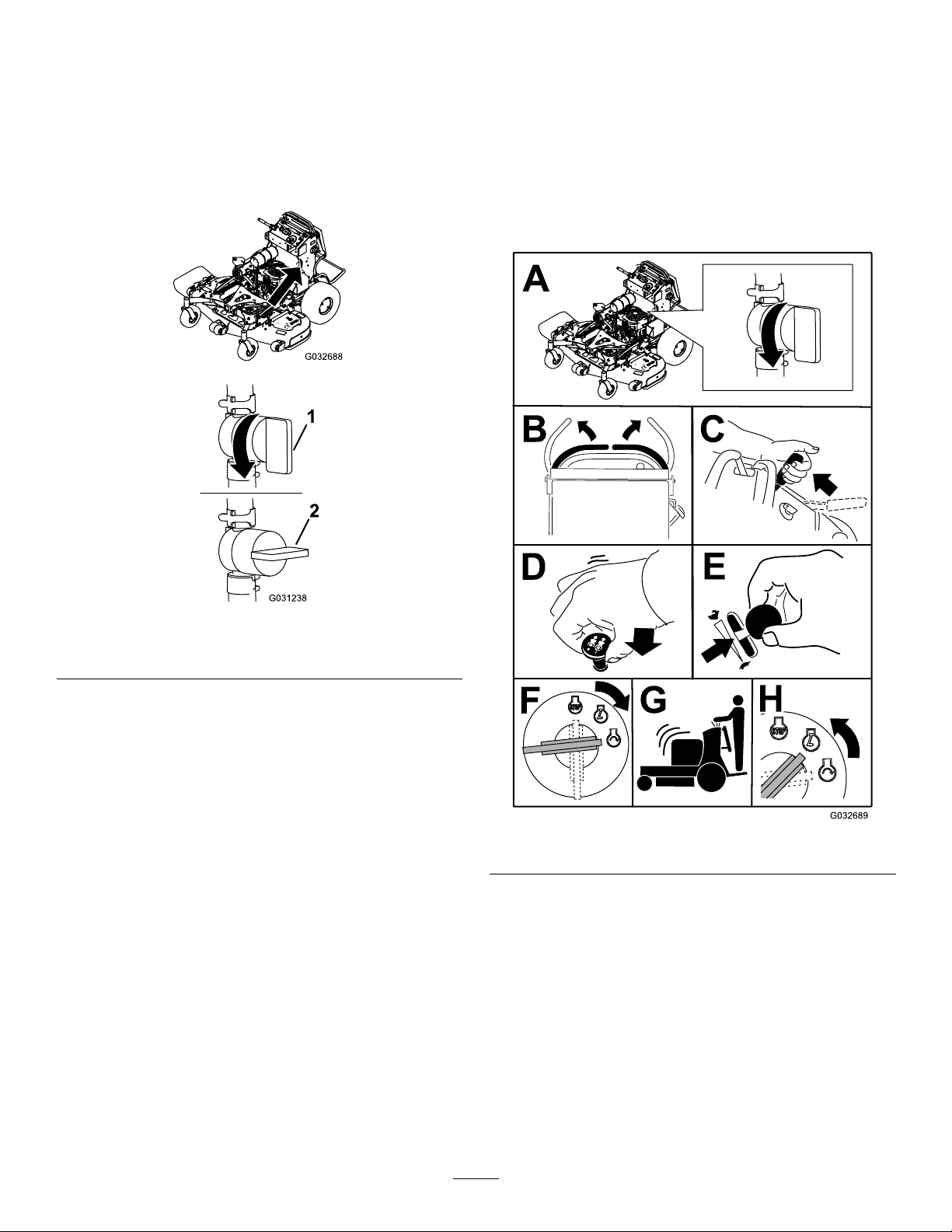
StartingtheEngine
Valve
Closethefuel-shutoffvalvefortransport,maintenance,
andstorage(Figure15).
Ensurethatthefuel-shutoffvalveisopenwhen
startingtheengine.
Important:Donotengagethestarterformore
than5secondsatatime.Iftheenginefailsto
start,wait15secondsbetweenattempts.Failure
tofollowtheseinstructionscanburnoutthe
startermotor.
Note:Y oumayneedtorepeatthecycleforstarting
theenginewhenyoustartitforthersttimeafteryou
havelledacompletelyemptyfuelsystemwithfuel.
g032688
Figure15
1.ONposition2.OFFposition
g031238
g032689
Figure16
18
Page 19
ShuttingOfftheEngine
CAUTION
TheSafety-Interlock
System
Childrenorbystandersmaybeinjuredifthey
moveorattempttooperatethemachinewhile
itisunattended.
Alwaysremovethekeyandengagethe
parkingbrakewhenleavingthemachine
unattended.
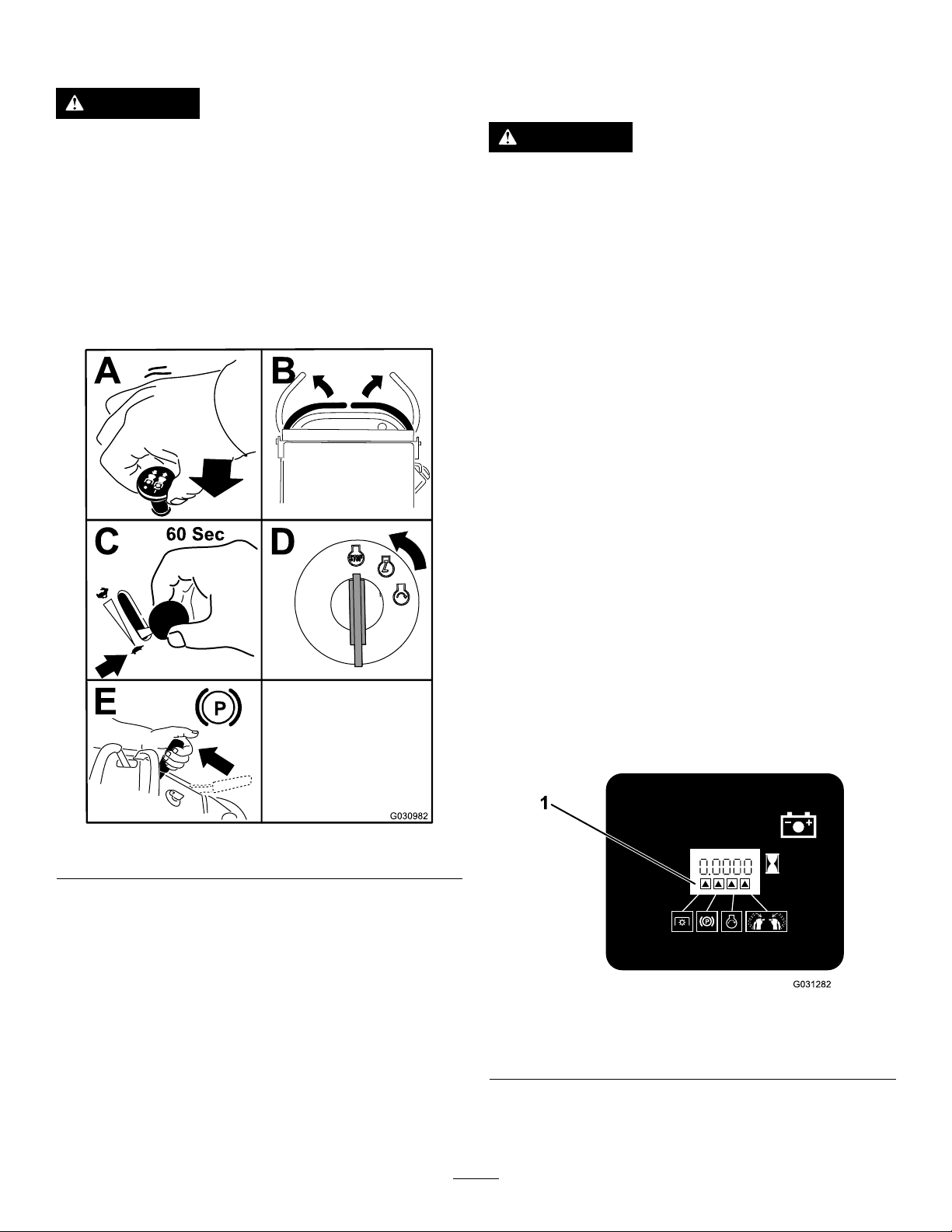
Lettheengineidleatslowthrottle(turtle)for60
secondsbeforeturningthekeyswitchtotheOFF
position.
CAUTION
Ifthesafety-interlockswitchesare
disconnectedordamaged,themachinecould
operateunexpectedly,causingpersonal
injury.
•Donottamperwiththeinterlockswitches.
•Checktheoperationoftheinterlock
switchesdailyandreplaceanydamaged
switchesbeforeoperatingthemachine.
Understandingthe Safety-InterlockSystem
Thesafety-interlocksystemisdesignedtoprevent
themowerbladesfromrotatingunlessyoudo1of
thefollowing:
•Moveeithermotion-controllevertothecenter,
unlockedposition.
•Pulltheblade-controlswitch(PTO)totheON
position.
Figure17
Important:Makesurethatthefuel-shutoffvalve
isclosedbeforetransportingorstoringthe
machinetopreventafuelleak.Beforestoringthe
machine,disconnectthesparkplug(s)toprevent
thepossibilityofaccidentalstarting.
Thesafety-interlocksystemisdesignedtostop
themowerbladesifyoumoveorreleaseboth
motion-controlleversintotheNEUTRAL-LOCK
position.
Thehourmeterhassymbolstonotifytheuser
wheneachinterlockcomponentisinthecorrect
position.Whenthecomponentisinthecorrect
position,atrianglelightsupinthecorresponding
square(Figure18).
g030982
g031282
Figure18
1.Triangleslightupwhentheinterlockcomponentsareinthe
correctposition.
19
Page 20

TestingtheSafety-Interlock System
ServiceInterval:Beforeeachuseordaily
Testthesafety-interlocksystembeforeyouusethe
machineeachtime.
Note:Ifthesafetysystemdoesnotoperateas
describedbelow,haveanAuthorizedServiceDealer
repairthesafetysystemimmediately.
1.Starttheengine;refertoStartingtheEngine
(page18).
2.Movethemotion-controlleverstothecenter,
unlockedposition.
Note:Thebladesshouldnotrotateandthe
engineshouldshutoff.
3.Starttheengineandreleasetheparkingbrake.
4.Moveeithermotion-controllevertothecenter,
unlockedposition.
5.Continueholdingthemotion-controlleverin
thecenter,unlockedposition,pulluponthe
blade-controlswitch(PTO),andreleasethe
switch.
WARNING
Theoperatorplatformisheavyandmaycause
injurywhenloweringandraisingtheoperator
platform.Carefullylowerorraisetheoperator
platform,assuddenlydroppingitcouldinjure
you.
•Donotputyourhandsorngersinthe
platform-pivotareawhenloweringor
raisingtheoperatorplatform.
•Makesurethattheplatformissupported
whenyoupullthelatchpinout.
•Makesurethatthelatchsecuresthe
platformwhenfoldingitup.Pushittight
againstthecushionforthelatchpinto
lockintoplace.
•Keepbystandersawaywhenraisingor
loweringtheplatform.
OperatingthePlatform
Youcanusethemachinewiththeplatforminthe
upordownposition.Itisyourpreferenceonwhich
positiontouse.
Note:Theclutchshouldengageandthemower
bladesrotate.
6.Moveorreleasethemotion-controlleversinto
theNEUTRAL-LOCKposition.
Note:Thebladesshouldstoprotatingandthe
engineshouldcontinuetorun.
7.Pushtheblade-controlswitchdownand
moveeithermotion-controllevertothecenter,
unlockedposition.
8.Continueholdingthemotion-controlleverin
thecenter,unlockedposition,pulluponthe
blade-controlswitch(PTO),andreleasethe
switch.
Note:Theclutchshouldengageandthemower
bladesshouldrotate.
9.Pushtheblade-controlswitch(PTO)downto
theOFFposition.
Note:Thebladesshouldstoprotating.
10.Withtheenginerunning,pulluptheblade-control
switch(PTO)andreleaseitwithoutholding
eithermotion-controllevertothecenter,
unlockedposition.
Note:Thebladesshouldnotrotate.
OperatingtheMachinewiththe PlatformUp
Operatethemachinewiththeplatformupforthe
followingconditions:
•Mowingneardrop-offs
•Mowingsmallareaswherethemachineistoo
large
•Areaswithlow,over-hangingbranchesor
obstacles
•Loadingthemachinefortransport
•Drivingupslopes
Toraisetheplatform,pullthebackoftheplatformup
sothatthelatchpinandknoblockitintoplace.Push
ittightagainstthecushionforthelatchpintolockit
intoplace.
OperatingtheMachinewiththe PlatformDown
Operatethemachinewiththeplatformdownforthe
followingconditions:
•Mowingmostareas
•Drivingacrossslopes
•Drivingdownslopes
Tolowertheplatform,pushtheplatformforward
againstthecushiontoreleasepressureonthelatch
20
Page 21
pin,thenpulltheknoboutandlowertheplatform
(Figure19).
Figure19
1.Platformup
2.Platformdown
3.Pulltheknobouttorelease
theplatform.
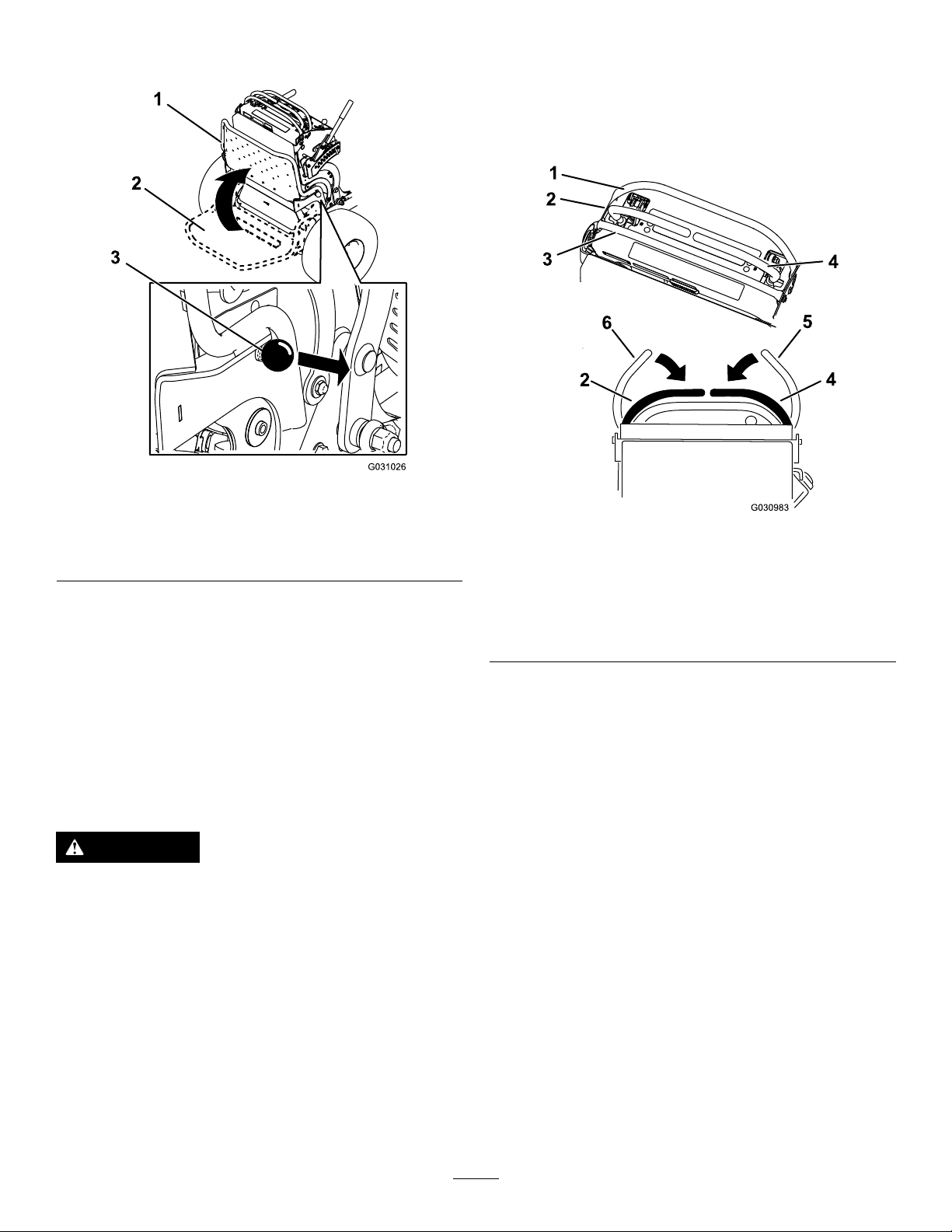
DrivingForwardor
DrivingForward
1.Disengagetheparkingbrake;referto
DisengagingtheParkingBrake(page16).
2.Movethemotion-controlleverstothecenter,
unlockedposition.
g031026
g030983
Figure20
1.Frontreferencebar
2.Leftcontrollever
3.Rearreferencebar6.Leftcontrolleverinthe
4.Rightcontrollever
5.Rightcontrolleverinthe
NEUTRAL-LOCKposition
NEUTRAL-LOCKposition
Backward
Thethrottlecontrolregulatestheenginespeedas
measuredinrpm(revolutionsperminute).Place
thethrottlecontrolintheFASTpositionforbest
performance.
Important:Backthemachineovercurbs;driving
itforwardovercurbscoulddamagethemachine.
CAUTION
Themachinecanspinveryrapidly,andyou
maylosecontrolofthemachine,causing
personalinjurytoyouanddamagetothe
machine.
Slowdownthemachinebeforemakingsharp
turns.
3.Slowlypushthemotion-controlleversforward
(Figure21).
Note:Theengineshutsoffifyoumovea
motion-controlleverwhiletheparkingbrakeis
engaged.
Note:Thefartheryoumovethemotion-control
leversineitherdirection,thefasterthemachine
movesinthatdirection.
Note:T ostop,pullthemotion-controllevers
backtotheNEUTRALposition.
21
Page 22

Figure21
StoppingtheMachine
Tostopthemachine,movethemotion-controllevers
toneutral,thenmovetherightmotion-controllever
intotheNEUTRAL-LOCKposition,disengagethepower
takeoff(PTO),andturnthekeytotheOFFposition.
Engagetheparkingbrakewhenyouleavethe
machine;refertoEngagingtheParkingBrake(page
16).Remembertoremovethekeyfromtheswitch.
CAUTION
Childrenorbystandersmaybeinjuredifthey
moveorattempttooperatethemachinewhile
itisunattended.
Alwaysremovethekeyandengagethe
parkingbrakewhenleavingthemachine
unattended.
g009473
PushingtheMachineby Hand
DrivingBackward
1.Movebothmotion-controlleverstothecenter,
unlockedposition.
2.Slowlypullthemotion-controlleversrearward
(Figure22).
Figure22
Thebypassvalvesallowyoutopushthemachineby
handwithouttheenginerunning(Figure23).
Important:Alwayspushthemachinebyhand.
Donottowthemachine,becausehydraulic
damagemayoccur.
Important:Donotstartoroperatethemachine
withthebypassvalvesopen.Damagetothe
systemmayoccur.
g009474
22
Page 23

TransportingtheMachine
Useaheavy-dutytrailerortrucktotransportthe
machine.Ensurethatthetrailerortruckhasall
necessarybrakes,lighting,andmarkingsasrequired
bylaw.Pleasecarefullyreadallthesafetyinstructions.
1.Raisetheplatformofthemachinebeforedriving
upontothetrailerortruck.
2.Ifusingatrailer,connectittothetowingvehicle
andconnectthesafetychains.
3.Ifapplicable,connectthetrailerbrakes.
4.Loadthemachineontothetrailerortruck.
5.Shutofftheengine,removethekey,setthe
brake,andclosethefuelvalve.
6.Usethemetaltie-downloopsonthemachineto
securelyfastenthemachinetothetrailerortruck
withstraps,chains,cable,orropes(Figure24).
Figure23
g032703
Figure24
g031434
1.Tractionunittie-downloop
23
Page 24

LoadingtheMachine
Useextremecautionwhenloadingorunloadingthe
machineontoatraileroratruck.Useafull-widthramp
thatiswiderthanthemachineforthisprocedure.
Backthemachineuptherampandwalkitforward
downtheramp(Figure25).
Figure25
g031405
1.Backthemachineupthe
ramp.
2.Walkthemachinedown
theramp.
Important:Donotusenarrowindividualramps
foreachsideofthemachine.
WARNING
Loadingamachineontoatrailerortruck
increasesthepossibilityoftip-overandcould
causeseriousinjuryordeath(Figure26).
•Useextremecautionwhenoperatinga
machineonaramp.
•Useonlyafull-widthramp;donotuse
individualrampsforeachsideofthe
machine.
•Donotexceeda15-degreeanglebetween
therampandthegroundorbetweenthe
rampandthetrailerortruck.
•Ensurethatthelengthoframpisatleast
4timesaslongastheheightofthetrailer
ortruckbedtotheground.Thisensures
thattherampangledoesnotexceed15
degreesonatground.
1.Full-widthrampinstowed
position
2.Sideviewoffull-width
rampinloadingposition
3.Notgreaterthan
15degrees
g027996
Figure26
4.Therampisatleast4
timesaslongastheheight
ofthetrailerortruckbed
totheground
5.H=heightofthetraileror
truckbedtotheground
6.Trailer
•Backthemachineuptherampanddriveit
forwarddowntheramp.
•Avoidsuddenaccelerationordeceleration
whiledrivingthemachineonarampas
thiscouldcausealossofcontrolora
tip-oversituation.
24
Page 25

SideDischargingor
AdjustingtheHeight-of-Cut
MulchingtheGrass
Thismachinehasahingedgrassdeectorthat
dispersesclippingstothesideanddowntowardthe
turf.
DANGER
Withoutthegrassdeector,dischargecover,
orcompletegrasscatcherassemblymounted
inplace,youandothersareexposedtoblade
contactandthrowndebris.Contactwith
rotatingmowerblade(s)andthrowndebris
causeinjuryordeath.
•Donotremovethegrassdeectorfrom
themachine,becausethegrassdeector
routesmaterialdowntowardtheturf.Ifthe
grassdeectoriseverdamaged,replaceit
immediately.
•Neverputyourhandsorfeetunderthe
machine.
•Nevertrytoclearthedischargeareaor
mowerbladesunlessyoureleasethebail
andthepowertakeoff(PTO)isoff.Rotate
thekeytotheOFFposition.Alsoremove
thekeyanddisconnectthewire(s)from
thesparkplug(s).
Theheight-of-cutcanbeadjustedfrom38to127mm
(1-1/2to5inches)in6mm(1/4inch)increments.
Note:Usingaheight-of-cutunder51mm(2inches)
increasesthewearonthemower-deckbelt.Usea
height-of-cutthatisgreaterthan51mm(2inches)
wheneverpossible.
Figure27
g030985
25
Page 26

AdjustingtheAnti-Scalp
AdjustingtheFlowBafe
Rollers
Modelswitha60-InchDeckOnly
Wheneveryouchangetheheight-of-cut,adjustthe
heightoftheanti-scalprollers.
1.Disengagetheblade-controlswitch(PTO),move
themotion-controlleverstotheNEUTRAL-LOCK
position,andengagetheparkingbrake.
2.Shutofftheengine,removethekey,andwait
forallmovingpartstostopbeforeleavingthe
operatingposition.
3.Removethenutandboltpositiontheanti-scalp
rollersandinstallthenutandbolt.
4.Ensurethatthespacersandbushingsare
installed(Figure28).
Youcanadjustthemower-dischargeowfordifferent
typesofmowingconditions.Positionthecamlock
andbafetoprovidethebestqualityofcut.
1.DisengagethePTO,movethemotion-control
leverstotheNEUTRAL-LOCKposition,and
engagetheparkingbrake.
2.Shutofftheengine,removethekey,andwait
forallmovingpartstostopbeforeleavingthe
operatingposition.
3.Toadjustthebafe,loosenthenut(Figure29).
4.Adjustthebafeandnutintheslottothedesired
dischargeowandtightenthenut.
Figure28
1.Bushing4.Bolt
2.Anti-scalproller5.Nut
3.Spacer
g012676
Figure29
1.Slot
g018324
2.Nut
26
Page 27

UsingtheMid-SizeWeight
•Installweightstoimprovebalance.Youcanaddor
removeweightstocreateoptimizedperformance
underdifferentmowingconditionsandforyour
preference.
•Addorremoveweights1atatimeuntilyou
achievethedesiredhandlingandbalance.
Note:ContactanAuthorizedServiceDealertoorder
aWeightKit.
WARNING
Excessiveweightchangescanaffectthe
handlingandoperationofthemachine.
Thiscouldcauseseriousinjurytoyouor
bystanders.
•Makeweightchangesinsmallincrements
only.
•Evaluatethemachineaftereachweight
changetoensurethatyoucanoperateit
safely.
27
Page 28

Maintenance
Note:Determinetheleftandrightsidesofthemachinefromthenormaloperatingposition.
RecommendedMaintenanceSchedule(s)
MaintenanceService
Interval
Aftertherst8hours
Aftertherst50hours
Aftertherst100hours
Beforeeachuseordaily
Every50hours
Every100hours
Every150hours
MaintenanceProcedure
•Changetheengineoil.
•Checkthehydraulic-uidlevel.
•Changethehydraulicltersandhydraulicuid.
•Checkthewheel-lugnuts.
•Checkthewheel-hubnuts.
•Checkthesafety-interlocksystem.
•Checktheengine-oillevel.
•Cleantheair-intakescreen.
•Checkthebrakes.
•Inspecttheblades.
•Cleanunderthemowerdeck.
•Washthemachine,especiallyafterwinterapplications.
•Checkthesparkarrester(ifequipped).
•Checkthetirepressure.
•Changetheengineoil(moreoftenindirtyordustyconditions).
•Checkthebattery.
•Checktheclutch.
•Checkandcleantheenginecoolingnsandshrouds.
•Checkthemower-deckbelt.
•Inspecttheprimarylterandtheair-inletscreen.
Every200hours
Every300hours
Every500hours
Every600hours
Every800hours
Every1,000hours
Beforestorage
•Changetheengine-oillter.
•Check,cleanandgapthesparkplug.
•Replacetheprimaryairlter(moreoftenindustyorsandyconditions).
•Checktheinnerairlter.
•Adjustthecaster-pivotbearing.
•Checkthewheel-hubnuts.
•Checkthehydraulic-uidlevel.
•Changethehydraulicltersandhydraulicuid.
•Replacetheinnerairlter.
•Replacethefuellter.
•Replacethetransmissionbelt.
•Paintchippedsurfaces.
•Performallmaintenanceprocedureslistedabovebeforestorage.
•Greasethetorsionidler.
•Greasethefrontcasterpivots(moreoftenindirtyordustyconditions).
•Greasethecaster-wheelhubs.
Yearly
•Greasethevoltageregulator.
•Greasethebrakecalipers.
•Greasethemotioncontrols.
•Applyanti-seizecompoundtothecushionknobs.
•Applydielectricgreasetothebatteryterminals.
Important:Refertoyourengineowner’smanualforadditionalmaintenanceprocedures.
28
Page 29

CAUTION
Ifyouleavethekeyinthekeyswitch,someonecouldaccidentlystarttheengineandseriously
injureyouorotherbystanders.
Removethekeyfromthekeyswitchanddisconnectthewiresfromthesparkplugsbefore
youdoanymaintenance.Setthewiresasidesothattheydonotaccidentallycontactthe
sparkplugs.
Pre-Maintenance
Procedures
ReleasingtheCushionfor RearAccess
Youcanreleasethecushionforrearaccesstothe
machineformaintenanceoradjustment.
1.Lowertheplatform.
2.Loosenthetwistknobsoneachsideofthe
machine(Figure30).
Figure30
Lubrication
GreasewithNo.2lithiumormolybdenumgrease.
1.DisengagethePTOandengagetheparking
brake.
2.Shutofftheengine,removethekey,andwait
forallmovingpartstostopbeforeleavingthe
operatingposition.
3.Cleanthegreasettingswitharag.
Note:Makesuretoscrapeanypaintoffthe
frontofthetting(s).
4.Connectagreaseguntothetting.
5.Pumpgreaseintothettingsuntilgreasebegins
tooozeoutofthebearings.
6.Wipeupanyexcessgrease.
GreasingtheAccessory Frame
g032556
Greasethepivotsoftheaccessoryframeatthe
locationsshowninFigure31.
1.Twistknob
3.Removethecushionandlowerittotheplatform.
4.Performanymaintenanceoradjustmentonthe
machine.
5.Raisethecushion,andslideitontothepinson
bothsidesofthemachine.
6.Tightenthetwistknobs.
2.Cushion
g032690
Figure31
1.Greasethesepivots.
29
Page 30

GreasingtheTorsionIdler
GreasingtheCaster-Wheel
ServiceInterval:Yearly
Greasethetorsionidleronthemowerdeckusing
high-temperaturegreaseatthegreasettingshown
inFigure32.
Important:Useonlyhigh-temperaturegrease.
Figure32
1.Greasetting
Hubs
ServiceInterval:Yearly
Greasetype:Lithiumormolybdenumgrease
1.Parkthemachineonalevelsurface,disengage
thePTO,andengagetheparkingbrake.
2.Shutofftheengine,removethekey,andwait
forallmovingpartstostopbeforeleavingthe
operatingposition.
3.Removethecasterwheelfromthecasterforks.
4.Removethesealguardsfromthewheelhub
(Figure33).
g031462
GreasingtheFrontCaster Pivots
ServiceInterval:Yearly
1.Removethedustcapandadjustthecaster
pivots;refertoAdjustingtheCaster-Pivot
Bearing(page43).
Note:Keepthedustcapoffuntilyouhave
nishedgreasingthecasterpivots.
2.Removethehexplug.
3.Threadagreasettingintothehole.
4.Pumpgreaseintothettinguntilitoozesout
aroundthetopbearing.
5.Removethegreasettingfromthehole.
6.Installthehexpluganddustcap.
g006115
Figure33
1.Sealguard2.Spacernutwithwrench
ats
5.Remove1spacernutfromtheaxleassemblyin
thecasterwheel.
Note:Thread-lockingadhesivehasbeen
appliedtolockthespacernutstotheaxle.
Removetheaxle(withtheotherspacernutstill
assembledtoit)fromthewheelassembly.
6.Pryouttheseals,inspectbearingsforwearor
damage,andreplacethemifnecessary.
7.Packthebearingswithageneral-purpose
grease.
8.Insert1bearingand1newsealintothewheel.
Note:Y oumustreplacetheseals.
9.Ifbothspacernutsintheaxleassembly
havebeenremoved(orbrokenloose),apply
athread-lockingadhesiveto1spacernut,
threadingitontotheaxlewiththewrenchats
facingoutward.
Note:Donotthreadthespacernutallof
thewayontotheendoftheaxle.Leave
approximately3mm(1/8inch)fromtheouter
surfaceofthespacernuttotheendoftheaxle
insidethenut.
30
Page 31

10.Inserttheassemblednutandaxleintothewheel
onthesideofthewheelwiththenewsealand
bearing.
11.Withtheopenendofthewheelfacingup,ll
theareainsidethewheelaroundtheaxlefullof
general-purposegrease.
12.Insertthesecondbearingandthenewsealinto
thewheel.
13.Applyathread-lockingadhesivetothesecond
spacernut,threadingitontotheaxlewiththe
wrenchatsfacingoutward.
14.T orquethenutto8to9N∙m(71to80in-lb),
loosenit,thentorqueitto2to3N∙m(20to25
in-lb).
Note:Makesurethattheaxledoesnotextend
beyondeithernut.
15.Installthesealguardsoverthewheelhuband
insertthewheelintothecasterfork.
g228035
Figure34
1.Voltageregulator2.Regulatorblades
16.Installthecasterboltandtightenthenutfully.
Important:Topreventsealandbearingdamage,
checkthebearingadjustmentoftenbyspinning
thecasterwheel.Thewheelshouldnotspinfreely
(morethan1or2revolutions)orhaveanyside
play.Ifthewheelspinsfreely,adjustthetorque
onthespacernutuntilthereisaslightamountof
drag,andapplythread-lockingadhesive.
GreasingtheVoltage Regulator
ServiceInterval:Yearly
Greasetype:Dielectricgrease
1.Parkthemachineonalevelsurface,disengage
thePTO,andengagetheparkingbrake.
2.Shutofftheengine,removethekey ,andwait
forallmovingpartstostopbeforeleavingthe
operatingposition.
3.Disconnectthesparkplugwiresfromthespark
plug.
GreasingtheBrakeCalipers
ServiceInterval:Yearly
Applyarust-preventativespraytothebrakecalipers
yearly.
g228033
Figure35
1.Brakecaliper
4.Lightlyapplygreasetothevoltageregulator
blades(Figure34).
Important:T oomuchgreasecancause
watertopoolattheconnectorandshortthe
regulator.
5.Connectthesparkplug.
31
Page 32

GreasingtheMotion Controls
ServiceInterval:Yearly
Greasetheoperator-presence-controlballjointand
themotion-controlbushingforbothlevers.
Note:Useanoildripbetweentheleverbracketsto
greasethebushing,locatedinthepivottube.
EngineMaintenance
ServicingtheAirCleaner
ServiceInterval:Every150hours
Every300hours/Y early(whichevercomes
rst)—Replacetheprimaryairlter(moreoften
industyorsandyconditions).
Every300hours—Checktheinnerairlter.
Every600hours—Replacetheinnerairlter.
Note:Checktheltersmorefrequentlyifthe
operatingconditionsareextremelydustyorsandy .
RemovingtheFilters
1.DisengagethePTO,movethemotion-control
leverstotheNEUTRAL-LOCKposition,and
engagetheparkingbrake.
2.Shutofftheengine,removethekey ,andwait
forallmovingpartstostopbeforeleavingthe
operatingposition.
1.Operator-presencecontrol
balljoint
3.Releasethelatchesontheaircleanerand
pulltheair-inletcoverofftheair-cleanerbody
(Figure37).
4.Cleantheair-inletscreenandcover.
5.Installtheair-inletcoverandsecureitwiththe
latches(Figure37).
g228034
Figure36
2.Pivottube
g012996
Figure37
1.Air-inletcover3.Air-cleanerbody
2.Air-inletscreen4.Latch
6.Releasethelatchesontheaircleanerandpull
theair-cleanercoverofftheair-cleanerbody
(Figure38).
7.Cleantheinsideoftheair-cleanercoverwith
compressedair.
8.Gentlyslidetheprimarylteroutofthe
air-cleanerbody(Figure38).
32
Page 33

Note:Avoidknockingthelterintothesideof
thebody.
9.Removethesafetylteronlyifyouintendto
replaceit.
Figure38
1.Safetylter
2.Primarylter
3.Air-cleanercover
10.Inspecttheprimarylterfordamagebylooking
intothelterwhileshiningabrightlightonthe
outsideofthelter.
4.Latch
5.Air-cleanerbody
Note:Holesinthelterappearasbrightspots.
Ifthelterisdamaged,discardit.
ServicingthePrimaryFilter
•Iftheprimarylterisdirty,bent,ordamaged,
replaceit.
•Donotcleantheprimarylter.
ServicingtheSafetyFilter
Replacethesafetylter,nevercleanit.
Important:Donotattempttocleanthesafety
lter.Ifthesafetylterisdirty,thentheprimary
lterisdamaged.Replacebothlters.
InstallingtheFilters
Important:Topreventenginedamage,always
operatetheenginewithbothairltersandthe
coverinstalled.
1.Ifinstallingnewlters,checkeachlterfor
g012997
shippingdamage.
Note:Donotuseadamagedlter.
2.Ifyouarereplacingthesafetylter,carefully
slideitintothelterbody(Figure38).
3.Carefullyslidetheprimarylteroverthesafety
lter(Figure38).
Note:Ensurethattheprimarylterisfully
seatedbypushingontheouterrimwhile
installingit.
Important:Donotpressonthesoft,inside
areaofthelter.
4.Installtheair-cleanercoverandsecurethe
latches(Figure38).
33
Page 34

ServicingtheEngineOil
OilType:Detergentoil(APIserviceSJorhigher)
OilCapacity:1.65L(56oz)withalterchange;
1.50L(51oz)withoutalterchange
Viscosity:Seethetablebelow.
Figure39
g032691
g012991
Note:Useasyntheticoilwith5W-20or5W-30rating,
upto4°C(40°F).
Note:Syntheticoilsprovidebetterstartingwhenthe
temperatureisbelow-23°C(-10°F).
CheckingtheEngine-OilLevel
ServiceInterval:Beforeeachuseordaily
Note:Checktheoilwhentheengineiscold.
WARNING
Contactwithhotsurfacesmaycausepersonal
injury.
Keepyourhands,feet,face,clothingand
otherbodypartsawaythemuferandother
hotsurfaces.
Important:Donotruntheenginewiththeoil
levelabovetheFullmarkorbelowtheLowmark.
Otherwise,doingsomaydamagetheengine.
1.DisengagethePTO,movethemotion-control
leverstotheNEUTRAL-LOCKposition,and
engagetheparkingbrake.
2.Shutofftheengine,removethekey ,andwait
forallmovingpartstostopbeforeleavingthe
operatingposition(Figure40).
g027659
Figure40
ChangingtheEngineOil
ServiceInterval:Aftertherst8hours
Every100hours(moreoftenindirtyordusty
conditions).
Note:Disposeoftheusedoilatarecyclingcenter.
1.Starttheengineandletitrunfor5minutes.
Note:Thiswarmstheoilsoitdrainsbetter.
2.Parkthemachinesothattherearisslightly
lowerthanthefronttoensurethattheoildrains
completely.
34
Page 35

3.DisengagethePTO,movethemotion-control
leverstotheNEUTRAL-LOCKposition,and
engagetheparkingbrake.
4.Shutofftheengine,removethekey ,andwait
forallmovingpartstostopbeforeleavingthe
operatingposition(Figure41).
5.Slowlypourapproximately80%ofthespecied
oilintothellertubeandslowlyaddthe
additionaloiltobringittotheFullmark(Figure
42).
g032710
Figure41
g027660
Figure42
6.Starttheengineanddrivetoaatarea.
7.Checktheoillevelagain.
g027734
35
Page 36

ChangingtheEngine-OilFilter
ServicingtheSparkPlug
ServiceInterval:Every200hours
Note:Changetheengine-oilltermorefrequently
whenoperatingconditionsareextremelydustyor
sandy.
1.Draintheoilfromtheengine;refertoChanging
theEngine-OilFilter(page36).
2.Changetheengine-oillter(Figure43).
ServiceInterval:Every200hours
Makesurethattheairgapbetweenthecenterand
sideelectrodesiscorrectbeforeinstallingthespark
plug.
Useasparkplugwrenchforremovingandinstalling
thesparkplug(s)andagappingtool/feelergaugeto
checkandadjusttheairgap.Installanewspark
plug(s)ifnecessary.
TypeforallEngines:Kohler2513214-c,Champion
XC12YC,orequivalent
AirGap:0.75mm(0.03inch)
RemovingtheSparkPlug
g032710
1.DisengagethePTO,movethemotion-control
leverstotheNEUTRAL-LOCKposition,and
engagetheparkingbrake.
2.Shutofftheengine,removethekey ,andwait
forallmovingpartstostopbeforeleavingthe
operatingposition.
Figure43
3.RemovethesparkplugasshowninFigure44.
g027478
Figure44
g027477
Note:Ensurethattheoil-ltergaskettouches
theengine,thenrotatethelteranextra3/4turn.
3.Fillthecrankcasewiththepropertypeofnew
oil;refertoChangingtheEngineOil(page34).
36
Page 37

CheckingtheSparkPlug
CheckingtheSpark
Important:Donotcleanthesparkplug(s).
Alwaysreplacethesparkplug(s)whenithasa
blackcoating,wornelectrodes,anoilylm,or
cracks.
Ifyouseelightbrownorgrayontheinsulator,the
engineisoperatingproperly.Ablackcoatingonthe
insulatorusuallymeanstheaircleanerisdirty .
Setthegapto0.75mm(0.03inch).
Figure45
InstallingtheSparkPlug
Arrester
IfEquipped
ServiceInterval:Every50hours
WARNING
Hotexhaust-systemcomponentsmayignite
fuelvaporsevenaftertheengineisshut
off.Hotparticlesexhaustedduringengine
operationmayigniteammablematerials.
Firemayresultinpersonalinjuryorproperty
damage.
Donotrefuelorruntheengineunlessthe
sparkarresterisinstalled.
g027479
1.Shutofftheengine,waitforallmovingpartsto
stop,engagetheparkingbrake,andremove
thekey.
2.Waitforthemufertocool.
3.Ifanybreaksinthescreenorweldsare
observed,replacethearrester.
Figure46
4.Ifpluggingofthescreenisobserved,remove
thearrester,shakelooseparticlesoutofthe
arrester,andcleanthescreenwithawirebrush
(soakinsolventifnecessary).
5.Installarresteronexhaustoutlet.
g027661
37
Page 38

FuelSystem
Maintenance
DrainingtheFuelTank
Youcandrainthefueltankbyremovingitandpouring
thefueloutofthellneck;refertoRemovingtheFuel
Tank(page38).Youcanalsodrainthefueltankby
usingasiphoninthefollowingprocedure.
DANGER
Incertainconditions,fuelisextremely
ammableandhighlyexplosive.Areor
explosionfromfuelcanburnyouandothers
andcandamageproperty .
•Drainfuelfromthefueltankwhenthe
engineiscold.Dothisoutdoorsinanopen
area.Wipeupanyfuelthatspills.
•Neversmokewhendrainingfuel,andstay
awayfromanopename,orwhereaspark
mayignitethefuelfumes.
1.DisengagethePTO,movethemotion-control
leverstotheNEUTRAL-LOCKposition,and
engagetheparkingbrake.
g032692
Figure47
1.Fuelcap
RemovingtheFuelTank
1.Lowertheplatform.
2.Releasethecushion;refertoReleasingthe
CushionforRearAccess(page29).
3.Removethecrossbracket.
2.Shutofftheengine,removethekey ,andwait
forallmovingpartstostopbeforeleavingthe
operatingposition
3.Cleanaroundthefuelcaptopreventdebrisfrom
gettingintothefueltank(Figure47).
4.Removethefuelcap.
5.Insertasyphonpumpintothefueltank.
6.Usingthesyphonpump,drainthefuelintoa
cleangascan(Figure47).
7.Wipeupanyspilledfuel.
g031413
Figure48
4.Removethefueltankandsetitontheoperator
platform.
Note:Ifyouwanttomovethefueltankfurther
fromthemachine,removethefuelandvent
linesfromthetopofthetank.
38
Page 39

ServicingtheFuelFilter
ElectricalSystem
ReplacingtheFuelFilter
ServiceInterval:Every800hours/Yearly(whichever
comesrst)
Donotinstalladirtylterifitisremovedfromthefuel
line.
Note:Wipeupanyspilledfuel.
1.DisengagethePTOandengagetheparking
brake.
2.Shutofftheengine,removethekey ,andwait
forallmovingpartstostopbeforeleavingthe
operatingposition.
3.Closethefuel-shutoffvalve;refertoUsingthe
Fuel-ShutoffValve(page18).
4.ReplacethefuellterasshowninFigure49.
Maintenance
ServicingtheBattery
ServiceInterval:Every100hours
Yearly
Alwayskeepthebatterycleanandfullycharged.Use
apapertoweltocleanthebatterycase.Ifthebattery
terminalsarecorroded,cleanthemwithasolutionof
4partswaterand1partbakingsoda.Applyalight
coatingofgreasetothebatteryterminalstoprevent
corrosion.
Voltage:12V
WARNING
CALIFORNIA
Proposition65Warning
Batteryposts,terminals,andrelated
accessoriescontainleadandlead
compounds,chemicalsknownto
theStateofCaliforniatocause
cancerandreproductiveharm.Wash
handsafterhandling.
Figure49
DANGER
Donotdrinkelectrolyte,andavoidcontact
withskin,eyesorclothing.Wearsafety
glassestoshieldyoureyesandrubbergloves
toprotectyourhands.
Batteryelectrolytecontainssulfuricacid,a
deadlypoisonthatcausessevereburns.
RemovingtheBattery
WARNING
Batteryterminalsormetaltoolscouldshort
againstmetalmachinecomponents,causing
sparks.Sparkscancausethebatterygasses
g027518
toexplode,resultinginpersonalinjury.
•Whenremovingorinstallingthebattery,
donotallowthebatteryterminalstotouch
anymetalpartsofthemachine.
•Donotallowmetaltoolstoshortbetween
thebatteryterminalsandmetalpartsofthe
machine.
39
Page 40

WARNING
Incorrectbattery-cableroutingcoulddamage
themachineandcables,causingsparks.
Sparkscancausethebatterygassesto
explode,resultinginpersonalinjury.
•Alwaysdisconnectthenegative(black)
batterycablebeforedisconnectingthe
positive(red)cable.
•Alwaysconnectthepositive(red)battery
cablebeforeconnectingthenegative
(black)cable.
1.DisengagethePTOandengagetheparking
brake.
2.Shutofftheengine,removethekey ,andwait
forallmovingpartstostopbeforeleavingthe
operatingposition.
3.RemovethebatteryasshowninFigure50.
InstallingtheBattery
InstallthebatteryasshowninFigure51.
Figure50
g030989
Figure51
g030988
40
Page 41

ChargingtheBattery
ServicingtheFuses
WARNING
Chargingthebatteryproducesgassesthat
canexplode.
Neversmokenearthebatteryandkeepsparks
andamesawayfrombattery.
Important:Alwayskeepthebatteryfullycharged
(1.265specicgravity)topreventbatterydamage
whenthetemperatureisbelow0°C(32°F).
1.Removethebatteryfromthechassis;referto
RemovingtheBattery(page39).
2.Checktheelectrolytelevel.
3.Ensurethatthellercapsareinstalledonthe
battery.
4.Chargethebatteryfor1hourat25to30Aor6
hoursat4to6A.
5.Whenthebatteryisfullycharged,unplugthe
chargerfromtheelectricaloutlet,anddisconnect
thechargerleadsfromthebatteryposts(Figure
52).
Theelectricalsystemisprotectedbyfusesand
requiresnomaintenance.Ifafuseblows,checkthe
componentorcircuitforamalfunctionorshort.
1.Releasethecushionfromtherearofthe
machine.
2.Pulloutthefusetoremoveorreplaceit(Figure
53).
3.Installthecushiontotherearofthemachine.
Note:Ensurethatthecorrect-sizefuseis
installedFigure53.
6.Installthebatteryontothemachineandconnect
thebatterycables;refertoInstallingtheBattery
(page40).
Note:Donotrunthemachinewiththebattery
disconnected;electricaldamagemayoccur.
Figure52
1.Positivebatterypost
2.Negativebatterypost
3.Red(+)chargerlead
4.Black(-)chargerlead
g032693
Figure53
1.Keyswitchfuse—15A3.Powertakeoff(PTO)
2.Accessory-portfuse—15
A
g000538
fuse—10A
4.Infocenterfuse—7.5A
41
Page 42

DriveSystem
Maintenance
AdjustingtheTracking
Note:Ifyouareunabletoachieveproper
trackingbyadjustingtheleftcontrolrod,contact
yourAuthorizedServiceDealer.
6.Checkthatthemachinedoesnotcreepfrom
theneutralpositionwiththeparkbrakes
disengaged.
Note:Determinetheleftandrightsidesofthe
machinefromthenormaloperatingposition.
1.Pushbothcontrolleversforwardthesame
distance.
2.Checkifthemachinepullsto1side.
Note:Ifitdoes,shutoffthemachineand
engagetheparkingbrake.
3.Releasethecushionfromtherearofthe
machine;refertoReleasingtheCushionfor
RearAccess(page29).
Note:Foreasieraccess,youcanalsoremove
thefueltank;refertoRemovingtheFuelT ank
(page38).
4.Rotatetheleftcontrolrodinquarter-turn
incrementsuntilthemachinetracksstraight
(Figure54).
Note:Ifthemachinepullstotheright,shorten
thecontrolrodbyrotatingittotheright.Ifthe
machinepullstotheleft,lengthentherodby
rotatingittotheleft.
7.Installthefueltank,ifyouremovedit.
8.Installthecushion.
CheckingtheTirePressure
ServiceInterval:Every50hours/Monthly(whichever
comesrst)
Maintaintheairpressureinthereartiresat83to97
kPa(12to14psi).
Important:Uneventirepressurecancausean
unevencut.
Note:Thefronttiresaresemi-pneumatictiresanddo
notrequireair-pressuremaintenance.
Note:Onlyadjusttheleftcontrolrodtomatch
theleftwheelspeedtotherightwheelspeed.
Donotadjusttherightwheelspeed,asthis
positionstherightmotion-controlleveroutofthe
centerforthecontrolpanelneutral-lockslot.
Important:Donotrotatethecontrolrodtoo
far,asthismaycausethemachinetocreep
inneutral.
Figure54
1.Rotatelefttolengthenthe
rod.
2.Leftcontrolrod
3.Rotaterighttoshortenthe
rod.
g001055
Figure55
g031531
5.Checkforpropertracking,andadjusttherod
asnecessary.
42
Page 43

AdjustingtheCaster-Pivot
ServicingtheCaster
Bearing
ServiceInterval:Every500hours/Yearly(whichever
comesrst)
1.Disengagetheblade-controlswitch(PTO),move
themotioncontrolleverstotheNEUTRAL-LOCK
position,andengagetheparkingbrake.
2.Shutofftheengine,removethekey ,andwait
forallmovingpartstostopbeforeleavingthe
operatingposition.
3.Removethedustcapfromthecasterandtighten
thelocknut(Figure56).
4.Tightenthelocknutuntilthespringwashersare
at,andthenbackoffa1/4turntoproperlyset
thepreloadonthebearings(Figure56).
Important:Makesurethatthespring
washersareinstalledcorrectlyasshownin
Figure56.
5.Installthedustcap(Figure56).
WheelsandBearings
Thecasterwheelsrotateonarollerbearingsupported
byaspannerbushing.Ifthebearingiskeptwell
lubricated,wearwillbeminimal.Failuretokeepthe
bearingwelllubricatedcausesrapidwear.Awobbly
casterwheelusuallyindicatesawornbearing.
1.Removethelocknutandwheelboltholdingthe
casterwheeltothecasterfork(Figure57).
1.Springwashers
2.Locknut
Figure56
3.Dustcap
g009453
Figure57
1.Locknut4.Rollerbearing
2.Bushing
3.Spannerbushing
2.Remove1bushing,thenpullthespanner
bushingandrollerbearingoutofthewheelhub
(Figure57).
3.Removetheotherbushingfromthewheelhub
andcleananygreaseanddirtfromthewheel
g001297
hub(Figure57).
4.Inspecttherollerbearing,bushings,spanner
bushingandtheinsideofthewheelhubforwear.
5.Casterwheel
6.Wheelbolt
Note:Replaceanydamagedorwornparts
(Figure57).
5.Place1bushingintothewheelhub(Figure57).
6.Greasetherollerbearingandspannerbushing,
andslidethemintothewheelhub(Figure57).
7.Placethesecondbushingintothewheelhub
(Figure57).
8.Installthecasterwheelintothecasterforkand
secureitwiththewheelboltandlocknut(Figure
57).
43
Page 44

9.Tightenthelocknutuntilthespannerbushing
bottomsagainsttheinsideofthecasterforks
(Figure57).
10.Greasethettingonthecasterwheel.
RemovingtheClutchShim
1.Shutofftheengine,waitforallmovingpartsto
stop,andremovethekey .
2.Engagetheparkingbrakeandwaitformachine
tocoolcompletely.
UsingtheClutchShim
ServiceInterval:Every100hours
Somelatermodelyearunitshavebeenbuiltwith
clutchesthatcontainabrakeshim.Whentheclutch
brakehasworntothepointwheretheclutchnolonger
engagesconsistently,youcanremovetheshimto
extendtheclutchlife.
Figure58
1.Armature5.Brakespacer
2.Fieldshell6.Regaptheshim.
3.Rotor7.Brakepole
4.Brake-mountingbolt
3.Usinganaircompressor,blowoutanydebris
underthebrakepoleandaroundthebrake
spacers.
g010868
Figure59
4.Checktheconditionofthewire-harnessleads,
connectors,andterminals.Cleanorrepairthem
g010869
asnecessary.
5.Verifythat12Vispresentattheclutchconnector
whentheyouengagetheblade-controlswitch
(PTO).
6.Measurethegapbetweentherotorand
armature.Ifthegapisgreaterthan1mm(0.04
inch),proceedwiththefollowingsteps:
A.Loosenbothbrakemountingbolts1/2to1
fullturnasshowninFigure60.
Note:Donotremovethebrakepolefrom
theeldshell/armature.Thebrakepole
hasworntomatchthearmatureandneeds
tocontinuetomatchafteryouremovethe
shimtoensuretheproperbraketorque.
44
Page 45

Figure62
g010872
Figure60
1.Brake-mountingbolt
B.Usingneedle-nosepliers,orbyhand,
removetheshim.
Note:Donotdiscardtheshimuntilyou
conrmthattheclutchfunctionsproperly.
Figure61
1.Shim
g010870
1.Feelergauge
g010873
Figure63
1.Feelergauge
•Ifthegapislessthan0.010inch,
theninstalltheshimandreferto
Troubleshooting(page62).
g010871
•Ifthegapissufcient,proceedtothe
safetycheckinstepF.
F.Performthefollowingsafetycheck:
C.Usingapneumaticline,blowoutanydebris
underthebrakepoleandaroundthebrake
spacers.
D.T orqueeachbolt(M6x1)to12.3to13.7
N∙m(9.5to10.5ft-lb).
E.Usinga0.010inchthick-feelergauge,verify
thatagapispresentbetweentherotorand
armaturefaceonbothsidesofthebrake
poleasshowninFigure62andFigure63.
Note:Duetothewaytherotorand
armaturefaceswear(peaksandvalleys),it
issometimesdifculttomeasurethetrue
gap.
i.Sitontheseatandstarttheengine.
ii.Makesurethatthebladesdonot
engagewhentheblade-control
switch(PTO)isintheOFFposition
andtheclutchisdisengaged.
Note:Iftheclutchdoesnot
disengage,installtheshim,andrefer
toTroubleshooting(page62).
iii.Engageanddisengagethe
blade-controlswitch(PTO)10
consecutivetimestoensurethatthe
clutchisfunctioningproperly.
Note:Iftheclutchdoesnotengage
properly,refertoTroubleshooting
(page62).
45
Page 46

CheckingtheWheel-Lug
CoolingSystem
Nuts
ServiceInterval:Aftertherst100hours—Checkthe
wheel-lugnuts.
Checkandtorquethewheellugnutsto115to142
N∙m(85to105ft-lb).
CheckingtheWheel-Hub Nuts
ServiceInterval:Aftertherst100hours—Checkthe
wheel-hubnuts.
Every500hours—Checkthewheel-hubnuts.
Checkandtorquethewheelhubnutsto286to352
N∙m(211to260ft-lb).
Maintenance
CleaningtheAir-Intake Screen
ServiceInterval:Beforeeachuseordaily
Beforeeachuse,removeanybuildupofgrass,dirt,
orotherdebrisfromthecylinderandcylinder-head
coolingns,air-intakescreenontheywheelend,
andthecarburetor-governorleversandlinkage.This
helpsensurethatadequatecoolingandcorrectengine
speed,andreducesthepossibilityofoverheatingor
mechanicaldamagetotheengine.
CleaningtheCooling System
ServiceInterval:Every100hours—Checkandclean
theenginecoolingnsandshrouds.
1.DisengagethePTOandengagetheparking
brake.
2.Shutofftheengine,removethekey ,andwait
forallmovingpartstostopbeforeleavingthe
operatingposition.
3.Removetheair-intakescreenandfanhousing
(Figure64).
4.Cleanthedebrisandgrassfromtheengine
parts.
5.Installtheair-intakescreenandthefanhousing
(Figure64).
Figure64
g031439
46
1.Guardandengine
air-intakescreen
2.Fanhousing
3.Engine-oilcooler
Page 47

BrakeMaintenance
BeltMaintenance
ServicingtheBrake
Beforeeachuse,checkthebrakesonalevelsurface
andslope.
Alwaysengagetheparkingbrakewhenyoustopthe
machineorleaveitunattended.
Important:Iftheparkingbrakedoesnothold
securely,adjustit.
CheckingtheParkingBrake
ServiceInterval:Beforeeachuseordaily
1.Parkthemachineonalevelsurfaceand
disengagethePTO.
2.Shutofftheengine,removethekey ,andwait
forallmovingpartstostopbeforeleavingthe
operatingposition.
3.Releasethebrake.
4.Engagethebrakeleverandensurethatthe
machinedoesnotmove.
5.Adjustthebrakeifneeded.
ReplacingtheMower-Deck Belt
ServiceInterval:Every100hours—Checkthe
mower-deckbelt.
Signsofawornbeltincludesqueakingwhenthebelt
isrotating,aslippingbladewhencuttinggrass,a
frayedbeltedge,burnmarks,andcracks.Replace
thedeckbeltifanyoftheseconditionsareevident.
1.DisengagethePTOandengagetheparking
brake.
2.Shutofftheengine,removethekey ,andwait
forallmovingpartstostopbeforeleavingthe
operatingposition.
3.ReplacethebeltasshowninFigure66.
AdjustingtheBrakes
1.Removethefueltank;refertoRemovingthe
FuelT ank(page38).
2.Loosentheboltonthecableclampontheleft
sideofthemachine.
Figure65
1.Cable
2.Cableclamp
3.Pulldownonthecablesuntiltheyaretaut.
3.Boltandnut
g031396
g031344
Figure66
4.Tightenthenut.
5.Installthefueltank,crossbracket,andcushion.
47
Page 48

ReplacingtheTransmission
CAUTION
Belt
ServiceInterval:Every1,000hours—Replacethe
transmissionbelt.
1.Removethefueltank;refertoRemovingthe
FuelT ank(page38).
2.Removethehydraulic-reservoircap.
3.Locatethedrainplugsinthebottomofthe
transmissionandplaceadrainpanunderthe
plug(Figure67).
Figure67
Thespringisundertensionwhen
installedandcancausepersonalinjury.
Wearsafetyglassesandbecarefulwhen
removingthespring.
7.Removethedeckbeltfromtheclutchandclutch
stop(Figure68).
8.Installthenewbelt.
9.Installthetensionspringandlowerhydraulic
hose.
10.Installthedrainplugs.
11.Addhydraulicuidtothelllevel.
12.Installthehydraulic-reservoircap.
13.Runthemachinefor10minutesandverifythat
thehydraulicuidisatthecorrectlevel.
g032680
1.Drainplug
4.Allowthehydraulicuidtodrainfromthe
machine.
5.Removethelowerhydraulichose(Figure68).
Figure68
1.Lowerhydraulichose3.T ensionspring
2.Transmissionbelt
g031345
6.Removethetensionspring(Figure68).
48
Page 49

ControlsSystem
Maintenance
Adjustingthe Motion-ControlLevers
Ifthemotion-controlleversdonotalignhorizontally ,
adjusttherightsidemotion-controllever.
1.DisengagethePTO,movethemotion-control
leverstotheneutralposition,andengagethe
parkingbrake.
2.Shutofftheengine,removethekey ,andwait
forallmovingpartstostopbeforeleavingthe
operatingposition.
3.Pushthemotion-controlleversdownoutofthe
NEUTRAL-LOCKposition(Figure69).
4.Checkiftherightmotion-controlleveraligns
horizontallywiththeleftmotion-controllever
(Figure69).
Figure69
g031538
Figure70
1.Cam
8.Adjustthecamuntilitalignswiththeleft
motion-controlleverandtightenthenutforthe
cam.
2.Nut
Note:Movingthecamclockwise(inthevertical
position)lowersthehandle;movingthecam
counterclockwise(intheverticalposition)raises
thehandle.
Important:Ensurethattheatportionofthe
camdoesnotgoaboveaverticalposition
(rightorleft);otherwiseyoumaydamagethe
switch.
9.Repeatsteps3through8fortheleft
motion-controllever.
g009436
1.Leftmotion-controllever3.Checkthehorizontal
2.Rightmotion-controllever
intheNeutral-lockposition
5.T oadjustthemotion-controllevershorizontally,
youmustadjustthecam.
6.Releasethecushionfromtherearofthe
machine.
7.Loosenthenutholdingthecam(Figure70).
alignmenthere
4.Rightmotion-controllever
49
Page 50

HydraulicSystem
6.Adduidtothereservoiruntilitreachesthell
level.
Maintenance
ServicingtheHydraulic System
HydraulicFluidType:T oro
hydraulicuid
HydraulicSystemFluidCapacity:4.7L(5USqt)
®
HYPR-OIL
Important:Usetheuidspecied.Otheruids
coulddamagethesystem.
CheckingtheHydraulicFluid
ServiceInterval:Aftertherst8hours
Every500hours
Note:Checkthehydraulicuidlevelwhentheuid
iscold.
1.Positionthemachineonalevelsurface.
2.Disengagethepowertakeoff(PTO)andshutoff
theengine.
3.Waitforallmovingpartstostopandengage
theparkingbrakebeforeleavingtheoperating
position.
™
500
7.Installthecaponthellerneck.
WARNING
Hydraulicuidescapingunderpressure
canpenetrateskinandcauseinjury .
•Ifhydraulicuidisinjectedintothe
skin,itmustbesurgicallyremoved
withinafewhoursbyadoctorfamiliar
withthistypeofinjury.Gangrenemay
resultifthisisnotdone.
•Keepyourbodyandhandsawayfrom
pinholeleaksornozzlesthateject
high-pressurehydraulicuid.
•Usecardboardorpapertond
hydraulicleaks.
•Safelyrelieveallpressureinthe
hydraulicsystembeforeperforming
anyworkonthehydraulicsystem.
•Makesurethatallhydraulic-uid
hosesareingoodcondition,and
allthatthehydraulicconnections
andttingsaretightbeforeapplying
pressuretothehydraulicsystem.
4.Cleantheareaaroundthecapandthellerneck
ofthehydraulictank(Figure71).
Figure71
1.Hydraulic-tankcap2.Filllevel
5.Removethecapfromthellerneck(Figure71).
g031401
Note:Lookinsidetochecktheuidlevelin
thereservoir.
50
Page 51

ReplacingtheHydraulicFluidand Filters
ServiceInterval:Aftertherst50hours
Every500hours/Y early(whichevercomes
rst)—Changethehydraulicltersandhydraulic
uid.
Changethehydraulicuidmorefrequentlyinsevere
conditionsorinahotoperatingclimate.Contact
yourAuthorizedServiceDealerforahydraulickitto
replacethehydrauliclters.
WARNING
Hothydraulicuidcancausesevereburns.
Allowthehydraulicuidtocoolbefore
performinganymaintenanceonthehydraulic
system.
1.DisengagethePTOandengagetheparking
brake.
2.Shutofftheengineandwaitforallmovingparts
tostopbeforeleavingtheoperatingposition.
3.Removethefueltank;refertoRemovingthe
FuelT ank(page38).
4.Removethehydraulic-reservoircap.
5.Locatethedrainpluginthebottomofeach
transmissionandplaceadrainpanunderthe
plugs(Figure72).
10.Installthedrainplugs.
11.Loosentheventplugineachtransmissionso
thatitislooseandwobbles(Figure73).
Note:Thisallowsairtoescapethehydraulic
systemasyouaddhydraulicuid.
g031544
Figure73
Lefttransmissionshown
1.Ventplug
12.Slowlyadduidtothehydraulictankuntilit
startstocomeout1oftheventplugs.
Important:Usetheuidspeciedin
ServicingtheHydraulicSystem(page50)or
equivalent.Otheruidscouldcausesystem
damage.
Important:Monitorthelevelofuidinthe
hydraulictanksothatyoudonotoverllit.
Figure72
1.Drainplug
2.Hydrauliclter
6.Removethedrainplugs.
7.Allowthehydraulicuidtofullydrainfromthe
machine.
8.Removethehydraulicltercapandlterfrom
eachtransmission.
9.Installnewhydrauliclterswiththespringside
facingoutandinstalltheltercaps.
13.Tightentheventplugs.
14.Installthehydraulic-tankcap.
15.Installthefueltank.
16.Starttheengineandletitrunforabout2minutes
topurgeairfromthesystem.
17.Shutofftheengineandcheckforleaks.
Note:If1orbothwheelsdonotdrive,referto
BleedingtheHydraulicSystem(page52).
g032671
51
Page 52

BleedingtheHydraulicSystem
Thetractionsystemisself-bleeding,however,itmay
benecessarytobleedthesystemifuidischanged
orafterworkisperformedonthesystem.
MowerDeck Maintenance
1.DisengagethePTOandengagetheparking
brake.
2.Shutofftheengineandwaitforallmovingparts
tostopbeforeleavingtheoperatingposition.
3.Raisetherearofthemachineontojackstands
highenoughtoraisethedrivewheelsoffthe
ground.
4.Starttheengineandmovethethrottlecontrolto
theidleposition.
Note:Ifthedrivewheeldoesnotrotate,itis
possibletoassistthepurgingofthesystemby
carefullyrotatingthetireintheforwarddirection.
5.Checkthehydraulicuidlevelasitdrops,and
adduidasrequiredtomaintaintheproperlevel.
6.Repeatthisprocedurefortheoppositewheel.
RemovingtheMowerDeck
1.Shutofftheengine,waitforallmovingpartsto
stop,engagetheparkingbrake,andremove
thekey.
2.Usetheheight-of-cutlevertolowerthemower
deckontowoodblocks.
3.Removethemower-deckbelt;refertoReplacing
theMower-DeckBelt(page47).
4.Removethe2boltsand2nutsconnectingthe
strutbrackettotheframe(Figure74).
Note:Retainthefastenerswiththestrut
bracket.
Figure74
Rightsideshown
1.Bolt3.Nut
2.Strutbracket
5.Removethe2bolts,2nuts,andwasher
connectingthemower-deckhangerstothelift
platesforbothsidesofthemowerdeck(Figure
75andFigure76).
Note:Retainthemountinghardwarewiththe
deckchains.
g033736
52
Page 53

Figure75
LeftSideof52-inchDeckShown
g033737
1.Liftplate
2.Bolt5.Mower-deckhanger
3.Washer
4.Nut
Figure76
LeftSideof60-inchDeckShown
1.Bolt
2.Washer5.Mower-deckhanger
3.Nut
4.Liftplate
6.Rotatethecasterwheelsforward.
7.Slidethemowerdeckoutfromunderthe
machine.
g226599
Figure77
1.Wireharness
2.Clutch
3.Washer
4.Springwasher
5.Bolt
B.Removethebolt,washer,springwasher,
andclutch(Figure77).
C.Applyanti-seizecompoundtothecrank
shaft,theninstallthebolt,washer,spring
washer,andaspacer(T oropartno.
136-5411)totheshaft(Figure78).
g033738
g226598
Figure78
1.Crankshaft4.Springwasher
2.Spacer
3.Washer
5.Bolt
8.Ifyouareusingthemachineinawinter
applicationwithoutaPTO-poweredattachment,
removetheclutchtopreventcorrosionas
follows:
A.Unplugthewireharnessfromtheclutch
(Figure39).
D.Applydielectricgreasetotheconnectorand
useacabletietosecureittothemachine.
53
Page 54

InstallingtheMowerDeck
1.Slidethemowerdeckunderthemachine.
2.Rotatethecasterwheelsrearward.
3.Connectthedeckhangerstotheliftplatesusing
the2bolts,2nuts,and2washersthatyou
retainedforeachsideofthemowerdeck.
Note:Mountthefronthangerbracketsonthe
outsideofthefrontliftarmsfor52-inchdecks
(Figure75).Mountthefronthangerbracketson
theinsideofthefrontliftarmsfor60-inchdecks
(Figure76).
Note:T orquetheboltsto38to49N∙m(28to
36ft-lb).
4.Installthe2boltsthatyouretainedtoconnect
thestrutbrackettotheframe(Figure74).
Note:T orquetheboltsto61to75N∙m(45to
55ft-lb).
5.Installthemower-deckbelt;refertoReplacing
theMower-DeckBelt(page47).
6.Levelthemowerdeck;refertoLevelingthe
MowerDeckfromSidetoSide(page57)and
LevelingtheMowerDeckfromFronttoRear
(page58).
ServicingtheBlades
Toensureasuperiorqualityofcut,keeptheblades
sharp.Forconvenientsharpeningandreplacement,
youmaywanttokeepextrabladesonhand.
WARNING
Awornordamagedbladecanbreak,anda
pieceofthebladecouldbethrownatyou
orbystanders,resultinginseriouspersonal
injuryordeath.
2.Iftheedgesarenotsharporhavenicks,remove
andsharpentheblade;refertoSharpeningthe
Blades(page55).
3.Inspecttheblades,especiallyinthecurvedarea.
4.Ifyounoticeanycracks,wear,oraslotforming
inthisarea,immediatelyinstallanewblade
(Figure79).
g006530
Figure79
1.Cuttingedge3.Wear/slotforming
2.Curvedarea4.Crack
CheckingforBentBlades
1.DisengagethePTO,movethemotion-control
leverstotheNEUTRAL-LOCKposition,and
engagetheparkingbrake.
2.Shutofftheengine,removethekey ,andwait
forallmovingpartstostopbeforeleavingthe
operatingposition.
3.Rotatethebladesuntiltheendsfaceforward
andbackward.
4.Measurefromalevelsurfacetothecutting
edge,positionA,oftheblades(Figure80).
•Inspectthebladesperiodicallyforwearor
damage.
•Replaceawornordamagedblade.
BeforeInspectingorServicingthe Blades
Parkthemachineonalevelsurface,disengage
thebladesandengagetheparkingbrake.Shutoff
theengine,removethekey,anddisconnectthe
spark-plugwiresfromthesparkplugs.
InspectingtheBlades
ServiceInterval:Beforeeachuseordaily
1.Inspectthecuttingedges(Figure79).
Figure80
1.Measureherefromblade
tohardsurface
5.Rotatetheoppositeendsofthebladesforward.
54
g000975
2.PositionA
Page 55

6.Measurefromalevelsurfacetothecuttingedge
ofthebladesatthesamepositionasinstep4
above.
Note:Thedifferencebetweenthedimensions
obtainedinsteps4and5mustnotexceed3mm
(1/8inch).
Note:Ifthisdimensionexceeds3mm
(1/8inch),replacetheblade.
WARNING
Abladethatisbentordamagedcould
breakapartandcouldcriticallyinjure
youorbystanders.
SharpeningtheBlades
1.Usealetosharpenthecuttingedgeatboth
endsoftheblade(Figure82).
Note:Maintaintheoriginalangle.
Note:Thebladeretainsbalanceifthesame
amountofmaterialisremovedfrombothcutting
edges.
•Alwaysreplaceabentordamaged
bladewithanewblade.
•Donotleorcreatesharpnotchesin
theedgesorsurfacesoftheblade.
RemovingtheBlades
Replacethebladesiftheyhitasolidobject,ifa
bladeisoutofbalance,orifabladeisbent.To
ensureoptimumperformanceandcontinuedsafety
conformanceofthemachine,usegenuineT oro
replacementblades.Replacementbladesmadeby
othermanufacturersmayresultinnonconformance
withsafetystandards.
1.Holdthebladeendusingaragora
thickly-paddedglove.
2.Removethebladebolt,thecurvedwasher,and
thebladefromthespindleshaft(Figure81).
g000276
Figure82
1.Sharpenattheoriginalangle
2.Checkthebalanceofthebladebyputtingitona
bladebalancer(Figure83).
Note:Ifthebladestaysinahorizontalposition,
thebladeisbalanced.
g000277
Figure83
1.Blade2.Balancer
3.Ifthebladeisnotbalanced,lesomemetaloff
theendofthesailareaonly(Figure81).
4.Repeatthisprocedureuntilthebladeis
balanced.
Figure81
1.Sailareaoftheblade3.Curvedwasher
2.Blade4.Bladebolt
InstallingtheBlades
1.Installthebladeontothespindleshaft(Figure
84).
Important:Thecurvedpartoftheblade
mustbepointingupwardtowardtheinside
ofthedecktoensurepropercutting.
2.Installthespringdiskandbladebolt(Figure84).
Note:Thespring-diskconemustbeinstalled
towardthebolthead(Figure84).
g004536
3.T orquethebladeboltto1 15to150N∙m(85to
110ft-lb).
55
Page 56

Figure84
1.Sailareaoftheblade3.Springdisk
2.Blade4.Bladebolt
CheckingtheMowerDeck Side-to-SideHeight
1.Adjusttherear-tirepressure.
2.Ensurethatthebladesarenotbent;referto
CheckingforBentBlades(page54).
3.Positionthebladesside-to-side.
4.MeasureattheBandClocationsfromalevel
surfacetothecuttingedgeofbladetips(Figure
85).
g004536
CorrectingtheQualityof Cut
Ifadeckbladecutslowerthantheother,correctit
asfollows:
Note:Tireairpressureiscriticalintheseprocedures;
makesurethatthereartireshavethecorrect
pressure.
1.DisengagethePTOandengagetheparking
brake.
2.Shutofftheengine,removethekey ,andwait
forallmovingpartstostopbeforeleavingthe
operatingposition.
3.Disconnectthespark-plugwire(s)fromthespark
plug(s).
4.Adjustthetirepressureinthereartiresto83to
97kPa(12to14psi).
5.Checkthatthebladesandspindleshaftsarenot
bent;refertoCheckingforBentBlades(page
54).
Figure85
1.Measurefromalevel
surface
5.ThedifferencebetweenmeasurementsBandC
shouldbenomorethan6mm(1/4inch).
2.Measurethebladeat
pointsBandC
Note:Ifitisnotcorrect,refertoLevelingthe
MowerDeckfromSidetoSide(page57).
g006888
6.Settheheight-of-cuttothe7.6cm(3inches)
position;refertoAdjustingtheHeight-of-Cut
(page25).
56
Page 57

LevelingtheMowerDeckfrom
CheckingtheMowerDeck
SidetoSide
1.Loosenthesidenutandjamnutintheyokes
youwanttoadjust(Figure86).
Figure86
1.Topbolt
2.Jamnut5.Adjusttheseyokesto
3.Yoke6.Adjusttheseyokesto
2.Rotatethetopboltoftheyokestoadjustthe
heightofthemowerdeck(Figure86).
Note:Rotatetheboltsclockwisetoraisethe
deck;rotatetheboltcounterclockwisetolowerit.
3.Tightenthejamnutsandsidebolts.
4.Checktheside-to-sideheight;refertoChecking
theMowerDeckSide-to-SideHeight(page56).
4.Sidenut
adjusttherightsideofthe
mowerdeck.
adjusttheleftsideofthe
mowerdeck.
Front-to-RearPitch
1.Adjustthetirepressureinthereartirestothe
correctspecications.
2.Position1bladefront-to-rear.MeasureatAand
Blocationsfromalevelsurfacetothecutting
edgeofthebladetips(Figure87).
Note:Themowerbladeshouldbe6mm(1/4
inch)lowerinfrontatAthanintherearatB.
3.Rotatethebladesandrepeatforotherblades.
g032694
g001041
Figure87
1.Measurethebladeat
pointsAandB
4.Ifthefront-to-rearpitchisnotcorrect,referto
LevelingtheMowerDeckfromFronttoRear
(page58).
2.Measurefromalevel
surface
57
Page 58

LevelingtheMowerDeckfrom
MatchingtheHeight-of-Cut
FronttoRear
1.Loosenthejamnutandsideboltintheyokes
thatyouwanttoadjust(Figure88).
Figure88
1.Topbolt
2.Jamnut5.Adjusttheseyokesto
3.Yoke6.Adjusttheseyokesto
2.Rotatethetopboltoftheyokestoadjustthe
heightofthemowerdeck(Figure88).
Note:Rotatetheboltclockwisetoraisethe
deck;rotatetheboltcounterclockwisetolowerit.
3.Tightenthejamnutsandsidebolts.
4.Checkthefront-to-rearpitch;refertoChecking
theMowerDeckFront-to-RearPitch(page57).
4.Sidenut
adjustthefrontsideofthe
mowerdeck.
adjusttherearsideofthe
mowerdeck.
1.Checkthereartirepressure.
2.Settheheight-of-cuttothe7.6cm(3inches)
position;refertoAdjustingtheHeight-of-Cut
(page25).
3.Withthemachineonlevelsurface,position1
bladefront-to-rear.
4.MeasureatA,andfromalevelsurfacetothe
cuttingedgeofthebladetips(Figure89).
Note:Themeasurementshouldbe7.6cm(3
inches).
g032695
g000975
Figure89
1.Measurefromalevel
surface
5.Ifthemeasurementisnotcorrect,locatethe
front2yokesonthemachine(Figure88).
6.Loosenthesideboltandjamnutoftheyokes.
7.Adjustthetopboltoftheyokesuntiltheblade
tipsmatch7.6cm(3inches).
2.Measurethebladeatpoint
A
8.Tightenthejamnutsandsidebolts.
58
Page 59

AdjustingtheDeck-Lift
ReplacingtheGrass
Spring
Note:Adjustingthedeck-liftspringaltershowmuch
thedeckoatsandhowmucheffortittakestoliftthe
deckwhenusingtheheight-of-cuthandle.
1.Raisethedeck-liftleverandlockitintothe
TRANSPORTposition.
2.Checkthelengthbetweenthespringnutandthe
rearsideoftheweldedmountbracket(Figure
90).
3.Ensurethatthelengthisbetween47to50mm
(1.8to2inches)(Figure90).
4.Ifneeded,adjustthedistancebyadjustingthe
boltonthefrontofthemountbracket(Figure90).
Deector
WARNING
Anuncovereddischargeopeningcouldallow
themachinetothrowobjectstowardyouor
bystanders,resultinginseriousinjury.Also,
contactwiththebladecouldoccur.
Donotoperatethemachineunlessyouinstall
acoverplate,amulchplate,grassdeector,
orbagger.
1.Removethelocknut,bolt,spring,andspacer
holdingthedeectortothepivotbrackets
(Figure91).
Figure90
1.Deck-liftspring
2.Springnut
3.Rearsideofthemount
bracket
5.Repeatthisprocedurefortheoppositedeck-lift
spring.
4.Adjustmentbolt
5.Lengthisbetween47to
50mm(1.8to2inches).
g032696
Figure91
1.Bolt
2.Spacer6.Grassdeector
3.Locknut
4.Spring
2.Removethedamagedorworngrassdeector.
3.Placethespacerandthespringontothegrass
deector.
4.Place1J-hookendofthespringbehindthe
deckedge.
5.Spring(installed)
7.J-hookendofthespring
g015594
Note:Makesurethat1J-hookendofspringis
installedbehinddeckedgebeforeinstallingthe
boltasshowninFigure91.
5.Installtheboltandthenut.
6.Place1J-hookendofthespringaroundthe
grassdeector(Figure91).
Important:Thegrassdeectormustbeable
torotate.Liftthedeectoruptothefullopen
position,andensurethatitrotatesintothe
full-downposition.
59
Page 60

Cleaning
Storage
CleaningundertheMower Deck
ServiceInterval:Beforeeachuseordaily
Beforeeachuseordaily
Removethegrassbuildupunderthemowerdaily.
1.Parkthemachineonalevelsurface,disengage
thePTO,movethemotion-controlleverstothe
NEUTRAL-LOCKposition,andengagetheparking
brake.
2.Shutofftheengine,removethekey ,andwait
forallmovingpartstostopbeforeleavingthe
operatingposition.
3.Raisethefrontofthemachineandusejack
standstosupportthemower.
DisposingoftheWaste
Engineoil,batteries,hydraulic-uid,andengine
coolantarepollutantstotheenvironment.Disposeof
theseaccordingtoyourstateandlocalregulations.
CleaningandStorage
1.Disengagethepowertakeoff(PTO),engagethe
parkingbrake,shutofftheengine,andremove
thekey.
2.Removegrassclippings,dirt,andgrimefromthe
externalpartsoftheentiremachine,especially
theengine.
Important:Y oucanwashthemachinewith
amilddetergentandwater.Donotpressure
washthemachine.Avoidexcessiveuseof
water,especiallynearthedrivesystemand
engine.Pressurewashingcanforcedirtand
waterintocriticalparts,suchasspindle
bearingsandelectricalswitches.
3.Cleananydirtandchafffromtheoutsideofthe
enginecylinderheadnsandblowerhousing.
4.Checkthebrake;refertoCheckingtheParking
Brake(page47).
5.Servicetheaircleaner;refertoServicingtheAir
Cleaner(page32).
6.Greasethemachine;refertoLubrication(page
29).
7.Changetheengineoil;refertoChangingthe
EngineOil(page34).
8.Checkthetirepressure;refertoCheckingthe
TirePressure(page42).
9.Forlong-termstorage,dothefollowing:
A.Addstabilizer/conditioneradditivetothe
fuelinthetank.
B.Runtheenginetodistributetheconditioned
fuelthroughthefuelsystem(5minutes).
C.Shutofftheengine,allowittocool,and
drainthefueltank;refertoDrainingthe
FuelT ank(page38),oroperatetheengine
untilitstops.
D.Starttheengineandallowittorununtilit
stops.Repeat,onChokeuntilenginedoes
notstart.
E.Disposeoffuelproperly.Recycleasper
localregulations.
Note:Donotstorefuelwith
stabilizer/conditionerover90days.
10.Removethesparkplug(s)andcheckits
condition;refertoServicingtheSparkPlug
(page36).Withthesparkplug(s)removed
fromtheengine,pour15mL(2tablespoons)of
engineoilintothesparkplughole.Nowusethe
startertocranktheengineanddistributetheoil
60
Page 61

insidethecylinder.Installthesparkplug(s).Do
notconnectthewiretothesparkplug(s).
11.Checkandtightenallofthebolts,nuts,and
screws.Repairorreplaceanypartthatis
damagedordefective.
12.Paintallscratchedorbaremetalsurfaceswith
paintfromanAuthorizedServiceDealer.
13.Storethemachineinaclean,dry ,garageor
storagearea.Removethekeyfromtheswitch
andstoreitinamemorableplace.Coverthe
machinetoprotectitandkeepitclean.
61
Page 62

Troubleshooting
Problem
Theenginedoesnotstart,startshard,or
failstokeeprunning.
Theenginelosespower.
PossibleCauseCorrectiveAction
1.Thefueltankisemptyortheshutoff
valveisclosed.
2.Aspark-plugwireislooseor
disconnected.
3.Asparkplugispitted,fouled,orthe
gapisincorrect.
4.Theaircleanerisdirty.
5.Dirtisinthefuellter.5.Replacethefuellter.
6.Dirt,water,orstalefuelisinthefuel
system.
7.Thegapbetweenthesafety-interlock
switchesisnotcorrect.
1.Theengineloadisexcessive.1.Reducethegroundspeed.
2.Theaircleanerisdirty.
3.Theoillevelinthecrankcaseislow.3.Addoiltothecrankcase.
4.Thecoolingnsandairpassages
undertheengineblowerhousingare
plugged.
5.Asparkplugispitted,fouled,orthe
gapisincorrect.
6.Theventholeinthefuelcapisplugged.6.Cleanorreplacethefuelcap.
7.Dirtisinthefuellter.7.Replacethefuellter.
8.Dirt,water,orstalefuelisinthefuel
system.
1.Fillthefueltankwithfuelandopenthe
valve
2.Installthewireonsparkplug.
3.Installanew,correctlygappedspark
plug.
4.Servicetheair-cleanerelement.
6.ContactanAuthorizedServiceDealer.
7.ContactanAuthorizedServiceDealer.
2.Servicetheair-cleanerelement.
4.Removetheobstructionfromthe
coolingnsandairpassages.
5.Installanew,correctlygappedspark
plug.
8.ContactanAuthorizedServiceDealer.
Theengineoverheats.
Themachinedoesnotdrive.
Thereisabnormalvibration.
1.Theengineloadisexcessive.1.Reducethegroundspeed.
2.Theoillevelinthecrankcaseislow.2.Addoiltothecrankcase.
3.Thecoolingnsandairpassages
undertheengineblowerhousingare
plugged.
1.Thehydraulic-uidreservoirislow.1.Addhydraulicuidtothereservoir.
2.Airisinthehydraulicsystem.2.Bleedtheairoutthehydraulicsystem.
3.Apump-drivebeltslips.3.Replacethepumpdrivebelt.
4.Apump-drivebeltidlerspringis
missing.
5.Thepump-bypassvalvesareopen.5.Tightenthebypassvalves.T orqueto
1.Cuttingblade(s)is/arebentor
unbalanced.
2.Ablade-mountingboltisloose.2.Tightentheblade-mountingbolt.
3.Theengine-mountingboltsareloose.3.Tightentheengine-mountingbolts.
4.Anenginepulley,idlerpulley,orblade
pulleyisloose.
5.Anenginepulleyisdamaged.
6.Abladespindleisbent.
3.Removetheobstructionfromthe
coolingnsandairpassages.
4.Replacethepumpdrivebeltidler
spring.
12to15N∙m(9to11ft-lb).
1.Installnewcuttingblade(s).
4.Tightentheappropriatepulley.
5.
ContactanAuthorizedServiceDealer.
6.ContactanAuthorizedServiceDealer.
62
Page 63

Problem
PossibleCauseCorrectiveAction
Thecuttingheightisuneven.
Thebladesdonotrotate.
1.Blade(s)arenotsharp.1.Sharpentheblade(s).
2.Cuttingblade(s)is/arebent.2.Installnewcuttingblade(s).
3.Themowerdeckisnotlevel.3.Levelthemowerdeckside-to-side
4.Themowerdeckpitchiswrong.
5.Theundersideofmowerdeckisdirty.5.Cleantheundersideofthemower
6.Thetirepressureisnotcorrect.6.Adjustthetirepressure.
7.Abladespindleisbent.
1.Apump-drivebeltisworn,looseor
broken.
2.Apump-drivebeltisoffpulley.
3.Amower-deckbeltisworn,looseor
broken.
4.Amower-deckbeltisoffthepulley.
5.Anidlerspringisbrokenormissing.5.Replacethespring.
6.Theelectricclutchisoutofadjustment.
7.Theclutchconnectororwireis
damaged.
8.Theelectricclutchisdamaged.
9.Thesafety-interlocksystemprevents
bladerotation.
10.ThePTOswitchisfaulty.10.ContactanAuthorizedServiceDealer.
position.
4.Adjustthefront-to-rearpitch.
deck.
7.ContactanAuthorizedServiceDealer.
1.Checkthebelttension.
2.Installthedrivebeltandcheckthe
adjustingshaftsandbeltguidesforthe
correctposition.
3.Installthenewdeckbelt.
4.Installthedeckpulleyandcheckthe
idlerpulley,idlerarmandspringforthe
correctpositionandfunction.
6.Adjusttheclutchairgap.
7.ContactanAuthorizedServiceDealer.
8.ContactanAuthorizedServiceDealer.
9.ContactanAuthorizedServiceDealer.
Themalfunctionindicatorlight(MIL)
comeson.
1.Theengineistoohot.
2.Thereisoldfuelinthefueltank.2.Usenewfuel.
3.Thefuel-shutoffvalveisnotopen
completely.
4.Theaircleanerisdirty.4.Makesurethattheaircleanerand
5.Thebatteryisnotcharged.
6.Incorrectfuelltersarebeingusedor
thefuelltersaredirty.
7.Theconnectionstothesensors
electroniccontrolunit(ECU)andfuel
injectorsarenotsecuredproperly .
8.Thereislowvoltagefromthebattery.8.Ensurethatthebatteryisfullycharged.
9.Afuseisblown.9.Checkandreplaceanyblownfuses.
1.Turntheengineoffandletitcool.
3.Openthefuel-shutoffvalve.
precleanerareclean.Replacethemif
necessary.
5.Chargeorreplacethebattery.
6.ContactanAuthorizedServiceDealer.
7.ContactanAuthorizedServiceDealer.
63
Page 64

Schematics
ElectricalSchematic(Rev .A)
64
g233853
Page 65

Notes:
Page 66

Notes:
Page 67

Notes:
Page 68

TheToroWarranty
ALimitedWarranty(seewarrantyperiodsbelow)Contractor
Landscape
Equipment(LCE)
RidingProduct
ConditionsandProductsCovered
TheToroCompanyanditsafliate,T oroW arrantyCompany,pursuanttoanagreement
betweenthem,jointlypromisetorepairtheToroProductslistedbelowifdefectivein
materialsorworkmanship.
Thefollowingtimeperiodsapplyfromtheoriginaldateofpurchase:
ProductsWarrantyPeriod
GrandStand
•Engines
ZMaster
•Engines
ZMaster
•Engines
ZMaster
•Engines
ZMaster
•Engines
ZMaster
•Engines
TITANHD1500Series
3
®
3
®
3
®
3
®
7000SeriesMowers
3
®
8000SeriesMowers
3
®
3000SeriesMowers
5000SeriesMowers
6000SeriesMowers
Mowers
5yearsor1,200hours
3years
5yearsor1,200hours
3years
5yearsor1,200hours
3years
5yearsor1,400hours
3years
4yearsor1,200hours
2years
2years
3years
4yearsor500Hours
2
2
2
2
2
2
•EnginesToro–4yearsor500hours
TITANHD2000Series
•Engines
TITANHD2500Series
•Engines
3
Kohler–3years
4yearsor1000Hours
4yearsor750Hours
3
Kawasaki–3years
2
2
AllMowers
•Battery90daysPartsandLabor
1yearPartsonly
•BeltsandTires90days
•Attachments1year
1
Residentialusemeansuseoftheproductonthesamelotasyourhome.Useatmorethanone
locationisconsideredcommercialuseandthecommercialwarrantywouldapply.
2
Whicheveroccursrst.
3
SomeenginesusedonToroProductsarewarrantedbytheenginemanufacturer.
OwnerResponsibilities
YoumustmaintainyourT oroProductbyfollowingthemaintenanceprocedures
describedintheOperator'sManual.Suchroutinemaintenance,whetherperformedby
adealerorbyyou,isatyourexpense.
InstructionsforObtainingWarrantyService
IfyouthinkthatyourT oroProductcontainsadefectinmaterialsorworkmanship,
followthisprocedure:
1.ContactanyAuthorizedT oroServiceDealertoarrangeserviceattheir
dealership.Tolocateadealerconvenienttoyou,accessourwebsiteat
www.T oro.com.Youmayalsocallthenumberslistedinitem#3tousethe
24-hourT oroDealerlocatorsystem.
2.Bringtheproductandyourproofofpurchase(salesreceipt)totheService
Dealer.Thedealerwilldiagnosetheproblemanddetermineifitiscovered
underwarranty.
3.IfforanyreasonyouaredissatisedwiththeServiceDealer’sanalysisorwith
theassistanceprovided,contactusat:
ToroWarrantyCompany
CustomerCareDepartment,RLCDivision
811 1LyndaleAvenueSouth
Bloomington,MN55420-1 196
888-865-5676(U.S.Customers)
888-865-5691(Canadacustomers)
ItemsandConditionsNotCovered
Thereisnootherexpresswarrantyexceptforspecialemissionsystemcoverage
andenginewarrantycoverageonsomeproducts.Thisexpresswarrantydoesnot
coverthefollowing:
•Costofregularmaintenanceserviceorparts,suchaslters,fuel,lubricants,oil
changes,sparkplugs,airlters,bladesharpeningorwornblades,cable/linkage
adjustments,orbrakeandclutchadjustments
•Componentsfailingduetonormalwear
•Anyproductorpartwhichhasbeenaltered,misused,neglected,orrequires
replacementorrepairduetoaccidentsorlackofpropermaintenance
•Pickupanddeliverycharges
•RepairsorattemptedrepairsbyanyoneotherthananAuthorizedT oroService
Dealer
•Repairsnecessaryduetofailuretofollowrecommendedfuelprocedure(consult
Operator'sManualformoredetails)
–Removingcontaminantsfromthefuelsystemisnotcovered
–Useofoldfuel(morethanonemonthold)orfuelwhichcontainsmorethan
10%ethanolormorethat15%MTBE
–Failuretodrainthefuelsystempriortoanyperiodofnon-useoverone
month
GeneralConditions
AllrepairscoveredbythesewarrantiesmustbeperformedbyanAuthorizedT oro
ServiceDealerusingT oroapprovedreplacementparts.
NeitherTheToroCompanynorToroWarrantyCompanyisliableforindirect,
incidentalorconsequentialdamagesinconnectionwiththeuseoftheT oro
Productscoveredbythiswarranty ,includinganycostorexpenseofproviding
substituteequipmentorserviceduringreasonableperiodsofmalfunctionor
non-usependingcompletionofrepairsunderthiswarranty.
Allimpliedwarrantiesofmerchantability(thattheproductistforordinaryuse)
andtnessforuse(thattheproductistforaparticularpurpose)arelimitedto
thedurationoftheexpresswarranty.
Somestatesdonotallowexclusionsofincidentalorconsequentialdamages,
orlimitationsonhowlonganimpliedwarrantylasts,sotheaboveexclusions
andlimitationsmaynotapplytoyou.
Thiswarrantygivesyouspeciclegalrights,andyoumayalsohaveotherrights
whichvaryfromstatetostate.
CountriesOtherthantheUnitedStatesorCanada
CustomerswhohavepurchasedT oroproductsoutsidetheUnitedStatesorCanadashouldcontacttheirT oroDistributor(Dealer)toobtainguaranteepoliciesforyourcountry,
province,orstate.IfforanyreasonyouaredissatisedwithyourDistributor'sserviceorhavedifcultyobtainingguaranteeinformation,contacttheT oroimporter.Ifallother
remediesfail,youmaycontactusatT oroWarrantyCompany .
AustralianConsumerLaw:AustraliancustomerswillnddetailsrelatingtotheAustralianConsumerLaweitherinsidetheboxoratyourlocalT oroDealer.
374-0252RevK
 Loading...