

Page 1
FormNo.3403-285RevC
GrandStand
®
Mower
With48in,52in,or60inTURBOFORCE
CuttingUnit
ModelNo.74513—SerialNo.316000001andUp
ModelNo.74518—SerialNo.316000001andUp
ModelNo.74519—SerialNo.316000001andUp
ModelNo.79518—SerialNo.316000001andUp
®
Registeratwww.T oro.com.
OriginalInstructions(EN)
*3403-285*C
Page 2
WARNING
Introduction
CALIFORNIA
Proposition65Warning
Thisproductcontainsachemical
orchemicalsknowntotheStateof
Californiatocausecancer,birthdefects,
orreproductiveharm.
Theengineexhaustfromthisproduct
containschemicalsknowntotheStateof
Californiatocausecancer,birthdefects,
orotherreproductiveharm.
ThissparkignitionsystemcomplieswithCanadian
ICES-002
ItisaviolationofCaliforniaPublicResourceCode
Section4442or4443touseoroperatetheengineon
anyforest-covered,brush-covered,orgrass-covered
landunlesstheengineisequippedwithaspark
arrester,asdenedinSection4442,maintainedin
effectiveworkingorderortheengineisconstructed,
equipped,andmaintainedforthepreventionofre.
TheenclosedEngineOwner'sManualis
suppliedforinformationregardingtheUS
EnvironmentalProtectionAgency(EP A)and
theCaliforniaEmissionControlRegulationof
emissionsystems,maintenance,andwarranty.
Replacementsmaybeorderedthroughtheengine
manufacturer.
Thisrotaryblade,stand-onlawnmowerisintendedto
beusedbyprofessional,hiredoperators,orresidential
homeowners.Itisdesignedprimarilyforcuttinggrass
onwell-maintainedlawnsonresidentialorcommercial
properties.Itisnotdesignedforcuttingbrushorfor
agriculturaluses.
Readthisinformationcarefullytolearnhowtooperate
andmaintainyourproductproperlyandtoavoid
injuryandproductdamage.Y ouareresponsiblefor
operatingtheproductproperlyandsafely .
YoumaycontactT orodirectlyatwww.Toro.com
forproductsafetyandoperationtrainingmaterials,
accessoryinformation,helpndingadealer,orto
registeryourproduct.
Wheneveryouneedservice,genuineToroparts,or
additionalinformation,contactanAuthorizedService
DealerorToroCustomerServiceandhavethemodel
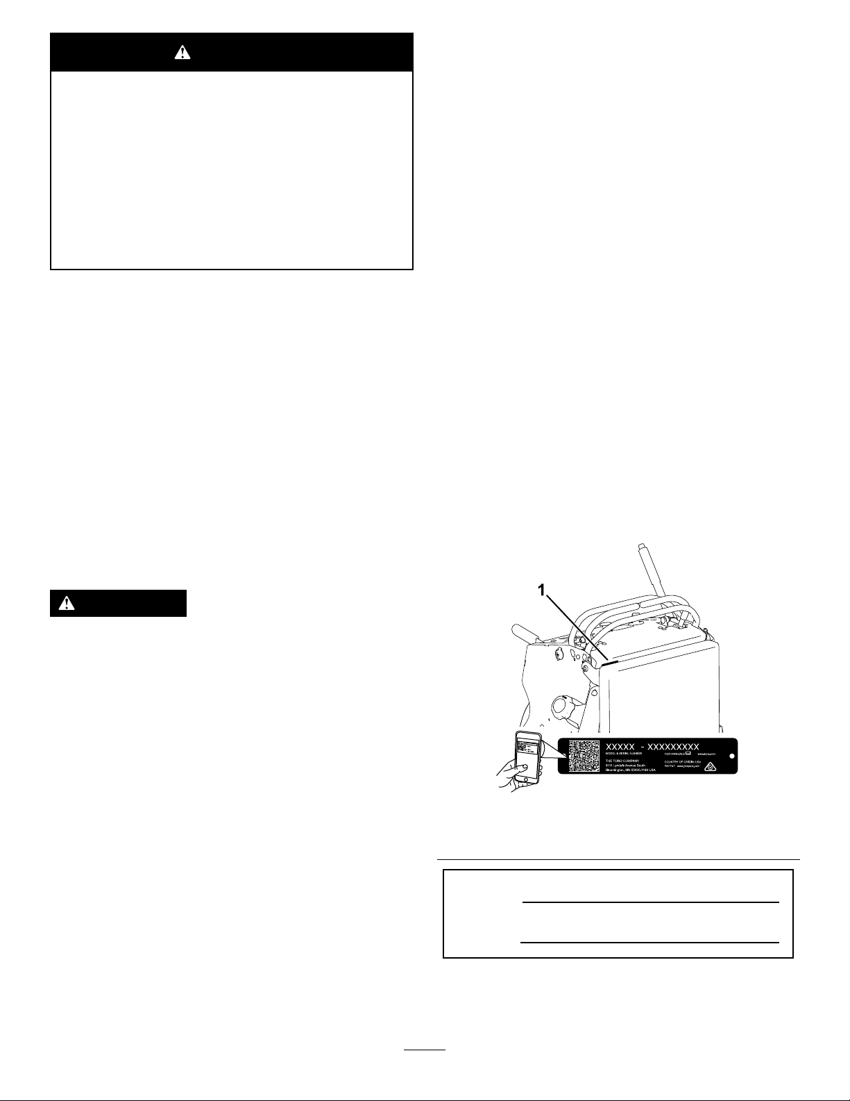
andserialnumbersofyourproductready.Figure1
identiesthelocationofthemodelandserialnumbers
ontheproduct.Writethenumbersinthespace
provided.
Important:Withyourmobiledevice,youcan
scantheQRcodeontheserialnumberdecal(if
equipped)toaccesswarranty,parts,andother
productinformation.
WARNING
Removingstandardoriginalequipmentparts
andaccessoriesmayalterthewarranty,
traction,andsafetyofthemachine.Failureto
useoriginalToropartscouldcauseserious
injuryordeath.Makingunauthorizedchanges
totheengine,fuelorventingsystem,may
violateEPAandCARBregulations.
Replaceallpartsincluding,butnotlimited
to,tires,belts,blades,andfuelsystem
componentswithoriginalToroparts.
g235457
Figure1
1.Locationofthemodelandserialnumbers
ModelNo.
SerialNo.
Thismanualidentiespotentialhazardsandhas
safetymessagesidentiedbythesafety-alertsymbol
(Figure2),whichsignalsahazardthatmaycause
©2017—TheToro®Company
8111LyndaleAvenueSouth
Bloomington,MN55420
Contactusatwww.Toro.com.
2
PrintedintheUSA
AllRightsReserved
Page 3

seriousinjuryordeathifyoudonotfollowthe
recommendedprecautions.
Figure2
1.Safety-alertsymbol
Thismanualuses2wordstohighlightinformation.
Importantcallsattentiontospecialmechanical
informationandNoteemphasizesgeneralinformation
worthyofspecialattention.
Contents
Safety.......................................................................4
SafeOperatingPractices....................................4
g000502
ToroMowerSafety..............................................6
SlopeIndicator...................................................8
SafetyandInstructionalDecals..........................9
ProductOverview...................................................13
Controls...........................................................13
Specications..................................................14
Operation................................................................15
ThinkSafetyFirst..............................................15
AddingFuel......................................................15
CheckingtheEngine-OilLevel..........................16
BreakinginaNewMachine..............................16
OperatingtheParkingBrake.............................17
OperatingtheMower-Blade-ControlSwitch
(PTO)............................................................17
OperatingtheThrottle.......................................17
OperatingtheIgnitionSwitch............................17
UsingtheFuel-ShutoffValve.............................18
StartingtheEngine...........................................18
ShuttingOfftheEngine.....................................19
TheSafety-InterlockSystem.............................19
OperatingthePlatform......................................20
DrivingForwardorBackward............................21
StoppingtheMachine.......................................22
PushingtheMachinebyHand..........................23
TransportingtheMachine.................................23
LoadingtheMachine........................................24
SideDischargingorMulchingthe
Grass............................................................25
AdjustingtheHeight-of-Cut...............................26
AdjustingtheAnti-ScalpRollers........................26
AdjustingtheFlowBafe..................................27
PositioningtheFlowBafe................................27
UsingtheMid-SizeWeight................................28
Maintenance...........................................................29
RecommendedMaintenanceSchedule(s)...........29
Pre-MaintenanceProcedures..............................30
ReleasingtheCushionforRearAccess............30
Lubrication..........................................................30
GreasingtheMachine.......................................30
GreasingtheT orsionIdler.................................30
GreasingtheFrontCasterPivots......................31
GreasingtheCaster-WheelHubs.....................31
GreasingtheMotionControls...........................32
EngineMaintenance...........................................32
ServicingtheAirCleaner..................................32
ServicingtheEngineOil....................................33
ServicingtheSparkPlug...................................36
CheckingtheSparkArrester.............................37
FuelSystemMaintenance...................................38
DrainingtheFuelT ank......................................38
RemovingtheFuelT ank...................................38
ServicingtheFuelFilter...................................39
ElectricalSystemMaintenance...........................39
ServicingtheBattery.........................................39
3
Page 4

ServicingtheFuses..........................................41
DriveSystemMaintenance..................................42
AdjustingtheTracking......................................42
CheckingtheTirePressure...............................42
AdjustingtheCaster-PivotBearing...................43
ServicingtheCasterWheelsand
Bearings........................................................43
RemovingtheClutchShim...............................44
CheckingtheWheel-LugNuts..........................45
CheckingtheWheel-HubNuts..........................45
CoolingSystemMaintenance..............................46
CleaningtheAir-IntakeScreen.........................46
CleaningtheCoolingSystem............................46
BrakeMaintenance.............................................46
ServicingtheBrake..........................................46
BeltMaintenance................................................47
ReplacingtheMower-DeckBelt........................47
ReplacingtheTransmissionBelt......................47
ControlsSystemMaintenance.............................48
AdjustingtheMotion-ControlLevers.................48
HydraulicSystemMaintenance...........................49
HydraulicSystemSpecications.......................49
CheckingtheHydraulicFluid............................49
ReplacingtheHydraulicFluidand
Filters............................................................50
BleedingtheHydraulicSystem.........................51
MowerDeckMaintenance....................................52
ServicingtheCuttingBlades.............................52
LevelingtheMowerDeck..................................54
AdjustingtheDeck-LiftSpring...........................56
ReplacingtheGrassDeector..........................56
Cleaning..............................................................57
CleaningundertheMower................................57
DisposingoftheWaste.....................................57
Storage...................................................................57
CleaningandStorage.......................................57
Troubleshooting......................................................59
Schematics.............................................................61
Safety
Improperuseormaintenancebytheoperatoror
ownercanresultininjury.T oreducethepotential
forinjury,complywiththesesafetyinstructions,
andpayattentiontothesafetyalertsymbol,which
meansCaution,Warning,orDanger—personalsafety
instruction.Failuretocomplywiththeinstructions
mayresultinpersonalinjuryordeath.
Thismachinewasmanufacturedaccordingtothe
appropriateregulatorystandardsineffectatthetime
ofmanufacture.Modifyingthismachineinanyway
maycauseittobeoutofcompliancewiththose
standardsandwiththeinstructionsinthisOperator’s
Manual.Modicationstothismachineshouldonly
bemadebyeitherthemanufactureroranAuthorized
ServiceDealer.
Thisproductiscapableofamputatinghandsandfeet.
Followallsafetyinstructionstoavoidseriousinjury
ordeath.
Theowner/usercanpreventandisresponsiblefor
accidentsorinjuriesoccurringtopeople,ordamage
toproperty.
Theadditionofattachmentsmadebyother
manufacturersthatdonotmeetAmericanNational
StandardsInstitutecerticationmaycause
noncomplianceofthismachine.
SafeOperatingPractices
ThefollowinginstructionsarefromANSIstandard
B71.4-2012.
Training
•ReadtheOperator'sManualandothertraining
material.Iftheoperator(s)ormechanic(s)cannot
readthemanuallanguage,itistheowner's
responsibilitytoexplainthismaterialtothem.
•Becomefamiliarwiththesafeoperationofthe
equipment,operatorcontrols,andsafetysigns.
•Alloperatorsandmechanicsshouldbetrained.
Theownerisresponsiblefortrainingtheusers.
•Neverletchildrenoruntrainedpeopleoperateor
servicetheequipment.Localregulationsmay
restricttheageoftheoperator.
•Theowner/usercanpreventandisresponsible
foraccidentsorinjuriesoccurringtohimselfor
herself,otherpeople,ordamagetoproperty.
4
Page 5

Preparation
•Evaluatetheterraintodeterminewhataccessories
andattachmentsyouneedtoproperlyandsafely
performthejob.Useonlyaccessoriesand
attachmentsapprovedbythemanufacturer.
•Wearappropriateclothing;includingsafety
glasses,longpants,substantialslip-resistant
footwear,gloves,andhearingprotection.Tieback
longhair.Donotwearjewelry.
•Inspecttheareawhereyouwillusetheequipment
andensurethatallobjectsareremovedfromthe
areabeforeuse.
•Useextracarewhenhandlingfuels.Theyare
ammableandvaporsareexplosive.
–Useonlyanapprovedcontainer.
–Donotremovethefuelcaporaddfuelwiththe
enginerunning.Allowtheenginetocoolbefore
refueling.Donotsmokenearthemachine
whentheengineisrunning.
–Donotrefuelordrainthemachineindoors.
•Checkthattheoperator'spresencecontrols,safety
switches,andshieldsareattachedandfunctioning
properly.Donotoperatethemachineunlessthey
arefunctioningproperly.
Operation
•Lightningcancausesevereinjuryordeath.If
lightningisseen,orthunderisheardinthearea,
donotoperatethemachine;seekshelter.
•Donotrunanengineinanenclosedarea.
•Operateonlyinwell-litareas,keepingawayfrom
holesandhiddenhazards.
•Ensurethatalldrivesareinneutralandthatthe
parkingbrakeisengagedbeforestartingengine.
Starttheengineonlyfromtheoperator’sposition.
•Makesurethatyouhavegoodfootingwhile
usingthismachine,especiallywhenbackingup.
Reducedfootingcouldcauseslipping.
•Slowdownanduseextracareonhillsides.Be
suretotravelsidetosideonhillsides.Turf
conditionscanaffectthestabilityofthemachine.
Usecautionwhileoperatingneardrop-offs.
•Slowdownandusecautionwhenmakingturns
andwhenchangingdirectionsonslopes.
•Donotraisethemowerdeckwiththeblades
running.
•DonotoperatethemachinewithoutthePTO
shieldorotherguardssecurelyinplace.Besure
thatallinterlocksareattached,adjustedproperly,
andfunctioningproperly.
•Donotoperatewiththedischargedeectorraised,
removedoraltered,unlessyouareusingagrass
catcher.
•Donotchangetheenginegovernorsettingor
overspeedtheengine.
•Stoponlevelground,disengagedrives,engage
theparkingbrake,shutofftheenginebefore
leavingtheoperator'spositionforanyreason,
includingemptyingthecatchersoruncloggingthe
chute.
•Stopequipmentandinspectthebladesafter
strikingobjectsorifanabnormalvibrationoccurs.
Makethenecessaryrepairsbeforeresuming
operations.
•Keepyourhandsandfeetawayfromthecutting
unit.
•Lookbehindanddownbeforebackingupto
ensureaclearpath.
•Keeppetsandbystandersawayfromanoperating
machine.
•Slowdownandusecautionwhenmakingturns
andcrossingroadsandsidewalks.Stopthe
bladesifyouarenotmowing.
•Beawareofthemower-dischargedirectionand
donotpointitatanyone.
•Donotoperatethemachinewhiletired,ill,or
undertheinuenceofalcoholordrugs.
•Usecarewhenloadingorunloadingthemachine
intoorfromatrailerortruck.
•Usecarewhenapproachingblindcorners,shrubs,
trees,orotherobjectsthatmayobscurevision.
SafeHandlingofFuels
•Toavoidpersonalinjuryorpropertydamage,use
extremecareinhandlinggasoline.Gasolineis
extremelyammableandthevaporsareexplosive.
•Extinguishallcigarettes,cigars,pipes,andother
sourcesofignition.
•Useonlyanapprovedfuelcontainer.
•Donotremovethefuelcaporaddfuelwiththe
enginerunning.
•Allowtheenginetocoolbeforefueling.
•Donotfuelthemachineindoors.
•Donotstorethemachineorfuelcontainerwhere
thereisanopename,spark,orpilotlight,such
asonawaterheateroronotherappliances.
•Donotllcontainersinsideavehicle,onatruck,
oronatrailerbedwithaplasticliner.Alwaysplace
containersonthegroundawayfromyourvehicle
beforelling.
•Removeequipmentfromthetruckortrailerand
fuelitontheground.Ifthisisnotpossible,
thenaddfuelwithsuchequipmentasaportable
containerratherthanfromafuel-dispensernozzle.
5
Page 6

•Keepthenozzleincontactwiththerimofthefuel
tankorcontaineropeningatalltimesuntilfueling
iscomplete.Donotuseanozzlelock-opendevice.
•Ifyouspillfuelonclothing,changeyourclothing
immediately.
•Donotoverllthefueltank.Replacethefuelcap
andtightenitsecurely.
ToroMowerSafety
Thefollowinglistcontainssafetyinformationspecic
toT oroproductsandothersafetyinformationthatyou
mustknow.
Thisproductiscapableofamputatinghandsand
feetandofthrowingobjects.Alwaysfollowallsafety
instructionstoavoidseriousinjuryordeath.
MaintenanceandStorage
•Disengagedrives,settheparkingbrake,shutoff
theengine,andremovethekeyordisconnect
spark-plugwire.Waitforallmovementtostop
beforeadjusting,cleaning,orrepairing.
•Cleangrassanddebrisfromthecuttingunit,
drives,mufers,andenginetohelppreventres.
•Cleanupoilorfuelspills.
•Lettheenginecoolbeforestoringthemachine.
•Donotstorefuelnearamesordrainthefuel
indoors.
•Donotallowuntrainedpersonneltoservicethe
machine.
•Usejackstandstosupportcomponentswhen
required.
•Carefullyreleasepressurefromcomponentswith
storedenergy.
•Disconnectthebatteryorremovethespark-plug
wirebeforemakinganyrepairs.Disconnectthe
negativeterminalrstandthepositiveterminal
last.Connectthepositiveterminalrstand
negativelast.
•Usecarewhencheckingtheblades.Wrapthe
blade(s)orweargloves,andusecautionwhen
servicingthem.Onlyreplaceblades;donot
straightenorweldthem.
•Keephandsandfeetawayfrommovingparts.If
possible,donotmakeadjustmentswiththeengine
running.
•Keepallpartsingoodworkingconditionandall
hardwaretightened.Replaceallwornordamaged
decals.
Thisproductisdesignedforcuttingandrecycling
grass,or,whenequippedwithagrassbagger,for
catchingcutgrass.Anyuseforpurposesother
thanthesecouldprovedangeroustotheuserand
bystanders.
GeneralOperation
•Besurethattheareaisclearofbystandersbefore
mowing.Stopthemachineifanyoneentersthe
area.
•Donottouchequipmentorattachmentpartswhich
maybehotfromoperation.Allowalltheparts
tocoolbeforeattemptingtomaintain,adjust,or
servicethemachine.
•UseonlyToro-approvedattachments.Warranty
maybevoidedifusedwithanyunapproved
attachments.
•Checkcarefullyforoverheadclearances(i.e.,
branches,doorways,electricalwires,etc.)before
operatingunderanyobjects,anddonotcontact
them.
•Slowdownbeforemakingturnsanduseextra
caution.
•Usecautionwhenridingtheplatformovercurbs,
rocks,roots,orotherobstructions.
•Lookbehindanddownbeforebackinguptoensure
aclearpath.Useextracarewhenoperatingthe
machineinreverse.
•Donotjerkthecontrols;useasteadymotion.
•Whenloadingorunloadingthemachine,use1
full-widthrampthatiswideenoughtoextend
beyondthewidthofthemachine.
•Donotcarrypassengers.
Hauling
•Usecarewhenloadingorunloadingthemachine
intoatraileroratruck.
•Usefull-widthrampsforloadingmachineintoa
traileroratruck.
•Tiethemachinedownsecurelyusingstraps,
chains,cable,orropes.Bothfrontandrearstraps
shouldbedirecteddownandoutwardfromthe
machine.
•Donotcarryequipmentonthemachine.
6
Page 7

SlopeOperation
Allslopesandrampsrequireextracaution.Ifyoufeel
uneasyonaslope,donotmowit.
•Removeobstaclessuchasrocks,treelimbs,etc.
fromthemowingarea.
•Watchforholes,rutsorbumps.T allgrasscan
hideobstacles.
•Usecautionneardrop-offs,ditches,or
embankments.Themachinecouldsuddenlyturn
overifawheelgoesovertheedgeofacliffor
ditch,orifanedgecavesin.
•Useextracarewithgrasscatchersorother
attachments.Thesecanchangethestabilityof
themachine.
•Keepallmovementonslopesslowandgradual.
•Donotmakesuddenchangesinspeedor
direction.
•Mowslopessidetoside.
•Donotmowslopesgreaterthan20degrees.
Service
•Donotstorethemachineorafuelcontainerinside
wherethereisanopename,suchasneara
waterheaterorfurnace.
•Keepthenutsandboltstight,especiallythe
blade-attachmentbolts.
•Neverremoveortamperwithsafetydevices.
Checktheirproperoperationregularly.Neverdo
anythingtointerferewiththeintendedfunctionofa
safetydeviceortoreducetheprotectionprovided
byasafetydevice.
•Tobestprotectyourinvestmentandmaintain
optimalperformanceofyourToroequipment,count
onT orogenuineparts.Whenitcomestoreliability,
Torodeliversreplacementpartsdesignedtothe
exactengineeringspecicationsofourequipment.
Forpeaceofmind,insistonT orogenuineparts.
•Checktheoperationofthebrakesfrequently.
Adjustandservicethemasrequired.
7
Page 8
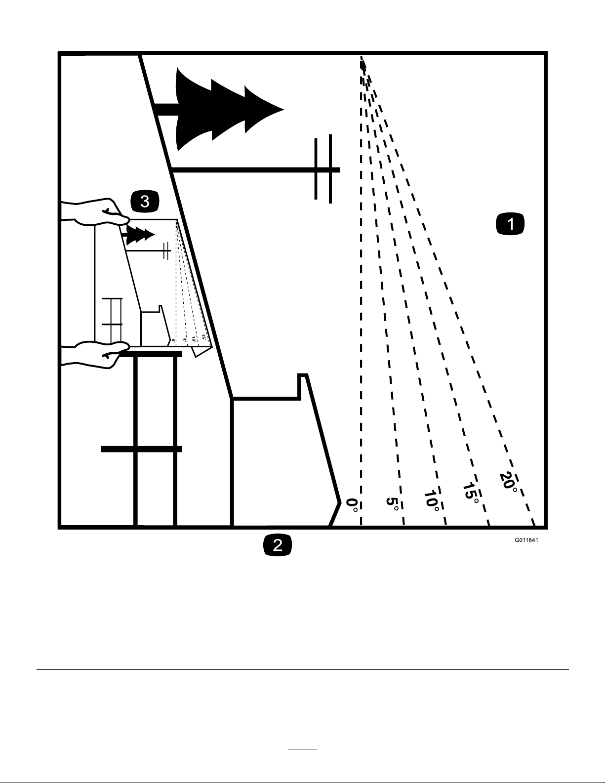
SlopeIndicator
Figure3
Thispagemaybecopiedforpersonaluse.
1.Themaximumslopeyoucanoperatethemachineonis15degrees.Usetheslopecharttodeterminethedegreeofslopeof
hillsbeforeoperating.Donotoperatethismachineonaslopegreaterthan15degrees.Foldalongtheappropriateline
tomatchtherecommendedslope.
2.Alignthisedgewithaverticalsurface,atree,building,fencepole,etc.
3.Exampleofhowtocompareslopewithfoldededge
8
g011841
Page 9
SafetyandInstructionalDecals
Safetydecalsandinstructionsareeasilyvisibletotheoperatorandarelocatednearanyarea
ofpotentialdanger.Replaceanydecalthatisdamagedormissing.
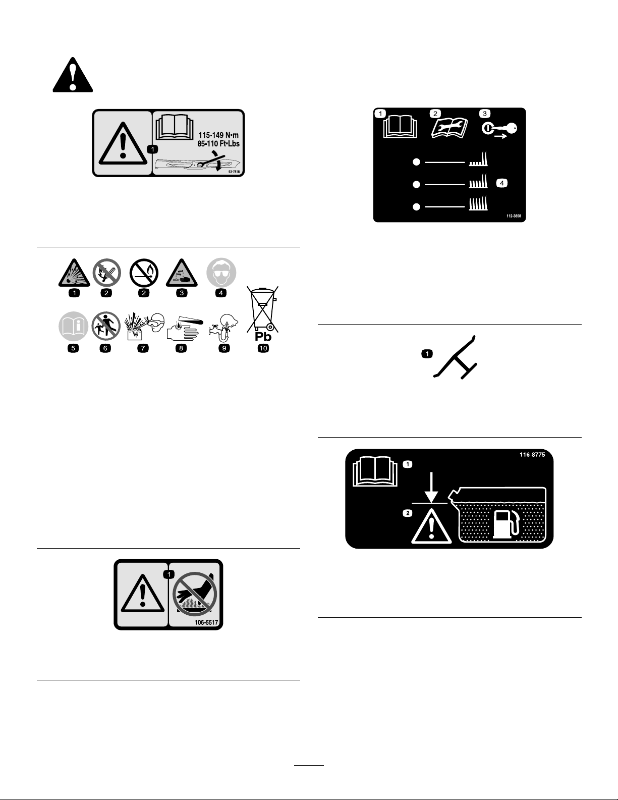
93-7818
1.Warning—readtheOperator'sManualforinstructionson
torquingthebladebolt/nutto1 15to149N∙m(85to110
ft-lb).
decal93-7818
decal112-3858
112-3858
BatterySymbols
Someorallofthesesymbolsareonyourbattery
1.Explosionhazard
2.Nore,opename,or
smoking.
3.Causticliquid/chemical
burnhazard
4.Weareyeprotection.9.Flusheyesimmediately
5.ReadtheOperator's
Manual.
6.Keepbystandersasafe
7.Weareyeprotection;
8.Batteryacidcancause
10.Containslead;donot
decalbatterysymbols
distancefromthebattery.
explosivegasescan
causeblindnessandother
injuries.
blindnessorsevereburns.
withwaterandgetmedical
helpfast.
discard.
1.ReadtheOperator's
Manual.
3.Removetheignitionkey
beforeadjustingtheheight
ofcut.
2.Readtheinstructions
4.Height-of-cutsettings.
beforeservicingor
performingmaintenance.
Manufacturer'sMark
1.Indicatesthebladeisidentiedasapartfromtheoriginal
machinemanufacturer.
decaloemmarkt
1.Warning—donottouchthehotsurface.
decal116-8775
116-8775
1.ReadtheOperator’s
Manual.
decal106-5517
2.Filltobottomofllerneck;
warning—donotoverll
thetank.
106-5517
9
Page 10

decal133-4604
133-4604
1.Thrownobject
hazard—keepbystanders
awayfromthemachine.
2.Thrownobjecthazard,
openbafe—onlyoperate
themachinewithabafe
oragrasscollector.
3.Severinghazardofhand
orfoot—keepawayfrom
movingparts.
4.Entanglement
hazard—keepaway
frommovingparts;keep
allguardsandshieldsin
place.
1.ReadtheOperator's
1.Height-of-cut
decal131-3507
131-3507
2.Belttensioner
Manual.
decal131-3521
131-3521
131-1180
1.ReadtheOperator'sManual.(A)Short,lightgrass;dry
conditions;maximumdispersion;(B)Baggingsetting;(C)
Tall,densegrass;wetconditions;maximumgroundspeed
decal131-1180
1.ReadtheOperator's
2.Transmissionoil
10
decal131-3524
131-3524
3.Oillevel
Manual.
Page 11
131-3528
15A 15A 10A
7.5A
decal131-3528
131-3528
1.Ingition—15A
2.Accessoryport—15A
3.Powertakeoff(PTO)—10
4.Infocenter—7.5A
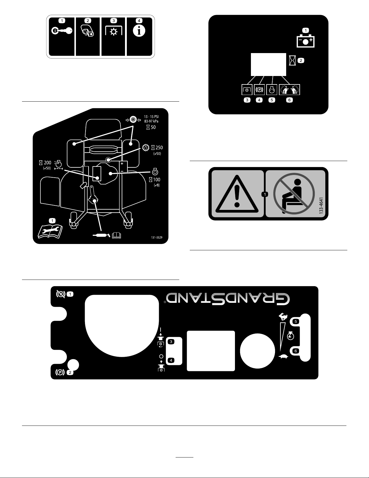
131-3529
A
decal131-3536
131-3536
1.Battery4.Parkingbrake
2.Time5.Engine—start
3.Powertakeoff(PTO)
6.Engagethehandlebars.
decal133-4641
133-4641
decal131-3529
1.Warning—donotcarryanypassengers.
1.ReadtheOperator'sManualformoreinformationon
maintenanceintervalsandprocedures.
1.Engagetheparkingbrake.
2.Disengagetheparkingbrake.
3.PulluptoturnonthePTO.
decal130-1790
130-1790
4.PushdowntoturnoffthePTO.
5.Enginespeed—fast
6.Enginespeed—slow
11
Page 12
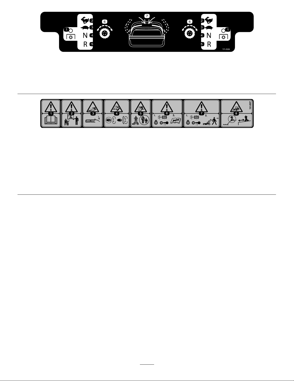
decal131-3526
131-3526
1.Powertakeoff(PTO)—disengaged
5.Reverse
2.Fast6.Tractiondrive
3.Slow
7.Engagethehandles.
4.Neutral
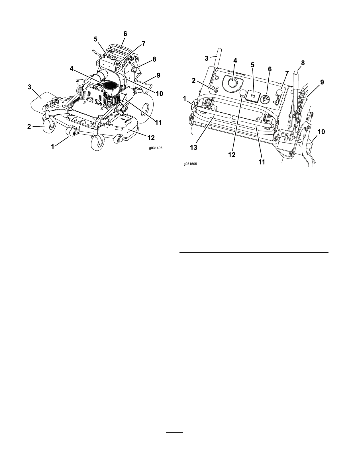
131-3527
1.Warning—readtheOperator'sManual.5.Thrownobjecthazard—keepbystandersawayfromthe
2.Warning—receivetrainingbeforeoperatingthemachine.6.Warning—1)Engagetheparkingbrake,shutofftheengine,
3.Thrownobjecthazard—keepthedeectorloweredduring
operation.
4.Cutting/severinghazardofhandorfoot—keepawayfrom
movingparts;keepallguardsandshieldsinplace.
machine.
andremovethekeyfromtheignition;2)ReadtheOperator's
Manualbeforeservicingorperformingmaintenance.
7.Warning—engagetheparkingbrake,shutofftheengine,and
removethekeyfromtheignitionbeforeleavingthemachine.
8.Tippinghazard—donotoperateneardrop-offsornearwater.
decal131-3527
12
Page 13
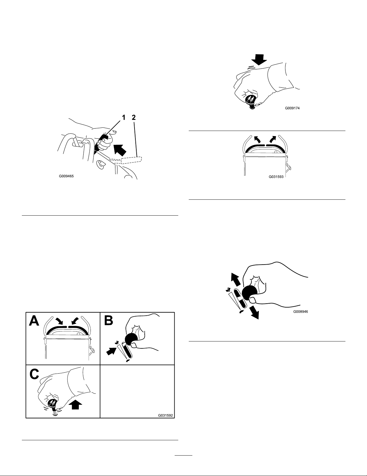
ProductOverview
Figure4
1.Anti-scalproller(60-inch
decksonly)
2.Frontcasterwheel8.Fueltank
3.Side-dischargechute9.Platform(downposition)
4.Engine
5.Controls
6.Controllevers
7.Hydraulictank
10.Fuel-shutoffvalve
11.Battery
12.Mowerdeck
Controls
Becomefamiliarwithallthecontrolsbeforeyoustart
theengineandoperatethemachine(Figure5).
g031496
g031505
Figure5
1.Fuelcap
2.Malfunction-indicatorlight
(MIL)
3.Parking-brakelever
4.Hydraulic-tankcap11.Rightmotion-controllever
5.Hourmeter12.Blade-controlswitch
6.Ignitionswitch
7.Throttlecontrol
8.Height-of-cutlever
9.Height-of-cutpin
10.Platformlatch
(PTO)
13.Leftmotion-controllever
Electronic-ControlUnit
Malfunction-IndicatorLight
Theelectronic-controlunit(ECU)continuously
monitorstheoperationoftheEFIsystem.
Ifaproblemorfaultwithinthesystemisdetected,the
malfunction-indicatorlight(MIL)isilluminated(Figure
5).
TheMIListheredlightlocatedintheconsolepanel.
WhentheMILilluminates,makeinitialtroubleshooting
checks.
Ifthesechecksdonotcorrecttheproblem,further
diagnosisandservicingbyanAuthorizedService
Dealerisnecessary.
HourMeter
Thehourmeterrecordsthenumberofhoursthe
enginehasoperated.Itoperateswhentheengine
13
Page 14

isrunning.Usethesetimesforschedulingregular
maintenance(Figure5).
Safety-InterlockIndicators
Symbolsonthehourmeterindicatewithablack
trianglethattheinterlockcomponentisinthecorrect
position(Figure5).
Specications
Note:Specicationsanddesignaresubjectto
changewithoutnotice.
48-inchMowers
Widthwithdeectordown161cm(64inches)
Widthwithdeectorraised126cm(50inches)
Battery-IndicatorLight
IftheignitionkeyisturnedtotheONpositionfora
fewseconds,thebatteryvoltagedisplaysinthearea
wherethehoursarenormallydisplayed.
Thebatterylightturnsonwhentheignitionisturned
onandwhenthechargeisbelowthecorrectoperating
level(Figure5).
ThrottleControl
ThethrottlecontrolisvariablebetweenFastand
Slow(Figure5).
Blade-ControlSwitch(PTO)
Usetheblade-controlswitch(PTO)toengageand
disengagethemowerblades(Figure5).
IgnitionSwitch
Usetheignitionswitchtostartthemowerengine
(Figure5).Theswitchhas3positions:OFF,RUN,
andSTART.
Lengthwithplatformdown191cm(75inches)
Lengthwithplatformup145cm(61inches)
Height
WeightforModel74518and
74918
122cm(48inches)
407kg(899lb)
52-inchMowers
Widthwithdeectordown172cm(68inches)
Widthwithdeectorraised137cm(54inches)
Lengthwithplatformdown191cm(75inches)
Lengthwithplatformup145cm(61inches)
Height
WeightforModel74519412kg(908lb)
122cm(48inches)
60-inchMower
Widthwithdeectordown193cm(76inches)
Widthwithdeectorraised158cm(62inches)
Motion-ControlLevers
Themotion-controlleversareusedtodrivethe
machineforwardandreverseandtoturneither
direction(Figure5).
Fuel-ShutoffValve
Closethefuel-shutoffvalve(locatedontheleftsideof
thefueltank)whentransportingorstoringthemower
(Figure4).
Attachments/Accessories
AselectionofT oroapprovedattachmentsand
accessoriesisavailableforusewiththemachineto
enhanceandexpanditscapabilities.Contactyour
AuthorizedServiceDealerorDistributororgoto
www.T oro.comforalistofallapprovedattachments
andaccessories.
Lengthwithplatformdown201cm(79inches)
Lengthwithplatformup164cm(65inches)
Height
WeightforModel74513419kg(924lb)
122cm(48inches)
14
Page 15

Operation
Note:Determinetheleftandrightsidesofthe
machinefromthenormaloperatingposition.
DANGER
Incertainconditions,fuelisextremely
ammableandhighlyexplosive.Areor
explosionfromfuelcanburnyouandothers
andcandamageproperty.
ThinkSafetyFirst
Carefullyreadallthesafetyinstructionsanddecals
inthesafetysection.Knowingthisinformationcould
helpyouorbystandersavoidinjury.
CAUTION
Thismachineproducessoundlevelsin
excessof85dBAattheoperator'searand
cancausehearinglossfromextendedperiods
ofexposure.
Wearhearingprotectionwhenoperatingthis
machine.
Figure6
1.Wearhearingprotection.
•Fillthefueltankoutdoors,inanopenarea,
whentheengineiscold.Wipeupanyfuel
thatspills.
•Neverllthefueltankinsideanenclosed
trailer.
•Donotllthefueltankcompletelyfull.
Addfueltothefueltankuntilthelevelis6
to13mm(1/4to1/2inch)belowthebottom
ofthellerneck.Thisemptyspaceinthe
tankallowsfueltoexpand.
•Neversmokewhenhandlingfuel,andstay
awayfromanopenameorwherefuel
fumesmaybeignitedbyaspark.
•Storefuelinanapprovedcontainerand
keepitoutofthereachofchildren.Never
buymorethana30-daysupplyoffuel.
•Donotoperatewithoutentireexhaust
g229846
systeminplaceandinproperworking
condition.
AddingFuel
•Forbestresults,useonlyclean,fresh(lessthan
30daysold),unleadedgasolinewithanoctane
ratingof87orhigher((R+M)/2ratingmethod).
•Ethanol:Gasolinewithupto10%ethanol
(gasohol)or15%MTBE(methyltertiarybutyl
ether)byvolumeisacceptable.Ethanoland
MTBEarenotthesame.Gasolinewith15%
ethanol(E15)byvolumeisnotapprovedforuse.
Neverusegasolinethatcontainsmorethan
10%ethanolbyvolume,suchasE15(contains
15%ethanol),E20(contains20%ethanol),orE85
(containsupto85%ethanol).Usingunapproved
gasolinemaycauseperformanceproblemsand/or
enginedamagethatmaynotbecoveredunder
warranty.
•Donotusegasolinecontainingmethanol.
•Donotstorefueleitherinthefueltankorfuel
containersoverthewinterunlessyouuseafuel
stabilizer.
•Donotaddoiltogasoline.
15
Page 16

DANGER
Incertainconditionsduringfueling,static
electricitycanbereleasedcausingaspark,
whichcanignitethefuelvapors.Areor
explosionfromfuelcanburnyouandothers
andcandamageproperty.
Addthecorrectamountoffuelstabilizer/conditioner
tothefuel.
Note:Afuelstabilizer/conditionerismost
effectivewhenmixedwithfreshfuel.Tominimize
thechanceofvarnishdepositsinthefuelsystem,
usefuelstabilizeratalltimes.
•Alwaysplacefuelcontainersontheground
awayfromyourvehiclebeforelling.
•Donotllfuelcontainersinsideavehicle
oronatruckortrailerbedbecauseinterior
carpetsorplastictruckbedlinersmay
insulatethecontainerandslowthelossof
anystaticcharge.
•Whenpractical,removegas-powered
equipmentfromthetruckortrailerand
refueltheequipmentwithitswheelsonthe
ground.
•Ifthisisnotpossible,thenrefuelsuch
equipmentonatruckortrailerfroma
portablecontainerratherthanfroma
fuel-dispensernozzle.
•Ifyoumustuseafuel-dispensernozzle,
keepthenozzleincontactwiththerimof
thefueltankorcontaineropeningatall
timesuntilfuelingiscomplete.
FillingtheFuelTank
1.Parkthemachineonalevelsurface,disengage
thePTO,movethemotion-controlleverstothe
NEUTRAL-LOCKposition,andengagetheparking
brake.
2.Shutofftheengine,removethekey,andwait
forallmovingpartstostopbeforeleavingthe
operatingposition.
3.Cleanaroundthefuel-tankcapandremovethe
cap.
4.Fillthefueltanktothebottomofthellerneck.
Note:Donotllthefueltankcompletelyfull.
Theemptyspaceinthetankallowsthegasoline
toexpand.
5.Installthefuel-tankcapsecurely.Wipeupany
spilledfuel.
CheckingtheEngine-Oil Level
WARNING
Fuelisharmfulorfatalifswallowed.
Long-termexposuretovaporscancause
seriousinjuryandillness.
•Avoidprolongedbreathingofvapors.
•Keepyourfaceawayfromthenozzleand
fueltankorconditionerbottleopening.
•Avoidcontactwithskin;washoffspills
withsoapandwater.
UsingStabilizer/Conditioner
Useafuelstabilizer/conditionerinthemachineto
providethefollowingbenets:
•Keepsfuelfreshduringstorageof90daysorless.
Forlongerstorage,drainthefueltank.
•Cleanstheenginewhileitruns
•Eliminatesgum-likevarnishbuildupinthefuel
system,whichcauseshardstarting
Important:Donotusefueladditives
containingmethanolorethanol.
Beforeyoustarttheengineandusethemachine,
checktheoillevelintheenginecrankcase;referto
CheckingtheEngine-OilLevel(page34).
BreakinginaNewMachine
Newenginestaketimetodevelopfullpower.Mower
decksanddrivesystemshavehigherfrictionwhen
new,placingadditionalloadontheengine.Allow
40to50hoursofbreak-intimefornewmachinesto
developfullpowerandbestperformance.
16
Page 17
OperatingtheParking Brake
Alwaysengagetheparkingbrakewhenyoushutoff
themachineorleaveitunattended.Beforeeachuse,
checktheparkingbrakeforproperoperation.
Iftheparkingbrakedoesnotholdsecurely,adjustit;
refertoAdjustingtheBrakes(page46).
Pulltheparking-brakeleverrearwardtoengageit
(Figure7).
DisengagingtheMowerBlades (PTO)
Figure9andFigure10show2waystodisengage
themowerblades.
Pushtheparking-brakeleverforwardtodisengageit.
Figure7
1.Parkingbrake—engaged2.Parking
brake—disengaged
Operatingthe Mower-Blade-Control Switch(PTO)
Usetheblade-controlswitch(PTO)inconjunctionwith
themotion-controlleverstoengageanddisengage
themowerblades.
g009174
Figure9
g009465
Figure10
g031593
OperatingtheThrottle
ThethrottlecontrolmovesbetweenFASTandSLOW
positions(Figure11).
AlwaysusetheFASTpositionwhenengagingthe
mowerbladeswiththeblade-controlswitch(PTO).
EngagingtheMowerBlades(PTO)
Figure8
g008946
Figure11
OperatingtheIgnition Switch
Important:Donotengagethestarterformore
than5secondsatatime.Iftheenginefailsto
start,wait15secondsbetweenattempts.Failure
tofollowtheseinstructionscanburnoutthe
startermotor.
g031592
Note:Youmayneedtorepeatthecycleforstarting
theenginewhenyoustartitforthersttimeafteryou
havelledacompletelyemptyfuelsystemwithfuel.
17
Page 18
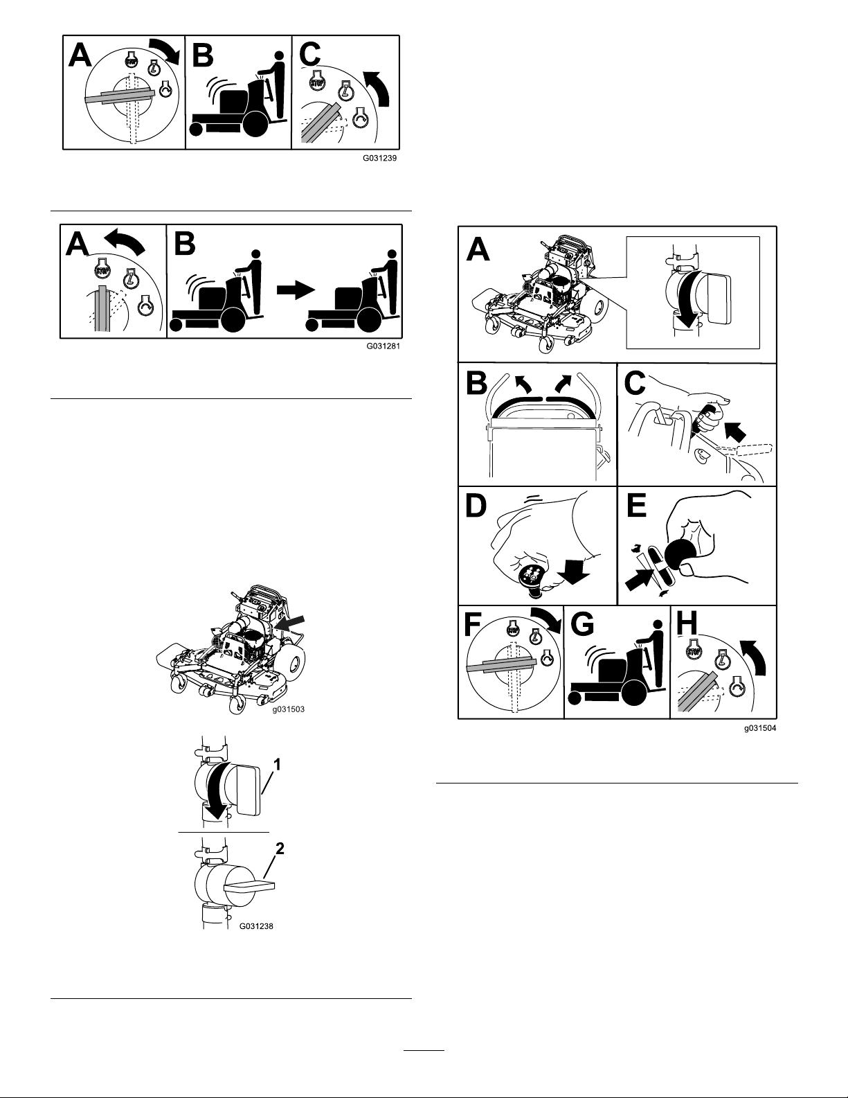
StartingtheEngine
Important:Donotengagethestarterformore
than5secondsatatime.Iftheenginefailsto
start,wait15secondsbetweenattempts.Failure
tofollowtheseinstructionscanburnoutthe
startermotor.
g031239
Figure12
g031281
Figure13
Note:Youmayneedtorepeatthecycleforstarting
theenginewhenyoustartitforthersttimeafteryou
havelledacompletelyemptyfuelsystemwithfuel.
UsingtheFuel-Shutoff Valve
Closethefuel-shutoffvalvefortransport,maintenance,
andstorage(Figure14).
Ensurethatthefuel-shutoffvalveisopenwhen
startingtheengine.
g031503
g031504
Figure15
Figure14
1.ONposition2.OFFposition
g031238
18
Page 19
ShuttingOfftheEngine
CAUTION
TheSafety-Interlock System
Childrenorbystandersmaybeinjuredifthey
moveorattempttooperatethemachinewhile
itisunattended.
Alwaysremovethekeyandengagethe
parkingbrakewhenleavingthemachine
unattended.
Lettheengineidleatslowthrottle(turtle)for60
secondsbeforeturningthekeyswitchtotheOFF
position.
CAUTION
Ifthesafety-interlockswitchesare
disconnectedordamaged,themachinecould
operateunexpectedly,causingpersonal
injury.
•Donottamperwiththeinterlockswitches.
•Checktheoperationoftheinterlock
switchesdailyandreplaceanydamaged
switchesbeforeoperatingthemachine.
Understandingthe Safety-InterlockSystem
Thesafety-interlocksystemisdesignedtoprevent
themowerbladesfromrotatingunlessyoudo1of
thefollowing:
•Moveeithermotion-controllevertothecenter,
unlockedposition.
•Pulltheblade-controlswitch(PTO)totheON
position.
Figure16
Important:Makesurethatthefuel-shutoffvalve
isclosedbeforetransportingorstoringthe
machinetopreventafuelleak.Beforestoringthe
machine,disconnectthesparkplug(s)toprevent
thepossibilityofaccidentalstarting.
Thesafety-interlocksystemisdesignedtostop
themowerbladesifyoumoveorreleaseboth
motion-controlleversintotheNEUTRAL-LOCK
position.
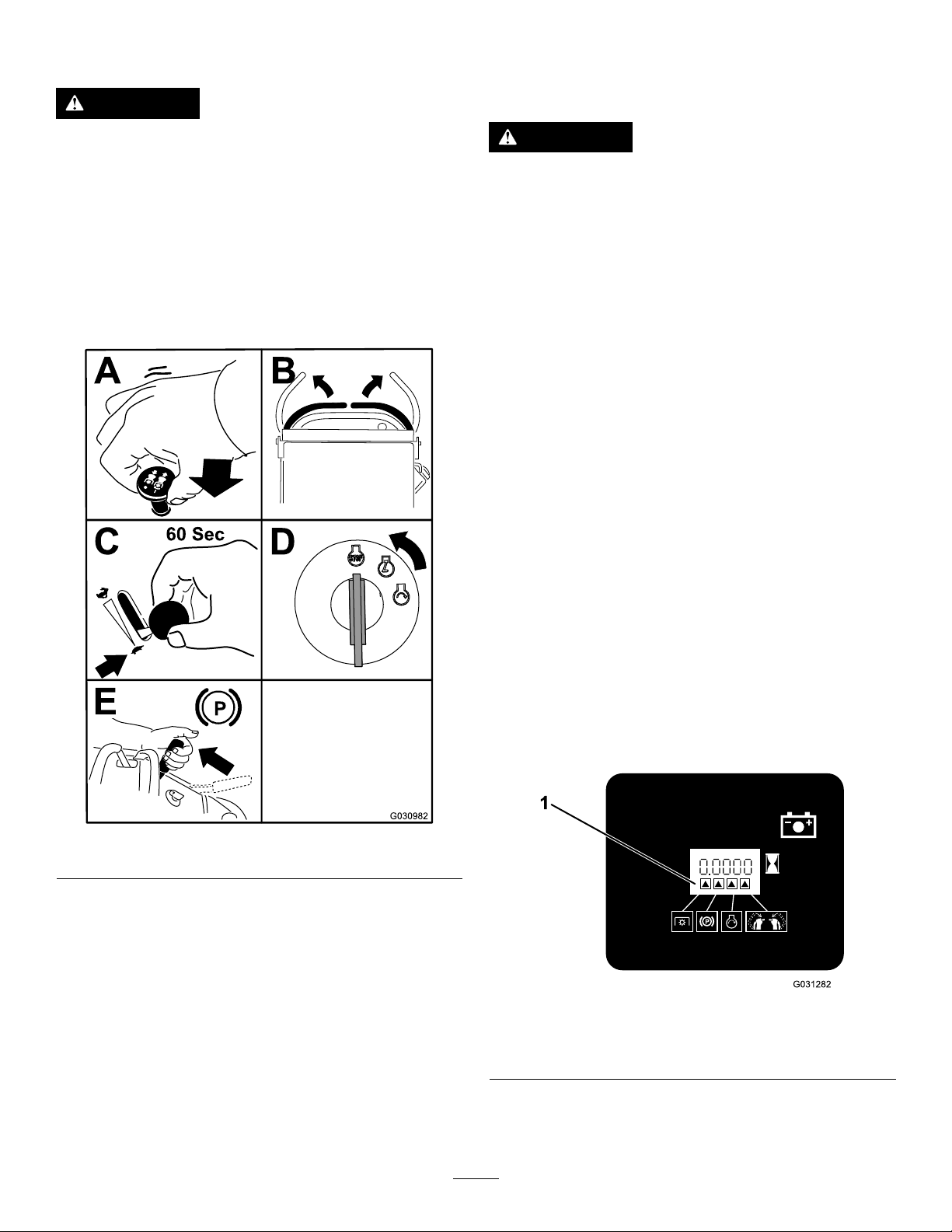
Thehourmeterhassymbolstonotifytheuser
wheneachinterlockcomponentisinthecorrect
position.Whenthecomponentisinthecorrect
position,atrianglelightsupinthecorresponding
square(Figure17).
g030982
g031282
Figure17
1.Triangleslightupwhentheinterlockcomponentsareinthe
correctposition.
19
Page 20

TestingtheSafety-Interlock System
ServiceInterval:Beforeeachuseordaily
Testthesafety-interlocksystembeforeyouusethe
machineeachtime.
Note:Ifthesafetysystemdoesnotoperateas
describedbelow,haveanAuthorizedServiceDealer
repairthesafetysystemimmediately.
1.Starttheengine;refertoStartingtheEngine
(page18).
2.Movethemotion-controlleverstothecenter,
unlockedposition.
Note:Thebladesshouldnotrotateandthe
engineshouldstoprunning.
3.Starttheengineandreleasetheparkingbrake.
4.Moveeithermotion-controllevertothecenter,
unlockedposition.
5.Continueholdingthemotion-controlleverin
thecenter,unlockedposition,pulluponthe
blade-controlswitch(PTO),andreleasethe
switch.
WARNING
Theoperatorplatformisheavyandmaycause
injurywhenloweringandraisingtheoperator
platform.Carefullylowerorraisetheoperator
platform,assuddenlydroppingitcouldinjure
you.
•Donotputyourhandsorngersinthe
platform-pivotareawhenloweringor
raisingtheoperatorplatform.
•Makesurethattheplatformissupported
whenyoupullthelatchpinout.
•Makesurethatthelatchsecuresthe
platformwhenfoldingitup.Pushittight
againstthecushionforthelatchpinto
lockintoplace.
•Keepbystandersawaywhenraisingor
loweringtheplatform.
OperatingthePlatform
Youcanusethemachinewiththeplatforminthe
upordownposition.Itisyourpreferenceonwhich
positiontouse.
Note:Theclutchshouldengageandthemower
bladesrotate.
6.Moveorreleasethemotion-controlleversinto
theNEUTRAL-LOCKposition.
Note:Thebladesshouldstoprotatingandthe
engineshouldcontinuetorun.
7.Pushtheblade-controlswitchdownand
moveeithermotion-controllevertothecenter,
unlockedposition.
8.Continueholdingthemotion-controlleverin
thecenter,unlockedposition,pulluponthe
blade-controlswitch(PTO),andreleasethe
switch.
Note:Theclutchshouldengageandthemower
bladesshouldrotate.
9.Pushtheblade-controlswitch(PTO)downto
theOFFposition.
Note:Thebladesshouldstoprotating.
10.Withtheenginerunning,pulluptheblade-control
switch(PTO)andreleaseitwithoutholding
eithermotion-controllevertothecenter,
unlockedposition.
Note:Thebladesshouldnotrotate.
OperatingtheMachinewiththe PlatformUp
Operatethemachinewiththeplatformupforthe
followingconditions:
•Mowingneardrop-offs
•Mowingsmallareaswherethemachineistoo
large
•Areaswithlow,over-hangingbranchesor
obstacles
•Loadingthemachinefortransport
•Drivingupslopes
Toraisetheplatform,pullthebackoftheplatformup
sothatthelatchpinandknoblockitintoplace.Push
ittightagainstthecushionforthelatchpintolockit
intoplace.
OperatingtheMachinewiththe PlatformDown
Operatethemachinewiththeplatformdownforthe
followingconditions:
•Mowingmostareas
•Drivingacrossslopes
•Drivingdownslopes
Tolowertheplatform,pushtheplatformforward
againstthecushiontoreleasepressureonthelatch
20
Page 21

pin,thenpulltheknoboutandlowertheplatform
(Figure18).
Figure18
1.Platformup
2.Platformdown
3.Pulltheknobouttorelease
theplatform.
DrivingForwardor
DrivingForward
1.Disengagetheparkingbrake;refertoOperating
theParkingBrake(page17).
2.Movethemotion-controlleverstothecenter,
unlockedposition.
g031026
g030983
Figure19
1.Frontreferencebar
2.Leftcontrollever
3.Rearreferencebar6.Leftcontrolleverinthe
4.Rightcontrollever
5.Rightcontrolleverinthe
NEUTRAL-LOCKposition
NEUTRAL-LOCKposition
Backward
Thethrottlecontrolregulatestheenginespeedas
measuredinrpm(revolutionsperminute).Place
thethrottlecontrolintheFASTpositionforbest
performance.
Important:Backthemachineovercurbs,1wheel
atatime;drivingitforwardovercurbscould
damagethemachine.
CAUTION
Themachinecanspinveryrapidly,andyou
maylosecontrolofthemachine,causing
personalinjurytoyouanddamagetothe
machine.
Slowdownthemachinebeforemakingsharp
turns.
3.Slowlypushthemotion-controlleversforward
(Figure20).
Note:Theengineshutsoffifyoumovea
motion-controlleverwhiletheparkingbrakeis
engaged.
Note:Thefartheryoumovethemotion-control
leversineitherdirection,thefasterthemachine
movesinthatdirection.
Note:T ostop,pullthemotion-controllevers
backtotheNEUTRALposition.
21
Page 22

Figure20
StoppingtheMachine
Tostopthemachine,movethemotion-controllevers
toneutral,thenmovetherightmotion-controllever
intotheNEUTRAL-LOCKposition,disengagethepower
takeoff(PTO),andturnthekeytotheOFFposition.
Engagetheparkingbrakewhenyouleavethe
machine;refertoOperatingtheParkingBrake(page
17).Remembertoremovethekeyfromtheswitch.
CAUTION
Childrenorbystandersmaybeinjuredifthey
moveorattempttooperatethemachinewhile
itisunattended.
Alwaysremovethekeyandengagethe
parkingbrakewhenleavingthemachine
unattended.
g009473
DrivingBackward
1.Movebothmotion-controlleverstothecenter,
unlockedposition.
2.Slowlypullthemotion-controlleversrearward
(Figure21).
Figure21
g009474
22
Page 23

PushingtheMachineby
TransportingtheMachine
Hand
Thebypassvalvesallowyoutopushthemachineby
handwithouttheenginerunning.
Important:Alwayspushthemachinebyhand.
Donottowthemachine,becausehydraulic
damagemayoccur.
Important:Donotstartoroperatethemachine
withthebypassvalvesopen.Damagetosystem
mayoccur.
Useaheavy-dutytrailerortrucktotransportthe
machine.Ensurethatthetrailerortruckhasall
thenecessarybrakes,lighting,andmarkingas
requiredbylaw.Pleasecarefullyreadallthesafety
instructions.
1.Raisetheplatformofthemachinebeforedriving
ontothetrailerortruck.
2.Ifusingatrailer,connectittothetowingvehicle
andconnectthesafetychains.
3.Ifapplicable,connectthetrailerbrakes.
4.Loadthemachineontothetrailerortruck.
5.Shutofftheengine,removethekey,setthe
brake,andclosethefuelvalve.
6.Usethemetaltie-downloopsonthemachineto
securelyfastenthemachinetothetrailerortruck
withstraps,chains,cable,orropes(Figure23).
Figure22
g031512
Figure23
1.Tractionunittie-downloop
g030984
23
Page 24

LoadingtheMachine
WARNING
Useextremecautionwhenloadingorunloading
machinesontoatraileroratruck.Useafull-width
rampthatiswiderthanthemachineforthisprocedure.
Backthemachineuptherampandwalkitforward
downtheramp(Figure24).
Figure24
1.Backthemachineupthe
ramp.
2.Walkthemachinedown
theramp.
Important:Donotusenarrowindividualramps
foreachsideofthemachine.
Ensurethattherampislongenoughsothattheangle
withthegrounddoesnotexceed15degrees(Figure
25).Onatground,thisrequiresaramptobeatleast
4timesaslongastheheightofthetrailerortruckbed
totheground.Asteeperanglemaycausemower
componentstogetcaughtasthemachinemovesfrom
theramptothetrailerortruck.Steeperanglesmay
alsocausethemachinetotiporlosecontrol.Ifyou
areloadingthemachineonornearaslope,position
thetrailerortrucksothatitisonthedownsideofthe
slopeandtherampextendsuptheslope.Thiswill
minimizetherampangle.
Loadingamachineontoatrailerortruck
increasesthepossibilityoftip-overandcould
causeseriousinjuryordeath.
•Useextremecautionwhenoperatinga
machineonaramp.
•Useonlyafull-widthramp;donotuse
individualrampsforeachsideofthe
machine.
•Donotexceeda15-degreeanglebetween
therampandthegroundorbetweenthe
g031405
rampandthetrailerortruck.
•Ensurethatthelengthoftherampisat
least4timesaslongastheheightofthe
trailerortruckbedtotheground.This
willensurethattherampangledoesnot
exceed15degreesonatground.
•Backthemachineuptherampandwalkit
forwarddowntheramp.
•Avoidsuddenaccelerationordeceleration
whiledrivingthemachineonaramp,as
thiscouldcausealossofcontrolora
tip-oversituation.
24
Page 25

SideDischargingor MulchingtheGrass
Thismowerhasahingedgrassdeectorthat
dispersesclippingstothesideanddowntowardthe
turf.
DANGER
Withoutthegrassdeector,dischargecover,
orcompletegrasscatcherassemblymounted
inplace,youandothersareexposedtoblade
contactandthrowndebris.Contactwith
rotatingmowerblade(s)andthrowndebris
causeinjuryordeath.
•Donotremovethegrassdeectorfrom
themower,becausethegrassdeector
routesmaterialdowntowardtheturf.Ifthe
grassdeectoriseverdamaged,replaceit
immediately.
•Neverputyourhandsorfeetunderthe
mower.
1.Full-widthrampinstowed
position
2.Sideviewoffull-width
rampinloadingposition
3.Notgreaterthan
15degrees
Figure25
4.Therampisatleast4
timesaslongastheheight
ofthetrailerortruckbed
totheground
5.H=heightofthetraileror
truckbedtotheground
6.Trailer
•Nevertrytoclearthedischargeareaor
mowerbladesunlessyoureleasethebail
andthepowertakeoff(PTO)isoff.Rotate
g027996
theignitionkeytotheOFFposition.Also
removethekeyanddisconnectthewire(s)
offthesparkplug(s).
25
Page 26

AdjustingtheHeight-of-Cut
AdjustingtheAnti-Scalp
Theheight-of-cutcanbeadjustedfrom38to127mm
(1-1/2to5inches)in6mm(1/4inch)increments.
Note:Usingaheight-of-cutunder51mm(2inches)
increasesthewearonthemower-deckbelt.Usea
height-of-cutthatisgreaterthan51mm(2inches)
wheneverpossible.
Rollers
60-inchModelsOnly
Wheneveryouchangetheheight-of-cut,adjustthe
heightoftheanti-scalprollers.
1.Disengagetheblade-controlswitch(PTO),move
themotion-controlleverstotheNEUTRAL-LOCK
positionandsettheparkingbrake.
2.Shutofftheengine,removethekey,andwait
forallmovingpartstostopbeforeleavingthe
operatingposition.
3.Removethenutandboltpositiontheanti-scalp
rollersandinstallthenutandbolt.
4.Ensurethatthespacersandbushingsare
installed(Figure27).
Figure26
g030985
Figure27
1.Bushing4.Bolt
2.Anti-scalproller5.Nut
3.Spacer
g018324
26
Page 27

AdjustingtheFlowBafe
PositioningtheFlowBafe
Youcanadjustthemower-dischargeowfordifferent
typesofmowingconditions.Positionthecamlock
andbafetoprovidethebestqualityofcut.
1.DisengagethePTO,movethemotion-control
leverstotheNEUTRAL-LOCKposition,andsetthe
parkingbrake.
2.Shutofftheengine,removethekey,andwait
forallmovingpartstostopbeforeleavingthe
operatingposition.
3.Toadjustthebafe,loosenthenut(Figure28).
4.Adjustthebafeandnutintheslottothedesired
dischargeowandtightenthenut.
Thefollowingguresareonlyforrecommendeduse.
Adjustmentsvarybygrasstype,moisturecontent,
andtheheightofthegrass.
Note:Iftheenginepowerdrawsdown,andthe
mowergroundspeedisthesame,openupthebafe.
PositionA
Thisisthefull,rearposition(seeFigure29).Usethis
positionforthefollowing:
•Inshort,lightgrassmowingconditions
•Indryconditions
•Smallergrassclippings
•Propelsgrassclippingsfartherawayfromthe
mower
g012676
Figure28
1.Slot
2.Nut
g012677
Figure29
27
Page 28

PositionB
Usethispositionwhenbagging(Figure30).
Figure30
PositionC
UsingtheMid-SizeWeight
•Installweightstoimprovebalance.Youcanaddor
removeweightstocreateoptimizedperformance
underdifferentmowingconditionsandforyour
preference.
•Addorremoveweights1atatimeuntilyou
achievethedesiredhandlingandbalance.
Note:ContactanAuthorizedServiceDealertoorder
aweightkit.
WARNING
Excessiveweightchangescanaffectthe
handlingandoperationofthemachine.
Thiscouldcauseseriousinjurytoyouor
bystanders.
g012678
•Makeweightchangesinsmallincrements
only.
•Evaluatethemoweraftereachweight
changetoensurethatyoucanoperatethe
machinesafely.
Thisisthefull,openposition(Figure31).Useforthis
positionforthefollowing:
•Intall,densegrassmowingconditions
•Inwetconditions
•Lowerstheengine-powerconsumption
•Allowsincreasedgroundspeedinheavyconditions
Figure31
g012679
28
Page 29

Maintenance
Note:Determinetheleftandrightsidesofthemachinefromthenormaloperatingposition.
RecommendedMaintenanceSchedule(s)
MaintenanceService
Interval
Aftertherst8hours
Aftertherst50hours
Aftertherst100hours
Beforeeachuseordaily
Every50hours
Every100hours
Every150hours
Every200hours
MaintenanceProcedure
•Changetheengineoil.
•Checkthehydraulic-uidlevel.
•Changethehydraulicltersandhydraulicuid.
•Checkthewheel-lugnuts.
•Checkthewheel-hubnuts.
•Checkthesafety-interlocksystem.
•Checktheengine-oillevel.
•Cleantheair-intakescreen.
•Checkthebrakes.
•Inspecttheblades.
•Cleanthemowerdeck.
•Checkthesparkarrester(ifequipped).
•Checkthetirepressure.
•Changetheengineoil.
•Checkthebattery.
•Checktheclutch.
•Checkandcleantheenginecoolingnsandshrouds.
•Checkthemower-deckbelt.
•Inspecttheprimarylterandtheair-inletscreen.
•Changetheengine-oillter.
•Check,cleanandgapthesparkplug.
Every300hours
Every500hours
Every600hours
Every800hours
Every1,000hours
Beforestorage
Yearly
•Replacetheprimaryairlter(moreoftenindustyorsandyconditions).
•Checktheinnerairlter.
•Adjustthecaster-pivotbearing.
•Checkthewheel-hubnuts.
•Checkthehydraulic-uidlevel.
•Changethehydraulicltersandhydraulicuid.
•Replacetheinnerairlter.
•Replacethefuellter.
•Replacethetransmissionbelt.
•Paintchippedsurfaces.
•Performallmaintenanceprocedureslistedabovebeforestorage.
•Greasethetorsionidler.
•Greasethefrontcasterpivots(moreoftenindirtyordustyconditions).
•Greasethecaster-wheelhubs.
•Greasethemotioncontrols.
•Applyanti-seizecompoundtothecushionknobs.
Important:Refertoyourengineowner’smanualforadditionalmaintenanceprocedures.
29
Page 30

CAUTION
Ifyouleavethekeyintheignitionswitch,someonecouldaccidentlystarttheengineand
seriouslyinjureyouorotherbystanders.
Removethekeyfromtheignitionanddisconnectthespark-plugwiresfromthesparkplugs
beforeyoudoanymaintenance.Setthewiresasidesothattheydonotaccidentallycontact
thesparkplugs.
Pre-Maintenance
Procedures
ReleasingtheCushionfor RearAccess
Youcanreleasethecushionforrearaccesstothe
machineformaintenanceoradjustment.
1.Lowertheplatform.
2.Loosenthetwistknobsoneachsideofthe
machine(Figure32).
Figure32
1.Cushion
2.Twistknob
Lubrication
GreasingtheMachine
GreasewithNo.2lithiumormolybdenumgrease.
1.DisengagethePTOandsettheparkingbrake.
2.Shutofftheengine,removethekey,andwait
forallmovingpartstostopbeforeleavingthe
operatingposition.
3.Cleanthegreasettingswitharag.
Note:Makesuretoscrapeanypaintoffthe
frontofthetting(s).
4.Connectagreaseguntothetting.
5.Pumpgreaseintothettingsuntilgreasebegins
tooozeoutofthebearings.
6.Wipeupanyexcessgrease.
GreasingtheTorsionIdler
ServiceInterval:Y early
g032556
Greasethetorsionidleronthemowerdeckusing
high-temperaturegreaseatthegreasettingshown
inFigure33.
Important:Useonlyhigh-temperaturegrease.
3.Removethecushionandlowerittotheplatform.
4.Performanymaintenanceoradjustmentonthe
machine.
5.Raisethecushion,andslideitontothepinson
bothsidesofthemachine.
6.Tightenthetwistknobs.
g235669
Figure33
1.Greasetting
30
Page 31

GreasingtheFrontCaster Pivots
ServiceInterval:Y early
1.Removethedustcapandadjustthecaster
pivots;refertoAdjustingtheCaster-Pivot
Bearing(page43).
Note:Keepthedustcapoffuntilyouhave
nishedgreasingthecasterpivots.
2.Removethehexplug.
3.Threadagreasettingintothehole.
4.Pumpgreaseintothettinguntilitoozesout
aroundthetopbearing.
5.Removethegreasettingfromthehole.
6.Installthehexpluganddustcap.
GreasingtheCaster-Wheel
6.Packthebearingswithageneral-purpose
grease.
7.Insert1bearingand1newsealintothewheel.
Note:Youmustreplacetheseals.
8.Ifbothspacernutsintheaxleassembly
havebeenremoved(orbrokenloose),apply
athread-lockingadhesiveto1spacernut,
threadingitontotheaxlewiththewrenchats
facingoutward.
Note:Donotthreadspacernutalloftheway
ontotheendoftheaxle.Leaveapproximately
3mm(1/8inch)fromtheoutersurfaceofthe
spacernuttotheendoftheaxleinsidethenut.
9.Inserttheassemblednutandaxleintothewheel
onthesideofthewheelwiththenewsealand
bearing.
10.Withtheopenendofthewheelfacingup,ll
theareainsidethewheelaroundtheaxlefullof
general-purposegrease.
Hubs
ServiceInterval:Y early
1.Shutofftheengine,waitforallmovingpartsto
stop,engagetheparkingbrake,andremove
thekey.
2.Removethecasterwheelfromthecasterforks.
3.Removethesealguardsfromthewheelhub
(Figure34).
Figure34
1.Sealguard2.Spacernutwithwrench
ats
11.Insertthesecondbearingandthenewsealinto
thewheel.
12.Applyathread-lockingadhesivetothesecond
spacernut,threadingitontotheaxlewiththe
wrenchatsfacingoutward.
13.T orquethenutto8to9N∙m(71to80in-lb),
loosenit,thentorqueitto2to3N∙m(20to25
in-lb).
Note:Makesurethataxledoesnotextend
beyondeithernut.
14.Installthesealguardsoverthewheelhuband
insertwheelintocasterfork.
15.Installthecasterboltandtightenthenutfully.
Important:Topreventsealandbearingdamage,
checkthebearingadjustmentoftenbyspinning
thecastertire.Thetireshouldnotspinfreely
(morethan1or2revolutions)orhaveanyside
play.Ifthewheelspinsfreely,adjustthetorque
g006115
onthespacernutuntilthereisaslightamountof
drag,andapplythread-lockingadhesive.
4.Remove1spacernutfromtheaxleassemblyin
thecasterwheel.
Note:Thread-lockingadhesivehasbeen
appliedtolockthespacernutstotheaxle.
Removetheaxle(withtheotherspacernutstill
assembledtoit)fromthewheelassembly.
5.Pryouttheseals,inspectbearingsforwearor
damage,andreplacethemifnecessary.
31
Page 32

GreasingtheMotion Controls
ServiceInterval:Y early
Greasetheoperator-presence-controlballjointand
themotion-controlbushingforbothlevers.
Note:Useanoildripbetweentheleverbracketsto
greasethebushing,locatedinthepivottube.
EngineMaintenance
ServicingtheAirCleaner
ServiceInterval:Every150hours
Every300hours/Yearly(whichevercomes
rst)—Replacetheprimaryairlter(moreoften
industyorsandyconditions).
Every300hours—Checktheinnerairlter.
Every600hours—Replacetheinnerairlter.
Note:Checktheltersmorefrequentlyifthe
operatingconditionsareextremelydustyorsandy .
RemovingtheFilters
1.DisengagethePTO,movethemotion-control
leverstotheNEUTRAL-LOCKposition,andsetthe
parkingbrake.
2.Shutofftheengine,removethekey ,andwait
forallmovingpartstostopbeforeleavingthe
operatingposition.
1.Operator-presencecontrol
balljoint
3.Releasethelatchesontheaircleanerand
pulltheair-inletcoverofftheair-cleanerbody
(Figure36).
4.Cleantheair-inletscreenandcover.
5.Installtheair-inletcoverandsecureitwiththe
latches(Figure36).
g228034
Figure35
2.Pivottube
g012996
Figure36
1.Air-inletcover3.Air-cleanerbody
2.Air-inletscreen4.Latch
6.Releasethelatchesontheaircleanerandpull
theair-cleanercoverofftheair-cleanerbody
(Figure37).
7.Cleantheinsideoftheair-cleanercoverwith
compressedair.
8.Gentlyslidetheprimarylteroutofthe
air-cleanerbody(Figure37).
32
Page 33

Note:Avoidknockingthelterintothesideof
thebody.
9.Removethesafetylteronlyifyouintendto
replaceit.
Figure37
InstallingtheFilters
Important:Topreventenginedamage,always
operatetheenginewithbothairltersandthe
coverinstalled.
1.Ifinstallingnewlters,checkeachlterfor
shippingdamage.
Note:Donotuseadamagedlter.
2.Ifyouarereplacingthesafetylter,carefully
slideitintothelterbody(Figure37).
3.Carefullyslidetheprimarylteroverthesafety
lter(Figure37).
Note:Ensurethattheprimarylterisfully
seatedbypushingontheouterrimwhile
installingit.
Important:Donotpressonthesoft,inside
areaofthelter.
4.Installtheair-cleanercoverandsecurethe
g012997
latches(Figure37).
1.Safetylter
2.Primarylter
3.Air-cleanercover
10.Inspecttheprimarylterfordamagebylooking
intothelterwhileshiningabrightlightonthe
outsideofthelter.
4.Latch
5.Air-cleanerbody
Note:Holesinthelterappearasbrightspots.
Ifthelterisdamaged,discardit.
ServicingthePrimaryFilter
•Iftheprimarylterisdirty,bent,ordamaged,
replaceit.
•Donotcleantheprimarylter.
ServicingtheSafetyFilter
Replacethesafetylter,nevercleanit.
Important:Donotattempttocleanthesafety
lter.Ifthesafetylterisdirty,thentheprimary
lterisdamaged.Replacebothlters.
ServicingtheEngineOil
Engine-OilSpecications
OilType:Detergentoil(APIserviceSJorhigher)
OilCapacity:1.65L(56oz)withthelter;1.50L
(51oz)withoutthelter
Viscosity:Seethetablebelow.
g012991
Figure38
Note:Useasyntheticoilwith5W-20or5W-30rating,
upto4°C(40°F).
Note:Syntheticoilsprovidebetterstartingwhenthe
temperatureisbelow-23°C(-10°F).
33
Page 34

CheckingtheEngine-OilLevel
ServiceInterval:Beforeeachuseordaily
Note:Checktheoilwhentheengineiscold.
WARNING
Contactwithhotsurfacesmaycausepersonal
injury.
Keepyourhands,feet,face,clothingand
otherbodypartsawaythemuferandother
hotsurfaces.
Important:Donotoverllthecrankcasewithoil
becausedamagetotheenginemayresult.Donot
runenginewithoilbelowthelowmarkbecause
theenginemaybedamaged.
1.Parkthemachineonalevelsurface,disengage
thePTO,andengagetheparkingbrake.
2.Shutofftheengine,removethekey ,andwait
forallmovingpartstostopbeforeleavingthe
operatingposition.
3.Checktheengine-oillevelasshownin(Figure
39).
g031514
Figure39
ChangingtheEngineOil
ServiceInterval:Aftertherst8hours
Every100hours
Note:Disposeoftheusedoilatarecyclingcenter.
1.Parkthemachinesothatthedrainsideisslightly
lowerthantheoppositesidetoassuretheoil
drainscompletely.
34
g027659
Page 35

2.DisengagethePTO,movethemotion-control
leverstotheNEUTRAL-LOCKposition,and
engagetheparkingbrake.
3.Shutofftheengine,removethekey ,andwait
forallmovingpartstostopbeforeleavingthe
operatingposition.
4.ChangetheengineoilasshowninFigure40.
g031514
g027660
Figure41
Figure40
5.Slowlypourapproximately80%ofthespecied
oilintothellertubeandslowlyaddthe
additionaloiltobringittotheFullmark(Figure
41).
6.Starttheengineanddrivetoaatarea.
7.Checktheoillevelagain.
g027660
35
Page 36

ChangingtheEngine-OilFilter
ServicingtheSparkPlug
ServiceInterval:Every200hours
Note:Changetheengine-oilltermorefrequently
whenoperatingconditionsareextremelydustyor
sandy.
1.Draintheoilfromtheengine;refertoChanging
theEngine-OilFilter(page36).
2.Changetheengine-oillter(Figure42).
ServiceInterval:Every200hours
Makesurethattheairgapbetweenthecenterand
sideelectrodesiscorrectbeforeinstallingthespark
plug.
Useasparkplugwrenchforremovingandinstalling
thesparkplug(s)andagappingtool/feelergaugeto
checkandadjusttheairgap.Installanewspark
plug(s)ifnecessary.
TypeforallEngines:Kohler2513214-c,Champion
XC12YC,orequivalent
AirGap:0.75mm(0.03inch)
RemovingtheSparkPlug
g031515
1.DisengagethePTO,movethemotion-control
leverstotheNEUTRAL-LOCKposition,and
engagetheparkingbrake.
2.Shutofftheengine,removethekey ,andwait
forallmovingpartstostopbeforeleavingthe
operatingposition.
Figure42
3.RemovethesparkplugasshowninFigure43.
g027478
Figure43
g027477
Note:Ensurethattheoil-ltergaskettouches
theengine,thenrotatethelteranextra3/4turn.
3.Fillthecrankcasewiththepropertypeofnew
oil;refertoEngine-OilSpecications(page33).
36
Page 37

CheckingtheSparkPlug
CheckingtheSpark
Important:Donotcleanthesparkplug(s).
Alwaysreplacethesparkplug(s)whenithasa
blackcoating,wornelectrodes,anoilylm,or
cracks.
Ifyouseelightbrownorgrayontheinsulator,the
engineisoperatingproperly.Ablackcoatingonthe
insulatorusuallymeanstheaircleanerisdirty .
Setthegapto0.75mm(0.03inch).
Figure44
InstallingtheSparkPlug
Arrester
IfEquipped
ServiceInterval:Every50hours
WARNING
Hotexhaust-systemcomponentsmayignite
gasolinevaporsevenaftertheengineis
stopped.Hotparticlesexhaustedduring
engineoperationmayigniteammable
materials.Firemayresultinpersonalinjury
orpropertydamage.
Donotrefuelorruntheengineunlessthe
sparkarresterisinstalled.
g027479
1.Shutofftheengine,waitforallmovingpartsto
stop,engagetheparkingbrake,andremove
thekey.
2.Waitforthemufertocool.
3.Ifanybreaksinthescreenorweldsare
observed,replacethearrester.
Figure45
4.Ifpluggingofthescreenisobserved,remove
thearrester,shakelooseparticlesoutofthe
arrester,andcleanthescreenwithawirebrush
(soakinsolventifnecessary).
5.Installarresteronexhaustoutlet.
g028109
37
Page 38

FuelSystem
Maintenance
DrainingtheFuelTank
Youcandrainthefueltankbyremovingitandpouring
thefueloutofthellneck;refertoRemovingtheFuel
Tank(page38).Youcanalsodrainthefueltankby
usingasiphoninthefollowingprocedure.
DANGER
Incertainconditions,gasolineisextremely
ammableandhighlyexplosive.Areor
explosionfromgasolinecanburnyouand
othersandcandamageproperty.
•Draingasolinefromthefueltankwhenthe
engineiscold.Dothisoutdoorsinanopen
area.Wipeupanygasolinethatspills.
•Neversmokewhendraininggasoline,and
stayawayfromanopename,orwherea
sparkmayignitethegasolinefumes.
1.DisengagethePTO,movethemotion-control
leverstotheNEUTRAL-LOCKposition,andsetthe
parkingbrake.
2.Shutofftheengine,removethekey ,andwait
forallmovingpartstostopbeforeleavingthe
operatingposition
g031516
Figure46
1.Fuelcap
RemovingtheFuelTank
1.Lowertheplatform.
2.Releasethecushion;refertoReleasingthe
CushionforRearAccess(page30).
3.Removethecrossbracket.
3.Cleanaroundthefuelcaptopreventdebrisfrom
gettingintothefueltank(Figure46).
4.Removethefuelcap.
5.Insertasyphonpumpintothefueltank.
6.Usingthesyphonpump,drainthefuelintoa
cleangascan(Figure46).
7.Wipeupanyspilledfuel.
g031413
Figure47
4.Removethefueltankandsetitontheoperator
platform.
Note:Ifyouwanttomovethefueltankfurther
fromthemachine,removethefuelandvent
linesfromthetopofthetank.
38
Page 39

ServicingtheFuelFilter
ElectricalSystem
ReplacingtheFuelFilter
ServiceInterval:Every800hours/Y early(whichever
comesrst)
Donotinstalladirtylterifitisremovedfromthefuel
line.
Note:Wipeupanyspilledfuel.
1.DisengagethePTOandsettheparkingbrake.
2.Shutofftheengine,removethekey ,andwait
forallmovingpartstostopbeforeleavingthe
operatingposition.
3.Closethefuel-shutoffvalve;refertoUsingthe
Fuel-ShutoffValve(page18).
4.ReplacethefuellterasshowninFigure48.
Maintenance
ServicingtheBattery
ServiceInterval:Every100hours
Alwayskeepthebatterycleanandfullycharged.Use
apapertoweltocleanthebatterycase.Ifthebattery
terminalsarecorroded,cleanthemwithasolutionof
4partswaterand1partbakingsoda.Applyalight
coatingofgreasetothebatteryterminalstoprevent
corrosion.
Voltage:12V
WARNING
CALIFORNIA
Proposition65Warning
Batteryposts,terminals,andrelated
accessoriescontainleadandlead
compounds,chemicalsknownto
theStateofCaliforniatocause
cancerandreproductiveharm.Wash
handsafterhandling.
Figure48
DANGER
Donotdrinkelectrolyte,andavoidcontact
withskin,eyesorclothing.Wearsafety
glassestoshieldyoureyesandrubbergloves
toprotectyourhands.
Batteryelectrolytecontainssulfuricacid,a
deadlypoisonthatcausessevereburns.
RemovingtheBattery
WARNING
Batteryterminalsormetaltoolscouldshort
againstmetalmachinecomponents,causing
sparks.Sparkscancausethebatterygasses
g027518
toexplode,resultinginpersonalinjury.
•Whenremovingorinstallingthebattery ,
donotallowthebatteryterminalstotouch
anymetalpartsofthemachine.
•Donotallowmetaltoolstoshortbetween
thebatteryterminalsandmetalpartsofthe
machine.
39
Page 40

WARNING
Incorrectbattery-cableroutingcoulddamage
themachineandcables,causingsparks.
Sparkscancausethebatterygassesto
explode,resultinginpersonalinjury.
•Alwaysdisconnectthenegative(black)
batterycablebeforedisconnectingthe
positive(red)cable.
•Alwaysconnectthepositive(red)battery
cablebeforeconnectingthenegative
(black)cable.
1.DisengagethePTOandsettheparkingbrake.
2.Shutofftheengine,removethekey ,andwait
forallmovingpartstostopbeforeleavingthe
operatingposition.
3.RemovethebatteryasshowninFigure49.
InstallingtheBattery
InstallthebatteryasshowninFigure50.
Figure49
g030989
Figure50
g030988
40
Page 41

ChargingtheBattery
ServicingtheFuses
WARNING
Chargingthebatteryproducesgassesthat
canexplode.
Neversmokenearthebatteryandkeepsparks
andamesawayfrombattery.
Important:Alwayskeepthebatteryfullycharged
(1.265specicgravity)topreventbatterydamage
whenthetemperatureisbelow0°C(32°F).
1.Removethebatteryfromthechassis;referto
RemovingtheBattery(page39).
2.Checktheelectrolytelevel.
3.Ensurethatthellercapsareinstalledonthe
battery.
4.Chargethebatteryfor1hourat25to30Aor6
hoursat4to6A.
5.Whenthebatteryisfullycharged,unplugthe
chargerfromtheelectricaloutlet,anddisconnect
thechargerleadsfromthebatteryposts(Figure
51).
Theelectricalsystemisprotectedbyfusesand
requiresnomaintenance.Ifafuseblows,checkthe
componentorcircuitforamalfunctionorshort.
1.Releasethecushionfromtherearofthe
machine.
2.Pulloutthefusetoremoveorreplaceit(Figure
52).
3.Installthecushiontotherearofthemachine.
Note:Ensurethatthecorrect-sizefuseis
installedFigure52.
6.Installthebatteryontothemachineandconnect
thebatterycables;refertoInstallingtheBattery
(page40).
Note:Donotrunthemachinewiththebattery
disconnected;electricaldamagemayoccur.
Figure51
1.Positivebatterypost
2.Negativebatterypost
3.Red(+)chargerlead
4.Black(-)chargerlead
g031517
Figure52
1.Ignitionfuse—15A3.Powertakeoff(PTO)
2.Accessory-portfuse—15
A
g000538
fuse—10A
4.Infocenterfuse—7.5A
41
Page 42

DriveSystem
Maintenance
AdjustingtheTracking
Note:Ifyouareunabletoachieveproper
trackingbyadjustingtheleftcontrolrod,contact
yourAuthorizedServiceDealer.
6.Checkthatthemachinedoesnotcreepfrom
theneutralpositionwiththeparkbrakes
disengaged.
Note:Determinetheleftandrightsidesofthe
machinefromthenormaloperatingposition.
1.Pushbothcontrolleversforwardthesame
distance.
2.Checkifthemachinepullsto1side.
Note:Ifitdoes,stopthemachineandsetthe
parkingbrake.
3.Releasethecushionfromtherearofthe
machine;refertoReleasingtheCushionfor
RearAccess(page30).
Note:Foreasieraccess,youcanalsoremove
thefueltank;refertoRemovingtheFuelT ank
(page38).
4.Rotatetheleftcontrolrodinquarter-turn
incrementsuntilthemachinetracksstraight
(Figure53).
Note:Ifthemachinepullstotheright,shorten
thecontrolrodbyrotatingittotheright.Ifthe
machinepullstotheleft,lengthentherodby
rotatingittotheleft.
7.Installthefueltank,ifyouremovedit.
8.Installthecushion.
CheckingtheTirePressure
ServiceInterval:Every50hours/Monthly(whichever
comesrst)
Maintaintheairpressureinthereartiresat83to97
kPa(12to14psi).
Important:Uneventirepressurecancausean
unevencut.
Note:Thefronttiresaresemi-pneumatictiresanddo
notrequireair-pressuremaintenance.
Note:Onlyadjusttheleftcontrolrodtomatch
theleftwheelspeedtotherightwheelspeed.
Donotadjusttherightwheelspeed,asthis
positionstherightmotion-controlleveroutofthe
centerforthecontrolpanelneutral-lockslot.
Important:Donotrotatethecontrolrodtoo
far,asthismaycausethemachinetocreep
inneutral.
Figure53
1.Rotatelefttolengthenthe
rod.
2.Leftcontrolrod
3.Rotaterighttoshortenthe
rod.
g001055
Figure54
g031531
5.Checkforpropertracking,andadjusttherod
asnecessary.
42
Page 43

AdjustingtheCaster-Pivot
ServicingtheCaster
Bearing
ServiceInterval:Every500hours/Y early(whichever
comesrst)
1.Disengagetheblade-controlswitch(PTO),move
themotioncontrolleverstotheNEUTRAL-LOCK
position,andsettheparkingbrake.
2.Shutofftheengine,removethekey ,andwait
forallmovingpartstostopbeforeleavingthe
operatingposition.
3.Removethedustcapfromthecasterandtighten
thelocknut(Figure55).
4.Tightenthelocknutuntilthespringwashersare
at,andthenbackoffa1/4turntoproperlyset
thepreloadonthebearings(Figure55).
Important:Makesurethatthespring
washersareinstalledcorrectlyasshownin
Figure55.
5.Installthedustcap(Figure55).
WheelsandBearings
Thecasterwheelsrotateonarollerbearingsupported
byaspannerbushing.Ifthebearingiskeptwell
lubricated,wearwillbeminimal.Failuretokeepthe
bearingwelllubricatedcausesrapidwear.Awobbly
casterwheelusuallyindicatesawornbearing.
1.Removethelocknutandwheelboltholdingthe
casterwheeltothecasterfork(Figure56).
1.Springwashers
2.Locknut
Figure55
3.Dustcap
g009453
Figure56
1.Locknut
2.Wheelbolt5.Rollerbearing
3.Bushing
2.Remove1bushing,thenpullthespanner
bushingandrollerbearingoutofthewheelhub
(Figure56).
3.Removetheotherbushingfromthewheelhub
andcleananygreaseanddirtfromthewheel
g001297
hub(Figure56).
4.Inspecttherollerbearing,bushings,spanner
bushingandtheinsideofthewheelhubforwear.
4.Spannerbushing
Note:Replaceanydamagedorwornparts
(Figure56).
5.Place1bushingintothewheelhub(Figure56).
6.Greasetherollerbearingandspannerbushing,
andslidethemintothewheelhub(Figure56).
7.Placethesecondbushingintothewheelhub
(Figure56).
8.Installthecasterwheelintothecasterforkand
secureitwiththewheelboltandlocknut(Figure
56).
43
Page 44

9.Tightenthelocknutuntilthespannerbushing
bottomsagainsttheinsideofthecasterforks
(Figure56).
4.Checktheconditionofthewire-harnessleads,
connectors,andterminals.Cleanorrepairthem
asnecessary.
10.Greasethettingonthecasterwheel.
RemovingtheClutchShim
ServiceInterval:Every100hours
Whentheclutchbrakehasworntothepointwhere
theclutchnolongerengagesconsistently,youcan
removetheshimtoextendtheclutchlife(Figure57).
Figure57
5.Verifythat12Vispresentattheclutchconnector
whentheyouengagethePTOswitch.
6.Measurethegapbetweentherotorand
armature.Ifthegapisgreaterthan1mm(0.04
inch),proceedwiththefollowingsteps:
A.Loosenbothbrakemountingbolts1/2to1
fullturnasshowninFigure59.
Note:Donotremovethebrakepolefrom
theeldshell/armature.Thebrakepole
hasworntomatchthearmatureandneeds
tocontinuetomatchafteryouremovethe
shimtoensuretheproperbraketorque.
g010869
1.Armature5.Brakespacer
2.Fieldshell
3.Rotor7.Brakepole
4.Brake-mountingbolt
6.Shim.
1.Parkthemachineonalevelsurface,disengage
thePTO,andengagetheparkingbrake.
2.Shutofftheengine,removethekey ,andwait
forallmovingpartstostopbeforeleavingthe
operatingposition.
3.Usinganaircompressor,blowoutanydebris
underthebrakepoleandaroundthebrake
spacers.
g010870
Figure59
1.Brake-mountingbolt
B.Usingneedle-nosepliers,orbyhand,
removetheshim.
Note:Donotdiscardtheshimuntilyou
conrmthattheclutchfunctionsproperly.
g010871
Figure60
1.Shim
Figure58
C.Usingapneumaticline,blowoutanydebris
g010868
underthebrakepoleandaroundthebrake
spacers.
D.T orqueeachbolt(M6x1)to12.3to13.7
N∙m(9.5to10.5ft-lb).
44
Page 45

E.Usinga0.010inchthick-feelergauge,verify
thatagapispresentbetweentherotorand
armaturefaceonbothsidesofthebrake
poleasshowninFigure61andFigure62.
Note:Iftheclutchdoesnotengage
properly,refertoTroubleshooting
(page59).
1.Feelergauge
Note:Duetothewaytherotorand
armaturefaceswear(peaksandvalleys),it
issometimesdifculttomeasurethetrue
gap.
Figure61
CheckingtheWheel-Lug Nuts
ServiceInterval:Aftertherst100hours—Checkthe
wheel-lugnuts.
Checkandtorquethewheellugnutsto115to142
N∙m(85to105ft-lb).
CheckingtheWheel-Hub
g010872
Nuts
ServiceInterval:Aftertherst100hours—Checkthe
wheel-hubnuts.
Every500hours—Checkthewheel-hubnuts.
Checkandtorquethewheelhubnutsto286to352
N∙m(211to260ft-lb).
1.Feelergauge
•Ifthegapislessthan0.010inch,
theninstalltheshimandreferto
Troubleshooting(page59).
•Ifthegapissufcient,proceedtothe
safetycheckinstepF.
F.Performthefollowingsafetycheck:
i.Sitontheseatandstarttheengine.
ii.Makesurethatthebladesdonot
engagewhenthePTOswitchisin
theOFFpositionandtheclutchis
disengaged.
Note:Iftheclutchdoesnot
disengage,installtheshim,andrefer
toTroubleshooting(page59).
iii.EngageanddisengagethePTO
switch10consecutivetimesto
ensurethattheclutchisfunctioning
properly.
g010873
Figure62
45
Page 46

CoolingSystem
Maintenance
BrakeMaintenance
ServicingtheBrake
CleaningtheAir-Intake Screen
ServiceInterval:Beforeeachuseordaily
Beforeeachuse,removeanybuildupofgrass,dirt,
orotherdebrisfromthecylinderandcylinder-head
coolingns,air-intakescreenontheywheelend,
andthecarburetor-governorleversandlinkage.This
helpsensurethatadequatecoolingandcorrectengine
speed,andreducesthepossibilityofoverheatingor
mechanicaldamagetotheengine.
CleaningtheCooling System
ServiceInterval:Every100hours—Checkandclean
theenginecoolingnsandshrouds.
1.DisengagethePTOandsettheparkingbrake.
2.Shutofftheengine,removethekey ,andwait
forallmovingpartstostopbeforeleavingthe
operatingposition.
3.Removetheair-intakescreenandfanhousing
(Figure63).
Beforeeachuse,checkthebrakesonalevelsurface
andslope.
Alwayssettheparkingbrakewhenyoustopthe
machineorleaveitunattended.
Important:Iftheparkingbrakedoesnothold
securely,adjustit.
CheckingtheParkingBrake
ServiceInterval:Beforeeachuseordaily
1.Parkthemachineonalevelsurfaceand
disengagethePTO.
2.Shutofftheengine,removethekey ,andwait
forallmovingpartstostopbeforeleavingthe
operatingposition.
3.Releasethebrake.
4.Engagethebrakeleverandensurethatthe
machinedoesnotmove.
5.Adjustthebrakeifneeded.
AdjustingtheBrakes
1.Removethefueltank;refertoRemovingthe
FuelT ank(page38).
4.Cleanthedebrisandgrassfromtheengine
parts.
5.Installtheair-intakescreenandthefanhousing
(Figure63).
Figure63
1.Guardandengine
air-intakescreen
2.Fanhousing
3.Engine-oilcooler
2.Loosentheboltonthecableclampontheleft
sideofthemachine.
g031439
1.Cable
2.Cableclamp
3.Pulldownonthecablesuntiltheyaretaut.
4.Tightenthenut.
Figure64
3.Boltandnut
g031396
5.Installthefueltank,crossbracket,andcushion.
46
Page 47

BeltMaintenance
ReplacingtheTransmission Belt
ReplacingtheMower-Deck Belt
ServiceInterval:Every100hours—Checkthe
mower-deckbelt.
Signsofawornbeltincludesqueakingwhenthebelt
isrotating,aslippingbladewhencuttinggrass,a
frayedbeltedge,burnmarks,andcracks.Replace
thedeckbeltifanyoftheseconditionsareevident.
1.DisengagethePTOandsettheparkingbrake.
2.Shutofftheengine,removethekey ,andwait
forallmovingpartstostopbeforeleavingthe
operatingposition.
3.ReplacethebeltasshowninFigure65.
ServiceInterval:Every1,000hours—Replacethe
transmissionbelt.
1.Removethefueltank;refertoRemovingthe
FuelT ank(page38).
2.Removethehydraulic-reservoircap.
3.Locatethedrainplugsinthebottomofthe
transmissionandplaceadrainpanunderthe
plug(Figure66).
g032680
Figure66
1.Drainplug
4.Allowthehydraulicuidtodrainfromthe
machine.
5.Removethelowerhydraulichose(Figure67).
Figure67
1.Lowerhydraulichose3.T ensionspring
2.Transmissionbelt
g031345
Figure65
g031344
6.Removethetensionspring(Figure67).
47
Page 48

CAUTION
Thespringisundertensionwhen
installedandcancausepersonalinjury.
Wearsafetyglassesandbecarefulwhen
removingthespring.
ControlsSystem
Maintenance
Adjustingthe
7.Removethedeckbeltfromtheclutchandclutch
stop(Figure67).
8.Installthenewbelt.
9.Installthetensionspringandlowerhydraulic
hose.
10.Installthedrainplugsandtorqueto22to27
N∙m(16to20ft-lb).
11.Addhydraulicuidtothelllevel.
12.Installthehydraulic-reservoircap.
13.Runthemachinefor10minutesandverifythat
thehydraulicuidisatthecorrectlevel.
Motion-ControlLevers
Ifthemotion-controlleversdonotalignhorizontally ,
adjusttherightsidemotion-controllever.
1.DisengagethePTO,movethemotion-control
leverstotheneutralposition,andsettheparking
brake.
2.Shutofftheengine,removethekey ,andwait
forallmovingpartstostopbeforeleavingthe
operatingposition.
3.Pushthemotion-controlleversdownoutofthe
NEUTRAL-LOCKposition(Figure68).
4.Checkiftherightmotion-controlleveraligns
horizontallywiththeleftmotion-controllever
(Figure68).
Figure68
1.Leftmotion-controllever3.Checkthehorizontal
2.Rightmotion-controllever
intheNeutral-lockposition
5.T oadjustthemotion-controllevershorizontally,
youmustadjustthecam.
6.Releasethecushionfromtherearofthe
machine.
7.Loosenthenutholdingthecam(Figure69).
alignmenthere
4.Rightmotion-controllever
g009436
48
Page 49

HydraulicSystem
Maintenance
HydraulicSystem
Specications
HydraulicFluidT ype:Toro
hydraulicuid
®
HYPR-OIL
™
500
Figure69
1.Cam
8.Adjustthecamuntilitalignswiththeleft
motion-controlleverandtightenthenutforthe
cam.
2.Nut
Note:Movingthecamclockwise(inthevertical
position)lowersthehandle;movingthecam
counterclockwise(intheverticalposition)raises
thehandle.
Important:Ensurethattheatportionofthe
camdoesnotgoaboveaverticalposition
(rightorleft);otherwiseyoumaydamagethe
switch.
9.Repeatsteps3through8fortheleft
motion-controllever.
g031538
HydraulicSystemFluidCapacity:4.7L(159oz)
Important:Usetheuidspecied.Otheruids
coulddamagethesystem.
CheckingtheHydraulic Fluid
ServiceInterval:Aftertherst8hours
Every500hours
Note:Checkthehydraulicuidlevelwhentheuid
iscold.
1.Positionthemachineonalevelsurface.
2.Disengagethepowertakeoff(PTO)andshutoff
theengine.
3.Waitforallmovingpartstostopandsetthe
parkingbrakebeforeleavingtheoperating
position.
4.Cleantheareaaroundthecapandthellerneck
ofthehydraulictank(Figure70).
Figure70
1.Hydraulic-tankcap2.Filllevel
5.Removethecapfromthellerneck(Figure70).
Note:Lookinsidetochecktheuidlevelin
thereservoir.
49
g031401
Page 50

6.Adduidtothereservoiruntilitreachesthell
level.
7.Installthecaponthellerneck.
WARNING
Hydraulicuidescapingunderpressure
canpenetrateskinandcauseinjury .
•Ifhydraulicuidisinjectedintothe
skin,itmustbesurgicallyremoved
withinafewhoursbyadoctorfamiliar
withthistypeofinjury.Gangrenemay
resultifthisisnotdone.
•Keepyourbodyandhandsawayfrom
pinholeleaksornozzlesthateject
high-pressurehydraulicuid.
•Usecardboardorpapertond
hydraulicleaks.
•Safelyrelieveallpressureinthe
hydraulicsystembeforeperforming
anyworkonthehydraulicsystem.
•Makesurethatallhydraulic-uid
hosesareingoodcondition,and
allthatthehydraulicconnections
andttingsaretightbeforeapplying
pressuretothehydraulicsystem.
ReplacingtheHydraulic FluidandFilters
ServiceInterval:Aftertherst50hours
Every500hours/Yearly(whichevercomes
rst)—Changethehydraulicltersandhydraulic
uid.
Changethehydraulicuidmorefrequentlyinsevere
conditionsorinahotoperatingclimate.Contact
yourAuthorizedServiceDealerforahydraulickitto
replacethehydrauliclters.
WARNING
Hothydraulicuidcancausesevereburns.
Allowthehydraulicuidtocoolbefore
performinganymaintenanceonthehydraulic
system.
1.Parkthemachineonalevelsurface,disengage
thePTO,andengagetheparkingbrake.
2.Shutofftheengine,removethekey ,andwait
forallmovingpartstostopbeforeleavingthe
operatingposition.
3.Removethefueltank;refertoRemovingthe
FuelT ank(page38).
4.Removethehydraulic-reservoircap.
5.Locatethedrainpluginthebottomofeach
transmissionandplaceadrainpanunderthe
plugs(Figure71).
Figure71
1.Drainplug
6.Removethedrainplugs.
7.Allowthehydraulicuidtofullydrainfromthe
machine.
8.Removethehydraulicltercapandlterfrom
eachtransmission.
9.Installnewhydrauliclterswiththespringside
facingoutandinstalltheltercaps.
50
2.Hydrauliclter
g032671
Page 51

10.Installthedrainplugsandtorqueto22to27
N∙m(16to20ft-lb).
11.Loosentheventplugineachtransmissionso
thatitislooseandwobbles(Figure72).
Note:Thisallowsairtoescapethehydraulic
systemasyouaddhydraulicuid.
Figure72
Lefttransmissionshown
1.Ventplug
BleedingtheHydraulic System
Thetractionsystemisself-bleeding,however,itmay
benecessarytobleedthesystemifuidischanged
orafterworkisperformedonthesystem.
1.DisengagethePTOandsettheparkingbrake.
2.Shutofftheengineandwaitforallmovingparts
tostopbeforeleavingtheoperatingposition.
3.Raisetherearofthemachineontojackstands
highenoughtoraisethedrivewheelsoffthe
ground.
4.Starttheengineandmovethethrottlecontrolto
theidleposition.
Note:Ifthedrivewheeldoesnotrotate,itis
g031544
possibletoassistthepurgingofthesystemby
carefullyrotatingthetireintheforwarddirection.
5.Checkthehydraulicuidlevelasitdrops,and
adduidasrequiredtomaintaintheproperlevel.
6.Repeatthisprocedurefortheoppositewheel.
12.Slowlyadduidtothehydraulictankuntilit
startstocomeout1oftheventplugs.
Important:Usetheuidspeciedin
HydraulicSystemSpecications(page49)or
equivalent.Otheruidscouldcausesystem
damage.
Important:Monitorthelevelofuidinthe
hydraulictanksothatyoudonotoverllit.
13.Tightentheventplugs.
14.Installthehydraulic-tankcap.
15.Installthefueltank.
16.Starttheengineandletitrunforabout2minutes
topurgeairfromthesystem.
17.Shutofftheengineandcheckforleaks.
Note:If1orbothwheelsdonotdrive,referto
BleedingtheHydraulicSystem(page51).
51
Page 52

MowerDeck Maintenance
CheckingforBentBlades
1.DisengagethePTO,movethemotion-control
leverstotheNEUTRAL-LOCKposition,andsetthe
parkingbrake.
ServicingtheCutting Blades
Toensureasuperiorqualityofcut,keeptheblades
sharp.Forconvenientsharpeningandreplacement,
youmaywanttokeepextrabladesonhand.
WARNING
Awornordamagedbladecanbreak,anda
pieceofthebladecouldbethrownatyou
orbystanders,resultinginseriouspersonal
injuryordeath.
•Inspectthebladesperiodicallyforwearor
damage.
•Replaceawornordamagedblade.
BeforeInspectingorServicingthe Blades
Parkthemachineonalevelsurface,disengagethe
bladesandsettheparkingbrake.Turntheignitionkey
tooff.Removethekey,anddisconnectthespark-plug
wiresfromthesparkplugs.
2.Shutofftheengine,removethekey ,andwait
forallmovingpartstostopbeforeleavingthe
operatingposition.
3.Rotatethebladesuntiltheendsfaceforward
andbackward.
4.Measurefromalevelsurfacetothecutting
edge,positionA,oftheblades(Figure74).
g000975
Figure74
InspectingtheBlades
ServiceInterval:Beforeeachuseordaily
1.Inspectthecuttingedges(Figure73).
2.Iftheedgesarenotsharporhavenicks,remove
andsharpentheblade;refertoSharpeningthe
Blades(page53).
3.Inspecttheblades,especiallyinthecurvedarea.
4.Ifyounoticeanycracks,wear,oraslotforming
inthisarea,immediatelyinstallanewblade
(Figure73).
Figure73
1.Cuttingedge3.Wear/slotforming
2.Curvedarea4.Crack
1.Measureherefromblade
tohardsurface
5.Rotatetheoppositeendsofthebladesforward.
6.Measurefromalevelsurfacetothecuttingedge
ofthebladesatthesamepositionasinstep4
above.
2.PositionA
Note:Thedifferencebetweenthedimensions
obtainedinsteps4and5mustnotexceed3mm
(1/8inch).
Note:Ifthisdimensionexceeds3mm
(1/8inch),replacetheblade.
WARNING
Abladethatisbentordamagedcould
breakapartandcouldcriticallyinjure
youorbystanders.
•Alwaysreplaceabentordamaged
g006530
bladewithanewblade.
•Donotleorcreatesharpnotchesin
theedgesorsurfacesoftheblade.
52
Page 53

RemovingtheBlades
Replacethebladesiftheyhitasolidobject,ifa
bladeisoutofbalance,orifabladeisbent.T o
ensureoptimumperformanceandcontinuedsafety
conformanceofthemachine,usegenuineToro
replacementblades.Replacementbladesmadeby
othermanufacturersmayresultinnonconformance
withsafetystandards.
2.Checkthebalanceofthebladebyputtingitona
bladebalancer(Figure77).
Note:Ifthebladestaysinahorizontalposition,
thebladeisbalanced.
1.Holdthebladeendusingaragora
thickly-paddedglove.
2.Removethebladebolt,thecurvedwasher,and
thebladefromthespindleshaft(Figure75).
Figure75
1.Sailareaoftheblade3.Curvedwasher
2.Blade4.Bladebolt
g000277
Figure77
1.Blade2.Balancer
3.Ifthebladeisnotbalanced,lesomemetaloff
theendofthesailareaonly(Figure75).
4.Repeatthisprocedureuntilthebladeis
balanced.
InstallingtheBlades
1.Installthebladeontothespindleshaft(Figure
78).
Important:Thecurvedpartoftheblade
mustbepointingupwardtowardtheinside
ofthemowertoensurepropercutting.
2.Installthespringdiskandbladebolt(Figure78).
Note:Thespring-diskconemustbeinstalled
towardthebolthead(Figure78).
g004536
3.T orquethebladeboltto1 15to150N∙m(85to
110ft-lb).
SharpeningtheBlades
1.Usealetosharpenthecuttingedgeatboth
endsoftheblade(Figure76).
Note:Maintaintheoriginalangle.
Note:Thebladeretainsbalanceifthesame
amountofmaterialisremovedfrombothcutting
edges.
Figure76
1.Sharpenattheoriginalangle
g004536
Figure78
g000276
1.Sailareaoftheblade3.Springdisk
2.Blade4.Bladebolt
53
Page 54

LevelingtheMowerDeck
5.ThedifferencebetweenmeasurementsBandC
shouldbenomorethan6mm(1/4inch).
PreparingtheMachine
Ensurethatthemowerdeckislevelanytimeyou
installthemowerdeckorwhenyouseeanuneven
cutonyourlawn.
Levelthemowerdecksidetosidebeforeadjusting
thefront-to-rearslope.
1.Parkthemachineonalevelsurface,disengage
thePTO,andengagetheparkingbrake.
2.Shutofftheengine,removethekey ,and
disconnectthespark-plugwiresfromthespark
plugs.
3.Checkthetirepressureofbothdrivetires;refer
toCheckingtheTirePressure(page42).
4.Checkthemowerdeckforbentblades;remove
andreplaceanybentblades;refertoServicing
theCuttingBlades(page52).
5.Lowerthemowerdecktothe76mm(3inch)
height-of-cutposition.
CheckingtheMowerDeck Side-to-SideHeight
1.Adjusttherear-tirepressure.
2.Ensurethatthebladesarenotbent;referto
CheckingforBentBlades(page52).
3.Positionthebladessidetoside.
Note:Ifitisnotcorrect,refertoLevelingthe
MowerDeckfromSidetoSide(page54).
LevelingtheMowerDeckfrom SidetoSide
1.Loosenthesidenutandjamnutintheyokes
youwanttoadjust(Figure80).
Figure80
1.Topbolt
2.Jamnut5.Adjusttheseyokesto
3.Yoke6.Adjusttheseyokesto
4.Sidenut
adjusttherightsideofthe
mowerdeck.
adjusttheleftsideofthe
mowerdeck.
g031518
4.MeasureattheBandClocationsfromalevel
surfacetothecuttingedgeofbladetips(Figure
79).
Figure79
1.Measurefromalevel
surface
2.Measurethebladeat
pointsBandC
2.Rotatethetopboltoftheyokestoadjustthe
heightofthemowerdeck(Figure80).
Note:Rotatetheboltsclockwisetoraisethe
deck;rotatetheboltcounterclockwisetolowerit.
3.Tightenthejamnutsandsidebolts.
4.Checktheside-to-sideheight;refertoChecking
theMowerDeckSide-to-SideHeight(page54).
CheckingtheMowerDeck Front-to-RearPitch
1.Adjustthetirepressureinthereartirestothe
correctspecications.
2.Position1bladefront-to-rear.MeasureatAand
g006888
Blocationsfromalevelsurfacetothecutting
edgeofthebladetips(Figure81).
Note:Themowerbladeshouldbe6mm(1/4
inch)lowerinfrontatAthanintherearatB.
3.Rotatethebladesandrepeatforotherblades.
54
Page 55

Figure81
1.Measurethebladeat
pointsAandB
2.Measurefromalevel
surface
4.Ifthefront-to-rearpitchisnotcorrect,referto
LevelingtheMowerDeckfromFronttoRear
(page55).
2.Rotatethetopboltoftheyokestoadjustthe
heightofthemowerdeck(Figure82).
Note:Rotatetheboltclockwisetoraisethe
deck;rotatetheboltcounterclockwisetolowerit.
3.Tightenthejamnutsandsidebolts.
4.Checkthefront-to-rearpitch;refertoChecking
theMowerDeckFront-to-RearPitch(page54).
MatchingtheHeight-of-Cut
1.Checkthereartirepressure.
2.Settheheight-of-cuttothe7.6cm(3inches)
g001041
position;refertoAdjustingtheHeight-of-Cut
(page26).
3.Withthemachineonlevelsurface,position1
bladefront-to-rear.
4.MeasureatA,andfromalevelsurfacetothe
cuttingedgeofthebladetips(Figure83).
Note:Themeasurementshouldbe7.6cm(3
inches).
LevelingtheMowerDeckfrom FronttoRear
1.Loosenthejamnutandsideboltintheyokes
thatyouwanttoadjust(Figure82).
Figure82
1.Topbolt
2.Jamnut5.Adjusttheseyokesto
3.Yoke6.Adjusttheseyokesto
4.Sidenut
adjustthefrontsideofthe
mowerdeck.
adjusttherearsideofthe
mowerdeck.
g000975
Figure83
1.Measurefromalevel
surface
2.Measurethebladeatpoint
A
5.Ifthemeasurementisnotcorrect,locatethe
front2yokesonthemachine(Figure82).
g031519
6.Loosenthesideboltandjamnutoftheyokes.
7.Adjustthetopboltoftheyokesuntiltheblade
tipsmatch7.6cm(3inches).
8.Tightenthejamnutsandsidebolts.
55
Page 56

AdjustingtheDeck-Lift
ReplacingtheGrass
Spring
Note:Adjustingthecompressionspringaltershow
muchthedeckoatsandtheamountofeffortneeded
toliftthedeckwhenusingtheheight-of-cutlever.
•Morespringcompressionreducestheleverlift
forcerequiredandcausesthedecktooatmore.
•Lessspringcompressionincreasestheleverlift
forcerequiredandcausesthedecktooatless.
1.Raisetheheight-of-cutleverandlockitintothe
transportposition.
2.Checkthedistancebetweenthespringnut
andtherearsideoftheweldedmountbracket
(Figure84).
3.Ensurethatthelengthisbetween47to50mm
(1.8to2inches)(Figure84).
4.Ifneeded,adjustthedistancebyadjustingthe
boltonthefrontofthemountbracket(Figure84).
Deector
WARNING
Anuncovereddischargeopeningcouldallow
themachinetothrowobjectstowardyouor
bystanders,resultinginseriousinjury.Also,
contactwiththebladecouldoccur.
Donotoperatethemachineunlessyouinstall
acoverplate,amulchplate,grassdeector,
orbagger.
1.Removethelocknut,bolt,spring,andspacer
holdingthedeectortothepivotbrackets
(Figure85).
Figure84
1.Deck-liftspring
2.Springnut
3.Rearsideofthemount
bracket
5.Repeatthisprocedurefortheoppositedeck-lift
spring.
4.Adjustmentbolt
5.Lengthisbetween47to
50mm(1.8to2inches).
g015594
Figure85
1.Bolt
2.Spacer6.Grassdeector
3.Locknut
g031566
4.Spring
2.Removethedamagedorworngrassdeector.
3.Placethespacerandthespringontothegrass
deector.
4.Place1J-hookendofthespringbehindthe
deckedge.
5.Spring(installed)
7.J-hookendofthespring
Note:Makesurethat1J-hookendofspringis
installedbehinddeckedgebeforeinstallingthe
boltasshowninFigure85.
5.Installtheboltandthenut.
6.Place1J-hookendofthespringaroundthe
grassdeector(Figure85).
Important:Thegrassdeectormustbeable
torotate.Liftthedeectoruptothefullopen
position,andensurethatitrotatesintothe
full-downposition.
56
Page 57

Cleaning
Storage
CleaningundertheMower
ServiceInterval:Beforeeachuseordaily
Removethegrassbuildupunderthemowerdaily.
1.DisengagethePTO,movethemotion-control
leverstotheNEUTRAL-LOCKpositionandsetthe
parkingbrake.
2.Shutofftheengine,removethekey ,andwait
forallmovingpartstostopbeforeleavingthe
operatingposition.
3.Raisethefrontofthemachineandusejack
standstosupportthemower.
DisposingoftheWaste
Engineoil,batteries,hydraulicoil,andenginecoolant
arepollutantstotheenvironment.Disposeofthese
accordingtoyourstateandlocalregulations.
CleaningandStorage
1.Disengagethepowertakeoff(PTO),setthe
parkingbrake,turntheignitionkeytooff,and
removethekey.
2.Removegrassclippings,dirt,andgrimefromthe
externalpartsoftheentiremachine,especially
theengine.
Important:Youcanwashthemachinewith
amilddetergentandwater.Donotpressure
washthemachine.Avoidexcessiveuseof
water,especiallynearthedrivesystemand
engine.Pressurewashingcanforcedirtand
waterintocriticalparts,suchasspindle
bearingsandelectricalswitches.
3.Cleananydirtandchafffromtheoutsideofthe
enginecylinderheadnsandblowerhousing.
4.Checkthebrake;refertoCheckingtheParking
Brake(page46).
5.Servicetheaircleaner;refertoServicingtheAir
Cleaner(page32).
6.Greasethemachine;refertoLubrication(page
30).
7.Changetheengineoil;refertoChangingthe
EngineOil(page34).
8.Checkthetirepressure;refertoCheckingthe
TirePressure(page42).
9.Forlong-termstorage,dothefollowing:
A.Addstabilizer/conditioneradditivetothe
fuelinthetank.
B.Runtheenginetodistributetheconditioned
fuelthroughthefuelsystem(5minutes).
C.Shutofftheengine,allowittocool,and
drainthefueltank;refertoDrainingthe
FuelT ank(page38),oroperatetheengine
untilitstops.
D.Starttheengineandallowittorununtilit
stops.RepeatonChokeuntilenginedoes
notstart.
E.Disposeoffuelproperly.Recycleasper
localregulations.
Note:Donotstoregasolinewith
stabilizer/conditionerover90days.
10.Removethesparkplug(s)andcheckits
condition;refertoServicingtheSparkPlug
(page36).Withthesparkplug(s)removedfrom
theengine,pourtwotablespoonsofengineoil
intothesparkplughole.Nowusethestarterto
cranktheengineanddistributetheoilinsidethe
57
Page 58

cylinder.Installthesparkplug(s).Donotinstall
thewireonthesparkplug(s).
11.Checkandtightenallofthebolts,nuts,and
screws.Repairorreplaceanypartthatis
damagedordefective.
12.Paintallofthescratchedorbaremetalsurfaces.
PaintisavailablefromyourAuthorizedService
Dealer.
13.Storethemachineinaclean,dry ,garageor
storagearea.Removethekeyfromtheignition
switchandstoreitinamemorableplace.Cover
themachinetoprotectitandkeepitclean.
58
Page 59

Troubleshooting
Problem
Theenginedoesnotstart,startshard,or
failstokeeprunning.
Theenginedoesnotstart,startshard,or
failstokeeprunning.
PossibleCauseCorrectiveAction
1.Thefueltankisemptyortheshutoff
valveisclosed.
2.Thechokecontrolisnotengaged.2.Engagethechokecontrol.
3.Aspark-plugwireislooseor
disconnected.
4.Asparkplugispitted,fouled,orthe
gapisincorrect.
5.Theaircleanerisdirty.
6.Dirtisinthefuellter.6.Replacethefuellter.
7.Dirt,water,orstalefuelisinthefuel
system.
8.Thegapbetweenthesafety-interlock
switchesisnotcorrect.
1.Thefueltankisemptyortheshutoff
valveisclosed.
2.Thechokeisnoton.
3.Aspark-plugwireislooseor
disconnected.
4.Asparkplugispitted,fouled,orthe
gapisincorrect.
5.Theaircleanerisdirty.
6.Dirtisinthefuellter.6.Replacethefuellter.
7.Dirt,water,orstalefuelisinthefuel
system.
8.Thegapbetweenthesafety-interlock
switchesisnotcorrect.
1.Fillthefueltankwithfuelandopenthe
valve
3.Installthewireonsparkplug.
4.Installanew,correctlygappedspark
plug.
5.Servicetheair-cleanerelement.
7.ContactanAuthorizedServiceDealer.
8.ContactanAuthorizedServiceDealer.
1.Fillthefueltankwithgasolineand
openthevalve
2.MovethechokelevertotheCHOKE
position.
3.Installthewireonsparkplug.
4.Installanew,correctlygappedspark
plug.
5.Servicetheaircleanerelement.
7.ContactanAuthorizedServiceDealer.
8.ContactanAuthorizedServiceDealer.
Theenginelosespower.
Theengineoverheats.
Themachinedoesnotdrive.
1.Theengineloadisexcessive.1.Reducethegroundspeed.
2.Theaircleanerisdirty.
3.Theoillevelinthecrankcaseislow.3.Addoiltothecrankcase.
4.Thecoolingnsandairpassages
undertheengineblowerhousingare
plugged.
5.Asparkplugispitted,fouled,orthe
gapisincorrect.
6.Theventholeinthefuelcapisplugged.6.Cleanorreplacethefuelcap.
7.Dirtisinthefuellter.7.Replacethefuellter.
8.Dirt,water,orstalefuelisinthefuel
system.
1.Engineloadisexcessive.1.Reducethegroundspeed.
2.Oillevelinthecrankcaseislow.
3.Coolingnsandairpassagesunder
theengineblowerhousingareplugged.
1.Thehydraulic-oilreservoirislow.1.Addhydraulicoiltothereservoir.
2.Airisinthehydraulicsystem.2.Bleedtheairoutthehydraulicsystem.
Apump-drivebeltslips.
3.
4.Apump-drivebeltidlerspringis
missing.
Pumpbypassvalvesareopen.
5.
2.Servicetheaircleanerelement.
4.Removetheobstructionfromthe
coolingnsandairpassages.
5.Installanew,correctlygappedspark
plug.
8.ContactanAuthorizedServiceDealer.
2.Addoiltothecrankcase.
3.Removetheobstructionfromthe
coolingnsandairpassages.
Replacethepumpdrivebelt.
3.
4.Replacethepumpdrivebeltidler
spring.
Tightenthebypassvalves.T orqueto
5.
12to15N∙m(9to11ft-lb).
59
Page 60

Problem
PossibleCauseCorrectiveAction
Thereisabnormalvibration.
Thecuttingheightisuneven.
Thebladesdonotrotate.
1.Cuttingblade(s)is/arebentor
unbalanced.
2.Ablade-mountingboltisloose.2.Tightentheblademountingbolt.
3.Enginemountingboltsareloose.3.Tightentheenginemountingbolts.
4.Anenginepulley,idlerpulley,orblade
pulleyisloose.
5.Anenginepulleyisdamaged.
6.Abladespindleisbent.
1.Blade(s)arenotsharp.1.Sharpentheblade(s).
2.Cuttingblade(s)is/arebent.2.Installnewcuttingblade(s).
3.Themowerdeckisnotlevel.3.Levelthemowerdeckside-to-side
4.Themowerdeckpitchiswrong.
5.Theundersideofmowerdeckisdirty.5.Cleantheundersideofthemower
6.Thetirepressureisnotcorrect.6.Adjustthetirepressure.
7.Abladespindleisbent.
1.Apumpdrivebeltisworn,looseor
broken.
2.Apumpdrivebeltisoffpulley.
3.Amowerdeckbeltisworn,looseor
broken.
4.Amowerdeckbeltisoffpulley.
5.Anidlerspringisbrokenormissing.5.Replacethespring.
6.Theelectricclutchisoutofadjustment.
7.Theclutchconnectororwireis
damaged.
8.Theelectricclutchisdamaged.
9.Thesafety-interlocksystemprevents
bladerotation.
10.ThePTOswitchisfaulty.10.ContactanAuthorizedServiceDealer.
1.Installnewcuttingblade(s).
4.Tightentheappropriatepulley.
5.ContactanAuthorizedServiceDealer.
6.ContactanAuthorizedServiceDealer.
position.
4.Adjustthefront-to-rearpitch.
deck.
7.ContactanAuthorizedServiceDealer.
1.Checkthebelttension.
2.Installdrivebeltandcheckadjusting
shaftsandbeltguidesforcorrect
position.
3.Installnewdeckbelt.
4.Installdeckpulleyandchecktheidler
pulley,idlerarmandspringforcorrect
positionandfunction.
6.Adjusttheclutchairgap.
7.ContactanAuthorizedServiceDealer.
8.ContactanAuthorizedServiceDealer.
9.ContactanAuthorizedServiceDealer.
Theclutchdoesnotengage.
1.Thefuseisblown.
2.Thereislowvoltagesupplyatthe
clutch.
3.Thecoilisdamaged.3.Replacetheclutch.
4.Thereisinadequatecurrentsupply.4.Repairorreplacetheclutchlead
5.Therotor/armatureairgapistoolarge.
1.Replacethefuse.Checkthecoil
resistance,batterycharge,charging
system,andwiringconnections,and
replacecomponentsifnecessary.
2.Checkthecoilresistance,battery
charge,chargingsystem,andwiring
connectionsandreplacepartsif
necessary.
wireorelectricalsystem.Cleanthe
connectorcontacts.
Removetheshimorreplacetheclutch.
5.
60
Page 61

Schematics
ElectricalSchematic(Rev .A)
61
g233853
Page 62

Notes:
Page 63

Notes:
Page 64

TheToroWarranty
ALimitedWarranty(seewarrantyperiodsbelow)Contractor
Landscape
Equipment
(LCE)
ConditionsandProductsCovered
TheToroCompanyanditsafliate,T oroWarrantyCompany ,pursuanttoanagreement
betweenthem,jointlypromisetotheoriginalpurchasertorepairtheT oroProducts
listedbelowifdefectiveinmaterialsorworkmanship.
Thefollowingtimeperiodsapplyfromthedateofpurchase:
ProductsWarrantyPeriod
21in.Mowers2yearsResidentialUse
1yearCommercialUse
3
•Engines
Honda–2years
Kawasaki–3years
30in.Mowers2yearsResidentialUse
1yearCommercialUse
3
•Engines
Mid-SizeWalk-BehindMowers
3
•Engines
GrandStand
3
•Engines
®
ZMaster
•Engines
ZMaster
•Engines
ZMaster
•Engines
®
®
3
3
3
2000SeriesMowers
3000SeriesMowers
5000SeriesMowers
®
Mowers
Kawasaki–3years
2years
Kawasaki–3years
5yearsor1,200hours
3years
4yearsor500hours
3years
5yearsor1,200hours
3years
5yearsor1,200hours
KohlerCommand–2years
KohlerEFI–3years
®
ZMaster
•Engines
ZMaster
•Engines
ZMaster
•Engines
3
®
7000SeriesMowers
3
®
8000SeriesMowers
3
6000SeriesMowers
5yearsor1,200hours
Kawasaki–3years
5yearsor1,200hours
2years
2yearsor1,200hours
2years
AllMowers
•Battery90daysPartsandLabor
1yearPartsonly
•BeltsandTires90days
•Attachments1year
1
Residentialusemeansuseoftheproductonthesamelotasyourhome.Useatmorethanone
locationisconsideredcommercialuseandthecommercialwarrantywouldapply .
2
Whicheveroccursrst.
3
SomeenginesusedonT oroProductsarewarrantedbytheenginemanufacturer .
1
1
2
2
2
2
2
2
2
InstructionsforObtainingWarrantyService
IfyouthinkthatyourT oroProductcontainsadefectinmaterialsorworkmanship,
followthisprocedure:
1.ContactanyAuthorizedT oroServiceDealertoarrangeserviceattheir
dealership.Tolocateadealerconvenienttoyou,accessourwebsiteat
www.T oro.com.Youmayalsocallthenumberslistedinitem#3tousethe
24-hourT oroDealerlocatorsystem.
2.Bringtheproductandyourproofofpurchase(salesreceipt)totheService
Dealer.Thedealerwilldiagnosetheproblemanddetermineifitiscovered
underwarranty.
3.IfforanyreasonyouaredissatisedwiththeServiceDealer’sanalysisorwith
theassistanceprovided,contactusat:
ToroWarrantyCompany
811 1LyndaleAvenueSouth
Bloomington,MN55420-1 196
888-865-5676(U.S.Customers)
888-865-5691(Canadacustomers)
OwnerResponsibilities
YoumustmaintainyourT oroProductbyfollowingthemaintenanceprocedures
describedintheOperator'sManual.Suchroutinemaintenance,whetherperformedby
adealerorbyyou,isatyourexpense.
ItemsandConditionsNotCovered
Thereisnootherexpresswarrantyexceptforspecialemissionsystemcoverage
andenginewarrantycoverageonsomeproducts.Thisexpresswarrantydoesnot
coverthefollowing:
•Costofregularmaintenanceserviceorparts,suchaslters,fuel,lubricants,oil
changes,sparkplugs,airltersbladesharpeningorwornblades,cable/linkage
adjustments,orbrakeandclutchadjustments
•Componentsfailingduetonormalwear
•Anyproductorpartwhichhasbeenalteredormisusedorneglectedorrequires
replacementorrepairduetoaccidentsorlackofpropermaintenance
•Pickupanddeliverycharges
•RepairsorattemptedrepairsbyanyoneotherthananAuthorizedT oroService
Dealer
•Repairsnecessaryduetofailuretofollowrecommendedfuelprocedure(consult
Operator'sManualformoredetails)
–Removingcontaminantsfromthefuelsystemisnotcovered
–Useofoldfuel(morethanonemonthold)orfuelwhichcontainsmorethan
10%ethanolormorethat15%MTBE
–Failuretodrainthefuelsystempriortoanyperiodofnon-useoverone
month
GeneralConditions
AllrepairscoveredbythesewarrantiesmustbeperformedbyanAuthorizedT oro
ServiceDealerusingT oroapprovedreplacementparts.
NeitherTheToroCompanynorToroWarrantyCompanyisliableforindirect,
incidentalorconsequentialdamagesinconnectionwiththeuseoftheToro
Productscoveredbythiswarranty ,includinganycostorexpenseofproviding
substituteequipmentorserviceduringreasonableperiodsofmalfunctionor
non-usependingcompletionofrepairsunderthiswarranty.
Allimpliedwarrantiesofmerchantability(thattheproductistforordinaryuse)
andtnessforuse(thattheproductistforaparticularpurpose)arelimitedto
thedurationoftheexpresswarranty.
Somestatesdonotallowexclusionsofincidentalorconsequentialdamages,
orlimitationsonhowlonganimpliedwarrantylasts,sotheaboveexclusions
andlimitationsmaynotapplytoyou.
Thiswarrantygivesyouspeciclegalrights,andyoumayalsohaveotherrights
whichvaryfromstatetostate.
CountriesOtherthantheUnitedStatesorCanada
CustomerswhohavepurchasedT oroproductsoutsidetheUnitedStatesorCanadashouldcontacttheirT oroDistributor(Dealer)toobtainguaranteepoliciesforyourcountry ,
province,orstate.IfforanyreasonyouaredissatisedwithyourDistributor'sserviceorhavedifcultyobtainingguaranteeinformation,contacttheT oroimporter.Ifallother
remediesfail,youmaycontactusatT oroWarrantyCompany .
AustralianConsumerLaw:AustraliancustomerswillnddetailsrelatingtotheAustralianConsumerLaweitherinsidetheboxoratyourlocalToroDealer.
374-0252RevH
 Loading...