


ZMaster
ModelNo.AllModels
®
Professional2000SeriesRidingMower
Setup
LooseParts
Usethechartbelowtoverifythatallpartshavebeenshipped.
FormNo.3433-516RevB
SetupInstructions
ProcedureDescription
1
2
3
4
5
6
7
8
9
10
Nopartsrequired
Nopartsrequired
Nopartsrequired
Nopartsrequired
Nopartsrequired
Nopartsrequired
Nopartsrequired
Nopartsrequired
Nopartsrequired
No.2lithiumormolybdenumgrease
(purchaseseparately)
1tube
Qty.
Use
–
–
–
–
–
–
–
–
–
Removethemachinefromthecrate.
Addfueltothemachine.
Checktheengine-oillevel.
Servicethehydraulicuid.
Checkthetirepressure.
Servicingthebattery.
Raisetherolloverprotectionsystem
(ROPS).
Checkthegrassdeector.
Removetheshippingcableties.
Checkthemachineforgrease.
11
12
13
Nopartsrequired
Nopartsrequired
Operator'sManual
Engineowner'smanual(non-Toro
engines)
Operatortrainingmaterial
Key2
Registrationcard1
–
–
1
1
1
Note:Determinetheleftandrightsidesofthemachinefromthenormaloperatingposition.
©2021—TheT oro®Company
8111LyndaleAvenueSouth
Bloomington,MN55420
Registeratwww.T oro.com.
OriginalInstructions(EN)
Checkthemoweradjustment.
Checkthemachinebeforedeliveryto
thecustomer(allmachines).
Deliverthemachinetothecustomer.
PrintedintheUSA
AllRightsReserved
*3433-516*

1
4
RemovingtheMachine
fromtheCrate
NoPartsRequired
Procedure
Ifremovingthemachinefromametalcrate,referto
theDealer/DistributorPortalforfurtherinformation.
2
AddingFueltotheMachine
NoPartsRequired
Procedure
ServicingtheHydraulic
Fluid
NoPartsRequired
Procedure
Thismachineisshippedlledwithhydraulicuidin
thereservoirs.
Checktheexpansiontank;ifnecessary,addToro
HYPR-OIL
theOperator'sManual,totheFULLCOLDline(Figure
1).
™
500hydraulicuid,asrecommendedin
®
Addfueltothemachinebeforestartingit.Refer
toyourOperator’sManualforthecorrectfueland
procedure.
3
CheckingtheEngine-Oil
Level
NoPartsRequired
Procedure
Beforeyoustarttheengineandusethemachine,
checktheoillevelintheenginecrankcase;refer
toServicingtheEngine-OilLevelintheOperator's
Manual.
g037051
Figure1
1.Engine2.Expansiontank
2

5
CheckingtheTirePressure
NoPartsRequired
Procedure
Pressure:13psi(90kPa)
Note:Checkthetirepressurebeforestartingthe
machine.RefertoyourOperator’sManualforthe
correcttiretypeandprocedure.
6
ServicingtheBattery
NoPartsRequired
Procedure
Important:Donotrunthemachinewiththe
batterydisconnected;electricaldamagemay
occurtotheengine.
1.Chargethebattery.RefertotheOperator's
Manualforinstructions.
2.Connectthenegativebatterycable.
Note:Ifthepositivecableisalsodisconnected,
connectthepositive(red)cabletothepositive
batteryterminalrst,thenthenegative(black)
cabletothenegativebatteryterminal.Slipthe
insulatorbootoverthepositiveterminal.
1.Ensurethattheground
cabledoesnotrubagainst
thelowershockmount.
2.Ensurethattheground
cabledoesnotrubagainst
thetrailingarm.
g236732
Figure2
3.Groundcable
Note:ForMyRidemachines,ensurethatthe
groundcabledoesnotrubagainstthetrailing
armorlowershockmount(Figure2).
3

snapintopositionwhentheholesalignwiththe
pins.
7
RaisingtheRollover
ProtectionSystem(ROPS)
NoPartsRequired
Procedure
1.Pullbothknobsoutandrotatethem90degrees
sothattheyarenotengaged(Figure3).
2.Raisetherollbartotheoperatingpositionand
rotatetheknobsuntiltheymovepartiallyinto
thegrooves(Figure3).
4.Pushontherollbarandensurethatbothpins
areengaged(Figure3).
Figure3
1.Rollbarintheuprightposition
2.ROPSknobinthelatchedposition
3.PulltheROPSknobout.
4.RotatetheROPSknob90degrees.
5.ROPSknobintheunlatchedposition
3.Raisetherollbartothefulluprightpositionwhile
pushingontheupperrollbarsothatthepins
g035064
4
8
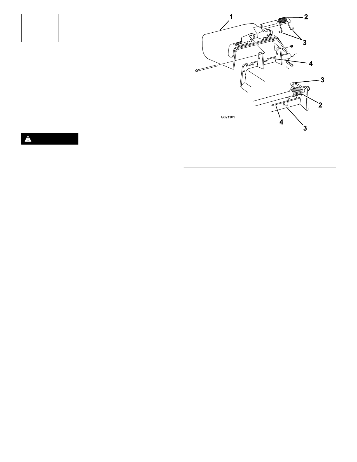
CheckingtheGrass
Deector
NoPartsRequired
Procedure
Ifthereareplastictiesholdingthegrassdeectorup,
removethemandlowerthedeectorintoplace.
WARNING
Anuncovereddischargeopeningcouldallow
themachinetothrowobjectstowardyouor
bystanders,resultinginseriousinjuryor
death.Also,contactwiththebladecould
occur.
Neveroperatethemachinewithoutacover
plate,amulchplate,grassdeector,orbagger
installed.
Figure4
1.Grassdeector3.Endofspring
2.Spring
4.Deckedge
g021181
1.Makesurethat1endofthespringisinstalled
behindthedeckedgebeforeinstallingthebolt
asshowninFigure4.
2.Placetheotherendofthespringaroundgrass
deector(Figure4).
Important:Thegrassdeectormustbefree
torotatewithdownwardtension.Liftthe
deectoruptothefullopenpositionand
ensurethatitrotatesfreely,withoutbinding
intothefulldownposition.
5
9
10
RemovingtheShipping
CableTies
NoPartsRequired
Procedure
Note:Thisprocedureisformachineswitha
MyRide™suspensionsystemonly.
CAUTION
Thespringsarecompressedbytheshipping
cableties.Whenyouremovethecableties,
theseatandspringswillraiseupquicklyby
approximately9cm(3-1/2inches),andcould
injureyou.
Ensurethatyourhands,arms,andfaceare
clearoftheseatandspringsbeforecutting
thecableties.
CheckingtheMachinefor
Grease
Partsneededforthisprocedure:
1tube
No.2lithiumormolybdenumgrease(purchase
separately)
Procedure
Beforeyouusethemachine,checkthemachinefor
grease;refertoLubricationintheOperator'sManual.
11
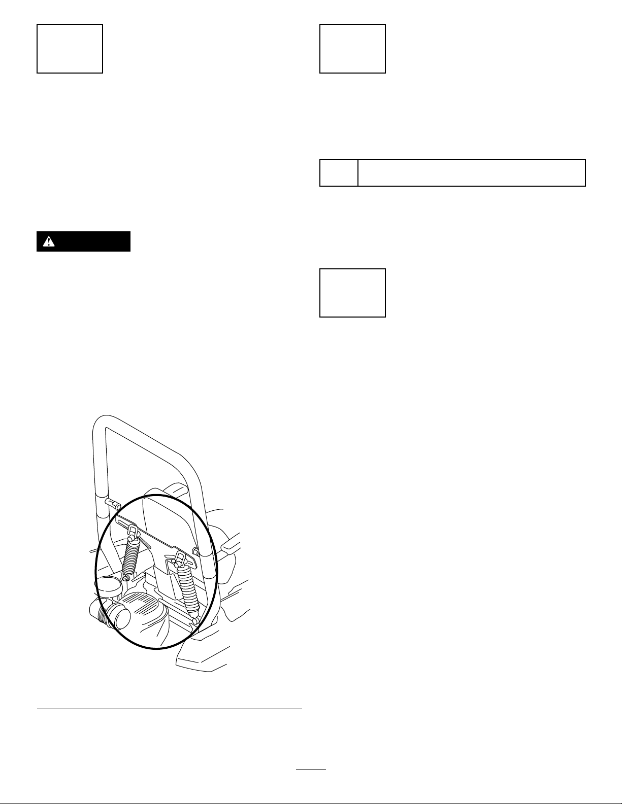
CheckingtheMower
Adjustment
Note:Removethecabletiesintheareashownin
Figure5beforeoperatingthemachine.
Figure5
NoPartsRequired
Procedure
Adjusttheside-to-sidelevelandthefront-to-rearblade
slope.UsetherelevantproceduresintheOperator's
Manualtoverifythatthedeckislevel,andmakeany
adjustmentsasneeded.
g228153
6

12
CheckingtheMachineBeforeDeliverytotheCustomer
(AllMachines)
NoPartsRequired
Procedure
Beforedeliveringthemachinetothecustomer,ensurethatyouhaveperformedtheprocedureslistedinthe
followingtableandinitialeachwhennished.RefertotheOperator'sManualforinstructionsonperforming
theseprocedures.
Initial
Checkthetirepressure.
Checkthelevelofthemowerdeck.
Checktheengine-oillevel.
Checkthehydraulic-uidlevel.
CheckthattheROPSissecure.
Checktheadjustmentoftheparkingbrake.
Ensurethatthemachinetrackscorrectly;refertotheOperator'sManualfortheadjustmentprocedure.
Checkthesafetyinterlocksystem;refertotheOperator'sManual.
EnsurethatthePTOworks.
Checkallfastenersthatyouinstalledtoensurethattheyaretight.
Whenyounishsettingupthemachine,signanddateinthespaceprovidedbelow:
Signature:
CheckProcedure
Date:
7

13
DeliveringtheMachinetotheCustomer
Partsneededforthisprocedure:
1
Operator'sManual
1
Engineowner'smanual(non-T oroengines)
1
Operatortrainingmaterial
2Key
1Registrationcard
Procedure
Atdelivery,llinthemodelandserialnumber,completetheitemslistedinthefollowingtable,andinitial
eachwhennished.
ModelNo.
SerialNo.
DealerInitial
CustomerInitialCheckProcedure
Showthecustomerwherethefollowingfeaturesarelocatedandhowtheyfunction:
•
Fueltank
•
Oil-llcap/Oildipstick
•
Sparkplug(s)
•
Engine-oillter
•
Engine-oildrain
•
Fuelgauge,valve,andhose
•
Airlter
•
Hydraulic-uidreservoir
•
Hydrauliclter
•
Battery
•
Ignitionswitch
•
Throttlelever
•
Choke(ifapplicable)
•
Power-takeoffswitch(PTO)
•
Motion-controllevers
•
Parkingbrake
•
Heightofcut
•
Lift-assistlever(ifapplicable)
•
Adjustableseat
•
Hydraulic-bypassvalves
•
RolloverProtectionSystem(ROPS)
8

DealerInitial
CustomerInitialCheckProcedure
RefertotheOperator'sManualtopointoutsafetyprocedures,operation,and
maintenanceprocedures.
ReviewthewarrantystatementasshownintheOperator'sManual.
Describethepost-saleserviceproceduresforyourstore.
Assistthecustomerinllingoutandmailingtheregistrationcardorregisteronline
atwww.Toro.com.
EnsurethatthecustomerreceivestheOperator'sManual,engineowner'smanual
(non-Toroengines),SetupInstructions,andoperatortrainingmaterial.
EnsurethatthecustomerknowsthatthePartsCatalogisavailableatwww .T oro.com.
Assistthecustomerinloadingthemachine.
Note:Whenyou,thedealerrepresentative,havenisheddeliveringthemachinetothecustomer,signand
dateinthespaceprovidebelowandkeepacopyofthispagefordealerrecords.Also,thedealermustremind
thecustomertouseafull-widthtrailerramptoloadthemachine.
Signature:
Signature:Date:
Date:
9

Notes:

Notes:

 Loading...