

Page 1

FormNo.3426-574RevB
48in,52in,or60inTITAN
1500,2000,or2500SeriesRiding
Mower
ModelNo.74452—SerialNo.404315000andUp
ModelNo.74453—SerialNo.400000000andUp
ModelNo.74454—SerialNo.400000000andUp
ModelNo.74463—SerialNo.404315000andUp
ModelNo.74465—SerialNo.404315000andUp
ModelNo.74466—SerialNo.404315000andUp
ModelNo.74467—SerialNo.404315000andUp
ModelNo.74470—SerialNo.404315000andUp
ModelNo.74471—SerialNo.404315000andUp
ModelNo.74472—SerialNo.404315000andUp
ModelNo.78450—SerialNo.404315000andUp
ModelNo.78472—SerialNo.404315000andUp
®
HD
Registeratwww.T oro.com.
OriginalInstructions(EN)
*3426-574*B
Page 2

ItisaviolationofCaliforniaPublicResourceCode
Section4442or4443touseoroperatetheengineon
anyforest-covered,brush-covered,orgrass-covered
landunlesstheengineisequippedwithaspark
arrester,asdenedinSection4442,maintainedin
effectiveworkingorderortheengineisconstructed,
equipped,andmaintainedforthepreventionofre.
GrossorNetTorque:Thegrossornettorque
ofthisenginewaslaboratoryratedbytheengine
manufacturerinaccordancewiththeSocietyof
AutomotiveEngineers(SAE)J1940orJ2723.As
conguredtomeetsafety,emission,andoperating
requirements,theactualenginetorqueonthisclass
ofmowerwillbesignicantlylower.Pleasereferto
theenginemanufacturer’sinformationincludedwith
themachine.
Important:IfyouareusingamachinewithaToro
engineabove1500m(5,000ft)foracontinuous
period,ensurethattheHighAltitudeKithasbeen
installedsothattheenginemeetsCARB/EP A
emissionregulations.TheHighAltitudeKit
increasesengineperformancewhilepreventing
spark-plugfouling,hardstarting,andincreased
emissions.Onceyouhaveinstalledthekit,attach
thehigh-altitudelabelnexttotheserialdecalon
themachine.ContactanyAuthorizedToroService
DealertoobtaintheproperHighAltitudeKitand
high-altitudelabelforyourmachine.Tolocate
adealerconvenienttoyou,accessourwebsite
atwww.T oro.comorcontactourToroCustomer
CareDepartmentatthenumber(s)listedinyour
EmissionControlWarrantyStatement.
Removethekitfromtheengineandrestorethe
enginetoitsoriginalfactorycongurationwhen
runningtheengineunder1500m(5,000ft).Do
notoperateanenginethathasbeenconverted
forhigh-altitudeuseatloweraltitudes;otherwise,
youcouldoverheatanddamagetheengine.
Ifyouareunsurewhetherornotyourmachine
hasbeenconvertedforhigh-altitudeuse,lookfor
thefollowinglabel.
WARNING
CALIFORNIA
Proposition65Warning
Theengineexhaustfromthisproduct
containschemicalsknowntotheStateof
Californiatocausecancer,birthdefects,
orotherreproductiveharm.
Batteryposts,terminals,andrelated
accessoriescontainleadandlead
compounds,chemicalsknownto
theStateofCaliforniatocause
cancerandreproductiveharm.Wash
handsafterhandling.
Useofthisproductmaycauseexposure
tochemicalsknowntotheStateof
Californiatocausecancer,birthdefects,
orotherreproductiveharm.
Introduction
Thisrotary-blade,ridinglawnmowerisintendedtobe
usedbyprofessional,hiredoperators.Itisdesigned
primarilyforcuttinggrassonwell-maintainedlawns
onresidentialorcommercialproperties.Usingthis
productforpurposesotherthanitsintendedusecould
provedangeroustoyouandbystanders.
Readthisinformationcarefullytolearnhowtooperate
andmaintainyourproductproperlyandtoavoid
injuryandproductdamage.Youareresponsiblefor
operatingtheproductproperlyandsafely .
Visitwww.Toro.comforproductsafetyandoperation
trainingmaterials,accessoryinformation,helpnding
adealer,ortoregisteryourproduct.
©2019—TheToro®Company
8111LyndaleAvenueSouth
Bloomington,MN55420
Figure4
Wheneveryouneedservice,genuineToroparts,or
additionalinformation,contactanAuthorizedService
DealerorToroCustomerServiceandhavethemodel
andserialnumbersofyourproductready.Figure1
orFigure2identiesthelocationofthemodeland
serialnumbersontheproduct.Writethenumbersin
decal127-9363
thespaceprovided.
Important:Withyourmobiledevice,youcan
scantheQRcodeontheserialnumberdecal(if
equipped)toaccesswarranty,parts,andother
productinformation.
Contactusatwww.Toro.com.
2
PrintedintheUSA
AllRightsReserved
Page 3
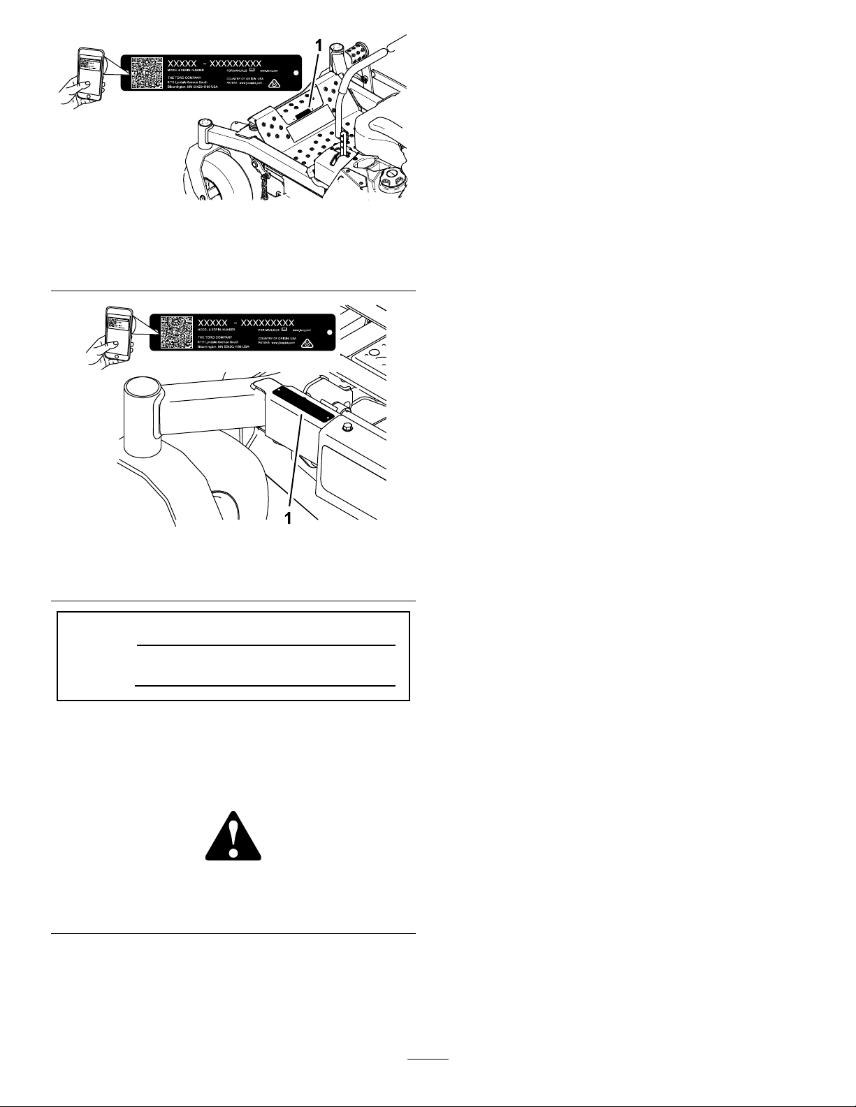
Figure1
MachineswithoutMyRide
1.Modelandserialnumberlocation
Figure2
MachineswithMyRide
ModelNo.
SerialNo.
Thismanualidentiespotentialhazardsandhas
safetymessagesidentiedbythesafety-alertsymbol
(Figure3),whichsignalsahazardthatmaycause
seriousinjuryordeathifyoudonotfollowthe
recommendedprecautions.
Figure3
Safety-alertsymbol
Thismanualuses2wordstohighlightinformation.
Importantcallsattentiontospecialmechanical
informationandNoteemphasizesgeneralinformation
worthyofspecialattention.
Contents
Safety.......................................................................5
SafetyAlertSymbol............................................5
GeneralSafety...................................................5
SlopeIndicator...................................................6
SafetyandInstructionalDecals..........................7
ProductOverview...................................................16
Controls...........................................................16
g233854
g233855
g000502
Specications..................................................18
Attachments/Accessories.................................18
BeforeOperation.................................................19
BeforeOperationSafety...................................19
AddingFuel......................................................20
PerformingDailyMaintenance..........................21
BreakinginaNewMachine..............................21
UsingtheRollover-ProtectionSystem
(ROPS).........................................................21
UsingtheSafety-InterlockSystem....................22
PositioningtheSeat..........................................23
ChangingtheSeatSuspension.........................23
AdjustingtheRear-ShockAssemblies..............24
UsingAttachmentsandAccessories.................25
DuringOperation.................................................25
DuringOperationSafety...................................25
EnteringtheOperator’sPosition.......................27
OperatingtheParkingBrake.............................28
OperatingtheMowerBlade-ControlSwitch
(PTO)............................................................28
OperatingtheThrottle.......................................29
OperatingtheChoke........................................29
StartingtheEngine...........................................30
ShuttingOfftheEngine.....................................30
UsingtheMotion-ControlLevers.......................32
DrivingtheMachine..........................................32
UsingtheSideDischarge.................................33
AdjustingtheHeightofCut...............................33
AdjustingtheAnti-ScalpRollers........................34
AdjustingtheSideBumpers..............................35
OperatingTips.................................................36
AfterOperation....................................................36
AfterOperationSafety......................................36
UsingtheFuel-ShutoffValve.............................37
UsingtheDrive-WheelReleaseValves.............37
TransportingtheMachine.................................38
Maintenance...........................................................40
MaintenanceSafety..........................................40
RecommendedMaintenanceSchedule(s)...........41
Lubrication..........................................................43
GreasingtheMachine.......................................43
GreasingtheCaster-WheelHubs.....................43
EngineMaintenance...........................................44
EngineSafety...................................................44
IdentifyingtheEngine.......................................44
ServicingaKawasaki
ServicingaKohler
®
Engine..........................45
®
Engine...............................50
ServicingaT oroEngine....................................54
CleaningtheBlowerHousing............................59
3
Page 4

CleaningtheCoolingSystem............................59
CheckingtheSparkArrester.............................60
ReplacingtheEmissions-AirIntake
Filter..............................................................60
FuelSystemMaintenance...................................60
ReplacingtheFuelFilter...................................60
ServicingtheFuelT ank.....................................61
ElectricalSystemMaintenance...........................61
ElectricalSystemSafety...................................61
ServicingtheBattery.........................................61
ServicingtheFuses..........................................63
DriveSystemMaintenance..................................64
CheckingtheSeatBelt.....................................64
CheckingtheRoll-BarKnobs............................64
AdjustingtheTracking......................................65
CheckingtheTirePressure...............................65
CheckingtheWheelLugNuts...........................65
CoolingSystemMaintenance..............................66
CleaningtheEngineScreen.............................66
BrakeMaintenance.............................................66
AdjustingtheParkingBrake..............................66
BeltMaintenance................................................68
InspectingtheBelts..........................................68
ReplacingtheMowerBeltforSide-Discharge
MowerDecks................................................68
ReplacingtheMowerBeltforRear-Discharge
MowerDecks................................................69
ReplacingtheHydraulicPump-Drive
Belt................................................................71
ControlsSystemMaintenance.............................72
AdjustingtheControl-HandlePosition..............72
AdjustingtheMotion-ControlLinkage...............73
HydraulicSystemMaintenance...........................74
HydraulicSystemSafety...................................74
HydraulicFluidSpecications...........................74
CheckingtheHydraulicFluidLevel...................74
ChangingtheHydraulicFluidand
Filters............................................................74
BleedingtheHydraulicSystem.........................76
MowerDeckMaintenance....................................77
ServicingtheCuttingBlades.............................77
AdjustingtheSide-to-SideLevelingandthe
BladeSlope..................................................80
RemovingtheMowerDeck...............................82
ReplacingtheGrassDeector..........................83
Cleaning..............................................................84
CleaningundertheMowerDeck.......................84
CleaningtheSuspensionSystem.....................84
DisposingofWaste...........................................84
Storage...................................................................85
StorageSafety..................................................85
CleaningandStorage.......................................85
Troubleshooting......................................................86
Schematics.............................................................88
4
Page 5

Safety
Thismachinehasbeendesignedinaccordancewith
ANSIstandardB71.4-2017.
SafetyAlertSymbol
ThisSafetyAlertSymbol(Figure5)isusedbothin
thismanualandonthemachinetoidentifyimportant
safetymessageswhichmustbefollowedtoavoid
accidents.
Thissymbolmeans:ATTENTION!BECOMEALERT!
YOURSAFETYISINVOL VED!
Figure5
SafetyAlertSymbol
Thesafetyalertsymbolappearsaboveinformation
whichalertsyoutounsafeactionsorsituationsand
willbefollowedbythewordDANGER,WARNING,or
CAUTION.
•Onlyallowtrained,responsible,andphysically
capableoperatorsthatarefamiliarwiththesafe
operation,operatorcontrols,andsafetysignsand
instructionstooperatethemachine.Neverlet
childrenoruntrainedpeopleoperateorservicethe
equipment.Localregulationsmayrestricttheage
oftheoperator.
•Alwayskeeptherollbarinthefullyraisedand
lockedpositionandusetheseatbelt.
•Donotoperatethemachineneardrop-offs,
ditches,embankments,water,orotherhazards,or
onslopesgreaterthan15degrees.
•Donotputyourhandsorfeetnearmoving
componentsofthemachine.
•Neveroperatethemachinewithdamagedguards,
g000502
shields,orcovers.Alwayshavesafetyshields,
guards,switchesandotherdevicesinplaceandin
properworkingcondition.
•Stopthemachine,shutofftheengine,andremove
thekeybeforeservicing,fueling,orunclogging
themachine.
DANGER:Indicatesanimminentlyhazardous
situationwhich,ifnotavoided,Willresultindeathor
seriousinjury.
WARNING:Indicatesapotentiallyhazardoussituation
which,ifnotavoided,Couldresultindeathorserious
injury.
CAUTION:Indicatesapotentiallyhazardoussituation
which,ifnotavoided,Mayresultinminorormoderate
injury.
Thismanualusestwootherwordstohighlight
information.Importantcallsattentiontospecial
mechanicalinformationandNoteemphasizesgeneral
informationworthyofspecialattention.
GeneralSafety
Thismachineiscapableofamputatinghandsandfeet
andofthrowingobjects.T orodesignedandtested
thislawnmowertoofferreasonablysafeservice;
however,failuretocomplywithsafetyinstructions
mayresultininjuryordeath.
•Read,understand,andfollowallinstructionsand
warningsintheOperator’sManualandother
trainingmaterial,onthemachine,engine,and
attachments.Alloperatorsandmechanicsshould
betrained.Iftheoperator(s)ormechanic(s)can
notreadthismanual,itistheowner’sresponsibility
toexplainthismaterialtothem;otherlanguages
maybeavailableonourwebsite.
5
Page 6

SlopeIndicator
Figure6
Youmaycopythispageforpersonaluse.
1.Themaximumslopeyoucanoperatethemachineonis15degrees.Usetheslopecharttodeterminethedegreeofslopeof
hillsbeforeoperating.Donotoperatethismachineonaslopegreaterthan15degrees.Foldalongtheappropriateline
tomatchtherecommendedslope.
2.Alignthisedgewithaverticalsurface,atree,building,fencepole,etc.
3.Exampleofhowtocompareslopewithfoldededge
6
g011841
Page 7
SafetyandInstructionalDecals
Safetydecalsandinstructionsareeasilyvisibletotheoperatorandarelocatednearanyarea
ofpotentialdanger.Replaceanydecalthatisdamagedormissing.
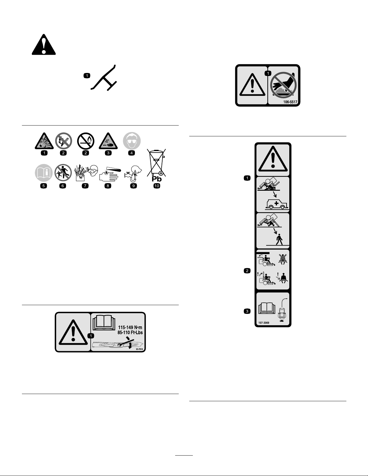
Manufacturer'sMark
1.Indicatesthebladeisidentiedasapartfromtheoriginal
machinemanufacturer.
BatterySymbols
Someorallofthesesymbolsareonyourbattery .
decaloemmarkt
decal106-5517
106-5517
1.Warning—donottouchthehotsurface.
decalbatterysymbols
1.Explosionhazard6.Keepbystandersaway
2.Nore,opename,or
smoking
3.Causticliquid/chemical
burnhazard
4.Weareyeprotection.9.Flusheyesimmediately
5.ReadtheOperator's
Manual.
fromthebattery .
7.Weareyeprotection;
explosivegasescan
causeblindnessandother
injuries.
8.Batteryacidcancause
blindnessorsevereburns.
withwaterandgetmedical
helpfast.
10.Containslead;donot
discard
93-7818
1.Warning—readtheOperator'sManualforinstructionson
torquingthebladebolt/nutto1 15to149N∙m(85to110
ft-lb).
decal107-3069
107-3069
1.Warning—thereisnorolloverprotectionwhentherollbaris
decal93-7818
down.
2.Toavoidinjuryordeathfromarolloveraccident,keepthe
rollbarinthefullyraisedandlockedpositionandwear
theseatbelt.Lowertherollbaronlywhenabsolutely
necessary;donotweartheseatbeltwhentherollbaris
down.
3.ReadtheOperator'sManual;driveslowlyandcarefully.
7
Page 8
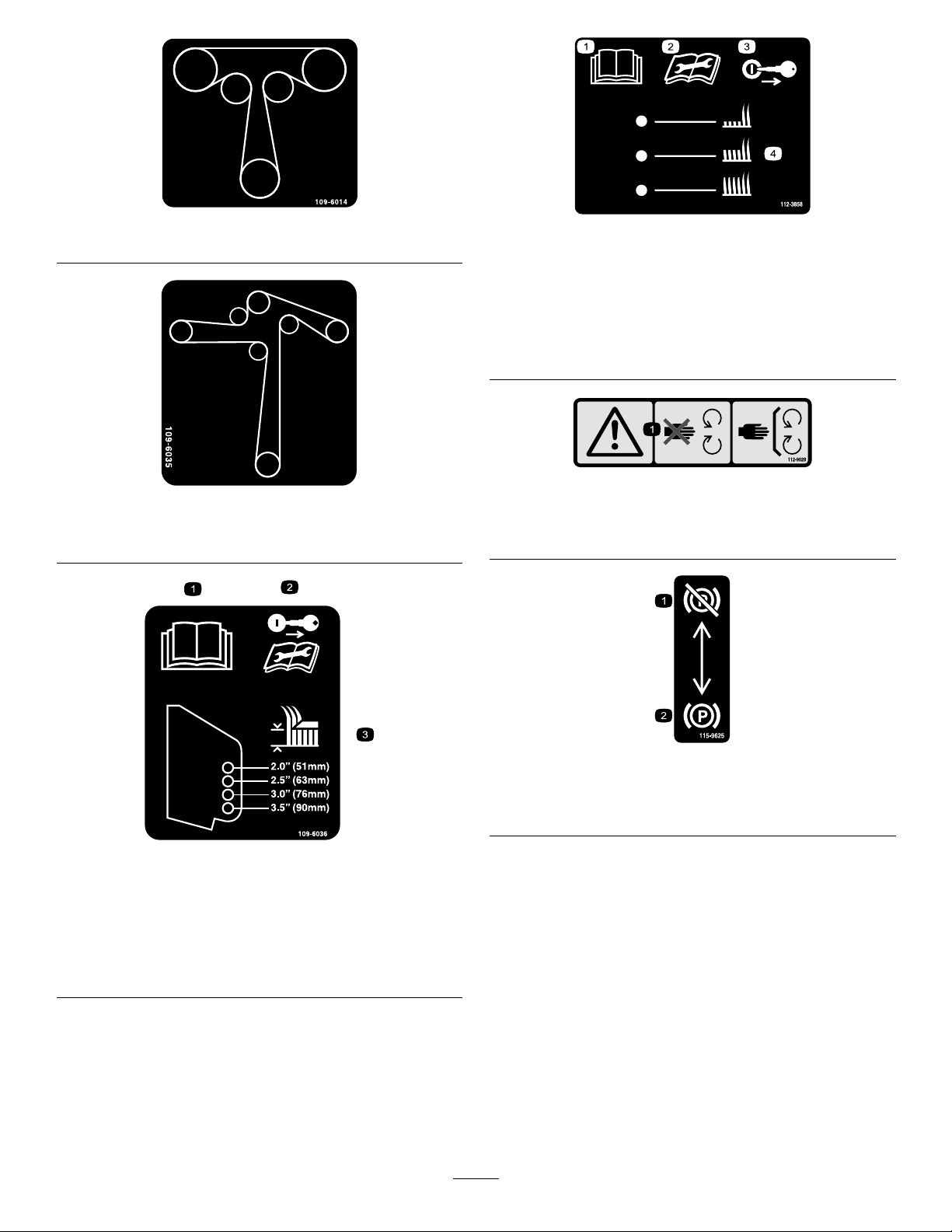
decal109-6014
109-6014
112-3858
decal112-3858
1500and2000SeriesSideDischargeMachinesOnly
109-6035
2500SeriesSideDischargeMachinesOnly
1.ReadtheOperator's
Manual.
2.Readtheinstructions
3.Removethekeybefore
adjustingtheheightofcut.
4.Height-of-cutsettings.
beforeservicingor
performingmaintenance.
decal112-9028
decal109-6035
112-9028
1.Warning—stayawayfrommovingparts;keepallguards
andshieldsinplace.
109-6036
RearDischargeMachinesOnly
1.ReadtheOperator’sManual.
2.Removethekeyandreadtheinstructionsbeforeservicing
orperformingmaintenance.
3.Heightofcut
decal115-9625
115-9625
1.Parking
brake—disengaged
decal109-6036
2.Parkingbrake—engaged
8
Page 9
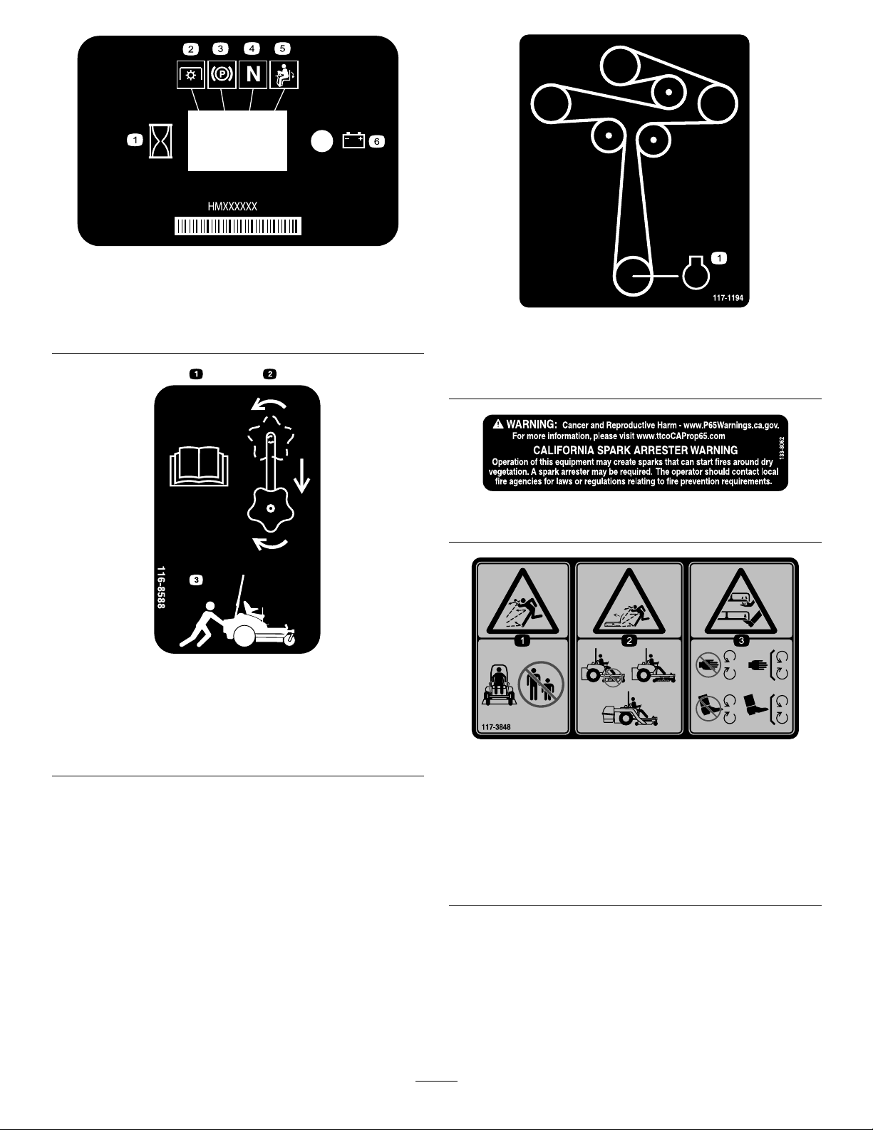
116-5610
1.Hourmeter4.Neutral
2.Powertakeoff(PTO)5.Operator-presenceswitch
3.Parkingbrake6.Battery
116-8588
decal116-5610
decal117-1 194
117-1194
1500and2000SeriesSide-DischargeMachinesOnly
1.Engine
decal133-8062
133-8062
decal116-8588
1.ReadtheOperator’sManual.
2.Rotatethedrivereleaseknobtoloosen,slidetheknob,
andtighten.
3.Pushthemachine.
decal117-3848
117-3848
1.Thrownobjecthazard—keepbystandersaway.
2.Thrownobjecthazard,raiseddeector—donotoperate
withoutthedeector ,dischargecover ,orgrasscollection
systeminplace.
3.Cutting/dismembermenthazardofhandorfoot,mower
blade—stayawayfrommovingparts;keepallguardsand
shieldsinplace.
9
Page 10

126-0768
126-4363
1.Cutting/dismembermenthazard,fanandentanglement
hazard,belt.Shutofftheengineandremovethekeybefore
adjusting,servicingorcleaningthemachine.
decal126-0768
decal126-4784
126-4784
1.Heightofcut
decal126-4363
decal126-6599
126-6599
RearDischargeMachinesOnly
1.Thrownobjects
hazard—keepbystanders
away.
2.Cutting/dismemberment
ofhand—stayawayfrom
movingparts;keepall
guardsandshieldsin
place.
10
Page 11
decal126-8161
126-8161
1.ReadtheOperator’s
Manual.
2.Slideseatforward
1.ReadtheOperator’s
Manual.
3.Pressdownonlatchto
unlockseat
4.Rotateseat
126-9939
2.Filltothebottomofthe
llerneck;warning—do
notoverllthetank.
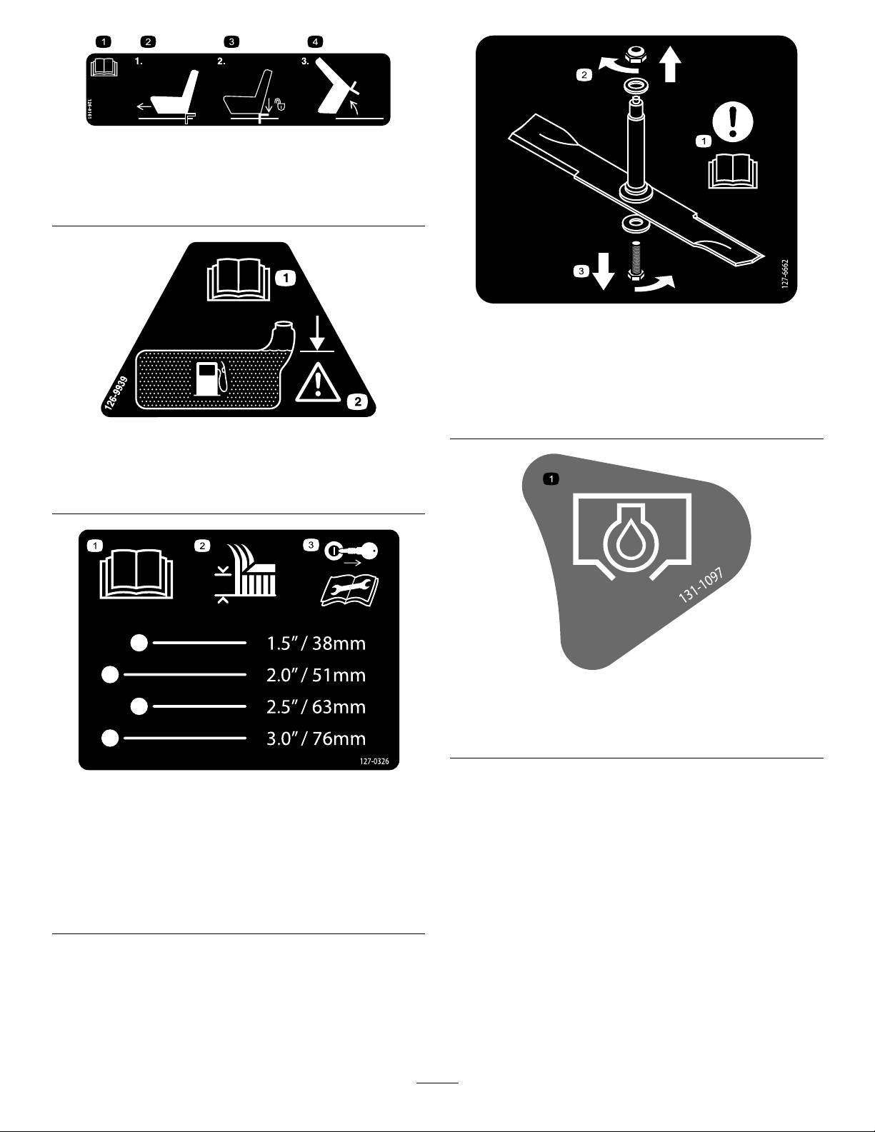
decal127-6662
127-6662
RearDischargeMowersOnly
1.Attention—readthe
Operator'sManual.
2.Removethenutbyturning
decal126-9939
itclockwise.
3.Removetheboltbyturning
itcounterclockwise.
127-0326
2500SeriesSideDischargeMachinesOnly
1.ReadtheOperator's
Manual.
2.Heightofcut
decal131-1097
131-1097
ToroEnginesOnly
1.Oildrain
decal127-0326
3.Removethekeyand
readtheOperator's
Manualbeforeperforming
maintenanceorservicing
themachine.
11
Page 12
PTOSwitchSymbols
1.PTO–disengage2.PTO–engage
decalptosymbols
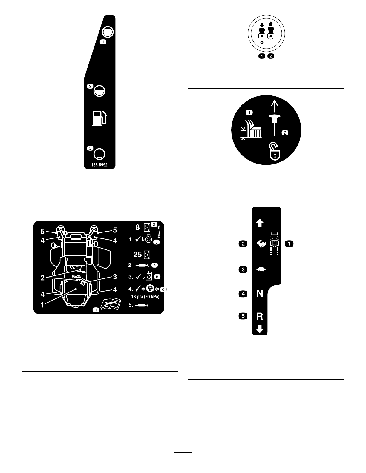
136-8992
MachineswithMyRideOnly
1.Fuel—full
2.Fuel—50%
3.Fuel—empty
136-9024
1.ReadtheOperator’s
Manualbeforeperforming
maintenance.
2.Operatinghours5.Hydraulic-uidlevel
3.Engine-oillevel6.Tirepressure
4.Greasepoint
decal136-8992
1.Heightofcut
TransportLock
2.Pulluptounlockthe
decaltransportlock
transportlock.
decal136-9024
decalmotioncntrllh-126-6194
LeftMotionControl
1.Machinespeed4.Neutral
2.Fast5.Reverse
3.Slow
12
Page 13
RightMotionControl
1.Machinespeed4.Neutral
2.Fast5.Reverse
3.Slow
decalmotioncntrlrh-126-6183
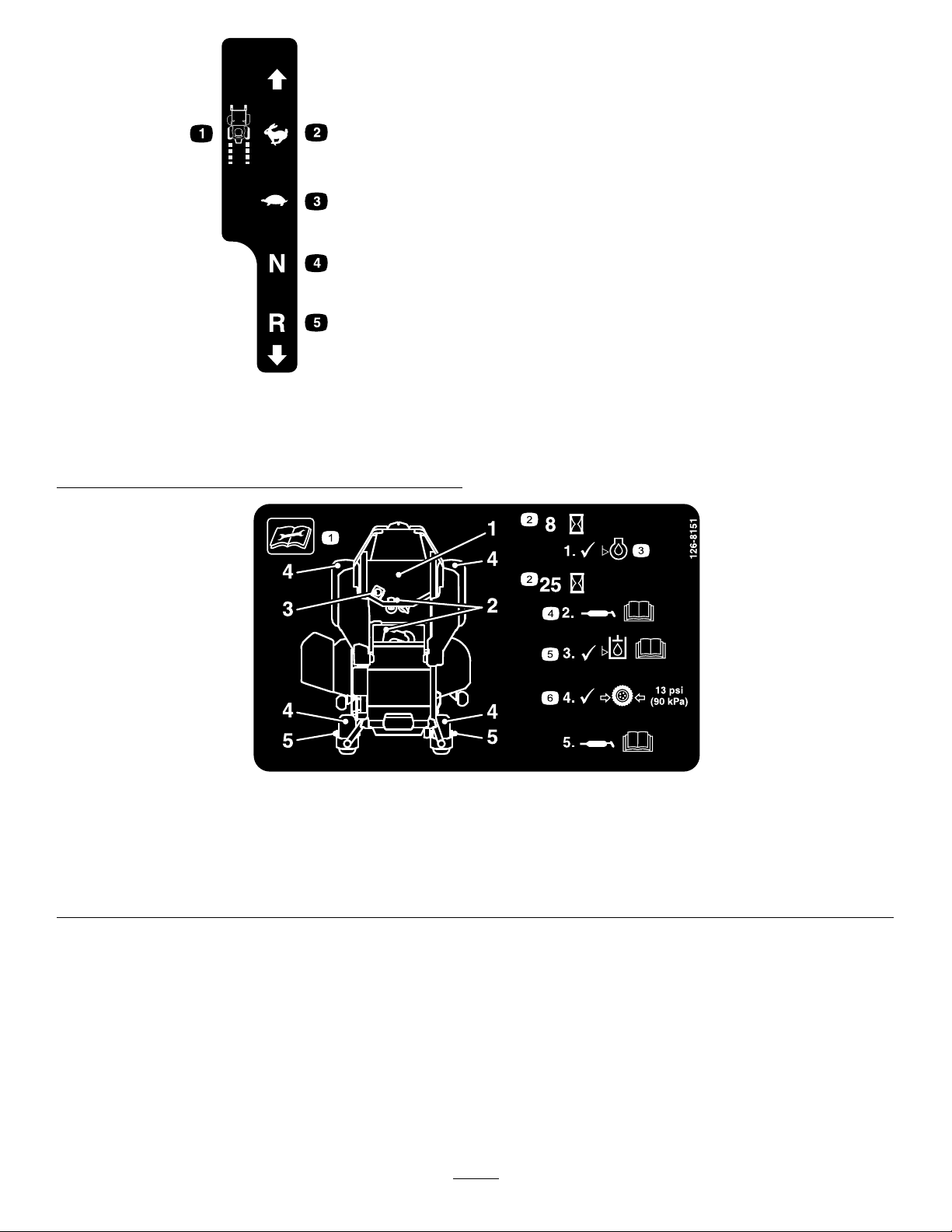
decal126-8151
126-8151
1.Readtheinstructionsbeforeservicingorperforming
4.RefertotheOperator'sManualforgreaseinstructions.
maintenanceonthemachine.
2.Timeinterval
5.Checkthehydraulic-uidlevelandrefertotheOperator's
Manualforfurtherinstructions.
3.Checktheoillevel.6.Checkthetirepressure.
13
Page 14
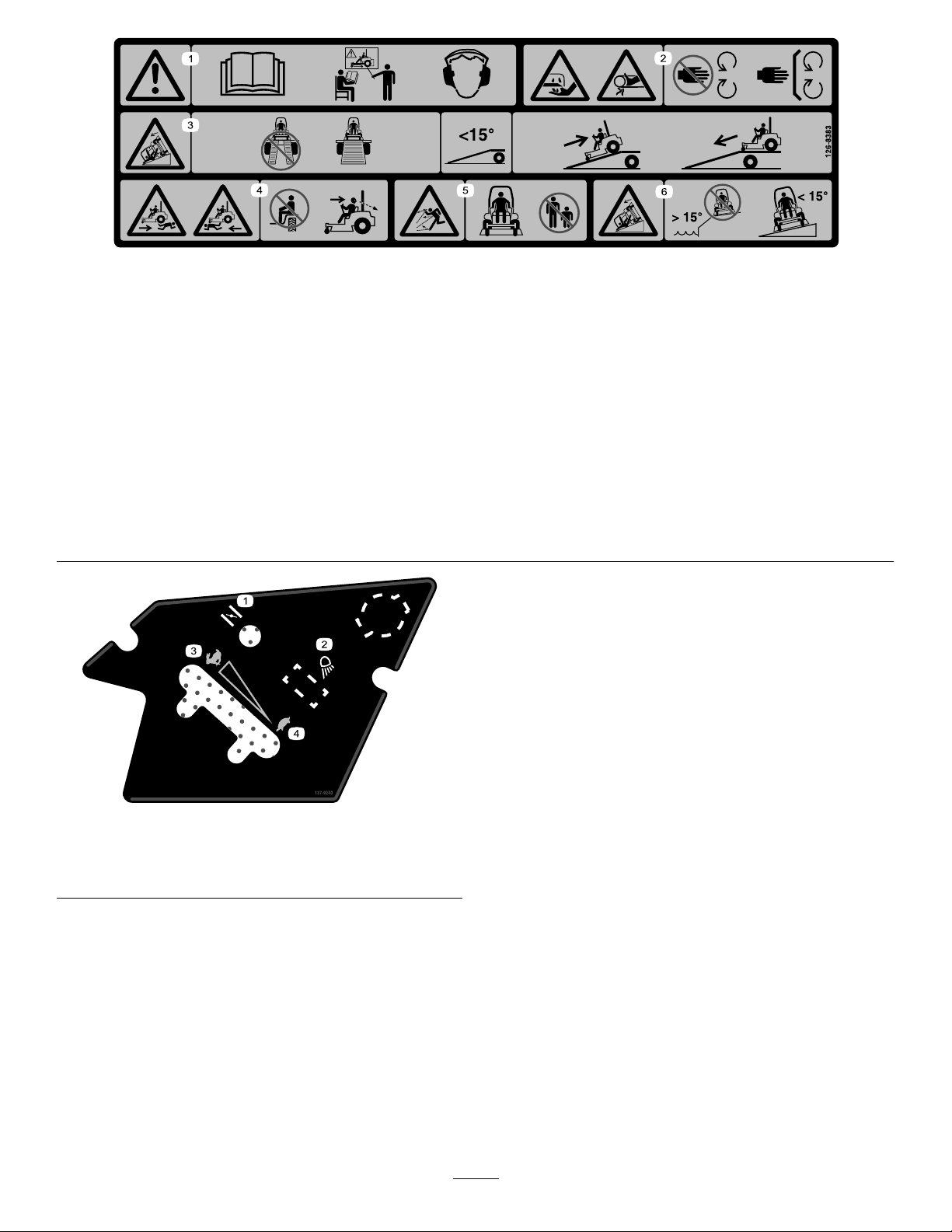
126-8383
Note:Thismachinecomplieswiththeindustrystandardstabilitytestinthestaticlateralandlongitudinaltestswiththemaximum
recommendedslopeindicatedonthedecal.ReviewtheinstructionsforoperatingthemachineonslopesintheOperator’sManualas
wellastheconditionsinwhichyouwouldoperatethemachinetodeterminewhetheryoucanoperatethemachineintheconditions
onthatdayandatthatsite.Changesintheterraincanresultinachangeinslopeoperationforthemachine.Ifpossible,keepthe
cuttingunitsloweredtothegroundwhileoperatingthemachineonslopes.Raisingthecuttingunitswhileoperatingonslopescan
causethemachinetobecomeunstable.
decal126-8383
1.Warning—readtheOperator’sManual;donotoperatethis
machineunlessyouaretrained;wearhearingprotection.
2.Cutting/dismembermenthazardofthehand,mowerblade;
entanglementhazardofthehand,belt—stayawayfrom
movingparts;keepallguardsandshieldsinplace.
3.Ramphazard—donotusedualrampswhenloadingontoa
trailer;use1rampwideenoughforthemachine;usearamp
withaslopelessthan15°;backuptherampwhenloadingthe
machineanddriveforwardofftherampwhenunloading.
decal137-9240
137-9240
4.Runover/backoverhazard—donotcarrypassengers;look
behindyouwhenmowinginreverse.
5.Thrownobjecthazard—keepbystandersaway.
6.Tippinghazard—donotuseonslopesnearopenwater;do
notuseonslopesgreaterthan15°.
1.Choke
2.Worklight
3.Fast
4.Slow
14
Page 15
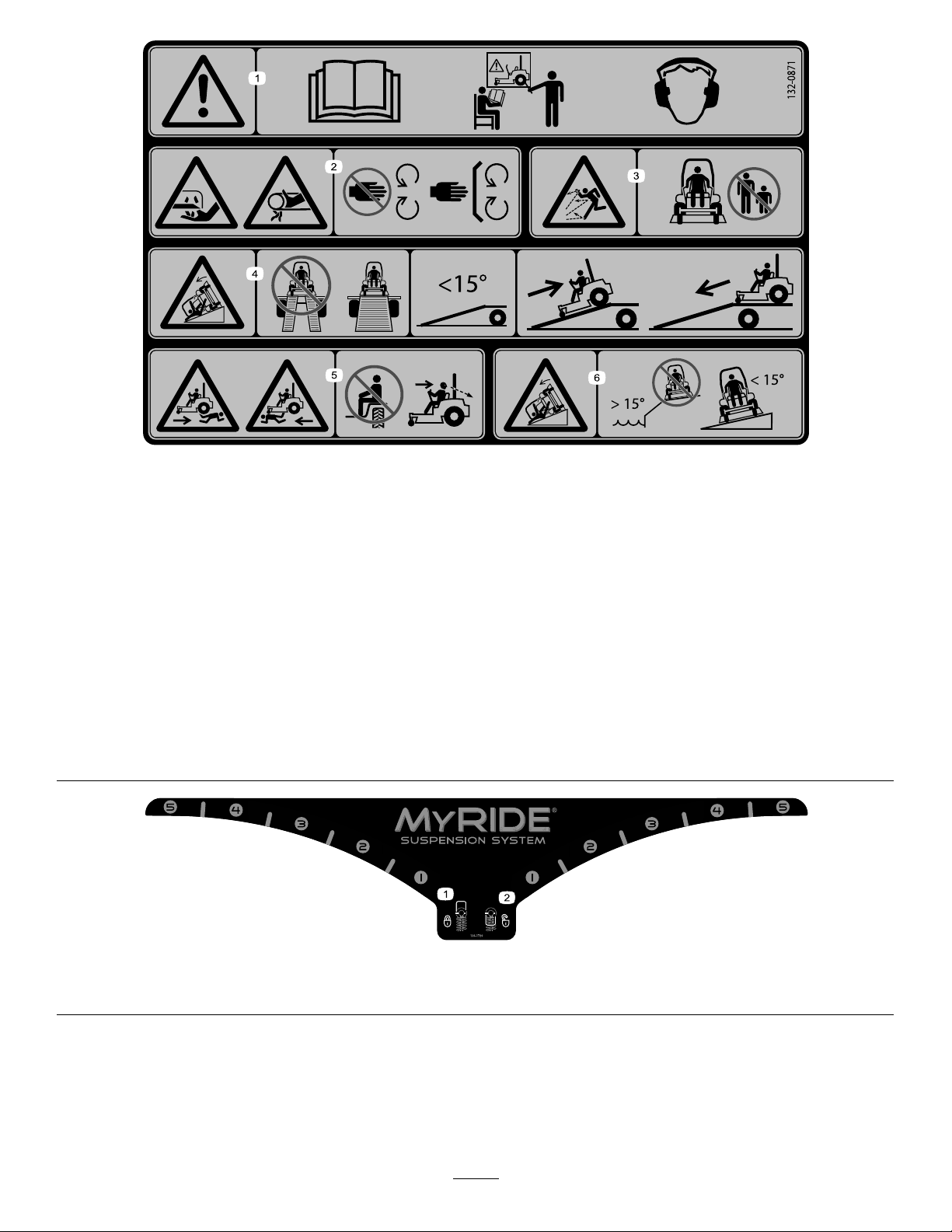
132-0871
MachineswithMyRideOnly
Note:Thismachinecomplieswiththeindustrystandardstabilitytestinthestaticlateralandlongitudinaltestswiththemaximum
recommendedslopeindicatedonthedecal.ReviewtheinstructionsforoperatingthemachineonslopesintheOperator’sManualas
wellastheconditionsinwhichyouwouldoperatethemachinetodeterminewhetheryoucanoperatethemachineinthoseconditions
onthatdayandatthatsite.Changesintheterraincanresultinachangeinslopeoperationforthemachine.Ifpossible,keepthe
cuttingunitsloweredtothegroundwhileoperatingthemachineonslopes.Raisingthecuttingunitswhileoperatingonslopescan
causethemachinetobecomeunstable.
decal132-0871
1.Warning—readtheOperator’sManual;donotoperatethis
machineunlessyouaretrained;wearhearingprotection.
4.Ramphazard—whenloadingontoatrailer,donotusedual
ramps;onlyuseasingularrampwideenoughforthemachine
andthathasaninclinelessthan15°;backuptheramp(in
reverse)anddriveforwardofftheramp.
2.Cutting,dismembering,andentanglementhazard—keep
handsawayfrommovingparts;keepallguardsandshieldsin
5.Bodilyharmhazard—donotcarrypassengers;lookbehind
youwhenmowinginreverse.
place.
3.Thrownobjecthazard—keepbystandersaway.6.Tippinghazardonslopes—donotuseonslopesnearopen
water;donotuseonslopesgreaterthan15°.
136-1720
1.Camlock2.Camunlock
decal136-1720
15
Page 16
ProductOverview
KeySwitch
Thekeyswitch,usedtostartandshutofftheengine,
has3positions:OFF,RUN,andST ART.Referto
StartingtheEngine(page30).
ChokeControl
Usethechokecontroltostartacoldengine.
ThrottleControl
Thethrottlecontrolstheenginespeed,andithasa
continuous-variablesettingfromtheSLOWtoFAST
position(Figure8).
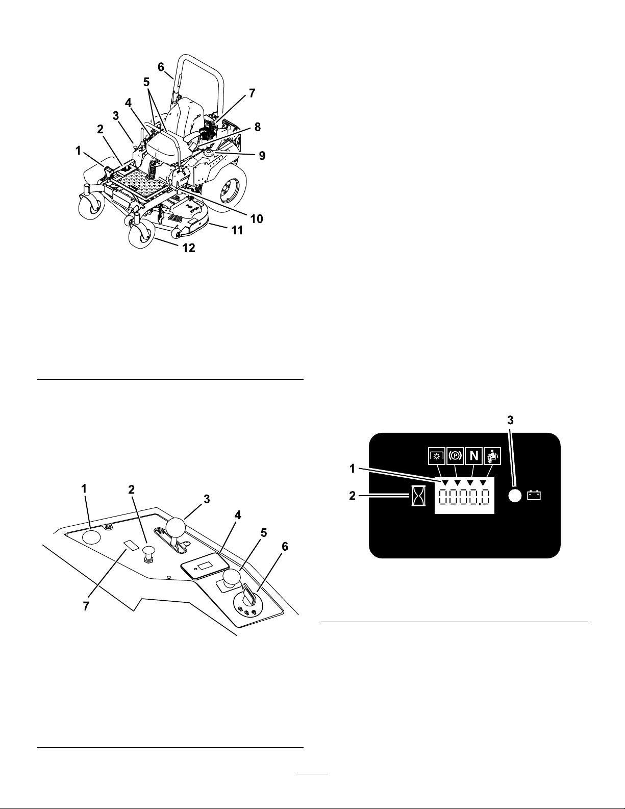
Figure7
1.Height-of-cutdeck-lift
pedal
2.Height-of-cutpositions8.Seatbelt
3.Transportlock9.Fuelcap
4.Controls
5.Motion-controllevers11.Mowerdeck
6.Rollbar
7.Shockassembly
10.Parking-brakelever
12.Casterwheel
Controls
Becomefamiliarwithallthecontrolsbeforeyoustart
theengineandoperatethemachine.
ControlPanel
g227688
Blade-ControlSwitch(Power
Takeoff)
Theblade-controlswitch,representedbya
power-takeoff(PTO)symbol,engagesand
disengagespowertothemowerblades(Figure8).
HourMeter
Thehourmeterrecordsthenumberofhoursthe
enginehasoperated.Itoperateswhentheengine
isrunning.Usethesetimesforschedulingregular
maintenance(Figure9).
1.Positionforoptionalpower
point
2.Chokecontrol
3.Throttlecontrol
4.Hourmeter
Figure8
5.Blade-controlswitch
(powertakeoff)
6.Keyswitch
7.Switchpositionforoptional
lightkit
g187133
Figure9
1.Safety-interlocksymbols
2.Hourmeter
g271171
3.Batterylight
Safety-InterlockIndicators
Therearesymbolsonthehourmeterthatindicate
withablacktrianglethattheinterlockcomponentis
positionedcorrectly(Figure9).
16
Page 17

Battery-IndicatorLight
IfyouturnthekeyswitchtotheONpositionfora
fewseconds,thebatteryvoltagedisplaysinthearea
wherethehoursarenormallydisplayed.
Thebatterylightturnsonwhenthekeyswitchis
turnedonandwhenthechargeisbelowthecorrect
operatinglevel(Figure9).
Motion-ControlLevers
Usethemotion-controlleverstodrivethemachine
forward,reverse,andturneitherdirection(Figure7).
Neutral-LockPosition
Movethemotion-controlleversoutwardfromthe
centertotheNEUTRAL-LOCKpositionwhenexiting
themachine(Figure30).Alwayspositionthe
motion-controlleversintotheNEUTRAL-LOCKposition
whenyoustopthemachineorleaveitunattended.
Parking-BrakeLever
Wheneveryoushutofftheengine,engagetheparking
braketopreventaccidentalmovementofthemachine.
Fuel-ShutoffValve
Closethefuel-shutoffvalvewhentransportingor
storingthemachine;refertoUsingtheFuel-Shutoff
Valve(page37).
17
Page 18

Specications
Note:Specicationsanddesignaresubjecttochangewithoutnotice.
Width—MachineswithSideDischargeMowerDecks
48-inchDeck52-inchDeck60-inchDeck
Withoutmowerdeck
Deectorup133cm(53inches)144cm(56-3/4inches)161cm(63-1/2inches)
Deectordown160cm(63-1/4inches)171cm(67-1/4inches)191cm(75-1/4inches)
Width—MachineswithRearDischargeMowerDecks
Withoutmowerdeck
Withmowerdeck
Length—MachineswithSideDischargeMowerDecks
Length
Length—MachineswithRearDischargeMowerDecks
121cm(47-1/2inches)124cm(49inches)133cm(52inches)
60-inchDeck
133cm(52inches)
168cm(66inches)
48-inchDeck52-inchDeck60-inchDeck
208cm(82inches)208cm(82inches)209cm(83inches)
60-inchDeck
Withmowerdeck
215cm(84-1/2inches)
Height
RollBar-UpRollBar-Down
179cm(70-1/2inches)125cm(49inches)
Weight
MachinesWeight
48-inchside-dischargemachines
52-inchside-dischargemachines
60-inchside-dischargemachines
60-inchrear-dischargemachines
385to425kg(849to937lb)
391to434kg(862to957lb)
409to456kg(901to1,006lb)
459kg(1,012lb)
Attachments/Accessories
AselectionofToroapprovedattachmentsandaccessoriesisavailableforusewiththemachinetoenhance
andexpanditscapabilities.ContactyourAuthorizedServiceDealerorauthorizedT orodistributororgoto
www.T oro.comforalistofallapprovedattachmentsandaccessories.
Toensureoptimumperformanceandcontinuedsafetycerticationofthemachine,useonlygenuineT oro
replacementpartsandaccessories.Replacementpartsandaccessoriesmadebyothermanufacturerscouldbe
dangerous,andsuchusecouldvoidtheproductwarranty .
18
Page 19

Operation
Note:Determinetheleftandrightsidesofthe
machinefromthenormaloperatingposition.
BeforeOperation
BeforeOperationSafety
GeneralSafety
•Evaluatetheterraintodeterminewhataccessories
andattachmentsareneededtoproperlyand
safelyperformthejob.Onlyuseaccessoriesand
attachmentsapprovedbyToro.
FuelSafety
Useextremecarewhenhandlingfuel.
DANGER
Incertainconditionsgasolineisextremely
ammableandvaporsareexplosive.
Areorexplosionfromgasolinecanburn
you,others,andcausepropertydamage.
•Fillthefueltankoutdoorsonlevelground,
inanopenarea,whentheengineiscold.
Wipeupanygasolinethatspills.
•Neverrellthefueltankordrainthe
machineindoorsorinsideanenclosed
trailer.
•Inspecttheareawheretheequipmentistobe
usedandremoveallrocks,toys,sticks,wires,
bones,andotherforeignobjects.Thesecan
bethrownorinterferewiththeoperationofthe
machineandmaycausepersonalinjurytothe
operatororbystanders.
•Wearappropriatepersonalprotectiveequipment
suchassafetyglasses,substantialslip-resistant
footwear,andhearingprotection.Tiebacklong
hairandavoidlooseclothingandloosejewelry
whichmaygettangledinmovingparts.
CAUTION
Thismachineproducessoundlevelsin
excessof85dBAattheoperator’searand
cancausehearinglossthroughextended
periodsofexposure.
Wearhearingprotectionwhenoperating
thismachine.
•Checkthattheoperatorpresencecontrols,
safetyswitches,andshieldsareattachedand
functioningproperly.Donotoperateunlessthey
arefunctioningproperly.
•DoNotllthefueltankcompletelyfull.
Fillthefueltanktothebottomoftheller
neck.Theemptyspaceinthetankallows
gasolinetoexpand.Overllingmayresult
infuelleakageordamagetotheengineor
emissionsystem.
•Neversmokewhenhandlinggasoline,and
stayawayfromanopenameorwhere
gasolinefumesmaybeignitedbyspark.
•Storegasolineinanapprovedcontainer
andkeepitoutofthereachofchildren.
•Addfuelbeforestartingtheengine.Never
removethecapofthefueltankoraddfuel
whenengineisrunningorwhentheengine
ishot.
•Iffuelisspilled,DoNotattempttostart
theengine.Moveawayfromtheareaof
thespillandavoidcreatinganysourceof
ignitionuntilfuelvaporshavedissipated.
•DoNotoperatewithoutentireexhaust
systeminplaceandinproperworking
condition.
•Donotoperatethemowerwhenpeople,especially
children,orpetsareinthearea.Stopthemachine
andattachment(s)ifanyoneentersthearea.
•Donotoperatethemachinewithouttheentire
grasscollectionsystem,dischargedeector,
orothersafetydevicesinplaceandinproper
workingcondition.Grasscatchercomponents
aresubjecttowear,damageanddeterioration,
whichcouldexposemovingpartsorallowobjects
tobethrown.Frequentlycheckforwornor
deterioratingcomponentsandreplacethemwith
themanufacturer’srecommendedpartswhen
necessary.
19
Page 20

DANGER
Incertainconditionsduringfueling,static
electricitycanbereleasedcausingaspark
whichcanignitegasolinevapors.Areor
explosionfromgasolinecanburnyouand
othersandcausepropertydamage.
•Alwaysplacegasolinecontainersonthe
groundawayfromyourvehiclebefore
lling.
•DoNotllgasolinecontainersinsidea
vehicleoronatruckortrailerbedbecause
interiorcarpetsorplastictruckbedliners
mayinsulatethecontainerandslowthe
lossofanystaticcharge.
•Whenpractical,removegas-powered
equipmentfromthetruckortrailerand
refueltheequipmentwithitswheelsonthe
ground.
•Ifthisisnotpossible,thenrefuelsuch
equipmentonatruckortrailerfroma
portablecontainer,ratherthanfroma
gasolinedispensernozzle.
•Ifagasolinedispensernozzlemustbe
used,keepthenozzleincontactwiththe
rimofthefueltankorcontaineropeningat
alltimesuntilfuelingiscomplete.DoNot
useanozzlelockopendevice.
WARNING
Gasolineisharmfulorfatalifswallowed.
Long-termexposuretovaporshascaused
cancerinlaboratoryanimals.Failuretouse
cautionmaycauseseriousinjuryorillness.
Tohelppreventres:
•Keepengineandengineareafreefrom
accumulationofgrass,leaves,excessivegrease
oroil,andotherdebriswhichcanaccumulatein
theseareas.
•Cleanupoilandfuelspillsandremovefuelsoaked
debris.
•Allowthemachinetocoolbeforestoringthe
machineinanyenclosure.DoNotstorenear
ameoranyenclosedareawhereopenpilotlights
orheatappliancesarepresent.
AddingFuel
RecommendedFuel
•Forbestresults,useonlyclean,fresh(lessthan
30daysold),unleadedgasolinewithanoctane
ratingof87orhigher((R+M)/2ratingmethod).
•Ethanol:Gasolinewithupto10%ethanol
(gasohol)or15%MTBE(methyltertiarybutyl
ether)byvolumeisacceptable.Ethanoland
MTBEarenotthesame.Gasolinewith15%
ethanol(E15)byvolumeisnotapprovedforuse.
Neverusegasolinethatcontainsmorethan
10%ethanolbyvolume,suchasE15(contains
15%ethanol),E20(contains20%ethanol),orE85
(containsupto85%ethanol).Usingunapproved
gasolinemaycauseperformanceproblemsand/or
enginedamagewhichmaynotbecoveredunder
warranty.
•Donotusegasolinecontainingmethanol.
•Donotstorefueleitherinthefueltankorfuel
containersoverthewinterunlessyouuseafuel
stabilizer.
•Donotaddoiltogasoline.
•Avoidprolongedbreathingofvapors.
•Keepfaceawayfromnozzleandgas
tank/containeropening.
•Keepawayfromeyesandskin.
•Neversiphonbymouth.
CAUTION
Fueltankventislocatedinsidetheroll
bartube.Removingormodifyingtheroll
barcouldresultinfuelleakageandviolate
emissionsregulations.
•DoNotremoverollbar.
•DoNotweld,drill,ormodifyrollbarinany
way.
UsingStabilizer/Conditioner
Useafuelstabilizer/conditionerinthemachineto
providethefollowingbenets:
•Keepsfuelfreshlongerwhenusedasdirectedby
thefuel-stabilizermanufacturer
•Cleanstheenginewhileitruns
•Eliminatesgum-likevarnishbuildupinthefuel
system,whichcauseshardstarting
Important:Donotusefueladditives
containingmethanolorethanol.
Addthecorrectamountoffuelstabilizer/conditioner
tothefuel.
Note:Afuelstabilizer/conditionerismost
effectivewhenmixedwithfreshfuel.T ominimize
20
Page 21
thechanceofvarnishdepositsinthefuelsystem,
usefuelstabilizeratalltimes.
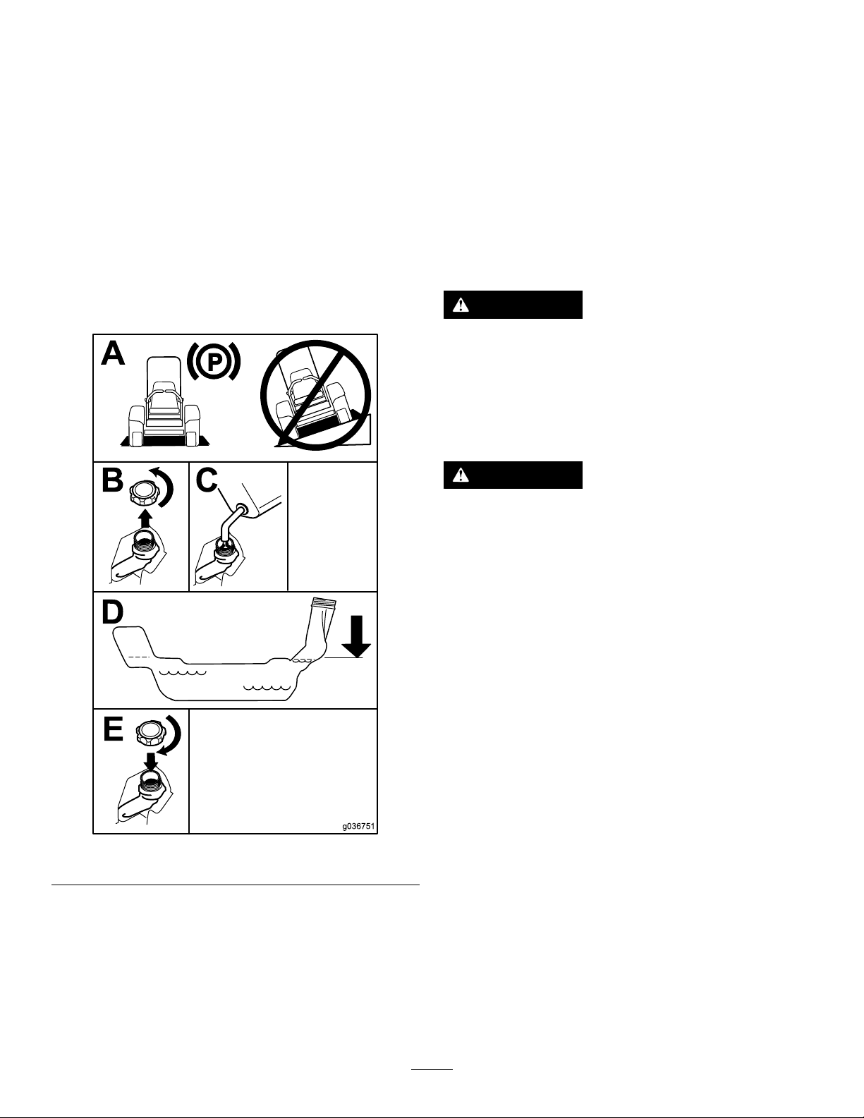
FillingtheFuelTank
1.Parkthemachineonalevelsurface.
2.Engagetheparkingbrake.
3.Shutofftheengineandremovethekey.
4.Cleanaroundthefuel-tankcap.
5.Fillthefueltanktothebottomofthellerneck
(Figure10).
Note:Donotllthefueltankcompletelyfull.
Theemptyspaceinthetankallowsthefuelto
expand.
BreakinginaNewMachine
Newenginestaketimetodevelopfullpower.Mower
decksanddrivesystemshavehigherfrictionwhen
new,placingadditionalloadontheengine.Allow
40to50hoursofbreak-intimefornewmachinesto
developfullpowerandbestperformance.
Usingthe
Rollover-ProtectionSystem
(ROPS)
WARNING
Toavoidinjuryordeathfromrollover,keep
therollbarinthefullyraised,lockedposition
andusetheseatbelt.
Ensurethattheseatissecuredtothe
machine.
Figure10
WARNING
Thereisnorolloverprotectionwhentheroll
barisinthedownposition.
•Lowertherollbaronlywhenabsolutely
necessary.
•Donotweartheseatbeltwhentherollbar
isinthedownposition.
•Driveslowlyandcarefully.
•Raisetherollbarassoonasclearance
permits.
•Checkcarefullyforoverheadclearances
(i.e.,branches,doorways,electricalwires)
beforedrivingunderanyobjectsanddo
notcontactthem.
LoweringtheRollBar
g036751
Important:Lowertherollbaronlywhen
absolutelynecessary.
1.T olowertherollbar,applyforwardpressureto
theupperpartoftherollbar.
PerformingDaily
Maintenance
Beforestartingthemachineeachday ,performthe
EachUse/DailyprocedureslistedinMaintenance
(page40).
2.Pullbothknobsoutandrotatethem90degrees
sothattheyarenotengaged(Figure1 1).
3.Lowertherollbartothedownposition(Figure
11).
21
Page 22
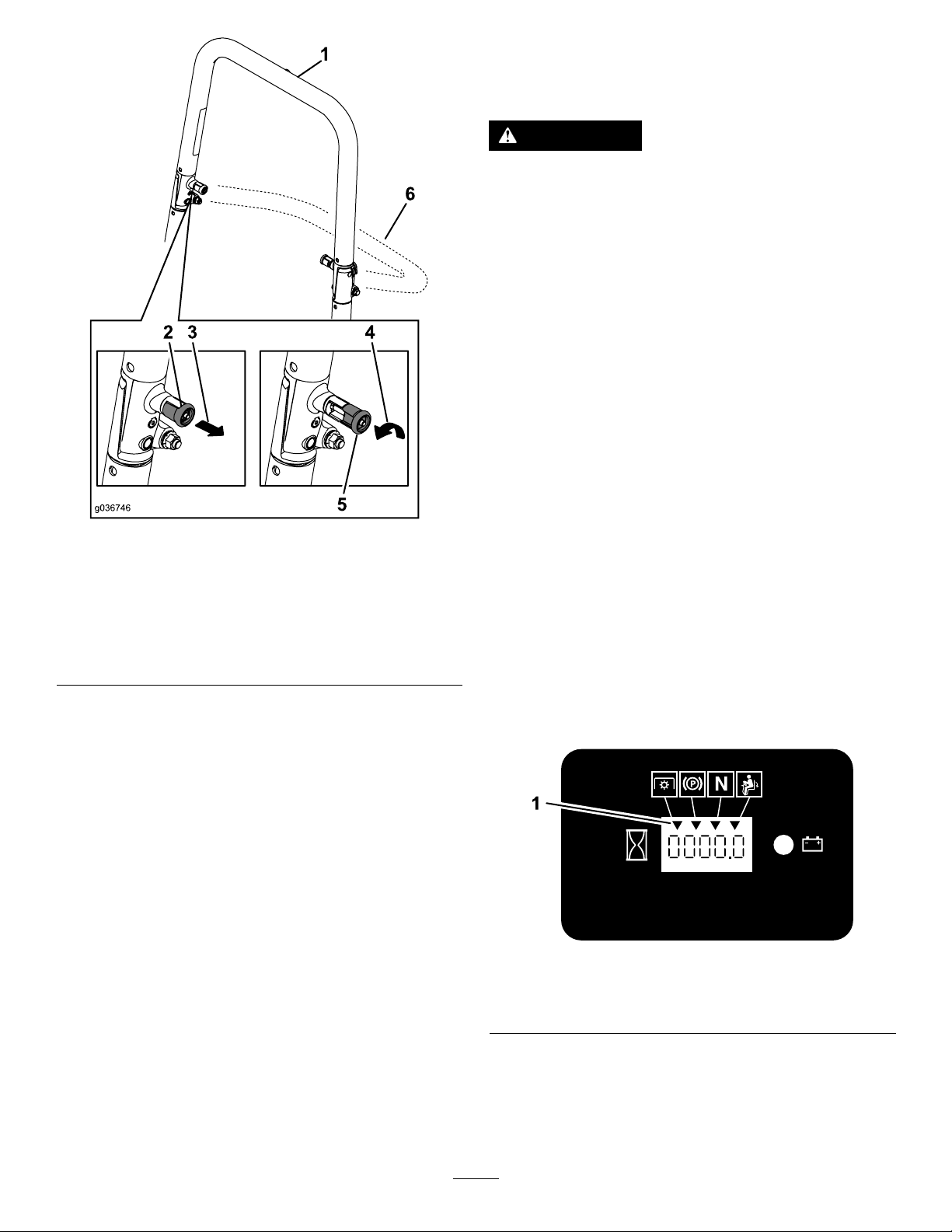
Figure11
UsingtheSafety-Interlock
System
WARNING
Ifthesafety-interlockswitchesare
disconnectedordamaged,themachinecould
operateunexpectedly,causingpersonal
injury.
•Donottamperwiththeinterlockswitches.
•Checktheoperationoftheinterlock
switchesdailyandreplaceanydamaged
switchesbeforeoperatingthemachine.
Understandingthe
Safety-InterlockSystem
Thesafety-interlocksystemisdesignedtopreventthe
enginefromstartingunlessthefollowingoccurs:
•Theparkingbrakeisengaged.
•Theblade-controlswitch(PTO)isdisengaged.
g036746
•Themotion-controlleversareintheNEUTRAL-LOCK
position.
1.Rollbarintheupright
position
2.ROPSknobinthelatched
position
3.PulltheROPSknobout.6.Rollbarinthefolded
4.RotatetheROPSknob90
degrees.
5.ROPSknobinthe
unlatchedposition
position
RaisingtheRollBar
Important:Alwaysusetheseatbeltwiththeroll
barintheraisedposition.
1.Raisetherollbartotheoperatingpositionand
rotatetheknobsuntiltheymovepartiallyinto
thegrooves(Figure11).
2.Raisetherollbartothefulluprightpositionwhile
pushingontheupperrollbarsothatthepins
snapintopositionwhentheholesalignwiththe
pins(Figure11).
3.Pushontherollbarandensurethatbothpins
areengaged.
Thesafety-interlocksystemalsoisdesignedtoshut
offtheenginewhenthemotion-controlleversare
movedfromtheNEUTRAL-LOCKpositionwiththe
parkingbrakeengagedorifyourisefromtheseat
whenthePTOisengaged.
Thehourmeterhasindicatorstonotifytheuserwhen
theinterlockcomponentisinthecorrectposition.
Whenthecomponentisinthecorrectposition,an
indicatordisplaysonthescreen.
g187670
Figure12
1.Indicatorsdisplaywhentheinterlockcomponentsareinthe
correctposition
TestingtheSafety-Interlock
System
ServiceInterval:Beforeeachuseordaily
22
Page 23
Testthesafety-interlocksystembeforeyouusethe
machineeachtime.Ifthesafetysystemdoesnot
operateasdescribedbelow,haveanAuthorized
ServiceDealerrepairthesafetysystemimmediately .
1.Sitontheseat,engagetheparkingbrake,and
movetheblade-controlswitch(PTO)totheON
position.Trystartingtheengine;theengine
shouldnotstart.
2.Sitontheseat,engagetheparkingbrake,and
movetheblade-controlswitch(PTO)totheOFF
position.Moveeithermotion-controlleverout
oftheNEUTRAL-LOCKposition.Trystartingthe
engine;theengineshouldnotstart.Repeatfor
theothercontrollever.
3.Sitontheseat,engagetheparkingbrake,
movetheblade-controlswitch(PTO)totheOFF
position,andmovethemotion-controllevers
totheNEUTRAL-LOCKposition.Nowstartthe
engine.Whiletheengineisrunning,disengage
theparkingbrake,engagetheblade-control
switch(PTO),andriseslightlyfromtheseat;the
engineshouldshutoff.
4.Sitontheseat,engagetheparkingbrake,
movetheblade-controlswitch(PTO)totheOFF
position,andmovethemotion-controllevers
totheNEUTRAL-LOCKposition.Nowstartthe
engine.Whiletheengineisrunning,center
eithermotioncontrolandmove(forwardor
reverse);theengineshouldshutoff.Repeatfor
othermotioncontrol.
5.Sitontheseat,disengagetheparkingbrake,
movetheblade-controlswitch(PTO)totheOFF
position,andmovethemotion-controllevers
totheNEUTRAL-LOCKposition.Trystartingthe
engine;theengineshouldnotstart.
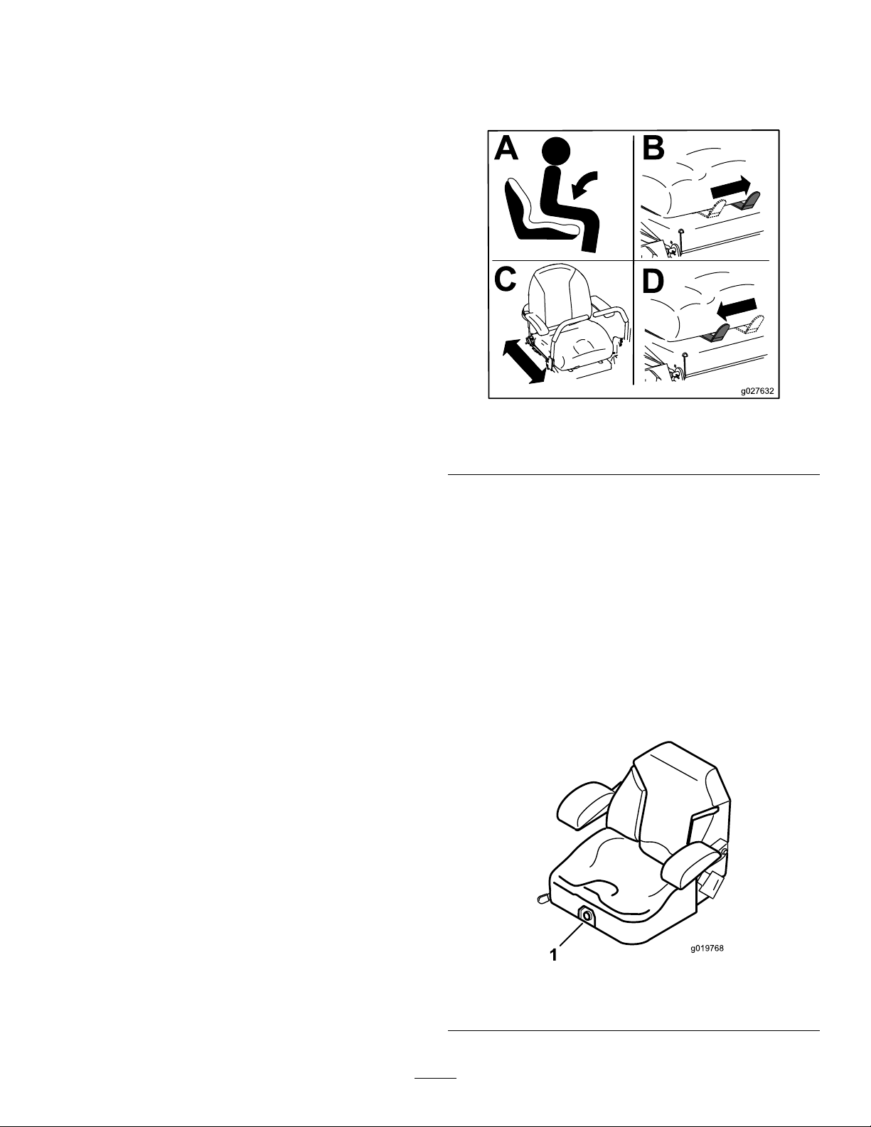
PositioningtheSeat
Theseatcanmoveforwardandbackward(Figure13).
Positiontheseatwhereyouhavethebestcontrolof
themachineandaremostcomfortable.
g027632
Figure13
SeatformachineswithMyRideshown.
ChangingtheSeat
Suspension
MachineswithoutMyRide™
SuspensionSystemOnly
Theseatisadjustabletoprovideasmoothand
comfortableride.Positiontheseatwhereyouare
mostcomfortable.
Toadjustit,turntheknobinfronteitherdirectionto
providethebestcomfort(Figure14).
Figure14
1.Seat-suspensionknob
23
g019768
Page 24
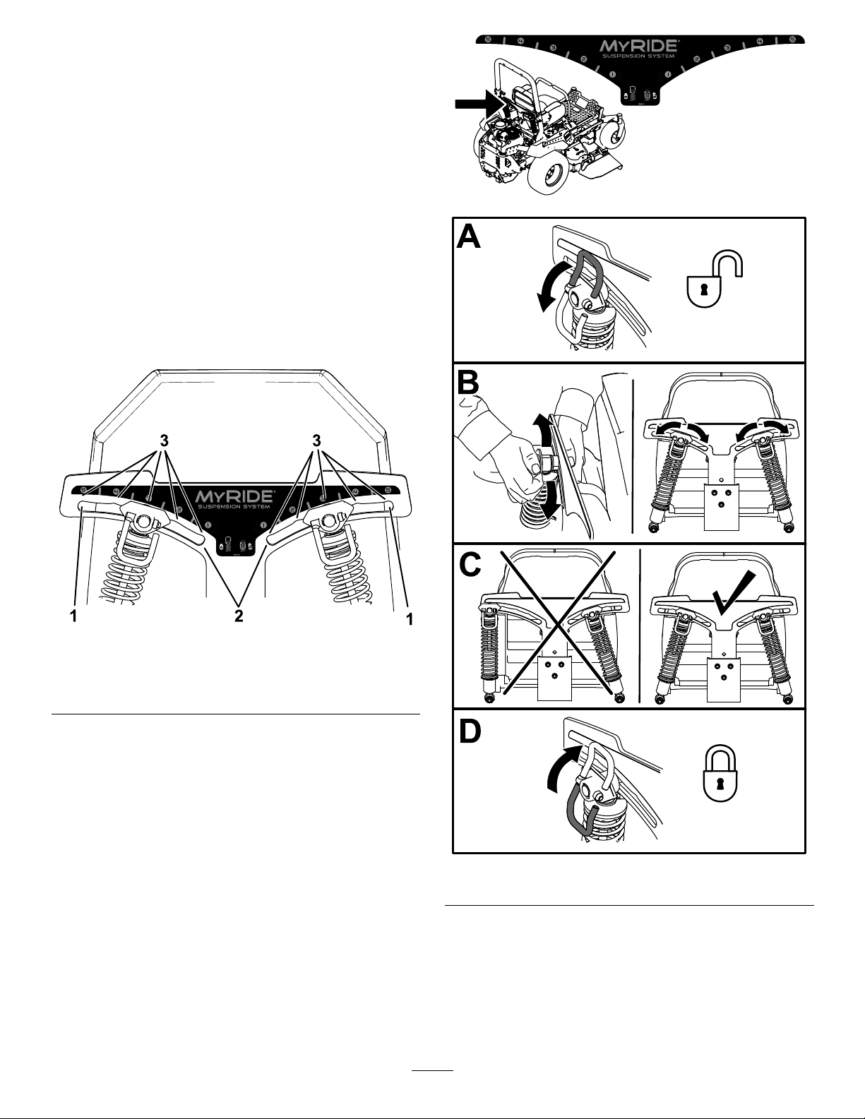
AdjustingtheRear-Shock
Assemblies
MachineswithMyRide™
SuspensionSystemOnly
TheMyRide™suspensionsystemadjuststoprovide
asmoothandcomfortableride.Youcanadjustthe
rear2-shockassembliestoquicklyandeasilychange
thesuspensionsystem.Positionthesuspension
systemwhereyouaremostcomfortable.
Theslotsfortherear-shockassemblieshave
detentpositionsforreference.Youcanpositionthe
rear-shockassembliesanywhereintheslot,notjustin
thedetentpositions.Thefollowinggraphicshowsthe
positionforasoftorrmrideandthedifferentdetent
positions(Figure15).
g227752
Figure15
1.Firmestposition3.Detentsintheslots
2.Softestposition
Note:Ensurethattheleftandrightrear-shock
assembliesarealwaysadjustedtothesamepositions.
Adjusttherear-shockassemblies(Figure16).
g227753
g227751
Figure16
24
Page 25
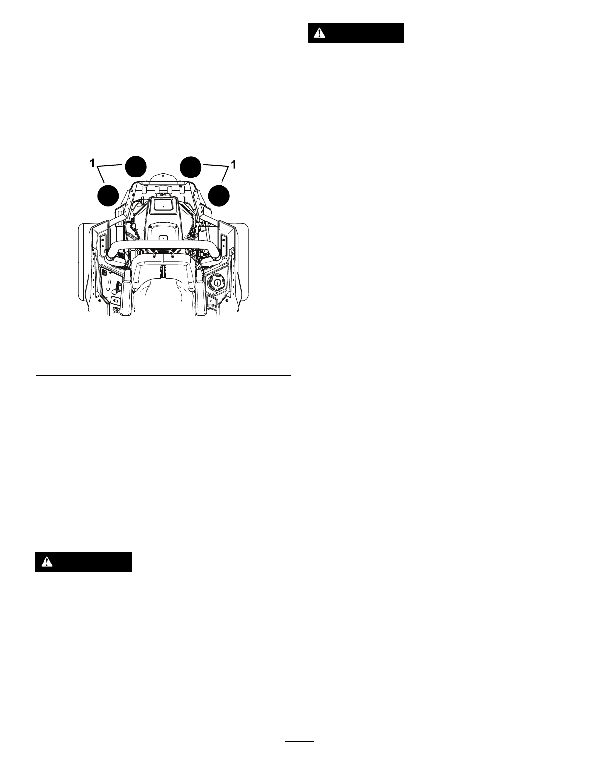
UsingAttachmentsand
WARNING
Accessories
UseonlyToroapprovedattachmentsandaccessories.
Ifyouaddmorethan1accessory-mountkit(i.e.,
bucketkitoruniversalmountkit)isaddedtoanyof
the4locationsshowninFigure17,addafront-weight
kit.ContactanAuthorizedServiceDealerforthe
front-weightkit.
Figure17
1.Addafront-weightkitwhen2ormoreaccessory-mountkits
areinstalledatthesepositions.
Engineexhaustcontainscarbonmonoxide,
whichisanodorlessdeadlypoisonthatcan
killyou.
DoNotrunengineindoorsorinasmall
connedareawheredangerouscarbon
monoxidefumescancollect.
•Theowner/usercanpreventandisresponsible
foraccidentsorinjuriesoccurringtohimselfor
herself,otherpeopleorproperty .
•Thismowerwasdesignedforoneoperatoronly .
Donotcarrypassengersandkeepallothersaway
frommachineduringoperation.
•Donotoperatethemachinewhileill,tired,or
undertheinuenceofalcoholordrugs.
•Operateonlyindaylightorgoodarticiallight.
•Lightningcancausesevereinjuryordeath.If
lightningisseenorthunderisheardinthearea,
DoNotoperatethemachine;seekshelter.
g037417
•Useextracarewhileoperatingwithaccessoriesor
attachments,suchasgrasscollectionsystems.
Thesecanchangethestabilityofthemachine
andcausealossofcontrol.Followdirectionsfor
counterweightsifrequired.
DuringOperation
DuringOperationSafety
GeneralSafety
Theoperatormustusetheirfullattentionwhen
operatingthemachine.DoNotengageinanyactivity
thatcausesdistractions;otherwise,injuryorproperty
damagemayoccur.
WARNING
Operatingengineparts,especiallythemufer,
becomeextremelyhot.Severeburnscan
occuroncontactanddebris,suchasleaves,
grass,brush,etc.cancatchre.
•Allowengineparts,especiallythemufer,
tocoolbeforetouching.
•Removeaccumulateddebrisfrommufer
andenginearea.
•Keepawayfromholes,ruts,bumps,rocks,and
otherhiddenhazards.Usecarewhenapproaching
blindcorners,shrubs,trees,tallgrassorother
objectsthatmayhideobstaclesorobscurevision.
Uneventerraincouldoverturnthemachineor
causetheoperatortolosetheirbalanceorfooting.
•Besurealldrivesareinneutralandparkingbrake
isengagedbeforestartingengine.Useseatbelts
withtherollbarintheraisedandlockedposition.
•Starttheenginecarefullyaccordingtoinstructions
withfeetwellawayfromtheblades.
•Neveroperatethemowerwithdamagedguards,
shields,orcovers.Alwayshavesafetyshields,
guards,switchesandotherdevicesinplaceandin
properworkingcondition.
•Keepclearofthedischargeopeningatalltimes.
Nevermowwiththedischargedoorraised,
removedoralteredunlessthereisagrass
collectionsystemormulchkitinplaceandworking
properly.
•Keephandsandfeetawayfrommovingparts.
Ifpossible,DoNotmakeadjustmentswiththe
enginerunning.
25
Page 26

WARNING
Hands,feet,hair,clothing,oraccessories
canbecomeentangledinrotatingparts.
Contactwiththerotatingpartscan
causetraumaticamputationorsevere
lacerations.
–DoNotoperatethemachinewithout
guards,shields,andsafetydevicesin
placeandworkingproperly.
–Keephands,feet,hair,jewelry ,or
clothingawayfromrotatingparts.
•Neverraisethedeckwithbladesrunning.
•Beawareofthemowerdischargepathanddirect
dischargeawayfromothers.Avoiddischarging
materialagainstawallorobstructionasthe
materialmayricochetbacktowardtheoperator.
Stoptheblades,slowdown,andusecautionwhen
crossingsurfacesotherthangrassandwhen
transportingthemowertoandfromtheareatobe
mowed.
•Bealert,slowdownandusecautionwhen
makingturns.Lookbehindandtothesidebefore
changingdirections.DoNotmowinreverse
unlessabsolutelynecessary.
•DoNotchangetheenginegovernorsettingor
overspeedtheengine.
•Parkthemachineonlevelground.Stopengine,
waitforallmovingpartstostop,andremovethe
sparkplugwire(s).
–Beforechecking,cleaningorworkingonthe
mower.
–Afterstrikingaforeignobjectorabnormal
vibrationoccurs(inspectthemowerfor
damageandmakerepairsbeforerestarting
andoperatingthemower).
–Beforeclearingblockages.
–Wheneveryouleavethemower.DoNotleave
arunningmachineunattended.
•Stopengine,waitforallmovingpartstostop:
–Beforerefueling.
–Beforedumpingthegrasscatcher.
–Beforemakingheightadjustments.
•Tragicaccidentscanoccuriftheoperatorisnot
alerttothepresenceofchildren.Childrenare
oftenattractedtothemachineandthemowing
activity.Neverassumethatchildrenwillremain
whereyoulastsawthem.
–Keepchildrenoutofthemowingareaand
underthewatchfulcareofanotherresponsible
adult,nottheoperator.
–Bealertandturnthemachineoffifchildren
enterthearea.
–Beforeandwhilebackingorchangingdirection,
lookbehind,down,andside-to-sideforsmall
children.
–Neverallowchildrentooperatethemachine.
–DoNotcarrychildren,evenwiththeblades
shutoff.Childrencouldfalloffandbeseriously
injuredorinterferewiththesafeoperationof
themachine.Childrenthathavebeengiven
ridesinthepastcouldsuddenlyappearinthe
workingareaforanotherrideandberunover
orbackedoverbythemachine.
SlopeSafety
•Slopesareamajorfactorrelatedtolossofcontrol
androlloveraccidents,whichcanresultinsevere
injuryordeath.Theoperatorisresponsiblefor
safeslopeoperation.Operatingthemachineon
anysloperequiresextracaution.Beforeusingthe
machineonaslope,theoperatormust:
–Reviewandunderstandtheslopeinstructions
inthemanualandonthemachine.
–Useanangleindicatortodeterminethe
approximateslopeangleofthearea.
–Neveroperateonslopesgreaterthan15
degrees.
–Evaluatethesiteconditionsofthedayto
determineiftheslopeissafeformachine
operation.Usecommonsenseandgood
judgmentwhenperformingthisevaluation.
Changesintheterrain,suchasmoisture,can
quicklyaffecttheoperationofthemachineon
aslope.
•Identifyhazardsatthebaseoftheslope.Do
Notoperatethemachineneardropoffs,ditches,
embankments,waterorotherhazards.The
machinecouldsuddenlyrolloverifawheelgoes
overtheedgeortheedgecollapses.Keepasafe
distance(twicethewidthofthemachine)between
themachineandanyhazard.Useawalkbehind
machineorahandtrimmertomowthegrassin
theseareas.
26
Page 27
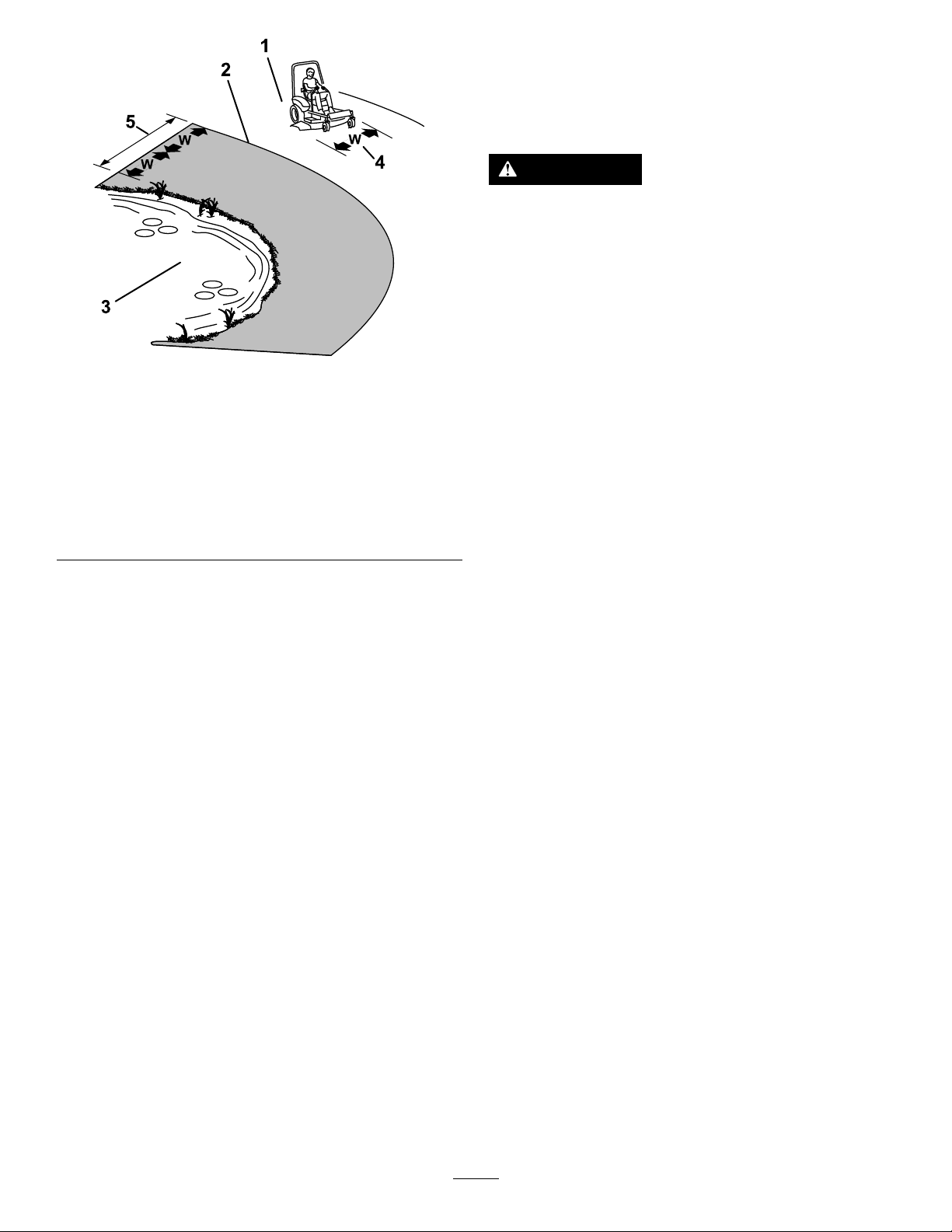
Figure18
1.SafeZone-Usethemowerhereonslopeslessthan15
degrees
2.DangerZone-Useawalk-behindmowerand/orhand
trimmeronslopesgreaterthan15degrees
3.Water
4.W=widthofthemachine
5.Keepasafedistance(twicethewidthofthemachine)
betweenthemachineandanyhazard.
RolloverProtectionSystem
(ROPS)Safety
ARolloverProtectionSystem(rollbar)isinstalledon
themachine.
WARNING
Thereisnorolloverprotectionwhentheroll
barisdown.Wheelsdroppingoveredges,
ditches,steepbanks,orwatercancause
rollovers,whichmayresultinseriousinjury,
deathordrowning.
•DoNotremovetheROPS.
•Keeptherollbarintheraisedandlocked
g221745
positionanduseseatbelt.
•Lowertherollbaronlywhenabsolutely
necessary.
•DoNotwearseatbeltwhentherollbaris
down.
•Driveslowlyandcarefully.
•Raisetherollbarassoonasclearance
permits.
•Avoidstarting,stoppingorturningthemachineon
slopes.Avoidmakingsuddenchangesinspeedor
direction;turnslowlyandgradually.
•DoNotoperateamachineunderanyconditions
wheretraction,steeringorstabilityisinquestion.
Beawarethatoperatingthemachineonwet
grass,acrossslopesordownhillmaycausethe
machinetolosetraction.Lossoftractiontothe
drivewheelsmayresultinslidingandalossof
brakingandsteering.Themachinecanslideeven
ifthedrivewheelsarestopped.
•Removeormarkobstaclessuchasditches,holes,
ruts,bumps,rocksorotherhiddenhazards.T all
grasscanhideobstacles.Uneventerraincould
overturnthemachine.
•Useextracarewhileoperatingwithaccessoriesor
attachments,suchasgrasscollectionsystems.
Thesecanchangethestabilityofthemachine
andcausealossofcontrol.Followdirectionsfor
counterweights.
•Ifpossible,keepthedeckloweredtotheground
whileoperatingonslopes.Raisingthedeckwhile
operatingonslopescancausethemachineto
becomeunstable.
•Becertainthattheseatbeltcanbereleased
quicklyintheeventofanemergency.
•Checkcarefullyforoverheadclearances(i.e.
branches,doorways,andelectricalwires)before
drivingunderanyobjectsandDoNotcontact
them.
•Intheeventofarollover,taketheunittoan
AuthorizedServiceDealertohavetheROPS
inspected.
•ReplaceadamagedROPS.DoNotrepairor
revise.
•Anyaccessories,alterations,orattachments
addedtotheROPSmustbeapprovedbyT oro.
EnteringtheOperator’s
Position
Usethemowerdeckasasteptogetintothe
operator’sposition(Figure19).
27
Page 28
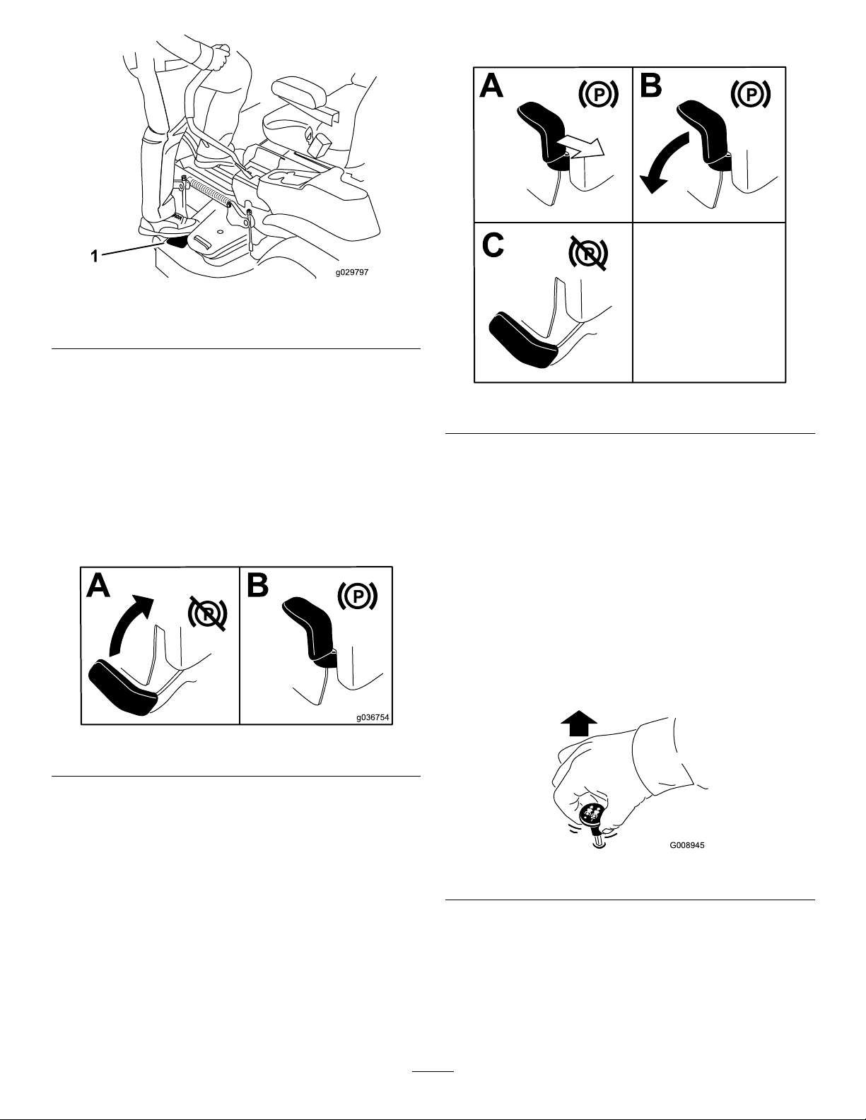
1.Stephere.
DisengagingtheParkingBrake
g029797
Figure19
OperatingtheParking
Brake
Alwaysengagetheparkingbrakewhenyoustopthe
machineorleaveitunattended.
EngagingtheParkingBrake
Parkthemachineonalevelsurface.
Figure20
g192635
Figure21
OperatingtheMower
Blade-ControlSwitch(PTO)
Theblade-controlswitch(PTO)startsandstopsthe
mowerbladesandanypoweredattachments.
EngagingtheBlade-Control
Switch(PTO)
Note:Engagingtheblade-controlswitch(PTO)with
thethrottlepositionathalforlesscausesexcessive
weartothedrivebelts.
g036754
g008945
Figure22
28
Page 29

DisengagingtheBlade-Control
Switch(PTO)
Figure23
OperatingtheThrottle
YoucanmovethethrottlecontrolbetweenFASTand
SLOWpositions(Figure24).
AlwaysusetheFASTpositionwhenengagingthePTO.
OperatingtheChoke
Usethechoketostartacoldengine.
1.Pullupthechokeknobtoengagethechoke
beforeusingthekeyswitch(Figure25).
2.Pushdownthechokeknobtodisengagethe
chokeaftertheenginehasstarted(Figure25).
g009174
Figure24
g008959
Figure25
g008946
1.ONposition2.OFFposition
29
Page 30

StartingtheEngine
ShuttingOfftheEngine
Note:Awarmorhotenginemaynotrequirechoking.
Important:Donotengagethestarterformore
than5secondsatatime.Engagingthestarter
motorformorethan5secondscandamagethe
startermotor.Iftheenginefailstostart,wait10
secondsbeforeoperatingtheenginestarteragain.
Note:RefertoFigure45todeterminewhichengine
youhave.
CAUTION
Childrenorbystandersmaybeinjuredifthey
moveorattempttooperatethemachinewhile
itisunattended.
Alwaysremovethekeyandengagethe
parkingbrakewhenleavingthemachine
unattended.
ShuttingOffKawasakiEngines
Lettheengineidleatslowthrottlefor60seconds
beforeturningtheswitchoff.
Figure26
g227548
g036839
Figure27
Important:Makesurethatthefuel-shutoff
valveisclosedbeforetransportingorstoring
themachinetopreventfuelleakage.Engage
theparkingbrakebeforetransporting.Remove
thekeyasthefuelpumpmayrunandcausethe
batterytolosecharge.
30
Page 31

ShuttingOffKohlerEngines
ShuttingOffToroEngines
Lettheengineidleatmid-throttlefor60seconds
beforeturningtheswitchoff.
Note:EnsurethethrottleisintheFASTposition
beforeshuttingofftheengine.
Figure28
Important:Makesurethatthefuel-shutoff
valveisclosedbeforetransportingorstoring
themachinetopreventfuelleakage.Engage
theparkingbrakebeforetransporting.Remove
thekeyasthefuelpumpmayrunandcausethe
batterytolosecharge.
g231028
Figure29
g037049
Important:Makesurethatthefuel-shutoff
valveisclosedbeforetransportingorstoring
themachinetopreventfuelleakage.Engage
theparkingbrakebeforetransporting.Remove
thekeyasthefuelpumpmayrunandcausethe
batterytolosecharge.
31
Page 32

UsingtheMotion-Control
WARNING
Levers
Themachinecanspinveryrapidly.You
maylosecontrolofthemachineandcause
personalinjuryordamagetothemachine.
•Usecautionwhenmakingturns.
•Slowthemachinedownbeforemaking
sharpturns.
DrivingForward
Note:Theengineshutsoffwhenyoumovethe
traction-controlwiththeparkingbrakeengaged.
Tostopthemachine,pullthemotion-controllevers
totheNEUTRALposition.
1.Disengagetheparkingbrake;referto
DisengagingtheParkingBrake(page28).
2.Movetheleverstothecenter,unlockedposition.
3.T ogoforward,slowlypushthemotion-control
leversforward(Figure31).
c:\data\documentum\checkout\g004532
Figure30
1.Motion-control
lever—NEUTRAL-LOCK
position
2.Center,unlockedposition5.Frontofmachine
3.Forward
4.Backward
DrivingtheMachine
Thedrivewheelsturnindependently,poweredby
hydraulicmotorsoneachaxle.Youcanturn1side
inreversewhileyouturntheotherforward,causing
themachinetospinratherthanturn.Thisgreatly
improvesthemachinemaneuverabilitybutmay
requiresometimeforyoutoadapttohowitmoves.
Thethrottlecontrolregulatestheenginespeedas
measuredinrpm(revolutionsperminute).Place
thethrottlecontrolintheFASTpositionforbest
performance.Alwaysoperateinthefullthrottle
positionwhenmowing.
g008952
Figure31
DrivingBackward
1.Movetheleverstothecenter,unlockedposition.
2.T ogobackward,slowlypullthemotion-control
leversrearward(Figure32).
32
Page 33

Figure32
UsingtheSideDischarge
Themowerhasahingedgrassdeectorthat
dispersesclippingstothesideanddowntowardthe
turf.
DANGER
Withoutagrassdeector,dischargecover,or
acompletegrass-catcherassemblymounted
inplace,youandothersareexposedtoblade
contactandthrowndebris.Contactwith
rotatingmowerblade(s)andthrowndebris
willcauseinjuryordeath.
•Neverremovethegrassdeectorfromthe
mowerdeckbecausethegrassdeector
routesmaterialdowntowardtheturf.Ifthe
g008953
grassdeectoriseverdamaged,replaceit
immediately.
•Neverputyourhandsorfeetunderthe
mowerdeck.
•Nevertrytoclearthedischargearea
ormowerbladesunlessyoumovethe
blade-controlswitch(PTO)totheOFF
position,rotatethekeyswitchtotheOFF
position,andremovethekeyfromthekey
switch.
•Makesurethatthegrassdeectorisinthe
downposition.
AdjustingtheHeightofCut
UsingtheTransportLock
Thetransportlockhas2positions,andisusedwith
thedeck-liftpedal.ThereisaLOCKpositionand
anUNLOCKpositionforthetransportpositionofthe
mowerdeck(Figure33).
33
Page 34

4.Selectaholeintheheight-of-cutbracket
correspondingtotheheight-of-cutdesired,and
insertthepin(Figure34).
5.Pushonthedecklift,pulluponthetransport
lockknob,andslowlylowerthemowerdeck.
Figure34
1.Deck-liftpedal3.Height-of-cutpin
2.Height-of-cutholes
4.Transportlockknob
g036745
Figure33
Transport-LockPositions
1.Transportlockknob3.UNLOCKposition—The
mowerdeckdoesnotlock
intothetransportposition.
2.LOCKposition—The
mowerdecklocksintothe
transportposition.
AdjustingtheHeight-of-CutPin
Adjusttheheight-of-cutfrom38to127mm(1-1/2to5
inches)in6mm(1/4inch)incrementsbymovingthe
height-of-cutpinintodifferentholelocations.
1.MovethetransportlocktotheLOCKposition.
2.Pushonthedeck-liftpedalwithyourfootand
raisethemowerdecktotheTRANSPORTposition
(alsothe127mmor5inchcutting-height
position)asshowninFigure34.
AdjustingtheAnti-Scalp
Rollers
Wheneveryouchangetheheightofcut,adjustthe
g037050
heightoftheanti-scalprollers.
Note:Adjusttheanti-scalprollerssothattherollers
donottouchthegroundinnormal,atmowingareas.
1.Parkthemachineonalevelsurface,disengage
theblade-controlswitchandengagetheparking
brake.
2.Shutofftheengine,removethekey ,andwait
forallmovingpartstostopbeforeleavingthe
operatingposition.
3.Adjusttheanti-scalprollersasshowninFigure
35orFigure36.
3.Removethepinfromtheheight-of-cutbracket
(Figure34).
34
Page 35

Figure35
2500Seriesmowerdeckshown
1.Anti-scalproller4.Flangenut
2.Spacer
3.Bushing
5.Bolt
AdjustingtheSideBumpers
Rear-DischargeMachinesOnly
Installthesidebumpersinthetopholeswhen
operatinginaheightofcuthigherthan64mm(2-1/2
inches)andinthecenterholeswhenoperatingina
heightofcutlowerthan64mm(2-1/2inches).
Note:Whenthebumpersbecomeworn,switchthe
bumperstotheoppositesidesofthemowerandip
themover.Thisallowsyoutousethebumperslonger
g038079
beforereplacingthem.
1.Parkthemachineonalevelsurface,disengage
theblade-controlswitchandengagetheparking
brake;refertoEngagingtheParkingBrake
(page28).
2.Shutofftheengine,removethekey ,andwait
forallmovingpartstostopbeforeleavingthe
operatingposition.
3.Raisethemowertothetransportposition.
4.Removetheboltsandnutsfromeachbumper
(Figure37).
Figure36
1500and2000Seriesmowerdeckshown
1.Flangenut4.Anti-scalproller
2.Bolt
3.Bushing
5.Spacer
g036848
g037862
Figure37
1.Bolt(3)3.Nut(3)
2.Bumper
5.Moveeachbumpertothedesiredpositionand
securethemwiththeboltsandnuts.
Note:Useonlythetoporcentersetsofholes
toadjustthebumpers.Youusethebottom
holeswhenswitchingsides,atwhichtimethey
becomethetopholesontheothersideofthe
mower.
35
Page 36

OperatingTips
UsingtheFastThrottleSetting
dropontoyourlawn.Toavoidthis,moveontoa
previouslycutareawiththebladesengagedoryou
candisengagethemowerdeckwhilemovingforward.
Forbestmowingandmaximumaircirculation,operate
theengineattheFASTposition.Airisrequiredto
thoroughlycutgrassclippings,sodonotsetthe
height-of-cutsolowastototallysurroundthemower
deckinuncutgrass.Alwaystrytohave1sideofthe
mowerdeckfreefromuncutgrass,whichallowsair
tobedrawnintothemowerdeck.
CuttingaLawnfortheFirstTime
Cutgrassslightlylongerthannormaltoensurethat
thecuttingheightofthemowerdeckdoesnotscalp
anyunevenground.However,thecuttingheight
usedinthepastisgenerallythebestonetouse.
Whencuttinggrasslongerthan15cm(6inches)tall,
youmaywanttocutthelawntwicetoensurean
acceptablequalityofcut.
CuttingaThirdoftheGrassBlade
Itisbesttocutonlyaboutathirdofthegrassblade.
Cuttingmorethanthatisnotrecommendedunless
grassissparse,oritislatefallwhengrassgrows
moreslowly.
KeepingtheUndersideofthe
MowerDeckClean
Cleanclippingsanddirtfromtheundersideofthe
mowerdeckaftereachuse.Ifgrassanddirtbuildup
insidethemowerdeck,cuttingqualitywilleventually
becomeunsatisfactory.
MaintainingtheBlade(s)
Maintainasharpbladethroughoutthecuttingseason
becauseasharpbladecutscleanlywithouttearingor
shreddingthegrassblades.Tearingandshredding
turnsgrassbrownattheedges,whichslowsgrowth
andincreasesthechanceofdisease.Checkthe
mowerbladesaftereachuseforsharpness,and
foranywearordamage.Filedownanynicksand
sharpenthebladesasnecessary .Ifabladeis
damagedorworn,replaceitimmediatelywitha
genuineT ororeplacementblade.
AfterOperation
AlternatingtheMowingDirection
Alternatethemowingdirectiontokeepthegrass
standingstraight.Thisalsohelpsdisperseclippings,
whichenhancesdecompositionandfertilization.
MowingatCorrectIntervals
Grassgrowsatdifferentratesatdifferenttimesof
theyear.Tomaintainthesamecuttingheight,mow
moreofteninearlyspring.Asthegrassgrowthrate
slowsinmidsummer,mowlessfrequently.Ifyou
cannotmowforanextendedperiod,rstmowata
highcuttingheight,thenmowagain2dayslaterata
lowerheightsetting.
UsingaSlowerCuttingSpeed
Toimprovecutquality ,useaslowergroundspeed
incertainconditions.
AvoidingCuttingTooLow
Whenmowinguneventurf,raisethecuttingheight
toavoidscalpingtheturf.
AfterOperationSafety
GeneralSafety
•Parkmachineonlevelground,disengagedrives,
setparkingbrake,stopengine,removekeyor
disconnectsparkplugwire.Waitforallmovement
tostopandallowthemachinetocoolbefore
adjusting,cleaning,repairing,orstoring.Never
allowuntrainedpersonneltoservicemachine.
•CleanthemachineasstatedintheMaintenance
section.Keepengineandengineareafreefrom
accumulationofgrass,leaves,excessivegrease
oroil,andotherdebriswhichcanaccumulate
intheseareas.Thesematerialscanbecome
combustibleandmayresultinare.
•Frequentlycheckforwornordeteriorating
componentsthatcouldcreateahazard.Tighten
loosehardware.
StoppingtheMachine
Ifyoumuststoptheforwardmotionofthemachine
whilemowing,aclumpofgrassclippingsmay
36
Page 37

UsingtheFuel-Shutoff
WARNING
Valve
Closethefuel-shutoffvalvefortransport,maintenance,
andstorage(Figure38).
Ensurethatthefuel-shutoffvalveisopenwhen
startingtheengine.
Theengineandhydraulic-driveunitscan
becomeveryhot.Touchingahotengineor
hydraulic-driveunitscancausesevereburns.
Allowtheengineandhydraulic-driveunits
tocoolcompletelybeforeaccessingthe
drive-wheelreleasevalves.
Thedrive-wheelreleasevalvesarelocatedontheleft
andrightsidesunderneaththeenginedeck.
1.Parkthemachineonalevelsurface,disengage
theblade-controlswitch,andengagetheparking
brake.
2.Shutofftheengine,removethekey ,andwait
g036849
forallmovingpartstostopbeforeleavingthe
operatingposition.
3.Locatethebypassleversbehindtheseat,down
ontheleftandrightsideoftheframe.
4.T opushthemachine,movebothbypassknobs
rearwardandlockthemintoplace(Figure39).
5.Disengagetheparkingbrakebeforepushing
themachine.
Figure38
1.ONposition2.OFFposition
UsingtheDrive-Wheel
ReleaseValves
WARNING
Handsmaybecomeentangledintherotating
drivecomponentsbelowtheenginedeck,
whichcouldresultinseriousinjury.
Shutofftheengine,removethekey,andallow
allmovingpartstostopbeforeaccessingthe
drive-wheelreleasevalves.
g008948
g035062
Figure39
1.Frontofthemachine
2.Rotatebypassreleaseknobcounterclockwisetoloosen.
3.Leverpositionforoperatingthemachine
4.Pulltheleverinthisdirectiontopushthemachine.
5.Leverpositionforpushingthemachine
6.Rotatethebypass-releaseknobclockwisetotighten.
7.Engine
8.Releaselever
37
Page 38

6.T orunthemachine,movethebypassknobsto
theFORWARDpositionandlockthemintoplace
(Figure39).
TransportingtheMachine
Useaheavy-dutytrailerortrucktotransportthe
machine.Useafull-widthramp.Ensurethatthetrailer
ortruckhasallthenecessarybrakes,lighting,and
markingasrequiredbylaw.Pleasecarefullyreadall
thesafetyinstructions.Knowingthisinformationcould
helpyouorbystandersavoidinjury.Refertoyour
localordinancesfortrailerandtie-downrequirements.
WARNING
Drivingonthestreetorroadwaywithout
turnsignals,lights,reectivemarkings,ora
slow-moving-vehicleemblemisdangerous
andcanleadtoaccidents,causingpersonal
injury.
Donotdrivethemachineonapublicstreet
orroadway.
SelectingaTrailer
WARNING
Loadingamachineontoatrailerortruck
increasesthepossibilityoftip-overandcould
causeseriousinjuryordeath(Figure40).
•Useonlyafull-widthramp;donotuse
individualrampsforeachsideofthe
machine.
•Donotexceeda15-degreeanglebetween
therampandthegroundorbetweenthe
rampandthetrailerortruck.
•Ensurethatthelengthoftherampisat
least4timesaslongastheheightofthe
trailerortruckbedtotheground.This
ensuresthattherampangledoesnot
exceed15degreesonatground.
Figure40
1.Full-widthrampinstowed
position
2.Sideviewoffull-width
rampinloadingposition
3.Notgreaterthan
15degrees
4.Rampisatleast4times
aslongastheheightof
thetrailerortruckbedto
theground
5.H=heightofthetraileror
truckbedtotheground
6.Trailer
LoadingtheMachine
WARNING
Loadingamachineontoatrailerortruck
increasesthepossibilityoftip-overandcould
causeseriousinjuryordeath.
•Useextremecautionwhenoperatinga
machineonaramp.
g027996
•Backthemachineuptherampanddriveit
forwarddowntheramp.
•Avoidsuddenaccelerationordeceleration
whiledrivingthemachineonarampas
thiscouldcausealossofcontrolora
tip-oversituation.
38
Page 39

1.Ifusingatrailer,connectittothetowingvehicle
andconnectthesafetychains.
2.Ifapplicable,connectthetrailerbrakesand
lights.
3.Lowertheramp,ensuringthattheangle
betweentherampandthegrounddoesnot
exceed15degrees(Figure40).
4.Backthemachineuptheramp(Figure41).
Figure41
g028043
1.Backthemachineupthe
ramp.
2.Drivethemachineforward
downtheramp.
5.Shutofftheengine,removethekey,andengage
theparkingbrake.
6.Tiedownthemachinenearthefrontcaster
wheelsandtherearbumperwithstraps,chains,
cable,orropes(Figure42).Refertolocal
regulationsfortie-downrequirements.
Figure42
1.Tie-downloops
UnloadingtheMachine
1.Lowertheramp,ensuringthattheangle
betweentherampandthegrounddoesnot
exceed15degrees(Figure40).
2.Drivethemachineforwarddowntheramp
(Figure41).
g227761
39
Page 40

Maintenance
MaintenanceSafety
WARNING
Whilemaintenanceoradjustmentsarebeing
made,someonecouldstarttheengine.
Accidentalstartingoftheenginecould
seriouslyinjureyouorotherbystanders.
Removethekeyfromtheignitionswitch,
engageparkingbrake,andpullthewire(s)
offthesparkplug(s)beforeyoudoany
maintenance.Alsopushthewire(s)asideso
itdoesnotaccidentallycontactthespark
plug(s).
WARNING
Theenginecanbecomeveryhot.Touchinga
hotenginecancausesevereburns.
Allowtheenginetocoolcompletelybefore
serviceormakingrepairsaroundtheengine
area.
•Parkmachineonlevelground,disengagedrives,
setparkingbrake,stopengine,removekeyor
disconnectsparkplugwire.Waitforallmovement
tostopandallowthemachinetocoolbefore
adjusting,cleaningorrepairing.Neverallow
untrainedpersonneltoservicemachine.
•Disconnectbatteryorremovesparkplugwire
beforemakinganyrepairs.Disconnectthe
negativeterminalrstandthepositivelast.
Reconnectpositiverstandnegativelast.
•Keepthemachine,guards,shieldsandall
safetydevicesinplaceandinsafeworking
condition.Frequentlycheckforwornor
deterioratingcomponentsandreplacethemwith
themanufacturer’srecommendedpartswhen
necessary.
WARNING
Removalormodicationoforiginal
equipment,partsand/oraccessories
mayalterthewarranty ,controllability,
andsafetyofthemachine.Unauthorized
modicationstotheoriginalequipmentor
failuretouseoriginalToropartscouldlead
toseriousinjuryordeath.Unauthorized
changestothemachine,engine,fuelor
ventingsystem,mayviolateapplicable
safetystandardssuchas:ANSI,OSHAand
NFPAand/orgovernmentregulationssuch
asEP AandCARB.
WARNING
Hydraulicuidescapingunderpressure
canpenetrateskinandcauseinjury.Fluid
accidentallyinjectedintotheskinmustbe
surgicallyremovedwithinafewhoursby
adoctorfamiliarwiththisformofinjuryor
gangrenemayresult.
–Ifequipped,makesureallhydraulic
uidhosesandlinesareingood
conditionandallhydraulicconnections
andttingsaretightbeforeapplying
pressuretohydraulicsystem.
–Keepbodyandhandsawayfrom
pinholeleaksornozzlesthatejecthigh
pressurehydraulicuid.
–Usecardboardorpaper,notyourhands,
tondhydraulicleaks.
–Safelyrelieveallpressureinthe
hydraulicsystembyplacingthemotion
controlleversinneutralandshuttingoff
theenginebeforeperforminganywork
onthehydraulicsystem.
WARNING
Fuelsystemcomponentsareunder
highpressure.Theuseofimproper
componentscanresultinsystemfailure,
gasolineleakageandpossibleexplosion.
Useonlyapprovedfuellinesandfuellters
forhighpressuresystems.
•Usecarewhencheckingblades.Wrapthe
blade(s)orweargloves,andusecautionwhen
servicingthem.Onlyreplacedamagedblades.
Neverstraightenorweldthem.
40
Page 41

•Usejackstandstosupportthemachineand/or
componentswhenrequired.
CAUTION
Raisingthemachineforserviceor
maintenancerelyingsolelyonmechanical
orhydraulicjackscouldbedangerous.
Themechanicalorhydraulicjacksmaynot
beenoughsupportormaymalfunction
allowingthemachinetofall,whichcould
causeinjury.
Donotrelysolelyonmechanicalor
hydraulicjacksforsupport.Useadequate
jackstandsorequivalentsupport.
•Carefullyreleasepressurefromcomponentswith
storedenergy.
RecommendedMaintenanceSchedule(s)
•Keephandsandfeetawayfrommovingparts.
Ifpossible,DoNotmakeadjustmentswiththe
enginerunning.Ifthemaintenanceoradjustment
procedurerequiretheenginetoberunningand
componentsmoving,useextremecaution.
WARNING
Contactwithmovingpartsorhotsurfaces
maycausepersonalinjury .
Keepyourngers,hands,andclothing
clearofrotatingcomponentsandhot
surfaces.
•Checkallboltsfrequentlytomaintainproper
tightness.
MaintenanceService
Interval
Aftertherst5hours
Aftertherst75hours
Beforeeachuseordaily
Every25hours
Every25hoursormonthly,
whichevercomesrst
MaintenanceProcedure
•ForToroengines—changetheengineoilandlter.
•Changethehydraulic-systemltersanduid.
•Checkthesafety-interlocksystem.
•ForKawasakiengines—checktheengine-oillevel.
•ForKohlerengines—checktheaircleanerfordirty,loose,ordamagedparts.
•ForKohlerengines—checktheengine-oillevel.
•ForToroengines—checktheengine-oillevel.
•Cleantheblowerhousing(moreoftenunderdusty,dirtyconditions).
•Cleantheairintakescreen.
•Checktheseatbelt.
•Checktherollbarknobs.
•Cleantheenginescreenandtheareaaroundtheengine.
•Cleanaroundtheengine-exhaustsystem.
•Checkthehydraulicuidlevelintheexpansiontank.
•Inspecttheblades.
•Cleanthemowerdeck.
•Cleanthesuspensionsystem.
•For1500and2000Seriesmachines—Greasethefrontcasteraxles(moreoftenin
dirtyordustyconditions).
•ForKohlerengines—serviceorreplacetheair-cleanerfoamelement(moreoften
underdusty,dirtyconditions).
•ForT oroengineswithastandardaircleaner—cleantheair-cleanerfoamelement
(moreoftenindirtyordustyconditions).
Every50hours
•For2500Seriesmachines—Greasethemowerdeck-idlerpivot.
•Greasethepump-idlerpivot.
•Checkthesparkarrester(ifequipped).
•Checkthetirepressure.
•Inspectthebeltsforcracksandwear.
41
Page 42

MaintenanceService
Interval
Every100hours
Every100hoursoryearly,
whichevercomesrst
Every200hours
Every250hours
MaintenanceProcedure
•ForKawasakiengines—changetheengineoil(moreoftenindirtyordusty
conditions).
•ForKawasakiengines—replaceorcleanandgapthesparkplug.
•ForKohlerengines—replacetheair-cleanerpaperelement(moreoftenunderdusty ,
dirtyconditions).
•ForKohlerengines—changetheengineoilandtheengine-oillter.
•ForToroengineswithastandardaircleaner—replacetheair-cleanerfoamand
paperelements(moreoftenindirtyordustyconditions).
•ForT oroengines—changetheengineoilandoillter(moreoftenindirtyordusty
conditions).
•ForToroengines—checkthesparkplug(s).
•ForKohlerengines—cleanthecoolingns(moreoftenunderdusty,dirtyconditions).
•ForKawasakiengines—changetheengine-oillter(moreoftenindirtyordusty
conditions).
•ForKohlerengines—checkthesparkplug(s).
•ForToroengines—replacethesparkplug(s).
•ForKawasakiengines—replacetheprimaryairlter(moreoftenindirtyordusty
conditions).
•ForKawasakiengines—checkthesafetyairlter(moreoftenindirtyordusty
conditions).
•ForT oroengineswithaheavy-dutyaircleaner—replacetheairlter(moreoftenin
dirtyordustyconditions).
•Aftertheinitialchange—changethehydraulic-systemltersanduidwhenusing
Mobil115W50uid.(Changeitmoreoftenunderdirtyordustyconditions)
•ForKawasakiengines—Checkandadjustthevalveclearance.SeeanAuthorized
Every300hours
Every500hours
Monthly
Yearly
Yearlyorbeforestorage
ServiceDealer.
•ForToroengines—Checkandadjustthevalveclearance.SeeanAuthorized
ServiceDealer.
•ForKawasakiengines—replacethesafetyairlter(moreoftenindirtyordusty
conditions).
•ForKohlerengines—Checkandadjustthevalveclearance.SeeanAuthorized
ServiceDealer.
•ForKohlerengines—replacethesparkplug(s).
•Replacetheemissions-airintakelter.
•Replacethefuellter(moreoftenindusty,dirtyconditions).
•Checktheparkingbrakeadjustment.
•Aftertheinitialchange—changethehydraulic-systemltersanduidwhenusing
Toro®HYPR-OIL™500uid.(Changeitmoreoftenunderdirtyordustyconditions)
•Checkthebatterycharge.
•For2500Seriesmachines—Greasethecaster-wheelhubs.
•Paintchippedsurfaces.
•CompletealltheproceduresintheStoragechapter.
Important:Refertoyourengineowner'smanualforadditionalmaintenanceprocedures.
CAUTION
Ifyouleavethekeyintheswitch,someonecouldaccidentlystarttheengineandseriously
injureyouorotherbystanders.
Shutofftheengineandremovethekeyfromtheswitchbeforeyouperformanymaintenance.
42
Page 43

Lubrication
GreasingtheCaster-Wheel
Hubs
GreasingtheMachine
ServiceInterval:Every25hours—For1500and
2000Seriesmachines—Greasethe
frontcasteraxles(moreoftenin
dirtyordustyconditions).
Every50hours—For2500Series
machines—Greasethemowerdeck-idler
pivot.
Every50hours—Greasethepump-idlerpivot.
Greasethemachinemoreoftenindirtyordusty
conditions.
GreaseType:No.2lithiumormolybdenumgrease
1.Parkthemachineonalevelsurface,disengage
theblade-controlswitch,andengagetheparking
brake;refertoParking-BrakeLever(page17).
2.Shutofftheengine,removethekey ,andwait
forallmovingpartstostopbeforeleavingthe
operatingposition.
3.Cleanthegreasettingswitharag.
2500SeriesMachinesOnly
ServiceInterval:Yearly—For2500Series
machines—Greasethe
caster-wheelhubs.
1.Parkthemachineonalevelsurface,disengage
theblade-controlswitch,andengagetheparking
brake.
2.Shutofftheengine,removethekey ,andwait
forallmovingpartstostopbeforeleavingthe
operatingposition.
3.Raisethemowerforaccess.
4.Removethecasterwheelfromthecasterforks.
5.Removethesealguardsfromthewheelhub
(Figure44).
Note:Scrapeanypaintoffthefrontofthe
tting(s).
4.Greasethepumpidler-pulleypivotwith1or2
pumpsofgrease(Figure43).
5.Greasethefrontcasteraxles(Figure43).
Figure43
1.Pump-idlerpivot3.Mowerdeckidler-pulley
pivot(2500Series
machinesonly)
2.Casteraxle(1500and
2000Seriesmachines
only)
g006115
Figure44
1.Sealguard2.Spacernutwithwrench
6.Removeaspacernutfromtheaxleassemblyin
thecasterwheel.
ats
Note:Thread-lockingcompoundhasbeen
appliedtolockthespacernutstotheaxle.
7.Removetheaxle(withtheotherspacernutstill
assembledtoit)fromthewheelassembly.
8.Pryoutsealsandinspectbearingsforwearor
damageandreplaceifnecessary.
g037570
9.Packthebearingswithageneral-purpose
grease.
10.Insert1bearingand1newsealintothewheel.
Note:Replacetheseals.
11.Iftheaxleassemblyismissingbothspacernuts,
applyathread-lockingcompoundto1spacer
nutandthreaditontotheaxlewiththewrench
atsfacingoutward.
6.Wipeupanyexcessgrease.
Note:Donotthreadthespacernutallof
thewayontotheendoftheaxle.Leave
approximately3mm(1/8inch)fromtheouter
43
Page 44

surfaceofthespacernuttotheendoftheaxle
insidethenut.
12.Inserttheassemblednutandaxleintothewheel
onthesidewiththenewsealandbearing.
13.Withtheopenendofthewheelfacingup,ll
theareainsidethewheelaroundtheaxlefullof
general-purposegrease.
14.Insertthesecondbearingandnewsealintothe
wheel.
15.Applyathread-lockingcompoundtothesecond
spacernutandthreaditontotheaxlewiththe
wrenchatsfacingoutward.
16.T orquethenutto8to9N∙m(75to80in-lb),
loosenthenut,thentorqueitto2to3N∙m(20
to25in-lb).
Note:Makesurethattheaxledoesnotextend
beyondeithernut.
17.Installthesealguardsoverthewheelhuband
insertwheelintothecasterfork.
18.Installthecasterboltandtightenthenutfully.
Important:Topreventsealandbearingdamage,
checkthebearingadjustmentoften.Spinthe
castertire.Thetireshouldnotspinfreely(more
than1or2revolutions)orhaveanysideplay.If
thewheelspinsfreely,adjustthetorqueonthe
spacernutuntilthereisaslightamountofdrag.
Applyanotherlayerofthread-lockingcompound.
EngineMaintenance
EngineSafety
•Shutofftheenginebeforecheckingtheoilor
addingoiltothecrankcase.
•Keepyourhands,feet,face,clothing,andother
bodypartsawaythemuferandotherhotsurfaces.
IdentifyingtheEngine
Usethefollowinggraphictoidentifytheengineyouhaveandproceedtothesectionlistedbelowforservice
(Figure45).
Figure45
1.Kawasakiengine3.T oroenginewithstandardaircleaner
2.Kohlerengine4.T oroenginewithheavy-dutyaircleaner
•ForKawasakienginemaintenance,refertoServicingaKawasaki
•ForKohlerenginemaintenance,refertoServicingaKohler
•ForT oroenginemaintenance,refertoServicingaToroEngine(page54).
®
Engine(page45).
®
Engine(page50).
g231391
44
Page 45

ServicingaKawasaki
®
Engine
ThissectionisonlyformachineswithKawasaki
engines.Ifyourenginelooksliketheoneshownin
Figure46,youhaveaKawasakiengine.
Important:Refertoyourengineowner’smanual
foradditionalmaintenanceprocedures.
Figure46
g001883
Figure47
1.Air-cleanerbody4.Air-cleanercover
2.Primarylter5.Safetylter
3.Latch
4.Cleantheinsideoftheair-cleanercoverwith
compressedair.
5.Gentlyslidetheprimarylteroutofthe
g036714
air-cleanerbody(Figure47).
Note:Avoidknockingthelterintothesideof
thebody.
ServicingtheAirCleaner
ServiceInterval:Every250hours—ForKawasaki
engines—replacetheprimaryair
lter(moreoftenindirtyordusty
conditions).
Every250hours—ForKawasaki
engines—checkthesafetyairlter(moreoften
indirtyordustyconditions).
Every500hours—ForKawasaki
engines—replacethesafetyairlter
(moreoftenindirtyordustyconditions).
Note:Servicetheaircleanermorefrequentlyif
operatingconditionsareextremelydirtyordusty.
RemovingtheFilters
1.Parkthemachineonalevelsurface,disengage
theblade-controlswitch(PTO),andengagethe
parkingbrake.
2.Shutofftheengine,removethekey ,andwait
forallmovingpartstostopbeforeleavingthe
operatingposition.
3.Releasethelatchesontheaircleanerandpull
theair-cleanercoverofftheair-cleanerbody
(Figure47).
6.Removethesafetylteronlytoreplaceit.
InspectingtheFilters
1.Inspectthesafetylter.Ifitisdirty ,replaceboth
thesafetyandprimarylters.
Important:Donotattempttocleanthe
safetylter.Ifthesafetylterisdirty ,then
theprimarylterisdamaged.
2.Inspecttheprimarylterfordamagebylooking
intothelterwhileshiningabrightlightonthe
outsideofthelter.Iftheprimarylterisdirty,
bent,ordamaged,replaceit.
Note:Holesinthelterappearasbrightspots.
Donotcleantheprimarylter.
InstallingtheFilters
Important:Topreventenginedamage,always
operatetheenginewithbothairltersandthe
coverinstalled.
1.Ifyouareinstallingnewlters,checkeachlter
forshippingdamage.
Note:Donotuseadamagedlter.
2.Ifyouarereplacingtheinnerlter,carefullyslide
itintothelterbody(Figure47).
45
Page 46

3.Carefullyslidetheprimarylteroverthesafety
lter(Figure47).
Note:Ensurethattheprimarylterisfully
seatedbypushingontheouterrimwhile
installingit.
Important:Donotpressonthesoft,inside
areaofthelter.
4.Installtheair-cleanercoverandsecurethe
latches(Figure47).
ServicingtheEngineOil
ServiceInterval:Beforeeachuseordaily
Every100hours(moreoftenindirtyordusty
conditions).
Every200hours—ForKawasaki
engines—changetheengine-oillter
(moreoftenindirtyordustyconditions).
Engine-OilSpecications
OilType:Detergentoil(APIserviceSF ,SG,SH,SJ,
orSL)
CrankcaseCapacity:1.8L(61oz)withouttheoil
lter;2.1L(71oz)withtheoillter
Viscosity:Seethetablebelow.
Figure48
Note:Although10W-40engineoilisrecommended
formostconditions,youmayneedtochangeoil
viscositytoaccommodateatmosphericconditions.
Using20W-50engineoilinhigherambient
temperaturescanreduceoilconsumption.
CheckingtheEngine-OilLevel
Note:Checktheoilwhentheengineiscold.
Important:Ifyouoverllorunderlltheengine
crankcasewithoilandruntheengine,youmay
damagetheengine.
1.Parkthemachineonalevelsurface,disengage
theblade-controlswitch(PTO),andengagethe
parkingbrake.
2.Shutofftheengine,removethekey ,andwait
forallmovingpartstostopbeforeleavingthe
operatingposition.
Note:Ensurethattheengineiscoolsothatthe
oilhashadtimetodrainintothesump.
g037096
46
Page 47

3.T okeepdirt,grassclippings,etc.,outofthe
engine,cleantheareaaroundtheoil-llcapand
dipstickbeforeremovingit(Figure49).
3.Disengagetheblade-controlswitch(PTO)and
engagetheparkingbrake.
4.Shutofftheengine,removethekey ,andwait
forallmovingpartstostopbeforeleavingthe
operatingposition.
5.Draintheoilfromtheengine(Figure50).
g036856
g036856
Figure49
ChangingtheEngineOil
Note:Disposeoftheusedoilatarecyclingcenter.
1.Starttheengineandletitrunfor5minutes.
Note:Thiswarmstheoilsothatitdrainsbetter.
2.Parkthemachinesothatthedrainsideisslightly
lowerthantheoppositesidetoensurethatthe
oildrainscompletely.
g235263
Figure50
g027734
47
Page 48

6.Slowlypourapproximately80%ofthespecied
oilintothellertubeandslowlyaddthe
additionaloiltobringittotheFullmark(Figure
51).
g036856
Figure51
7.Starttheengineanddrivetoaatarea.
8.Checktheoillevelagain.
ChangingtheEngine-OilFilter
1.Draintheoilfromtheengine;refertoChanging
theEngineOil(page47).
2.Changetheengine-oillter(Figure52).
g235264
g027477
Figure52
Note:Ensurethattheoil-ltergaskettouches
theengine,andthenturntheoillteranextra
3/4turn.
3.Fillthecrankcasewiththepropertypeofnew
oil;refertoEngine-OilSpecications(page46).
48
Page 49

ServicingtheSparkPlug(s)
ServiceInterval:Every100hours
Ensurethattheairgapbetweenthecenterandside
electrodesiscorrectbeforeinstallingthesparkplug.
Useasparkplugwrenchforremovingandinstalling
thesparkplugandagappingtoolorfeelergaugeto
checkandadjusttheairgap.Installanewsparkplug
ifnecessary.
TypeofSparkPlug:NGK
AirGap:0.75mm(0.03inch)
RemovingtheSparkPlug(s)
1.Parkthemachineonalevelsurface,disengage
theblade-controlswitch(PTO),andengagethe
parkingbrake.
2.Shutofftheengine,removethekey ,andwait
forallmovingpartstostopbeforeleavingthe
operatingposition.
3.Cleantheareaaroundthebaseoftheplugto
keepdirtanddebrisoutoftheengine.
®
BPR4ESorequivalent
g206628
Figure54
InstallingtheSparkPlug(s)
4.Locateandremovethesparkplug(s)asshown
inFigure53.
Figure53
CheckingtheSparkPlug(s)
g027661
Figure55
g036857
g027478
Important:Donotcleanthesparkplug(s).
Alwaysreplacethesparkplug(s)whenithasa
blackcoating,wornelectrodes,anoilylm,or
cracks.
Ifyouseelightbrownorgrayontheinsulator,the
engineisoperatingproperly.Ablackcoatingonthe
insulatorusuallymeanstheaircleanerisdirty .
Setthegapto0.75mm(0.03inch).
49
Page 50

ServicingaKohler
ThissectionisonlyformachineswithKohlerengines.
IfyourenginelooksliketheoneshowninFigure56,
youhaveaKohlerengine.
®
Engine
Important:Refertoyourengineowner’smanual
foradditionalmaintenanceprocedures.
Figure56
RemovingtheElements
1.Rotatethelatchesoutward.
2.Removethecovertoaccesstheair-cleaner
elements(Figure57).
g028105
Figure57
g036713
1.Air-cleanercover2.Air-cleanerlatch
ServicingtheAirCleaner
ServiceInterval:Beforeeachuseordaily—For
Kohlerengines—checktheair
cleanerfordirty,loose,ordamaged
parts.
Every25hours—ForKohlerengines—service
orreplacetheair-cleanerfoamelement(more
oftenunderdusty ,dirtyconditions).
Every100hours—ForKohlerengines—replace
theair-cleanerpaperelement(moreoftenunder
dusty,dirtyconditions).
Note:Servicetheaircleanermorefrequentlyif
operatingconditionsareextremelydustyorsandy .
3.Removethefoamandpaperelements(Figure
58).
4.Removethefoamelementfromthepaper
element(Figure58).
g028106
Figure58
1.Air-cleanercover3.Paperelement
2.Foamelement
ServicingtheFoamElement
1.Washthefoamelementinliquidsoapand
warmwater.Whentheelementisclean,rinse
itthoroughly.
2.Drytheelementbysqueezingitinacleancloth.
Important:Replacethefoamelementifit
istornorworn.
50
Page 51

ServicingthePaperElement
1.Gentlytapthepaperelementtodislodgedirt.
Note:Donotwashthepaperelementoruse
pressurizedair,asthiswilldamagetheelement.
Note:Replaceadirty,bent,ordamaged
element.Handlethenewelementcarefully;
donotuseifthesealingsurfacesarebentor
damaged.
2.Cleantheair-cleanerbaseasrequired,and
checkthecondition.
InstallingtheElements
1.Installthefoamelementontothepaperelement.
2.Installtheelementsontotheair-cleanerbase
(Figure58).
3.Installthecover,andsecureitwiththelatches
(Figure57).
ServicingtheEngineOil
ServiceInterval:Beforeeachuseordaily
Every100hours—ForKohlerengines—change
theengineoilandtheengine-oillter.
1.Parkthemachineonalevelsurface,disengage
theblade-controlswitch(PTO),andengagethe
parkingbrake.
2.Shutofftheengine,removethekey ,andwait
forallmovingpartstostopbeforeleavingthe
operatingposition.
Note:Ensurethattheengineiscoolsothatthe
oilhashadtimetodrainintothesump.
3.T okeepdirt,grassclippings,etc.,outofthe
engine,cleantheareaaroundtheoil-llcapand
dipstickbeforeremovingit(Figure49).
Engine-OilSpecications
OilType:Detergentoil(APIserviceSJorhigher)
CrankcaseCapacity:1.9L(64oz)withtheoillter
Viscosity:Seethetablebelow.
Figure59
CheckingtheEngine-OilLevel
Note:Checktheoilwhentheengineiscold.
Important:Ifyouoverllorunderlltheengine
crankcasewithoilandruntheengine,youmay
damagetheengine.
g027515
Figure60
ChangingtheEngineOilandtheEngine-Oil
Filter
Note:Thedrainplugisattachedtothedrainhose.
g017552
1.Parkthemachinesothatthedrainsideisslightly
lowerthantheoppositesidetoensurethatthe
oildrainscompletely.
2.Disengagetheblade-controlswitch(PTO)and
engagetheparkingbrake.
3.Shutofftheengine,removethekey ,andwait
forallmovingpartstostopbeforeleavingthe
operatingposition.
4.Draintheoilfromtheengine.
51
Page 52

Figure61
g027934
5.T orquetheplugto14N·m(125in-lb).
g028127
Figure62
6.Slowlypourapproximately80%ofthespecied
oilintothellertubeandslowlyaddthe
additionaloiltobringittotheFullmark(Figure
63).
52
Page 53

ServicingtheSparkPlug
ServiceInterval:Every200hours—ForKohler
engines—checkthesparkplug(s).
Every500hours—ForKohlerengines—replace
thesparkplug(s).
ThesparkplugisRFIcompliant;youcanalsouse
anequivalentplug.
Type:ChampionXC12YC
AirGap:0.76mm(0.03inch)
RemovingtheSparkPlug(s)
1.Parkthemachineonalevelsurface,disengage
theblade-controlswitch(PTO),andengagethe
parkingbrake.
2.Shutofftheengine,removethekey ,andwait
forallmovingpartstostopbeforeleavingthe
operatingposition.
3.Cleantheareaaroundthebaseoftheplugto
keepdirtanddebrisoutoftheengine.
Figure63
7.Disposetheusedoilatarecyclingcenter.
g027517
4.Locateandremovethesparkplug(s)asshown
inFigure53.
g036857
g027478
Figure64
CheckingtheSparkPlug(s)
Important:Donotcleanthesparkplug(s).
Alwaysreplacethesparkplug(s)whenithasa
blackcoating,wornelectrodes,anoilylm,or
cracks.
Ifyouseelightbrownorgrayontheinsulator,the
engineisoperatingproperly.Ablackcoatingonthe
insulatorusuallymeanstheaircleanerisdirty .
Setthegapto0.76mm(0.03inch).
53
Page 54

InstallingtheSparkPlug(s)
ServicingaToroEngine
ThissectionisonlyformachineswithToroengines.
Ifyourenginelookslike1ofthe2enginesshownin
Figure67,youhaveaToroengine.
g206628
Figure65
g231404
Figure67
Figure66
1.Standardaircleaner
2.Heavy-dutyaircleaner
ServicingtheAirCleaner
EngineswithaStandardAirCleaner
ServiceInterval:Every25hoursormonthly,
whichevercomesrst—ForT oro
engineswithastandardair
cleaner—cleantheair-cleanerfoam
element(moreoftenindirtyordusty
conditions).
g028109
Every100hoursoryearly,whichevercomes
rst—ForT oroengineswithastandardair
cleaner—replacetheair-cleanerfoamand
paperelements(moreoftenindirtyordusty
conditions).
Note:Servicetheaircleanermorefrequentlyif
operatingconditionsareextremelydustyorsandy .
RemovingtheFoamandPaperElements
1.Parkthemachineonalevelsurface,disengage
theblade-controlswitch(PTO),andengagethe
parkingbrake.
2.Shutofftheengine,removethekey ,andwait
forallmovingpartstostopbeforeleavingthe
operatingposition.
3.Cleanaroundtheair-cleanercovertoprevent
dirtfromgettingintotheengineandcausing
damage.
54
Page 55

4.Liftthecoverandrotatetheair-cleanerassembly
outoftheengine(Figure68).
ServicingthePaperElement
1.Gentlytapthepaperelementtodislodgedirt.
Note:Donotwashthepaperelementoruse
pressurizedair,asthiswilldamagetheelement.
Note:Replaceadirty,bent,ordamaged
element.Handlethenewelementcarefully;
donotuseifthesealingsurfacesarebentor
damaged.
2.Cleantheair-cleanerbaseasrequired,and
checkthecondition.
Figure68
5.Separatethefoamandpaperelements(Figure
69).
g027800
InstallingtheAirCleaner
1.Installthefoamelementoverthepaperelement.
Note:Ensurethatyoudonotdamagethe
elements.
2.Aligntheholesofthelterintothemanifold
ports.
3.Rotatethelterdownintothechamberandfully
seatitagainstthemanifold(Figure70).
g027801
Figure69
ServicingtheFoamElement
1.Washthefoamelementinliquidsoapand
warmwater.Whentheelementisclean,rinse
itthoroughly.
2.Drytheelementbysqueezingitinacleancloth.
Important:Replacethefoamelementifit
istornorworn.
g228022
Figure70
g027802
4.Closethecover.
ServicingtheAirCleaner
EngineswithaHeavy-DutyAirCleaner
ServiceInterval:Every250hours—ForToro
engineswithaheavy-dutyair
cleaner—replacetheairlter(more
oftenindirtyordustyconditions).
Note:Servicetheaircleanermorefrequentlyif
operatingconditionsareextremelydustyorsandy .
55
Page 56

RemovingtheFilter
1.Parkthemachineonalevelsurface,disengage
theblade-controlswitch(PTO),andengagethe
parkingbrake.
2.Shutofftheengine,removethekey ,andwait
forallmovingpartstostopbeforeleavingthe
operatingposition.
3.Releasethelatchesontheaircleanerandpull
theair-cleanercoverofftheair-cleanerbody
(Figure72).
Figure71
1.Air-cleanerbody3.Latch
2.Filter4.Air-cleanercover
Note:Ensurethatthelterisfullyseatedby
pushingontheouterrimwhileinstallingit.
Important:Donotpressonthesoft,inside
areaofthelter.
3.Installtheair-cleanercoverandsecurethe
latches(Figure72).
ServicingtheEngineOil
ServiceInterval:Beforeeachuseordaily—ForT oro
engines—checktheengine-oillevel.
Aftertherst5hours/Aftertherst
month(whichevercomesrst)—ForT oro
engines—changetheengineoilandlter.
Every100hoursoryearly,whichevercomes
rst—ForToroengines—changetheengine
oilandoillter(moreoftenindirtyordusty
conditions).
Engine-OilSpecications
OilType:Detergentoil(APIserviceSF ,SG,SH,SJ,
orSL)
g230914
CrankcaseCapacity:2.4L(81oz)withoillter
Viscosity:Seethetablebelow.
4.Cleantheinsideoftheair-cleanercoverwith
compressedair.
5.Gentlyslidethelteroutoftheair-cleanerbody
(Figure72).
Note:Avoidknockingthelterintothesideof
thebody.
InspectingtheFilter
Inspectthelterfordamagebylookingintothelter
whileshiningabrightlightontheoutsideofthelter.
Ifthelterisdirty ,bent,ordamaged,replaceit.
Note:Holesinthelterappearasbrightspots.Do
notcleanthelter.
InstallingtheFilter
Important:Topreventenginedamage,always
operatetheenginewiththeairlterandthecover
installed.
1.Ifyouareinstallinganewlter,checkthelter
forshippingdamage.
Note:Donotuseadamagedlter.
2.Carefullyslidethelterintotheair-cleanerbody
(Figure72).
g029683
Figure72
CheckingtheEngine-OilLevel
Note:Checktheoilwhentheengineiscold.
Important:Ifyouoverllorunderlltheengine
crankcasewithoilandruntheengine,youmay
damagetheengine.
1.Parkthemachineonalevelsurface,disengage
theblade-controlswitch(PTO),andengagethe
parkingbrake.
2.Shutofftheengine,removethekey ,andwait
forallmovingpartstostopbeforeleavingthe
operatingposition.
56
Page 57

Note:Ensurethattheengineiscoolsothatthe
oilhashadtimetodrainintothesump.
3.T okeepdirt,grassclippings,etc.,outofthe
engine,cleantheareaaroundtheoil-llcapand
dipstickbeforeremovingit(Figure49).
g027799
Figure73
ChangingtheEngineOilandOilFilter
1.Parkthemachineonalevelsurfacetoensure
thattheoildrainscompletely.
2.Disengagetheblade-controlswitch(PTO)and
engagetheparkingbrake.
3.Shutofftheengine,removethekey ,andwait
forallmovingpartstostopbeforeleavingthe
operatingposition.
4.Draintheoilfromtheengine.
g235263
g029570
Figure74
57
Page 58

5.Changetheengine-oillter(Figure75).
Note:Ensurethattheoil-ltergaskettouches
theengineandthenturnthelteranextra3/4
turn.
g235264
Figure76
Figure75
6.Slowlypourapproximately80%ofthespecied
oilintothellertubeandslowlyaddthe
additionaloiltobringittotheFullmark(Figure
76).
7.Disposeoftheusedoilatarecyclingcenter.
ServicingtheSparkPlug(s)
ServiceInterval:Every100hoursoryearly,
whichevercomesrst—ForT oro
g027477
Every200hours/Every2years(whichever
comesrst)—ForT oroengines—replacethe
sparkplug(s).
Ensurethattheairgapbetweenthecenterandside
electrodesiscorrectbeforeinstallingthesparkplug.
Useasparkplugwrenchforremovingandinstalling
thesparkplugandagappingtoolorfeelergaugeto
checkandadjusttheairgap.Installanewsparkplug
ifnecessary.
Type:Champion
Airgap:0.76mm(0.03inch)
RemovingtheSparkPlug(s)
1.Parkthemachineonalevelsurface,disengage
theblade-controlswitch(PTO),andengagethe
parkingbrake.
2.Shutofftheengine,removethekey ,andwait
forallmovingpartstostopbeforeleavingthe
operatingposition.
3.Cleantheareaaroundthebaseoftheplugto
keepdirtanddebrisoutoftheengine.
4.Locateandremovethesparkplug(s)asshown
inFigure53.
engines—checkthesparkplug(s).
®
RN9YCorNGK
®
BPR6ES
58
Page 59

Figure77
CheckingtheSparkPlug(s)
Important:Donotcleanthesparkplug(s).
Alwaysreplacethesparkplug(s)whenithasa
blackcoating,wornelectrodes,anoilylm,or
cracks.
InstallingtheSparkPlug(s)
g036857
g027478
g027960
Figure79
CleaningtheBlower
Ifyouseelightbrownorgrayontheinsulator,the
engineisoperatingproperly.Ablackcoatingonthe
insulatorusuallymeanstheaircleanerisdirty .
Setthegapto0.76mm(0.03inch).
Figure78
Housing
Every100hoursoryearly,whichevercomes
rst—ForKohlerengines—cleanthecooling
ns(moreoftenunderdusty,dirtyconditions).
Toensurepropercooling,ensurethatthegrass
screen,coolingns,andotherexternalsurfacesofthe
enginearekeptcleanatalltimes.
ForKohlerengines,removetheblowerhousing,and
anyothercoolingshrouds.Cleanthecoolingnsand
externalsurfacesasnecessary.Makesurethatthe
coolingshroudsareinstalled.
g206628
Important:Operatingtheenginewithablocked
grassscreen,dirtyorpluggedcoolingns,and/or
coolingshroudsremoved,willcauseengine
damageduetooverheating.
CleaningtheCooling
System
1.Parkthemachineonalevelsurface,disengage
theblade-controlswitch(PTO),andengagethe
parkingbrake.
2.Shutofftheengine,removethekey ,andwait
forallmovingpartstostopbeforeleavingthe
operatingposition.
3.Removetheairlterfromtheengine.
4.Removetheengineshroud.
59
Page 60

5.T opreventdebrisenteringtheairintake,install
theairltertothelterbase.
6.Cleandebrisandgrassfromtheparts.
7.Removetheairlterandinstalltheengine
shroud.
8.Installtheairlter.
CheckingtheSpark
Arrester
ForMachineswithaSpark
Arrester
FuelSystem
Maintenance
DANGER
Incertainconditions,fuelisextremely
ammableandhighlyexplosive.Areor
explosionfromfuelcanburnyouandothers
andcandamageproperty.
RefertoAddingFuel(page20)foracomplete
listoffuelrelatedprecautions.
ServiceInterval:Every50hours
WARNING
Hotexhaust-systemcomponentsmayignite
fuelvaporsevenafteryoushutofftheengine.
Hotparticlesexhaustedduringengine
operationmayigniteammablematerials,
resultinginpersonalinjuryorproperty
damage.
Donotrefuelorruntheengineunlessthe
sparkarresterisinstalled.
1.Parkthemachineonalevelsurface,disengage
thePTO,andengagetheparkingbrake.
2.Shutofftheengine,removethekey ,andwait
forallmovingpartstostopbeforeleavingthe
operatingposition.
3.Waitforthemufertocool.
4.Ifyouseeanybreaksinthescreenorwelds,
replacethearrester.
5.Ifthescreenisplugged,removethearrester,
shakelooseparticlesoutofthearrester,and
cleanthescreenwithawirebrush(soakthe
screeninsolventifnecessary).
6.Installthearresterontheexhaustoutlet.
ReplacingtheFuelFilter
ServiceInterval:Every500hours/Yearly(whichever
comesrst)(moreoftenindusty,
dirtyconditions).
Important:Installthefuellinehosesandsecure
withplastictiesthesameastheywereoriginally
installedatthefactorytokeepthefuellineaway
fromcomponentsthatcancausefuellinedamage.
Thefuellterislocatedneartheengineontheleft
frontoftheengine.
1.Parkthemachineonalevelsurface,disengage
theblade-controlswitch(PTO),andengagethe
parkingbrake.
2.Shutofftheengine,removethekey ,andwait
forallmovingpartstostopbeforeleavingthe
operatingposition.
3.Allowthemachinetocooldown.
4.Closethefuel-shutoffvalveundertheseat
(Figure80).
Replacingthe
Emissions-AirIntakeFilter
ServiceInterval:Every500hours
1.Parkthemachineonalevelsurface,disengage
theblade-controlswitch(PTO),andengagethe
parkingbrake.
2.Shutofftheengine,removethekey ,andwait
forallmovingpartstostopbeforeleavingthe
operatingposition.
3.Removethelterfromtheventhose.
4.Insertanewlterintotheendoftheventhose.
60
Page 61

ElectricalSystem
Maintenance
ElectricalSystemSafety
•Disconnectthebatterybeforerepairingthe
machine.Disconnectthenegativeterminalrst
andthepositivelast.Connectthepositiveterminal
rstandthenegativelast.
•Chargethebatteryinanopen,well-ventilated
area,awayfromsparksandames.Unplugthe
chargerbeforeconnectingordisconnectingthe
battery.Wearprotectiveclothinganduseinsulated
tools.
ServicingtheBattery
ServiceInterval:Monthly
RemovingtheBattery
Figure80
Kohlerengineltershown
5.Openthefuel-shutoffvalve.
ServicingtheFuelTank
Donotattempttodrainthefueltank.Ensurethatan
AuthorizedServiceDealerdrainsthefueltankand
servicesanycomponentsofthefuelsystem.
WARNING
Batteryterminalsormetaltoolscouldshort
g029685
againstmetalmachinecomponentscausing
sparks.Sparkscancausethebatterygasses
toexplode,resultinginpersonalinjury.
•Whenremovingorinstallingthebattery,
donotallowthebatteryterminalstotouch
anymetalpartsofthemachine.
•Donotallowmetaltoolstoshortbetween
thebatteryterminalsandmetalpartsofthe
machine.
WARNING
Incorrectlyremovingthecablesfrombattery
coulddamagethemachineandcables,
causingsparks.Sparkscancausethebattery
gassestoexplode,resultinginpersonal
injury.
•Alwaysdisconnectthenegative(black)
batterycablebeforedisconnectingthe
positive(red)cable.
•Alwaysconnectthepositive(red)battery
cablebeforeconnectingthenegative
(black)cable.
1.Parkthemachineonalevelsurface,disengage
theblade-controlswitch(PTO),andengagethe
parkingbrake.
61
Page 62

2.Shutofftheengine,removethekey ,andwait
forallmovingpartstostopbeforeleavingthe
operatingposition.
4.Installthebatteryinthemachineandconnect
thebatterycables;refertoInstallingtheBattery
(page63).
3.RemovethebatteryasshowninFigure81.
Note:Donotrunthemachinewiththebattery
disconnected;electricaldamagemayoccur.
g036853
g000960
Figure82
1.Positive(+)batterypost3.Red(+)chargerlead
2.Negative(–)batterypost4.Black(–)chargerlead
Figure81
ChargingtheBattery
WARNING
Chargingthebatteryproducesgassesthat
canexplode.
Neversmokenearthebatteryandkeepsparks
andamesawayfromthebattery.
Important:Alwayskeepthebatteryfullycharged
(1.265specicgravity).Thisisespecially
importanttopreventbatterydamagewhenthe
temperatureisbelow0°C(32°F).
1.Removethebatteryfromthechassis;referto
RemovingtheBattery(page61).
2.Chargethebatteryfor10to15minutesat25to
30Aorfor30minutesat10A.
Note:Donotoverchargethebattery .
g036855
3.Whenthebatteryisfullycharged,unplug
thechargerfromtheelectricaloutlet,then
disconnectthechargerleadsfromthebattery
posts(Figure82).
62
Page 63

InstallingtheBattery
1.Positionthebatteryinthetraywiththeterminal
postsoppositefromthehydraulictank(Figure
81).
2.Installthepositive(red)batterycabletothe
positive(+)batteryterminal.
3.Installthenegative(black)batterycableand
groundwiretothenegative(-)batteryterminal.
Note:ForMyRidemachines,ensurethatthe
groundcabledoesnotrubagainstthetrailing
armorlowershockmount(Figure84).
ServicingtheFuses
Theelectricalsystemisprotectedbyfuses.Itrequires
nomaintenance;however,ifafuseblowscheckthe
componentandcircuitforamalfunctionorshort.
Thefusesarelocatedontherightconsolenexttothe
seat(Figure84).
1.T oreplacethefuses,pulloutthefusetoremove
it.
2.Installanewfuse(Figure84).
Figure83
1.Ensurethattheground
cabledoesnotrubagainst
thelowershockmount.
2.Ensurethattheground
cabledoesnotrubagainst
thetrailingarm.
3.Groundcable
4.Securethecableswith2bolts,2washers,and
2locknuts(Figure81).
5.Slidetheredterminalbootontothepositive(+)
batteryterminal.
6.Securethebatterywiththerubberstrap(Figure
81).
g036858
Figure84
g236732
1.Fusecover
2.Fuseholder
3.Fuel-shutoffvalve
63
Page 64

DriveSystem
Maintenance
CheckingtheSeatBelt
ServiceInterval:Beforeeachuseordaily
Inspecttheseatbeltforwear,cuts,andproper
operationoftheretractorandbuckle.Replacethe
seatbeltifitisdamaged.
CheckingtheRoll-Bar
Knobs
ServiceInterval:Beforeeachuseordaily
WARNING
Toavoidinjuryordeathfromrollover,keep
therollbarinthefullyraised,lockedposition
andusetheseatbelt.
Ensurethattheseatissecuredtothe
machine.
•Checkthatboththemountinghardwareandthe
knobsareingoodworkingcondition.
•Makesurethattheknobsarefullyengagedwith
therollbarintheraisedposition.
Note:Theupperhoopoftherollbarmayneed
tobepushedforwardorpulledrearwardtofully
engagebothknobs(Figure85andFigure86).
1.Rollbarintheupright
position
2.Roll-barknobinthe
latchedposition
3.Pulltheroll-barknobout
androtateit90degrees.
g036746
Figure85
4.Rotatetheroll-barknob90
degrees.
5.Roll-barknobinthe
unlatchedposition
6.Rollbarinthefolded
position
g034593
Figure86
1.Engaged2.Partiallyengaged—donot
64
operatewiththerollbarin
thisposition.
Page 65

AdjustingtheTracking
CheckingtheTirePressure
1.Disengagetheblade-controlswitch(PTO).
2.Drivetoanopen,atareaandmovethe
motion-controlleverstotheNEUTRAL-LOCK
position.
3.MovethethrottlemidwaybetweentheFASTand
SLOWpositions.
4.Movebothmotion-controlleversforwarduntil
theybothhitthestopsintheT-slot.
5.Checkwhichwaythemachinetracks.
6.Ifthemachinetrackstotheright,inserta3/16
inchhexwrenchthroughtheaccessholeinthe
rightfrontcoverpanelandrotatethetracking
screwclockwiseorcounterclockwisetoadjust
thetravelofthelever(Figure87).
7.Ifthemachinetrackstotheleft,inserta3/16
inchhexwrenchthroughtheaccessholeinthe
rightfrontcoverpanelandrotatethetracking
screwclockwiseorcounterclockwisetoadjust
thetravelofthelever(Figure87).
8.Drivethemachineandcheckthefullforward
tracking.
9.Repeattheadjustmentuntilthedesiredtracking
isobtained.
ServiceInterval:Every50hours/Monthly(whichever
comesrst)
Maintaintheairpressureinthefrontandreartires
at90kPa(13psi).Uneventirepressurecancause
unevencut.Checkthetireswhentheyarecoldtoget
themostaccuratepressurereading.
g001055
Figure88
CheckingtheWheelLug
Nuts
Rightcontrollevershown
1.Accessholeonfrontcover
panel
Checkandtorquethewheellugnutsto122to136
N∙m(90to100ft-lb).
g035859
Figure87
2.Trackingscrew
65
Page 66

CoolingSystem
Maintenance
BrakeMaintenance
AdjustingtheParking
CleaningtheEngineScreen
ServiceInterval:Beforeeachuseordaily
Beforeeachuseordaily
Beforeeachuseremoveanybuildupofgrass,dirt,or
otherdebrisfromtheenginescreen,engineexhaust,
andtheareaaroundtheengine.Thishelpsensure
adequatecoolingandcorrectenginespeedand
reducesthepossibilityofoverheatingandmechanical
damagetotheengine.
Brake
ServiceInterval:Every500hours
Note:Performthisprocedurewheneveryouremove
orreplaceabrakecomponent.
1.Parkthemachineonalevelsurface,disengage
theblade-controlswitch(PTO),andengagethe
parkingbrake.
2.Shutofftheengine,removethekey ,andwait
forallmovingpartstostopbeforeleavingthe
operatingposition.
3.Setupthemachinetobepushedbyhand.
RefertoUsingtheDrive-WheelReleaseValves
(page37).
4.Raisethebackofthemachineupandsupport
themachinewithjackstands.
WARNING
Relyingsolelyonmechanicalor
hydraulicjackstosupportaraised
machineforserviceormaintenance
couldbedangerousbecausethejacks
maynotprovideenoughsupportormay
malfunction,allowingthemachinetofall
andpossiblycauseseriousinjury.
Donotrelysolelyonmechanical
orhydraulicjacksforsupport.Use
adequatejackstandsorequivalent
support.
5.Engageanddisengagetheparkingbrakeand
checkeachdrivetiretoensurethateachbrake
engagesanddisengages.
6.Ifanadjustmentisnecessary ,disengagethe
parkingbrake.Removethecotterpinfromthe
brakelinkageshaft(Figure89).
66
Page 67

Figure89
1.Cotterpin3.Brakelinkageshaft
2.Parkingbrake
7.CheckbothspringlengthsasshowninFigure
90.Ifanadjustmentisnecessary,turnthe
topnutclockwisetoshortenthespringand
counterclockwisetolengthenit.
9.Rotatethebrake-linkageshaftuntiltheend
alignswiththeholeinthelever.
•Shortenthelinkagebyturningitclockwise.
•Lengthenthelinkagebyturningit
counterclockwise.
10.Insertthebrake-linkageshaftintothe
parking-brakeholeandsecurewiththecotter
pin.Repeatstep5andadjustifnecessary.
11.Whenadjustmentiscomplete,removethejack
standsorequivalentsupportandlowerthe
machine.
12.PlacethemachineintotheOPERATINGposition.
g036752
RefertoUsingtheDrive-WheelReleaseValves
(page37).
Figure90
1.T opnut
2.Spring
3.44mm(1-3/4inches)
8.Pushtheparkingbrakeleverallthewayforward
anddown.
g036100
67
Page 68

BeltMaintenance
InspectingtheBelts
ServiceInterval:Every50hours
Replacethebeltifitisworn.Thesignsofawornbelt
includesquealingwhilethebeltisrotating;theblades
slippingwhilecuttinggrass;andfrayededges,burn
marks,andcracksonthebelt.
ReplacingtheMowerBelt
forSide-DischargeMower
Decks
1.Parkthemachineonalevelsurface,disengage
theblade-controlswitch(PTO),andengagethe
parkingbrake.
2.Shutofftheengine,removethekey ,andwait
forallmovingpartstostopbeforeleavingthe
operatingposition.
3.Lowerthemowertothe76mm(3inch)height
ofcut.
4.Removethebeltcovers(Figure91).
Figure92
1500and2000SeriesMowerDecks
1.Clutchpulley3.Spring-loadedidlerpulley
2.Mowerbelt
4.Spring
g036861
Figure91
5.Removethespringtensionfromthe
spring-loadedidlerpulley.RefertoFigure93
orFigure94.
Note:For1500and2000Seriesmower
decks,usethespringremovaltool(T oroPart
No.92-5771)toremovethespringfromthe
mower-deckpost(Figure93).
Note:For2500Seriesmowerdecks,usea
ratchetinthesquareholeintheidlerarmto
removetensionontheidlerspring(Figure94).
6.Removethebeltfromthemower-deckpulleys
andtheclutchpulley.
7.Installthenewbeltaroundthemowerpulleys
andtheclutchpulleyundertheengine(Figure
92orFigure94).
g027729
g028279
Figure93
1500and2000SeriesMowerDecks
1.Spring-removaltool(Toro
PartNo.92-5771)
2.Idlerspring5.Mowerbelt
3.Mower-deckpost
68
4.Idlerarm
Page 69

ReplacingtheMowerBelt
forRear-DischargeMower
Decks
ReplacingtheCounter-Rotating
Belt
1.Parkthemachineonalevelsurface,disengage
theblade-controlswitch(PTO),andengagethe
parkingbrake.
2.Shutofftheengine,removethekey ,andwait
forallmovingpartstostopbeforeleavingthe
operatingposition.
3.Lowerthemowertothe76mm(3inches)height
ofcut.
4.Lifttheoorpanuptogainaccesstothecenter
pulley.
Figure94
2500SeriesMowerDecks
1.Clutchpulley
2.Mowerbelt
3.Spring-loadedidlerpulley
4.Ratchet
5.Squareholeintheidler
armfortheratchet
8.Installtheidlerspring(Figure92orFigure94).
Note:Seatthespringendsintheanchor
grooves.
9.Installthebeltcovers(Figure95).
g036865
5.Removetheplasticbeltcover(Figure97).
6.Removethe3boltsholdingthemetalbeltcover
inplaceandremovethemetalbeltcover.
g036862
Figure96
1.Idlerspring4.Idlerpulley
2.Counter-rotatingbelt5.Squareholeintheidler
3.Doublepulley
armfortheratchet
Figure95
7.Usearatchetinthesquareholeintheidlerarm
toremovetensionontheidlerspring(Figure96).
g027730
8.Removethebeltfromthemowerdeckpulley
(Figure96).
9.Removethebeltfromtheremainingpulleys
(Figure96).
10.Routethenewbeltaboundthemowerpulleys.
69
Page 70

11.Usingtheratchetinthesquarehole,removethe
tensiononthespring,andguidethenewbelt
aroundtheidlerpulley(Figure96).
ReplacingtheMowerBelt
1.Parkthemachineonalevelsurface,disengage
theblade-controlswitch(PTO),andengagethe
parkingbrake.
2.Shutofftheengine,removethekey ,andwait
forallmovingpartstostopbeforeleavingthe
operatingposition.
3.Lowerthemowertothe76mm(3inches)height
ofcut.
4.Removethebeltcovers(Figure97).
9.Rotateandensurethebelt-guidetabhitsagainst
thepivothub(Figure99).
10.Usingtheratchetinthesquarehole,installthe
beltaroundthespring-loadedidlerpulley(Figure
98).Seatthespringendsintheanchorgrooves.
11.Installthecounter-rotatingbelt;referto
ReplacingtheCounter-RotatingBelt(page69).
12.Installthebeltcovers(Figure99).
Figure97
5.Removethecounter-rotatingbelt;referto
ReplacingtheCounter-RotatingBelt(page69).
6.Usearatchetinthesquareholeintheidlerarm
toremovetensionontheidlerspring(Figure98).
7.Removethebeltfromthemower-deckpulleys
andtheclutchpulley.
8.Installthenewbeltaroundthemowerpulleys
andtheclutchpulleyundertheengine(Figure
98).
g027729
g027730
Figure99
Figure98
1.Mowerbelt
2.Spring-loadedidlerpulley4.Counter-rotatingbelt
3.Squareholeintheidler
armfortheratchet
g036863
70
Page 71

ReplacingtheHydraulic
Pump-DriveBelt
1.Parkthemachineonalevelsurface,disengage
theblade-controlswitch(PTO),andengagethe
parkingbrake.
2.Shutofftheengine,removethekey ,andwait
forallmovingpartstostopbeforeleavingthe
operatingposition.
3.Removethemowerbelt;refertoReplacingthe
MowerBeltforSide-DischargeMowerDecks
(page68)orReplacingtheMowerBeltfor
Rear-DischargeMowerDecks(page69).
4.Raisethemachineandsupportitwithjack
stands(Figure101).
5.Removetheclutchstop(Figure100).
Figure101
1.Idlerpulley4.Pump-drivebelt
2.Idler-springpost5.Righthydraulic-pump
3.Enginepulley
pulley
6.Lefthydraulic-pumppulley
9.Installtheclutchstop(Figure100).
g036859
Figure100
1.Clutchstop
6.Removetheidlerspringfromthepost(Figure
101).
7.Removetheexistingbeltfromthe
hydraulic-pump-drivepulleysandthe
enginepulley.
8.Installthenewbeltaroundtheenginepulleyand
the2hydraulic-pumppulleys(Figure101).
10.Installthemowerbelt;refertoBeltMaintenance
(page68).
g036860
71
Page 72

ControlsSystem
Maintenance
AdjustingtheTilt
1.Parkthemachineonalevelsurface,disengage
theblade-controlswitch(PTO),andengagethe
parkingbrake.
Adjustingthe
Control-HandlePosition
Iftheendsofthelevershitagainsteachother,referto
AdjustingtheMotion-ControlLinkage(page73).
AdjustingtheHeight
Youcanadjustthemotioncontrollevershigheror
lowerformaximumcomfort.
1.Parkthemachineonalevelsurface,disengage
theblade-controlswitch(PTO),andengagethe
parkingbrake.
2.Shutofftheengine,removethekey ,andwait
forallmovingpartstostopbeforeleavingthe
operatingposition.
3.Removethehardwareholdingthecontrollever
tothecontrol-armshaft.
2.Shutofftheengine,removethekey ,andwait
forallmovingpartstostopbeforeleavingthe
operatingposition.
3.Loosentheupperboltholdingthecontrollever
tothecontrolarmshaft.
4.Loosenthelowerboltjustenoughtopivotthe
controlleverforeoraft.Tightenbothboltsto
securethecontrolinthenewposition.
5.Repeattheadjustmentfortheoppositecontrol
lever.
Figure102
1.Bolts
2.Slottedhole4.Control-armshaft
4.Movethecontrollevertothenextsetofholes.
Securetheleverwiththehardware.
5.Repeattheadjustmentfortheoppositecontrol
lever.
3.Controllever
g009195
Figure103
g035858
72
Page 73

Adjustingthe
Motion-ControlLinkage
Locatedoneithersideofthemachine,belowtheseat,
arethepump-controllinkages.Rotatingtheendnut
witha1/2-inchdeepsocketwrenchallowsnetuning
adjustmentssothatthemachinedoesnotmovein
neutral.Anyadjustmentsshouldbemadeforneutral
positioningonly.
WARNING
Theenginemustberunningandthedrive
wheelsturningsothatyoucanperformthe
adjustments.Contactwithmovingpartsor
hotsurfacesmaycausepersonalinjury .
Keepyourngers,hands,andclothingclear
ofrotatingcomponentsandhotsurfaces.
1.Parkthemachineonalevelsurface,disengage
theblade-controlswitch(PTO),andengagethe
parkingbrake.
2.Shutofftheengine,removethekey ,andwait
forallmovingpartstostopbeforeleavingthe
operatingposition.
3.Pushthedeck-liftpedal,removetheheight-of-cut
pin,andlowerthemowerdecktotheground
4.Raisetherearofthemachineupandsupportit
withjackstands(orequivalentsupport)justhigh
enoughtoallowthedrivewheelstoturnfreely.
5.Removetheelectricalconnectionfromtheseat
safetyswitch,locatedunderthebottomcushion
oftheseat.
Note:Theswitchisapartoftheseatassembly .
6.T emporarilyinstallajumperwireacrossthe
terminalsintheconnectorofthemainwire
harness.
7.Starttheengine,runitatfullthrottle,and
disengagetheparkingbrake.
Note:Beforestartingtheengine,ensurethat
theparkingbrakeisengagedandthatthe
motion-controlleversareout.Youdonothave
tobeintheseat.
8.Runthemachineatleast5minuteswiththe
driveleversatfullforwardspeedtobringthe
hydraulicuiduptotheoperatingtemperature.
Note:Themotion-controlleversmustbein
neutralwhileyouaremakinganyadjustments.
9.Bringthemotion-controlleversintotheNEUTRAL
position.
10.Checkandensurethatthecontrol-platetabs
touchthereturn-to-neutralplatesonthe
hydraulicunits.
11.Adjustthepump-control-rodlengthsbyrotating
thenutintheappropriatedirectionuntilthe
wheelsslightlycreepinreverse(Figure104).
Figure104
1.Nut4.Return-to-neutralplate
2.Stationaryplate
3.Controlplate
12.Movethemotion-controlleverstotheREVERSE
positionandwhileapplyingslightpressureto
thelever,allowthereverse-indicatorspringsto
bringtheleversbacktoneutral.
5.T abstouchingreturnto
neutralplate
Note:Thewheelsshouldstopturningorslightly
creepinreverse.
Note:Y oumayneedtoremovethe
motion-controlcovertogainaccess.
13.Shutoffthemachine.
14.Removethejumperwirefromthewireharness
andplugtheconnectorintotheseatswitch.
15.Removethejackstands.
16.Raisethemowerdeckandinstallthe
height-of-cutpin.
17.Checkandensurethatthemachinedoes
notcreepinneutralwiththeparkingbrake
disengaged.
g036753
73
Page 74

HydraulicSystem
Maintenance
HydraulicSystemSafety
•Seekimmediatemedicalattentionifuidisinjected
intoskin.Injecteduidmustbesurgicallyremoved
withinafewhoursbyadoctor.
•Ensurethatallhydraulic-uidhosesandlinesare
ingoodconditionandallhydraulicconnections
andttingsaretightbeforeapplyingpressureto
thehydraulicsystem.
•Keepyourbodyandhandsawayfrompinhole
leaksornozzlesthatejecthigh-pressurehydraulic
uid.
g037051
Figure105
•Usecardboardorpapertondhydraulicleaks.
•Safelyrelieveallpressureinthehydraulicsystem
beforeperforminganyworkonthehydraulic
system.
HydraulicFluid
Specications
HydraulicFluidType:Toro
hydraulicuidorMobil115W-50oil.
®
HYPR-OIL
Important:Usethespecieduid.Otheruids
coulddamagethehydraulicsystem.
HydraulicSystemCapacity(withltersremoved):
4.45L(150oz)
™
CheckingtheHydraulic
FluidLevel
ServiceInterval:Beforeeachuseordaily
1.Allowthehydraulicuidtocooldown.Checkthe
oillevelwhentheuidiscold.
2.Checkexpansionreservoirandifnecessary
addT oro
FULLCOLDline.
®
HYPR-OIL
™
500hydraulicuidtothe
1.Engine2.Expansiontank
ChangingtheHydraulic
FluidandFilters
ServiceInterval:Aftertherst75hours—Changethe
hydraulic-systemltersanduid.
500
Every250hours—Aftertheinitial
change—changethehydraulic-system
ltersanduidwhenusingMobil115W50
uid.(Changeitmoreoftenunderdirtyordusty
conditions)
Every500hours—Aftertheinitial
change—changethehydraulic-system
ltersanduidwhenusingT oro
500uid.(Changeitmoreoftenunderdirtyor
dustyconditions)
Toreplacethehydraulicuid,theltersneedtobe
removed.Replacebothatthesametime;referto
RemovingHydraulic-SystemFilters(page74)foruid
specications.
Purgeanyairinthesystemafteryouinstallthenew
ltersandadduid.RefertoBleedingtheHydraulic
System(page76).Repeatthebleedingprocessuntil
theuidremainsattheFULLCOLDlineinthereservoir
afterpurging.Failuretoproperlyperformthis
procedurecanresultinirreparabledamagetothe
transaxledrivesystem.
®
HYPR-OIL
™
RemovingHydraulic-System
Filters
1.Parkthemachineonalevelsurface,disengage
theblade-controlswitch(PTO),andengagethe
parkingbrake.
74
Page 75

2.Shutofftheengine,removethekey ,andwait
forallmovingpartstostopbeforeleavingthe
operatingposition.
3.Allowtheenginetocool.
4.Locatethelterandguardsoneach
transaxle-drivesystem(Figure106).
5.Removethe3screwssecuringthelterguard
andguard(Figure106).
Figure106
Rightsideshown
1.Transaxledrive
2.Filter5.Ventplug
3.Filterguard
4.Screws
4.Installthelterguardsovereachlterthatyou
previouslyremoved.
5.Usethe3screwstosecurethelterguards.
6.Verifythattheventplugsareremovedbefore
addingtheuid.
7.Slowlypourthespecieduidthroughthe
expansionreservoiruntiluidcomesoutof1
ofthevent-plugholes.
8.Installtheventplug.
9.T orquetheplugto20N∙m(15ft-lb).
10.Continuetoadduidthroughtheexpansion
reservoiruntiluidcomesoutoftheremaining
vent-plugholeonthesecondtransmission.
11.Installtheoppositeventplug.
12.T orquetheplugto20N∙m(15ft-lb).
13.Continuetoadduidthroughtheexpansion
reservoiruntilitreachestheFULLCOLDlineon
theexpansionreservoir.
14.ProceedtoBleedingtheHydraulicSystem
g017444
(page76).
Important:FailuretoperformtheBleeding
theHydraulicSystemprocedureafter
changinghydraulicltersanduidcan
resultinirreparabledamagetothetransaxle
drivesystem.
6.Carefullycleantheareaaroundthelters.
Important:Donotallowdirttoenterthe
hydraulicsystem,orcontaminationmay
occur.
7.Placeadrainpanbelowtheltertocatchthe
uidthatdrainswhenthelterandventplugs
areremoved.
8.Locateandremovetheventplugoneach
transmission
9.Unscrewtheltertoremoveit,andallowthe
uidtodrainfromthedrivesystem.
10.Repeatthisprocedureforbothlters.
InstallingtheHydraulic-System
Filters
1.Applyathincoatofhydraulicuidonthesurface
oftherubbersealofeachlter.
2.Turnthelterclockwiseuntiltherubberseal
contactsthelteradapter,thentightenthelter
anadditional3/4to1fullturn.
3.Repeatfortheoppositelter.
75
Page 76

2.Starttheengine,movethethrottlecontrolahead
tothe1/2throttleposition,anddisengagethe
parkingbrake.
A.Movethebypassleversintothepushingthe
machineposition.Withthebypassvalves
openandtheenginerunning,slowlymove
themotion-controlleversinbothforward
andreverse5or6times.
B.Movethebypassleversintotheoperating
themachineposition.
C.Withthebypassvalveclosedandthe
enginerunning,slowlymovethecontrol
leverinbothforwardandreversedirections
5to6times.
D.Shutofftheengineandchecktheuid
levelintheexpansionreservoir.Addthe
specieduiduntilitreachestheFULLCOLD
lineontheexpansionreservoir.
3.Repeatstep2untilalltheairiscompletely
purgedfromthesystem.
Note:Whenthetransaxleoperatesatnormal
noiselevels,movessmoothlyforward,and
reversesatnormalspeeds,itispurged.
Figure107
BleedingtheHydraulic
System
1.Raisetherearofmachineandsupportitwith
jackstands(orequivalentsupport)justhigh
enoughtoallowthedrivewheelstoturnfreely.
g027477
4.Checktheuidlevelintheexpansionreservoir
analtime.Addthespecieduidasuntilit
reachestheFULLCOLDlineontheexpansion
reservoir.
1.Jackingpoints
g017625
Figure108
76
Page 77

MowerDeck
Maintenance
ServicingtheCutting
Blades
Toensureasuperiorqualityofcut,keeptheblades
sharp.Forconvenientsharpeningandreplacement,
keepextrabladesonhand.
BladeSafety
Awornordamagedbladecanbreak,andapieceof
thebladecouldbethrowntowardyouorbystanders,
resultinginseriouspersonalinjuryordeath.Tryingto
repairadamagedblademayresultindiscontinued
safetycerticationoftheproduct.
•Inspectthebladesperiodicallyforwearordamage.
•Usecarewhencheckingtheblades.Wrapthe
bladesorweargloves,andusecautionwhen
servicingtheblades.Onlyreplaceorsharpenthe
blades;neverstraightenorweldthem.
•Onmulti-bladedmachines,takecareasrotating1
bladecancauseotherbladestorotate.
BeforeInspectingorServicingthe
Blades
g006530
Figure109
1.Cuttingedge3.Wear/slotforming
2.Curvedarea4.Crack
CheckingforBentBlades
Note:Themachinemustbeonalevelsurfacefor
thefollowingprocedure.
1.Raisethemowerdecktothehighest
height-of-cutposition.
2.Whilewearingthicklypaddedgloves,orother
adequatehandprotection,slowlyrotatethe
bladeintoapositionthatallowsyoutomeasure
thedistancebetweenthecuttingedgeandthe
levelsurfacethemachineison(Figure110).
1.Parkthemachineonalevelsurface,disengage
theblade-controlswitch(PTO),andengagethe
parkingbrake.
2.Shutofftheengine,removethekey,and
disconnectthespark-plugwiresfromthespark
plugs.
InspectingtheBlades
ServiceInterval:Beforeeachuseordaily
1.Inspectthecuttingedges(Figure109).
2.Iftheedgesarenotsharporhavenicks,remove
andsharpentheblade;refertoSharpeningthe
Blades(page80).
3.Inspecttheblades,especiallyinthecurvedarea.
4.Ifyounoticeanycracks,wear,oraslotforming
inthisarea,immediatelyinstallanewblade
(Figure109).
g014972
Figure110
1.Deck3.Blade
2.Spindlehousing
3.Measurefromthetipofthebladetotheat
surface(Figure111).
77
Page 78

Figure111
g014973
Figure113
g014973
1.Blade(inpositionformeasuring)
2.Levelsurface
3.Measureddistancebetweenbladeandthesurface(A)
4.Rotatethesameblade180degreessothat
theopposingcuttingedgeisnowinthesame
position(Figure112).
Figure112
1.Blade(sidepreviouslymeasured)
2.Measurement(positionusedpreviously)
3.Opposingsideofbladebeingmovedintomeasurement
position
1.Oppositebladeedge(inpositionformeasuring)
2.Levelsurface
3.Secondmeasureddistancebetweenbladeandsurface(B)
A.IfthedifferencebetweenAandBisgreater
than3mm(1/8inch),replacethebladewith
anewblade;refertoReplacingtheBlades
forSideDischargeMowerDecks(page78)
orReplacingtheBladesforRearDischarge
MowerDecks(page79).
Note:Ifabentbladeisreplacedwitha
newblade,andthedimensionobtained
continuestoexceed3mm(1/8inch),the
bladespindlecouldbebent.Contactan
AuthorizedServiceDealerforservice.
B.Ifthevarianceiswithinconstraints,moveto
g014974
thenextblade.
6.Repeatthisprocedureoneachblade.
ReplacingtheBladesforSide
DischargeMowerDecks
5.Measurefromthetipofthebladetotheat
surface(Figure113).
Note:Thevarianceshouldbenomorethan
3mm(1/8inch).
RemovingtheBladesforSide-Discharge
MowerDeck
Replacethebladesiftheyhitasolidobject,orifthe
bladeisoutofbalanceorbent.
1.Holdthespindleshaftwithawrench.
2.Removethebladebolt,curvedwasher,and
bladefromthespindleshaft(Figure114).
78
Page 79

Figure114
3.Removetherightbladebolt(left-handthreaded
bolt),curvedwasher,andbladefromthespindle
shaft(Figure116).
Note:Notethebladetypeandwhereeach
bladeisinstalled.SeeFigure116forthecorrect
position.
g017443
1.Sailareaoftheblade
2.Blade
3.Curvedwasher
4.Bladebolt
5.Spindleshaft
InstallingtheBladesforSideDischarge
MowerDecks
1.Installthebladeontothespindleshaft(Figure
114).
Important:Thecurvedpartoftheblade
mustpointupwardtowardtheinsideofthe
mowertoensurepropercutting.
2.Installthecurvedwasherandbladebolt(Figure
114).
Note:Installthecurved-washerconetoward
thebolthead.
3.T orquethebladeboltto115to150N∙m(85to
110ft-lb).
ReplacingtheBladesforRear
DischargeMowerDecks
RemovingtheBladesforRearDischarge
MowerDecks
Replacethebladesiftheyhitasolidobject,areout
ofbalance,orbent.
1.Holdthebladeendusingaragorathickly
paddedglove.
Figure115
LeftandCenterSpindleShown
1.Sailareaoftheblade
2.Blade
3.Curvedwasher
4.Bladebolt
5.Spindleshaft
InstallingtheBladesforRearDischarge
MowerDecks
Important:Therightbladeonthismower
deckiscounter-rotatingandusesaleft-hand
threadedbladebolt.UseFigure116forthecorrect
placementofthemowerblades.
1.Installtheleftandcenterblades,curved
washers,andbladeboltstothespindleshafts
(Figure115andFigure1 16).
Note:Ensurethecurvedpartofthebladeis
pointingupwardtowardtheinsideofthemower
decktoensurepropercutting.
Note:Ensurethecurved-washerconeis
installedtowardthebolthead(Figure115).
2.Installtherightblade,curvedwasher,andblade
bolt(left-handthreadedbolt)tothespindleshaft
(Figure115andFigure1 16).
g017443
2.Removetheleftandcenterbladebolt,curved
washer,andbladefromthespindleshaft(Figure
115).
3.T orquethebladeboltsto115to150N∙m(85to
110ft-lb);refertoFigure116.
79
Page 80

Figure116
1.Frontofmowerdeck4.Counter-rotatingblade
2.Right-handthreadedblade
bolts
3.Regularblades
5.Left-handthreadedblade
bolt
Note:Ifthebladeisnotbalanced,lesome
metalofftheendofthesailareaonly(Figure
117).
g000553
Figure118
1.Blade2.Balancer
3.Repeatthisprocedureuntilthebladeis
balanced.
AdjustingtheSide-to-Side
LevelingandtheBlade
Slope
Checktoensurethatthemowerdeckislevelanytime
youinstallthemowerorwhenyouseeanunevencut
g024248
onyourlawn.
Checkthemowerdeckforbentbladespriorto
leveling,andremoveandreplaceanybentblades;
refertoServicingtheCuttingBlades(page77)before
continuing.
Levelthemowerdeckside-to-siderst;thenyoucan
adjustthefront-to-rearslope.
SharpeningtheBlades
1.Usealetosharpenthecuttingedgeatboth
endsoftheblade(Figure117).
Note:Maintaintheoriginalangle.
Note:Thebladeretainsitsbalanceifthesame
amountofmaterialisremovedfrombothcutting
edges.
Figure117
1.Sharpenatoriginalangle.
2.Checkthebalanceofthebladebyputtingiton
abladebalancer(Figure1 18).
Note:Ifthebladestaysinahorizontalposition,
thebladeisbalancedandcanbeused.
Requirements:
•Themachinemustbeonalevelsurface.
•Alltiresmustbeproperlyinated;refertoChecking
theTirePressure(page65).
1.Parkthemachineonalevelsurface,disengage
theblade-controlswitch(PTO),andengagethe
parkingbrake.
2.Shutofftheengine,removethekey ,andwait
forallmovingpartstostopbeforeleavingthe
operatingposition.
3.Checkthetirepressureinthedrivetires;referto
CheckingtheTirePressure(page65).
g000552
4.Positionthemowerdeckinthetransport-lock
position.
5.Carefullyrotatethebladesfromsidetoside.
6.Measurebetweenthebladetipandtheat
surface(Figure119).Ifbothmeasurementsare
notwithin5mm(3/16inch),adjusttheleveling;
continuewiththisprocedure.
80
Page 81

Figure119
g037879
1.Bladessidetoside
2.Bladetip
3.Measurefromthetipofthe
bladetotheatsurface
here.
7.Checkthefront-to-rearbladelevel(Figure120).
Ensurethefrontbladetipislowerthantherear
bladetipasshownintheblockheightandrake
table.Ifadjustmentisneeded,continuewiththis
procedure.
Figure120
g035850
Figure121
Reardischargemowerdeckshown
1.Adjustingscrew
2.Bracket
3.Setthegapto22to29
mm(7/8to1-1/8inch).
10.Place2blocks(seeBlockHeightandRake
Table)undertherearedgeofthecuttingdeck
skirt;1oneachsideofthecuttingdeck(Figure
122).
11.Settheheight-of-cutlevertothe3inch(76mm)
position.
12.Place2blocksundereachsideofthefrontedge
ofthedeck,butnotundertheanti-scalproller
bracketsorwelds.
g037880
1.Bladesfronttorear3.Measurefromthetipofthe
bladetotheatsurface
here.
2.Bladetip
8.Settheanti-scalprollerstotopholesorremove
themcompletelyforthisadjustment.
9.For60-inchmowerdecksonly:
A.Raisethedecktothetransportposition
(12.7cmor5inches).
B.Slowlyloosentheadjustingscrewonthe
lift-assistspringuntilyoucanremovethe
screw(seeFigure121).
Note:Savethescrewforinstallation.
1.Block—7.3cm(2.87
inches)
BlockHeightandRakeTable
81
g038090
Figure122
Bottomview
2.Welds
Page 82

BlockHeightandRakeTable(cont'd.)
Deck
Size
Allmower
decks
13.Carefullyrotatethebladessidetoside(Figure
119).
14.Loosenthelocknuts(Figure123)onall4
cornersandensurethatthemowerdeckis
sittingsecurelyonall4blocks.
15.Removeanyslackfromthedeckhangersand
makesurethedeck-liftfootleverispushedback
againstthestop.
FrontBlockHeightRake
7.3cm(2.87inches)4.8to6.4mm(3/16to1/4
inch)
RemovingtheMowerDeck
Beforeservicingorremovingthemowerdeck,lock
outthespring-loadeddeckarms.
1.Parkthemachineonalevelsurface,disengage
theblade-controlswitch(PTO),andengagethe
parkingbrake.
2.Shutofftheengine,removethekey ,andwait
forallmovingpartstostopbeforeleavingthe
operatingposition.
3.Placetheheight-adjustmentpininthe7.6cm(3
inch)cutting-heightlocation.
4.Removethebeltcovers.
5.Loosenthemowerdeckidlerandremovethe
mowerbelt;refertoBeltMaintenance(page68).
16.Tightenthe4locknuts.
Figure123
1.Locknuts3.Deckhanger
2.Deckliftarm4.Chain
6.Removetheboltsandnutsfromthefrontofthe
plateunderthefootrest.
7.Removeandretaintheboltsandnutsonboth
sidesofthemachine(Figure124).
g036866
Figure124
g035851
1.Removethenutsandboltshere.
2.Removethenutsandboltshere.
8.Slidethedeckouttotherightsideofthe
machine.
17.Ensurethattheblockstsnuglyunderthedeck
skirtandthatallattachmentboltsaretight
18.Continuelevelingthedeckbycheckingthe
front-to-rearbladeslope.
19.Checkthebladesforlevelnessandrepeatdeck
levelingprocedureifnecessary.
20.For60-inchmowerdecksonly:
A.Raisethedecktothetransportposition
(12.7cmor5inches).
B.Installthelift-assistspringadjustingscrew
previouslyremovedinstep9.
C.Setthegapbetweenthespringandthe
bracketto22to29mm(7/8to1-1/8inch).
82
Page 83

ReplacingtheGrass
Deector
Side-DischargeMachinesOnly
WARNING
Anuncovereddischargeopeningcouldallow
themachinetothrowobjectstowardyouor
bystanders,resultinginseriousinjury.Also,
contactwiththebladecouldoccur.
Neveroperatethemachineunlessyouinstall
amulchplate,dischargedeector,orgrass
collectionsystem.
1.Removethelocknut,bolt,spring,andspacer
holdingthedeectortothepivotbrackets
(Figure125).
2.Removethedamagedorworngrassdeector
(Figure125).
positionandensurethatitrotatesintothe
fulldownposition.
Figure125
1.Bolt
2.Spacer6.Grassdeector
3.Locknut
4.Spring
3.Placethespacerandthespringontograss
deector.
4.Place1J-hookendofthespringbehindthe
deckedge.
5.Springinstalled
7.J-hookendofspring
Note:Makesurethat1J-hookendofthe
springisinstalledbehindthedeckedgebefore
installingtheboltasshowninFigure125.
5.Installtheboltandthenut.
6.Place1J-hookendofthespringaroundthe
grassdeector(Figure125).
Important:Thegrassdeectormustbeable
torotate.Liftthedeectoruptothefullopen
g015594
83
Page 84

Cleaning
CleaningundertheMower
Deck
ServiceInterval:Beforeeachuseordaily
1.Parkthemachineonalevelsurface,disengage
theblade-controlswitch(PTO),andengagethe
parkingbrake.
2.Shutofftheengine,removethekey ,andwait
forallmovingpartstostopbeforeleavingthe
operatingposition.
3.RaisethemowerdecktotheTRANSPORT
position.
CleaningtheSuspension
System
MachineswithMyRide™
SuspensionSystemOnly
ServiceInterval:Beforeeachuseordaily
Usecompressedairtocleanthesuspensionsystem.
Note:Donotcleantheshockassemblieswith
pressurizedwater(Figure126).
Figure126
DisposingofWaste
Engineoil,batteries,hydraulicuid,andengine
coolantarepollutantstotheenvironment.Disposeof
theseaccordingtoyourstateandlocalregulations.
g030538
84
Page 85

Storage
StorageSafety
•Shutofftheengine,removethekey ,waitforall
movingpartstostop,andallowthemachineto
coolbeforestoringit.
•Donotstorethemachineorfuelnearamesor
drainthefuelindoors.
•Removethekeyandstoreitinasafeplaceout
ofthereachofchildren.
CleaningandStorage
1.Disengagetheblade-controlswitch(PTO),and
engagetheparkingbrake.
2.Shutofftheengine,removethekey ,andwait
forallmovingpartstostopbeforeleavingthe
operatingposition.
3.Removegrassclippings,dirt,andgrimefromthe
externalpartsoftheentiremachine,especially
theengineandhydraulicsystem.Cleandirtand
chafffromtheoutsideoftheenginecylinder
headnsandblowerhousing.
Important:Youcanwashthemachinewith
milddetergentandwater.Donotpressure
washthemachine.Avoidexcessiveuse
ofwater,especiallynearthecontrolpanel,
engine,hydraulicpumps,andmotors.
4.Checktheparkingbrakeoperation;referto
AdjustingtheParkingBrake(page66).
5.Servicetheaircleaner;refertoServicingtheAir
Cleaner(page45).
6.Greasethemachine;refertoLubrication(page
43).
7.Changethecrankcaseoil;refertoServicingthe
EngineOil(page46).
8.Checkthetirepressure;refertoCheckingthe
TirePressure(page65).
9.Changethehydrauliclters;refertoChanging
theHydraulicFluidandFilters(page74).
13.Preparethemachineforstoragewhennon-use
occursover30days.Preparethemachinefor
storageasfollows:
A.Addapetroleum-based
stabilizer/conditionertofuelinthe
tank.Followmixinginstructionsfrom
thestabilizermanufacturer.Donotuse
analcohol-basedstabilizer(ethanolor
methanol).
Note:Afuelstabilizer/conditionerismost
effectivewhenmixedwithfreshfueland
usedatalltimes.
B.Runtheenginetodistributeconditionedfuel
throughthefuelsystemfor5minutes.
C.Shutofftheengine,allowittocool,and
drainthefueltank.
D.Starttheengineandrunituntilitstops.
E.Disposeoffuelproperly.Recyclethefuel
accordingtolocalcodes.
Important:Donotstorefuelcontaining
stabilizer/conditionerlongerthan
thedurationrecommendedbythe
fuel-stabilizermanufacturer.
14.Removeandchecktheconditionofthespark
plug(s);refertoServicingtheSparkPlug(s)
(page49).Withthesparkplug(s)removedfrom
theengine,pour30ml(2tablespoons)ofengine
oilintothesparkplughole.Usethestarterto
cranktheengineanddistributetheoilinsidethe
cylinder.Installthesparkplug(s).Donotinstall
thewireonthesparkplug(s).
15.Checkandtightenallbolts,nuts,andscrews.
Repairorreplaceanypartthatisdamaged.
16.Paintallscratchedorbaremetalsurfaces.Paint
isavailablefromyourAuthorizedServiceDealer.
17.Storethemachineinaclean,drygarageor
storagearea.Removethekeyfromtheswitch
andkeepitoutofreachofchildrenorother
unauthorizedusers.Coverthemachineto
protectitandkeepitclean.
10.Chargethebattery;refertoChargingtheBattery
(page62).
11.Scrapeanyheavybuildupofgrassanddirt
fromtheundersideofthemower,thenwashthe
mowerwithagardenhose.
Note:Runthemachinewiththeblade-control
switch(PTO)engagedandtheengineathigh
idlefor2to5minutesafterwashing.
12.Checktheconditionoftheblades;referto
ServicingtheCuttingBlades(page77).
85
Page 86

Troubleshooting
Problem
Theengineoverheats.
Thestarterdoesnotcrank.
Theenginedoesnotstart,startshard,or
failstokeeprunning.
PossibleCauseCorrectiveAction
1.Theengineloadisexcessive.1.Reducethegroundspeed.
2.Theoillevelinthecrankcaseislow.2.Addoiltothecrankcase.
3.Thecoolingnsandairpassages
undertheengine-blowerhousingare
plugged.
4.Theaircleanerisdirty.
5.Dirt,water,orstalefuelisinthefuel
system.
1.Theblade-controlswitchisengaged.1.Disengagetheblade-controlswitch.
2.Themotion-controlleversarenotin
theNEUTRAL-LOCKposition.
3.Thebatteryisdead.
4.Theelectricalconnectionsare
corrodedorloose.
5.Afuseisblown.5.Replacethefuse.
6.Arelayorswitchisdamaged.
1.Thefueltankisempty.1.Fillthefueltank.
2.Thefuel-shutoffvalveisclosed.2.Openthefuel-shutoffvalve.
3.Theoillevelinthecrankcaseislow.3.Addoiltothecrankcase.
4.Thethrottleisnotinthecorrect
position.
5.Thereisdirtinthefuellter.5.Replacethefuellter.
6.Dirt,water,orstalefuelisinfuel
system.
7.Theaircleanerisdirty.
8.Theseatswitchisnotfunctioning
properly.
9.Theelectricalconnectionsare
corroded,loose,ordamaged.
10.Therelayorswitchiswornor
damaged.
11.Thesparkplugisfouledorimproperly
gapped.
12.Thespark-plugwireisnotconnected.
3.Removetheobstructionfromthe
coolingnsandairpassages.
4.Cleanorreplacetheair-cleaner
element.
5.ContactanAuthorizedServiceDealer
2.Movethemotion-controllevers
outwardtotheNEUTRAL-LOCKposition.
3.Chargethebattery.
4.Checktheelectricalconnectionsfor
goodcontact.
6.ContactanAuthorizedServiceDealer.
4.Besurethatthethrottlecontrolis
midwaybetweentheslowandfast
positions.
6.ContactanAuthorizedServiceDealer.
7.Cleanorreplacetheair-cleaner
element.
8.Checktheseat-switchindicator .
Replacetheseatifnecessary .
9.Checktheelectricalconnections
forgoodcontact.Cleanthe
connectorterminalsthoroughlywith
electrical-contactcleaner,apply
dielectricgrease,andmakethe
appropriateconnections.
10.ContactanAuthorizedServiceDealer.
11.Adjustorreplacethesparkplug.
12.Checkthespark-plugwireconnection.
Theenginelosespower.
Themowerpullstotheleftorright(with
leversfullyforward)
1.Theengineloadisexcessive.1.Reducethegroundspeed.
2.Theaircleanerisdirty.
3.Theoillevelinthecrankcaseislow.3.Addoiltothecrankcase.
4.Thecoolingnsandtheairpassages
abovetheengineareplugged.
5.
Theventholeinthefuelcapisplugged.
6.Thereisdirtinthefuellter.6.Replacethefuellter.
7.Thereisdirt,water,orstalefuelinthe
fuelsystem.
1.Thetrackingneedsadjustment1.Adjustthetracking.
2.Thetirepressureinthedrivetiresis
notcorrect.
2.Cleantheair-cleanerelement.
4.Removetheobstructionfromthe
coolingnsandtheairpassages.
5.
Cleanorreplacethefuelcap.
7.ContactanAuthorizedServiceDealer.
2.Adjustthetirepressureinthedrive
tires.
86
Page 87

Problem
PossibleCauseCorrectiveAction
Themachinedoesnotdrive.
Themachinevibratesabnormally .
Thecuttingheightisuneven.
1.Thebypassvalvesarenotclosedtight.1.Tightenthebypassvalves.
2.Thepumpbeltisworn,loose,or
broken.
3.Thepumpbeltisoffapulley .3.Changethebelt.
4.Theidlerspringisbrokenormissing.4.Replacethespring.
5.Thehydraulicuidlevelislowortoo
hot.
1.Thecuttingblade(s)is/arebentor
unbalanced.
2.Theblademountingboltisloose.2.Tightentheblademountingbolt.
3.Theenginemountingboltsareloose.3.Tightentheenginemountingbolts.
4.Theenginepulley ,idlerpulley,orblade
pulleyisloose.
5.Theenginepulleyisdamaged.
6.Thebladespindleisbent.
7.Themotormountislooseorworn.
1.Theblade(s)isnotsharp.1.Sharpentheblade(s).
2.Acuttingblade(s)is/arebent.2.Installanewcuttingblade(s).
3.Themowerisnotlevel.
4.Ananti-scalproller(ifapplicable)isnot
setcorrectly .
5.Theundersideofthemowerdeckis
dirty.
6.Thetirepressureisincorrect.6.Adjustthetirepressure.
7.Abladespindleisbent.
2.Changethebelt.
5.Addhydraulicuidtothereservoirsor
letitcooldown.
1.Installnewcuttingblade(s).
4.Tightentheappropriatepulley.
5.ContactanAuthorizedServiceDealer.
6.ContactanAuthorizedServiceDealer.
7.ContactanAuthorizedServiceDealer.
3.Levelthemowerfromside-to-sideand
front-to-rear.
4.Adjusttheanti-scalpwheelheight.
5.Cleantheundersideofthemower
deck.
7.ContactanAuthorizedServiceDealer.
Thebladesdonotrotate.
Theclutchdoesnotengage.
1.Thedrivebeltisworn,looseorbroken.1.Installanewdrivebelt.
2.Thedrivebeltisoffofthepulley .
3.Thepowertakeoff(PTO)switchor
PTOclutchisfaulty.
4.Themowerbeltisworn,loose,or
broken.
1.Thefuseisblown.
2.Thereislowvoltagesupplyatthe
clutch.
3.Thecoilisdamaged.3.Replacetheclutch.
4.Thereisinadequatecurrentsupply.4.Repairorreplacetheclutchlead
5.
Therotor/armatureairgapistoolarge.
2.Installthedrivebeltandcheckthe
adjustingshaftsandbeltguidesforthe
correctposition.
3.ContactanAuthorizedServiceDealer.
4.Installanewmowerbelt.
1.Replacethefuse.Checkthecoil
resistance,batterycharge,charging
system,andwiringconnections,and
replacecomponentsifnecessary.
2.Checkthecoilresistance,battery
charge,chargingsystem,andwiring
connectionsandreplacepartsif
necessary.
wireorelectricalsystem.Cleanthe
connectorcontacts.
5.Removetheshimorreplacetheclutch.
87
Page 88

Schematics
WireDiagram—ToroEngines(Rev.A)
88
g018479
Page 89

WireDiagram—KohlerEngines(Rev.A)
89
g036151
Page 90

WireDiagram—KawasakiEngines(Rev.A)
90
g037072
Page 91

CaliforniaProposition65WarningInformation
Whatisthiswarning?
Youmayseeaproductforsalethathasawarninglabellikethefollowing:
WARNING:CancerandReproductiveHarm—www.p65Warnings.ca.gov.
WhatisProp65?
Prop65appliestoanycompanyoperatinginCalifornia,sellingproductsinCalifornia,ormanufacturingproductsthatmaybesoldinorbroughtinto
California.ItmandatesthattheGovernorofCaliforniamaintainandpublishalistofchemicalsknowntocausecancer,birthdefects,and/orother
reproductiveharm.Thelist,whichisupdatedannually,includeshundredsofchemicalsfoundinmanyeverydayitems.ThepurposeofProp65isto
informthepublicaboutexposuretothesechemicals.
Prop65doesnotbanthesaleofproductscontainingthesechemicalsbutinsteadrequireswarningsonanyproduct,productpackaging,orliteraturewith
theproduct.Moreover,aProp65warningdoesnotmeanthataproductisinviolationofanyproductsafetystandardsorrequirements.Infact,the
CaliforniagovernmenthasclariedthataProp65warning“isnotthesameasaregulatorydecisionthataproductis‘safe’or‘unsafe.’”Manyofthese
chemicalshavebeenusedineverydayproductsforyearswithoutdocumentedharm.Formoreinformation,gotohttps://oag.ca.gov/prop65/faqs-view-all
AProp65warningmeansthatacompanyhaseither(1)evaluatedtheexposureandhasconcludedthatitexceedsthe“nosignicantrisklevel”;or(2)
haschosentoprovideawarningbasedonitsunderstandingaboutthepresenceofalistedchemicalwithoutattemptingtoevaluatetheexposure.
Doesthislawapplyeverywhere?
Prop65warningsarerequiredunderCalifornialawonly.ThesewarningsareseenthroughoutCaliforniainawiderangeofsettings,includingbutnot
limitedtorestaurants,grocerystores,hotels,schools,andhospitals,andonawidevarietyofproducts.Additionally,someonlineandmailorder
retailersprovideProp65warningsontheirwebsitesorincatalogs.
.
HowdotheCaliforniawarningscomparetofederallimits?
Prop65standardsareoftenmorestringentthanfederalandinternationalstandards.TherearevarioussubstancesthatrequireaProp65warning
atlevelsthatarefarlowerthanfederalactionlimits.Forexample,theProp65standardforwarningsforleadis0.5μg/day,whichiswellbelow
thefederalandinternationalstandards.
Whydon’tallsimilarproductscarrythewarning?
•ProductssoldinCaliforniarequireProp65labellingwhilesimilarproductssoldelsewheredonot.
•AcompanyinvolvedinaProp65lawsuitreachingasettlementmayberequiredtouseProp65warningsforitsproducts,butothercompanies
makingsimilarproductsmayhavenosuchrequirement.
•TheenforcementofProp65isinconsistent.
•CompaniesmayelectnottoprovidewarningsbecausetheyconcludethattheyarenotrequiredtodosounderProp65;alackofwarningsfora
productdoesnotmeanthattheproductisfreeoflistedchemicalsatsimilarlevels.
WhydoesToroincludethiswarning?
Torohaschosentoprovideconsumerswithasmuchinformationaspossiblesothattheycanmakeinformeddecisionsabouttheproductstheybuyand
use.T oroprovideswarningsincertaincasesbasedonitsknowledgeofthepresenceofoneormorelistedchemicalswithoutevaluatingthelevelof
exposure,asnotallthelistedchemicalsprovideexposurelimitrequirements.WhiletheexposurefromT oroproductsmaybenegligibleorwellwithinthe
“nosignicantrisk”range,outofanabundanceofcaution,T orohaselectedtoprovidetheProp65warnings.Moreover,ifT orodoesnotprovidethese
warnings,itcouldbesuedbytheStateofCaliforniaorbyprivatepartiesseekingtoenforceProp65andsubjecttosubstantialpenalties.
RevA
Page 92

 Loading...