

Page 1

FormNo.3424-594RevA
48in,52in,or60inTITAN
1500SeriesRidingMower
ModelNo.74450—SerialNo.403350048andUp
ModelNo.74451—SerialNo.403350824andUp
ModelNo.74452—SerialNo.403350941andUp
ModelNo.74463—SerialNo.403351024andUp
ModelNo.74465—SerialNo.403350972andUp
ModelNo.74466—SerialNo.403197564andUp
ModelNo.74467—SerialNo.403349925andUp
ModelNo.74470—SerialNo.403351044andUp
ModelNo.74471—SerialNo.402320000andUp
ModelNo.74472—SerialNo.403351084andUp
ModelNo.78450—SerialNo.403062674andUp
ModelNo.78472—SerialNo.402310369andUp
®
HD
Registeratwww.T oro.com.
OriginalInstructions(EN)
*3424-594*A
Page 2
ItisaviolationofCaliforniaPublicResourceCode
Section4442or4443touseoroperatetheengineon
anyforest-covered,brush-covered,orgrass-covered
landunlesstheengineisequippedwithaspark
arrester,asdenedinSection4442,maintainedin
effectiveworkingorderortheengineisconstructed,
equipped,andmaintainedforthepreventionofre.
GrossorNetTorque:Thegrossornettorque
ofthisenginewaslaboratoryratedbytheengine
manufacturerinaccordancewiththeSocietyof
AutomotiveEngineers(SAE)J1940orJ2723.As
conguredtomeetsafety,emission,andoperating
requirements,theactualenginetorqueonthisclass
ofmowerwillbesignicantlylower.Fornon-T oro
engines,pleaserefertotheenginemanufacturer’s
informationincludedwiththemachine.
Important:IfyouareusingamachinewithaToro
engineabove1500m(5,000ft)foracontinuous
period,ensurethattheHighAltitudeKithasbeen
installedsothattheenginemeetsCARB/EP A
emissionregulations.TheHighAltitudeKit
increasesengineperformancewhilepreventing
spark-plugfouling,hardstarting,andincreased
emissions.Onceyouhaveinstalledthekit,attach
thehigh-altitudelabelnexttotheserialdecalon
themachine.ContactanyAuthorizedToroService
DealertoobtaintheproperHighAltitudeKitand
high-altitudelabelforyourmachine.Tolocate
adealerconvenienttoyou,accessourwebsite
atwww.T oro.comorcontactourToroCustomer
CareDepartmentatthenumber(s)listedinyour
EmissionControlWarrantyStatement.
Removethekitfromtheengineandrestorethe
enginetoitsoriginalfactorycongurationwhen
runningtheengineunder1500m(5,000ft).Do
notoperateanenginethathasbeenconverted
forhigh-altitudeuseatloweraltitudes;otherwise,
youcouldoverheatanddamagetheengine.
Ifyouareunsurewhetherornotyourmachinehas
beenconvertedforhigh-altitudeuse,lookforthe
followinglabel(Figure4).
WARNING
CALIFORNIA
Proposition65Warning
Theengineexhaustfromthisproduct
containschemicalsknowntotheStateof
Californiatocausecancer,birthdefects,
orotherreproductiveharm.
Batteryposts,terminals,andrelated
accessoriescontainleadandlead
compounds,chemicalsknownto
theStateofCaliforniatocause
cancerandreproductiveharm.Wash
handsafterhandling.
Useofthisproductmaycauseexposure
tochemicalsknowntotheStateof
Californiatocausecancer,birthdefects,
orotherreproductiveharm.
Introduction
Thisrotary-blade,ridinglawnmowerisintendedtobe
usedbyprofessional,hiredoperators.Itisdesigned
primarilyforcuttinggrassonwell-maintainedlawnson
residentialorcommercialproperties.Itisnotdesigned
forcuttingbrushorforagriculturaluses.
Readthisinformationcarefullytolearnhowtooperate
andmaintainyourproductproperlyandtoavoid
injuryandproductdamage.Youareresponsiblefor
operatingtheproductproperlyandsafely .
YoumaycontactT orodirectlyatwww.T oro.com
forproductsafetyandoperationtrainingmaterials,
accessoryinformation,helpndingadealer,orto
registeryourproduct.
©2018—TheToro®Company
8111LyndaleAvenueSouth
Bloomington,MN55420
Figure4
Wheneveryouneedservice,genuineToroparts,or
additionalinformation,contactanAuthorizedService
DealerorToroCustomerServiceandhavethemodel
andserialnumbersofyourproductready.Figure1
orFigure2identiesthelocationofthemodeland
serialnumbersontheproduct.Writethenumbersin
decal127-9363
thespaceprovided.
Important:Withyourmobiledevice,youcan
scantheQRcode(ifequipped)ontheserial
numberdecaltoaccesswarranty,parts,andother
productinformation.
Contactusatwww.Toro.com.
2
PrintedintheUSA
AllRightsReserved
Page 3
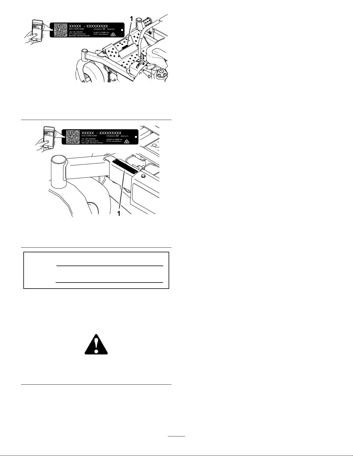
Figure1
MachineswithoutMyRide
1.Modelandserialnumberlocation
Figure2
MachineswithMyRide
ModelNo.
SerialNo.
Thismanualidentiespotentialhazardsandhas
safetymessagesidentiedbythesafety-alertsymbol
(Figure3),whichsignalsahazardthatmaycause
seriousinjuryordeathifyoudonotfollowthe
recommendedprecautions.
Figure3
Safety-alertsymbol
Thismanualuses2wordstohighlightinformation.
Importantcallsattentiontospecialmechanical
informationandNoteemphasizesgeneralinformation
worthyofspecialattention.
Contents
Safety.......................................................................4
GeneralSafety...................................................4
SlopeIndicator...................................................5
SafetyandInstructionalDecals..........................6
ProductOverview...................................................15
Controls...........................................................15
Specications..................................................17
g233854
g233855
g000502
BeforeOperation.................................................18
BeforeOperationSafety...................................18
AddingFuel......................................................18
PerformingDailyMaintenance..........................19
BreakinginaNewMachine..............................19
UsingtheRollover-ProtectionSystem
(ROPS).........................................................20
UsingtheSafety-InterlockSystem....................21
PositioningtheSeat..........................................22
ChangingtheSeatSuspension.........................22
AdjustingtheMyRide™Suspension
System..........................................................22
UsingAttachmentsandAccessories.................23
DuringOperation.................................................23
DuringOperationSafety...................................23
EnteringtheOperator’sPosition.......................25
OperatingtheParkingBrake.............................25
OperatingtheMowerBlade-ControlSwitch
(PTO)............................................................26
OperatingtheThrottle.......................................26
OperatingtheChoke........................................27
StartingtheEngine...........................................27
ShuttingOfftheEngine.....................................28
UsingtheMotion-ControlLevers.......................29
DrivingtheMachine..........................................29
AdjustingtheHeightofCut...............................31
AdjustingtheAnti-ScalpRollers........................31
AdjustingtheSideBumpers..............................32
UsingtheSideDischarge.................................33
OperatingTips.................................................33
AfterOperation....................................................34
AfterOperationSafety......................................34
UsingtheFuel-ShutoffValve.............................34
UsingtheDrive-WheelReleaseValves.............34
TransportingtheMachine.................................35
Maintenance...........................................................37
RecommendedMaintenanceSchedule(s)...........37
Pre-MaintenanceProcedures..............................38
MaintenanceSafety..........................................38
Lubrication..........................................................39
GreasingtheMachine.......................................39
LubricatingtheCaster-WheelHubs..................40
EngineMaintenance...........................................41
IdentifyingtheEngine.......................................41
EngineSafety...................................................41
ServicingaKawasaki
ServicingaKohler
®
Engine..........................41
®
Engine...............................46
ServicingaT oroEngine....................................51
CheckingtheSparkArrester.............................56
3
Page 4

ReplacingtheEmissions-AirIntake
Filter..............................................................57
FuelSystemMaintenance...................................57
ReplacingtheFuelFilter...................................57
ServicingtheFuelT ank.....................................58
ElectricalSystemMaintenance...........................58
ElectricalSystemSafety...................................58
ServicingtheBattery.........................................58
ServicingtheFuses..........................................60
DriveSystemMaintenance..................................61
CheckingtheSeatBelt.....................................61
CheckingtheRoll-BarKnobs............................61
AdjustingtheTracking......................................62
CheckingtheTirePressure...............................62
CheckingtheWheelLugNuts...........................62
CoolingSystemMaintenance..............................63
CleaningtheEngineScreen.............................63
BrakeMaintenance.............................................63
AdjustingtheParkingBrake..............................63
BeltMaintenance................................................65
InspectingtheBelts..........................................65
ReplacingtheMowerBeltforSide-Discharge
MowerDecks................................................65
ReplacingtheMowerBeltforRear-Discharge
MowerDecks................................................66
ReplacingtheHydraulicPump-Drive
Belt................................................................68
ControlsSystemMaintenance.............................69
AdjustingtheControl-HandlePosition..............69
AdjustingtheMotion-ControlLinkage...............70
HydraulicSystemMaintenance...........................71
HydraulicSystemSafety...................................71
ServicingtheHydraulicSystem........................71
MowerDeckMaintenance....................................73
ServicingtheCuttingBlades.............................73
LevelingtheMowerDeck..................................77
RemovingtheMowerDeck...............................79
ReplacingtheGrassDeector..........................79
Cleaning..............................................................80
CleaningundertheMowerDeck.......................80
CleaningtheSuspensionSystem.....................80
DisposingofWaste...........................................80
Storage...................................................................81
StorageSafety..................................................81
CleaningandStorage.......................................81
Troubleshooting......................................................82
Schematics.............................................................84
Safety
Thismachinehasbeendesignedinaccordancewith
ANSIB71.4-2012.
GeneralSafety
Thisproductiscapableofamputatinghandsand
feetandofthrowingobjects.Alwaysfollowallsafety
instructionstoavoidseriouspersonalinjury.
Usingthisproductforpurposesotherthanitsintended
usecouldprovedangeroustoyouandbystanders.
•Alwayskeeptherollbarinthefullyraisedand
lockedpositionandusetheseatbelt.
•Donotoperatethemachineneardrop-offs,
ditches,embankments,water,orotherhazards,or
onslopesgreaterthan15degrees.
•Readandunderstandthecontentsofthis
Operator’sManualbeforestartingtheengine.
•Donotputyourhandsorfeetnearmoving
componentsofthemachine.
•Donotoperatethemachinewithoutallguards
andothersafetyprotectivedevicesinplaceand
workingonthemachine.
•Keepchildrenandbystandersoutoftheoperating
area.Neverallowchildrentooperatethemachine.
•Stopthemachine,shutofftheengine,andremove
thekeybeforeservicing,fueling,orunclogging
themachine.
Improperlyusingormaintainingthismachinecan
resultininjury .Toreducethepotentialforinjury,
complywiththesesafetyinstructionsandalways
payattentiontothesafety-alertsymbol(
meansCaution,Warning,orDanger—personalsafety
instruction.Failuretocomplywiththeseinstructions
mayresultinpersonalinjuryordeath.
Youcanndadditionalsafetyinformationwhere
neededthroughoutthismanual.
),which
4
Page 5
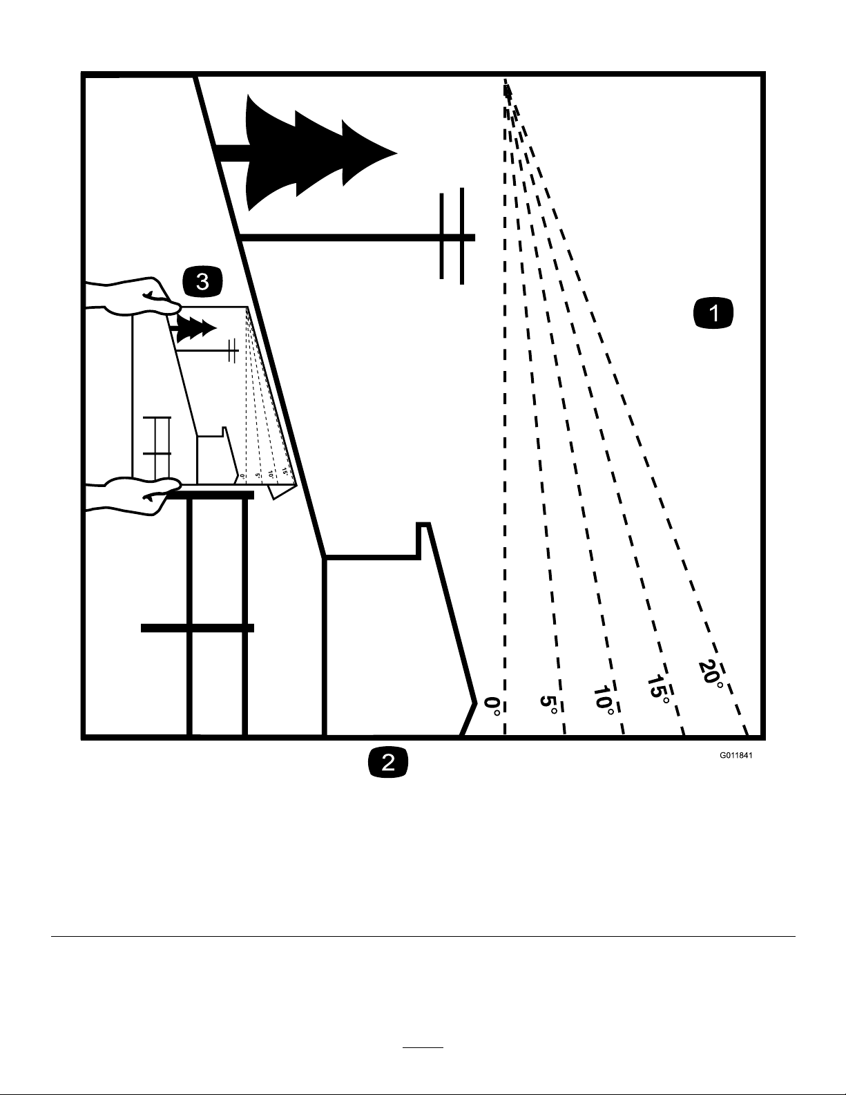
SlopeIndicator
Figure5
Youmaycopythispageforpersonaluse.
1.Themaximumslopeyoucanoperatethemachineonis15degrees.Usetheslopecharttodeterminethedegreeofslopeof
hillsbeforeoperating.Donotoperatethismachineonaslopegreaterthan15degrees.Foldalongtheappropriateline
tomatchtherecommendedslope.
2.Alignthisedgewithaverticalsurface,atree,building,fencepole,etc.
3.Exampleofhowtocompareslopewithfoldededge
5
g011841
Page 6
SafetyandInstructionalDecals
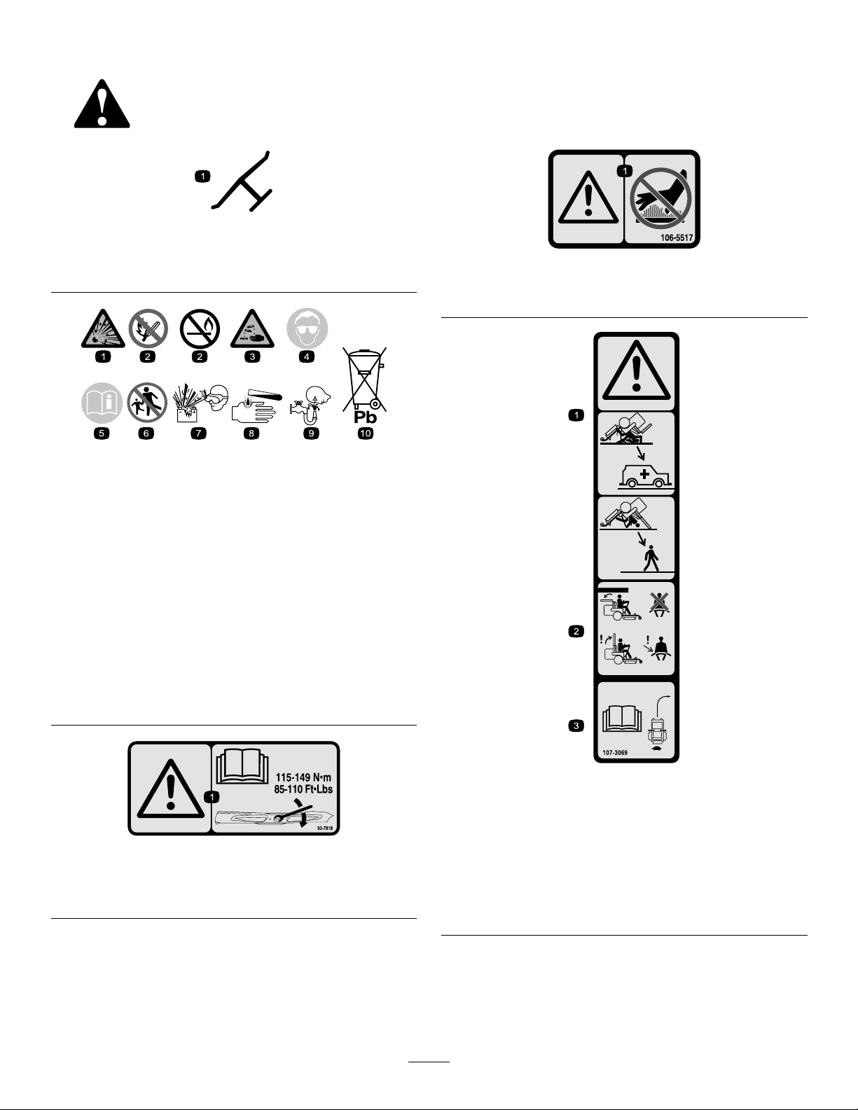
Safetydecalsandinstructionsareeasilyvisibletotheoperatorandarelocatednearanyarea
ofpotentialdanger.Replaceanydecalthatisdamagedormissing.
Manufacturer'sMark
1.Indicatesthebladeisidentiedasapartfromtheoriginal
machinemanufacturer.
BatterySymbols
Someorallofthesesymbolsareonyourbattery .
decaloemmarkt
decal106-5517
106-5517
1.Warning—donottouchthehotsurface.
decalbatterysymbols
1.Explosionhazard
2.Nore,opename,or
smoking
3.Causticliquid/chemical
burnhazard
4.Weareyeprotection.9.Flusheyesimmediately
5.ReadtheOperator's
Manual.
6.Keepbystandersasafe
distanceawayfromthe
battery.
7.Weareyeprotection;
explosivegasescan
causeblindnessandother
injuries.
8.Batteryacidcancause
blindnessorsevereburns.
withwaterandgetmedical
helpfast.
10.Containslead;donot
discard
93-7818
1.Warning—readtheOperator'sManualforinstructionson
torquingthebladebolt/nutto115-149N∙m(85-110ft-lb).
decal107-3069
107-3069
1.Warning—thereisnorolloverprotectionwhentherollbaris
down.
decal93-7818
2.Toavoidinjuryordeathfromarolloveraccident,keepthe
rollbarinthefullyraisedandlockedpositionandwear
theseatbelt.Lowertherollbaronlywhenabsolutely
necessary;donotweartheseatbeltwhentherollbaris
down.
3.ReadtheOperator'sManual;driveslowlyandcarefully.
6
Page 7
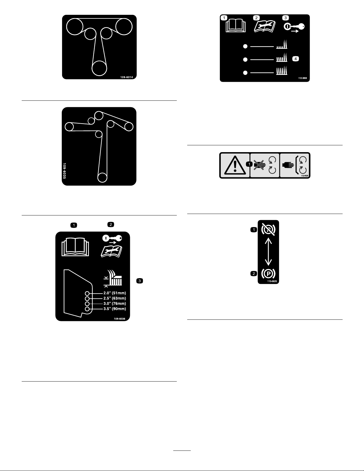
decal109-6014
109-6014
112-3858
decal112-3858
1500and2000SeriesSideDischargeMachinesOnly
109-6035
2500SeriesSideDischargeMachinesOnly
1.ReadtheOperator's
Manual.
2.Readtheinstructions
3.Removethekeybefore
adjustingtheheightofcut.
4.Height-of-cutsettings.
beforeservicingor
performingmaintenance.
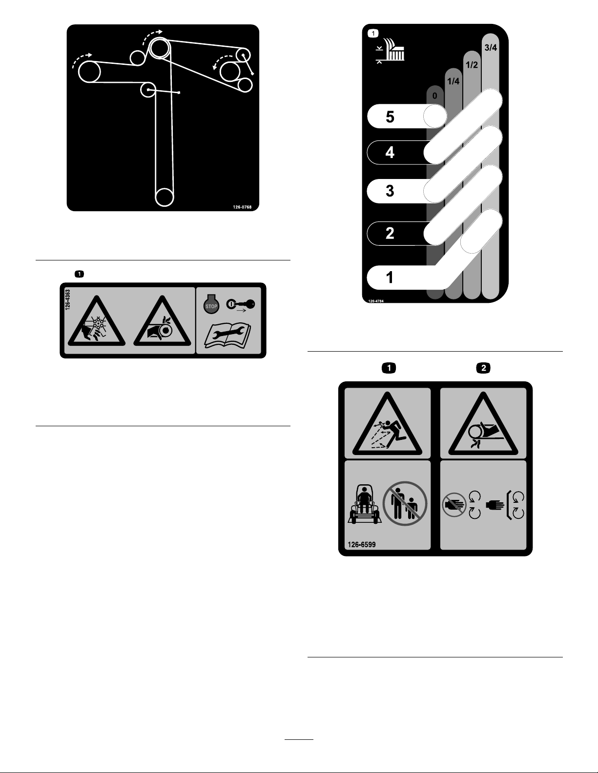
decal112-9028
decal109-6035
112-9028
1.Warning—stayawayfrommovingparts;keepallguardsin
place.
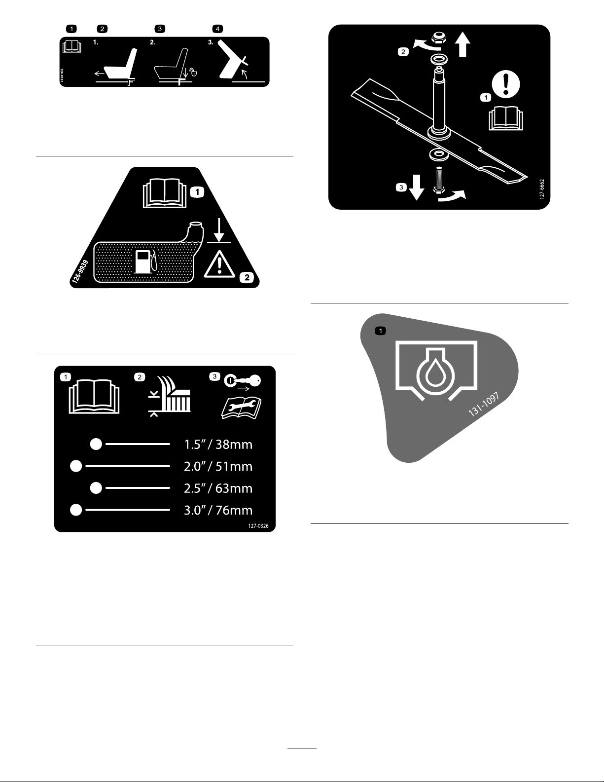
109-6036
RearDischargeMachinesOnly
1.ReadtheOperator’sManual.
2.Removethekeyandreadtheinstructionsbeforeservicing
orperformingmaintenance.
3.Heightofcut
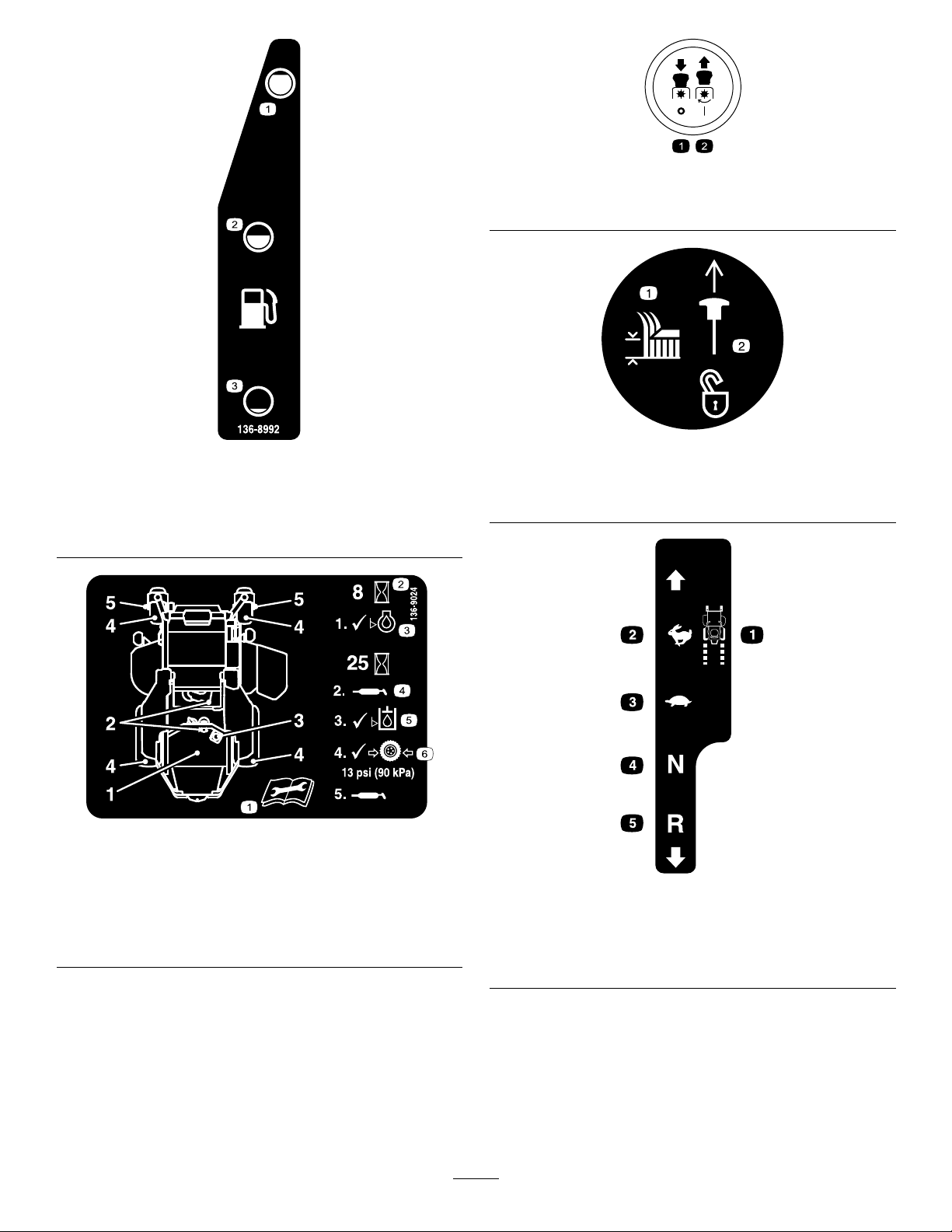
decal115-9625
115-9625
1.Parking
brake—disengaged
decal109-6036
2.Parkingbrake—engaged
7
Page 8

116-5610
1.Hourmeter4.Neutral
2.Powertakeoff(PTO)5.Operator-presenceswitch
3.Parkingbrake6.Battery
116-8588
decal116-5610
decal117-1 194
117-1194
1500and2000SeriesSide-DischargeMachinesOnly
1.Engine
decal133-8062
133-8062
decal116-8588
1.ReadtheOperator’sManual.
2.Rotatethedrivereleaseknobtoloosen,slidetheknob,
andtighten.
3.Pushthemachine.
decal117-3848
117-3848
1.Thrownobjecthazard—keepbystandersasafedistance
awayfromthemachine.
2.Thrownobjecthazard,mower—donotoperatethemachine
withoutdeector,dischargecover,orgrasscollection
systeminplace.
3.Cutting/dismembermentofhandorfoot—stayawayfrom
movingparts;keepallguardsandshieldsinplace.
8
Page 9
126-0768
RearDischargeUnitsOnly
126-4363
1.Cutting/dismembermenthazard,fanandentanglement
hazard,belt.Shutofftheengineandremovethekeybefore
adjusting,servicingorcleaningthemachine.
decal126-0768
decal126-4784
126-4784
1.Heightofcut
decal126-4363
decal126-6599
126-6599
RearDischargeUnits
1.Thrownobjects
hazard—keepbystanders
asafedistanceawayfrom
themachine.
2.Cutting/dismemberment
ofhand—stayawayfrom
movingparts;keepall
guardsandshieldsin
place.
9
Page 10
decal126-8161
126-8161
1.ReadtheOperator’s
Manual.
2.Slideseatforward
1.ReadtheOperator’s
Manual.
3.Pressdownonlatchto
unlockseat
4.Rotateseat
126-9939
2.Filltothebottomofthe
llerneck;warning—do
notoverllthetank.
decal127-6662
127-6662
RearDischargeMowersOnly
1.Attention—readthe
Operator'sManual.
2.Removethenutbyturning
decal126-9939
itclockwise.
3.Removetheboltbyturning
itcounterclockwise.
127-0326
2500SeriesSideDischargeMachinesOnly
1.ReadtheOperator's
Manual.
2.Heightofcut
decal131-1097
131-1097
ToroEnginesOnly
1.Oildrain
decal127-0326
3.Removethekeyand
readtheOperator's
Manualbeforeperforming
maintenanceorservicing
themachine.
10
Page 11
PTOSwitchSymbols
1.PTO–disengage2.PTO–engage
decalptosymbols
136-8992
MachineswithMyRideOnly
1.Fuel—full
2.Fuel—50%
3.Fuel—empty
136-9024
1.ReadtheOperator’s
Manualbeforeperforming
maintenance.
2.Operatinghours5.Hydraulic-uidlevel
3.Engine-oillevel6.Tirepressure
4.Greasepoint
decal136-8992
1.Heightofcut
TransportLock
2.Pulluptounlockthe
decaltransportlock
transportlock.
decal136-9024
decalmotioncntrllh-126-6194
LeftMotionControl
1.Machinespeed4.Neutral
2.Fast5.Reverse
3.Slow
11
Page 12
RightMotionControl
1.Machinespeed4.Neutral
2.Fast5.Reverse
3.Slow
decalmotioncntrlrh-126-6183
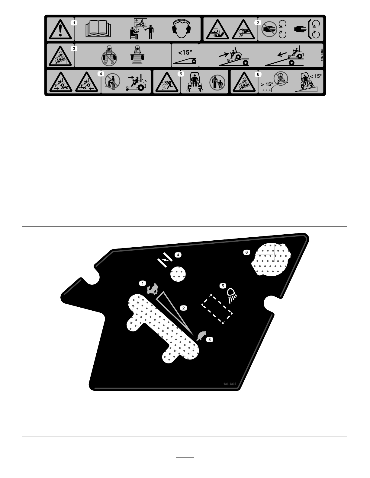
decal126-8151
126-8151
1.Readtheinstructionsbeforeservicingorperforming
4.RefertotheOperator'sManualforgreaseinstructions.
maintenanceonthemachine.
2.Timeinterval
5.Checkthehydraulic-uidlevelandrefertotheOperator's
Manualforfurtherinstructions.
3.Checktheoillevel.6.Checkthetirepressure.
12
Page 13
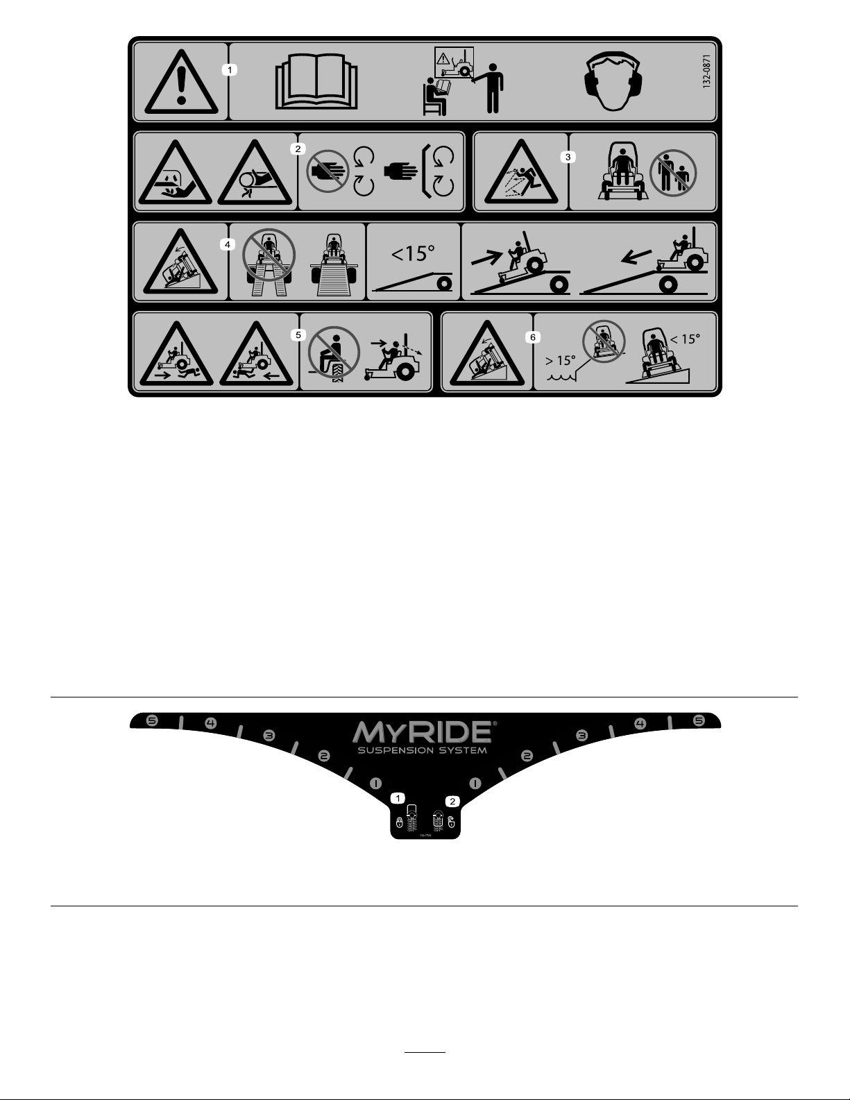
126-8383
MachineswithoutMyRideOnly
Note:Thismachinecomplieswiththeindustrystandardstabilitytestinthestaticlateralandlongitudinaltestswiththemaximum
recommendedslopeindicatedonthedecal.ReviewtheinstructionsforoperatingthemachineonslopesintheOperator’sManualas
wellastheconditionsinwhichyouwouldoperatethemachinetodeterminewhetheryoucanoperatethemachineinthoseconditions
onthatdayandatthatsite.Changesintheterraincanresultinachangeinslopeoperationforthemachine.Ifpossible,keepthe
cuttingunitsloweredtothegroundwhileoperatingthemachineonslopes.Raisingthecuttingunitswhileoperatingonslopescan
causethemachinetobecomeunstable.
decal126-8383
1.Warning—readtheOperator’sManual;donotoperatethis
machineunlessyouaretrained;wearhearingprotection.
2.Cutting,dismembering,andentanglementhazard—keep
handsawayfrommovingparts;keepallguardsandshieldsin
place.
3.Ramphazard—whenloadingontoatrailer,donotusedual
ramps;onlyuseasingularrampwideenoughforthemachine
andthathasaninclinelessthan15°;backuptheramp(in
reverse)anddriveforwardofftheramp.
4.Bodilyharmhazard—donotcarrypassengers;lookbehind
youwhenmowinginreverse.
5.Thrownobjecthazard—keepbystandersaway.
6.Tippinghazardonslopes—donotuseonslopesnearopen
water;donotuseonslopesgreaterthan15°.
136-1305
1.Fast
2.Continuous-variablesetting5.Worklight(optional)
3.Slow
4.Choke
6.Powerpoint
13
decal136-1305
Page 14
132-0871
MachineswithMyRideOnly
Note:Thismachinecomplieswiththeindustrystandardstabilitytestinthestaticlateralandlongitudinaltestswiththemaximum
recommendedslopeindicatedonthedecal.ReviewtheinstructionsforoperatingthemachineonslopesintheOperator’sManualas
wellastheconditionsinwhichyouwouldoperatethemachinetodeterminewhetheryoucanoperatethemachineinthoseconditions
onthatdayandatthatsite.Changesintheterraincanresultinachangeinslopeoperationforthemachine.Ifpossible,keepthe
cuttingunitsloweredtothegroundwhileoperatingthemachineonslopes.Raisingthecuttingunitswhileoperatingonslopescan
causethemachinetobecomeunstable.
decal132-0871
1.Warning—readtheOperator’sManual;donotoperatethis
machineunlessyouaretrained;wearhearingprotection.
4.Ramphazard—whenloadingontoatrailer,donotusedual
ramps;onlyuseasingularrampwideenoughforthemachine
andthathasaninclinelessthan15°;backuptheramp(in
reverse)anddriveforwardofftheramp.
2.Cutting,dismembering,andentanglementhazard—keep
handsawayfrommovingparts;keepallguardsandshieldsin
5.Bodilyharmhazard—donotcarrypassengers;lookbehind
youwhenmowinginreverse.
place.
3.Thrownobjecthazard—keepbystandersaway.6.Tippinghazardonslopes—donotuseonslopesnearopen
water;donotuseonslopesgreaterthan15°.
136-1720
1.Camlock2.Camunlock
decal136-1720
14
Page 15
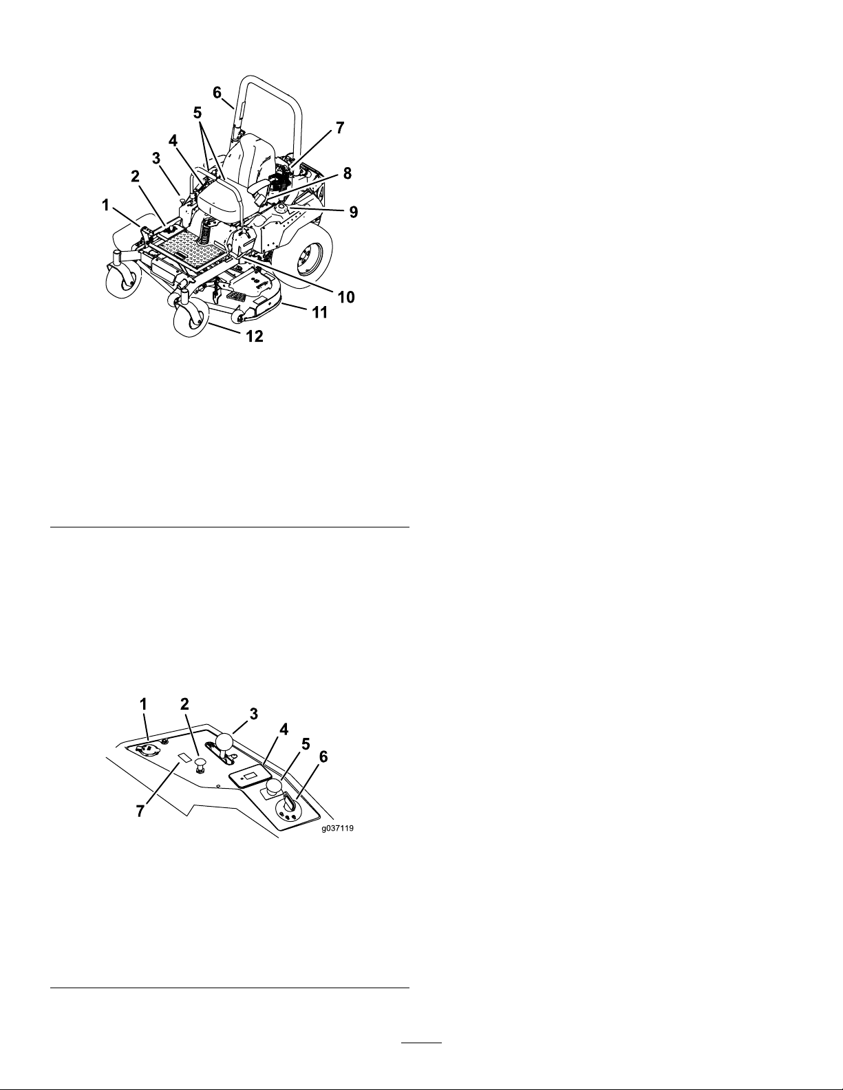
ProductOverview
KeySwitch
Thekeyswitch,usedtostartandshutofftheengine,
has3positions:OFF,RUN,andST ART.Referto
StartingtheEngine(page27).
ChokeControl
Usethechokecontroltostartacoldengine.
ThrottleControl
Thethrottlecontrolstheenginespeed,andithasa
continuous-variablesettingfromtheSLOWtoFAST
position(Figure7).
Figure6
1.Height-of-cutdeck-lift
pedal
2.Height-of-cutpositions8.Seatbelt
3.Transportlock9.Fuelcap
4.Controls
5.Motion-controllevers11.Mowerdeck
6.Rollbar
7.Shockassembly
(machineswithMyRide
only)
10.Parking-brakelever
12.Casterwheel
Controls
Becomefamiliarwithallthecontrolsbeforeyoustart
theengineandoperatethemachine(Figure6and
Figure7).
ControlPanel
g227688
Blade-ControlSwitch(Power
Takeoff)
Theblade-controlswitch,representedbya
power-takeoff(PTO)symbol,engagesand
disengagespowertothemowerblades(Figure7).
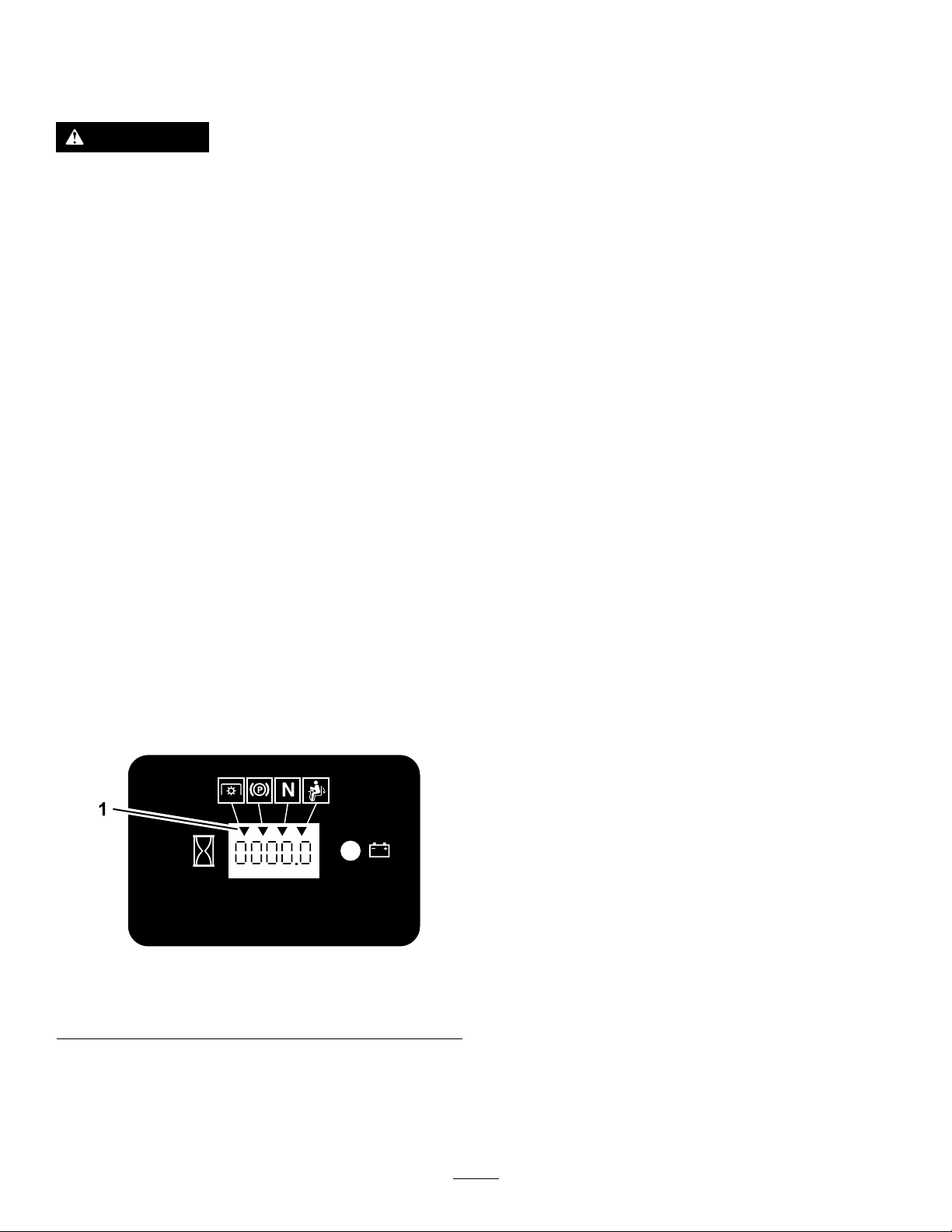
HourMeter
Thehourmeterrecordsthenumberofhoursthe
enginehasoperated.Itoperateswhentheengine
isrunning.Usethesetimesforschedulingregular
maintenance(Figure8).
Safety-InterlockIndicators
Therearesymbolsonthehourmeterthatindicate
withablacktrianglethattheinterlockcomponentis
positionedcorrectly(Figure8).
Figure7
1.Powerport5.Blade-controlswitch
2.Chokecontrol
3.Throttlecontrol
4.Hourmeter
(powertakeoff)
6.Keyswitch
7.Switchpositionforoptional
lightkit
g037119
15
Page 16
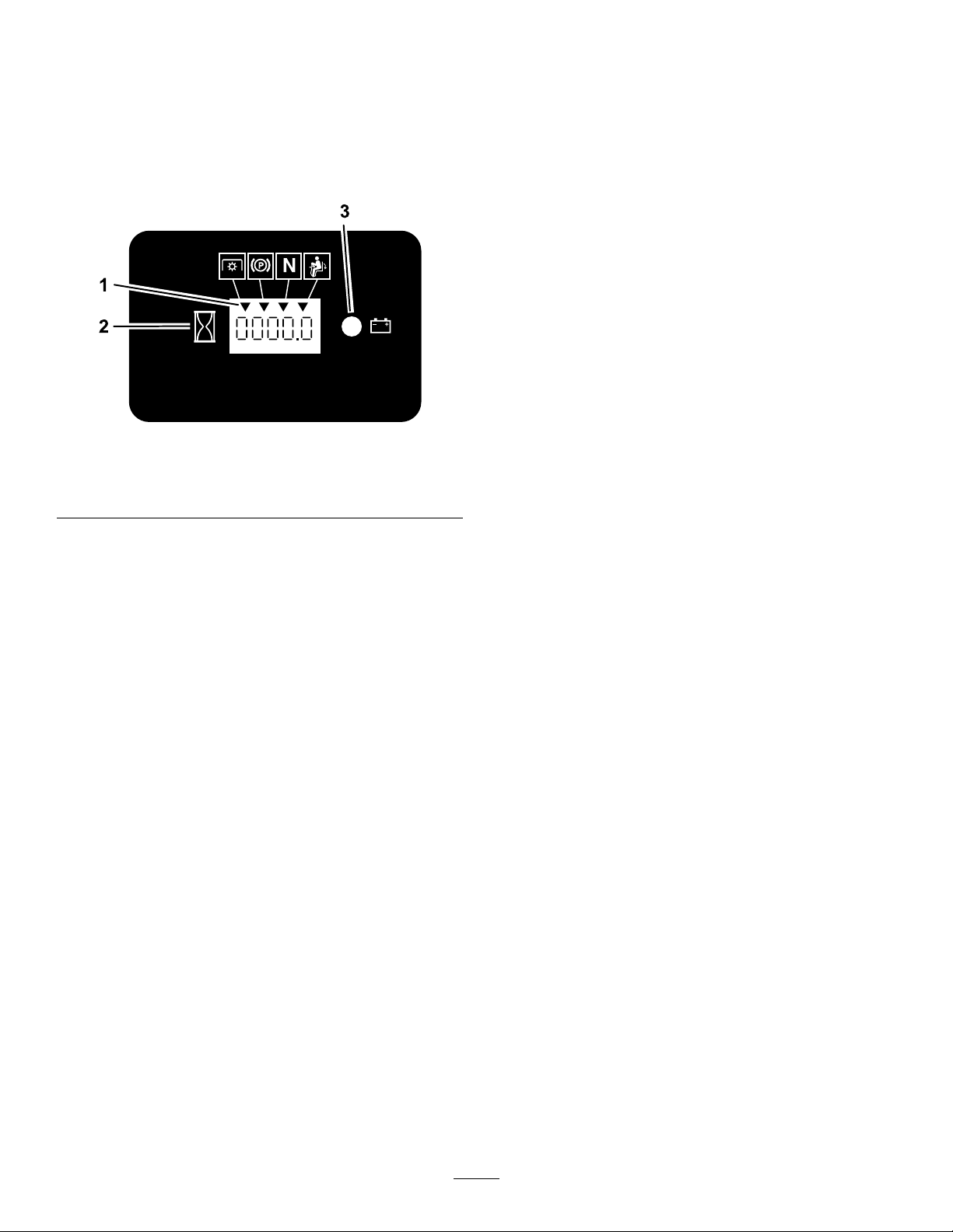
Battery-IndicatorLight
IfyouturntheignitionkeytotheONpositionfora
fewseconds,thebatteryvoltagedisplaysinthearea
wherethehoursarenormallydisplayed.
Thebatterylightturnsonwhentheignitionisturned
onandwhenthechargeisbelowthecorrectoperating
level(Figure8).
Figure8
g187133
1.Safety-interlocksymbols
2.Hourmeter
3.Batterylight
Motion-ControlLevers
Usethemotion-controlleverstodrivethemachine
forward,reverse,andturneitherdirection(Figure7).
Neutral-LockPosition
UsetheNEUTRAL-LOCKpositionwiththe
safety-interlocksystemtoengageandtodetermine
theNEUTRALposition.
Fuel-ShutoffValve
Closethefuel-shutoffvalvewhentransportingor
storingthemachine;refertoUsingtheFuel-Shutoff
Valve(page34).
Attachments/Accessories
AselectionofT oroapprovedattachmentsand
accessoriesisavailableforusewiththemachine
toenhanceandexpanditscapabilities.Contact
yourAuthorizedServiceDealerorauthorizedT oro
distributororgotowww.Toro.comforalistofall
approvedattachmentsandaccessories.
Toensureoptimumperformanceandcontinuedsafety
certicationofthemachine,useonlygenuineT oro
replacementpartsandaccessories.Replacement
partsandaccessoriesmadebyothermanufacturers
couldbedangerous,andsuchusecouldvoidthe
productwarranty.
16
Page 17

Specications
Note:Specicationsanddesignaresubjecttochangewithoutnotice.
Width—MachineswithSideDischargeMowerDecks
48-inchDeck52-inchDeck60-inchDeck
Withoutmowerdeck
Deectorup133cm(53inches)144cm(56-3/4inches)161cm(63-1/2inches)
Deectordown160cm(63-1/4inches)171cm(67-1/4inches)191cm(75-1/4inches)
Width—MachineswithRearDischargeMowerDecks
Withoutmowerdeck
Withmowerdeck
Length—MachineswithSideDischargeMowerDecks
Length
Length—MachineswithRearDischargeMowerDecks
121cm(47-1/2inches)124cm(49inches)133cm(52inches)
60-inchDeck
133cm(52inches)
168cm(66inches)
48-inchDeck52-inchDeck60-inchDeck
208cm(82inches)208cm(82inches)209cm(83inches)
60-inchDeck
Withmowerdeck
215cm(84-1/2inches)
Height
RollBar-UpRollBar-Down
179cm(70-1/2inches)49inches(125cm)
Weight
MachinesWeight
48-inchside-dischargemachines
52-inchside-dischargemachines
60-inchside-dischargemachines
60-inchrear-dischargemachines
385to425kg(849to937lb)
391to434kg(862to957lb)
409to456kg(901to1006lb)
459kg(1,012lb)
17
Page 18

Operation
Note:Determinetheleftandrightsidesofthe
machinefromthenormaloperatingposition.
BeforeOperation
BeforeOperationSafety
GeneralSafety
•Neverallowchildrenoruntrainedpeopleto
operateorservicethemachine.Localregulations
mayrestricttheageoftheoperator.Theowner
isresponsiblefortrainingalloperatorsand
mechanics.
•Becomefamiliarwiththesafeoperationofthe
equipment,operatorcontrols,andsafetysigns.
•Knowhowtostopthemachineandshutoffthe
enginequickly.
•Checkthatoperator-presencecontrols,safety
switches,andshieldsareattachedandfunctioning
properly.Donotoperatethemachineunlessthey
arefunctioningproperly.
•Beforemowing,alwaysinspectthemachineto
ensurethattheblades,bladebolts,andcutting
assembliesareingoodworkingcondition.
Replacewornordamagedbladesandboltsinsets
topreservebalance.
•Inspecttheareawhereyouwillusethemachine
andremoveallobjectsthatthemachinecould
throw.
•Evaluatetheterraintodeterminetheappropriate
equipmentandanyattachmentsoraccessories
requiredtooperatethemachineproperlyand
safely.
FuelSafety
•Toavoidpersonalinjuryorpropertydamage,use
extremecareinhandlingfuel.Fuelvaporsare
ammableandexplosive.
•Extinguishallcigarettes,cigars,pipes,andother
sourcesofignition.
•Useonlyanapprovedfuelcontainer.
•Donotremovethefuelcaporaddfueltothefuel
tankwhiletheengineisrunningorwhilehot.
•Donotrefuelthemachineindoors.
•Donotstorethemachineorfuelcontainerwhere
thereisanopename,spark,orpilotlight,such
asonawaterheateroronotherappliances.
•Donotllcontainersinsideavehicleoronatruck
ortrailerbedwithaplasticliner.Alwaysplace
containersontheground,awayfromyourvehicle
beforelling.
•Removetheequipmentfromthetruckortrailer
andrefuelitwhileitisontheground.Ifthisisnot
possible,thenrefuelfromaportablecontainer
ratherthanafuel-dispensernozzle.
•Donotoperatethemachinewithouttheentire
exhaustsysteminplaceandinproperworking
condition.
•Keepthefuel-dispensernozzleincontactwith
therimofthefueltankorcontaineropeningat
alltimesuntilfuelingiscomplete.Donotusea
nozzlelock-opendevice.
•Ifyouspillfuelonyourclothing,changeyour
clothingimmediately.Wipeupanyfuelthatspills.
•Neveroverllthefueltank.Replacethefuelcap
andtightenitsecurely.
•Storefuelinanapprovedcontainerandkeepit
outofthereachofchildren.Neverbuymorethan
a30-daysupplyoffuel.
•Donotllthefueltankcompletelyfull.Addfuelto
thefueltankuntilthelevelis6to13mm(1/4to
1/2inch)belowthebottomofthellerneck.This
emptyspaceinthetankallowsfueltoexpand.
–Avoidprolongedbreathingofvapors.
–Keepyourfaceawayfromthenozzleandfuel
tankopening.
–Avoidcontactwithskin;washoffspillswith
soapandwater.
AddingFuel
RecommendedFuel
•Forbestresults,useonlyclean,fresh(lessthan
30daysold),unleadedgasolinewithanoctane
ratingof87orhigher((R+M)/2ratingmethod).
•Ethanol:Gasolinewithupto10%ethanol
(gasohol)or15%MTBE(methyltertiarybutyl
ether)byvolumeisacceptable.Ethanoland
MTBEarenotthesame.Gasolinewith15%
ethanol(E15)byvolumeisnotapprovedforuse.
Neverusegasolinethatcontainsmorethan
10%ethanolbyvolume,suchasE15(contains
15%ethanol),E20(contains20%ethanol),orE85
(containsupto85%ethanol).Usingunapproved
gasolinemaycauseperformanceproblemsand/or
enginedamagewhichmaynotbecoveredunder
warranty.
•Donotusegasolinecontainingmethanol.
•Donotstorefueleitherinthefueltankorfuel
containersoverthewinterunlessyouuseafuel
stabilizer.
•Donotaddoiltogasoline.
18
Page 19
UsingStabilizer/Conditioner
Useafuelstabilizer/conditionerinthemachineto
providethefollowingbenets:
•Keepsfuelfreshlongerwhenusedasdirectedby
thefuel-stabilizermanufacturer
•Cleanstheenginewhileitruns
•Eliminatesgum-likevarnishbuildupinthefuel
system,whichcauseshardstarting
Important:Donotusefueladditives
containingmethanolorethanol.
Addthecorrectamountoffuelstabilizer/conditioner
tothefuel.
Note:Afuelstabilizer/conditionerismost
effectivewhenmixedwithfreshfuel.T ominimize
thechanceofvarnishdepositsinthefuelsystem,
usefuelstabilizeratalltimes.
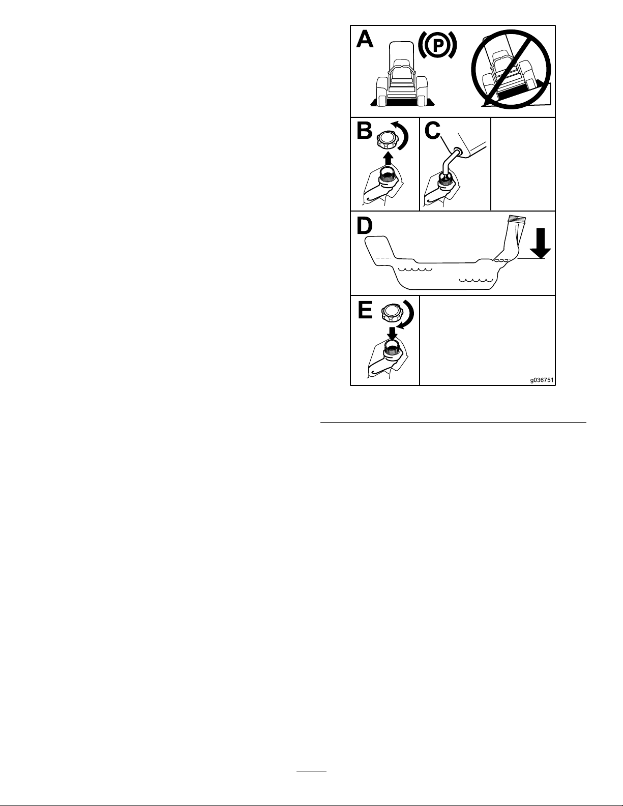
FillingtheFuelTank
1.Parkthemachineonalevelsurface.
2.Engagetheparkingbrake.
3.Shutofftheengineandremovethekey.
4.Cleanaroundthefuel-tankcap.
5.Fillthefueltanktothebottomofthellerneck
(Figure9).
Note:Donotllthefueltankcompletelyfull.
Theemptyspaceinthetankallowsthefuelto
expand.
g036751
Figure9
PerformingDaily Maintenance
Beforestartingthemachineeachday ,performthe
EachUse/DailyprocedureslistedinMaintenance
(page37).
BreakinginaNewMachine
Newenginestaketimetodevelopfullpower.Mower
decksanddrivesystemshavehigherfrictionwhen
new,placingadditionalloadontheengine.Allow
40to50hoursofbreak-intimefornewmachinesto
developfullpowerandbestperformance.
19
Page 20
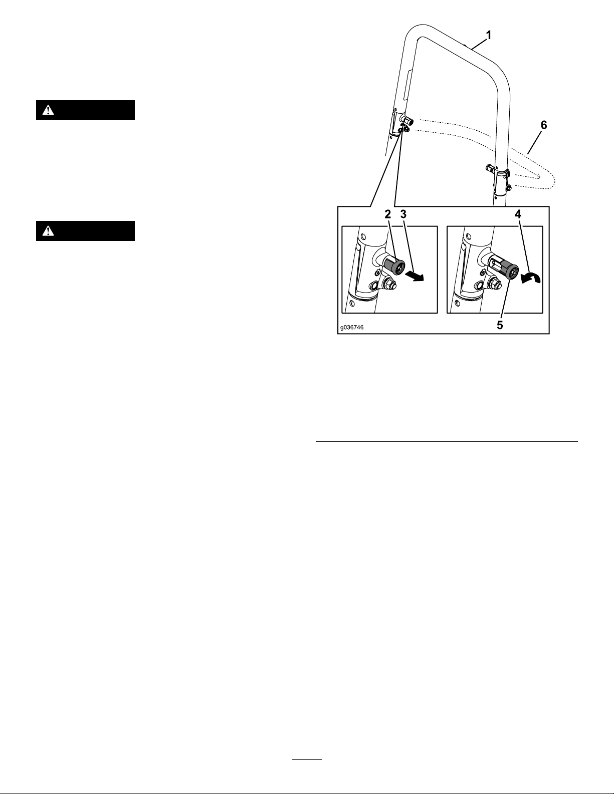
Usingthe Rollover-ProtectionSystem (ROPS)
WARNING
Toavoidinjuryordeathfromrollover,keep
therollbarinthefullyraised,lockedposition
andusetheseatbelt.
Ensurethattheseatissecuredtothe
machine.
WARNING
Thereisnorolloverprotectionwhentheroll
barisinthedownposition.
•Lowertherollbaronlywhenabsolutely
necessary.
•Donotweartheseatbeltwhentherollbar
isinthedownposition.
•Driveslowlyandcarefully.
g036746
Figure10
•Raisetherollbarassoonasclearance
permits.
•Checkcarefullyforoverheadclearances
(i.e.,branches,doorways,electricalwires)
beforedrivingunderanyobjectsanddo
notcontactthem.
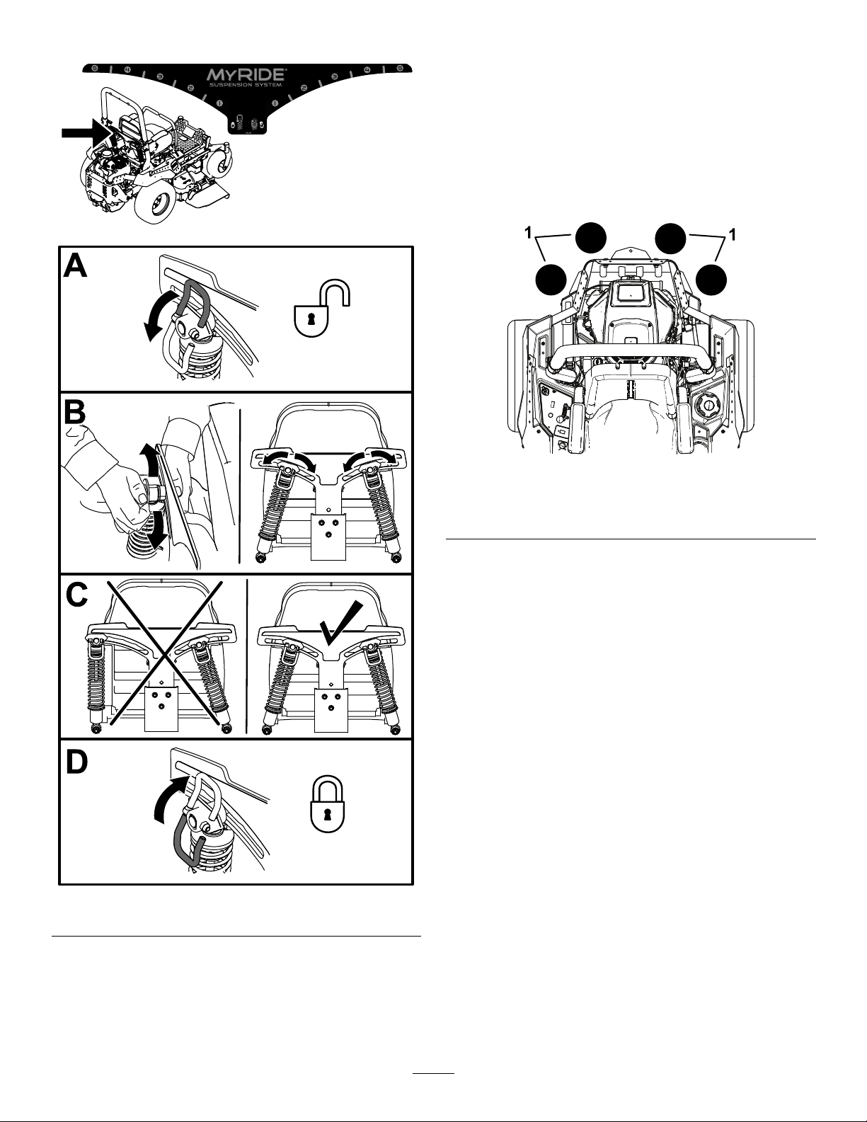
LoweringtheRollBar
Important:Lowertherollbaronlywhen
absolutelynecessary.
1.T olowertherollbar,applyforwardpressureto
theupperpartoftherollbar.
2.Pullbothknobsoutandrotatethem90degrees
sothattheyarenotengaged(Figure10).
3.Lowertherollbartothedownposition(Figure
10).
1.Rollbarintheupright
position
2.ROPSknobinthelatched
position
3.PulltheROPSknobout.6.Rollbarinthefolded
4.RotatetheROPSknob90
degrees.
5.ROPSknobinthe
unlatchedposition
position
RaisingtheRollBar
Important:Alwaysusetheseatbeltwiththeroll
barintheraisedposition.
1.Raisetherollbartotheoperatingpositionand
rotatetheknobsuntiltheymovepartiallyinto
thegrooves(Figure10).
2.Raisetherollbartothefulluprightpositionwhile
pushingontheupperrollbarsothatthepins
snapintopositionwhentheholesalignwiththe
pins(Figure10).
3.Pushontherollbarandensurethatbothpins
areengaged.
20
Page 21
UsingtheSafety-Interlock System
TestingtheSafety-Interlock System
ServiceInterval:Beforeeachuseordaily
WARNING
Ifthesafety-interlockswitchesare
disconnectedordamaged,themachinecould
operateunexpectedly,causingpersonal
injury.
•Donottamperwiththeinterlockswitches.
•Checktheoperationoftheinterlock
switchesdailyandreplaceanydamaged
switchesbeforeoperatingthemachine.
Understandingthe Safety-InterlockSystem
Thesafety-interlocksystemisdesignedtopreventthe
enginefromstartingunless:
•Theblade-controlswitch(PTO)isdisengaged.
•Themotion-controlleversareintheNEUTRAL-LOCK
position.
•Theparkingbrakeisengaged.
Thesafety-interlocksystemisalsodesignedtoshutoff
theenginewhenthetractioncontrolsaremovedfrom
thelockedpositionwiththeparkingbrakeengagedor
ifyourisefromtheseatwhenthePTOisengaged.
Thehourmeterhassymbolstonotifytheuserwhen
theinterlockcomponentisinthecorrectposition.
Whenthecomponentisinthecorrectposition,a
trianglelightsupinthecorrespondingsquare.
Testthesafety-interlocksystembeforeyouusethe
machineeachtime.Ifthesafetysystemdoesnot
operateasdescribedbelow,haveanAuthorized
ServiceDealerrepairthesafetysystemimmediately .
1.Sitontheseat,engagetheparkingbrake,and
movetheblade-controlswitch(PTO)totheON
position.Trystartingtheengine;theengine
shouldnotcrank.
2.Sitontheseat,engagetheparkingbrake,and
movetheblade-controlswitch(PTO)totheOFF
position.Moveeithermotion-controllever(out
oftheNEUTRAL-LOCKposition).Trystartingthe
engine;theengineshouldnotcrank.Repeatfor
othercontrollever.
3.Sitontheseat,engagetheparkingbrake,
movetheblade-controlswitch(PTO)totheOFF
position,andmovethemotion-controlleversto
theNEUTRAL-LOCKposition.Starttheengine.
Whiletheengineisrunning,disengagethe
parkingbrake,engagetheblade-controlswitch
(PTO),andriseslightlyfromtheseat;theengine
shouldshutoff.
4.Sitontheseat,engagetheparkingbrake,
movetheblade-controlswitch(PTO)totheOFF
position,andmovethemotion-controllevers
toNEUTRAL-LOCKposition.Starttheengine.
Whiletheengineisrunning,centereither
motion-controlleverandmoveitforwardor
reverse;theengineshouldshutoff.Repeatfor
othermotion-controllever.
5.Sitontheseat,disengagetheparkingbrake,
movetheblade-controlswitch(PTO)totheOFF
position,andmovethemotion-controlleversto
NEUTRAL-LOCKposition.Trystartingtheengine;
theengineshouldnotcrank.
Figure11
1.Triangleslightupwhentheinterlockcomponentsareinthe
correctposition
g187670
21
Page 22
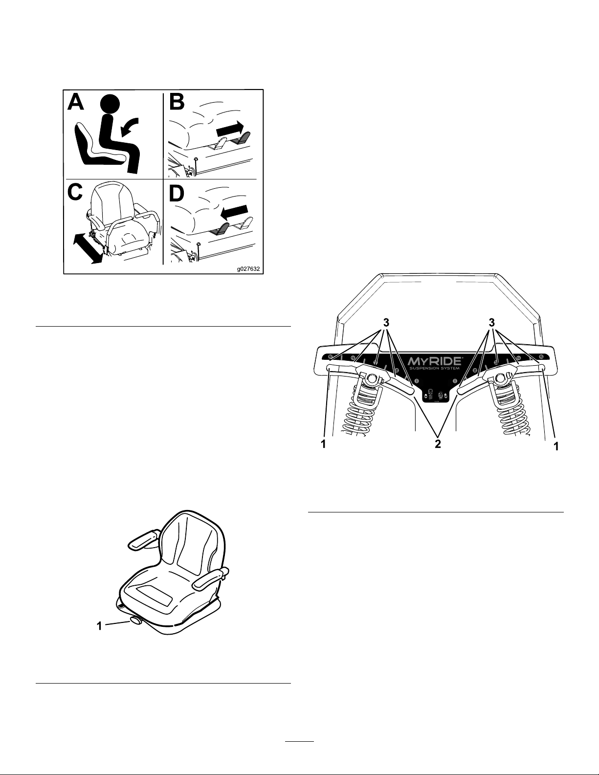
PositioningtheSeat
AdjustingtheMyRide™
Theseatcanmoveforwardandbackward(Figure12).
Positiontheseatwhereyouhavethebestcontrolof
themachineandaremostcomfortable.
Figure12
SeatformachineswithMyRideshown.
SuspensionSystem
TheMyRide™suspensionsystemadjuststoprovide
asmoothandcomfortableride.Youcanadjustthe
rear2-shockassembliestoquicklyandeasilychange
thesuspensionsystem.Positionthesuspension
systemwhereyouaremostcomfortable.
AdjustingtheRear-Shock Assemblies
Theslotsfortherear-shockassemblieshave
detentpositionsforreference.Youcanpositionthe
rear-shockassembliesanywhereintheslot,notjust
inthedetentpositions.
Thefollowinggraphicshowsthepositionforasoftor
rmrideandthedifferentdetentpositions(Figure14).
g027632
ChangingtheSeat Suspension
MachineswithoutMyRide™
SuspensionSystemOnly
Theseatisadjustabletoprovideasmoothand
comfortableride.Positiontheseatwhereyouare
mostcomfortable.
Toadjustit,turntheknobinfronteitherdirectionto
providethebestcomfort(Figure13).
Figure13
g227753
Figure14
1.Firmestposition3.Detentsintheslots
2.Softestposition
Note:Ensurethattheleftandrightrear-shock
assembliesarealwaysadjustedtothesamepositions.
g024881
1.Seat-suspensionknob
22
Page 23
Adjusttherear-shockassemblies(Figure15).
UsingAttachmentsand Accessories
UseonlyToroapprovedattachmentsandaccessories.
Ifmorethanoneaccessory-mountkit(i.e.,bucket
kitoruniversalmountkit)isaddedtoanyofthe4
locationsshowninFigure16,addafront-weight
kit.ContactyourAuthorizedServiceDealerforthe
front-weightkit.
g227752
Figure15
g037417
Figure16
1.Addafront-weightkitwhen2ormoreaccessory-mountkits
areinstalledatthesepositions.
DuringOperation
DuringOperationSafety
GeneralSafety
•Theowner/operatorcanpreventandisresponsible
foraccidentsthatmaycausepersonalinjuryor
propertydamage.
•Wearappropriateclothing,includingeye
protection;longpants;slip-resistant,substantial
footwear;andhearingprotection.Tiebacklong
hairanddonotwearloosejewelry .
•Useyourfullattentionwhileoperatingthe
machine.Donotengageinanyactivitythat
g227751
causesdistractions;otherwise,injuryorproperty
damagemayoccur.
•Donotoperatethemachinewhileill,tired,or
undertheinuenceofalcoholordrugs.
•Nevercarrypassengersonthemachineandkeep
bystandersandpetsawayfromthemachine
duringoperation.
•Operatethemachineonlyingoodvisibilitytoavoid
holesorhiddenhazards.
23
Page 24

•Avoidmowingonwetgrass.Reducedtraction
couldcausethemachinetoslide.
•Ensurethatalldrivesareinneutral,theparking
brakeisengaged,andyouareintheoperating
positionbeforeyoustarttheengine.
•Keepyourhandsandfeetawayfromthecutting
units.Keepclearofthedischargeopeningatall
times.
•Lookbehindanddownbeforebackinguptobe
sureofaclearpath.
•Usecarewhenapproachingblindcorners,shrubs,
trees,orotherobjectsthatmayobscureyour
vision.
•Donotmowneardrop-offs,ditches,or
embankments.Themachinecouldsuddenlyroll
overifawheelgoesovertheedgeoriftheedge
givesway.
•Stopthebladeswheneveryouarenotmowing.
•Stopthemachine,shutofftheengine,remove
thekey,andinspectthebladesafterstrikingan
objectorifthereisanabnormalvibrationinthe
machine.Makeallnecessaryrepairsbefore
resumingoperation.
•Slowdownandusecautionwhenmakingturns
andcrossingroadsandsidewalkswiththe
machine.Alwaysyieldtheright-of-way.
•Disengagethedrivetothecuttingunit,shutoffthe
engine,andremovethekeybeforeadjustingthe
heightofcut(unlessyoucanadjustitfromthe
operatingposition).
•Neverrunanengineinanareawhereexhaust
gasesareenclosed.
•Neverleavearunningmachineunattended.
•Beforeleavingtheoperatingposition(including
toemptythecatchersortounclogthechute),do
thefollowing:
–Stopthemachineonlevelground.
–Disengagethepowertakeoffandlowerthe
attachments.
–Engagetheparkingbrake.
–Shutofftheengineandremovethekey.
–Waitforallmovingpartstostop.
•Donotoperatethemachinewhenthereistherisk
oflightning.
•Donotusethemachineasatowingvehicleunless
ithasahitchinstalled.
•Donotchangethegovernorspeedoroverspeed
theengine.
•Useonlyaccessoriesandattachmentsapproved
byToro.
•Thismachineproducessoundlevelsinexcess
of85dBAattheoperator’searandcancause
hearinglossthroughextendedperiodsof
exposure.
g229846
Figure17
1.Wearhearingprotection.
RolloverProtectionSystem (ROPS)Safety
•Donotremovetherollbarfromthemachine.
•Ensurethattheseatbeltisattachedandthatyou
canreleaseitquicklyinanemergency.
•Alwayswearyourseatbeltwhentherollbarisup.
•Checkcarefullyforoverheadobstructionsanddo
notcontactthem.
•Keeptherollbarinsafeoperatingconditionby
thoroughlyinspectingitperiodicallyfordamage
andkeepingallthemountingfastenerstight.
•Replaceadamagedrollbar.Donotrepairoralter
it.
SlopeSafety
•Slopesareamajorfactorrelatedtolossofcontrol
androlloveraccidents,whichcanresultinsevere
injuryordeath.Theoperatorisresponsiblefor
safeslopeoperation.Operatingthemachineon
anysloperequiresextracaution.Beforeusingthe
machineonaslope,dothefollowing:
–Reviewandunderstandtheslopeinstructions
inthemanualandonthemachine.
–Useanangleindicatortodeterminethe
approximateslopeangleofthearea.
–Neveroperateonslopesgreaterthan15
degrees.
–Evaluatethesiteconditionsofthedayto
determineiftheslopeissafeformachine
operation.Usecommonsenseandgood
judgmentwhenperformingthisevaluation.
Changesintheterrain,suchasmoisture,can
quicklyaffecttheoperationofthemachineon
aslope.
•Identifyhazardsatthebaseoftheslope.Do
notoperatethemachineneardrop-offs,ditches,
embankments,water,orotherhazards.The
machinecouldsuddenlyrolloverifawheelgoes
overtheedgeortheedgecollapses.Keepasafe
distance(twicethewidthofthemachine)between
24
Page 25
themachineandanyhazard.Useawalk-behind
machineorahandtrimmertomowthegrassin
theseareas.
•Avoidstarting,stopping,orturningthemachineon
slopes.Avoidmakingsuddenchangesinspeedor
direction;turnslowlyandgradually.
•Donotoperateamachineunderanyconditions
wheretraction,steering,orstabilityisinquestion.
Beawarethatoperatingthemachineonwet
grass,acrossslopes,ordownhillmaycausethe
machinetolosetraction.Lossoftractiontothe
drivewheelsmayresultinslidingandalossof
brakingandsteering.Themachinecanslideeven
ifthedrivewheelsarestopped.
•Removeormarkobstaclessuchasditches,holes,
ruts,bumps,rocks,orotherhiddenhazards.T all
grasscanhideobstacles.Uneventerraincould
overturnthemachine.
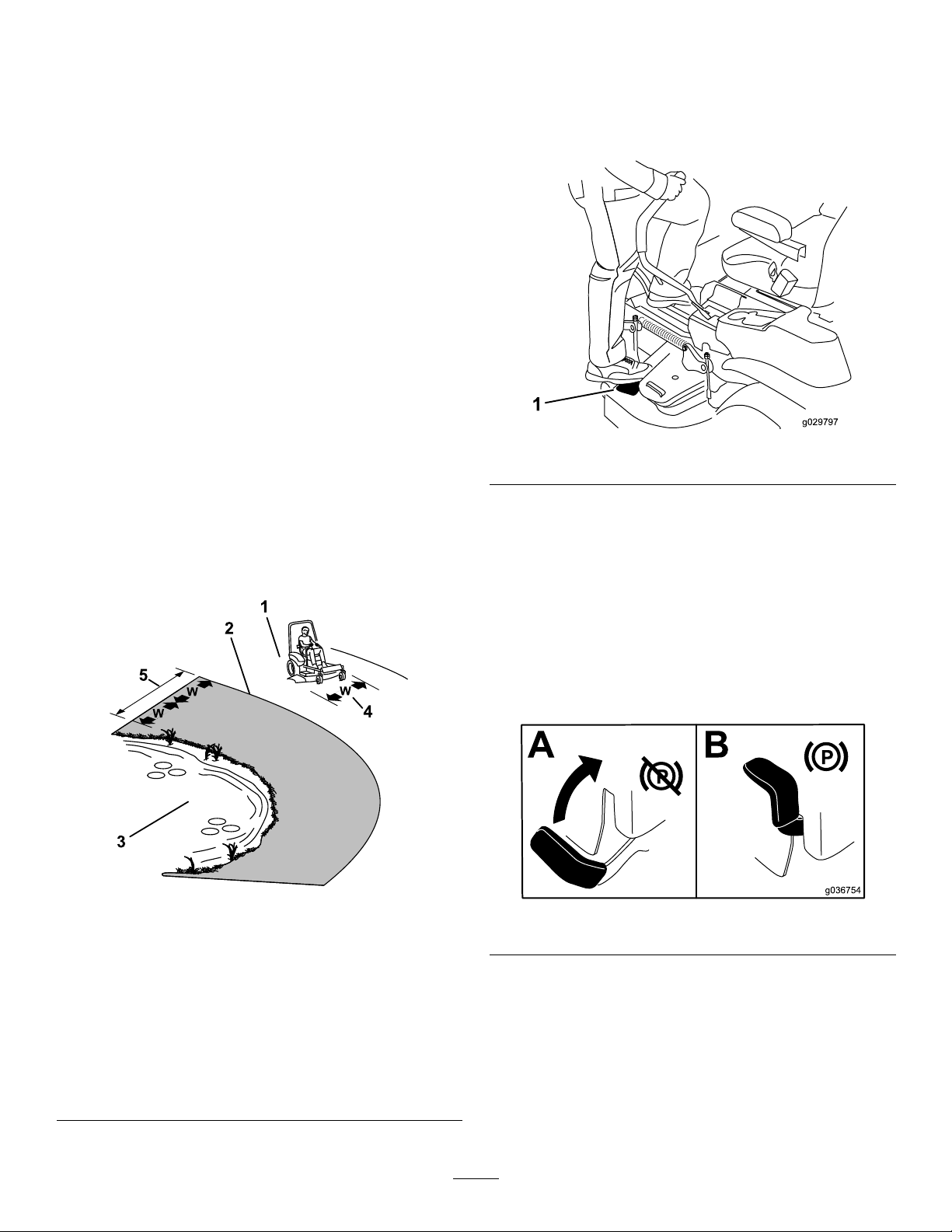
EnteringtheOperator’s Position
Usethemowerdeckasasteptogetintothe
operator’sposition(Figure19).
•Useextracarewhileoperatingwithaccessoriesor
attachments,suchasgrass-collectionsystems.
Thesecanchangethestabilityofthemachine
andcausealossofcontrol.Followdirectionsfor
counterweights.
•Ifpossible,keepthedeckloweredtotheground
whileoperatingonslopes.Raisingthedeckwhile
operatingonslopescancausethemachineto
becomeunstable.
g029797
Figure19
OperatingtheParking Brake
Alwaysengagetheparkingbrakewhenyoustopthe
machineorleaveitunattended.
EngagingtheParkingBrake
Parkthemachineonalevelsurface.
1.SafeZone—usethe
machinehereonslopes
lessthan15degreesor
atareas.
2.DangerZone—usea
walk-behindmowerand/or
ahandtrimmeronslopes
greaterthan15degrees
andneardrop-offsor
water.
3.Water
Figure18
g221745
g036754
Figure20
4.W=widthofthemachine
5.Keepasafedistance
(twicethewidthofthe
machine)betweenthe
machineandanyhazard.
25
Page 26
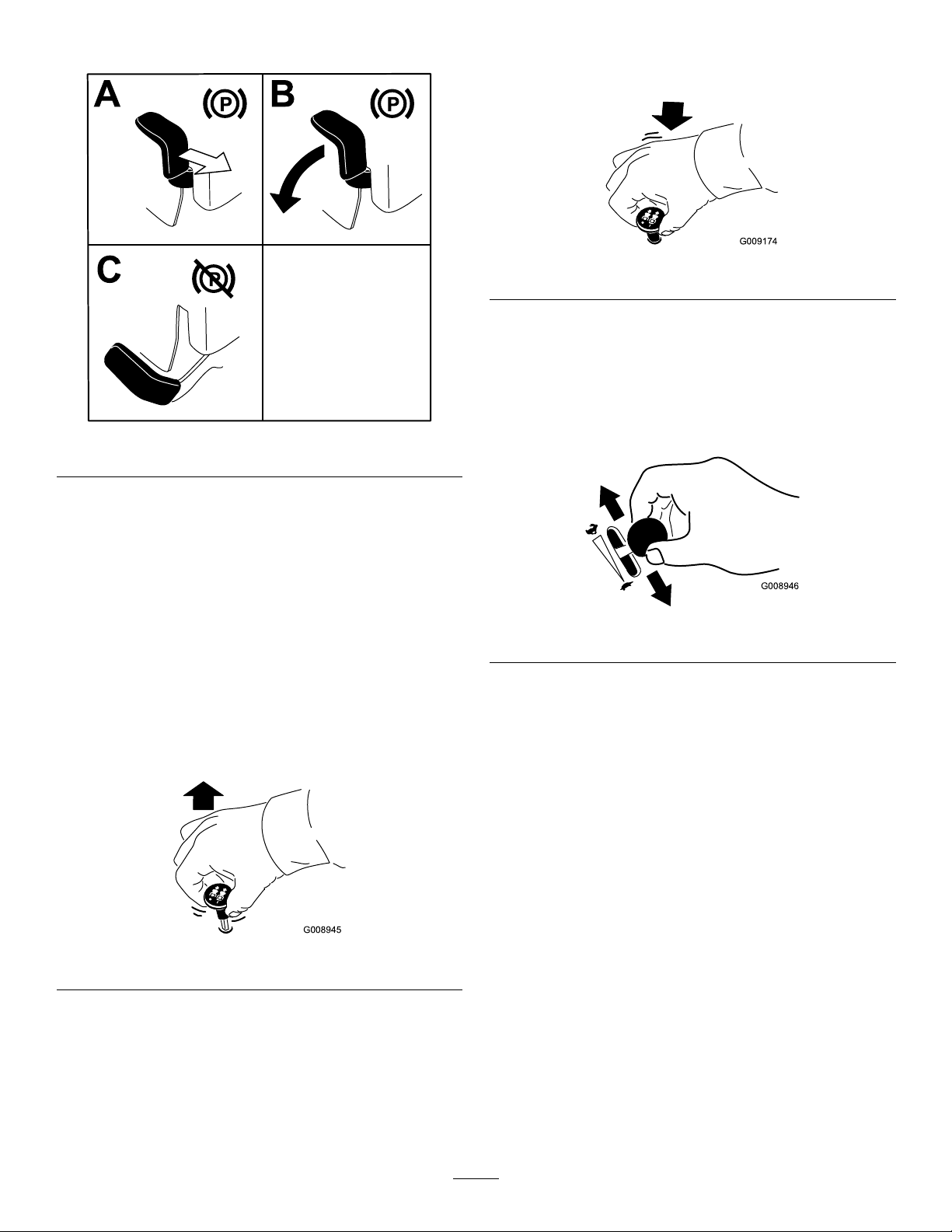
DisengagingtheParkingBrake
Figure21
DisengagingtheBlade-Control Switch(PTO)
g009174
Figure23
OperatingtheThrottle
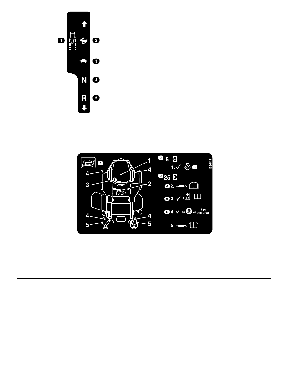
YoucanmovethethrottlecontrolbetweenFASTand
SLOWpositions(Figure24).
g192635
AlwaysusetheFASTpositionwhenengagingthePTO.
OperatingtheMower Blade-ControlSwitch(PTO)
Theblade-controlswitch(PTO)startsandstopsthe
mowerbladesandanypoweredattachments.
EngagingtheBlade-Control Switch(PTO)
Note:Engagingtheblade-controlswitch(PTO)with
thethrottlepositionathalforlesscausesexcessive
weartothedrivebelts.
Figure22
g008946
Figure24
g008945
26
Page 27
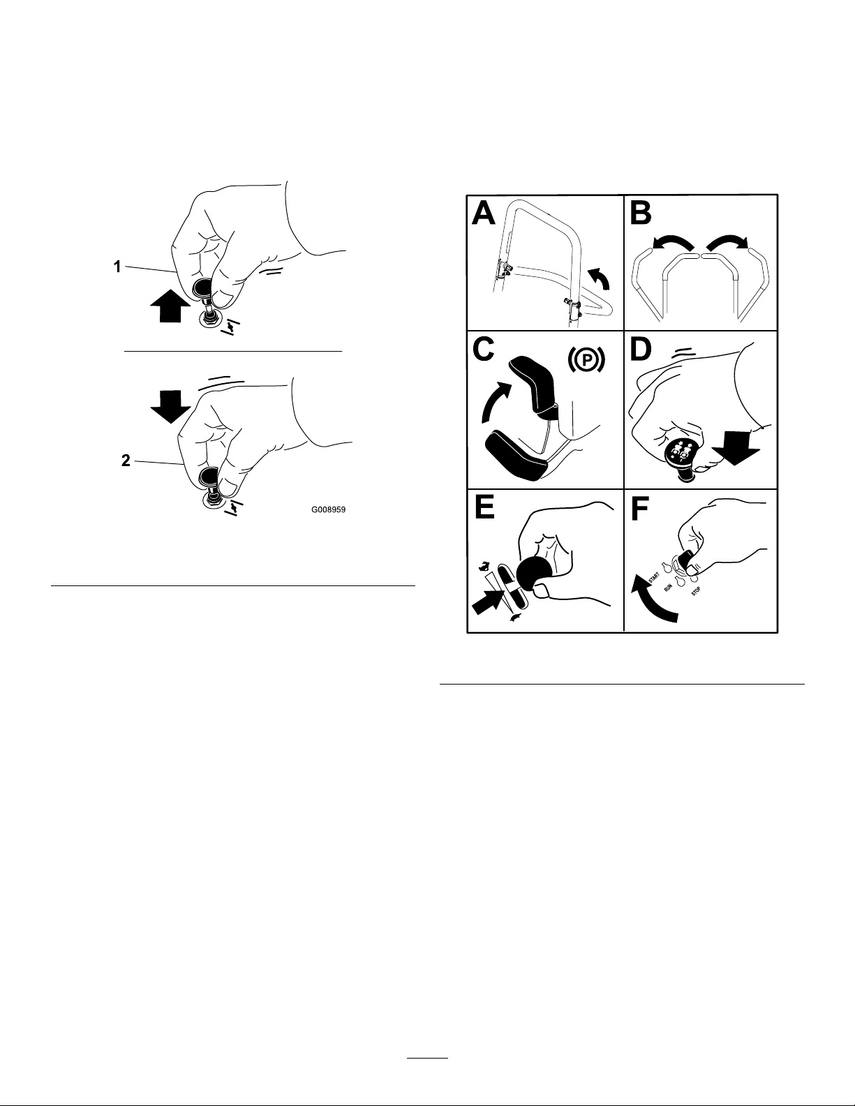
OperatingtheChoke
StartingtheEngine
Usethechoketostartacoldengine.
1.Pullupthechokeknobtoengagethechoke
beforeusingthekeyswitch(Figure25).
2.Pushdownthechokeknobtodisengagethe
chokeaftertheenginehasstarted(Figure25).
Note:Awarmorhotenginemaynotrequirechoking.
Important:Donotengagethestarterformore
than5secondsatatime.Engagingthestarter
motorformorethan5secondscandamagethe
startermotor.Iftheenginefailstostart,wait10
secondsbeforeoperatingtheenginestarteragain.
Figure25
1.ONposition2.OFFposition
g008959
g227548
Figure26
27
Page 28

ShuttingOfftheEngine
ShuttingOffKohlerEngines
Note:RefertoFigure45todeterminewhichengine
youhave.
CAUTION
Childrenorbystandersmaybeinjuredifthey
moveorattempttooperatethemachinewhile
itisunattended.
Alwaysremovethekeyandengagethe
parkingbrakewhenleavingthemachine
unattended.
ShuttingOffKawasakiEngines
Lettheengineidleatslowthrottlefor60seconds
beforeturningtheswitchoff.
Lettheengineidleatmid-throttlefor60seconds
beforeturningtheswitchoff.
Figure27
Important:Makesurethatthefuel-shutoff
valveisclosedbeforetransportingorstoring
themachinetopreventfuelleakage.Engage
theparkingbrakebeforetransporting.Remove
thekeyasthefuelpumpmayrunandcausethe
batterytolosecharge.
g231028
Figure28
Important:Makesurethatthefuel-shutoff
valveisclosedbeforetransportingorstoring
themachinetopreventfuelleakage.Engage
theparkingbrakebeforetransporting.Remove
thekeyasthefuelpumpmayrunandcausethe
batterytolosecharge.
g036839
28
Page 29

ShuttingOffToroEngines
UsingtheMotion-Control
Note:EnsurethethrottleisintheFASTposition
beforeshuttingofftheengine.
Levers
Figure29
Important:Makesurethatthefuel-shutoff
valveisclosedbeforetransportingorstoring
themachinetopreventfuelleakage.Engage
theparkingbrakebeforetransporting.Remove
thekeyasthefuelpumpmayrunandcausethe
batterytolosecharge.
c:\data\documentum\checkout\g004532
Figure30
g037049
1.Motion-control
lever—NEUTRAL-LOCK
position
2.Center,unlockedposition5.Frontofmachine
3.Forward
4.Backward
DrivingtheMachine
Thedrivewheelsturnindependently,poweredby
hydraulicmotorsoneachaxle.Youcanturn1side
inreversewhileyouturntheotherforward,causing
themachinetospinratherthanturn.Thisgreatly
improvesthemachinemaneuverabilitybutmay
requiresometimeforyoutoadapttohowitmoves.
Thethrottlecontrolregulatestheenginespeedas
measuredinrpm(revolutionsperminute).Place
thethrottlecontrolintheFASTpositionforbest
performance.Alwaysoperateinthefullthrottle
positionwhenmowing.
29
Page 30
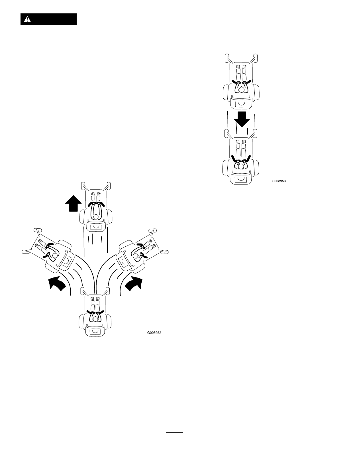
WARNING
Themachinecanspinveryrapidly.You
maylosecontrolofthemachineandcause
personalinjuryordamagetothemachine.
•Usecautionwhenmakingturns.
•Slowthemachinedownbeforemaking
sharpturns.
DrivingForward
Note:Theengineshutsoffwhenyoumovethe
traction-controlwiththeparkingbrakeengaged.
Tostopthemachine,pullthemotion-controllevers
totheNEUTRALposition.
1.Disengagetheparkingbrake;referto
DisengagingtheParkingBrake(page26).
2.Movetheleverstothecenter,unlockedposition.
3.T ogoforward,slowlypushthemotion-control
leversforward(Figure31).
DrivingBackward
1.Movetheleverstothecenter,unlockedposition.
2.T ogobackward,slowlypullthemotion-control
leversrearward(Figure32).
Figure31
g008953
Figure32
g008952
30
Page 31

AdjustingtheHeightofCut
UsingtheTransportLock
Thetransportlockhas2positions,andisusedwith
thedeck-liftpedal.ThereisaLOCKpositionand
anUNLOCKpositionforthetransportpositionofthe
mowerdeck(Figure33).
AdjustingtheHeight-of-CutPin
Adjusttheheight-of-cutfrom38to127mm(1-1/2to5
inches)in6mm(1/4inch)incrementsbymovingthe
height-of-cutpinintodifferentholelocations.
1.MovethetransportlocktotheLOCKposition.
2.Pushonthedeck-liftpedalwithyourfootand
raisethemowerdecktotheTRANSPORTposition
(alsothe127mmor5inchcutting-height
position)asshowninFigure34.
3.Removethepinfromtheheight-of-cutbracket
(Figure34).
4.Selectaholeintheheight-of-cutbracket
correspondingtotheheight-of-cutdesired,and
insertthepin(Figure34).
5.Pushonthedecklift,pulluponthetransport
lockknob,andslowlylowerthemowerdeck.
Figure33
Transport-LockPositions
1.Transportlockknob3.UNLOCKposition—The
2.LOCKposition—The
mowerdecklocksintothe
transportposition.
mowerdeckdoesnotlock
intothetransportposition.
g036745
Figure34
1.Deck-liftpedal3.Height-of-cutpin
2.Height-of-cutholes
g037050
AdjustingtheAnti-Scalp
4.Transportlockknob
Rollers
Wheneveryouchangetheheightofcut,adjustthe
heightoftheanti-scalprollers.
Note:Adjusttheanti-scalprollerssothattherollers
donottouchthegroundinnormal,atmowingareas.
1.Parkthemachineonalevelsurface,disengage
theblade-controlswitchandengagetheparking
brake;refertoEngagingtheParkingBrake
(page25).
2.Shutofftheengine,removethekey ,andwait
forallmovingpartstostopbeforeleavingthe
operatingposition.
31
Page 32

3.Adjusttheanti-scalprollersasshowninFigure
35orFigure36.
Figure35
2500Seriesmowerdeckshown
1.Anti-scalproller4.Flangenut
2.Spacer
3.Bushing
5.Bolt
AdjustingtheSideBumpers
Rear-DischargeMachinesOnly
Installthesidebumpersinthetopholeswhen
operatinginaheightofcuthigherthan64mm(2-1/2
inches)andinthecenterholeswhenoperatingina
heightofcutlowerthan64mm(2-1/2inches).
Note:Whenthebumpersbecomeworn,switchthe
bumperstotheoppositesidesofthemowerandip
themover.Thisallowsyoutousethebumperslonger
beforereplacingthem.
1.Parkthemachineonalevelsurface,disengage
g038079
theblade-controlswitchandengagetheparking
brake;refertoEngagingtheParkingBrake
(page25).
2.Shutofftheengine,removethekey ,andwait
forallmovingpartstostopbeforeleavingthe
operatingposition.
3.Raisethemowertothetransportposition.
4.Removetheboltsandnutsfromeachbumper
(Figure37).
Figure36
1500and2000Seriesmowerdeckshown
1.Flangenut4.Anti-scalproller
2.Bolt
3.Bushing
5.Spacer
g036848
g035120
Figure37
1.Bolt(3)3.Nut(3)
2.Bumper
5.Moveeachbumpertothedesiredpositionand
securethemwiththeboltsandnuts.
Note:Useonlythetoporcentersetsofholes
toadjustthebumpers.Youusethebottom
holeswhenswitchingsides,atwhichtimethey
becomethetopholesontheothersideofthe
mower.
32
Page 33

UsingtheSideDischarge
Themowerhasahingedgrassdeectorthat
dispersesclippingstothesideanddowntowardthe
turf.
DANGER
Withoutagrassdeector,dischargecover,or
acompletegrass-catcherassemblymounted
inplace,youandothersareexposedtoblade
contactandthrowndebris.Contactwith
rotatingmowerblade(s)andthrowndebris
willcauseinjuryordeath.
•Neverremovethegrassdeectorfromthe
mowerdeckbecausethegrassdeector
routesmaterialdowntowardtheturf.Ifthe
grassdeectoriseverdamaged,replaceit
immediately.
•Neverputyourhandsorfeetunderthe
mowerdeck.
•Nevertrytoclearthedischargearea
ormowerbladesunlessyoumovethe
blade-controlswitch(PTO)totheOFF
position,rotatethekeyswitchtotheOFF
position,andremovethekeyfromthekey
switch.
•Makesurethatthegrassdeectorisinthe
downposition.
grassissparse,oritislatefallwhengrassgrows
moreslowly.
AlternatingtheMowingDirection
Alternatethemowingdirectiontokeepthegrass
standingstraight.Thisalsohelpsdisperseclippings,
whichenhancesdecompositionandfertilization.
MowingatCorrectIntervals
Grassgrowsatdifferentratesatdifferenttimesof
theyear.Tomaintainthesamecuttingheight,mow
moreofteninearlyspring.Asthegrassgrowthrate
slowsinmidsummer,mowlessfrequently.Ifyou
cannotmowforanextendedperiod,rstmowata
highcuttingheight,thenmowagain2dayslaterata
lowerheightsetting.
UsingaSlowerCuttingSpeed
Toimprovecutquality ,useaslowergroundspeed
incertainconditions.
AvoidingCuttingTooLow
Whenmowinguneventurf,raisethecuttingheight
toavoidscalpingtheturf.
StoppingtheMachine
OperatingTips
UsingtheFastThrottleSetting
Forbestmowingandmaximumaircirculation,operate
theengineattheFASTposition.Airisrequiredto
thoroughlycutgrassclippings,sodonotsetthe
height-of-cutsolowastototallysurroundthemower
deckinuncutgrass.Alwaystrytohave1sideofthe
mowerdeckfreefromuncutgrass,whichallowsair
tobedrawnintothemowerdeck.
CuttingaLawnfortheFirstTime
Cutgrassslightlylongerthannormaltoensurethat
thecuttingheightofthemowerdeckdoesnotscalp
anyunevenground.However,thecuttingheight
usedinthepastisgenerallythebestonetouse.
Whencuttinggrasslongerthan15cm(6inches)tall,
youmaywanttocutthelawntwicetoensurean
acceptablequalityofcut.
CuttingaThirdoftheGrassBlade
Itisbesttocutonlyaboutathirdofthegrassblade.
Cuttingmorethanthatisnotrecommendedunless
Ifyoumuststoptheforwardmotionofthemachine
whilemowing,aclumpofgrassclippingsmay
dropontoyourlawn.Toavoidthis,moveontoa
previouslycutareawiththebladesengagedoryou
candisengagethemowerdeckwhilemovingforward.
KeepingtheUndersideofthe
MowerDeckClean
Cleanclippingsanddirtfromtheundersideofthe
mowerdeckaftereachuse.Ifgrassanddirtbuildup
insidethemowerdeck,cuttingqualitywilleventually
becomeunsatisfactory.
MaintainingtheBlade(s)
Maintainasharpbladethroughoutthecuttingseason
becauseasharpbladecutscleanlywithouttearingor
shreddingthegrassblades.Tearingandshredding
turnsgrassbrownattheedges,whichslowsgrowth
andincreasesthechanceofdisease.Checkthe
mowerbladesaftereachuseforsharpness,and
foranywearordamage.Filedownanynicksand
sharpenthebladesasnecessary .Ifabladeis
damagedorworn,replaceitimmediatelywitha
genuineT ororeplacementblade.
33
Page 34

AfterOperation
AfterOperationSafety
UsingtheDrive-Wheel ReleaseValves
WARNING
GeneralSafety
•Cleangrassanddebrisfromthecuttingunits,
mufers,andenginecompartmenttohelpprevent
res.Cleanupoilorfuelspills.
•Shutoffthefuelandremovethekeybeforestoring
ortransportingthemachine.
•Disengagethedrivetotheattachmentwhenever
youaretransportingornotusingthemachine.
•Allowtheenginetocoolbeforestoringthemachine
inanyenclosure.
•Neverstorethemachineorfuelcontainerwhere
thereisanopename,spark,orpilotlight,such
asonawaterheateroronotherappliances.
UsingtheFuel-Shutoff Valve
Closethefuel-shutoffvalvefortransport,maintenance,
andstorage(Figure38).
Ensurethatthefuel-shutoffvalveisopenwhen
startingtheengine.
Handsmaybecomeentangledintherotating
drivecomponentsbelowtheenginedeck,
whichcouldresultinseriousinjury.
Shutofftheengine,removethekey,andallow
allmovingpartstostopbeforeaccessingthe
drive-wheelreleasevalves.
WARNING
Theengineandhydraulic-driveunitscan
becomeveryhot.Touchingahotengineor
hydraulic-driveunitscancausesevereburns.
Allowtheengineandhydraulic-driveunits
tocoolcompletelybeforeaccessingthe
drive-wheelreleasevalves.
Thedrive-wheelreleasevalvesarelocatedontheleft
andrightsidesunderneaththeenginedeck.
1.Parkthemachineonalevelsurface,disengage
theblade-controlswitch,andengagetheparking
brake.
2.Shutofftheengine,removethekey ,andwait
forallmovingpartstostopbeforeleavingthe
operatingposition.
Figure38
1.ONposition2.OFFposition
3.Locatethebypassleversbehindtheseat,down
ontheleftandrightsideoftheframe.
4.T opushthemachine,movebothbypassknobs
g036849
g008948
rearwardandlockthemintoplace(Figure39).
5.Disengagetheparkingbrakebeforepushing
themachine.
34
Page 35

TransportingtheMachine
Useaheavy-dutytrailerortrucktotransportthe
machine.Useafull-widthramp.Ensurethatthetrailer
ortruckhasallthenecessarybrakes,lighting,and
markingasrequiredbylaw.Pleasecarefullyreadall
thesafetyinstructions.Knowingthisinformationcould
helpyouorbystandersavoidinjury.Refertoyour
localordinancesfortrailerandtie-downrequirements.
WARNING
Drivingonthestreetorroadwaywithout
turnsignals,lights,reectivemarkings,ora
slow-moving-vehicleemblemisdangerous
andcanleadtoaccidents,causingpersonal
injury.
Donotdrivethemachineonapublicstreet
orroadway.
Figure39
1.Frontofthemachine
2.Rotatebypassreleaseknobcounterclockwisetoloosen.
3.Leverpositionforoperatingthemachine
4.Pulltheleverinthisdirectiontopushthemachine.
5.Leverpositionforpushingthemachine
6.Rotatethebypass-releaseknobclockwisetotighten.
7.Engine
8.Releaselever
6.T orunthemachine,movethebypassknobsto
theFORWARDpositionandlockthemintoplace
(Figure39).
g035062
SelectingaTrailer
WARNING
Loadingamachineontoatrailerortruck
increasesthepossibilityoftip-overandcould
causeseriousinjuryordeath(Figure40).
•Useonlyafull-widthramp;donotuse
individualrampsforeachsideofthe
machine.
•Donotexceeda15-degreeanglebetween
therampandthegroundorbetweenthe
rampandthetrailerortruck.
•Ensurethatthelengthoframpisatleast4
timesaslongastheheightofthetraileror
truckbedtotheground.Thisensuresthat
rampangledoesnotexceed15degreeson
atground.
35
Page 36

1.Ifusingatrailer,connectittothetowingvehicle
andconnectthesafetychains.
2.Ifapplicable,connectthetrailerbrakesand
lights.
3.Lowertheramp,ensuringthattheangle
betweentherampandthegrounddoesnot
exceed15degrees(Figure40).
4.Backthemachineuptheramp(Figure41).
Figure41
g028043
1.Full-widthrampinstowed
position
2.Sideviewoffull-width
rampinloadingposition
3.Notgreaterthan
15degrees
LoadingtheMachine
Figure40
4.Rampisatleast4times
aslongastheheightof
thetrailerortruckbedto
theground
5.H=heightofthetraileror
truckbedtotheground
6.Trailer
1.Backthemachineupthe
ramp.
2.Drivethemachineforward
downtheramp.
5.Shutofftheengine,removethekey,andengage
theparkingbrake.
6.Tiedownthemachinenearthefrontcaster
wheelsandtherearbumperwithstraps,chains,
cable,orropes(Figure42).Refertolocal
regulationsfortie-downrequirements.
g027996
WARNING
Loadingamachineontoatrailerortruck
increasesthepossibilityoftip-overandcould
causeseriousinjuryordeath.
•Useextremecautionwhenoperatinga
machineonaramp.
•Backthemachineuptherampanddriveit
forwarddowntheramp.
•Avoidsuddenaccelerationordeceleration
whiledrivingthemachineonarampas
thiscouldcausealossofcontrolora
tip-oversituation.
g231449
Figure42
1.Tie-downloops
UnloadingtheMachine
1.Lowertheramp,ensuringthattheangle
betweentherampandthegrounddoesnot
exceed15degrees(Figure40).
2.Drivethemachineforwarddowntheramp
(Figure41).
36
Page 37

Maintenance
RecommendedMaintenanceSchedule(s)
MaintenanceService
Interval
Aftertherst5hours
Aftertherst75hours
Beforeeachuseordaily
Every25hours
MaintenanceProcedure
•ForToroengines—changetheengineoilandlter.
•Changethehydraulic-systemltersanduid.
•Checkthesafety-interlocksystem.
•ForKawasakiengines—checktheengine-oillevel.
•ForKohlerengines—checktheaircleanerfordirty,loose,ordamagedparts.
•ForKohlerengines—checktheengine-oillevel.
•Cleantheblowerhousing(moreoftenunderdusty,dirtyconditions).
•ForToroengines—checktheengine-oillevel.
•Cleantheairintakescreen.
•Checktheseatbelt.
•Checktherollbarknobs.
•Cleantheenginescreenandtheareaaroundtheengine.
•Cleanaroundtheengine-exhaustsystem.
•Checkthehydraulicuidlevelintheexpansiontank.
•Inspecttheblades.
•Cleanthemowerdeck.
•Cleanthesuspensionsystem.
•Greasethefrontcasteraxles.(moreoftenindirtyordustyconditions).
•ForKohlerengines—serviceorreplacetheair-cleanerfoamelement(moreoften
underdusty,dirtyconditions).
•ForToroengineswithastandardaircleaner—cleantheair-cleanerfoamelement
(moreoftenindusty,dirtyconditions).
Every50hours
Every100hours
Every200hours
•Greasethepump-idlerpivot.
•Checkthesparkarrester(ifequipped).
•Checkthetirepressure.
•Inspectthebeltsforcracksandwear.
•ForKawasakiengines—changetheengineoil(moreoftenindirtyordusty
conditions).
•ForKawasakiengines—replaceorcleanandgapthesparkplug.
•ForKohlerengines—replacetheair-cleanerpaperelement(moreoftenunderdusty ,
dirtyconditions).
•ForKohlerengines—changetheengineoilandtheengine-oillter.
•ForKohlerengines—cleanthecoolingns(moreoftenunderdusty,dirtyconditions).
•ForT oroengineswithastandardaircleaner—replacetheair-cleanerfoamelement
(moreoftenindusty,dirtyconditions).
•ForT oroengineswithastandardaircleaner—servicetheair-cleanerpaperelement
(moreoftenindusty,dirtyconditions).
•ForToroengines—changetheengineoilandoillter(moreoftenindusty,dirty
conditions).
•ForToroengines—checkthesparkplug(s).
•ForKawasakiengines—changetheengine-oillter(moreoftenindirtyordusty
conditions).
•ForKohlerengines—checkthesparkplug(s).
•ForT oroengineswithastandardaircleaner—replacetheair-cleanerpaperelement
(moreoftenindusty,dirtyconditions).
•ForToroengines—replacethesparkplug(s).
37
Page 38

MaintenanceService
Every250hours
Interval
MaintenanceProcedure
•ForKawasakiengines—replacetheprimaryairlter(moreoftenindustyorsandy
conditions).
•ForKawasakiengines—checkthesafetyairlter(moreoftenindustyorsandy
conditions).
•ForToroengineswithaheavy-dutyaircleaner—replacetheairlter(moreoften
industyorsandyconditions).
•Aftertheinitialchange—changethehydraulic-systemltersanduidwhenusing
Mobil115W50uid(changeitmoreoftenundersevereconditions).
Every300hours
Every500hours
Monthly
Yearly
Yearlyorbeforestorage
•ForKawasakiengines—Checkandadjustthevalveclearance.SeeanAuthorized
ServiceDealer.
•ForKawasakiengines—replacethesafetyairlter(moreoftenindustyorsandy
conditions).
•ForKohlerengines—Checkandadjustthevalveclearance.SeeanAuthorized
ServiceDealer.
•ForKohlerengines—replacethesparkplug(s).
•Replacetheemissions-airintakelter.
•Replacethefuellter(moreoftenindusty,dirtyconditions).
•Checktheparkingbrakeadjustment.
•Aftertheinitialchange—changethehydraulic-systemltersanduidwhenusing
Toro®HYPR-OIL™500uid(changeitmoreoftenundersevereconditions).
•Checkthebatterycharge.
•For2500Seriesmachines—Lubricatethecaster-wheelhubs.
•Paintchippedsurfaces.
•Checkallmaintenanceprocedureslistedabovebeforestorage.
Important:Refertoyourengineowner'smanualforadditionalmaintenanceprocedures.
CAUTION
Ifyouleavethekeyintheswitch,someonecouldaccidentlystarttheengineandseriously
injureyouorotherbystanders.
Shutofftheengineandremovethekeyfromtheswitchbeforeyouperformanymaintenance.
Pre-Maintenance
Procedures
MaintenanceSafety
•Beforerepairingthemachinedothefollowing:
–Disengagethedrives.
–Engagetheparkingbrake.
–Shutofftheengineandremovethekey.
–Disconnectthespark-plugwire.
•Parkthemachineonalevelsurface.
•Cleangrassanddebrisfromthecuttingunit,
drives,mufers,andenginetohelppreventres.
•Cleanupoilorfuelspills.
•Donotallowuntrainedpersonneltoservicethe
machine.
•Usejackstandstosupportthemachineand/or
componentswhenrequired.
•Carefullyreleasepressurefromcomponentswith
storedenergy.
•Disconnectthebatteryorremovethespark-plug
wirebeforemakinganyrepairs.Disconnectthe
negativeterminalrstandthepositiveterminal
last.Connectthepositiveterminalrstand
negativelast.
•Usecarewhencheckingtheblades.Wrapthe
blade(s)orwearthicklypaddedgloves,anduse
cautionwhenservicingthem.Onlyreplaceblades;
donotstraightenorweldthem.
•Keepyourhandsandfeetawayfrommoving
parts.Ifpossible,donotmakeadjustmentswith
theenginerunning.
•Keepallpartsingoodworkingcondition
andallhardwaretightened,especiallythe
blade-attachmentbolts.Replaceallwornor
damageddecals.
•Neverinterferewiththeintendedfunctionofa
safetydeviceorreducetheprotectionprovided
38
Page 39

byasafetydevice.Checktheirproperoperation
regularly.
•UseonlygenuineTororeplacementparts.
•Checktheparkingbrakeoperationfrequently.
Adjustandserviceasrequired.
Lubrication
GreasingtheMachine
ServiceInterval:Every25hours—Greasethefront
casteraxles.(moreoftenindirtyor
dustyconditions).
Every50hours—Greasethepump-idlerpivot.
GreaseType:No.2lithiumormolybdenumgrease
1.Parkthemachineonalevelsurface,disengage
theblade-controlswitch,andengagetheparking
brake;refertoEngagingtheParkingBrake
(page25).
2.Shutofftheengine,removethekey ,andwait
forallmovingpartstostopbeforeleavingthe
operatingposition.
3.Cleanthegreasettingswitharag.
Note:Scrapeanypaintoffthefrontofthe
tting(s).
4.Greasethepumpidler-pulleypivotwith1or2
pumpsofgrease(Figure43).
5.Greasethefrontcasteraxles(Figure43).
Figure43
1.Pump-idlerpivot
6.Wipeupanyexcessgrease.
2.Casteraxle
g188563
39
Page 40

Lubricatingthe Caster-WheelHubs
2500SeriesMachinesOnly
ServiceInterval:Yearly—For2500Series
machines—Lubricatethe
caster-wheelhubs.
1.Parkthemachineonalevelsurface,disengage
theblade-controlswitch,andengagetheparking
brake.
2.Shutofftheengine,removethekey ,andwait
forallmovingpartstostopbeforeleavingthe
operatingposition.
3.Removethecasterwheelfromthecasterforks.
4.Removethesealguardsfromthewheelhub
(Figure44).
approximately3mm(1/8inch)fromtheouter
surfaceofthespacernuttotheendoftheaxle
insidethenut.
11.Inserttheassemblednutandaxleintothewheel
onthesidewiththenewsealandbearing.
12.Withtheopenendofthewheelfacingup,ll
theareainsidethewheelaroundtheaxlefullof
general-purposegrease.
13.Insertthesecondbearingandnewsealintothe
wheel.
14.Applyathread-lockingcompoundtothesecond
spacernutandthreaditontotheaxlewiththe
wrenchatsfacingoutward.
15.T orquethenutto8to9N∙m(75to80in-lb),
loosenthenut,thentorqueitto2to3N∙m(20
to25in-lb).
Note:Makesurethattheaxledoesnotextend
beyondeithernut.
16.Installthesealguardsoverthewheelhuband
insertwheelintothecasterfork.
Figure44
1.Sealguard2.Spacernutwithwrench
ats
5.Removeaspacernutfromtheaxleassemblyin
thecasterwheel.
Note:Thread-lockingcompoundhasbeen
appliedtolockthespacernutstotheaxle.
6.Removetheaxle(withtheotherspacernutstill
assembledtoit)fromthewheelassembly.
7.Pryoutsealsandinspectbearingsforwearor
damageandreplaceifnecessary.
8.Packthebearingswithageneral-purpose
grease.
17.Installthecasterboltandtightenthenutfully.
Important:Topreventsealandbearingdamage,
checkthebearingadjustmentoften.Spinthe
castertire.Thetireshouldnotspinfreely(more
than1or2revolutions)orhaveanysideplay.If
g006115
thewheelspinsfreely,adjustthetorqueonthe
spacernutuntilthereisaslightamountofdrag.
Applyanotherlayerofthread-lockingcompound.
9.Insert1bearingand1newsealintothewheel.
Note:Replacetheseals.
10.Ifbothspacernutshavebeenremoved(or
brokenloose)fromtheaxleassembly,applya
thread-lockingcompoundto1spacernutand
threaditontotheaxlewiththewrenchats
facingoutward.
Note:Donotthreadthespacernutallof
thewayontotheendoftheaxle.Leave
40
Page 41

EngineMaintenance
IdentifyingtheEngine
Usethefollowinggraphictoidentifytheengineyouhaveandproceedtothesectionlistedbelowforservice
(Figure45).
Figure45
1.Kawasakiengine3.T oroenginewithstandardaircleaner
2.Kohlerengine4.T oroenginewithheavy-dutyaircleaner
g231391
•ForKawasakienginemaintenance,refertoServicingaKawasaki
•ForKohlerenginemaintenance,refertoServicingaKohler
®
Engine(page41).
®
Engine(page46).
•ForT oroenginemaintenance,refertoServicingaToroEngine(page51).
EngineSafety
•Shutofftheenginebeforecheckingtheoilor
addingoiltothecrankcase.
•Keepyourhands,feet,face,clothing,andother
bodypartsawaythemuferandotherhotsurfaces.
ServicingaKawasaki
Engine
ThissectionisonlyformachineswithKawasaki
engines.Ifyourenginelooksliketheoneshownin
Figure46,youhaveaKawasakiengine.
Important:Refertoyourengineowner’smanual
foradditionalmaintenanceprocedures.
®
g036714
Figure46
41
Page 42

ServicingtheAirCleaner
ServiceInterval:Every250hours—ForKawasaki
engines—replacetheprimaryair
lter(moreoftenindustyorsandy
conditions).
Every250hours—ForKawasaki
engines—checkthesafetyairlter(moreoften
industyorsandyconditions).
Every500hours—ForKawasaki
engines—replacethesafetyairlter
(moreoftenindustyorsandyconditions).
Note:Checktheltersmorefrequentlyifthe
operatingconditionsareextremelydustyorsandy .
RemovingtheFilters
1.Parkthemachineonalevelsurface,disengage
theblade-controlswitch(PTO),andengagethe
parkingbrake.
2.Shutofftheengine,removethekey ,andwait
forallmovingpartstostopbeforeleavingthe
operatingposition.
3.Releasethelatchesontheaircleanerandpull
theair-cleanercoverofftheair-cleanerbody
(Figure47).
Important:Donotattempttocleanthe
safetylter.Ifthesafetylterisdirty ,then
theprimarylterisdamaged.Replaceboth
lters.
7.Inspecttheprimarylterfordamagebylooking
intothelterwhileshiningabrightlightonthe
outsideofthelter.
Note:Holesinthelterappearasbrightspots.
Ifthelterisdamaged,discardit.
InspectingtheFilters
1.Inspectthesafetylter.Ifitisdirty ,replaceboth
thesafetyandprimarylters.
Important:Donotattempttocleanthe
safetylter.Ifthesafetylterisdirty ,then
theprimarylterisdamaged.
2.Inspecttheprimarylterfordamagebylooking
intothelterwhileshiningabrightlightonthe
outsideofthelter.Iftheprimarylterisdirty,
bent,ordamaged,replaceit.
Note:Holesinthelterappearasbrightspots.
Donotcleantheprimarylter.
InstallingtheFilters
Figure47
1.Air-cleanerbody4.Air-cleanercover
2.Primarylter5.Safetylter
3.Latch
4.Cleantheinsideoftheair-cleanercoverwith
compressedair.
5.Gentlyslidetheprimarylteroutofthe
air-cleanerbody(Figure47).
Important:Topreventenginedamage,always
operatetheenginewithbothairltersandthe
coverinstalled.
1.Ifyouareinstallingnewlters,checkeachlter
forshippingdamage.
Note:Donotuseadamagedlter.
2.Ifyouarereplacingtheinnerlter,carefullyslide
itintothelterbody(Figure47).
3.Carefullyslidetheprimarylteroverthesafety
lter(Figure47).
Note:Ensurethattheprimarylterisfully
g001883
seatedbypushingontheouterrimwhile
installingit.
Important:Donotpressonthesoft,inside
areaofthelter.
4.Installtheair-cleanercoverandsecurethe
latches(Figure47).
Note:Avoidknockingthelterintothesideof
thebody.
6.Removethesafetylteronlytoreplaceit.
42
Page 43

ServicingtheEngineOil
Engine-OilSpecications
OilType:Detergentoil(APIserviceSF ,SG,SH,SJ,
orSL)
CrankcaseCapacity:1.8L(61oz)withouttheoil
lter;2.1L(71oz)withtheoillter
Viscosity:Seethetablebelow.
g036856
Figure48
Note:Although10W-40engineoilisrecommended
formostconditions,youmayneedtochangeoil
viscositytoaccommodateatmosphericconditions.
Using20W-50engineoilinhigherambient
temperaturescanreduceoilconsumption.
CheckingtheEngine-OilLevel
ServiceInterval:Beforeeachuseordaily
Note:Checktheoilwhentheengineiscold.
Important:Ifyouoverllorunderlltheengine
crankcasewithoilandruntheengine,youmay
damagetheengine.
1.Parkthemachineonalevelsurface,disengage
theblade-controlswitch(PTO),andengagethe
parkingbrake.
2.Shutofftheengine,removethekey ,andwait
forallmovingpartstostopbeforeleavingthe
operatingposition.
Note:Ensurethattheengineiscoolsothatthe
oilhashadtimetodrainintothesump.
3.T okeepdirt,grassclippings,andotherdebris,
outoftheengine,cleantheareaaroundthe
oil-llcapanddipstickbeforeremovingit(Figure
49).
g037096
g029368
Figure49
ChangingtheEngineOil
ServiceInterval:Every100hours(moreoftenindirty
ordustyconditions).
Note:Disposeoftheusedoilatarecyclingcenter.
1.Starttheengineandletitrunfor5minutes.
Note:Thiswarmstheoilsothatitdrainsbetter.
2.Parkthemachinesothatthedrainsideisslightly
lowerthantheoppositesidetoensurethatthe
oildrainscompletely.
43
Page 44

3.Disengagetheblade-controlswitch(PTO)and
engagetheparkingbrake.
4.Shutofftheengine,removethekey ,andwait
forallmovingpartstostopbeforeleavingthe
operatingposition.
5.Draintheoilfromtheengine(Figure50).
6.Slowlypourapproximately80%ofthespecied
oilintothellertubeandslowlyaddthe
additionaloiltobringittotheFullmark(Figure
51).
g036856
Figure50
g027660
Figure51
7.Starttheengineanddrivetoaatarea.
8.Checktheoillevelagain.
g027734
44
Page 45

ChangingtheEngine-OilFilter
ServicingtheSparkPlug
ServiceInterval:Every200hours—ForKawasaki
engines—changetheengine-oil
lter(moreoftenindirtyordusty
conditions).
1.Draintheoilfromtheengine;refertoChanging
theEngineOil(page43).
2.Changetheengine-oillter(Figure52).
ServiceInterval:Every100hours
Ensurethattheairgapbetweenthecenterandside
electrodesiscorrectbeforeinstallingthesparkplug.
Useasparkplugwrenchforremovingandinstalling
thesparkplugandagappingtoolorfeelergaugeto
checkandadjusttheairgap.Installanewsparkplug
ifnecessary.
TypeofSparkPlug:NGK
®
BPR4ESorequivalent
AirGap:0.75mm(0.03inch)
RemovingtheSparkPlug
1.Parkthemachineonalevelsurface,disengage
theblade-controlswitch(PTO),andengagethe
g036856
parkingbrake.
2.Shutofftheengine,removethekey ,andwait
forallmovingpartstostopbeforeleavingthe
operatingposition.
3.Cleantheareaaroundthebaseoftheplug(s)to
keepdirtanddebrisoutoftheengine.
4.Locateandremovethesparkplug(s)asshown
inFigure53.
Figure52
Note:Ensurethattheoil-ltergaskettouches
theengine,andthenturntheoillteranextra
3/4turn.
3.Fillthecrankcasewiththepropertypeofnew
oil;refertoServicingtheEngineOil(page43).
g036857
g027478
Figure53
g027477
45
Page 46

CheckingtheSparkPlug
Important:Donotcleanthesparkplug(s).
Alwaysreplacethesparkplug(s)whenithasa
blackcoating,wornelectrodes,anoilylm,or
cracks.
Ifyouseelightbrownorgrayontheinsulator,the
engineisoperatingproperly.Ablackcoatingonthe
insulatorusuallymeanstheaircleanerisdirty .
Setthegapto0.75mm(0.03inch).
Figure54
InstallingtheSparkPlug
ServicingaKohler
ThissectionisonlyformachineswithKohlerengines.
IfyourenginelooksliketheoneshowninFigure56,
youhaveaKohlerengine.
®
Engine
Important:Refertoyourengineowner’smanual
foradditionalmaintenanceprocedures.
g206628
g036713
Figure56
Figure55
ServicingtheAirCleaner
ServiceInterval:Beforeeachuseordaily—For
Kohlerengines—checktheair
cleanerfordirty,loose,ordamaged
parts.
Every25hours—ForKohlerengines—service
orreplacetheair-cleanerfoamelement(more
oftenunderdusty ,dirtyconditions).
Every100hours—ForKohlerengines—replace
theair-cleanerpaperelement(moreoftenunder
dusty,dirtyconditions).
g027661
Thisengineisequippedwithareplaceable,
high-densitypaperandfoamair-cleanerelement.
Checktheaircleanerdailyorbeforestartingthe
engine.Checkforabuildupofdirtanddebrisaround
theair-cleanersystem.Keepthisareaclean.Also,
checkforlooseordamagedcomponents.Replaceall
bentordamagedair-cleanercomponents.
Note:Operatingtheenginewithlooseordamaged
air-cleanercomponentscouldallowunlteredairinto
theengine,causingprematurewearandfailure.
Note:Servicetheaircleanermoreoftenunderdusty ,
dirtyconditions.
46
Page 47

RemovingtheElements
1.Rotatethelatchesoutward.
ServicingthePaperElement
1.Gentlytapthepaperelementtodislodgedirt.
2.Removethecovertoaccesstheair-cleaner
elements(Figure57).
Figure57
1.Air-cleanercover2.Air-cleanerlatch
3.Removethefoamandpaperelements(Figure
58).
4.Removethefoamelementfromthepaper
element(Figure58).
Note:Donotwashthepaperelementoruse
pressurizedair,asthiswilldamagetheelement.
Note:Replaceadirty,bent,ordamaged
element.Handlethenewelementcarefully;
donotuseifthesealingsurfacesarebentor
damaged.
2.Cleantheair-cleanerbaseasrequired,and
checkthecondition.
InstallingtheElements
1.Installthefoamelementontothepaperelement.
2.Installtheelementsontotheair-cleanerbase
(Figure58).
3.Installthecover,andsecureitwiththelatches
(Figure57).
g028105
ServicingtheEngineOil
EngineOilSpecications
OilType:Detergentoil(APIserviceSJorhigher)
CrankcaseCapacity:1.9L(64oz)withtheoillter
Viscosity:Seethetablebelow.
Figure58
1.Air-cleanercover3.Paperelement
2.Foamelement
ServicingtheFoamElement
1.Washthefoamelementinliquidsoapand
warmwater.Whentheelementisclean,rinse
itthoroughly.
2.Drytheelementbysqueezingitinacleancloth.
Important:Replacethefoamelementifit
istornorworn.
g028106
g017552
Figure59
CheckingtheEngine-OilLevel
ServiceInterval:Beforeeachuseordaily
Note:Checktheoilwhentheengineiscold.
Important:Ifyouoverllorunderlltheengine
crankcasewithoilandruntheengine,youmay
damagetheengine.
1.Parkthemachineonalevelsurface,disengage
theblade-controlswitch(PTO),andengagethe
parkingbrake.
47
Page 48

2.Shutofftheengine,removethekey ,andwait
forallmovingpartstostopbeforeleavingthe
operatingposition.
Note:Ensurethattheengineiscoolsothatthe
oilhashadtimetodrainintothesump.
3.T okeepdirt,grassclippings,etc.,outofthe
engine,cleantheareaaroundtheoil-llcapand
dipstickbeforeremovingit(Figure49).
ChangingtheEngineOilandtheEngine-Oil
Filter
ServiceInterval:Every100hours—ForKohler
engines—changetheengineoiland
theengine-oillter.
Note:Thedrainplugisattachedtothedrainhose.
1.Parkthemachinesothatthedrainsideisslightly
lowerthantheoppositesidetoensurethatthe
oildrainscompletely.
2.Disengagetheblade-controlswitch(PTO)and
engagetheparkingbrake.
3.Shutofftheengine,removethekey ,andwait
forallmovingpartstostopbeforeleavingthe
operatingposition.
4.Draintheoilfromtheengine.
Figure60
g027515
g027934
Figure61
5.T orquetheplugto14N·m(125in-lb).
48
Page 49

Figure62
6.Slowlypourapproximately80%ofthespecied
oilintothellertubeandslowlyaddthe
additionaloiltobringittotheFullmark(Figure
63).
g027517
Figure63
7.Disposetheusedoilatarecyclingcenter.
g028127
49
Page 50

ServicingtheSparkPlug
ServiceInterval:Every200hours—ForKohler
engines—checkthesparkplug(s).
Every500hours—ForKohlerengines—replace
thesparkplug(s).
ThesparkplugisRFIcompliant;youcanalsouse
anequivalentplug.
Type:ChampionXC12YC
AirGap:0.76mm(0.03inch)
RemovingtheSparkPlug
1.Parkthemachineonalevelsurface,disengage
theblade-controlswitch(PTO),andengagethe
parkingbrake.
2.Shutofftheengine,removethekey ,andwait
forallmovingpartstostopbeforeleavingthe
operatingposition.
3.Cleantheareaaroundthebaseoftheplugto
keepdirtanddebrisoutoftheengine.
g206628
Figure65
InstallingtheSparkPlug
4.Removethesparkplug(Figure64).
Figure64
CheckingtheSparkPlug
Important:Donotcleanthesparkplug(s).
Alwaysreplacethesparkplug(s)whenithasa
blackcoating,wornelectrodes,anoilylm,or
cracks.
Ifyouseelightbrownorgrayontheinsulator,the
engineisoperatingproperly.Ablackcoatingonthe
insulatorusuallymeanstheaircleanerisdirty .
Setthegapto0.76mm(0.03inch).
g028109
Figure66
g027478
CleaningtheBlowerHousing
Every100hours/Y early(whichevercomes
rst)—ForKohlerengines—cleanthecooling
ns(moreoftenunderdusty,dirtyconditions).
Toensurepropercooling,ensurethatthegrass
screen,coolingns,andotherexternalsurfacesofthe
enginearekeptcleanatalltimes.
ForKohlerengines,removetheblowerhousing,and
anyothercoolingshrouds.Cleanthecoolingnsand
externalsurfacesasnecessary.Makesurethatthe
coolingshroudsareinstalled.
Important:Operatingtheenginewithablocked
grassscreen,dirtyorpluggedcoolingns,and/or
coolingshroudsremoved,willcauseengine
damageduetooverheating.
50
Page 51

ServicingaToroEngine
ThissectionisonlyformachineswithToroengines.
Ifyourenginelookslike1ofthe2enginesshownin
Figure67,youhaveaToroengine.
Figure67
g027800
g231404
1.Standardaircleaner
2.Heavy-dutyaircleaner
ServicingtheAirCleaner
EngineswithaStandardAirCleaner
ServiceInterval:Every25hours/Monthly(whichever
comesrst)—ForToroengineswith
astandardaircleaner—cleanthe
air-cleanerfoamelement(more
oftenindusty,dirtyconditions).
Every100hours/Y early(whichevercomes
rst)—ForToroengineswithastandardair
cleaner—replacetheair-cleanerfoamelement
(moreoftenindusty,dirtyconditions).
Every100hours/Y early(whichevercomes
rst)—ForToroengineswithastandardair
cleaner—servicetheair-cleanerpaperelement
(moreoftenindusty,dirtyconditions).
Every200hours/Every2years(whichever
comesrst)—ForToroengineswithastandard
aircleaner—replacetheair-cleanerpaper
element(moreoftenindusty,dirtyconditions).
RemovingtheFoamandPaperElements
g027801
Figure68
5.Separatethefoamandpaperelements(Figure
69).
g027802
Figure69
1.Parkthemachineonalevelsurface,disengage
theblade-controlswitch(PTO),andengagethe
parkingbrake.
2.Shutofftheengine,removethekey ,andwait
forallmovingpartstostopbeforeleavingthe
operatingposition.
3.Cleanaroundtheair-cleanercovertoprevent
dirtfromgettingintotheengineandcausing
damage.
4.Liftthecoverandrotatetheair-cleanerassembly
outoftheengine(Figure68).
ServicingtheFoamElement
1.Washthefoamelementinliquidsoapand
warmwater.Whentheelementisclean,rinse
itthoroughly.
2.Drytheelementbysqueezingitinacleancloth.
Important:Replacethefoamelementifit
istornorworn.
51
Page 52

ServicingthePaperElement
1.Gentlytapthepaperelementtodislodgedirt.
ServicingtheAirCleaner
EngineswithaHeavy-DutyAirCleaner
Note:Donotwashthepaperelementoruse
pressurizedair,asthiswilldamagetheelement.
Note:Replaceadirty,bent,ordamaged
element.Handlethenewelementcarefully;
donotuseifthesealingsurfacesarebentor
damaged.
2.Cleantheair-cleanerbaseasrequired,and
checkthecondition.
InstallingtheAirCleaner
1.Installthefoamelementoverthepaperelement.
Note:Ensurethatyoudonotdamagethe
elements.
2.Aligntheholesofthelterintothemanifold
ports.
3.Rotatethelterdownintothechamberandfully
seatitagainstthemanifold(Figure70).
ServiceInterval:Every250hours—ForToro
engineswithaheavy-dutyair
cleaner—replacetheairlter(more
oftenindustyorsandyconditions).
Note:Checktheltersmorefrequentlyifthe
operatingconditionsareextremelydustyorsandy .
RemovingtheFilters
1.Parkthemachineonalevelsurface,disengage
theblade-controlswitch(PTO),andengagethe
parkingbrake.
2.Shutofftheengine,removethekey ,andwait
forallmovingpartstostopbeforeleavingthe
operatingposition.
3.Releasethelatchesontheaircleanerandpull
theair-cleanercoverofftheair-cleanerbody
(Figure72).
4.Closethecover.
g230914
Figure71
1.Air-cleanerbody3.Latch
2.Filter4.Air-cleanercover
g228022
Figure70
4.Cleantheinsideoftheair-cleanercoverwith
compressedair.
5.Gentlyslidethelteroutoftheair-cleanerbody
(Figure72).
Note:Avoidknockingthelterintothesideof
thebody.
InspectingtheFilter
Inspectthelterfordamagebylookingintothelter
whileshiningabrightlightontheoutsideofthelter.
Ifthelterisdirty ,bent,ordamaged,replaceit.
Note:Holesinthelterappearasbrightspots.Do
notcleanthelter.
52
Page 53

InstallingtheFilters
Important:Topreventenginedamage,always
operatetheenginewiththeairlterandthecover
installed.
1.Ifyouareinstallinganewlter,checkthelter
forshippingdamage.
Note:Donotuseadamagedlter.
2.Carefullyslidethelterintotheair-cleanerbody
(Figure72).
Note:Ensurethatthelterisfullyseatedby
pushingontheouterrimwhileinstallingit.
Important:Donotpressonthesoft,inside
areaofthelter.
3.Installtheair-cleanercoverandsecurethe
latches(Figure72).
ServicingtheEngineOil
Engine-OilSpecications
2.Shutofftheengine,removethekey ,andwait
forallmovingpartstostopbeforeleavingthe
operatingposition.
Note:Ensurethattheengineiscoolsothatthe
oilhashadtimetodrainintothesump.
3.T okeepdirt,grassclippings,etc.,outofthe
engine,cleantheareaaroundtheoil-llcapand
dipstickbeforeremovingit(Figure49).
OilType:Detergentoil(APIserviceSF ,SG,SH,SJ,
orSL)
CrankcaseCapacity:2.4L(81oz)withoillter
Viscosity:Seethetablebelow.
Figure72
CheckingtheEngine-OilLevel
ServiceInterval:Beforeeachuseordaily—ForT oro
engines—checktheengine-oillevel.
Note:Checktheoilwhentheengineiscold.
Important:Ifyouoverllorunderlltheengine
crankcasewithoilandruntheengine,youmay
damagetheengine.
1.Parkthemachineonalevelsurface,disengage
theblade-controlswitch(PTO),andengagethe
parkingbrake.
g029683
g029368
Figure73
ChangingtheEngineOilandOilFilter
ServiceInterval:Aftertherst5hours/Aftertherst
month(whichevercomesrst)—For
Toroengines—changetheengine
oilandlter.
Every100hours/Y early(whichevercomes
rst)—ForT oroengines—changetheengine
53
Page 54

oilandoillter(moreoftenindusty,dirty
conditions).
Note:Disposeoftheusedoilatarecyclingcenter.
1.Parkthemachineonalevelsurfacetoensure
thattheoildrainscompletely.
2.Disengagetheblade-controlswitch(PTO)and
engagetheparkingbrake.
3.Shutofftheengine,removethekey ,andwait
forallmovingpartstostopbeforeleavingthe
operatingposition.
4.Draintheoilfromtheengine(Figure74).
g027799
g029570
Figure74
54
Page 55

5.Changetheengine-oillter(Figure75).
Note:Ensurethattheoil-ltergaskettouches
theengineandthenturnthelteranextra3/4
turn.
g193530
Figure76
Figure75
6.Slowlypourapproximately80%ofthespecied
oilintothellertubeandslowlyaddthe
additionaloiltobringittotheFullmark(Figure
76).
ServicingtheSparkPlug
ServiceInterval:Every100hours/Yearly
(whichevercomesrst)—For
Toroengines—checkthespark
g027477
Every200hours/Every2years(whichever
comesrst)—ForT oroengines—replacethe
sparkplug(s).
Ensurethattheairgapbetweenthecenterandside
electrodesiscorrectbeforeinstallingthesparkplug.
Useasparkplugwrenchforremovingandinstalling
thesparkplugandagappingtoolorfeelergaugeto
checkandadjusttheairgap.Installanewsparkplug
ifnecessary.
Type:Champion
Airgap:0.76mm(0.03inch)
RemovingtheSparkPlug
1.Parkthemachineonalevelsurface,disengage
theblade-controlswitch(PTO),andengagethe
parkingbrake.
plug(s).
®
RN9YCorNGK
®
BPR6ES
2.Shutofftheengine,removethekey ,andwait
forallmovingpartstostopbeforeleavingthe
operatingposition.
3.Cleantheareaaroundthebaseoftheplugto
keepdirtanddebrisoutoftheengine.
4.Removethesparkplug(Figure64).
55
Page 56

CheckingtheSparkPlug
Figure77
CleaningtheCoolingSystem
1.Parkthemachineonalevelsurface,disengage
theblade-controlswitch(PTO),andengagethe
parkingbrake.
2.Shutofftheengine,removethekey ,andwait
forallmovingpartstostopbeforeleavingthe
operatingposition.
g027478
3.Removetheairlterfromtheengine.
4.Removetheengineshroud.
5.T opreventdebrisenteringtheairintake,install
theairltertothelterbase.
Important:Donotcleanthesparkplug(s).
Alwaysreplacethesparkplug(s)whenithasa
blackcoating,wornelectrodes,anoilylm,or
cracks.
Ifyouseelightbrownorgrayontheinsulator,the
engineisoperatingproperly.Ablackcoatingonthe
insulatorusuallymeanstheaircleanerisdirty .
Setthegapto0.76mm(0.03inch).
Figure78
InstallingtheSparkPlug
6.Cleandebrisandgrassfromtheparts.
7.Removetheairlterandinstalltheengine
shroud.
8.Installtheairlter.
CheckingtheSpark Arrester
ForMachineswithaSpark
Arrester
ServiceInterval:Every50hours
WARNING
g206628
Hotexhaust-systemcomponentsmayignite
fuelvaporsevenafteryoushutofftheengine.
Hotparticlesexhaustedduringengine
operationmayigniteammablematerials,
resultinginpersonalinjuryorproperty
damage.
Figure79
Donotrefuelorruntheengineunlessthe
sparkarresterisinstalled.
1.Parkthemachineonalevelsurface,disengage
thePTO,andengagetheparkingbrake.
2.Shutofftheengine,removethekey ,andwait
forallmovingpartstostopbeforeleavingthe
operatingposition.
3.Waitforthemufertocool.
4.Ifyouseeanybreaksinthescreenorwelds,
replacethearrester.
5.Ifthescreenisplugged,removethearrester,
shakelooseparticlesoutofthearrester,and
cleanthescreenwithawirebrush(soakthe
g027960
56
screeninsolventifnecessary).
6.Installthearresterontheexhaustoutlet.
Page 57

Replacingthe
FuelSystem
Emissions-AirIntakeFilter
ServiceInterval:Every500hours
1.Parkthemachineonalevelsurface,disengage
theblade-controlswitch(PTO),andengagethe
parkingbrake.
2.Shutofftheengine,removethekey ,andwait
forallmovingpartstostopbeforeleavingthe
operatingposition.
3.Removethelterfromtheventhose.
4.Insertanewlterintotheendoftheventhose.
Maintenance
DANGER
Incertainconditions,fuelisextremely
ammableandhighlyexplosive.Areor
explosionfromfuelcanburnyou,others,and
candamageproperty.
•Performanyfuel-relatedmaintenance
whentheengineiscold.Dothisoutdoors
inanopenarea.Wipeupanyfuelthat
spills.
•Neversmokewhendrainingfuel,andstay
awayfromanopenameorwhereaspark
mayignitethefuelfumes.
ReplacingtheFuelFilter
ServiceInterval:Every500hours/Yearly(whichever
comesrst)(moreoftenindusty,
dirtyconditions).
Important:Installthefuellinehosesandsecure
withplastictiesthesameastheywereoriginally
installedatthefactorytokeepthefuellineaway
fromcomponentsthatcancausefuellinedamage.
Thefuellterislocatedneartheengineontheleft
frontoftheengine.
1.Parkthemachineonalevelsurface,disengage
theblade-controlswitch(PTO),andengagethe
parkingbrake.
2.Shutofftheengine,removethekey ,andwait
forallmovingpartstostopbeforeleavingthe
operatingposition.
3.Allowthemachinetocooldown.
4.Closethefuel-shutoffvalveundertheseat
(Figure80).
57
Page 58

ElectricalSystem
Maintenance
ElectricalSystemSafety
•Disconnectthebatterybeforerepairingthe
machine.Disconnectthenegativeterminalrst
andthepositivelast.Connectthepositiveterminal
rstandthenegativelast.
•Chargethebatteryinanopen,well-ventilated
area,awayfromsparksandames.Unplugthe
chargerbeforeconnectingordisconnectingthe
battery.Wearprotectiveclothinganduseinsulated
tools.
ServicingtheBattery
ServiceInterval:Monthly
RemovingtheBattery
Figure80
Kohlerengineltershown
5.Openthefuel-shutoffvalve.
ServicingtheFuelTank
Donotattempttodrainthefueltank.Ensurethatan
AuthorizedServiceDealerdrainsthefueltankand
servicesanycomponentsofthefuelsystem.
WARNING
Batteryterminalsormetaltoolscouldshort
g029685
againstmetalmachinecomponents,causing
sparks.Sparkscancausethebatterygasses
toexplode,resultinginpersonalinjury.
•Whenremovingorinstallingthebattery,
donotallowthebatteryterminalstotouch
anymetalpartsofthemachine.
•Donotallowmetaltoolstoshortbetween
thebatteryterminalsandmetalpartsofthe
machine.
1.Parkthemachineonalevelsurface,disengage
theblade-controlswitch(PTO),andengagethe
parkingbrake.
2.Shutofftheengine,removethekey ,andwait
forallmovingpartstostopbeforeleavingthe
operatingposition.
3.Disconnectthenegative(black)groundcable
fromthebatterypost(Figure81).
Note:Retainallfasteners.
58
Page 59

WARNING
ChargingtheBattery
Incorrectlyremovingthecablesfrom
batterycoulddamagethemachineand
cables,causingsparks.Sparkscan
causethebatterygassestoexplode,
resultinginpersonalinjury .
•Alwaysdisconnectthenegative
(black)batterycablebefore
disconnectingthepositive(red)
cable.
•Alwaysconnectthepositive(red)
batterycablebeforeconnectingthe
negative(black)cable.
4.Slidetherubbercoveroffthepositive(red)
cable.
5.Disconnectthepositive(red)cablefromthe
batterypost(Figure81).
Note:Retainallfasteners.
6.Removetherubberstrap(Figure81).
7.Removethebattery.
WARNING
Chargingthebatteryproducesgassesthat
canexplode.
Neversmokenearthebatteryandkeepsparks
andamesawayfromthebattery.
Important:Alwayskeepthebatteryfullycharged
(1.265specicgravity).Thisisespecially
importanttopreventbatterydamagewhenthe
temperatureisbelow0°C(32°F).
1.Removethebatteryfromthechassis;referto
RemovingtheBattery(page58).
2.Chargethebatteryfor10to15minutesat25to
30Aorfor30minutesat10A.
Note:Donotoverchargethebattery .
3.Whenthebatteryisfullycharged,unplug
thechargerfromtheelectricaloutlet,then
disconnectthechargerleadsfromthebattery
posts(Figure82).
4.Installthebatteryinthemachineandconnect
thebatterycables;refertoInstallingtheBattery
(page60).
Figure81
Note:Donotrunthemachinewiththebattery
disconnected;electricaldamagemayoccur.
g036853
g000960
Figure82
1.Positive(+)batterypost3.Red(+)chargerlead
2.Negative(–)batterypost4.Black(–)chargerlead
g036855
59
Page 60
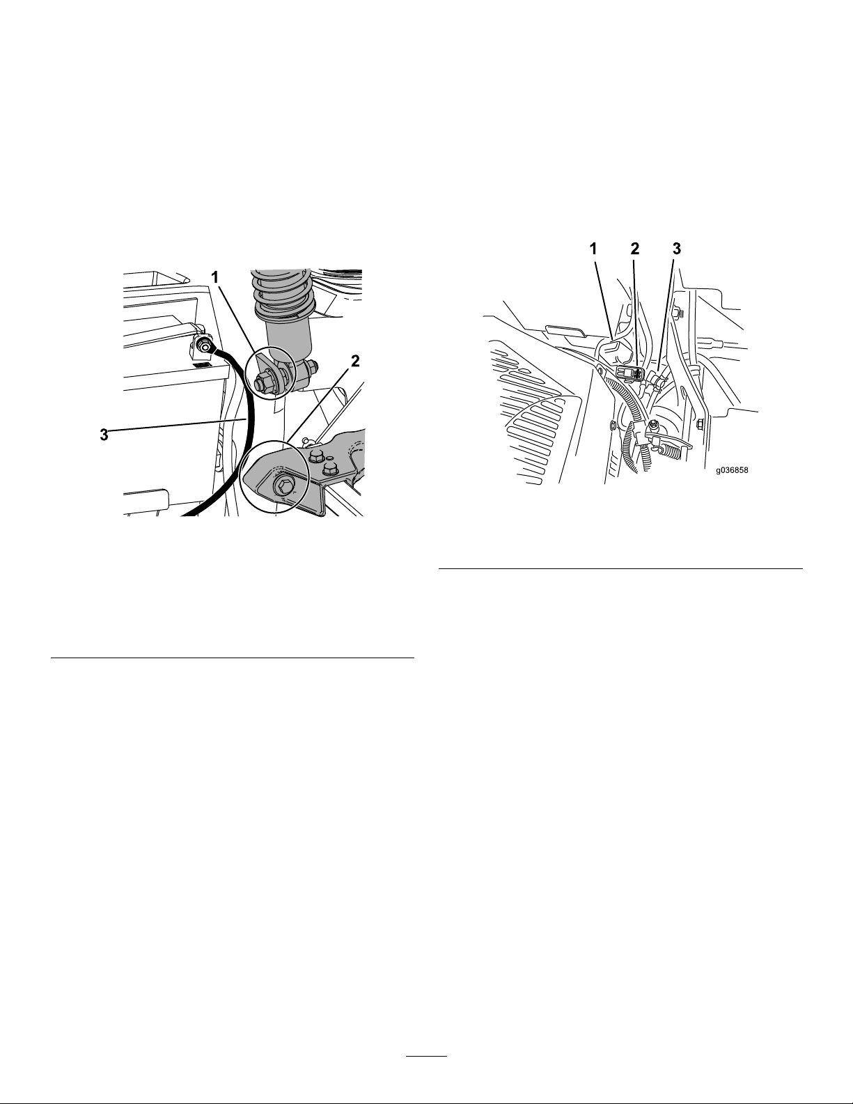
InstallingtheBattery
1.Positionthebatteryinthetraywiththeterminal
postsoppositefromthehydraulictank(Figure
81).
2.Installthepositive(red)batterycabletothe
positive(+)batteryterminal.
3.Installthenegative(black)batterycableand
groundwiretothenegative(-)batteryterminal.
Note:ForMyRidemachines,ensurethatthe
groundcabledoesnotrubagainstthetrailing
armorlowershockmount(Figure84).
ServicingtheFuses
Theelectricalsystemisprotectedbyfuses.Itrequires
nomaintenance;however,ifafuseblowscheckthe
componentandcircuitforamalfunctionorshort.
Thefusesarelocatedontherightconsolenexttothe
seat(Figure84).
1.T oreplacethefuses,pulloutthefusetoremove
it.
2.Installanewfuse(Figure84).
Figure83
1.Ensurethattheground
cabledoesnotrubagainst
thelowershockmount.
2.Ensurethattheground
cabledoesnotrubagainst
thetrailingarm.
3.Groundcable
4.Securethecableswith2bolts,2washers,and
2locknuts(Figure81).
5.Slidetheredterminalbootontothepositive(+)
batteryterminal.
6.Securethebatterywiththerubberstrap(Figure
81).
g036858
Figure84
g236732
1.Fusecover
2.Fuseholder
3.Fuel-shutoffvalve
60
Page 61

DriveSystem
Maintenance
CheckingtheSeatBelt
ServiceInterval:Beforeeachuseordaily
Inspecttheseatbeltforwear,cuts,andproper
operationoftheretractorandbuckle.Replacethe
seatbeltifitisdamaged.
CheckingtheRoll-Bar Knobs
ServiceInterval:Beforeeachuseordaily
WARNING
Toavoidinjuryordeathfromrollover,keep
therollbarinthefullyraised,lockedposition
andusetheseatbelt.
Ensurethattheseatissecuredtothe
machine.
•Checkthatboththemountinghardwareandthe
knobsareingoodworkingcondition.
•Makesurethattheknobsarefullyengagedwith
therollbarintheraisedposition.
Note:Theupperhoopoftherollbarmayneed
tobepushedforwardorpulledrearwardtofully
engagebothknobs(Figure85andFigure86).
1.Rollbarintheupright
position
2.Roll-barknobinthe
latchedposition
3.Pulltheroll-barknobout
androtateit90degrees.
g036746
Figure85
4.Rotatetheroll-barknob90
degrees.
5.Roll-barknobinthe
unlatchedposition
6.Rollbarinthefolded
position
g034593
Figure86
1.Engaged2.Partiallyengaged—donot
61
operatewiththerollbarin
thisposition.
Page 62

AdjustingtheTracking
CheckingtheTirePressure
1.Disengagetheblade-controlswitch(PTO).
2.Drivetoanopen,atareaandmovethe
motion-controlleverstotheNEUTRAL-LOCK
position.
3.MovethethrottlemidwaybetweentheFASTand
SLOWpositions.
4.Movebothmotion-controlleversforwarduntil
theybothhitthestopsintheT-slot.
5.Checkwhichwaythemachinetracks.
6.Ifthemachinetrackstotheright,inserta3/16
inchhexwrenchthroughtheaccessholeinthe
rightfrontcoverpanelandrotatethetracking
screwclockwiseorcounterclockwisetoadjust
thetravelofthelever(Figure87).
7.Ifthemachinetrackstotheleft,inserta3/16
inchhexwrenchthroughtheaccessholeinthe
rightfrontcoverpanelandrotatethetracking
screwclockwiseorcounterclockwisetoadjust
thetravelofthelever(Figure87).
8.Drivethemachineandcheckthefullforward
tracking.
9.Repeattheadjustmentuntilthedesiredtracking
isobtained.
ServiceInterval:Every50hours/Monthly(whichever
comesrst)
Maintaintheairpressureinthefrontandreartires
at90kPa(13psi).Uneventirepressurecancause
unevencut.Checkthetireswhentheyarecoldtoget
themostaccuratepressurereading.
g001055
Figure88
CheckingtheWheelLug Nuts
Rightcontrollevershown
1.Accessholeonfrontcover
panel
Checkandtorquethewheellugnutsto122to136
N∙m(90to100ft-lb).
g035859
Figure87
2.Trackingscrew
62
Page 63

CoolingSystem
Maintenance
BrakeMaintenance
AdjustingtheParking
CleaningtheEngineScreen
ServiceInterval:Beforeeachuseordaily
Beforeeachuseordaily
Beforeeachuseremoveanybuildupofgrass,dirt,or
otherdebrisfromtheenginescreen,engineexhaust,
andtheareaaroundtheengine.Thishelpsensure
adequatecoolingandcorrectenginespeedand
reducesthepossibilityofoverheatingandmechanical
damagetotheengine.
Brake
ServiceInterval:Every500hours
Note:Performthisprocedurewheneveryouremove
orreplaceabrakecomponent.
1.Parkthemachineonalevelsurface,disengage
theblade-controlswitch(PTO),andengagethe
parkingbrake.
2.Shutofftheengine,removethekey ,andwait
forallmovingpartstostopbeforeleavingthe
operatingposition.
3.Setupthemachinetobepushedbyhand.
RefertoUsingtheDrive-WheelReleaseValves
(page34).
4.Raisethebackofthemachineupandsupport
themachinewithjackstands.
WARNING
Relyingsolelyonmechanicalor
hydraulicjackstosupportaraised
machineforserviceormaintenance
couldbedangerousbecausethejacks
maynotprovideenoughsupportormay
malfunction,allowingthemachinetofall
andpossiblycauseseriousinjury.
Donotrelysolelyonmechanical
orhydraulicjacksforsupport.Use
adequatejackstandsorequivalent
support.
5.Engageanddisengagetheparkingbrakeand
checkeachdrivetiretoensurethateachbrake
engagesanddisengages.
6.Ifanadjustmentisnecessary ,disengagethe
parkingbrake.Removethecotterpinfromthe
brakelinkageshaft(Figure89).
63
Page 64

Figure89
1.Cotterpin3.Brakelinkageshaft
2.Parkingbrake
7.CheckbothspringlengthsasshowninFigure
90.Ifanadjustmentisnecessary,turnthe
topnutclockwisetoshortenthespringand
counterclockwisetolengthenit.
9.Rotatethebrake-linkageshaftuntiltheend
alignswiththeholeinthelever.
•Shortenthelinkagebyturningitclockwise.
•Lengthenthelinkagebyturningit
counterclockwise.
10.Insertthebrake-linkageshaftintothe
parking-brakeholeandsecurewiththecotter
pin.Repeatstep5andadjustifnecessary.
11.Whenadjustmentiscomplete,removethejack
standsorequivalentsupportandlowerthe
machine.
12.PlacethemachineintotheOPERATINGposition.
g036752
RefertoUsingtheDrive-WheelReleaseValves
(page34).
Figure90
1.T opnut
2.Spring
3.44mm(1-3/4inches)
8.Pushtheparkingbrakeleverallthewayforward
anddown.
g036100
64
Page 65

BeltMaintenance
InspectingtheBelts
ServiceInterval:Every50hours
Replacethebeltifitisworn.Thesignsofawornbelt
includesquealingwhilethebeltisrotating;theblades
slippingwhilecuttinggrass;andfrayededges,burn
marks,andcracksonthebelt.
ReplacingtheMowerBelt forSide-DischargeMower Decks
1.Parkthemachineonalevelsurface,disengage
theblade-controlswitch(PTO),andengagethe
parkingbrake.
2.Shutofftheengine,removethekey ,andwait
forallmovingpartstostopbeforeleavingthe
operatingposition.
3.Lowerthemowertothe76mm(3inch)height
ofcut.
4.Removethebeltcovers(Figure91).
Figure92
1500and2000SeriesMowerDecks
1.Clutchpulley3.Spring-loadedidlerpulley
2.Mowerbelt
4.Spring
g036861
Figure91
5.Removethespringtensionfromthe
spring-loadedidlerpulley.RefertoFigure93
orFigure94.
Note:For1500and2000Seriesmower
decks,usethespringremovaltool(T oroPart
No.92-5771)toremovethespringfromthe
mower-deckpost(Figure93).
Note:For2500Seriesmowerdecks,usea
ratchetinthesquareholeintheidlerarmto
removetensionontheidlerspring(Figure94).
6.Removethebeltfromthemower-deckpulleys
andtheclutchpulley.
7.Installthenewbeltaroundthemowerpulleys
andtheclutchpulleyundertheengine(Figure
92orFigure94).
g027729
g028279
Figure93
1500and2000SeriesMowerDecks
1.Spring-removaltool(Toro
PartNo.92-5771)
2.Idlerspring5.Mowerbelt
3.Mower-deckpost
65
4.Idlerarm
Page 66

ReplacingtheMowerBelt forRear-DischargeMower Decks
ReplacingtheCounter-Rotating Belt
1.Parkthemachineonalevelsurface,disengage
theblade-controlswitch(PTO),andengagethe
parkingbrake.
2.Shutofftheengine,removethekey ,andwait
forallmovingpartstostopbeforeleavingthe
operatingposition.
3.Lowerthemowertothe76mm(3inches)height
ofcut.
4.Lifttheoorpanuptogainaccesstothecenter
pulley.
Figure94
2500SeriesMowerDecks
1.Clutchpulley
2.Mowerbelt
3.Spring-loadedidlerpulley
4.Ratchet
5.Squareholeintheidler
armfortheratchet
8.Installtheidlerspring(Figure92orFigure94).
Note:Seatthespringendsintheanchor
grooves.
9.Installthebeltcovers(Figure95).
g036865
5.Removetheplasticbeltcover(Figure97).
6.Removethe3boltsholdingthemetalbeltcover
inplaceandremovethemetalbeltcover.
Figure95
g024145
Figure96
1.Idlerspring4.Idlerpulley
2.Counter-rotatingbelt5.Squareholeintheidler
3.Doublepulley
g027730
7.Usearatchetinthesquareholeintheidlerarm
armfortheratchet
toremovetensionontheidlerspring(Figure96).
8.Removethebeltfromthemowerdeckpulley
(Figure96).
66
Page 67

9.Removethebeltfromtheremainingpulleys
(Figure96).
10.Routethenewbeltaboundthemowerpulleys.
11.Usingtheratchetinthesquarehole,removethe
tensiononthespring,andguidethenewbelt
aroundtheidlerpulley(Figure96).
ReplacingtheMowerBelt
1.Parkthemachineonalevelsurface,disengage
theblade-controlswitch(PTO),andengagethe
parkingbrake.
2.Shutofftheengine,removethekey ,andwait
forallmovingpartstostopbeforeleavingthe
operatingposition.
3.Lowerthemowertothe76mm(3inches)height
ofcut.
Figure98
1.Mowerbelt
2.Spring-loadedidlerpulley4.Counter-rotatingbelt
3.Squareholeintheidler
armfortheratchet
g036863
4.Removethebeltcovers(Figure97).
Figure97
5.Removethecounter-rotatingbelt;referto
ReplacingtheCounter-RotatingBelt(page66).
6.Usearatchetinthesquareholeintheidlerarm
toremovetensionontheidlerspring(Figure98).
7.Removethebeltfromthemower-deckpulleys
andtheclutchpulley.
8.Installthenewbeltaroundthemowerpulleys
andtheclutchpulleyundertheengine(Figure
98).
9.Rotateandensurethebelt-guidetabhitsagainst
thepivothub(Figure98).
10.Usingtheratchetinthesquarehole,installthe
beltaroundthespring-loadedidlerpulley(Figure
98).Seatthespringendsintheanchorgrooves.
11.Installthecounter-rotatingbelt;referto
ReplacingtheCounter-RotatingBelt(page66).
g027729
12.Installthebeltcovers(Figure99).
g027730
Figure99
67
Page 68

ReplacingtheHydraulic Pump-DriveBelt
1.Parkthemachineonalevelsurface,disengage
theblade-controlswitch(PTO),andengagethe
parkingbrake.
2.Shutofftheengine,removethekey ,andwait
forallmovingpartstostopbeforeleavingthe
operatingposition.
3.Removethemowerbelt;refertoReplacingthe
MowerBeltforSide-DischargeMowerDecks
(page65)orReplacingtheMowerBeltfor
Rear-DischargeMowerDecks(page66).
4.Raisethemachineandsupportitwithjack
stands(Figure101).
5.Removetheclutchstop(Figure100).
Figure101
1.Idlerpulley4.Pump-drivebelt
2.Idler-springpost5.Righthydraulic-pump
3.Enginepulley
pulley
6.Lefthydraulic-pumppulley
9.Installtheclutchstop(Figure100).
g036859
Figure100
1.Clutchstop
6.Removetheidlerspringfromthepost(Figure
101).
7.Removetheexistingbeltfromthe
hydraulic-pump-drivepulleysandthe
enginepulley.
8.Installthenewbeltaroundtheenginepulleyand
the2hydraulic-pumppulleys(Figure101).
10.Installthemowerbelt;refertoBeltMaintenance
(page65).
g036860
68
Page 69

ControlsSystem
Maintenance
AdjustingtheTilt
1.Disengagetheblade-controlswitch(PTO),move
themotion-controlleverstotheNEUTRAL-LOCK
position,andengagetheparkingbrake.
Adjustingthe Control-HandlePosition
Iftheendsofthelevershitagainsteachother,referto
AdjustingtheMotion-ControlLinkage(page70).
AdjustingtheHeight
Youcanadjustthemotioncontrollevershigheror
lowerformaximumcomfort.
1.Disengagetheblade-controlswitch(PTO),move
themotion-controlleverstotheNEUTRAL-LOCK
position,andengagetheparkingbrake.
2.Shutofftheengine,removethekey ,andwait
forallmovingpartstostopbeforeleavingthe
operatingposition.
3.Removethehardwareholdingthecontrollever
tothecontrol-armshaft.
2.Shutofftheengine,removethekey ,andwait
forallmovingpartstostopbeforeleavingthe
operatingposition.
3.Loosentheupperboltholdingthecontrollever
tothecontrolarmshaft.
4.Loosenthelowerboltjustenoughtopivotthe
controlleverforeoraft.Tightenbothboltsto
securethecontrolinthenewposition.
5.Repeattheadjustmentfortheoppositecontrol
lever.
Figure102
1.Bolts
2.Slottedhole4.Control-armshaft
4.Movethecontrollevertothenextsetofholes.
Securetheleverwiththehardware.
5.Repeattheadjustmentfortheoppositecontrol
lever.
3.Controllever
g009195
Figure103
g035858
69
Page 70

Adjustingthe Motion-ControlLinkage
Locatedoneithersideofthemachine,belowtheseat,
arethepump-controllinkages.Rotatingtheendnut
witha1/2-inchdeepsocketwrenchallowsnetuning
adjustmentssothatthemachinedoesnotmovein
neutral.Anyadjustmentsshouldbemadeforneutral
positioningonly.
WARNING
Theenginemustberunningandthedrive
wheelsturningsothatyoucanperformthe
adjustments.Contactwithmovingpartsor
hotsurfacesmaycausepersonalinjury .
Keepyourngers,hands,andclothingclear
ofrotatingcomponentsandhotsurfaces.
1.Disengagetheblade-controlswitch(PTO),move
themotion-controlleverstotheNEUTRAL-LOCK
position,andengagetheparkingbrake.
2.Shutofftheengine,removethekey ,andwait
forallmovingpartstostopbeforeleavingthe
operatingposition.
11.Adjustthepump-control-rodlengthsbyturning
thenutintheappropriatedirectionuntilthe
wheelsslightlycreepinreverse(seeFigure
104).
12.Movethemotion-controlleverstotheREVERSE
positionandwhileapplyingslightpressureto
thelever,allowthereverseindicatorspringsto
bringtheleversbacktoneutral.
Note:Thewheelsshouldstopturningorslightly
creepinreverse.
Note:Y oumayneedtoremovethe
motion-controlcovertogainaccess.
3.Pushthedeck-liftpedalandremovethe
height-of-cutpin.Lowerthedecktotheground.
4.Raisetherearofthemachineupandsupportit
withjackstands(orequivalentsupport)justhigh
enoughtoallowthedrivewheelstoturnfreely.
5.Removetheelectricalconnectionfromtheseat
safetyswitch,locatedunderthebottomcushion
oftheseat.
Note:Theswitchisapartoftheseatassembly .
6.T emporarilyinstallajumperwireacrossthe
terminalsintheconnectorofthemainharness.
7.Starttheengine,runitatfullthrottle,and
disengagetheparkingbrake.
Note:Beforestartingtheengine,ensurethat
theparkingbrakeisengagedandthatthe
motion-controlleversareout.Youdonothave
tobeintheseat.
8.Runthemachineatleast5minuteswiththe
driveleversinthefullforwardspeedtobringthe
hydraulicuiduptooperatingtemperature.
Note:Themotion-controlleversmustbein
neutralwhileyouaremakinganyadjustments.
9.Bringthemotion-controlleversintotheNEUTRAL
position.
Figure104
1.Nut4.Return-to-neutralplate
2.Stationaryplate
3.Controlplate
13.Shutoffthemachine.
14.Removethejumperwirefromthewireharness
andplugtheconnectorintotheseatswitch.
15.Removethejackstands.
16.Raisethemowerdeckandinstallthe
height-of-cutpin.
17.Checkandensurethatthemachinedoes
notcreepinneutralwiththeparkingbrake
disengaged.
5.T abstouchingreturnto
neutralplate
g036753
10.Checkandensurethatthecontrol-platetabs
touchthereturn-to-neutralplatesonthe
hydraulicunits.
70
Page 71

HydraulicSystem
Maintenance
HydraulicSystemSafety
•Seekimmediatemedicalattentionifuidisinjected
intoskin.Injecteduidmustbesurgicallyremoved
withinafewhoursbyadoctor.
•Ensurethatallhydraulic-uidhosesandlinesare
ingoodconditionandallhydraulicconnections
andttingsaretightbeforeapplyingpressureto
thehydraulicsystem.
•Keepyourbodyandhandsawayfrompinhole
leaksornozzlesthatejecthigh-pressurehydraulic
uid.
g037051
Figure105
•Usecardboardorpapertondhydraulicleaks.
•Safelyrelieveallpressureinthehydraulicsystem
beforeperforminganyworkonthehydraulic
system.
ServicingtheHydraulic System
HydraulicFluidSpecications
HydraulicFluidType:Toro
hydraulicuid(preferred)orMobil115W-50oil.
®
HYPR-OIL
Important:Usetheuidspecied.Otheruids
couldcausesystemdamage.
HydraulicSystemCapacity(withltersremoved):
4.45L(150oz)
CheckingtheHydraulicFluidLevel
ServiceInterval:Beforeeachuseordaily
1.Allowthehydraulicuidtocooldown.Checkthe
oillevelwhentheuidiscold.
2.Checkexpansionreservoirandifnecessary
addT oro
FULLCOLDline.
®
HYPR-OIL
™
500hydraulicuidtothe
™
1.Engine2.Expansiontank
ChangingtheHydraulic-System FiltersandFluid
ServiceInterval:Aftertherst75hours—Changethe
hydraulic-systemltersanduid.
Every500hours—Aftertheinitial
change—changethehydraulic-system
ltersanduidwhenusingT oro
500
500uid(changeitmoreoftenundersevere
conditions).
Every250hours—Aftertheinitial
change—changethehydraulic-system
ltersanduidwhenusingMobil115W50uid
(changeitmoreoftenundersevereconditions).
Changetheltersanduidatthesametime.Do
notusetheuidagain.Purgeanyairinthesystem
afteryouinstallthenewltersandadduid.Referto
BleedingtheHydraulicSystem(page73).
Repeatthebleedingprocessuntiltheuidremains
attheFULLCOLDlineinthereservoirafterpurging.
Failuretoproperlyperformthisprocedurecan
resultinirreparabledamagetothetransaxledrive
system.
RemovingtheHydraulic-SystemFilters
®
HYPR-OIL
™
1.Parkthemachineonalevelsurface,disengage
theblade-controlswitch(PTO),andengagethe
parkingbrake.
2.Shutofftheengine,removethekey ,andwait
forallmovingpartstostopbeforeleavingthe
operatingposition.
3.Allowtheenginetocool.
71
Page 72

4.Locatethelterandguardsoneach
transaxle-drivesystem(Figure106).
5.Removethe3screwssecuringthelterguard
andguard(Figure106).
7.Slowlypourthespecieduidthroughthe
expansionreservoiruntiluidcomesoutof1
ofthevent-plugholes.
8.Installtheventplug.
9.T orquetheplugto20N∙m(15ft-lb).
10.Continuetoadduidthroughtheexpansion
reservoiruntiluidcomesoutoftheremaining
vent-plugholeonthesecondtransmission.
11.Installtheoppositeventplug.
12.T orquetheplugto20N∙m(15ft-lb).
13.Continuetoadduidthroughtheexpansion
reservoiruntilitreachestheFULLCOLDlineon
theexpansionreservoir.
14.ProceedtoBleedingtheHydraulicSystem
(page73).
Figure106
Rightsideshown
1.Transaxledrive
2.Filter
3.Filterguard
4.Screws
5.Ventplug
6.Carefullycleantheareaaroundthelters.
Important:Donotallowdirttoenterthe
hydraulicsystem,orcontaminationmay
occur.
7.Placeadrainpanbelowtheltertocatchthe
uidthatdrainswhenthelterandventplugs
areremoved.
8.Locateandremovetheventplugoneach
transmission.
9.Unscrewtheltertoremoveit,andallowthe
uidtodrainfromthedrivesystem.
10.Repeatthisprocedureforbothlters.
g017444
Important:FailuretoperformtheBleeding
theHydraulicSystemprocedureafter
changinghydraulicltersanduidcan
resultinirreparabledamagetothetransaxle
drivesystem.
InstallingtheHydraulic-SystemFilters
1.Applyathincoatofhydraulicuidonthesurface
oftherubbersealofeachlter.
2.Turnthelterclockwiseuntiltherubberseal
contactsthelteradapter,thentightenthelter
anadditional3/4to1fullturn.
3.Repeatfortheoppositelter.
4.Installthelterguardsovereachlterthatyou
previouslyremoved.
5.Usethe3screwstosecurethelterguards.
6.Verifythattheventplugsareremovedbefore
addingtheuid.
g027477
Figure107
72
Page 73

BleedingtheHydraulicSystem
1.Raisetherearofmachineandsupportitwith
jackstands(orequivalentsupport)justhigh
enoughtoallowthedrivewheelstoturnfreely.
Figure108
1.Jackingpoints
2.Starttheengine,movethethrottlecontrolahead
tothe1/2throttleposition,anddisengagethe
parkingbrake.
A.Movethebypassleversintothepushingthe
machineposition.Withthebypassvalves
openandtheenginerunning,slowlymove
themotion-controlleversinbothforward
andreverse5or6times.
B.Movethebypassleversintotheoperating
themachineposition.
C.Withthebypassvalveclosedandthe
enginerunning,slowlymovethecontrol
leverinbothforwardandreversedirections
5to6times.
D.Shutofftheengineandchecktheuid
levelintheexpansionreservoir.Addthe
specieduiduntilitreachestheFULLCOLD
lineontheexpansionreservoir.
3.Repeatstep2untilalltheairiscompletely
purgedfromthesystem.
Note:Whenthetransaxleoperatesatnormal
noiselevels,movessmoothlyforward,and
reversesatnormalspeeds,itispurged.
4.Checktheuidlevelintheexpansionreservoir
analtime.Addthespecieduidasuntilit
reachestheFULLCOLDlineontheexpansion
reservoir.
MowerDeck Maintenance
ServicingtheCutting Blades
Toensureasuperiorqualityofcut,keeptheblades
sharp.Forconvenientsharpeningandreplacement,
keepextrabladesonhand.
BladeSafety
Awornordamagedbladecanbreak,andapieceof
thebladecouldbethrowntowardyouorbystanders,
resultinginseriouspersonalinjuryordeath.Tryingto
g017625
repairadamagedblademayresultindiscontinued
safetycerticationoftheproduct.
•Inspectthebladesperiodicallyforwearordamage.
•Usecarewhencheckingtheblades.Wrapthe
bladesorweargloves,andusecautionwhen
servicingtheblades.Onlyreplaceorsharpenthe
blades;neverstraightenorweldthem.
•Onmulti-bladedmachines,takecareasrotating1
bladecancauseotherbladestorotate.
BeforeInspectingorServicingthe Blades
1.Parkthemachineonalevelsurface,disengage
theblade-controlswitch(PTO),andengagethe
parkingbrake.
2.Shutofftheengine,removethekey,and
disconnectthespark-plugwiresfromthespark
plugs.
InspectingtheBlades
ServiceInterval:Beforeeachuseordaily
1.Inspectthecuttingedges(Figure109).
2.Iftheedgesarenotsharporhavenicks,remove
andsharpentheblade;refertoSharpeningthe
Blades(page76).
3.Inspecttheblades,especiallyinthecurvedarea.
4.Ifyounoticeanycracks,wear,oraslotforming
inthisarea,immediatelyinstallanewblade
(Figure109).
73
Page 74

Figure109
g006530
1.Cuttingedge3.Wear/slotforming
2.Curvedarea4.Crack
CheckingforBentBlades
Note:Themachinemustbeonalevelsurfacefor
thefollowingprocedure.
1.Raisethemowerdecktothehighest
height-of-cutposition.
2.Whilewearingthicklypaddedgloves,orother
adequatehandprotection,slowlyrotatethe
bladeintoapositionthatallowsyoutomeasure
thedistancebetweenthecuttingedgeandthe
levelsurfacethemachineison(Figure110).
Figure110
1.Deck3.Blade
2.Spindlehousing
3.Measurefromthetipofthebladetotheat
surface(Figure111).
g014973
Figure111
1.Blade(inpositionformeasuring)
2.Levelsurface
3.Measureddistancebetweenbladeandthesurface(A)
4.Rotatethesameblade180degreessothat
theopposingcuttingedgeisnowinthesame
position(Figure112).
g014974
Figure112
1.Blade(sidepreviouslymeasured)
2.Measurement(positionusedpreviously)
3.Opposingsideofbladebeingmovedintomeasurement
g014972
position
5.Measurefromthetipofthebladetotheat
surface(Figure113).
Note:Thevarianceshouldbenomorethan
3mm(1/8inch).
74
Page 75

Figure113
1.Oppositebladeedge(inpositionformeasuring)
2.Levelsurface
3.Secondmeasureddistancebetweenbladeandsurface(B)
g014973
A.IfthedifferencebetweenAandBisgreater
than3mm(1/8inch),replacethebladewith
anewblade;refertoReplacingtheBlades
forSideDischargeMowerDecks(page75)
orReplacingtheBladesforRearDischarge
MowerDecks(page75).
Note:Ifabentbladeisreplacedwitha
newblade,andthedimensionobtained
continuestoexceed3mm(1/8inch),the
bladespindlecouldbebent.Contactan
AuthorizedServiceDealerforservice.
B.Ifthevarianceiswithinconstraints,moveto
thenextblade.
6.Repeatthisprocedureoneachblade.
ReplacingtheBladesforSide DischargeMowerDecks
RemovingtheBladesforSide-Discharge
MowerDeck
Figure114
1.Sailareaoftheblade
2.Blade
3.Curvedwasher
4.Bladebolt
5.Spindleshaft
InstallingtheBladesforSideDischarge
MowerDecks
1.Installthebladeontothespindleshaft(Figure
114).
Important:Thecurvedpartoftheblade
mustpointupwardtowardtheinsideofthe
mowertoensurepropercutting.
2.Installthecurvedwasherandbladebolt(Figure
114).
Note:Installthecurved-washerconetoward
thebolthead.
3.T orquethebladeboltto115to150N∙m(85to
110ft-lb).
g017443
Replacethebladesiftheyhitasolidobject,orifthe
bladeisoutofbalanceorbent.
1.Holdthespindleshaftwithawrench.
2.Removethebladebolt,curvedwasher,and
bladefromthespindleshaft(Figure114).
ReplacingtheBladesforRear DischargeMowerDecks
RemovingtheBladesforRearDischarge
MowerDecks
Replacethebladesiftheyhitasolidobject,areout
ofbalance,orbent.
1.Holdthebladeendusingaragorathickly
paddedglove.
2.Removetheleftandcenterbladebolt,curved
washer,andbladefromthespindleshaft(Figure
115).
75
Page 76

3.Removetherightbladebolt(left-handthreaded
bolt),curvedwasher,andbladefromthespindle
shaft(Figure116).
Note:Notethebladetypeandwhereeach
bladeisinstalled.SeeFigure116forthecorrect
position.
Figure115
LeftandCenterSpindleShown
1.Sailareaoftheblade
2.Blade
3.Curvedwasher
4.Bladebolt
5.Spindleshaft
g024248
Figure116
g017443
1.Frontofmowerdeck4.Counter-rotatingblade
2.Right-handthreadedblade
bolts
3.Regularblades
5.Left-handthreadedblade
bolt
InstallingtheBladesforRearDischarge
MowerDecks
Important:Therightbladeonthismower
deckiscounter-rotatingandusesaleft-hand
threadedbladebolt.UseFigure116forthecorrect
placementofthemowerblades.
1.Installtheleftandcenterblades,curved
washers,andbladeboltstothespindleshafts
(Figure115andFigure1 16).
Note:Ensurethecurvedpartofthebladeis
pointingupwardtowardtheinsideofthemower
decktoensurepropercutting.
Note:Ensurethecurved-washerconeis
installedtowardthebolthead(Figure115).
2.Installtherightblade,curvedwasher,andblade
bolt(left-handthreadedbolt)tothespindleshaft
(Figure115andFigure1 16).
3.T orquethebladeboltsto115to150N∙m(85to
110ft-lb);refertoFigure116.
SharpeningtheBlades
1.Usealetosharpenthecuttingedgeatboth
endsoftheblade(Figure117).
Note:Maintaintheoriginalangle.
Note:Thebladeretainsitsbalanceifthesame
amountofmaterialisremovedfrombothcutting
edges.
g000552
Figure117
1.Sharpenatoriginalangle.
2.Checkthebalanceofthebladebyputtingiton
abladebalancer(Figure1 18).
Note:Ifthebladestaysinahorizontalposition,
thebladeisbalancedandcanbeused.
76
Page 77

Note:Ifthebladeisnotbalanced,lesome
metalofftheendofthesailareaonly(Figure
117).
Figure118
1.Blade2.Balancer
g000553
3.Repeatthisprocedureuntilthebladeis
balanced.
LevelingtheMowerDeck
Checktoensurethatthemowerdeckislevelanytime
youinstallthemowerorwhenyouseeanunevencut
onyourlawn.
Checkthemowerdeckforbentbladespriorto
leveling,andremoveandreplaceanybentblades;
refertotheServicingtheCuttingBlades(page73)
beforecontinuing.
Levelthemowerdeckside-to-siderst;thenyoucan
adjustthefront-to-rearslope.
Requirements:
•Themachinemustbeonalevelsurface.
•Alltiresmustbeproperlyinated;refertoChecking
theTirePressure(page62).
AdjustingtheSide-to-Side LevelingandtheBladeSlope
Figure119
1.Bladessidetoside
2.Bladetip
3.Measurefromthetipofthe
bladetotheatsurface
here.
7.Checkthefront-to-rearbladelevel(Figure120).
Ensurethefrontbladetipislowerthantherear
bladetipasshownintheblockheightandrake
table.Ifitneedsadjustment,continuewiththis
procedure.
g229303
g229305
1.Parkthemachineonalevelsurface,disengage
theblade-controlswitch(PTO),andengagethe
parkingbrake.
2.Shutofftheengine,removethekey ,andwait
forallmovingpartstostopbeforeleavingthe
operatingposition.
3.Checkthetirepressureinthedrivetires.Refer
toCheckingtheTirePressure(page62).
4.Positionthemowerdeckinthetransport-lock
position.
5.Carefullyrotatethebladesfromsidetoside.
6.Measurebetweenthebladetipandtheat
surface(Figure1 19).Ifthemeasurementsare
notwithin5mm(3/16inch),adjusttheleveling;
continuewiththisprocedure.
g229304
Figure120
1.Bladesfronttorear3.Measurefromthetipofthe
bladetotheatsurface
here.
2.Bladetip
77
Page 78

8.Settheanti-scalprollerstotopholesorremove
themcompletelyforthisadjustment.
9.Place2blocks(seetablebelow)undertherear
edgeofthecuttingdeckskirt;1oneachsideof
thecuttingdeck(Figure121).
10.Settheheight-of-cutlevertothe3inch(76mm)
position.
11.Place2blocksundereachsideofthefrontedge
ofthedeck,butnotundertheanti-scalproller
bracketsorwelds.
Figure121
Bottomview
g035851
Figure122
1.Locknuts3.Deckhanger
2.Deck-liftarm4.Chain
16.Ensurethattheblockstsnuglyunderthedeck
g038090
skirtandthatallattachmentboltsaretight
17.Continuelevelingthedeckbycheckingthe
front-to-rearbladeslope.
1.Block—7.3cm(2.87
inches)
2.Welds
BlockHeightandRakeTable
DeckSize
Allmower
decks
12.Carefullyrotatethebladessidetoside(Figure
119).
13.Loosenthelocknuts(Figure122)onall4
cornersandensurethatthemowerdeckis
sittingsecurelyonall4blocks.
14.Removeanyslackfromthedeckhangersand
makesurethedeck-liftfootleverispushedback
againstthestop.
15.Tightenthe4locknuts.
BlockHeightRake
7.3cm(2.87inches)4.8to6.4mm(3/16to1/4
inch)
18.Checkthebladesforlevelnessandrepeatdeck
levelingprocedureifnecessary.
78
Page 79

RemovingtheMowerDeck
1.Parkthemachineonalevelsurface,disengage
theblade-controlswitch(PTO),andengagethe
parkingbrake.
2.Shutofftheengine,removethekey ,andwait
forallmovingpartstostopbeforeleavingthe
operatingposition.
3.Lowertheheight-of-cutlevertothelowest
position.
4.Removethehairpincotterfromthefrontsupport
rod,andremovetherodfromthedeckbracket
(Figure123).
g005077
Figure124
Figure123
1.Frontsupportrod3.Deckbracket
2.Lockingnut
5.Carefullylowerthefrontofthemowerdeckto
theground.
6.Liftthemowerdeckandhangerbracketsclear
oftherearliftrodandlowerthemowercarefully
totheground(Figure124).
1.Mowerdeck
2.Hangerbracket
7.Slidethemowerdeckrearwardtoremovethe
mowerbeltfromtheenginepulley.
8.Slidethemowerdeckoutfromunderneaththe
machine.
3.Rearliftrod
Note:Retainallpartsforfutureinstallation.
ReplacingtheGrass
Deector
Side-DischargeMachinesOnly
g005076
WARNING
Anuncovereddischargeopeningcouldallow
themachinetothrowobjectstowardyouor
bystanders,resultinginseriousinjury.Also,
contactwiththebladecouldoccur.
Neveroperatethemachineunlessyouinstall
amulchplate,dischargedeector,orgrass
collectionsystem.
1.Removethelocknut,bolt,spring,andspacer
holdingthedeectortothepivotbrackets
(Figure125).
2.Removethedamagedorworngrassdeector
(Figure125).
79
Page 80

Figure125
1.Bolt
2.Spacer6.Grassdeector
3.Locknut
4.Spring
5.Springinstalled
7.J-hookendofspring
Cleaning
CleaningundertheMower Deck
ServiceInterval:Beforeeachuseordaily
1.Parkthemachineonalevelsurface,disengage
theblade-controlswitch(PTO),andengagethe
parkingbrake.
2.Shutofftheengine,removethekey ,andwait
g015594
forallmovingpartstostopbeforeleavingthe
operatingposition.
3.RaisethemowerdecktotheTRANSPORT
position.
CleaningtheSuspension
3.Placethespacerandthespringontograss
deector.
4.Place1J-hookendofthespringbehindthe
deckedge.
Note:Makesurethat1J-hookendofthe
springisinstalledbehindthedeckedgebefore
installingtheboltasshowninFigure125.
5.Installtheboltandthenut.
6.Place1J-hookendofthespringaroundthe
grassdeector(Figure125).
Important:Thegrassdeectormustbeable
torotate.Liftthedeectoruptothefullopen
positionandensurethatitrotatesintothe
fulldownposition.
System
ServiceInterval:Beforeeachuseordaily
Usecompressedairtocleanthesuspensionsystem.
Note:Donotcleantheshockassemblieswith
pressurizedwater(Figure126).
g195820
Figure126
DisposingofWaste
Engineoil,batteries,hydraulicuid,andengine
coolantarepollutantstotheenvironment.Disposeof
theseaccordingtoyourstateandlocalregulations.
80
Page 81

Storage
StorageSafety
•Shutofftheengine,removethekey ,waitforall
movingpartstostop,andallowthemachineto
coolbeforestoringit.
•Donotstorethemachineorfuelnearamesor
drainthefuelindoors.
•Removethekeyandstoreitinasafeplaceout
ofthereachofchildren.
CleaningandStorage
1.Disengagetheblade-controlswitch(PTO),and
engagetheparkingbrake.
2.Shutofftheengine,removethekey ,andwait
forallmovingpartstostopbeforeleavingthe
operatingposition.
12.Checktheconditionoftheblades;referto
ServicingtheCuttingBlades(page73).
13.Preparethemachineforstoragewhennon-use
occursover30days.Preparethemachinefor
storageasfollows:
A.Addapetroleum-based
stabilizer/conditionertofuelinthe
tank.Followmixinginstructionsfrom
thestabilizermanufacturer.Donotuse
analcohol-basedstabilizer(ethanolor
methanol).
Note:Afuelstabilizer/conditionerismost
effectivewhenmixedwithfreshfueland
usedatalltimes.
B.Runtheenginetodistributeconditionedfuel
throughthefuelsystemfor5minutes.
C.Shutofftheengine,allowittocool,and
drainthefueltank.
D.Starttheengineandrunituntilitstops.
3.Removegrassclippings,dirt,andgrimefromthe
externalpartsoftheentiremachine,especially
theengineandhydraulicsystem.Cleandirtand
chafffromtheoutsideoftheenginecylinder
headnsandblowerhousing.
Important:Youcanwashthemachinewith
milddetergentandwater.Donotpressure
washthemachine.Avoidexcessiveuse
ofwater,especiallynearthecontrolpanel,
engine,hydraulicpumps,andmotors.
4.Checktheparkingbrakeoperation;referto
AdjustingtheParkingBrake(page63).
5.Servicetheaircleaner;refertoEngine
Maintenance(page41).
6.Greasethemachine;refertoLubrication(page
39).
7.Changethecrankcaseoil;refertoEngine
Maintenance(page41).
8.Checkthetirepressure;refertoCheckingthe
TirePressure(page62).
9.Changethehydrauliclters;refertoChanging
theHydraulic-SystemFiltersandFluid(page
71).
E.Disposeoffuelproperly.Recyclethefuel
accordingtolocalcodes.
Important:Donotstorefuelcontaining
stabilizer/conditionerlongerthan
thedurationrecommendedbythe
fuel-stabilizermanufacturer.
14.Removeandchecktheconditionofthespark
plug(s);refertoEngineMaintenance(page41).
Withthesparkplug(s)removedfromtheengine,
pour30ml(2tablespoons)ofengineoilintothe
sparkplughole.Usethestartertocrankthe
engineanddistributetheoilinsidethecylinder.
Installthesparkplug(s).Donotinstallthewire
onthesparkplug(s).
15.Checkandtightenallbolts,nuts,andscrews.
Repairorreplaceanypartthatisdamaged.
16.Paintallscratchedorbaremetalsurfaces.Paint
isavailablefromyourAuthorizedServiceDealer.
17.Storethemachineinaclean,drygarageor
storagearea.Removethekeyfromtheswitch
andkeepitoutofreachofchildrenorother
unauthorizedusers.Coverthemachineto
protectitandkeepitclean.
10.Chargethebattery;refertoChargingtheBattery
(page59).
11.Scrapeanyheavybuildupofgrassanddirt
fromtheundersideofthemower,thenwashthe
mowerwithagardenhose.
Note:Runthemachinewiththeblade-control
switch(PTO)engagedandtheengineathigh
idlefor2to5minutesafterwashing.
81
Page 82

Troubleshooting
Problem
Theengineoverheats.
Thestarterdoesnotcrank.
Theenginedoesnotstart,startshard,or
failstokeeprunning.
PossibleCauseCorrectiveAction
1.Theengineloadisexcessive.1.Reducethegroundspeed.
2.Theoillevelinthecrankcaseislow.2.Addoiltothecrankcase.
3.Thecoolingnsandairpassages
undertheengine-blowerhousingare
plugged.
4.Theaircleanerisdirty.
5.Dirt,water,orstalefuelisinthefuel
system.
1.Theblade-controlswitchisengaged.1.Disengagetheblade-controlswitch.
2.Themotion-controlleversarenotin
theNEUTRAL-LOCKposition.
3.Thebatteryisdead.
4.Theelectricalconnectionsare
corrodedorloose.
5.Afuseisblown.5.Replacethefuse.
6.Arelayorswitchisdamaged.
1.Thefueltankisempty.1.Fillthefueltank.
2.Thefuel-shutoffvalveisclosed.2.Openthefuel-shutoffvalve.
3.Theoillevelinthecrankcaseislow.3.Addoiltothecrankcase.
4.Thethrottleisnotinthecorrect
position.
5.Thereisdirtinthefuellter.5.Replacethefuellter.
6.Dirt,water,orstalefuelisinfuel
system.
7.Theaircleanerisdirty.
8.Theseatswitchisnotfunctioning
properly.
9.Theelectricalconnectionsare
corroded,loose,ordamaged.
10.Therelayorswitchiswornor
damaged.
11.Thesparkplugisfouledorimproperly
gapped.
12.Thespark-plugwireisnotconnected.
3.Removetheobstructionfromthe
coolingnsandairpassages.
4.Cleanorreplacetheair-cleaner
element.
5.ContactanAuthorizedServiceDealer
2.Movethemotion-controllevers
outwardtotheNEUTRAL-LOCKposition.
3.Chargethebattery.
4.Checktheelectricalconnectionsfor
goodcontact.
6.ContactanAuthorizedServiceDealer.
4.Besurethatthethrottlecontrolis
midwaybetweentheslowandfast
positions.
6.ContactanAuthorizedServiceDealer.
7.Cleanorreplacetheair-cleaner
element.
8.Checktheseat-switchindicator .
Replacetheseatifnecessary .
9.Checktheelectricalconnections
forgoodcontact.Cleanthe
connectorterminalsthoroughlywith
electrical-contactcleaner,apply
dielectricgrease,andmakethe
appropriateconnections.
10.ContactanAuthorizedServiceDealer.
11.Adjustorreplacethesparkplug.
12.Checkthespark-plugwireconnection.
Theenginelosespower.
Themowerpullstotheleftorright(with
leversfullyforward)
1.Theengineloadisexcessive.1.Reducethegroundspeed.
2.Theaircleanerisdirty.
3.Theoillevelinthecrankcaseislow.3.Addoiltothecrankcase.
4.Thecoolingnsandtheairpassages
abovetheengineareplugged.
5.
Theventholeinthefuelcapisplugged.
6.Thereisdirtinthefuellter.6.Replacethefuellter.
7.Thereisdirt,water,orstalefuelinthe
fuelsystem.
1.Thetrackingneedsadjustment1.Adjustthetracking.
2.Thetirepressureinthedrivetiresis
notcorrect.
2.Cleantheair-cleanerelement.
4.Removetheobstructionfromthe
coolingnsandtheairpassages.
5.
Cleanorreplacethefuelcap.
7.ContactanAuthorizedServiceDealer.
2.Adjustthetirepressureinthedrive
tires.
82
Page 83

Problem
PossibleCauseCorrectiveAction
Themachinedoesnotdrive.
Themachinevibratesabnormally .
Thecuttingheightisuneven.
1.Thebypassvalvesarenotclosedtight.1.Tightenthebypassvalves.
2.Thepumpbeltisworn,loose,or
broken.
3.Thepumpbeltisoffapulley .3.Changethebelt.
4.Theidlerspringisbrokenormissing.4.Replacethespring.
5.Thehydraulicuidlevelislowortoo
hot.
1.Thecuttingblade(s)is/arebentor
unbalanced.
2.Theblademountingboltisloose.2.Tightentheblademountingbolt.
3.Theenginemountingboltsareloose.3.Tightentheenginemountingbolts.
4.Theenginepulley ,idlerpulley,orblade
pulleyisloose.
5.Theenginepulleyisdamaged.
6.Thebladespindleisbent.
7.Themotormountislooseorworn.
1.Theblade(s)isnotsharp.1.Sharpentheblade(s).
2.Acuttingblade(s)is/arebent.2.Installanewcuttingblade(s).
3.Themowerisnotlevel.
4.Ananti-scalproller(ifapplicable)isnot
setcorrectly .
5.Theundersideofthemowerdeckis
dirty.
6.Thetirepressureisincorrect.6.Adjustthetirepressure.
7.Abladespindleisbent.
2.Changethebelt.
5.Addhydraulicuidtothereservoirsor
letitcooldown.
1.Installnewcuttingblade(s).
4.Tightentheappropriatepulley.
5.ContactanAuthorizedServiceDealer.
6.ContactanAuthorizedServiceDealer.
7.ContactanAuthorizedServiceDealer.
3.Levelthemowerfromside-to-sideand
front-to-rear.
4.Adjusttheanti-scalpwheelheight.
5.Cleantheundersideofthemower
deck.
7.ContactanAuthorizedServiceDealer.
Thebladesdonotrotate.
Theclutchdoesnotengage.
1.Thedrivebeltisworn,looseorbroken.1.Installanewdrivebelt.
2.Thedrivebeltisoffofthepulley .
3.Thepowertakeoff(PTO)switchor
PTOclutchisfaulty.
4.Themowerbeltisworn,loose,or
broken.
1.Thefuseisblown.
2.Thereislowvoltagesupplyatthe
clutch.
3.Thecoilisdamaged.3.Replacetheclutch.
4.Thereisinadequatecurrentsupply.4.Repairorreplacetheclutchlead
5.
Therotor/armatureairgapistoolarge.
2.Installthedrivebeltandcheckthe
adjustingshaftsandbeltguidesforthe
correctposition.
3.ContactanAuthorizedServiceDealer.
4.Installanewmowerbelt.
1.Replacethefuse.Checkthecoil
resistance,batterycharge,charging
system,andwiringconnections,and
replacecomponentsifnecessary.
2.Checkthecoilresistance,battery
charge,chargingsystem,andwiring
connectionsandreplacepartsif
necessary.
wireorelectricalsystem.Cleanthe
connectorcontacts.
5.Removetheshimorreplacetheclutch.
83
Page 84

Schematics
WireDiagram—ToroEngines(Rev.A)
84
g018479
Page 85

WireDiagram—KohlerEngines(Rev.A)
85
g036151
Page 86

WireDiagram—KawasakiEngines(Rev.A)
86
g037072
Page 87

CaliforniaProposition65WarningInformation
Whatisthiswarning?
Youmayseeaproductforsalethathasawarninglabellikethefollowing:
WARNING:CancerandReproductiveHarm—www.p65Warnings.ca.gov.
WhatisProp65?
Prop65appliestoanycompanyoperatinginCalifornia,sellingproductsinCalifornia,ormanufacturingproductsthatmaybesoldinorbroughtinto
California.ItmandatesthattheGovernorofCaliforniamaintainandpublishalistofchemicalsknowntocausecancer,birthdefects,and/orother
reproductiveharm.Thelist,whichisupdatedannually,includeshundredsofchemicalsfoundinmanyeverydayitems.ThepurposeofProp65isto
informthepublicaboutexposuretothesechemicals.
Prop65doesnotbanthesaleofproductscontainingthesechemicalsbutinsteadrequireswarningsonanyproduct,productpackaging,orliteraturewith
theproduct.Moreover,aProp65warningdoesnotmeanthataproductisinviolationofanyproductsafetystandardsorrequirements.Infact,the
CaliforniagovernmenthasclariedthataProp65warning“isnotthesameasaregulatorydecisionthataproductis‘safe’or‘unsafe.’”Manyofthese
chemicalshavebeenusedineverydayproductsforyearswithoutdocumentedharm.Formoreinformation,gotohttps://oag.ca.gov/prop65/faqs-view-all
AProp65warningmeansthatacompanyhaseither(1)evaluatedtheexposureandhasconcludedthatitexceedsthe“nosignicantrisklevel”;or(2)
haschosentoprovideawarningbasedonitsunderstandingaboutthepresenceofalistedchemicalwithoutattemptingtoevaluatetheexposure.
Doesthislawapplyeverywhere?
Prop65warningsarerequiredunderCalifornialawonly.ThesewarningsareseenthroughoutCaliforniainawiderangeofsettings,includingbutnot
limitedtorestaurants,grocerystores,hotels,schools,andhospitals,andonawidevarietyofproducts.Additionally,someonlineandmailorder
retailersprovideProp65warningsontheirwebsitesorincatalogs.
.
HowdotheCaliforniawarningscomparetofederallimits?
Prop65standardsareoftenmorestringentthanfederalandinternationalstandards.TherearevarioussubstancesthatrequireaProp65warning
atlevelsthatarefarlowerthanfederalactionlimits.Forexample,theProp65standardforwarningsforleadis0.5μg/day,whichiswellbelow
thefederalandinternationalstandards.
Whydon’tallsimilarproductscarrythewarning?
•ProductssoldinCaliforniarequireProp65labellingwhilesimilarproductssoldelsewheredonot.
•AcompanyinvolvedinaProp65lawsuitreachingasettlementmayberequiredtouseProp65warningsforitsproducts,butothercompanies
makingsimilarproductsmayhavenosuchrequirement.
•TheenforcementofProp65isinconsistent.
•CompaniesmayelectnottoprovidewarningsbecausetheyconcludethattheyarenotrequiredtodosounderProp65;alackofwarningsfora
productdoesnotmeanthattheproductisfreeoflistedchemicalsatsimilarlevels.
WhydoesToroincludethiswarning?
Torohaschosentoprovideconsumerswithasmuchinformationaspossiblesothattheycanmakeinformeddecisionsabouttheproductstheybuyand
use.T oroprovideswarningsincertaincasesbasedonitsknowledgeofthepresenceofoneormorelistedchemicalswithoutevaluatingthelevelof
exposure,asnotallthelistedchemicalsprovideexposurelimitrequirements.WhiletheexposurefromToroproductsmaybenegligibleorwellwithinthe
“nosignicantrisk”range,outofanabundanceofcaution,TorohaselectedtoprovidetheProp65warnings.Moreover ,ifT orodoesnotprovidethese
warnings,itcouldbesuedbytheStateofCaliforniaorbyprivatepartiesseekingtoenforceProp65andsubjecttosubstantialpenalties.
RevA
Page 88

 Loading...