

Page 1

TITAN
ModelNo.Allmodels
®
HDSeriesRidingMowers
Setup
LooseParts
Usethechartbelowtoverifythatallpartshavebeenshipped.
FormNo.3407-539RevA
SetupInstructions
ProcedureDescription
1
2
3
4
5
6
7
8
9
10
Nopartsrequired
Nopartsrequired
Nopartsrequired
Nopartsrequired
Nopartsrequired
Nopartsrequired
Nopartsrequired
Nopartsrequired
No.2lithiumormolybdenum-based
grease(purchaseseparately)
Locknut(3/8inch)
Carriagebolt(3/8x2-1/4inches)
1tube
Qty.
Use
–
–
–
–
–
–
–
–
3
3
Removethemachinefromthecrate.
Addfueltothemachine.
Checktheengine-oillevel.
Servicethehydraulicoil.
Checkthetirepressure.
Servicingthebattery.
Raisetherolloverprotectionsystem
(ROPS).
Checkthegrassdeector.
Checkthemachineforgrease.
Installtherightbumper(reardischarge
modelsonly).
11
12
13
Note:Determinetheleftandrightsidesofthemachinefromthenormaloperatingposition.
©2016—TheT oro®Company
8111LyndaleAvenueSouth
Bloomington,MN55420
Nopartsrequired
Nopartsrequired
Operator'sManual
Engineowner'smanual(non-Toro
engines)
Operator-trainingmaterial
Key2
Registrationcard1
Registeratwww.T oro.com.
–
–
1
1
1
Checkthemoweradjustment.
Checkthemachinebeforedeliveryto
thecustomer(allmachines).
Deliverthemachinetothecustomer(all
machines).
OriginalInstructions(EN)
PrintedintheUSA
AllRightsReserved
*3407-539*A
Page 2
1
4
RemovingtheMachinefrom
theCrate
NoPartsRequired
Procedure
Ifremovingthemachinefromametalcrate,refertothe
Dealer/DistributorPortalforfurtherinformation.
2
AddingFueltotheMachine
NoPartsRequired
Procedure
Addfueltothemachinebeforestartingit.Refertoyour
Operator’sManualforthecorrectfuelandprocedure.
ServicingtheHydraulicOil
NoPartsRequired
Procedure
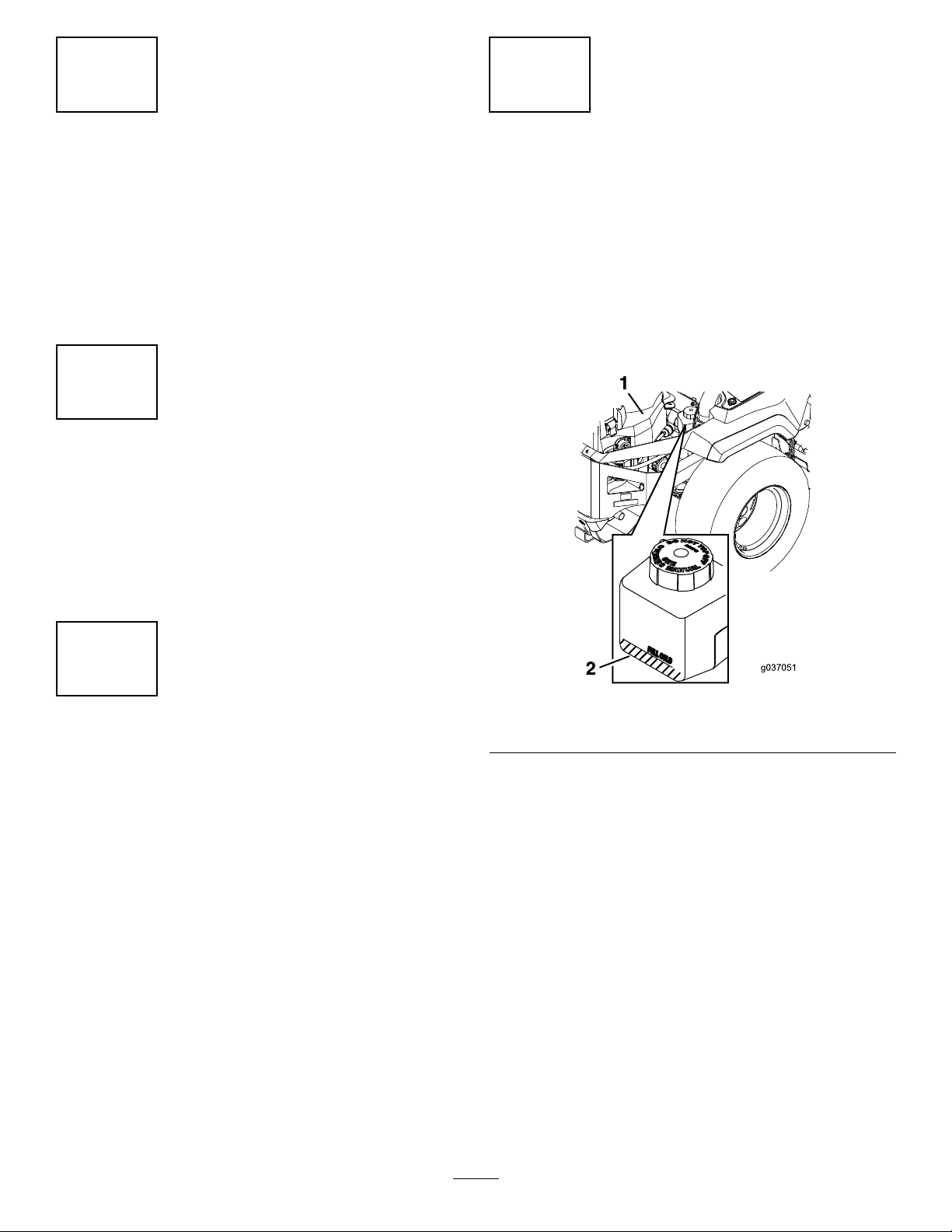
Thismachineisshippedlledwithhydraulicuidinthe
reservoirs.
Checktheexpansiontank;ifnecessary,addToro
HYPR-OIL
Operator'sManual,totheFULLCOLDline(Figure1).
™
500hydraulicuid,asrecommendedinthe
®
3
CheckingtheEngine-OilLevel
NoPartsRequired
Procedure
Beforeyoustarttheengineandusethemachine,check
theoillevelintheenginecrankcase;refertoServicingthe
Engine-OilLevelintheOperator'sManual.
Figure1
1.Engine2.Expansiontank
2
Page 3
5
CheckingtheTirePressure
NoPartsRequired
Procedure
Pressure:13psi(90kPa)
Note:Checkthetirepressurebeforestartingthemachine.
RefertoyourOperator’ sManualforthecorrecttiretypeand
procedure.
6
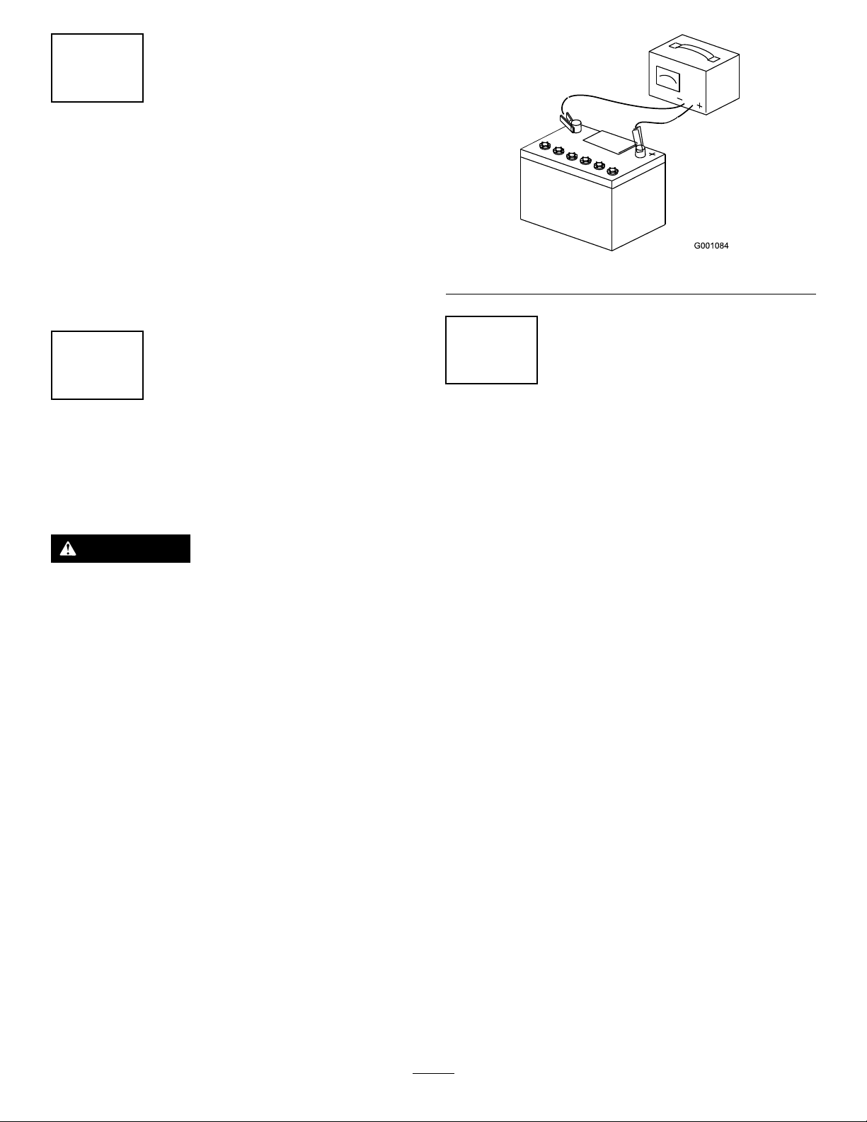
ServicingtheBattery
Figure2
7
RaisingtheRollover
ProtectionSystem(ROPS)
NoPartsRequired
Procedure
WARNING
Chargingthebatteryproducesgassesthatcan
explodeandcauseseriousinjury.
•Keepcigarettes,sparks,andamesawayfrom
thebattery.
•Makesurethattheignitionswitchisoff.
•Ventilatewhenchargingorusingthebatteryin
anenclosedspace.
Important:Donotrunthemachinewiththebattery
disconnected;electricaldamagemayoccurtothe
engine.
1.Chargethebattery.RefertotheOperator'sManualfor
instructions.
2.Connectthenegativebatterycable.
NoPartsRequired
Procedure
1.Pullbothknobsoutandrotatethem90degreessothat
theyarenotengaged(Figure3).
2.Raisetherollbartotheoperatingpositionandrotate
theknobsuntiltheymovepartiallyintothegrooves
(Figure3).
Note:Ifthepositivecableisalsodisconnected,
connectthepositive(red)cabletothepositivebattery
terminalrst,thenthenegative(black)cabletothe
negativebatteryterminal.Slipinsulatorbootoverthe
positiveterminal.
3
Page 4

1.Rollbarintheuprightposition
1
2
3
2
4
G021 181
4
3
3
2.ROPSknobinthelatchedposition
3.PulltheROPSknobout.
4.RotatetheROPSknob90degrees.
5.ROPSknobintheunlatchedposition
Figure3
8
CheckingtheGrassDeector
NoPartsRequired
Procedure
Ifthereareplastictiesholdingthegrassdeectorup,remove
themandlowerthedeectorintoplace.
WARNING
Anuncovereddischargeopeningcouldallowthe
machinetothrowobjectsintheoperator'sor
bystander'sdirectionandresultinseriousinjuryor
death.Also,contactwiththebladecouldoccur.
Neveroperatethemachinewithoutacoverplate,a
mulchplate,grassdeector,orbaggerinstalled.
1.Makesurethatoneendofthespringisinstalledbehind
thedeckedgebeforeinstallingtheboltasshownin
Figure4.
2.Placetheotherendofthespringaroundgrassdeector
(Figure4).
Important:Thegrassdeectormustbefreeto
rotatewithdownwardtension.Liftthedeectorup
tothefullopenpositionandensurethatitrotates
freely,withoutbindingintothefulldownposition.
3.Raisetherollbartothefulluprightpositionwhile
pushingontheupperrollbarsothatthepinssnapinto
positionwhentheholesalignwiththepins.
4.Pushontherollbarandensurethatbothpinsare
engaged(Figure3).
Figure4
1.Grassdeector3.Endofspring
2.Spring
4.Deckedge
4
Page 5

9
10
CheckingtheMachinefor
Grease
Partsneededforthisprocedure:
1tube
Procedure
Beforeyouusethemachine,checkthemachineforgrease;
refertoLubricationintheOperator'sManual.
No.2lithiumormolybdenum-basedgrease(purchase
separately)
InstallingtheRightBumper
Partsneededforthisprocedure:
3
Locknut(3/8inch)
3
Carriagebolt(3/8x2-1/4inches)
Procedure
Mountthesidebumpersinthetopholeswhenoperatingin
heightofcuthigherthan64mm(2-1/2inches)andinthe
centerholeswhenoperatinginheightofcutlowerthan64
mm(2-1/2inches).
1.Raisethemowerdecktothe12.7cm(5inch)height
position(alsothetransportposition).
2.Therightbumperisziptiedtothemachinefor
shipping.Removeanddiscardtheplasticzipties.
Figure5
1.Carriagebolt
2.Bumper(center-holemountingshown)
3.Locknut
3.Moveeachbumpertothedesiredpositionandsecure
itwith3carriagebolts(3/8x2-1/4inches)and3
locknuts(3/8inch).
4.Torquetheboltsto14to16N∙m(10to12ft-lb).
5
Page 6

11
CheckingtheMower
Adjustment
NoPartsRequired
Procedure
Adjusttheside-to-sidelevelandthefront-to-rearbladeslope.
UsetherelevantproceduresintheOperator'sManualtoverify
thatthedeckislevel,andmakeanyadjustmentsasnecessary.
6
Page 7

12
CheckingtheMachineBeforeDeliverytotheCustomer(All
Machines)
NoPartsRequired
Procedure
Beforedeliveringthemachinetothecustomer,ensurethatyouhaveperformedtheprocedureslistedinthefollowingtableand
initialeachwhennished.RefertotheOperator'sManualforinstructionsonperformingtheseprocedures.
Initial
Checkthetirepressure.
Checkthelevelofthemowerdeck.
Checktheengine-oillevel.
Checkthehydraulic-uidlevel.
CheckthattheROPSissecure.
Checktheadjustmentoftheparkingbrake.
Ensurethatthemachinetrackscorrectly;refertotheOperator'sManualfortheadjustmentprocedure.
Checkthesafetyinterlocksystem;refertotheOperator'sManual.
EnsurethatthePTOworks.
Checkallfastenersthatyouinstalledtoensurethattheyaretight.
Whenyounishsettingupthemachine,signanddateinthespaceprovidedbelow:
Signature:
CheckProcedure
Date:
13
DeliveringtheMachinetotheCustomer(AllMachines)
Partsneededforthisprocedure:
1
Operator'sManual
1
Engineowner'smanual(non-T oroengines)
1
Operator-trainingmaterial
2Key
1Registrationcard
Procedure
Atdelivery,llinthemodelandserialnumber,completetheitemslistedinthefollowingtable,andinitialeachwhennished.
ModelNo.SerialNo.
7
Page 8

DealerInitial
CustomerInitialCheckProcedure
Showthecustomerwherethefollowingfeaturesarelocatedandhowtheyfunction:
•
Fueltank
•
Oil-llcap/Oildipstick
•
Sparkplug(s)
•
Engine-oillter
•
Engine-oildrain
•
Fuelgauge,valve,andhose
•
Airlter
•
Hydraulic-uidreservoir
•
Hydrauliclter
•
Battery
•
Ignitionswitch
•
Throttlelever
•
Choke(ifapplicable)
•
Powertakeoffswitch(PTO)
•
Motion-controllevers
•
Parkingbrake
•
Heightofcut
•
Lift-assistlever(ifapplicable)
•
Adjustableseat
•
Hydraulic-bypassvalves
•
RolloverProtectionSystem(ROPS)
RefertotheOperator'sManualtopointoutsafetyprocedures,operation,and
maintenanceprocedures.
ReviewthewarrantystatementasshownintheOperator'sManual.
Describethepost-saleserviceproceduresforyourstore.
Assistthecustomerinllingoutandmailingtheregistrationcardorregisteronline
atwww.Toro.com.
MakesurethatthecustomerreceivestheOperator'sManual,engineowner'smanual
(non-Toroengines),SetUpInstructions,andoperatortrainingmaterial.
MakesurethecustomerknowsthatthePartsCatalogisavailableatwww .Toro.com.
Assistthecustomerinloadingthemachine.
Note:Whenyou,thedealerrepresentative,havenisheddeliveringthemachinetothecustomer,signanddateinthespace
providebelowandkeepacopyofthispagefordealerrecords.Also,thedealermustremindthecustomertouseafull-width
trailerramptoloadthemachine.
Signature:
Signature:Date:
Date:
8
 Loading...