

Page 1
FormNo.3414-620RevB
122cmTITAN
®
HD1500Series
RidingMower
ModelNo.74447TE—SerialNo.400000000andUp
ModelNo.74451TE—SerialNo.400000000andUp
Registeratwww.T oro.com.
OriginalInstructions(EN)
*3414-620*B
Page 2
ThisproductcomplieswithallrelevantEuropean
directives;fordetails,pleaseseetheseparateproduct
specicDeclarationofConformity(DOC)sheet.
ThissparkignitionsystemcomplieswithCanadian
ICES-002.
WARNING
Removingstandardoriginalequipmentparts
andaccessoriesmayalterthewarranty,
traction,andsafetyofthemachine.Failureto
useoriginalToropartscouldcauseserious
injuryordeath.Makingunauthorizedchanges
totheengine,fuelorventingsystem,may
violateregulations.
Replaceallpartsincluding,butnotlimited
to,tires,belts,blades,andfuelsystem
componentswithoriginalToroparts.
Important:IfyouareusingamachinewithaT oro
engineabove1500m(5,000ft)foracontinuous
period,ensurethattheHighAltitudeKithasbeen
installedsothattheenginemeetsCARB/EPA
emissionregulations.TheHighAltitudeKit
increasesengineperformancewhilepreventing
spark-plugfouling,hardstarting,andincreased
emissions.Onceyouhaveinstalledthekit,attach
thehigh-altitudelabelnexttotheserialdecalon
themachine.ContactanyAuthorizedT oroService
DealertoobtaintheproperHighAltitudeKitand
high-altitudelabelforyourmachine.Tolocate
adealerconvenienttoyou,accessourwebsite
atwww.T oro.comorcontactourToroCustomer
CareDepartmentatthenumber(s)listedinyour
EmissionControlWarrantyStatement.
Removethekitfromtheengineandrestorethe
enginetoitsoriginalfactorycongurationwhen
runningtheengineunder1500m(5,000ft).Do
notoperateanenginethathasbeenconverted
forhigh-altitudeuseatloweraltitudes;otherwise,
youcouldoverheatanddamagetheengine.
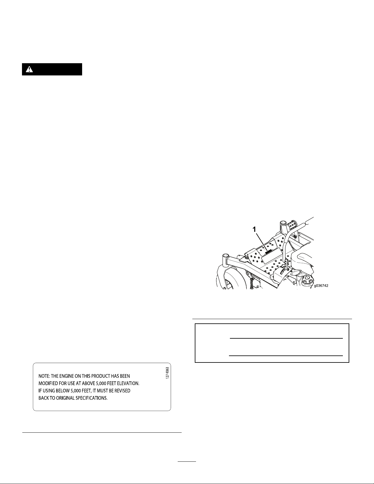
Ifyouareunsurewhetherornotyourmachinehas
beenconvertedforhigh-altitudeuse,lookforthe
followinglabel(Figure3).
Introduction
Thisrotary-blade,ridinglawnmowerisintendedtobe
usedbyresidentialhomeownersorprofessional,hired
operators.Itisdesignedprimarilyforcuttinggrasson
well-maintainedlawnsonresidentialorcommercial
properties.Itisnotdesignedforcuttingbrushorfor
agriculturaluses.
Readthisinformationcarefullytolearnhowtooperate
andmaintainyourproductproperlyandtoavoid
injuryandproductdamage.Youareresponsiblefor
operatingtheproductproperlyandsafely.
YoumaycontactT orodirectlyatwww.T oro.com
forproductsafetyandoperationtrainingmaterials,
accessoryinformation,helpndingadealer,orto
registeryourproduct.
Wheneveryouneedservice,genuineT oroparts,or
additionalinformation,contactanAuthorizedService
DealerorToroCustomerServiceandhavethemodel
andserialnumbersofyourproductready.Figure1
identiesthelocationofthemodelandserialnumbers
ontheproduct.Writethenumbersinthespace
provided.
g036742
Figure1
1.Modelandserialnumberlocation
ModelNo.
SerialNo.
©2018—TheToro®Company
8111LyndaleAvenueSouth
Bloomington,MN55420
Figure3
decal127-9363
Contactusatwww.Toro.com.
2
PrintedintheUSA
AllRightsReserved
Page 3

Thismanualidentiespotentialhazardsandhas
safetymessagesidentiedbythesafety-alertsymbol
(Figure2),whichsignalsahazardthatmaycause
seriousinjuryordeathifyoudonotfollowthe
recommendedprecautions.
Figure2
1.Safety-alertsymbol
Thismanualuses2wordstohighlightinformation.
Importantcallsattentiontospecialmechanical
informationandNoteemphasizesgeneralinformation
worthyofspecialattention.
Contents
Safety.......................................................................4
GeneralSafety...................................................4
SlopeIndicator...................................................5
SafetyandInstructionalDecals..........................6
ProductOverview...................................................12
g000502
Controls...........................................................12
Specications..................................................14
BeforeOperation.................................................14
BeforeOperationSafety...................................14
RecommendedFuel.........................................15
UsingStabilizer/Conditioner.............................15
FillingtheFuelTank..........................................15
CheckingtheEngine-OilLevel..........................16
BreakinginaNewMachine..............................16
UsingtheRollover-ProtectionSystem
(ROPS).........................................................16
ThinkSafetyFirst..............................................17
UsingtheSafety-InterlockSystem....................18
PositioningtheSeat..........................................19
ChangingtheSeatSuspension.........................19
UsingAttachmentsandAccessories.................19
DuringOperation.................................................19
DuringOperationSafety...................................19
OperatingtheParkingBrake.............................20
OperatingtheMowerBlade-ControlSwitch
(PTO)............................................................21
OperatingtheThrottle.......................................21
OperatingtheChoke.........................................21
OperatingtheIgnitionSwitch............................22
StartingandShuttingOfftheEngine.................22
UsingtheMotion-ControlLevers.......................24
DrivingtheMachine..........................................24
AdjustingtheHeight-of-Cut...............................26
AdjustingtheAnti-ScalpRollers........................26
StoppingtheMachine.......................................27
UsingtheSideDischarge.................................27
OperatingTips.................................................27
AfterOperation....................................................28
AfterOperationSafety......................................28
UsingtheFuel-ShutoffValve.............................28
UsingtheDrive-Wheel-ReleaseV alves............29
TransportingtheMachine.................................30
LoadingtheMachine........................................30
Maintenance...........................................................32
RecommendedMaintenanceSchedule(s)...........32
Pre-MaintenanceProcedures..............................33
MaintenanceandStorage.................................33
ReleasingtheMower-DeckCurtain..................33
RemovingtheSheet-MetalGuard.....................33
Lubrication..........................................................35
GreasingtheMachine.......................................35
EngineMaintenance...........................................36
EngineSafety...................................................36
ServicingtheEngine.........................................36
CheckingtheSparkArrester.............................41
3
Page 4

ReplacingtheEmissions-AirIntake
Filter..............................................................41
FuelSystemMaintenance...................................41
ReplacingtheFuelFilter...................................41
ServicingtheFuelT ank.....................................42
ElectricalSystemMaintenance...........................42
ElectricalSystemSafety...................................42
ServicingtheBattery.........................................42
ServicingtheFuses..........................................44
DriveSystemMaintenance..................................45
CheckingtheSeatBelt.....................................45
CheckingtheRoll-BarKnobs............................45
AdjustingtheTracking......................................46
CheckingtheTirePressure...............................46
CheckingtheWheelLugNuts...........................46
CoolingSystemMaintenance..............................47
CleaningtheEngineScreen.............................47
BrakeMaintenance.............................................47
AdjustingtheParkingBrake..............................47
BeltMaintenance................................................49
InspectingtheBelts..........................................49
ReplacingtheMowerBeltforSideDischarge
MowerDecks................................................49
ReplacingtheHydraulic-Pump-Drive
Belt................................................................50
ControlsSystemMaintenance.............................51
AdjustingtheControl-HandlePosition..............51
AdjustingtheMotion-ControlLinkage...............51
HydraulicSystemMaintenance...........................53
HydraulicSystemSafety...................................53
ServicingtheHydraulicSystem........................53
ChangingtheHydraulic-SystemFiltersand
Fluid..............................................................54
MowerDeckMaintenance....................................57
LevelingtheMowerDeck..................................57
ServicingtheCuttingBlades.............................58
RemovingtheMowerDeck...............................61
ReplacingtheGrassDeector..........................61
Cleaning..............................................................62
CleaningundertheMower................................62
DisposingofWaste...........................................62
Storage...................................................................62
CleaningandStoringtheMachine....................62
Troubleshooting......................................................64
Schematics.............................................................66
Safety
Thismachinehasbeendesignedinaccordancewith
ENISO5395:2013.
GeneralSafety
Thisproductiscapableofamputatinghandsand
feetandofthrowingobjects.Alwaysfollowallsafety
instructionstoavoidseriouspersonalinjury .
Usingthisproductforpurposesotherthanitsintended
usecouldprovedangeroustoyouandbystanders.
•Readandunderstandthecontentsofthis
Operator’sManualbeforeyoustarttheengine.
Ensurethateveryoneusingthisproductknows
howtouseitandunderstandsthewarnings.
•Donotputyourhandsorfeetnearmoving
componentsofthemachine.
•Donotoperatethemachinewithoutallguards
andothersafetyprotectivedevicesinplaceand
workingonthemachine.
•Keepclearofanydischargeopening.Keep
bystandersasafedistancefromthemachine.
•Keepchildrenoutoftheoperatingarea.Never
allowchildrentooperatethemachine.
•Stopthemachineandshutofftheenginebefore
servicing,fueling,oruncloggingthemachine.
Improperlyusingormaintainingthismachinecan
resultininjury .Toreducethepotentialforinjury ,
complywiththesesafetyinstructionsandalwayspay
attentiontothesafety-alertsymbol,whichmeans
Caution,Warning,orDanger—personalsafety
instruction.Failuretocomplywiththeseinstructions
mayresultinpersonalinjuryordeath.
Youcanndadditionalitemsofsafetyinformationin
theirrespectivesectionsthroughoutthismanual.
4
Page 5
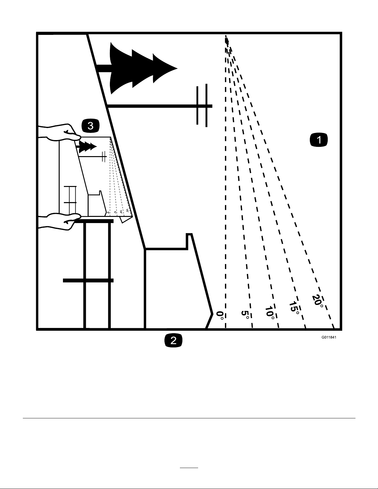
SlopeIndicator
Figure4
Thispagemaybecopiedforpersonaluse.
1.Themaximumslopeyoucansafelyoperatethemachineonis15degrees.Usetheslopecharttodeterminethedegreeofslope
ofhillsbeforeoperating.Donotoperatethismachineonaslopegreaterthan15degrees.Foldalongtheappropriateline
tomatchtherecommendedslope.
2.Alignthisedgewithaverticalsurface,atree,building,fencepole,etc.
3.Exampleofhowtocompareslopewithfoldededge.
5
g011841
Page 6
SafetyandInstructionalDecals
Safetydecalsandinstructionsareeasilyvisibletotheoperatorandarelocatednearanyarea
ofpotentialdanger.Replaceanydecalthatisdamagedorlost.
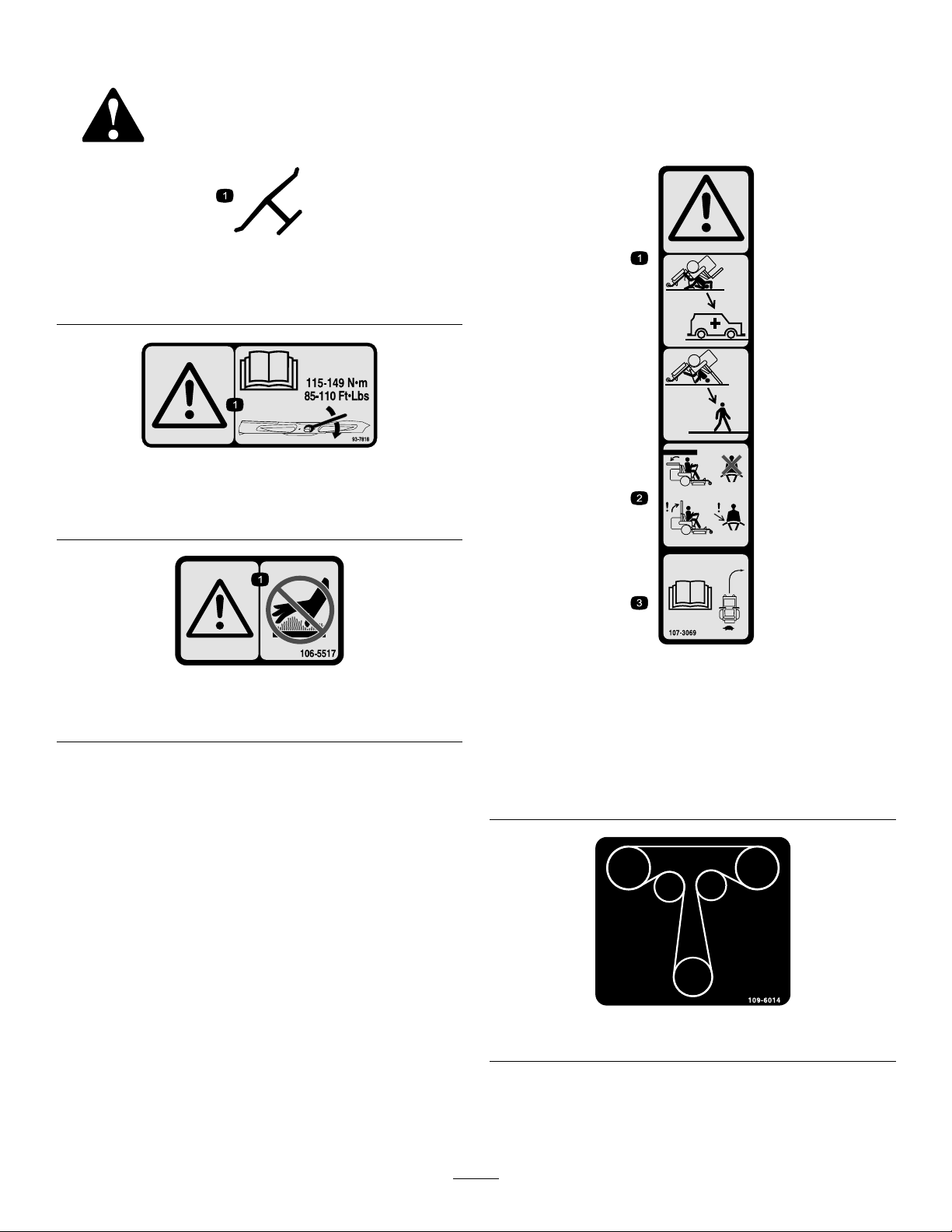
Manufacturer'sMark
1.Indicatesthebladeisidentiedasapartfromtheoriginal
machinemanufacturer.
93-7818
1.Warning—readtheOperator'sManualforinstructionson
torquingthebladebolt/nutto115-149N∙m(85-110ft-lb).
decaloemmarkt
decal93-7818
1.Warning—donottouchthehotsurface.
decal107-3069
decal106-5517
106-5517
1.Warning–thereisnorolloverprotectionwhentherollbaris
down.
2.Toavoidinjuryordeathfromarolloveraccident,keepthe
rollbarintheraisedandlockedpositionandweartheseat
belt.Lowertherollbaronlywhenabsolutelynecessary;do
notweartheseatbeltwhentherollbarisdown.
3.ReadtheOperator'sManual;driveslowlyandcarefully .
107-3069
decal109-6014
109-6014
6
Page 7
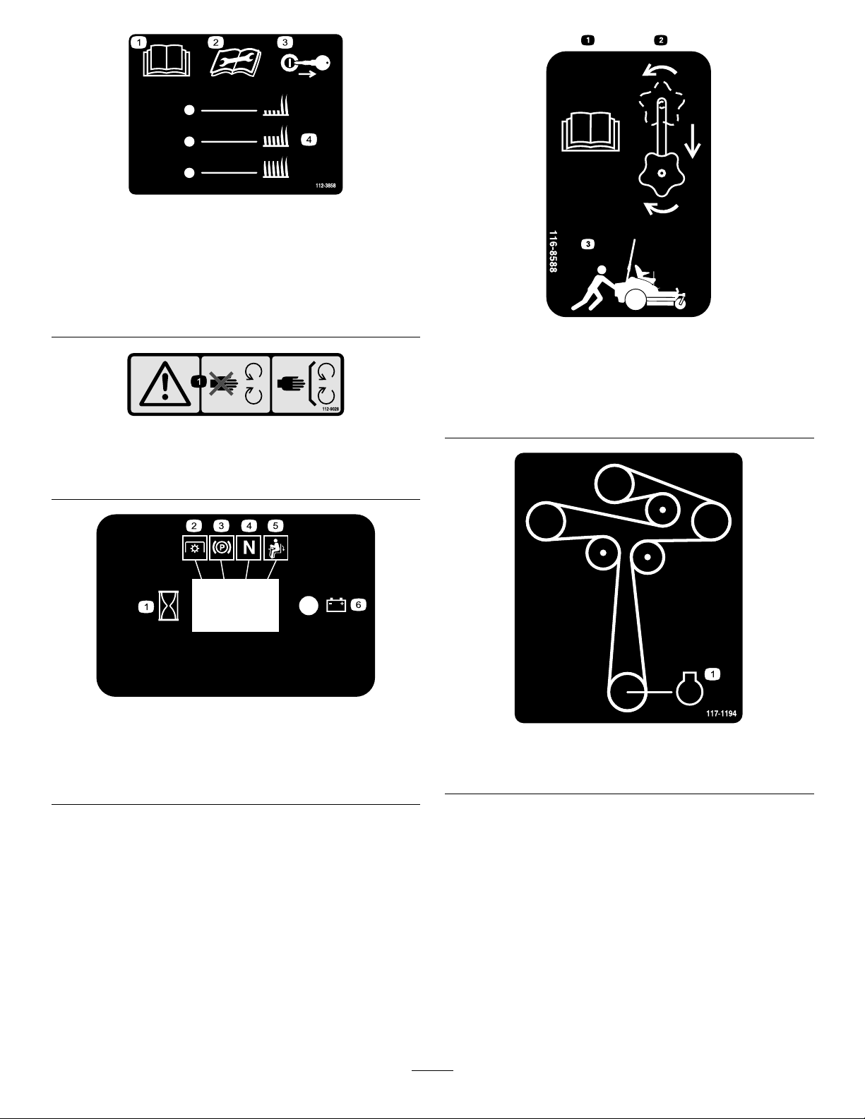
decal112-3858
112-3858
1.ReadtheOperator's
Manual.
3.Removetheignitionkey
beforeadjustingtheheight
ofcut.
2.Readtheinstructions
4.Height-of-cutsettings.
beforeservicingor
performingmaintenance.
decal112-9028
112-9028
1.Warning—stayawayfrommovingparts;keepallguardsin
place.
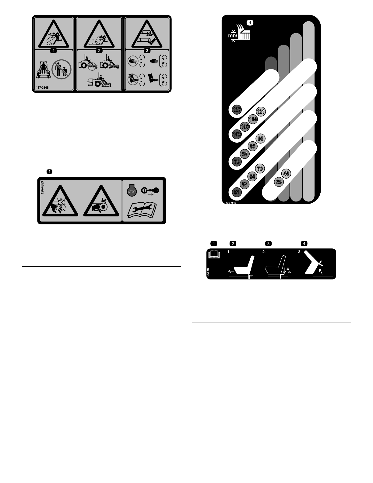
decal116-8588
116-8588
1.ReadtheOperator’smanual.
2.Rotatethedrivereleaseknobtoloosen,slidetheknob,
andtighten.
3.Pushthemachine.
decalhourmessagedisplay-116-5610
MessageDisplay
1.Hour4.Neutral
2.PTO5.Operatorpresenceswitch
3.Parkingbrake6.Battery
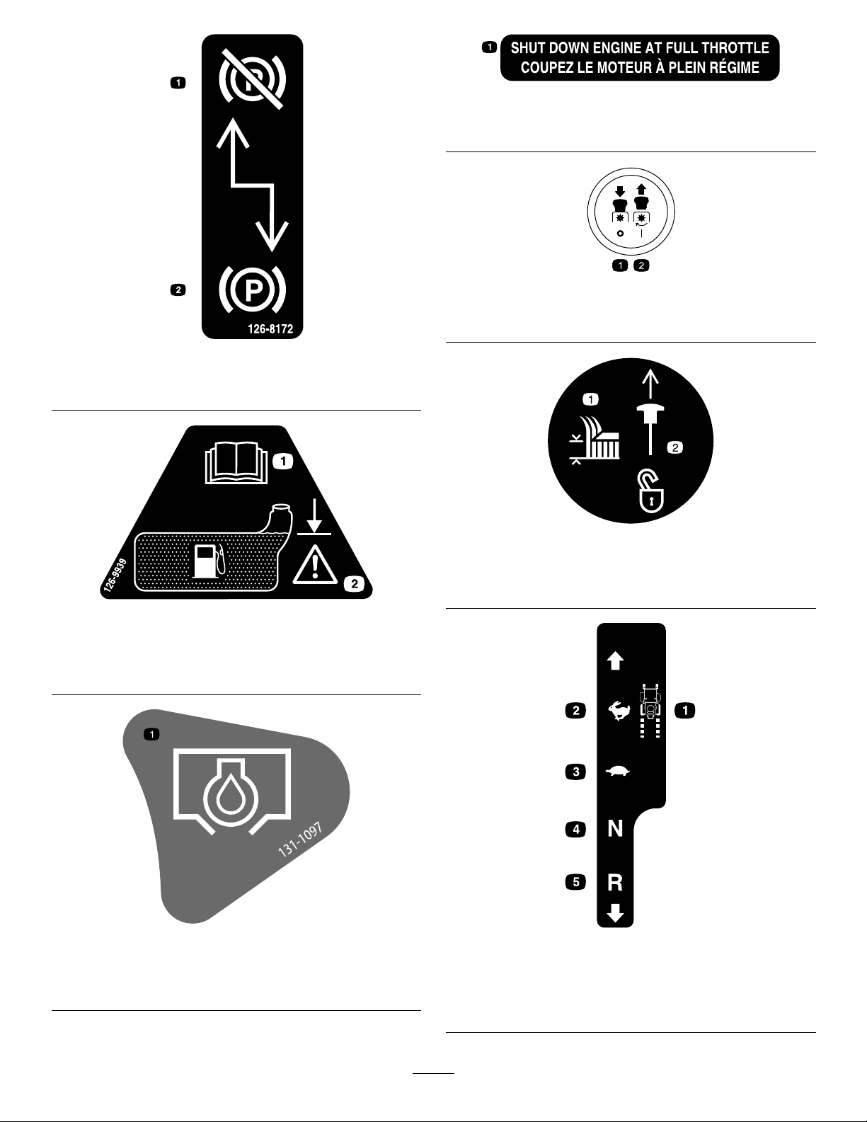
decal117-1 194
117-1194
1.Engine
7
Page 8
117-3848
1.Thrownobjecthazard—keepbystandersasafedistance
fromthemachine.
2.Thrownobjecthazard,mower—donotoperatethemachine
withoutdeector,dischargecover,orgrasscollection
systeminplace.
3.Cutting/dismembermentofhandorfoot—stayawayfrom
movingparts;keepallguardsandshieldsinplace.
decal117-3848
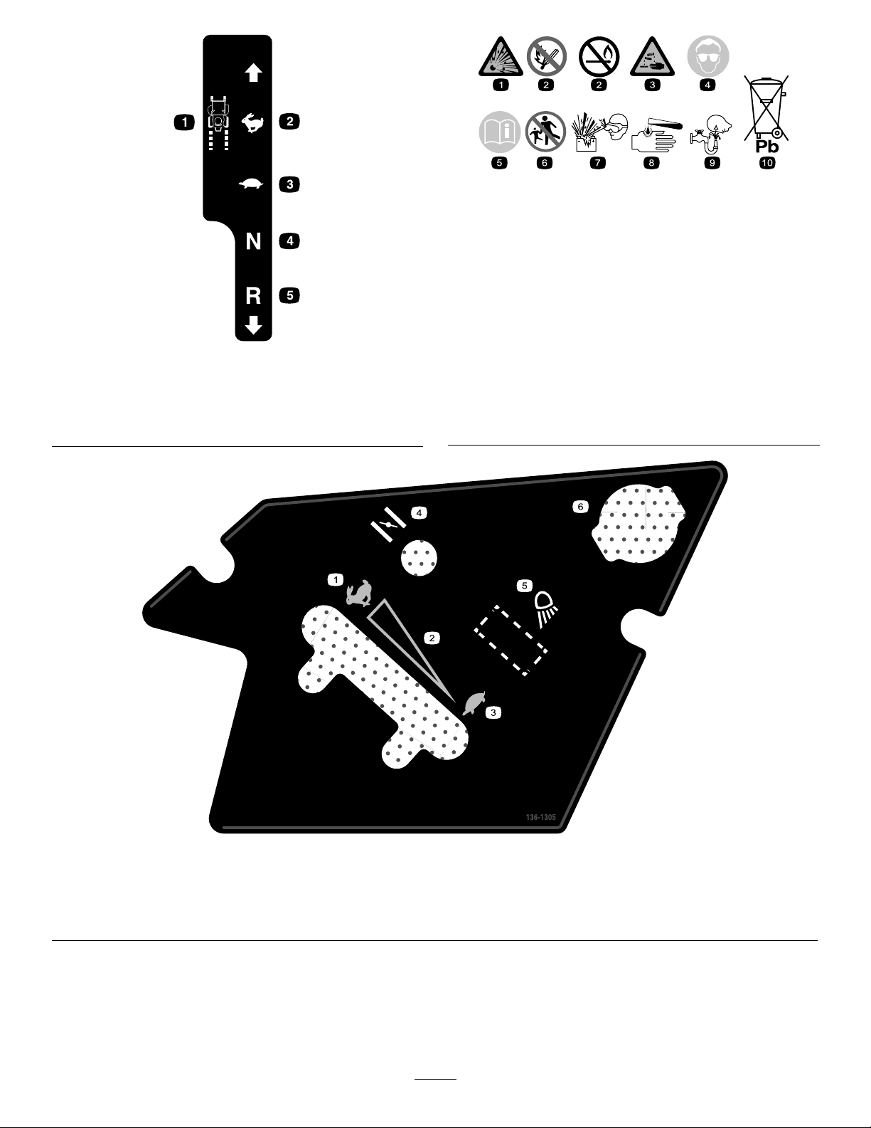
decal126-7816
126-7816
126-4363
1.Cutting/dismembermenthazard,fanandentanglement
hazard,belt.Shutofftheengineandremovekeybefore
adjusting,servicingorcleaning.
decal126-4363
1.Height-of-cut
decal126-8161
126-8161
1.ReadOperator’smanual
2.Slideseatforward
3.Pressdownonlatchto
unlockseat
4.Rotateseat
8
Page 9
126–8172
1.Parkingbrakedisengaged2.Parkingbrakeengaged
decal132-0904
ToroEngineOnly
1.Shutdownengineatfullthrottle
decalptosymbols
PTOSwitchSymbols
1.PTO–disengage2.PTO–engage
decal126-8172
1.ReadtheOperator’s
Manual
1.Oildrain
126-9939
131-1097
ToroEnginesOnly
2.Filltobottomofllerneck;
warning–donotoverllthe
tank
decaltransportlock
TransportLock
1.Heightofcut
decal126-9939
decal131-1097
2.Pulluptounlockthe
transportlock
decalmotioncntrllh-126-6194
LeftMotionControl
1.Machinespeed4.Neutral
2.Fast5.Reverse
3.Slow
9
Page 10
decalbatterysymbols
BatterySymbols
Someorallofthesesymbolsareonyourbattery.
RightMotionControl
1.Machinespeed4.Neutral
2.Fast5.Reverse
3.Slow
1.Explosionhazard
6.Keepbystandersasafe
distancefromthebattery.
2.Nore,opename,or
smoking
7.Weareyeprotection;
explosivegasescan
causeblindnessandother
injuries.
3.Causticliquid/chemical
decalmotioncntrlrh-126-6183
burnhazard
8.Batteryacidcancause
blindnessorsevereburns.
4.Weareyeprotection.9.Flusheyesimmediately
withwaterandgetmedical
helpfast.
5.ReadtheOperator's
Manual.
10.Containslead;donot
discard
136-1305
1.Fast
2.Continuousvariablesetting5.Worklight(optional)
3.Slow
4.Choke
6.Powerpoint
10
decal136-1305
Page 11
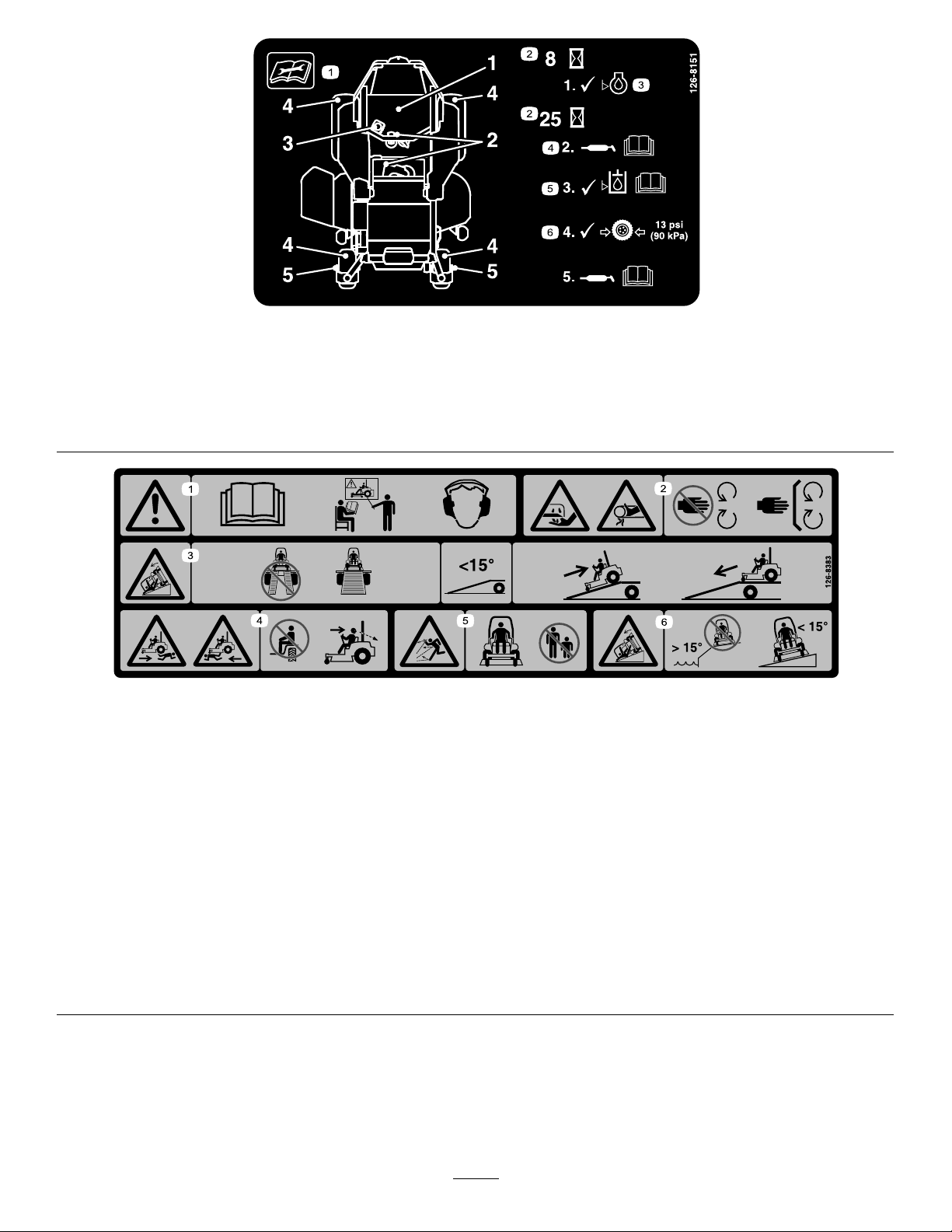
decal126-8151
126-8151
1.Readtheinstructionsbeforeservicingorperforming
4.RefertotheOperator'smanualforgreaseinstructions
maintenance
2.Timeinterval
5.CheckhydraulicoillevelandrefertotheOperator'smanual
forfurtherinstructions
3.Checkoillevel6.Checktirepressure
126-8383
MachineswithoutMyRideOnly
Note:Thismachinecomplieswiththeindustrystandardstabilitytestinthestaticlateralandlongitudinaltestswiththemaximum
recommendedslopeindicatedonthedecal.ReviewtheinstructionsforoperatingthemachineonslopesintheOperator’sManualas
wellastheconditionsinwhichyouwouldoperatethemachinetodeterminewhetheryoucanoperatethemachineinthoseconditions
onthatdayandatthatsite.Changesintheterraincanresultinachangeinslopeoperationforthemachine.Ifpossible,keepthe
cuttingunitsloweredtothegroundwhileoperatingthemachineonslopes.Raisingthecuttingunitswhileoperatingonslopescan
causethemachinetobecomeunstable.
decal126-8383
1.Warning—readtheOperator’sManual;donotoperatethis
machineunlessyouaretrained;wearhearingprotection.
2.Cutting,dismembering,andentanglementhazard—keep
handsawayfrommovingparts;keepallguardsandshieldsin
place.
3.Ramphazard—whenloadingontoatrailer,donotusedual
ramps;onlyuseasingularrampwideenoughforthemachine
andthathasaninclinelessthan15°;backuptheramp(in
reverse)anddriveforwardofftheramp.
4.Bodilyharmhazard—donotcarrypassengers;lookbehind
youwhenmowinginreverse.
5.Thrownobjecthazard—keepbystandersaway.
6.Tippinghazardonslopes—donotuseonslopesnearopen
water;donotuseonslopesgreaterthan15°.
11
Page 12
ProductOverview
IgnitionSwitch
Usethisswitchtostartthemowerengine.Ithas3
positions:START,RUN,andOFF.
ChokeControl
Usethechoketostartacoldengine.Pullthechoke
knobuptoengageit.Pushthechokeknobdownto
disengageit(Figure6).
ThrottleControl
Thethrottlecontrolstheenginespeed,andithasa
continuous-variablesettingfromtheSLOWtoFAST
position(Figure6).
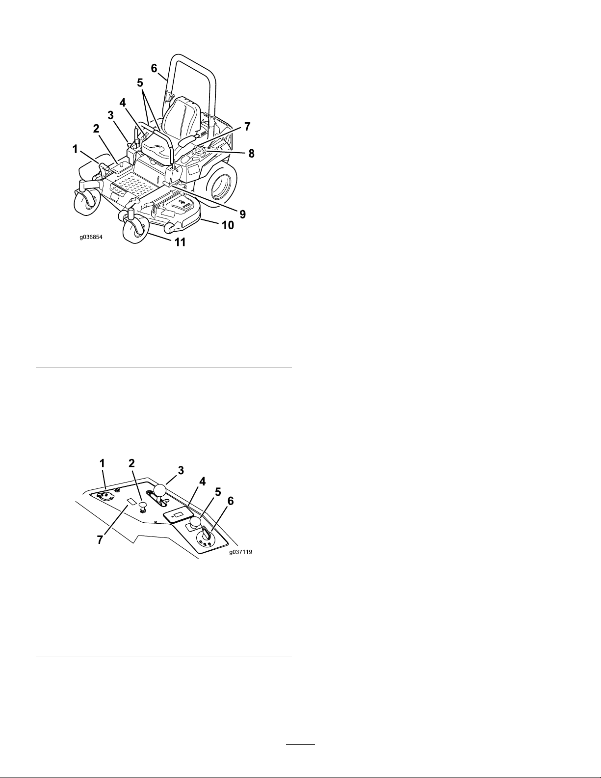
Figure5
1.Height-of-cutdeck-lift
pedal
2.Height-of-cutpositions
3.Transportlock9.Parking-brakelever
4.Controls
5.Motion-controllevers
6.Rollbar
7.Seatbelt
8.Fuelcap
10.Mowerdeck
11.Casterwheel
Controls
Becomefamiliarwithallthecontrolsbeforeyoustart
theengineandoperatethemachine(Figure5and
Figure6).
g036854
Blade-ControlSwitch(Power
Takeoff)
Theblade-controlswitch(PTO)engagesand
disengagespowertothemowerblades(Figure6).
HourMeter
Thehourmeterrecordsthenumberofhoursthe
enginehasoperated.Itoperateswhentheengine
isrunning.Usethesetimesforschedulingregular
maintenance(Figure6).
Safety-InterlockIndicators
Therearesymbolsonthehourmeterthatindicate
withablacktrianglethattheinterlockcomponentis
positionedcorrectly(Figure7).
Battery-IndicatorLight
IfyouturntheignitionkeytotheONpositionfora
fewseconds,thebatteryvoltagedisplaysinthearea
wherethehoursarenormallydisplayed.
1.Powerport
2.Chokecontrol
3.Throttlecontrol
4.Hourmeter
Figure6
5.PTOSwitch
6.Ignitionswitch
7.Switchpositionforoptional
lightkit
g037119
Thebatterylightturnsonwhentheignitionisturned
onandwhenthechargeisbelowthecorrectoperating
level(Figure7).
12
Page 13

Figure7
g187133
1.Safety-interlocksymbols
2.Hourmeter
3.Batterylight
Motion-ControlLevers
Usethemotion-controlleverstodrivethemachine
forward,reverse,andturneitherdirection.
Neutral-LockPosition
UsetheNEUTRAL-LOCKpositionwiththe
safety-interlocksystemtodeterminetheNEUTRAL
position.
Fuel-ShutoffValve
Closethefuel-shutoffvalve(behindtheseat)when
transportingorstoringthemower.
Attachments/Accessories
AselectionofT oroapprovedattachmentsand
accessoriesisavailableforusewiththemachineto
enhanceandexpanditscapabilities.Contactyour
AuthorizedServiceDealerorDistributororgoto
www.T oro.comforalistofallapprovedattachments
andaccessories.
13
Page 14

Specications
Note:Specicationsanddesignaresubjecttochangewithoutnotice.
Width—SideDischargeMowerDecks:
122cmmowerdeck132cmmowerdeck
Withoutmowerdeck
Deectorup133cm(53inches)144cm(56-3/4inches)
Deectordown160cm(63-1/4inches)171cm(67-1/4inches)
Length—SideDischargeMowerDecks:
Length
Height:
RollBar-UpRollBar-Down
179cm(70-1/2inches)125cm(49inches)
Weight:
MachinesWeight
122cmsidedischargemachines849-937lb
132cmsidedischargemachines862-957lb
121cm(47-1/2inches)124cm(49inches)
122cmmowerdeck132cmmowerdeck
208cm(82inches)208cm(82inches)
(385-425kg)
(391–434kg)
Operation
Note:Determinetheleftandrightsidesofthe
machinefromthenormaloperatingposition.
BeforeOperation
BeforeOperationSafety
GeneralSafety
•Neverallowchildrenoruntrainedpeopleto
operateorservicethemachine.Localregulations
mayrestricttheageoftheoperator.Theowner
isresponsiblefortrainingalloperatorsand
mechanics.
•Becomefamiliarwiththesafeoperationofthe
equipment,operatorcontrols,andsafetysigns.
•Knowhowtostopthemachineandenginequickly.
•Checkthatoperator-presencecontrols,safety
switches,andshieldsareattachedandfunctioning
properly.Donotoperatethemachineunlessthey
arefunctioningproperly.
•Beforemowing,alwaysinspectthemachineto
ensurethattheblades,bladebolts,andcutting
assembliesareingoodworkingcondition.
Replacewornordamagedbladesandboltsinsets
topreservebalance.
•Inspecttheareawhereyouwillusethemachine
andremoveallobjectsthatthemachinecould
throw.
•Evaluatetheterraintodeterminetheappropriate
equipmentandanyattachmentsoraccessories
requiredtooperatethemachineproperlyand
safely.
FuelSafety
•Toavoidpersonalinjuryorpropertydamage,use
extremecareinhandlingfuel.Fuelvaporsare
ammableandexplosive.
•Extinguishallcigarettes,cigars,pipes,andother
sourcesofignition.
•Useonlyanapprovedfuelcontainer.
•Donotremovethefuelcaporaddfueltothefuel
tankwhiletheengineisrunningorwhilehot.
•Donotrefuelthemachineindoors.
•Donotstorethemachineorfuelcontainerwhere
thereisanopename,spark,orpilotlight,such
asonawaterheateroronotherappliances.
14
Page 15

•Donotllcontainersinsideavehicleoronatruck
ortrailerbedwithaplasticliner.Alwaysplace
containersontheground,awayfromyourvehicle
beforelling.
•Removetheequipmentfromthetruckortrailer
andrefuelitwhileitisontheground.Ifthisisnot
possible,thenrefuelfromaportablecontainer
ratherthanafuel-dispensernozzle.
•Donotoperatethemachinewithouttheentire
exhaustsysteminplaceandinproperworking
condition.
•Keepthefuel-dispensernozzleincontactwith
therimofthefueltankorcontaineropeningat
alltimesuntilfuelingiscomplete.Donotusea
nozzlelock-opendevice.
•Ifyouspillfuelonyourclothing,changeyour
clothingimmediately.Wipeupanyfuelthatspills.
•Neveroverllthefueltank.Replacethefuelcap
andtightenitsecurely.
•Storefuelinanapprovedcontainerandkeepit
outofthereachofchildren.Neverbuymorethan
a30-daysupplyoffuel.
RecommendedFuel
•Forbestresults,useonlyclean,fresh(lessthan
30daysold),unleadedgasolinewithanoctane
ratingof87orhigher((R+M)/2ratingmethod).
•Ethanol:Gasolinewithupto10%ethanol
(gasohol)or15%MTBE(methyltertiarybutyl
ether)byvolumeisacceptable.Ethanoland
MTBEarenotthesame.Gasolinewith15%
ethanol(E15)byvolumeisnotapprovedforuse.
Neverusegasolinethatcontainsmorethan
10%ethanolbyvolume,suchasE15(contains
15%ethanol),E20(contains20%ethanol),orE85
(containsupto85%ethanol).Usingunapproved
gasolinemaycauseperformanceproblemsand/or
enginedamagewhichmaynotbecoveredunder
warranty.
•Donotusegasolinecontainingmethanol.
•Donotstorefueleitherinthefueltankorfuel
containersoverthewinterunlessyouuseafuel
stabilizer.
•Donotaddoiltogasoline.
•Donotllthefueltankcompletelyfull.Addfuelto
thefueltankuntilthelevelis6to13mm(1/4to
1/2inch)belowthebottomofthellerneck.This
emptyspaceinthetankallowsfueltoexpand.
–Avoidprolongedbreathingofvapors.
–Keepyourfaceawayfromthenozzleandgas
tankopening.
–Avoidcontactwithskin;washoffspillswith
soapandwater.
Using Stabilizer/Conditioner
Useafuelstabilizer/conditionerinthemachineto
providethefollowingbenets:
•Keepsfuelfreshduringstorageof90daysorless
(drainthefueltankwhenstoringthemachinefor
morethan90days)
•Cleanstheenginewhileitruns
•Eliminatesgum-likevarnishbuildupinthefuel
system,whichcauseshardstarting
Important:Donotusefueladditives
containingmethanolorethanol.
Addthecorrectamountoffuelstabilizer/conditioner
tothefuel.
Note:Afuelstabilizer/conditionerismost
effectivewhenmixedwithfreshfuel.T ominimize
thechanceofvarnishdepositsinthefuelsystem,
usefuelstabilizeratalltimes.
FillingtheFuelTank
1.Parkthemachineonlevelground.
2.Shutofftheengineandengagetheparking
brake.
3.Cleanaroundthefuel-tankcap.
4.Fillthefueltanktothebottomofthellerneck
(Figure8).
15
Page 16
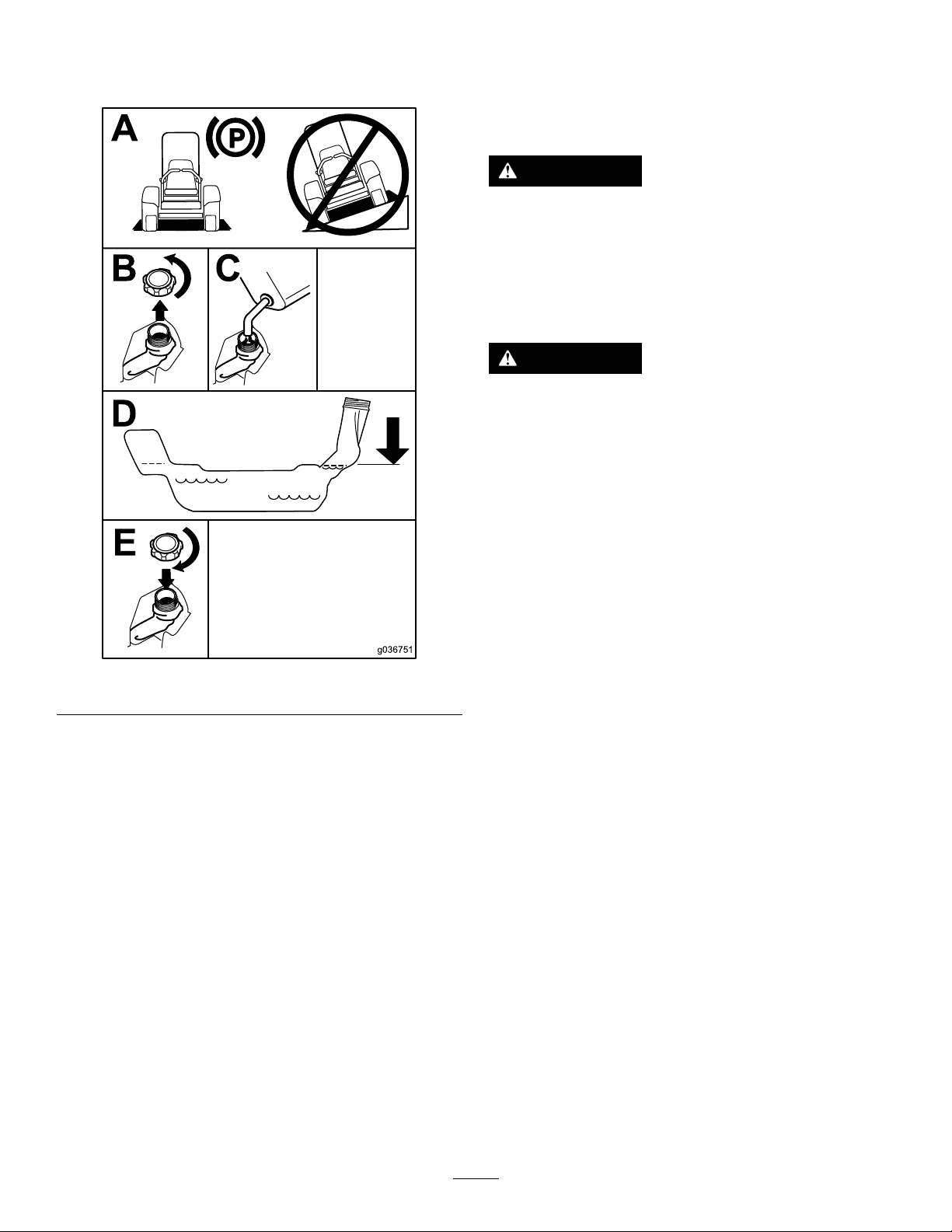
Note:Donotllthefueltankcompletelyfull.
Theemptyspaceinthetankallowsthegasoline
toexpand.
Usingthe Rollover-ProtectionSystem (ROPS)
WARNING
Toavoidinjuryordeathfromrollover:keep
therollbarinthefullyraisedlockedposition
andusetheseatbelt.
Ensurethattheseatissecuredtothe
machine.
WARNING
Thereisnorolloverprotectionwhentheroll
barisinthedownposition.
•Lowertherollbaronlywhenabsolutely
necessary.
•Donotweartheseatbeltwhentherollbar
isinthedownposition.
Figure8
CheckingtheEngine-Oil Level
Beforeyoustarttheengineandusethemachine,
checktheoillevelintheenginecrankcase;referto
CheckingtheEngine-OilLevel(page37).
BreakinginaNewMachine
Newenginestaketimetodevelopfullpower.Mower
decksanddrivesystemshavehigherfrictionwhen
new,placingadditionalloadontheengine.Allow
40to50hoursofbreak-intimefornewmachinesto
developfullpowerandbestperformance.
•Driveslowlyandcarefully.
•Raisetherollbarassoonasclearance
permits.
•Checkcarefullyforoverheadclearances
(i.e.,branches,doorways,electricalwires)
g036751
beforedrivingunderanyobjectsanddo
notcontactthem.
Important:Lowertherollbaronlywhen
absolutelynecessary.
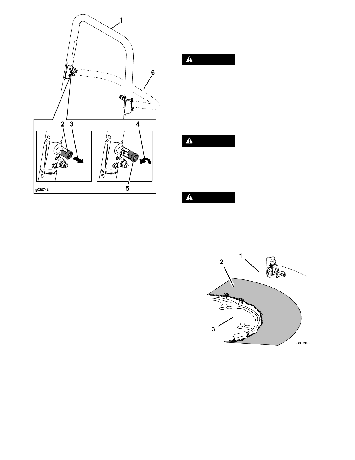
1.T olowertherollbar,applyforwardpressureto
theupperpartoftherollbar.
2.Pullbothknobsoutandrotatethem90degrees
sotheyarenotengaged(Figure9).
3.Lowertherollbartothedownposition(Figure
9).
16
Page 17
ThinkSafetyFirst
Pleasereadallsafetyinstructionsandsymbolsinthe
safetysection.Knowingthisinformationcouldhelp
youorbystandersavoidinjury .
DANGER
Operatingthemachineonwetgrassorsteep
slopescancauseslidingandlossofcontrol.
•Donotoperateonslopesgreaterthan15
degrees.
•Reducespeedanduseextremecautionon
slopes.
•Donotoperatethemachinenearwater.
DANGER
Wheelsdroppingoveredgescancause
rollovers,whichmayresultinseriousinjury ,
death,ordrowning.
Donotoperatethemachineneardrop-offs.
Figure9
1.Rollbarintheupright
position
2.ROPSknobinthelatched
position
3.PulltheROPSknobout.6.Rollbarinthefolded
4.RotatetheROPSknob90
degrees.
5.ROPSknobinthe
unlatchedposition
position
4.T oraisetherollbar,raisetherollbartothe
operatingpositionandrotatetheknobsuntil
theymovepartiallyintothegrooves(Figure9).
5.Raisetherollbartothefulluprightpositionwhile
pushingontheupperrollbarsothatthepins
snapintopositionwhentheholesalignwiththe
pins(Figure9).
Important:Alwaysusetheseatbeltwiththe
rollbarintheraisedposition.
6.Pushontherollbarandensurethatbothpins
areengaged.
g036746
DANGER
Operatingthemachinewhiletherollbaris
downmayleadtoseriousinjuryordeathin
theeventofarollover.
Alwayskeeptherollbarinthefullyraisedand
lockedpositionandusetheseatbelt.
g000963
Figure10
1.SafeZone—usethe
machinehereonslopes
lessthan15degreesor
atareas.
2.DangerZone—usea
walk-behindmowerand/or
ahandtrimmeronslopes
greaterthan15degrees
andneardrop-offsor
water.
17
3.Water
Page 18
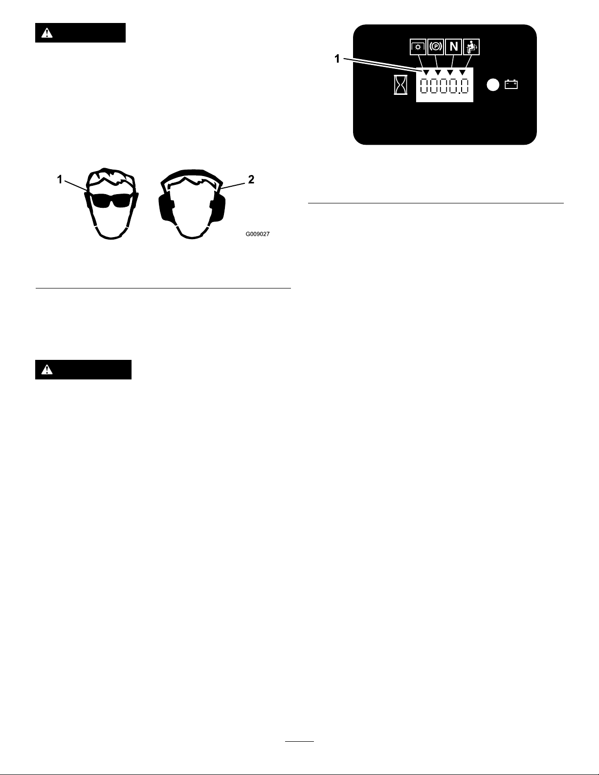
CAUTION
Thismachineproducessoundlevelsin
excessof85dBAattheoperator’searand
cancausehearinglossthroughextended
periodsofexposure.
Wearhearingprotectionwhenoperatingthis
machine.
Useprotectiveequipmentforyoureyes,ears,hands,
feet,andhead.
g009027
Figure11
1.Weareyeprotection.2.Wearhearingprotection.
UsingtheSafety-Interlock System
WARNING
Ifsafety-interlockswitchesaredisconnected
ordamaged,themachinecouldoperate
unexpectedlycausingpersonalinjury.
•Donottamperwiththeinterlockswitches.
•Checktheoperationoftheinterlock
switchesdaily ,andreplaceanydamaged
switchesbeforeoperatingthemachine.
Understandingthe Safety-InterlockSystem
Thesafety-interlocksystemisdesignedtopreventthe
enginefromstartingunless:
•Theparkingbrakeisengaged.
•Theblade-controlswitch(PTO)isdisengaged.
•Themotion-controlleversareintheNEUTRAL-LOCK
position.
Thesafety-interlocksystemisalsodesignedtoshutoff
theenginewhenthetractioncontrolsaremovedfrom
thelockedpositionwiththeparkingbrakeengagedor
ifyourisefromtheseatwhenthePTOisengaged.
Thehourmeterhassymbolstonotifytheuserwhen
theinterlockcomponentisinthecorrectposition.
Whenthecomponentisinthecorrectposition,a
trianglelightsupinthecorrespondingsquare.
g187670
Figure12
1.Triangleslightupwhentheinterlockcomponentsareinthe
correctposition
TestingtheSafety-Interlock System
ServiceInterval:Beforeeachuseordaily
Testthesafety-interlocksystembeforeyouusethe
machineeachtime.Ifthesafetysystemdoesnot
operateasdescribedbelow,haveanAuthorized
ServiceDealerrepairthesafetysystemimmediately .
1.Sittingontheseat,engagetheparkingbrake
andmovetheblade-controlswitch(PTO)tothe
ONposition.Trystartingtheengine;theengine
shouldnotstart.
2.Sittingontheseat,engagetheparkingbrake
andmovetheblade-controlswitch(PTO)tothe
OFFposition.Moveeithermotion-controllever
(outoftheNEUTRAL-LOCKposition).Trystarting
theengine;theengineshouldnotstart.Repeat
fortheothercontrollever.
3.Sittingontheseat,engagetheparkingbrake,
movetheblade-controlswitch(PTO)totheOFF
position,andmovethemotion-controllevers
totheNEUTRAL-LOCKposition.Nowstartthe
engine.Whiletheengineisrunning,disengage
theparkingbrake,engagetheblade-control
switch(PTO),andriseslightlyfromtheseat;the
engineshouldshutoff.
4.Sittingontheseat,engagetheparkingbrake,
movetheblade-controlswitch(PTO)totheOFF
position,andmovethemotion-controllevers
totheNEUTRAL-LOCKposition.Nowstartthe
engine.Whiletheengineisrunning,center
eithermotioncontrolandmove(forwardor
reverse);theengineshouldshutoff.Repeatfor
othermotioncontrol.
5.Sittingontheseat,disengagetheparkingbrake,
movetheblade-controlswitch(PTO)totheOFF
position,andmovethemotion-controllevers
totheNEUTRAL-LOCKposition.Trystartingthe
engine;theengineshouldnotstart.
18
Page 19
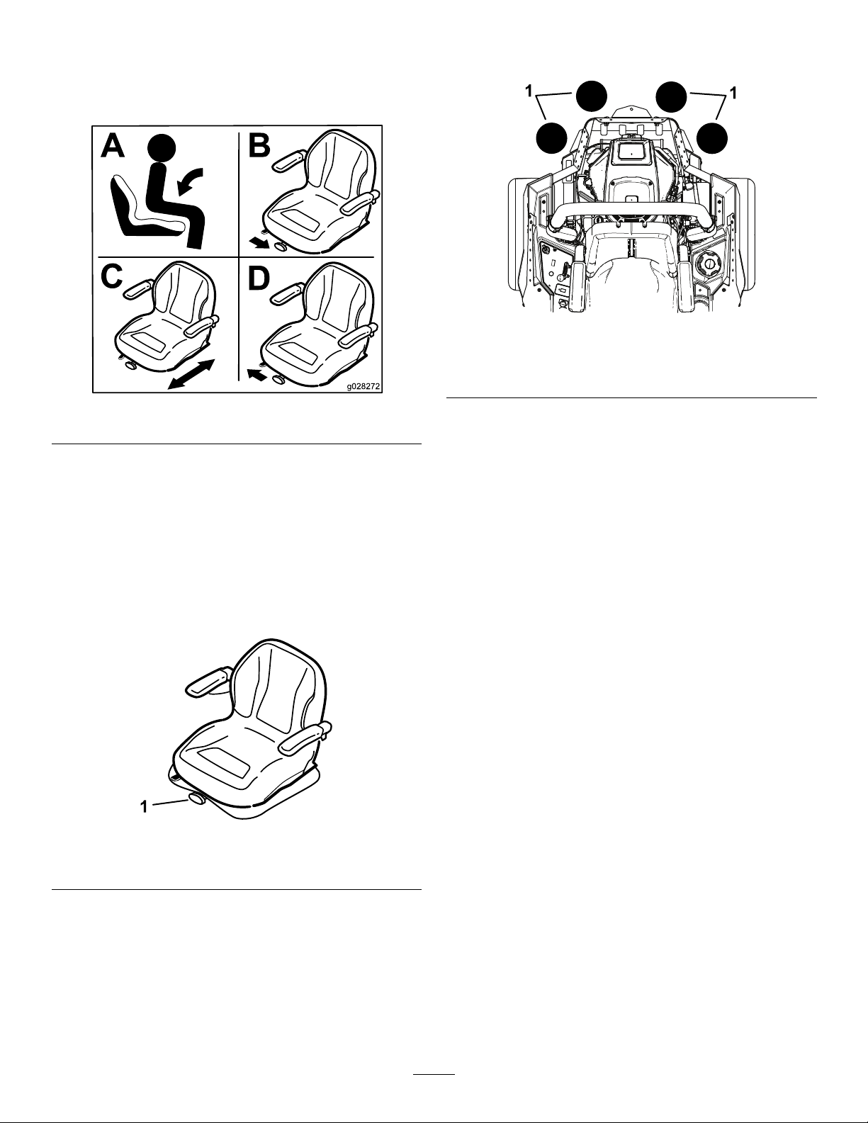
PositioningtheSeat
Theseatcanmoveforwardandbackward(Figure13).
Positiontheseatwhereyouhavethebestcontrolof
themachineandaremostcomfortable.
Figure13
showninFigure15,addafront-weightkit.Contact
yourauthorizedservicedealerforthefront-weightkit.
g037417
Figure15
1.Addafront-weightkitwhen2ormoreaccessory-mountkits
areinstalledatthesepositions.
g028272
DuringOperation
ChangingtheSeat Suspension
Theseatisadjustabletoprovideasmoothand
comfortableride.Positiontheseatwhereyouare
mostcomfortable.
Toadjustit,turntheknobinfronteitherdirectionto
providethebestcomfort(Figure14).
Figure14
1.Seat-suspensionknob
UsingAttachmentsand Accessories
UseonlyT oroapprovedattachmentsandaccessories.
DuringOperationSafety
GeneralSafety
•Theowner/operatorcanpreventandisresponsible
foraccidentsthatmaycausepersonalinjuryor
propertydamage.
•Wearappropriateclothing,includingeye
protection;slip-resistant,substantialfootwear;and
hearingprotection.Tiebacklonghairanddonot
wearjewelry.
•Donotoperatethemachinewhileill,tired,or
undertheinuenceofalcoholordrugs.
•Nevercarrypassengersonthemachineandkeep
bystandersandpetsawayfromthemachine
duringoperation.
g024881
•Operatethemachineonlyingoodvisibilitytoavoid
holesorhiddenhazards.
•Avoidmowingonwetgrass.Reducedtraction
couldcausethemachinetoslide.
•Ensurethatalldrivesareinneutral,theparking
brakeisengaged,andyouareintheoperating
positionbeforeyoustarttheengine.
•Keepyourhandsandfeetawayfromthecutting
units.Keepclearofthedischargeopeningatall
times.
Ifmorethanoneaccessory-mountkit(i.e.bucketkitor
universalmountkit)isaddedtoanyofthe4locations
•Lookbehindanddownbeforebackinguptobe
sureofaclearpath.
19
Page 20
•Usecarewhenapproachingblindcorners,shrubs,
trees,orotherobjectsthatmayobscureyour
vision.
•Keeptherollbarinsafeoperatingconditionby
thoroughlyinspectingitperiodicallyfordamage
andkeepingallthemountingfastenerstight.
•Donotmowneardrop-offs,ditches,or
embankments.Themachinecouldsuddenlyroll
overifawheelgoesovertheedgeoriftheedge
givesway .
•Stopthebladeswheneveryouarenotmowing.
•Stopthemachineandinspectthebladesafter
strikinganobjectorifthereisanabnormal
vibrationinthemachine.Makeallnecessary
repairsbeforeresumingoperation.
•Slowdownandusecautionwhenmakingturns
andcrossingroadsandsidewalkswiththe
machine.Alwaysyieldtheright-of-way.
•Disengagethedrivetothecuttingunitandshut
offtheenginebeforeadjustingtheheightof
cut(unlessyoucanadjustitfromtheoperating
position).
•Neverrunanengineinanareawhereexhaust
gasesareenclosed.
•Neverleavearunningmachineunattended.
•Beforeleavingtheoperatingposition(including
toemptythecatchersortounclogthechute),do
thefollowing:
•Replaceadamagedrollbar.Donotrepairoralter
it.
SlopeSafety
•Slowdownthemachineanduseextracareon
hillsides.Travelupanddownonhillsides.Turf
conditionscanaffectthestabilityofthemachine.
•Avoidturningthemachineonslopes.Ifyoumust
turnthemachine,turnitslowlyandgradually
downhill,ifpossible.
•Donotturnthemachinesharply .Usecarewhen
reversingthemachine.
•Useextracarewhileoperatingthemachinewith
attachments;theycanaffectthestabilityofthe
machine.
OperatingtheParking Brake
Alwaysengagetheparkingbrakewhenyoustopthe
machineorleaveitunattended.
–Stopthemachineonlevelground.
–Disengagethepowertake-offandlowerthe
attachments.
–Engagetheparkingbrake.
–Shutofftheengineandremovethekey.
–Waitforallmovingpartstostop.
•Donotoperatethemachinewhenthereistherisk
oflightning.
•Donotusethemachineasatowingvehicle.
•Donotchangethegovernorspeedoroverspeed
theengine.
•Useaccessoriesandattachmentsapprovedby
Toroonly.
RolloverProtectionSystem (ROPS)Safety
•Donotremovetherollbarfromthemachine.
•Ensurethattheseatbeltisattachedandthatyou
canreleaseitquicklyinanemergency.
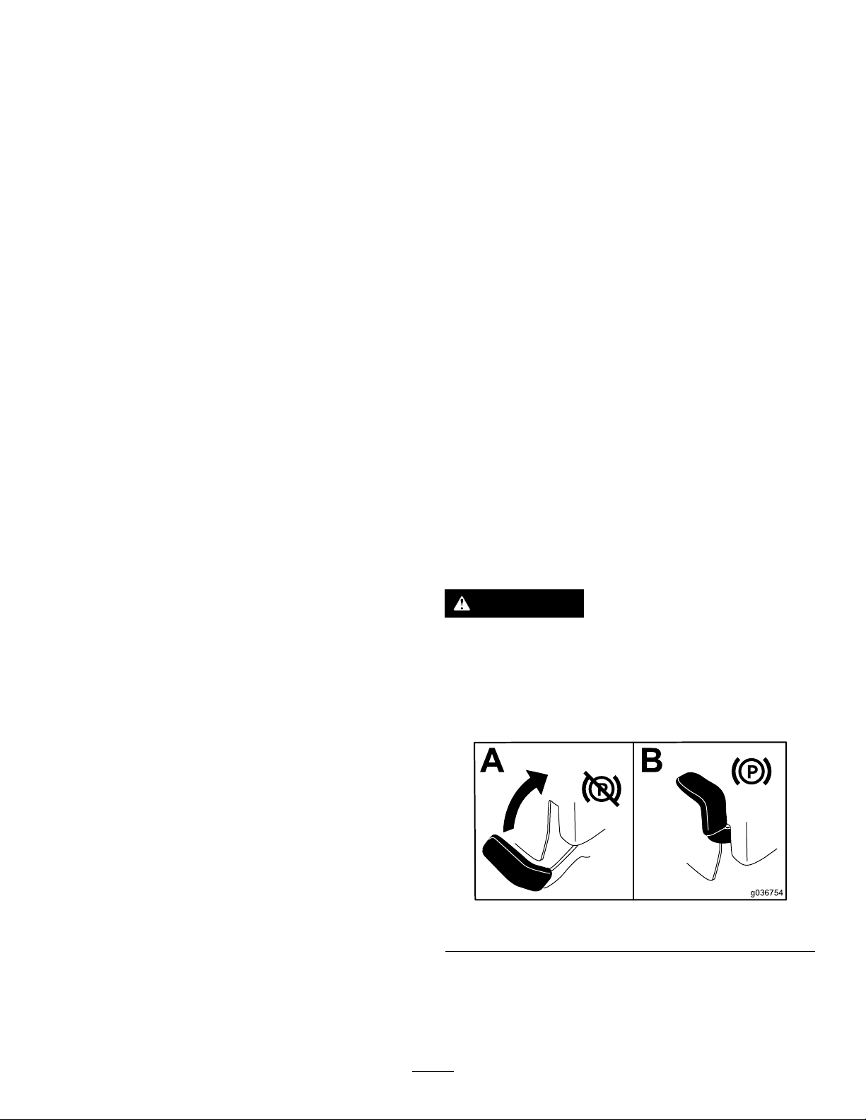
EngagingtheParkingBrake
WARNING
Theparkingbrakemaynotholdthemachine
parkedonaslopeandcouldcausepersonal
injuryorpropertydamage.
Donotparkonslopesunlessthewheelsare
chockedorblocked.
g036754
Figure16
•Alwayswearyourseatbeltwhentherollbarisup.
•Checkcarefullyforoverheadobstructionsanddo
notcontactthem.
20
Page 21
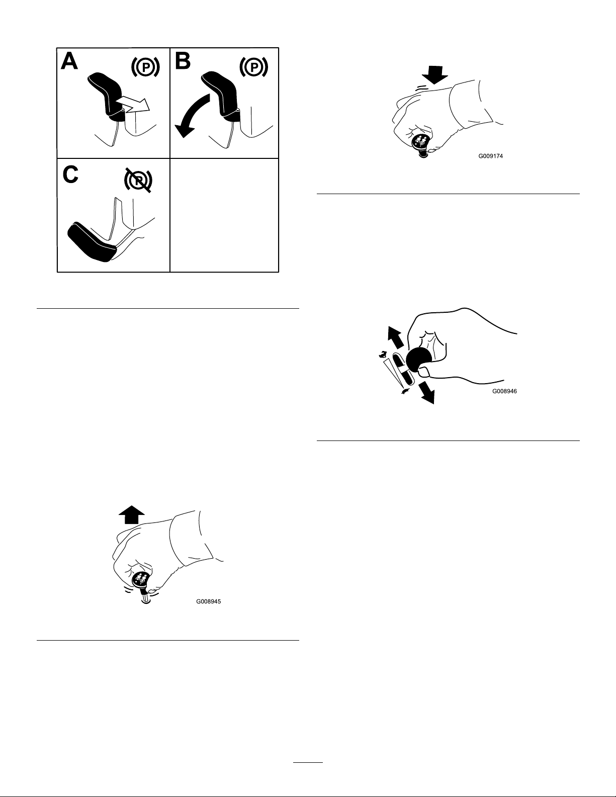
DisengagingtheParkingBrake
Figure17
DisengagingtheBlade-Control Switch(PTO)
g009174
Figure19
OperatingtheThrottle
YoucanmovethethrottlecontrolbetweentheFAST
andSLOWpositions(Figure20).
g192635
AlwaysusetheFASTpositionwhenturningonthe
mowerdeckwiththeblade-controlswitch(PTO).
OperatingtheMower Blade-ControlSwitch(PTO)
Theblade-controlswitch(PTO)startsandstopsthe
mowerbladesandanypoweredattachments.
EngagingtheBlade-Control Switch(PTO)
Note:Engagingtheblade-controlswitch(PTO)with
thethrottlepositionathalforlesscausesexcessive
weartothedrivebelts.
Figure18
g008946
Figure20
OperatingtheChoke
Usethechoketostartacoldengine.
1.Iftheengineiscold,usethechoketostartthe
engine.
2.Pullupthechokeknobtoengagethechoke
beforeusingtheignitionswitch(Figure21).
3.Pushdownthechokeknobtodisengagethe
chokeafterstartingtheengine(Figure21).
g008945
21
Page 22

Figure21
1.ONposition2.OFFposition
StartingandShuttingOff theEngine
StartingtheEngine
1.Raisetherollbarupandlockintoplace,siton
theseat,andfastentheseatbelt.
2.MovethemotioncontrolstotheNEUTRAL-LOCK
position.
3.Engagetheparkingbrake;refertoEngagingthe
ParkingBrake(page20).
4.Movetheblade-controlswitch(PTO)totheOFF
position(Figure23).
5.Movethethrottlelevermidwaybetweenthe
SLOWandFASTpositions.
g008959
OperatingtheIgnition Switch
1.TurntheignitionkeytotheSTARTposition
(Figure22).
Note:Whentheenginestarts,releasethekey.
Important:Donotengagethestarterfor
morethan5secondsatatime.Iftheengine
failstostart,wait15secondsbetween
attempts.Failuretofollowtheseinstructions
canburnoutthestartermotor.
Note:Youmayneedmultipleattemptstostart
theenginewhenyoustartitthersttimeafter
thefuelsystemhasbeenwithoutfuelcompletely.
g036838
Figure23
6.TurntheignitionkeytotheSTARTposition
(Figure24).
Note:Whentheenginesstarts,releasethekey.
Figure22
2.TurntheignitionkeytotheSTOPpositiontoshut
offtheengine.
Important:Donotengagestarterformore
g008947
than5secondsatatime.Iftheenginefails
tostartallowa15-secondcool-downperiod
betweenattempts.Failuretofollowthese
instructionscanburnoutthestartermotor.
Note:Additionalstartingcyclesmaybe
requiredwhenstartingtheenginefortherst
22
Page 23

timeafterthefuelsystemhasbeenwithoutfuel
completely.
Figure24
ShuttingOfftheEngine
CAUTION
Childrenorbystandersmaybeinjuredifthey
moveorattempttooperatethemachinewhile
itisunattended.
g008947
Alwaysremovetheignitionkeyandengage
theparkingbrakewhenleavingthemachine
unattended,evenifjustforafewminutes.
MovethethrottletotheFASTpositionandturnthe
switchtotheOFFposition.
g037049
Figure25
Important:Makesurethatthefuel-shutoffvalve
isclosedbeforetransportingorstoringthe
machine,asfuelleakagemayoccur.Engagethe
parkingbrakebeforetransporting.Makesurethat
youremovethekeyasthefuelpumpmayrunand
causethebatterytolosecharge.
23
Page 24

UsingtheMotion-Control
DrivingtheMachine
Levers
Thedrivewheelsturnindependently ,poweredby
hydraulicmotorsoneachaxle.Youcanturn1side
inreversewhileyouturntheotherforward,causing
themachinetospinratherthanturn.Thisgreatly
improvesthemachinemaneuverabilitybutmay
requiretimeforyoutoadapttohowitmoves.
Thethrottlecontrolregulatestheenginespeedas
measuredinrpm(revolutionsperminute).Place
thethrottlecontrolintheFASTpositionforbest
performance.Alwaysoperateinthefullthrottle
positionwhenmowing.
CAUTION
Machinecanspinveryrapidly.Operatormay
losecontrolofmachineandcausepersonal
injuryordamagetomachine.
•Usecautionwhenmakingturns.
•Slowthemachinedownbeforemaking
sharpturns.
Figure26
1.Motion-control
lever—NEUTRAL-LOCK
position
2.Center,unlockedposition5.Frontofmachine
3.Forward
4.Backward
c:\data\documentum\checkout\g004532
24
Page 25

DrivingForward
DrivingBackward
Note:Theenginestopswhenyoumovethe
traction-controlwiththeparkingbrakeengaged.
Tostop,pullthemotion-controlleverstotheNEUTRAL
position.
1.Disengagetheparkingbrake;referto
DisengagingtheParkingBrake(page21).
2.Movetheleverstothecenter,unlockedposition.
3.T ogoforward,slowlypushthemotion-control
leversforward(Figure27).
1.Movetheleverstothecenter,unlockedposition.
2.T ogobackward,slowlypullthemotion-control
leversrearward(Figure28).
g008953
Figure28
Figure27
g008952
25
Page 26

AdjustingtheHeight-of-Cut
UsingtheTransportLock
Thetransportlockhas2positions,andisusedwith
thedeck-liftpedal.ThereisaLOCKpositionand
anUNLOCKpositionforthetransportpositionofthe
mowerdeck(Figure29).
AdjustingtheHeight-of-CutPin
Adjusttheheight-of-cutfrom38to127mm(1-1/2to5
inches)in6mm(1/4inch)incrementsbymovingthe
height-of-cutpinintodifferentholelocations.
1.MovethetransportlocktotheLOCKposition.
2.Pushonthedeck-liftpedalwithyourfootand
raisethemowerdecktotheTRANSPORTposition
(alsothe127mmor5inchcutting-height
position)asshowninFigure30.
3.T oadjust,removethepinfromtheheight-of-cut
bracket(Figure30).
4.Selectaholeintheheight-of-cutbracket
correspondingtotheheight-of-cutdesired,and
insertthepin(Figure30).
5.Pushonthedecklift,pulluponthetransport
lockknob,andslowlylowerthemowerdeck.
Figure29
Transport-LockPositions
1.Transportlockknob3.UNLOCKposition—The
2.LOCKposition—The
mowerdecklocksintothe
transportposition.
mowerdeckdoesnotlock
intothetransportposition.
g036745
Figure30
1.Deck-liftpedal3.Height-of-cutpin
2.Height-of-cutholes
g037050
AdjustingtheAnti-Scalp
4.Transportlockknob
Rollers
Wheneveryouchangetheheight-of-cut,adjustthe
heightoftheanti-scalprollers.
1.Disengagetheblade-controlswitch(PTO),move
themotion-controlleverstotheNEUTRAL-LOCK
position,andengagetheparkingbrake.
2.Stoptheengine,removethekey,andwait
forallmovingpartstostopbeforeleavingthe
operatingposition.
26
Page 27

Figure31
1.Anti-scalproller4.Flangenut
2.Spacer
3.Bushing
1.Flangenut4.Anti-scalproller
2.Bolt5.Bushing
3.Spacer
5.Bolt
Figure32
CAUTION
Childrenorbystandersmaybeinjuredifthey
moveorattempttooperatethemachinewhile
itisunattended.
Alwaysremovetheignitionkeyandengage
theparkingbrakewhenleavingthemachine
unattended,evenifjustforafewminutes.
UsingtheSideDischarge
g192815
g036848
Themowerhasahingedgrassdeectorthat
dispersesclippingstothesideanddowntowardthe
turf.
DANGER
Withoutagrassdeector,dischargecover,or
acompletegrass-catcherassemblymounted
inplace,youandothersareexposedtoblade
contactandthrowndebris.Contactwith
rotatingmowerblade(s)andthrowndebris
willcauseinjuryordeath.
•Neverremovethegrassdeectorfrom
themowerbecausethegrassdeector
routesmaterialdowntowardtheturf.Ifthe
grassdeectoriseverdamaged,replaceit
immediately.
•Neverputyourhandsorfeetunderthe
mower.
•Nevertrytoclearthedischargearea
ormowerbladesunlessyoumovethe
blade-controlswitch(PTO)totheOFF
position,rotatetheignitionkeytotheOFF
position,andremovethekey.
•Makesurethatthegrassdeectorisinthe
downposition.
StoppingtheMachine
Tostopthemachine,movethemotion-controllevers
toneutralandthentotheNEUTRAL-LOCKposition,
disengagetheblade-controlswitch(PTO),andturn
theignitionkeytotheOFFposition.
Engagetheparkingbrakewhenyouleavethe
machine;refertoEngagingtheParkingBrake(page
20).Removethekeyfromtheignitionswitch.
OperatingTips
UsingtheFastThrottleSetting
Forbestmowingandmaximumaircirculation,operate
theengineattheFASTposition.Airisrequiredto
thoroughlycutgrassclippings,sodonotsetthe
height-of-cutsolowastototallysurroundthemower
inuncutgrass.Alwaystrytohave1sideofthemower
freefromuncutgrass,whichallowsairtobedrawn
intothemower.
CuttingaLawnfortheFirstTime
Cutgrassslightlylongerthannormaltoensurethat
thecuttingheightofthemowerdoesnotscalpany
unevenground.However,thecuttingheightusedin
27
Page 28

thepastisgenerallythebestonetouse.Whencutting
grasslongerthan15cm(6inches)tall,youmaywant
tocutthelawntwicetoensureanacceptablequality
ofcut.
CuttingaThirdoftheGrassBlade
Itisbesttocutonlyaboutathirdofthegrassblade.
Cuttingmorethanthatisnotrecommendedunless
grassissparse,oritislatefallwhengrassgrows
moreslowly .
AlternatingtheMowingDirection
Alternatethemowingdirectiontokeepthegrass
standingstraight.Thisalsohelpsdisperseclippings
whichenhancesdecompositionandfertilization.
MowingatCorrectIntervals
Grassgrowsatdifferentratesatdifferenttimesof
theyear.T omaintainthesamecuttingheight,mow
moreofteninearlyspring.Asthegrassgrowthrate
slowsinmidsummer,mowlessfrequently .Ifyou
cannotmowforanextendedperiod,rstmowata
highcuttingheight,thenmowagain2dayslaterata
lowerheightsetting.
shreddingthegrassblades.T earingandshredding
turnsgrassbrownattheedges,whichslowsgrowth
andincreasesthechanceofdisease.Checkthe
mowerbladesaftereachuseforsharpness,and
foranywearordamage.Filedownanynicksand
sharpenthebladesasnecessary.Ifabladeis
damagedorworn,replaceitimmediatelywitha
genuineT ororeplacementblade.
AfterOperation
AfterOperationSafety
GeneralSafety
•Cleangrassanddebrisfromthecuttingunits,
mufers,andenginecompartmenttohelpprevent
res.Cleanupoilorfuelspills.
•Shutoffthefuelbeforestoringortransportingthe
machine.
•Disengagethedrivetotheattachmentwhenever
youaretransportingornotusingthemachine.
•Usefull-widthrampsforloadingthemachineinto
atrailerortruck.
UsingaSlowerCuttingSpeed
Toimprovecutquality,useaslowergroundspeed
incertainconditions.
AvoidingCuttingTooLow
Whenmowinguneventurf,raisethecuttingheight
toavoidscalpingtheturf.
StoppingtheMachine
Ifyoumuststoptheforwardmotionofthemachine
whilemowing,aclumpofgrassclippingsmay
dropontoyourlawn.Toavoidthis,moveontoa
previouslycutareawiththebladesengagedoryou
candisengagethemowerdeckwhilemovingforward.
KeepingtheUndersideofthe
MowerClean
Cleanclippingsanddirtfromtheundersideofthe
moweraftereachuse.Ifgrassanddirtbuildupinside
themower,cuttingqualitywilleventuallybecome
unsatisfactory.
•Tiethemachinedownsecurelyusingstraps,
chains,cable,orropes.Bothfrontandrearstraps
shouldbedirecteddownandoutwardfromthe
machine.
•Allowtheenginetocoolbeforestoringthemachine
inanyenclosure.
•Shutoffthefuelbeforestoringortransportingthe
machine.
•Neverstorethemachineorfuelcontainerwhere
thereisanopename,spark,orpilotlight,such
asonawaterheateroronotherappliances.
UsingtheFuel-Shutoff Valve
Thefuel-shutoffvalveislocatedbehindtheseat.
Closethefuel-shutoffvalvefortransport,maintenance,
andstorage.
Ensurethatthefuel-shutoffvalveisopenwhen
startingtheengine.
MaintainingtheBlade(s)
Maintainasharpbladethroughoutthecuttingseason
becauseasharpbladecutscleanlywithouttearingor
28
Page 29

Figure33
NEUTRAL-LOCKposition,applytheparkingbrake,
andremovethekey.
2.Locatethebypassleversbehindtheseat,down
ontheleftandrightsideoftheframe.
3.T opushthemachine,movebothbypassknobs
rearwardandlockthemintoplace(Figure34).
g036849
g008948
4.Disengagetheparkingbrakebeforepushing
themachine.
1.Onposition2.Offposition
Usingthe Drive-Wheel-Release Valves
WARNING
Handsmaybecomeentangledintherotating
drivecomponentsbelowtheenginedeck,
whichcouldresultinseriousinjury.
Shutofftheengine,removethekey,andallow
allmovingpartstostopbeforeaccessingthe
drive-wheel-releasevalves.
WARNING
Theengineandhydraulic-driveunitscan
becomeveryhot.Touchingahotengineor
hydraulic-driveunitscancausesevereburns.
g035062
Figure34
1.Frontofthemachine
2.Rotatebypassreleaseknobcounterclockwisetoloosen.
3.Leverpositionforoperatingthemachine
4.Pulltheleverinthisdirectiontopushthemachine.
5.Leverpositionforpushingthemachine
6.Rotatethebypass-releaseknobclockwisetotighten.
7.Engine
8.Releaselever
5.T orunthemachine,movethebypassknobsto
theFORWARDpositionandlockthemintoplace
(Figure34).
Allowtheengineandhydraulic-driveunits
tocoolcompletelybeforeaccessingthe
drive-wheel-releasevalves.
Thedrive-wheel-releasevalvesarelocatedontheleft
andrightsidesunderneaththeenginedeck.
1.Disengagetheblade-controlswitch(PTO),turn
theignitionkeytooff,movetheleverstothe
29
Page 30

TransportingtheMachine
LoadingtheMachine
Useaheavy-dutytrailerortrucktotransportthe
machine.Ensurethatthetrailerortruckhasall
necessarybrakes,lighting,andmarkingasrequired
bylaw.Pleasecarefullyreadallthesafetyinstructions.
Knowingthisinformationcouldhelpyou,yourfamily,
pets,orbystandersavoidinjury .
WARNING
Drivingonthestreetorroadwaywithout
turnsignals,lights,reectivemarkings,ora
slow-moving-vehicleemblemisdangerous
andcanleadtoaccidents,causingpersonal
injury.
Donotdrivethemachineonapublicstreet
orroadway.
Totransportthemachine:
1.Ifyouareusingatrailer,connectittothetowing
vehicleandconnectthesafetychains.
2.Ifapplicable,connectthetrailerbrakes.
3.Loadthemachineontothetrailerortruck.
4.Shutofftheengine,removethekey,setthe
brake,andclosethefuelvalve.
5.Usethemetaltie-downloopsonthemachineto
securelyfastentheittothetrailerortruckwith
straps,chains,cable,orropes(Figure35).
Useextremecautionwhenloadingorunloading
machinesontoatraileroratruck.Useafull-width
rampthatiswiderthanthemachineforthisprocedure.
Backuptherampanddriveforwarddowntheramp
(Figure36).
Figure36
1.Backthemachineupthe
ramp.
2.Drivethemachineforward
downtheramp.
Important:Donotusenarrowindividualramps
foreachsideofthemachine.
WARNING
Loadingamachineontoatrailerortruck
increasesthepossibilityoftip-overandcould
causeseriousinjuryordeath(Figure37).
•Useextremecautionwhenoperatinga
machineonaramp.
•Useonlyafull-widthramp;donotuse
individualrampsforeachsideofthe
machine.
g028043
1.Tie-downloops
Figure35
•Donotexceeda15-degreeanglebetween
therampandthegroundorbetweenthe
rampandthetrailerortruck.
•Ensurethatthelengthoframpisatleast
4timesaslongastheheightofthetrailer
ortruckbedtotheground.Thisensures
thattherampangledoesnotexceed15
degreesonatground.
•Backuprampsanddriveforwarddown
ramps.
g036851
•Avoidsuddenaccelerationordeceleration
whiledrivingthemachineonarampas
thiscouldcausealossofcontrolora
tip-oversituation.
30
Page 31

Figure37
g027996
1.Full-widthrampinstowed
position
2.Sideviewoffull-width
rampinloadingposition
3.Notgreaterthan
15degrees
4.Rampisatleast4times
aslongastheheightof
thetrailerortruckbedto
theground
5.H=heightofthetraileror
truckbedtotheground
6.Trailer
31
Page 32

Maintenance
RecommendedMaintenanceSchedule(s)
MaintenanceService
Interval
Aftertherst5hours
Aftertherst75hours
Beforeeachuseordaily
Every25hours
Every50hours
Every100hours
MaintenanceProcedure
•ForToroengines—changetheengineoilandlter.
•Changethehydraulic-systemltersanduid.
•Checkthesafetysystem.
•ForToroengines—checktheengine-oillevel.
•Cleantheair-intakescreen.
•Checktheseatbelt.
•Checktherollbarknobs.
•Cleantheenginescreenandtheareaaroundtheengine.
•Cleanaroundtheengine-exhaustsystem.
•Checkthehydraulicuidlevelintheexpansiontank.
•Inspecttheblades.
•Cleanthemowerdeck.
•Greasethefrontcasteraxles.(moreoftenindirtyordustyconditions).
•ForToroengines—cleantheair-cleanerfoamelement(moreoftenindusty,dirty
conditions).
•Greasethepump-idlerpivot.
•Checksparkarrester(ifequipped).
•Checkthetirepressure.
•Inspectthebeltsforcracksandwear.
•ForToroengines—replacetheair-cleanerfoamelement(moreoftenindusty,
dirtyconditions).
•ForToroengines—servicetheair-cleanerpaperelement(moreoftenindusty,
dirtyconditions).
•ForToroengines—changetheengineoilandoillter(moreoftenindusty,dirty
conditions).
•ForToroengines—checkthesparkplug(s).
•ForToroengines—replacetheair-cleanerpaperelement(moreoftenindusty ,
Every200hours
Every250hours
Every500hours
Monthly
Yearlyorbeforestorage
dirtyconditions).
•ForToroengines—replacethesparkplug(s).
•Aftertheinitialchange—changethehydraulic-systemltersanduidwhenusing
Mobil115W50uid(changeitmoreoftenundersevereconditions).
•Replacetheemissions-airintakelter.
•Replacethefuellter(moreoftenindusty,dirtyconditions).
•Checktheparkingbrakeadjustment.
•Aftertheinitialchange—changethehydraulic-systemltersanduidwhenusing
Toro®HYPR-OIL™500oil(changeitmoreoftenundersevereconditions).
•Checkthebatterycharge.
•Paintchippedsurfaces.
•Checkallmaintenanceprocedureslistedabovebeforestorage.
Important:Refertoyourengineoperator'smanualforadditionalmaintenanceprocedures.
CAUTION
Ifyouleavethekeyintheignitionswitch,someonecouldaccidentlystarttheengineand
seriouslyinjureyouorotherbystanders.
Removethekeyfromtheignitionbeforeyoudoanymaintenance.
32
Page 33

Pre-Maintenance
ReleasingtheMower-Deck
Procedures
MaintenanceandStorage
•Beforerepairingthemachinedothefollowing:
–Disengagethedrives.
–Engagetheparkingbrake.
–Shutofftheengineandremovethekey.
–Disconnectthespark-plugwire.
•Parkthemachineonalevelsurface.
•Cleangrassanddebrisfromthecuttingunit,
drives,mufers,andenginetohelppreventres.
•Cleanupoilorfuelspills.
•Lettheenginecoolbeforestoringthemachine.
•Donotstorethemachineorfuelnearamesor
drainthefuelindoors.
•Donotallowuntrainedpersonneltoservicethe
machine.
•Usejackstandstosupportthemachineand/or
componentswhenrequired.
•Carefullyreleasepressurefromcomponentswith
storedenergy.
•Disconnectthebatteryorremovethespark-plug
wirebeforemakinganyrepairs.Disconnectthe
negativeterminalrstandthepositiveterminal
last.Connectthepositiveterminalrstand
negativelast.
•Usecarewhencheckingtheblades.Wrapthe
blade(s)orwearthicklypaddedgloves,anduse
cautionwhenservicingthem.Onlyreplaceblades;
donotstraightenorweldthem.
•Keepyourhandsandfeetawayfrommoving
parts.Ifpossible,donotmakeadjustmentswith
theenginerunning.
•Keepallpartsingoodworkingcondition
andallhardwaretightened,especiallythe
blade-attachmentbolts.Replaceallwornor
damageddecals.
•Neverinterferewiththeintendedfunctionofa
safetydeviceorreducetheprotectionprovided
byasafetydevice.Checktheirproperoperation
regularly.
•Toensureoptimumperformanceandcontinued
safetycerticationofthemachine,useonly
genuineT ororeplacementpartsandaccessories.
Replacementpartsandaccessoriesmadeby
othermanufacturerscouldbedangerous,and
suchusecouldvoidtheproductwarranty.
•Checktheparkingbrakeoperationfrequently.
Adjustandserviceasrequired.
Curtain
Loosenthetopboltofthecurtaintoreleasethe
mower-deckcurtainandaccessthetopofthemower
deck(Figure38).Tightentheboltaftermaintenance
toinstallthecurtain.
Figure38
1.Bolt
2.Curtain
RemovingtheSheet-Metal Guard
1.Removetheoorpanandtheboltsattachedto
it(Figure39).
Figure39
1.Bolts
2.Loosenthe2frontboltsandremovethe
sheet-metalguardtoaccessthemowerbelts
andspindles(Figure40).Installthesheet-metal
guardandtightentheboltsaftermaintenance.
g193016
g193174
33
Page 34

Figure40
g192921
1.Sheet-metalguard
2.Bolt
34
Page 35

Lubrication
GreasingtheMachine
Greasemorefrequentlywhenoperatingconditions
areextremelydustyorsandy .
GreaseType:No.2general-purposelithium-based
ormolybdenum-basedgrease
1.Disengagetheblade-controlswitch(PTO),move
themotion-controlleverstotheNEUTRAL-LOCK
position,andengagetheparkingbrake.
2.Shutofftheengine,removethekey,andwait
forallmovingpartstostopbeforeleavingthe
operatingposition.
3.Cleanthegreasettingswitharag.
Note:Makesurethatyouscrapeanypaintoff
thefrontofthetting(s).
4.Connectagreaseguntothetting.
5.Pumpgreaseintothettingsuntilgreasebegins
tooozeoutofthebearings.
6.Wipeupanyexcessgrease.
ServiceInterval:Every25hours—Greasethefront
casteraxles.(moreoftenindirtyor
dustyconditions).
Every50hours—Greasethepump-idlerpivot.
1.Disengagetheblade-controlswitch(PTO),move
themotion-controlleverstotheNEUTRAL-LOCK
position,andengagetheparkingbrake.
2.Shutofftheengine,removethekey,andwait
forallmovingpartstostopbeforeleavingthe
operatingposition.
3.Greasethepumpidler-pulleypivotwith1or2
pumpsofgrease(Figure41).
4.Greasethefrontcasteraxles(Figure41).
1.Pump-idlerpivot
g188563
Figure41
2.Casteraxle
35
Page 36

EngineMaintenance
WARNING
Contactwithhotsurfacesmaycausepersonalinjury.
Keephands,feet,face,clothingandotherbodypartsawaythemuferandotherhotsurfaces.
EngineSafety
Shutofftheenginebeforecheckingtheoiloradding
oiltothecrankcase.
ServicingtheEngine
ServicingtheAirCleaner
ServiceInterval:Every25hours/Monthly
(whichevercomesrst)—For
Toroengines—cleantheair-cleaner
foamelement(moreoftenindusty,
dirtyconditions).
Every100hours/Y early(whichevercomes
rst)—ForT oroengines—replacethe
air-cleanerfoamelement(moreoftenindusty ,
dirtyconditions).
g027800
Every100hours/Y early(whichevercomes
rst)—ForToroengines—servicetheair-cleaner
paperelement(moreoftenindusty,dirty
conditions).
Every200hours/Every2years(whichever
comesrst)—ForT oroengines—replacethe
air-cleanerpaperelement(moreoftenindusty,
dirtyconditions).
RemovingtheElements
1.Parkthemachineonalevelsurfaceand
disengagetheblade-controlswitch(PTO).
2.Engagetheparkingbrake,shutofftheengine,
removethekey,andwaitforallmovingpartsto
stopbeforeleavingtheoperatingposition.
3.Cleanaroundtheair-cleanercovertoprevent
dirtfromgettingintotheengineandcausing
damage.
4.Liftthecoverandrotatetheair-cleanerassembly
outoftheengine(Figure42).
g027801
Figure42
5.Removethefoamelementfromthepaper
element(Figure43).
g027802
Figure43
ServicingtheFoamElement
Washthefoamelementwithwaterandreplaceitif
itisdamaged.
36
Page 37

ServicingthePaperElement
1.Lightlytaptheelementonaatsurfaceto
removedustanddirt.
2.Inspecttheelementfortears,anoilylm,and
damagetotheseal.
Important:Donotcleanthepaperelement
withpressurizedairorliquids,suchas
solvent,gas,orkerosene.Replacethepaper
elementifitisdamagedorcannotbecleaned
thoroughly.
ServicingtheEngineOil
OilType:Detergentoil(APIserviceSF ,SG,SH,SJ,
orSL)
CrankcaseCapacity:2.4L(80oz)withlter
Viscosity:Seethetablebelow.
2.Makesurethattheengineisshutoff,level,and
iscoolsothattheoilhashadtimetodraininto
thesump.
3.T okeepdirt,grassclippings,etc.,outofthe
engine,cleantheareaaroundtheoil-llcapand
dipstickbeforeremovingit(Figure45).
Figure44
CheckingtheEngine-OilLevel
ServiceInterval:Beforeeachuseordaily—ForT oro
engines—checktheengine-oillevel.
Note:Checktheoilwhentheengineiscold.
WARNING
Contactwithhotsurfacesmaycausepersonal
injury.
Keephands,feet,face,clothing,andother
bodypartsawaythemuferandotherhot
surfaces.
Important:Donotoverllthecrankcasewithoil,
becausedamagetotheenginemayresult.Donot
runenginewithoilbelowtheLowmark,because
theenginemaybedamaged.
1.Parkthemachineonalevelsurface,disengage
theblade-controlswitch,shutofftheengine,
engagetheparkingbrake,andremovethekey.
g029683
g029368
Figure45
ChangingtheEngineOilandOilFilter
ServiceInterval:Aftertherst5hours/Aftertherst
month(whichevercomesrst)—For
Toroengines—changetheengine
oilandlter.
Every100hours/Y early(whichevercomes
rst)—ForToroengines—changetheengine
oilandoillter(moreoftenindusty ,dirty
conditions).
Note:Disposeoftheusedoilatarecyclingcenter.
1.Parkthemachineonalevelsurfacetoensure
theoildrainscompletely.
37
Page 38

2.DisengagethePTOandengagetheparking
brake.
3.Shutofftheengine,removethekey,andwait
forallmovingpartstostopbeforeleavingthe
operatingposition.
4.Draintheengineoil(Figure46).
g027799
g029570
Figure46
38
Page 39

5.Changetheengine-oillter(Figure47).
6.Slowlypourapproximately80%ofthespecied
oilintothellertubeandslowlyaddthe
additionaloiltobringittotheFullmark(Figure
48).
Figure47
Note:Ensurethattheoil-ltergaskettouches
theengineandthenturnthelteranextra3/4
turn.
g027484
Figure48
g027477
ServicingtheSparkPlug
ServiceInterval:Every100hours/Y early
(whichevercomesrst)—For
Toroengines—checkthespark
plug(s).
Every200hours/Every2years(whichever
comesrst)—ForT oroengines—replacethe
sparkplug(s).
Makesurethattheairgapbetweenthecenterand
sideelectrodesiscorrectbeforeinstallingthespark
plug.Useaspark-plugwrenchtoremoveandinstall
thesparkplug(s)andagappingtool/feelergaugeto
checkandadjusttheairgap.Installanewspark
plug(s)ifnecessary.
Type:ChampionRN9YCorNGKBPR6ES
Airgap:0.76mm(0.03inch)
39
Page 40

RemovingtheSparkPlug
InstallingtheSparkPlug
1.DisengagethePTOandengagetheparking
brake.
2.Shutofftheengine,removethekey,andwait
forallmovingpartstostopbeforeleavingthe
operatingposition.
Figure49
Note:Duetothedeeprecessaroundthespark
plug,blowingoutthecavitywithcompressedair
isusuallythemosteffectivemethodforcleaning.
Thesparkplugismostaccessiblewhenthe
blowerhousingisremovedforcleaning.
CheckingtheSparkPlug
Tightenthesparkplug(s)to25to30N∙m(19to22
ft-lb).
g027478
g027735
Figure51
Important:Donotcleanthesparkplug(s).
Alwaysreplacethesparkplug(s)whenithas:a
blackcoating,wornelectrodes,anoilylm,or
cracks.
Ifyouseelightbrownorgrayontheinsulator,the
engineisoperatingproperly.Ablackcoatingonthe
insulatorusuallymeanstheaircleanerisdirty.
Setthegapto0.76mm(0.030inch).
Figure50
CleaningtheCoolingSystem
Cleantheair-intakescreenfromgrassanddebris
beforeeachuse.
1.Disengagetheblade-controlswitchandengage
theparkingbrake.
2.Shutofftheengine,removethekey,andwait
forallmovingpartstostopbeforeleavingthe
operatingposition.
3.Removetheairlterfromtheengine.
4.Removetheengineshroud.
5.T opreventdebrisenteringtheairintake,install
theairltertothelterbase.
6.Cleandebrisandgrassfromtheparts.
g027479
7.Removetheairlterandinstalltheengine
shroud.
8.Installtheairlter.
40
Page 41

CheckingtheSpark
FuelSystem
Arrester
ForaModelwithaSparkArrester
ServiceInterval:Every50hours
WARNING
Hotexhaustsystemcomponentsmayignite
gasolinevaporsevenafteryoushutoffthe
engine.Hotparticlesexhaustedduringengine
operationmayigniteammablematerials.
Firemayresultinpersonalinjuryorproperty
damage.
Donotrefuelorruntheengineunlessaspark
arresterisinstalled.
1.Shutofftheengine,waitforallmovingpartsto
stop,andremovethekey .Engagetheparking
brake.
2.Waitforthemufertocool.
3.Ifthereareanybreaksinthescreenorwelds,
replacethearrester.
4.Ifthescreenisplugged,removethearrester
andshakethelooseparticlesoutofthearrester
andcleanthescreenwithawirebrush(soakit
insolventifnecessary).Installthearresteron
theexhaustoutlet.
Maintenance
ReplacingtheFuelFilter
ServiceInterval:Every500hours/Yearly(whichever
comesrst)(moreoftenindusty ,
dirtyconditions).
Important:Installthefuellinehosesandsecure
withplastictiesthesameastheywereoriginally
installedatthefactorytokeepthefuellineaway
fromcomponentsthatcancausefuellinedamage.
Thefuellterislocatedneartheengineontheleft
frontoftheengine.
1.Disengagetheblade-controlswitch(PTO),move
themotion-controlleverstotheNEUTRAL-LOCK
position,andengagetheparkingbrake.
2.Shutofftheengine,removethekey,andwait
forallmovingpartstostopbeforeleavingthe
operatingposition.
3.Allowthemachinetocooldown.
4.Closethefuel-shutoffvalvebehindtheseat
(Figure33).
Replacingthe Emissions-AirIntakeFilter
ServiceInterval:Every500hours
1.Shutofftheengine,waitforallmovingpartsto
stop,andremovethekey .Engagetheparking
brake.
2.Removethelterfromtheventhose.
3.Insertanewlterintotheendoftheventhose.
g033082
Figure52
5.Openthefuel-shutoffvalve.
41
Page 42

ServicingtheFuelTank
ElectricalSystem
Donotattempttodrainthefueltank.Ensurethatan
AuthorizedServiceDealerdrainsthefueltankand
servicesanycomponentsofthefuelsystem.
Maintenance
ElectricalSystemSafety
•Disconnectthebatterybeforerepairingthe
machine.Disconnectthenegativeterminalrst
andthepositivelast.Connectthepositiveterminal
rstandthenegativelast.
•Chargethebatteryinanopen,well-ventilated
area,awayfromsparksandames.Unplugthe
chargerbeforeconnectingordisconnectingthe
battery.Wearprotectiveclothinganduseinsulated
tools.
WARNING
CALIFORNIA
Proposition65Warning
Batteryposts,terminals,andrelated
accessoriescontainleadandlead
compounds,chemicalsknownto
theStateofCaliforniatocause
cancerandreproductiveharm.Wash
handsafterhandling.
ServicingtheBattery
ServiceInterval:Monthly
DANGER
Batteryelectrolytecontainssulfuricacid,
whichisadeadlypoisonandcausessevere
burns.
Donotdrinkelectrolyteandavoidcontact
withskin,eyes,orclothing.Wearsafety
glassestoshieldyoureyesandwearrubber
glovestoprotectyourhands.
42
Page 43

RemovingtheBattery
WARNING
Batteryterminalsormetaltoolscouldshort
againstmetalmachinecomponents,causing
sparks.Sparkscancausethebatterygasses
toexplode,resultinginpersonalinjury.
•Whenremovingorinstallingthebattery ,
donotallowthebatteryterminalstotouch
anymetalpartsofthemachine.
•Donotallowmetaltoolstoshortbetween
thebatteryterminalsandmetalpartsofthe
machine.
WARNING
Incorrectbatterycableroutingcoulddamage
themachineandcables,causingsparks.
Sparkscancausethebatterygassesto
explode,resultinginpersonalinjury.
g036853
•Alwaysdisconnectthenegative(black)
batterycablebeforedisconnectingthe
positive(red)cable.
•Alwaysconnectthepositive(red)battery
cablebeforeconnectingthenegative
(black)cable.
1.Disengagetheblade-controlswitch(PTO),move
themotion-controlleverstotheNEUTRAL-LOCK
position,andengagetheparkingbrake.
2.Shutofftheengine,removethekey,andwait
forallmovingpartstostopbeforeleavingthe
operatingposition.
3.Disconnectthenegativebatterycable(black)
fromthenegative(-)batteryterminal(Figure53).
4.Slidetheredterminalbootoffthepositive(red)
batteryterminal,andremovethepositive(+)
batterycable(Figure53).
5.Removetherubberstrap(Figure53).
6.Removethebattery .
g036855
Figure53
43
Page 44

InstallingtheBattery
1.Positionthebatteryinthetraywiththeterminal
postsoppositefromthehydraulictank(Figure
53).
2.Installthepositive(red)batterycabletothe
positive(+)batteryterminal.
3.Installthenegative(black)batterycableand
groundwiretothenegative(-)batteryterminal.
4.Securethecableswith2bolts,2washers,and
2locknuts(Figure53).
5.Slidetheredterminalbootontothepositive(+)
batteryterminal.
6.Securethebatterywiththerubberstrap(Figure
53).
ChargingtheBattery
1.Positivebatterypost
2.Negativebatterypost
g000960
Figure54
3.Red(+)chargerlead
4.Black(-)chargerlead
WARNING
Chargingthebatteryproducesgassesthat
canexplode.
Neversmokenearthebatteryandkeepsparks
andamesawayfromthebattery .
Important:Alwayskeepthebatteryfullycharged
(1.265specicgravity).Thisisespecially
importanttopreventbatterydamagewhenthe
temperatureisbelow0°C(32°F).
1.Chargebatteryfor10to15minutesat25to30
Aorfor30minutesat10A.
2.Whenthebatteryisfullycharged,unplug
thechargerfromtheelectricaloutlet,then
disconnectthechargerleadsfromthebattery
posts(Figure54).
3.Installthebatteryinthemachineandconnect
thebatterycables;refertoInstallingtheBattery
(page44).
Note:Donotrunthemachinewiththebattery
disconnected;electricaldamagemayoccur.
ServicingtheFuses
Theelectricalsystemisprotectedbyfuses.Itrequires
nomaintenance,however,ifafuseblowscheckthe
componentandcircuitforamalfunctionorshort.
Thefusesarelocatedontherightconsolenexttothe
seat(Figure55).
1.T oreplacethefuses,pulloutthefusetoremove
it.
2.Installanewfuse(Figure55).
g036858
Figure55
1.Fusecover
2.Fuseholder
44
3.Fuel-shutoffvalve
Page 45

DriveSystem
Maintenance
CheckingtheSeatBelt
ServiceInterval:Beforeeachuseordaily
Inspecttheseatbeltforwear,cuts,andproper
operationoftheretractorandbuckle.Replacethe
seatbeltifitisdamaged.
CheckingtheRoll-Bar Knobs
ServiceInterval:Beforeeachuseordaily
WARNING
Toavoidinjuryordeathfromrollover,keep
therollbarinthefullyraised,lockedposition
andusetheseatbelt.
Ensurethattheseatissecuredtothe
machine.
•Checkthatboththemountinghardwareandthe
knobsareingoodworkingcondition.
•Makesurethattheknobsarefullyengagedwith
therollbarintheraisedposition.
Note:Theupperhoopoftherollbarmayneed
tobepushedforwardorpulledrearwardtofully
engagebothknobs(Figure56andFigure57).
1.Rollbarintheupright
position
2.Roll-barknobinthe
latchedposition
3.Pulltheroll-barknobout
androtateit90degrees.
g036746
Figure56
4.Rotatetheroll-barknob90
degrees.
5.Roll-barknobinthe
unlatchedposition
6.Rollbarinthefolded
position
g034593
Figure57
1.Engaged2.Partiallyengaged—donot
45
operatewiththerollbarin
thisposition.
Page 46

AdjustingtheTracking
CheckingtheTirePressure
1.Disengagetheblade-controlswitch(PTO).
2.Drivetoanopen,atareaandmovethe
motion-controlleverstotheNEUTRAL-LOCK
position.
3.MovethethrottlemidwaybetweentheFASTand
SLOWpositions.
4.Movebothmotion-controlleversforwarduntil
theybothhitthestopsintheT-slot.
5.Checkwhichwaythemachinetracks.
6.Ifthemachinetrackstotheright,inserta3/16
inchhexwrenchthroughtheaccessholeinthe
rightfrontcoverpanelandrotatethetracking
screwclockwiseorcounterclockwisetoadjust
thetravelofthelever(Figure58).
7.Ifthemachinetrackstotheleft,inserta3/16
inchhexwrenchthroughtheaccessholeinthe
rightfrontcoverpanelandrotatethetracking
screwclockwiseorcounterclockwisetoadjust
thetravelofthelever(Figure58).
8.Drivethemachineandcheckthefullforward
tracking.
9.Repeattheadjustmentuntilthedesiredtracking
isobtained.
ServiceInterval:Every50hours/Monthly(whichever
comesrst)
Maintaintheairpressureinthefrontandreartires
at90kPa(13psi).Uneventirepressurecancause
unevencut.Checkthetireswhentheyarecoldtoget
themostaccuratepressurereading.
g001055
Figure59
CheckingtheWheelLug Nuts
Rightcontrollevershown
1.Accessholeonfrontcover
panel
Checkandtorquethewheellugnutsto122to136
N∙m(90to100ft-lb).
g035859
Figure58
2.Trackingscrew
46
Page 47

CoolingSystem
Maintenance
BrakeMaintenance
AdjustingtheParking
CleaningtheEngineScreen
ServiceInterval:Beforeeachuseordaily
Beforeeachuseordaily
Beforeeachuseremoveanybuildupofgrass,dirt,or
otherdebrisfromtheenginescreen,engineexhaust,
andtheareaaroundtheengine.Thishelpsensure
adequatecoolingandcorrectenginespeedand
reducesthepossibilityofoverheatingandmechanical
damagetotheengine.
Brake
ServiceInterval:Every500hours
Note:Makesuretofollowthisprocedurewhena
brakecomponenthasbeenremovedorreplaced.
1.Drivethemachineontoalevelsurface.
2.Disengagetheblade-controlswitch(PTO),move
themotion-controlleverstotheNEUTRAL-LOCK
position,andengagetheparkingbrake.
3.Shutofftheengine,removethekey,andwait
forallmovingpartstostopbeforeleavingthe
operatingposition.
4.Setupthemachinetobepushedbyhand.Refer
toUsingtheDrive-Wheel-ReleaseV alves(page
29).
5.Raisethebackofthemachineupandsupport
themachinewithjackstands.
CAUTION
Raisingthemachineforservice
ormaintenancerelyingsolelyon
mechanicalorhydraulicjackscouldbe
dangerous.Themechanicalorhydraulic
jacksmaynotbeenoughsupportormay
malfunctionallowingthemachinetofall,
whichcouldcauseinjury.
Donotrelysolelyonmechanical
orhydraulicjacksforsupport.Use
adequatejackstandsorequivalent
support.
6.Engageanddisengagetheparkingbrakeand
checkeachdrivetiretoensurethateachbrake
engagesanddisengages.
7.Ifanadjustmentisnecessary,disengagethe
parkingbrake.Removethecotterpinfromthe
brakelinkageshaft(Figure60).
47
Page 48

Figure60
1.Cotterpin3.Brakelinkageshaft
2.Parkingbrake
8.CheckbothspringlengthsasshowninFigure
61.Ifanadjustmentisnecessary,turnthe
topnutclockwisetoshortenthespringand
counterclockwisetolengthenit.
10.Rotatethebrake-linkageshaftuntiltheend
alignswiththeholeinthelever.
•Shortenthelinkagebyturningitclockwise.
•Lengthenthelinkagebyturningit
counterclockwise.
11.Insertthebrake-linkageshaftintothe
parking-brakeholeandsecurewiththecotter
pin.Repeatstep6andadjustifnecessary.
12.Whenadjustmentiscomplete,removethejack
standsorequivalentsupportandlowerthe
machine.
13.PlacethemachineintotheOPERATINGposition.
g036752
RefertoUsingtheDrive-Wheel-ReleaseValves
(page29).
Figure61
1.Topnut
2.Spring
3.44mm(1-3/4inches)
9.Pushtheparkingbrakeleverallthewayforward
anddown.
g036100
48
Page 49

BeltMaintenance
InspectingtheBelts
ServiceInterval:Every50hours
Replacethebeltifitisworn.Thesignsofawornbelt
includesquealingwhilethebeltisrotating;theblades
slippingwhilecuttinggrass;andfrayededges,burn
marks,andcracksonthebelt.
ReplacingtheMowerBelt forSideDischargeMower Decks
1.Disengagetheblade-controlswitch(PTO),move
themotion-controlleverstotheNEUTRAL-LOCK
position,andengagetheparkingbrake.
2.Shutofftheengine,removethekey,andwait
forallmovingpartstostopbeforeleavingthe
operatingposition.
3.Lowerthemowertothe76mm(3inch)
height-of-cut.
4.Loosentheboltoneachbeltcover.
5.Loosenthebottomboltholdingthemower-deck
curtaintothemowerdeck;refertoReleasing
theMower-DeckCurtain(page33).
6.Removethesheet-metalguard;referto
RemovingtheSheet-MetalGuard(page33).
7.Removethebeltcoversandtheboltsattached
tothem(Figure62).
Figure63
1.Clutchpulley3.Spring-loadedidlerpulley
2.Mowerbelt
4.Spring
g036861
Figure62
8.Removethespringtensionfromthe
spring-loadedidlerpulley.RefertoFigure64.
Note:Usethespringremovaltool(T oroPart
No.92–5771)toremovethespringfromthe
mower-deckpost(Figure64).
9.Removethebeltfromthemower-deckpulleys
andtheclutchpulley.
10.Installthenewbeltaroundthemowerpulleys
andtheclutchpulleyundertheengine(Figure
63).
g193173
g028279
Figure64
1.Spring-removaltool(T oro
PartNo.92–5771)
2.Idlerspring5.Mowerbelt
3.Mower-deckpost
11.Installtheidlerspring(Figure63).
4.Idlerarm
Note:Makesuretoseatthespringendsinthe
anchorgrooves.
49
Page 50

12.Installthebeltcoversandtheboltsattachedto
them(Figure65).
g036860
Figure66
1.Clutchstop
Figure65
13.Loosenthebottomboltholdingthemower-deck
curtaintothemowerdeck;refertoReleasing
theMower-DeckCurtain(page33).
14.Removethesheet-metalguard;referto
RemovingtheSheet-MetalGuard(page33).
Replacingthe Hydraulic-Pump-Drive Belt
1.Disengagetheblade-controlswitch(PTO)and
engagetheparkingbrake.
2.Shutofftheengine,removethekey,andwait
forallmovingpartstostopbeforeleavingthe
operatingposition.
3.Removethemowerbelt;refertoReplacingthe
MowerBeltforSideDischargeMowerDecks
(page49).
4.Raisethemachineandsupportitwithjack
stands(Figure67).
5.Removetheclutchstop(Figure66).
g193175
6.Removetheidlerspringfromthepost(Figure
67).
7.Removetheexistingbeltfromthe
hydraulic-pump-drivepulleysandthe
enginepulley.
8.Installthenewbeltaroundtheenginepulleyand
the2hydraulic-pumppulleys(Figure67).
g036859
Figure67
1.Idlerpulley4.Pump-drivebelt
2.Idler-springpost5.Righthydraulic-pump
3.Enginepulley
pulley
6.Lefthydraulic-pumppulley
9.Installtheclutchstop(Figure66).
10.Installthemowerbelt;refertoBeltMaintenance
(page49).
50
Page 51

ControlsSystem
Maintenance
Adjustingthe Control-HandlePosition
1.Disengagetheblade-controlswitch(PTO),move
themotion-controlleverstotheNEUTRAL-LOCK
position,andengagetheparkingbrake.
2.Shutofftheengine,removethekey,andwait
forallmovingpartstostopbeforeleavingthe
operatingposition.
Adjustingtheheight:
Youcanadjustthemotioncontrollevershigher
orlowerformaximumcomfort.
A.Removethehardwareholdingthecontrol
levertothecontrol-armshaft.
C.Repeattheadjustmentfortheopposite
controllever.
g009195
Figure69
Figure68
1.Bolts
2.Slottedhole4.Control-armshaft
B.Movethecontrollevertothenextsetof
holes.Securetheleverwiththehardware.
C.Repeattheadjustmentfortheopposite
controllever.
AdjustingtheTilt
A.Loosentheupperboltholdingthecontrol
levertothecontrolarmshaft.
B.Loosenthelowerboltjustenoughtopivot
thecontrolleverforeoraft.Tightenboth
boltstosecurethecontrolinthenew
position.
3.Controllever
3.Iftheendsofthelevershitagainsteachother,
refertoAdjustingtheMotion-ControlLinkage
(page51).
Adjustingthe Motion-ControlLinkage
Locatedoneithersideofthemachine,belowtheseat
arethepumpcontrollinkages.Rotatingtheendnut
witha1/2inchdeepsocketwrenchallowsnetuning
adjustmentssothatthemachinedoesnotmovein
neutral.Anyadjustmentsshouldbemadeforneutral
positioningonly.
g035858
WARNING
Enginemustberunninganddrivewheels
mustbeturningsoadjustmentscanbe
performed.Contactwithmovingpartsorhot
surfacesmaycausepersonalinjury.
Keepngers,hands,andclothingclearof
rotatingcomponentsandhotsurfaces.
1.Priortostartingtheengine,pushthedecklift
pedalandremovetheheightofcutpin.Lower
decktotheground.
2.Raisetherearofthemachineupandsupportit
withjackstands(orequivalentsupport)justhigh
enoughtoallowthedrivewheelstoturnfreely.
3.Removetheelectricalconnectionfromtheseat
safetyswitch,locatedunderthebottomcushion
oftheseat.
51
Page 52

Note:Theswitchisapartoftheseatassembly.
4.T emporarilyinstallajumperwireacrossthe
terminalsintheconnectorofthemainharness.
5.Starttheengine.Runtheengineatfullthrottle
andreleasetheparkingbrake.
Note:Ensurethattheparkingbrakeisengaged
andthatthemotion-controlleversareouttostart
theengine.Y oudonothavetobeintheseat.
6.Runthemachineatleast5minuteswiththe
driveleversinthefullforwardspeedtobring
hydraulicuiduptooperatingtemperature.
Note:Themotion-controllevermustbe
inneutralwhilemakinganynecessary
adjustments.
7.Bringthemotion-controlleversintotheNEUTRAL
position.
8.Checkandensurethatthecontrol-platetabs
touchthereturn-to-neutralplatesonthe
hydraulicunits.
g036753
Figure70
9.Adjustthepump-control-rodlengthsbyturning
thenutintheappropriatedirectionuntilthe
wheelsslightlycreepinreverse(seeFigure70).
10.Movethemotion-controlleverstotheREVERSE
positionandwhileapplyingslightpressureto
thelever,allowthereverseindicatorspringsto
bringtheleversbacktoneutral.
Note:Thewheelsmuststopturningorslightly
creepinreverse.
Note:Y oumayneedtoremovethe
motion-controlcovertogainaccess.
1.Nut4.Return-to-neutralplate
2.Stationaryplate
3.Controlplate
5.Tabstouchingreturnto
neutralplate
11.Shutoffthemachine.
12.Removethejumperwirefromthewireharness
andplugtheconnectorintotheseatswitch.
13.Removethejackstands.
14.Raisethemowerdeckandinstalltheheightof
cutpin.
15.Checkandensurethatthemachinedoesnot
creepinneutralwiththeparkbrakedisengaged.
52
Page 53

HydraulicSystem
Maintenance
HydraulicSystemSafety
•Ensurethatallhydraulic-uidhosesand
linesareingoodconditionandallhydraulic
connectionsandttingsaretightbefore
applyingpressuretothehydraulicsystem.
•Keepyourbodyandhandsawayfrompinhole
leaksornozzlesthatejecthigh-pressure
hydraulicuid.
•Usecardboardorpapertondhydraulicleaks.
•Safelyrelieveallpressureinthehydraulic
systembeforeperforminganyworkonthe
hydraulicsystem.
•Seekimmediatemedicalattentionifuid
isinjectedintoskin.Injecteduidmustbe
surgicallyremovedwithinafewhoursbya
doctor.
g037051
Figure71
1.Engine2.Expansiontank
ServicingtheHydraulic System
HydraulicFluidType:Toro
hydraulicuid(preferred)orMobil115W-50oil.
Important:Usetheuidspecied.Otheruids
couldcausesystemdamage.
HydraulicSystemCapacity(withltersremoved):
4.45L(150oz)
CheckingtheHydraulicFluidLevel
ServiceInterval:Beforeeachuseordaily
1.Allowthehydraulicuidtocooldown.Check
theoillevelwhentheoiliscold.
2.Checkexpansionreservoirandifnecessary
addT oro
FULLCOLDline.
®
HYPR-OIL
®
HYPR-OIL
™
500hydraulicuidtothe
™
500
53
Page 54

Changingthe Hydraulic-SystemFilters andFluid
ServiceInterval:Aftertherst75hours—Changethe
hydraulic-systemltersanduid.
Every500hours—Aftertheinitial
change—changethehydraulic-system
ltersanduidwhenusingToro
500oil(changeitmoreoftenundersevere
conditions).
Every250hours—Aftertheinitial
change—changethehydraulic-system
ltersanduidwhenusingMobil115W50uid
(changeitmoreoftenundersevereconditions).
®
HYPR-OIL
™
g017444
Figure72
Rightsideshown
Changetheltersandoilatthesametime.Donot
usetheoilagain.Purgeanyairinthesystemafteryou
installthenewltersandaddoil.RefertoBleeding
theHydraulicSystem(page56).
Repeatthebleedingprocessuntiltheoilremains
attheFULLCOLDlineinthereservoirafterpurging.
Failuretoproperlyperformthisprocedurecan
resultinirreparabledamagetothetransaxledrive
system.
RemovingHydraulic-System Filters
1.Shutofftheengine,waitforallmovingpartsto
stop,allowtheenginetocool,removethekey ,
andengagetheparkingbrake.
2.Locatethelterandguardsoneach
transaxle-drivesystem(Figure72).
3.Removethe3screwssecuringthelterguard
andguard(Figure72).
1.Transaxledrive
2.Oillter
3.Filterguard
4.Carefullycleantheareaaroundthelters.
4.Screws
5.Ventplug
Important:Donotallowdirttoenterthe
hydraulicsystem,orcontaminationmay
occur.
5.Placeadrainpanbelowtheltertocatchthe
oilthatdrainswhenthelterandventplugsare
removed.
6.Locateandremovetheventplugoneach
transmission
7.Unscrewtheltertoremoveit,andallowtheoil
todrainfromthedrivesystem.
8.Repeatthisprocedureforbothlters.
54
Page 55

InstallingtheHydraulic-System Filters
1.Applyathincoatofoilonthesurfaceofthe
rubbersealofeachlter.
2.Turnthelterclockwiseuntiltherubberseal
contactsthelteradapter,thentightenthelter
anadditional3/4to1fullturn.
3.Repeatfortheoppositelter.
4.Installthelterguardsovereachlterthatyou
previouslyremoved.
5.Usethe3screwstosecurethelterguards.
6.Verifythattheventplugsareremovedbefore
addingtheoil.
7.Slowlypourthespeciedoilthroughthe
expansionreservoiruntiloilcomesoutof1of
thevent-plugholes.
8.Installtheventplug.
9.T orquetheplugto20N∙m(15ft-lb).
10.Continuetoaddoilthroughtheexpansion
reservoiruntiloilcomesoutoftheremaining
vent-plugholeonthesecondtransmission.
11.Installtheoppositeventplug.
12.T orquetheplugto20N∙m(15ft-lb).
g027477
Figure73
13.Continuetoaddoilthroughtheexpansion
reservoiruntilitreachestheFULLCOLDlineon
theexpansionreservoir.
14.ProceedtoBleedingtheHydraulicSystem
(page56).
Important:FailuretoperformtheBleeding
theHydraulicSystemprocedureafter
changinghydraulicltersandoilcanresult
inirreparabledamagetothetransaxledrive
system.
55
Page 56

BleedingtheHydraulicSystem
1.Raisetherearofmachineandsupportitwith
jackstands(orequivalentsupport)justhigh
enoughtoallowthedrivewheelstoturnfreely.
Figure74
1.Jackingpoints
2.Starttheengine,movethethrottlecontrolahead
tothe1/2throttleposition,anddisengagethe
parkingbrake.
g017625
A.Movethebypassleversintothepushingthe
machineposition.Withthebypassvalves
openandtheenginerunning,slowlymove
themotion-controlleversinbothforward
andreverse5or6times.
B.Movethebypassleversintotheoperating
themachineposition.
C.Withthebypassvalveclosedandthe
enginerunning,slowlymovethecontrol
leverinbothforwardandreversedirections
5to6times.
D.Shutofftheengineandchecktheoillevelin
theexpansionreservoir.Addthespecied
oiluntilitreachestheFULLCOLDlineonthe
expansionreservoir.
3.Repeatstep2untilalltheairiscompletely
purgedfromthesystem.
Note:Whenthetransaxleoperatesatnormal
noiselevels,movessmoothlyforward,and
reversesatnormalspeeds,itispurged.
4.Checktheoillevelintheexpansionreservoira
naltime.Addthespeciedoilasuntilitreaches
theFULLCOLDlineontheexpansionreservoir.
56
Page 57

MowerDeck Maintenance
LevelingtheMowerDeck
AdjustingtheSide-to-Side LevelingandtheBladeSlope
1.Positionthemoweronaatsurface.
2.Disengagetheblade-controlswitch(PTO),move
themotion-controlleverstotheNEUTRAL-LOCK
position,andengagetheparkingbrake.
3.Shutofftheengine,removethekey,andwait
forallmovingpartstostopbeforeleavingthe
operatingposition.
4.Checkthetirepressureinthedrivetires.Refer
toCheckingtheTirePressure(page46).
5.Positionthemowerdeckinthetransport-lock
position.
6.Carefullyrotatethebladesfromsidetoside.
7.Measurebetweenthebladetipandtheat
surface(Figure75).Ifbothmeasurementsare
notwithin5mm(3/16inch),adjusttheleveling;
continuewiththisprocedure.
g007199
Figure76
1.Bladesfronttorear3.Measurefromthetipofthe
bladetotheatsurface
here.
2.Bladetip
9.Settheanti-scalprollerstotopholesorremove
themcompletelyforthisadjustment.
10.Place2blocks(seeBlockHeightandRake
Table)undertherearedgeofthecuttingdeck
skirt;1oneachsideofthecuttingdeck(Figure
77).
11.Settheheight-of-cutlevertothe3inch(76mm)
position.
12.Place2blocksundereachsideofthefrontedge
ofthedeck,butnotundertheanti-scalproller
bracketsorwelds.
Figure75
1.Bladessidetoside
2.Bladetip
3.Measurefromthetipofthe
bladetotheatsurface
here.
8.Checkthefront-to-rearbladelevel(Figure76).
Ensurethefrontbladetipislowerthantherear
bladetipasshownintheblockheightandrake
table.Ifadjustmentisneeded,continuewiththis
procedure.
g007202
g038090
Figure77
Bottomview
1.Block—7.3cm(2.87
inches)
2.Welds
BlockHeightandRakeTable
Deck
Size
Allmower
decks
57
FrontBlockHeightRake
7.3cm(2.87inches)4.8–6.4mm(3/16–1/4
inch)
Page 58

13.Carefullyrotatethebladessidetoside(Figure
75).
14.Loosenthelocknuts(Figure78)onall4corners
andensurethatthemowerdeckissitting
securelyonall4blocks.
15.Removeanyslackfromthedeckhangersand
makesurethedeck-liftfootleverispushedback
againstthestop.
16.Tightenthe4locknuts.
ServicingtheCutting Blades
Toensureasuperiorqualityofcut,keeptheblades
sharp.Forconvenientsharpeningandreplacement,
youmaywanttokeepextrabladesonhand.
BladeSafety
Awornordamagedbladecanbreak,andapieceof
thebladecouldbethrowntowardyouorbystanders,
resultinginseriouspersonalinjuryordeath.Tryingto
repairadamagedblademayresultindiscontinued
safetycerticationoftheproduct.
•Inspectthebladesperiodicallyforwearordamage.
•Usecarewhencheckingtheblades.Wrapthe
bladesorweargloves,andusecautionwhen
servicingtheblades.Onlyreplaceorsharpenthe
blades;neverstraightenorweldthem.
•Onmulti-bladedmachines,takecareasrotating1
bladecancauseotherbladestorotate.
Figure78
1.Locknuts3.Deckhanger
2.Deckliftarm4.Chain
17.Ensurethattheblockstsnuglyunderthedeck
skirtandthatallattachmentboltsaretight
18.Continuelevelingthedeckbycheckingthe
front-to-rearbladeslope.
19.Checkthebladesforlevelnessandrepeatdeck
levelingprocedureifnecessary.
BeforeInspectingorServicingthe Blades
g035851
1.Parkthemachineonalevelsurface,disengage
theblade-controlswitch(PTO),andengagethe
parkingbrake.
2.Shutofftheengine,removethekey,and
disconnectthespark-plugwiresfromthespark
plugs.
58
Page 59

InspectingtheBlades
CheckingforBentBlades
ServiceInterval:Beforeeachuseordaily
1.Inspectthecuttingedges(Figure79).
2.Iftheedgesarenotsharporhavenicks,remove
andsharpentheblade;refertoSharpeningthe
Blades(page60).
3.Inspecttheblades,especiallyinthecurvedarea.
4.Ifyounoticeanycracks,wear,oraslotforming
inthisarea,immediatelyinstallanewblade
(Figure79).
Figure79
1.Cuttingedge3.Wear/slotforming
2.Curvedarea4.Crack
1.Disengagetheblade-controlswitch(PTO),move
themotion-controlleverstotheNEUTRAL-LOCK
position,andengagetheparkingbrake.
2.Shutofftheengine,removethekey,andwait
forallmovingpartstostopbeforeleavingthe
operatingposition.
3.Rotatethebladesuntiltheendsfaceforward
andbackward.
4.Measurefromalevelsurfacetothecutting
edge,positionA,oftheblades(Figure80).
g006530
Figure80
1.Measureherefromblade
tohardsurface
2.PositionA
5.Rotatetheoppositeendsofthebladesforward.
6.Measurefromalevelsurfacetothecuttingedge
ofthebladesatthesamepositionasinstep4
above.
Note:Thedifferencebetweenthedimensions
obtainedinsteps4and6mustnotexceed3
mm(1/8inch).
Note:Ifthisdimensionexceeds3mm(1/8
inch),thebladeisbentandmustbereplaced.
WARNING
Abladethatisbentordamagedcould
breakapartandcouldseriouslyinjureor
killyouorbystanders.
•Alwaysreplaceabentordamaged
bladewithanewblade.
g000975
•Donotleorcreatesharpnotchesin
theedgesorsurfacesoftheblade.
59
Page 60

RemovingtheBlades
Bladesmustbereplacedifasolidobjectishit,ifthe
bladeisoutofbalance,orifthebladeisbent.T o
ensureoptimumperformanceandcontinuedsafety
conformanceofthemachine,usegenuineToro
replacementblades.Replacementbladesmadeby
othermanufacturersmayresultinnonconformance
withsafetystandards.
1.Holdthespindleshaftwithawrench.
2.Checkthebalanceofthebladebyputtingitona
bladebalancer(Figure83).
Note:Ifthebladestaysinahorizontalposition,
thebladeisbalancedandcanbeused.
Note:Ifthebladeisnotbalanced,lesome
metalofftheendofthesailareaonly(Figure82).
2.Removethebladebolt,thecurvedwasher,and
thebladefromthespindleshaft(Figure81).
Figure81
1.Sailareaoftheblade
2.Blade
3.Curvedwasher
4.Bladebolt
5.Spindleshaft
g000553
Figure83
1.Blade2.Balancer
3.Repeatthisprocedureuntilthebladeis
balanced.
InstallingtheBlades
1.Installthebladeontothespindleshaft(Figure
84).
Important:Thecurvedpartoftheblade
mustbepointingupwardtowardtheinside
ofthemowertoensurepropercutting.
2.Installthespringdiskandbladebolt(Figure84).
Note:Thespring-diskconemustbeinstalled
towardthebolthead(Figure84).
g017443
3.T orquethebladeboltto115to150N∙m(85to
110ft-lb).
SharpeningtheBlades
1.Usealetosharpenthecuttingedgeatboth
endsoftheblade(Figure82).
Note:Maintaintheoriginalangle.
Note:Thebladeretainsitsbalanceifthesame
amountofmaterialisremovedfrombothcutting
edges.
Figure82
1.Sharpenatoriginalangle.
g017443
Figure84
g000552
1.Sailareaoftheblade
2.Blade
3.Springdisk
60
4.Bladebolt
5.Spindleshaft
Page 61

RemovingtheMowerDeck
1.Shutofftheengine,waitforallmovingpartsto
stop,andremovethekey .Engagetheparking
brake.
2.Removetheheightadjustmentpinandlowerthe
decktotheground.
3.Placetheheight-adjustmentpininthe7.6cm(3
inch)cutting-heightlocation.
4.Removethebeltcovers.
5.Loosenthemowerdeckidlerandremovethe
mowerbelt;refertoBeltMaintenance(page49).
6.Removetheboltsandnutsfromthefrontofthe
plateunderthefootrest.
7.Removeandretaintheboltsandnutsonboth
sidesofthemachine(Figure85).
Figure86
1.Bolt
2.Spacer6.Grassdeector
3.Locknut
4.Spring
3.Placethespacerandthespringontograss
deector.
5.Springinstalled
7.J-hookendofspring
g015594
Figure85
1.Removethenutsandboltshere.
2.Removethenutsandboltshere.
8.Slidethedeckouttotherightsideofthe
machine.
ReplacingtheGrass
Deector
WARNING
Anuncovereddischargeopeningcouldallow
thelawnmowertothrowobjectsatyouor
bystanders,resultinginseriousinjury .Also,
contactwiththebladecouldoccur.
4.Place1J-hookendofthespringbehindthe
deckedge.
Note:Makesurethat1J-hookendofthe
springisinstalledbehindthedeckedgebefore
g036866
installingtheboltasshowninFigure86.
5.Installtheboltandthenut.
6.Place1J-hookendofthespringaroundthe
grassdeector(Figure86).
Important:Thegrassdeectormustbeable
torotate.Liftthedeectoruptothefullopen
positionandensurethatitrotatesintothe
fulldownposition.
Donotoperatethelawnmowerunlessyou
installacoverplate,mulchplate,grass
deector,orbagger.
1.Removethelocknut,bolt,spring,andspacer
holdingthedeectortothepivotbrackets
(Figure86).
2.Removethedamagedorworngrassdeector
(Figure86).
61
Page 62

Cleaning
Storage
CleaningundertheMower
ServiceInterval:Beforeeachuseordaily
1.Disengagetheblade-controlswitch(PTO),move
themotion-controlleverstotheNEUTRAL-LOCK
position,andengagetheparkingbrake.
2.Shutofftheengine,removethekey,andwait
forallmovingpartstostopbeforeleavingthe
operatingposition.
3.Raisethemowertothetransportposition.
DisposingofWaste
Engineoil,batteries,hydraulicoil,andenginecoolant
arepollutantstotheenvironment.Disposeofthese
accordingtoyourstateandlocalregulations.
CleaningandStoringthe Machine
1.Disengagetheblade-controlswitch(PTO),
engagetheparkingbrake,turntheignitionkey
totheOFFposition,andremovethekey.
2.Removegrassclippings,dirt,andgrime
fromtheexternalpartsoftheentiremachine
(especiallytheengineandhydraulicsystem).
Cleandirtandchafffromtheoutsideofthe
engine-cylinder-headnsandtheblower
housing.
Important:Youcanwashthemachine
withmilddetergentandwater.Donot
pressure-washthemachine.Avoid
excessiveuseofwater,especiallynearthe
controlpanel,engine,hydraulicpumps,and
motors.
3.Checkthebrake;refertoAdjustingtheParking
Brake(page47).
4.Servicetheaircleaner;refertoServicingtheAir
Cleaner(page36).
5.Greasethemachine;refertoGreasingthe
Machine(page35).
6.Changethecrankcaseoil;refertoChangingthe
EngineOilandOilFilter(page37).
7.Checkthetirepressure;refertoCheckingthe
TirePressure(page46).
8.Changethehydrauliclters;refertoChanging
theHydraulic-SystemFiltersandFluid(page
54).
9.Chargethebattery;refertoChargingtheBattery
(page44).
10.Scrapeanyheavybuildupofgrassanddirt
fromtheundersideofthemower,thenwashthe
mowerwithagardenhose.
Note:Runthemachinewiththeblade-control
switch(PTO)engagedandtheengineathigh
idlefor2to5minutesafterwashing.
11.Checktheconditionoftheblades;referto
InspectingtheBlades(page59).
12.Preparethemachineforstoragewhennon-use
occursover30days.Preparethemachinefor
storageasfollows:
A.Addapetroleumbased
stabilizer/conditionertofuelinthe
tank.Followmixinginstructionsfrom
thestabilizermanufacturer.Donotuse
analcoholbasedstabilizer(ethanolor
methanol).
62
Page 63

Note:Afuelstabilizer/conditionerismost
effectivewhenmixedwithfreshfueland
usedatalltimes.
B.Runtheenginetodistributeconditionedfuel
throughthefuelsystem(5minutes).
C.Shutofftheengine,allowittocool,and
drainthefueltank;contactanAuthorized
ToroDealer.
D.Starttheengineandrunituntilitstops.
E.Disposeoffuelproperly .Recycleasper
localcodes.
Important:Donotstore
stabilizer/conditionedfuelover
90days.
13.Checkandtightenallbolts,nuts,andscrews.
Repairorreplaceanypartthatisdamaged.
14.Paintallscratchedorbaremetalsurfaces.Paint
isavailablefromyourAuthorizedServiceDealer.
15.Storethemachineinaclean,drygarageor
storagearea.
16.Removethekeyfromtheignitionswitch
andkeepitoutofreachofchildrenorother
unauthorizedusers.
17.Coverthemachinetoprotectitandkeepitclean.
63
Page 64

Troubleshooting
Problem
Thestarterdoesnotcrank.
Theenginedoesnotstart,startshard,or
failstokeeprunning.
PossibleCauseCorrectiveAction
1.Theblade-controlswitch(PTO)is
engaged.
2.Theparkingbrakeisnoton.2.Engagetheparkingbrake.
3.Themotion-controlleversarenotin
theneutral-lockposition.
4.Theoperatorisnotseated.
5.Thebatteryisdead.
6.Theelectricalconnectionsare
corrodedorloose.
7.Thefuseisblown.7.Replacethefuse.
8.Therelayorswitchiswornor
damaged.
1.Thefueltankisempty.1.Fillthefueltank.
2.Thefuel-shutoffvalveisclosed.2.Openthefuel-shutoffvalve.
3.Theoillevelinthecrankcaseislow.3.Addoiltothecrankcase.
4.Thethrottleisnotinthecorrect
position.
5.Thereisdirtinthefuellter.5.Replacethefuellter.
6.Thereisdirt,water,orstalefuelinthe
fuelsystem.
7.Theaircleanerisdirty.
8.Theseatswitchisnotfunctioning
properly.
9.Theelectricalconnectionsare
corroded,loose,ordamaged.
10.Therelayorswitchiswornor
damaged.
11.Thesparkplugisfouledorimproperly
gapped.
12.Thespark-plugwireisnotconnected.
1.Movetheblade-controlswitch(PTO)
tothedisengagedposition.
3.Ensurethatthemotion-controllevers
areintheneutral-lockposition.
4.Sitontheseat.
5.Chargethebattery.
6.Checktheelectricalconnectionsfor
goodcontact.
8.ContactanAuthorizedServiceDealer.
4.Besurethatthethrottlecontrolis
midwaybetweentheslowandfast
positions.
6.ContactanAuthorizedServiceDealer.
7.Cleanorreplacetheair-cleaner
element.
8.Checktheseat-switchindicator.
Replacetheseatifnecessary .
9.Checktheelectricalconnections
forgoodcontact.Cleanthe
connectorterminalsthoroughlywith
electrical-contactcleaner,apply
dielectricgrease,andmakethe
appropriateconnections.
10.ContactanAuthorizedServiceDealer .
11.Adjustorreplacethesparkplug.
12.Checkthespark-plugwireconnection.
Theenginelosespower.
Theengineoverheats.
Themowerpullstotheleftorright(with
leversfullyforward).
1.Theengineloadisexcessive.1.Reducethegroundspeed.
2.Theaircleanerisdirty.
3.Theoillevelinthecrankcaseislow.3.Addoiltothecrankcase.
4.Thecoolingnsandtheairpassages
abovetheengineareplugged.
5.Theventholeinthefuelcapisplugged.5.Cleanorreplacethefuelcap.
6.Thereisdirtinthefuellter.6.Replacethefuellter.
7.Thereisdirt,water,orstalefuelinthe
fuelsystem.
1.Theengineloadisexcessive.1.Reducethegroundspeed.
2.Theoillevelinthecrankcaseislow.2.Addoiltothecrankcase.
3.Thecoolingnsandtheairpassages
abovetheengineareplugged.
1.Thetrackingneedsadjustment1.Adjustthetracking.
2.Thetirepressureinthedrivetiresis
notcorrect.
2.Cleantheair-cleanerelement.
4.Removetheobstructionfromthe
coolingnsandtheairpassages.
7.ContactanAuthorizedServiceDealer.
3.Removetheobstructionfromthe
coolingnsandtheairpassages.
2.Adjustthetirepressureinthedrive
tires.
64
Page 65

Problem
PossibleCauseCorrectiveAction
Themachinedoesnotdrive.
Themachinevibratesabnormally .
Themachineproducesanunevencutting
height.
1.Thebypassvalvesarenotclosedtight.1.Tightenthebypassvalves.
2.Thepumpbeltisworn,loose,or
broken.
3.Thepumpbeltisoffapulley.3.Changethebelt.
4.Theidlerspringisbrokenormissing.4.Replacethespring.
5.Thehydraulicoillevelislowortoohot.5.Addhydraulicoiltothereservoirsor
1.Thecuttingblade(s)is/arebentor
unbalanced.
2.Theblademountingboltisloose.2.Tightentheblademountingbolt.
3.Theenginemountingboltsareloose.3.Tightentheenginemountingbolts.
4.Theenginepulley ,idlerpulley ,orblade
pulleyisloose.
5.Theenginepulleyisdamaged.
6.Thebladespindleisbent.
7.Themotormountislooseorworn.
1.Theblade(s)is/arenotsharp.1.Sharpentheblade(s).
2.Thecuttingblade(s)is/arebent.2.Installnewcuttingblade(s).
3.Themowerdeckisnotlevel.
4.Theundersideofmowerisdirty .4.Cleantheundersideofthemower.
5.Thetirepressureisnotcorrect.5.Adjustthetirepressure.
6.Thebladespindleisbent.
2.Changethebelt.
letitcooldown.
1.Installnewcuttingblade(s).
4.Tightentheappropriatepulley.
5.ContactanAuthorizedServiceDealer.
6.ContactanAuthorizedServiceDealer.
7.ContactanAuthorizedServiceDealer.
3.Levelthemowerdeckfromside-to-side
andfront-to-rear.
6.ContactanAuthorizedServiceDealer.
Thebladesdonotrotate.
Theclutchdoesnotengage.
1.Themowerdeckbeltisworn,loose,
orbroken.
2.Themowerdeckbeltisoffpulley.
3.Thepumpdrivebeltisworn,loose,or
broken.
4.Theidlerspringisbrokenormissing.4.Replacethespring.
1.Thefuseisblown.
2.Thereislowvoltagesupplyatthe
clutch.
3.Thecoilisdamaged.3.Replacetheclutch.
4.Thereisinadequatecurrentsupply.4.Repairorreplacetheclutchlead
5.Therotor/armatureairgapistoolarge.
1.Installanewdeckbelt.
2.Installthemowerdeckpulleyand
checktheidlerpulley,idlerarm,and
springforcorrectpositionandfunction.
3.Checkthebelttensionorinstallanew
belt.
1.Replacethefuse.Checkthecoil
resistance,batterycharge,charging
system,andwiringconnections,and
replacecomponentsifnecessary.
2.Checkthecoilresistance,battery
charge,chargingsystem,andwiring
connectionsandreplacepartsif
necessary.
wireorelectricalsystem.Cleanthe
connectorcontacts.
Removetheshimorreplacetheclutch.
5.
65
Page 66

Schematics
WireDiagram—ToroEngines(Rev.A)
66
g018479
Page 67

EuropeanPrivacyNotice
TheInformationT oroCollects
ToroWarrantyCompany(T oro)respectsyourprivacy.Inordertoprocessyourwarrantyclaimandcontactyouintheeventofaproductrecall,weaskyou
tosharecertainpersonalinformationwithus,eitherdirectlyorthroughyourlocalT orocompanyordealer.
TheT orowarrantysystemishostedonserverslocatedwithintheUnitedStateswhereprivacylawmaynotprovidethesameprotectionasapplies
inyourcountry .
BYSHARINGYOURPERSONALINFORMATIONWITHUS,YOUARECONSENTINGTOTHEPROCESSINGOFYOURPERSONALINFORMA TION
ASDESCRIBEDINTHISPRIV ACYNOTICE.
TheW ayT oroUsesInformation
Toromayuseyourpersonalinformationtoprocesswarrantyclaims,tocontactyouintheeventofaproductrecallandforanyotherpurposewhichwetell
youabout.ToromayshareyourinformationwithT oro'safliates,dealersorotherbusinesspartnersinconnectionwithanyoftheseactivities.Wewillnot
sellyourpersonalinformationtoanyothercompany .Wereservetherighttodisclosepersonalinformationinordertocomplywithapplicablelawsand
withrequestsbytheappropriateauthorities,tooperateoursystemsproperlyorforourownprotectionorthatofotherusers.
RetentionofyourPersonalInformation
Wewillkeepyourpersonalinformationaslongasweneeditforthepurposesforwhichitwasoriginallycollectedorforotherlegitimatepurposes
(suchasregulatorycompliance),orasrequiredbyapplicablelaw .
Toro'sCommitmenttoSecurityofY ourPersonalInformation
Wetakereasonableprecautionsinordertoprotectthesecurityofyourpersonalinformation.Wealsotakestepstomaintaintheaccuracyandcurrent
statusofpersonalinformation.
AccessandCorrectionofyourPersonalInformation
Ifyouwouldliketorevieworcorrectyourpersonalinformation,pleasecontactusbyemailatlegal@toro.com.
AustralianConsumerLaw
AustraliancustomerswillnddetailsrelatingtotheAustralianConsumerLaweitherinsidetheboxoratyourlocalT oroDealer.
374-0282RevC
Page 68

TheToroWarranty
Landscape
Contractor
Equipment(LCE)
ConditionsandProductsCovered
TheT oroCompanyanditsafliate,T oroWarrantyCompany ,pursuanttoan
agreementbetweenthem,jointlypromisetorepairtheT oroProductslisted
belowifdefectiveinmaterialsorworkmanship.
Thefollowingtimeperiodsapplyfromtheoriginaldateofpurchase:
ProductsWarrantyPeriod
WalkBehindMowers
53cm&76cmMowers–
Residentialuse
1
53cm&76cmMowers–
Commercialuse
•Engine2years
Mid-SizeWalk-BehindMowers
•Engine2years
GrandStand
®
Mowers
•Engine3years
ZMaster
®
6000SeriesMowers
•Engine3years
ZMaster
®
7000SeriesMowers
•Engine2years
ZMaster
®
8000SeriesMowers
•Engine3years
TitanHDMowerandEngine4yearsor500hours
AllMowers
•Battery2years
•Attachments2years
1
Residentialusemeansuseoftheproductonthesamelotasyourhome.Useatmorethanone
locationisconsideredcommercialuseandthecommercialwarrantywouldapply.
2
SomeenginesusedonT oroLCEProductsarewarrantedbytheenginemanufacturer .
3
Whicheveroccursrst.
Thiswarrantyincludesthecostofpartsandlabor,butyoumustpay
transportationcosts.
2years
1year
2
2years
2
5yearsor1,200hours
5yearsor1,200hours
2
5yearsor1,200hours
2
2years
2
3
3
3
3
ItemsandConditionsNotCovered
Thereisnootherexpresswarrantyexceptforspecialemissionsystem
coverageandenginewarrantycoverageonsomeproducts.Thisexpress
warrantydoesnotcoverthefollowing:
•Costofregularmaintenanceserviceorparts,suchaslters,fuel,
lubricants,oilchanges,sparkplugs,airlters,bladesharpening
orwornblades,cable/linkageadjustments,orbrakeandclutch
adjustments
•Componentsfailingduetonormalwear
•Anyproductorpartwhichhasbeenalteredormisusedorneglected
orrequiresreplacementorrepairduetoaccidentsorlackofproper
maintenance
•Pickupanddeliverycharges
•RepairsorattemptedrepairsbyanyoneotherthananAuthorizedT oro
ServiceDealer
•Repairsnecessaryduetofailuretofollowrecommendedfuel
procedure(consulttheOperator'sManualformoredetails)
–Removingcontaminantsfromthefuelsystemisnotcovered
–Useofoldfuel(morethanonemonthold)orfuelwhichcontains
morethan10%ethanolormorethat15%MTBE
–Failuretodrainthefuelsystempriortoanyperiodofnon-use
overonemonth
GeneralConditions
Thepurchaseriscoveredbythenationallawsofeachcountry.Therights
towhichthepurchaserisentitledwiththesupportoftheselawsarenot
restrictedbythiswarranty.
InstructionsforObtainingWarrantyService
IfyouthinkthatyourToroProductcontainsadefectinmaterialsor
workmanship,followthisprocedure:
1.Contactyoursellertoarrangeserviceoftheproduct.Ifforanyreason
itisimpossibleforyoutocontactyourseller,youmaycontactanyT oro
AuthorizedDistributortoarrangeservice.Visithttp://www.toro.com/to
locateaTorodistributorinyourarea.
2.Bringtheproductandyourproofofpurchase(salesreceipt)tothe
ServiceDealer.
3.IfforanyreasonyouaredissatisedwiththeServiceDealer’s
analysisorwiththeassistanceprovided,contactusat:
ToroWarrantyCompany
811 1LyndaleAvenueSouth
Bloomington,MN55420-1196
001-952-948-4707
OwnerResponsibilities
YoumustmaintainyourT oroProductbyfollowingthemaintenance
proceduresdescribedintheOperator'sManual.Suchroutinemaintenance,
whetherperformedbyadealerorbyyou,isatyourexpense.
374-0272RevF
 Loading...