

Page 1

Form No. 3357-265 Rev A
CE Completion Kit for 48in Snow Blades
For TimeCutter® ZD Series Riding Mowers
Model No. 74436 —Serial No. 270000001 and Up
Installation Instructions
Note: T his document re places the Setup Instr uctions in the 48in Snow Blade Operator’ s Manual when
installing the blade on a ZD series mo w er .
Loose Parts
Use the chart below to verify that all parts have been shipped.
Step
Blade assembly
Rod
Cotter pin (1 inch)
Skid
Carriage bolt (3/8 x 1 inch)
Flat washer (3/8 inch)
Locknut (3/8 inch)
2
3
4
5
Frame assembly
Bolt (3/4 x 3-3/4 inch)
Locknut (3/4 inch)
Index lever
Bolt (1/4 x 2 inch)
Locknut (1/4 inch)
Cotter pin (1-1/4 inch)
Lift assembly (CE Completion Kit)
Lift arm, snow blade
Bolt (5/16 x 3/4 inch)
Nut (5/16 inch)
Front spring mount (CE Completion
Kit)
Extension spring
Rear spring mount (CE Completion
Kit)
Bolt (1/4 x 3/4 inch)
Locknut (1/4 inch)
Side plate
Spacer (CE Completion Kit)
Bolt (3/8 x 1 inch)
Flat washer (3/8 inch)
Flange nut (3/8 inch)
Lift mount assembly
Lift rod
Cotter pin (3/4 inch)
Clevis pin
Cotter pin (3/4 inch)
Shoulder bolt
Flange nut (3/8 inch)
Description
Qty.
1
1
2
2
4
4
4
1
1
1
1
1
1
1
1
1
4
4
1
1
1
1
1
2
1
6
3
6
1
1
1
1
1
1
1
Assemble the blade.
Prepare the machine.
Install the snow blade.
Connect the lift rod
Use
© 2007—The Toro® Company
8111 Lyndale Avenue South
Bloomington, MN 55420
Register at www.Toro.com. Original Instructions (EN)
Printed in the USA.
All Rights Reserved
Page 2
Note: T he Loose P ar ts table contains items from combining kits .
Step
1
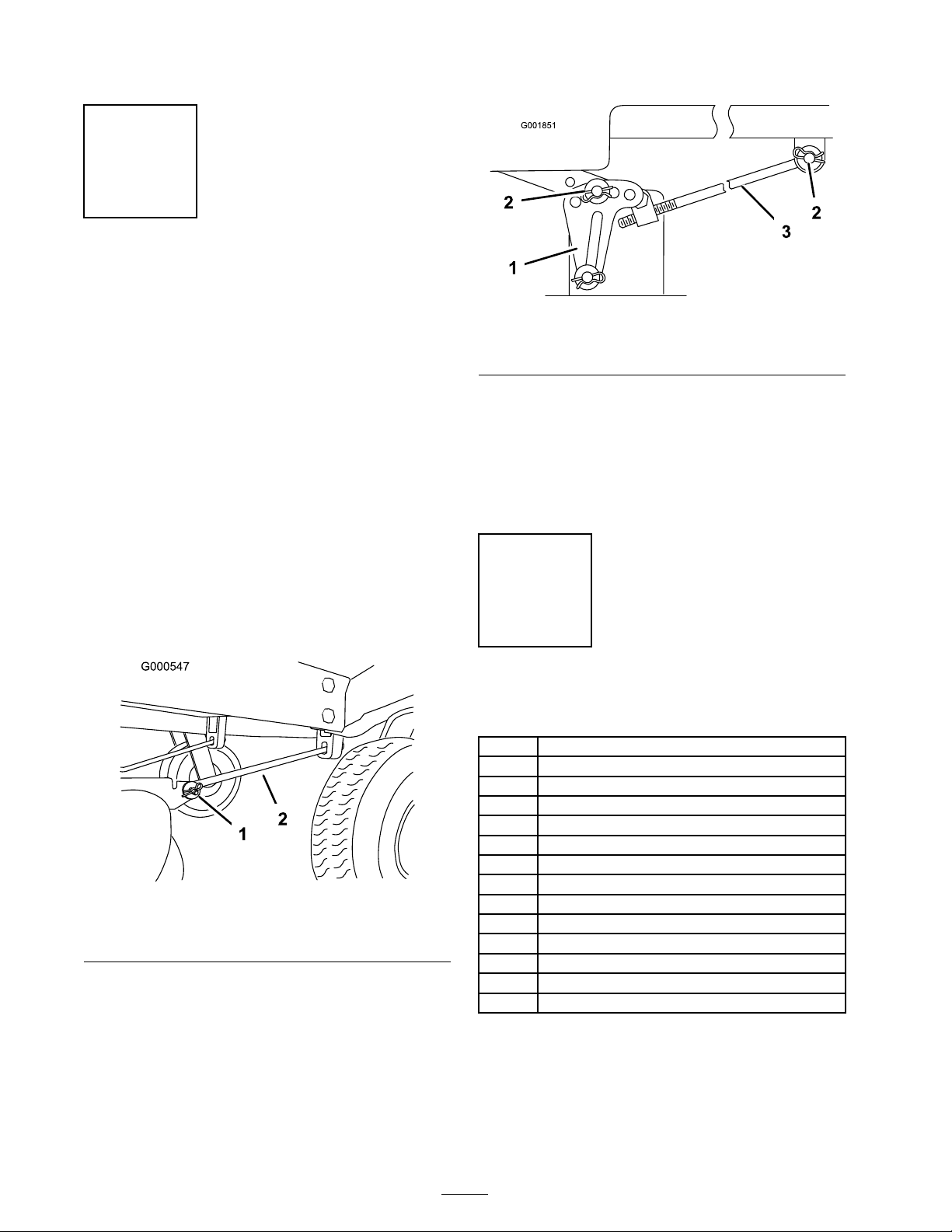
Removing the Mower
No Parts Required
Procedure
Note: Before remo ving the mo w er , mak e a note
for whic h holes are used in the lev eling brac k ets
( Figure 2 ).
1. P ark the mac hine on a lev el surface and
diseng ag e the blade control switc h.
2. Mo v e the motion control lev ers to the brak e
position, stop the engine , remo v e the k ey , and
w ait for all mo ving par ts to stop before lea ving
the operating position.
3. Lo w er the height-of-cut lev er to the lo w est
position.
4. R emo v e the hair pin cotter and clevis pin from
the front suppor t rod on eac h side of the
mo w er ( Figure 1 ).
Figure 1
1. Hairpin cotter and clevis
pin
2. Support rod
5. R emo v e the hair pin cotter and w asher from
the adjusting rod ( Figure 2 ) on eac h side of the
mo w er .
6. R emo v e the hair pin cotter and w asher at the
mo w er lev eling brac k ets ( Figure 2 ) on eac h side
of the mo w er . Note whic h hole the lev eling
brac k et is mounted in for future installation.
Slide the brac k ets off of the mounting pin.
Figure 2
1. Leveling bracket 3. Adjusting rod
2. Hairpin cotter and washer
7. Lift up the front par t of the mac hine and
suppor t the mac hine using jac k stands .
8. Slide the mo w er forw ard and out from
under neath the mac hine .
Note: R etain all par ts for future installation.
Step
2
Assembling the Blade
Parts needed for this step:
1
Blade assembly
1
Rod
2
Cotter pin (1 inch)
2
Skid
4
Carriage bolt (3/8 x 1 inch)
4
Flat washer (3/8 inch)
4
Locknut (3/8 inch)
1
Frame assembly
1
Bolt (3/4 x 3-3/4 inch)
1
Locknut (3/4 inch)
1
Index lever
1
Bolt (1/4 x 2 inch)
1
Locknut (1/4 inch)
1
Cotter pin (1-1/4 inch)
Procedure
1. Lift and rotate the c hannel assembly ( Figure
3 ) so that the holes align with the lo w er blade
mounts .
2
Page 3
2. Slide the rod through the holes and secure it
G005836
1
2
3
4
5
3
G005837
1
2,3,4
G005838
1
2
3
4
5
6
7
8
with tw o cotter pins ( Figure 3 ) (Fig . 4).
Figure 3
1. Channel assembly 4. Lower blade mounts
2. Rod 5. Upper rod
3. Cotter pin (1 inch)
5. Apply a g eneral pur pose g rease to the pi v ot
area of the frame and c hannel ( Figure 5 ).
6. Slide the blade c hannel assembly betw een the
frame mount and secure it with a bolt (3/4 x
3-3/4 inc h) and loc kn ut (3/4 inc h) ( Figure 5 ).
Note: Do not tighten the n ut and bolt
ex cessi v ely; this a v oids binding on the c hannel
w eldment as it pi v ots from side to side .
3. Bend the ends of the cotter pins to secure the
rod.
4. Attac h the skids to both sides of the blade with
1. Channel assembly 5. Index lever
2. Lubricate here
3. Bolt (3/4 x 3-3/4 inch) 7. Locknut (1/4 inch)
4. Locknut (3/4 inch) 8. Cotter pin (1-1/4 inch)
Figure 5
6. Bolt (1/4 x 2 inch)
4 car riag e bolts (3/8 x 1 inc h), flat w ashers
(3/8 inc h), and loc kn uts (3/8 inc h) ( Figure 4 ).
7. Attac h the index lev er to the frame assembly
with a bolt (1/4 x 2 inc h) and loc kn ut (1/4
inc h) ( Figure 5 ).
8. Connect the index lev er to the angle pin with a
cotter pin (1-1/4 inc h) ( Figure 5 ).
9. Bend the end of the cotter pin to secure the
lev er .
1. Skit
2. Carriage bolt (3/8 x 1 inch) 4. Locknut (3/8 inch)
Figure 4
3. Flat washer (3/8 inch)
Note: Use the slotted holes to position the
skid height according to what type of surface
y ou will be plo wing . P osition the skids lo w er
for plo wing rough surfaces or higher for
plo wing smoother surfaces .
3
Page 4

Step
G005839
1
3
Preparing the Machine
Parts needed for this step:
1
Lift assembly (CE Completion Kit)
1
Lift arm, snow blade
4
Bolt (5/16 x 3/4 inch)
4
Nut (5/16 inch)
1
Front spring mount (CE Completion Kit)
1
Extension spring
1
Rear spring mount (CE Completion Kit)
1
Bolt (1/4 x 3/4 inch)
1
Locknut (1/4 inch)
Procedure
1. Mo v e the lift lev er into the lo w est position
( Figure 6 ).
Figure 7
1. Lift assembly, existing 4. Lift lever
2. Bolt, existing 5. Lift block
3. Washer, existing
6. Nut
3. R emo v e the existing lift assembly from the
frame and re place it with the lift assembly from
the CE completion kit ( Figure 8 ). Inser t the
right side of the lift assembly into the frame
and then mo v e it into the bearing assembly on
the left side of the frame ( Figure 8 ).
Figure 6
1. Lift lever
2. R emo v e the tw o bolts , tw o w ashers , and n ut
connecting the lift lev er to the lift bloc k ( Figure
7 ).
Figure 8
1. Bolt, existing
2. Washer, existing 5. Bearing assembly, frame
3. Front spring mount
4
4. Nut, existing
6. Lift assembly, new
Page 5
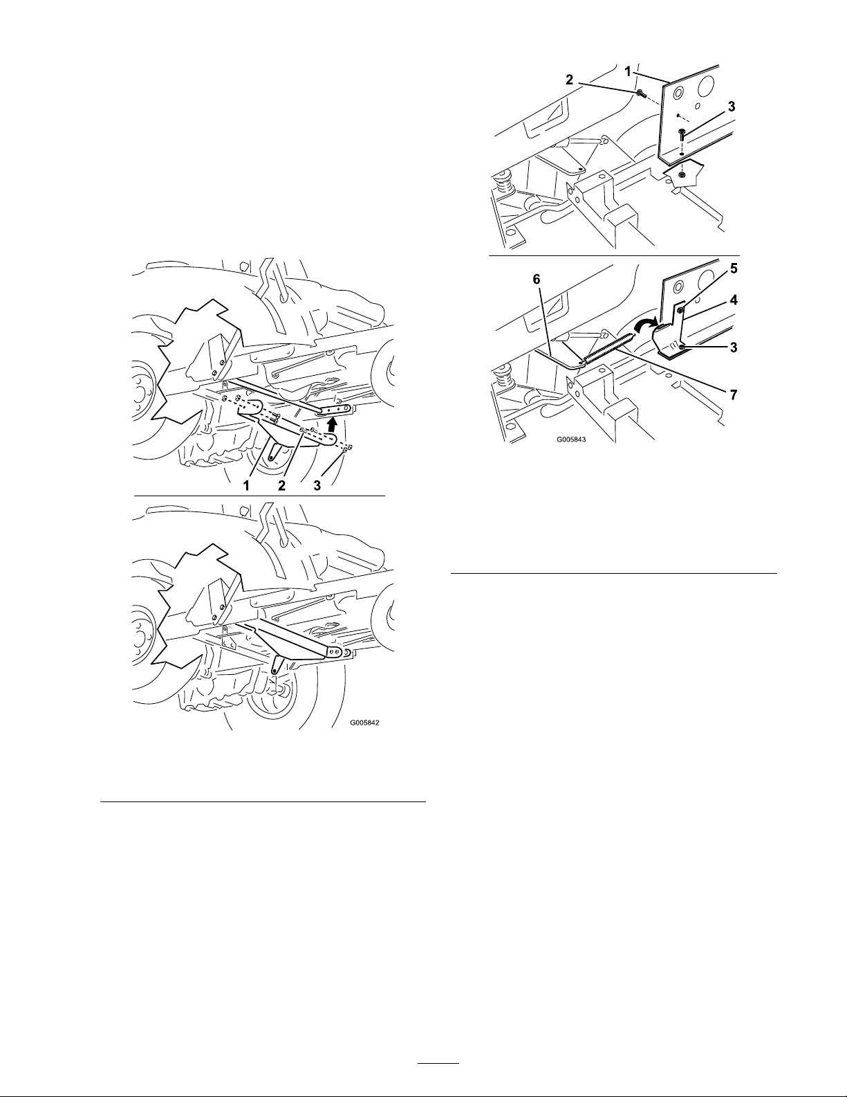
4. Attac h the front spring mount from the CE
con v ersion kit to the lift lev er and secure
the lift assembly in place using the fasteners
remo v ed in Ste p 2 ( Figure 8 ).
5. Attac h the lift ar m to the mac hine lift ar m
assembly using 4 bolts (5/16 x 3/4 inc h) and 4
n uts (5/16 inc h) as sho wn in Figure 9 .
Note: Install the n uts on the outside to
prev ent interference when operating the blade .
1. Fuel tank plate
2. Upper screw
3. Front bolt/nut
4. Rear spring mount
Figure 10
5. Bolt (1/4 x 3/4 inch) and
locknut (1/4 inch) (Locknut
shown installed on the
bolt)
6. Front spring mount
7. Spring
Figure 9
1. Lift arm
2. Bolt (5/16 x 3/4 inch)
3. Nut (5/16 inch)
6. Mo v e the seat forw ard and remo v e the batter y
to access the fuel tank plate mounted to the
tractor frame . R efer the mac hine Operator’ s
Manual for more infor mation.
7. R emo v e the front bolt and n ut in the base
of the fuel tank plate . R etain these fasteners .
R emo v e the upper screw in the fuel tank plate
and discard ( Figure 10 ).
8. Raise the lift lev er to the highest possible
position.
9. Install the rear spring mount from the CE
completion kit to the fuel tank plate using the
front bolt remo v ed previously ( Figure 10 ).
10. Secure the rear spring mount to the fuel tank
plate using a bolt (1/4 x 3/4 inc h) and loc kn ut
(1/4 inc h) ( Figure 10 ).
11. Attac h the spring to the front spring mount.
12. Lift up on the lift lev er and extend the spring
rearw ard. Attac h the loose end of the spring to
the hook on the rear spring mount ( Figure 10 ).
13. R e place the batter y and lo w er the seat bac k
into position.
5
Page 6

Step
G005844
1
2
3
4
4
Installing the Snow Blade
Parts needed for this step:
2
Side plate
1
Spacer (CE Completion Kit)
6
Bolt (3/8 x 1 inch)
3
Flat washer (3/8 inch)
6
Flange nut (3/8 inch)
1
Lift mount assembly
1
Lift rod
1
Cotter pin (3/4 inch)
3. Lift the blade assembly off the g round and
slide the frame assembly beneath the mac hine
as de picted b y the ar ro ws sho wn in Figure 12 .
Figure 12
Procedure
1. Install a side plate to the outside of the
mac hine frame on the right side using tw o
bolts (3/8 x 1 inc h), a spacer , and tw o flang e
n uts (3/8 inc h) ( Figure 11 ). Do not tighten the
fasteners at this time .
Note: T he sno w blade is in position when
the rear shaft of the frame assembly has mo v ed
past the lift ar m and is lined up with the hole
in the side plate .
4. Lift the rear shaft of the frame assembly up
and into the side plate holes ( Figure 13 ).
Figure 11
1. Side plate
2. Bolt (3/8 x 1 inch)
3. Flange nut (3/8 inch)
4. Spacer
2. Install the other side plate on the left side of
the mac hine frame on the inside using tw o
bolts (3/8 x 1 inc h) and tw o flang e n uts (3/8
inc h) as sho wn in Figure 11 . Do not tighten
1. Rear shaft, snow blade
assembly
Figure 13
2. Hole, side plate
the fasteners at this time .
6
Page 7
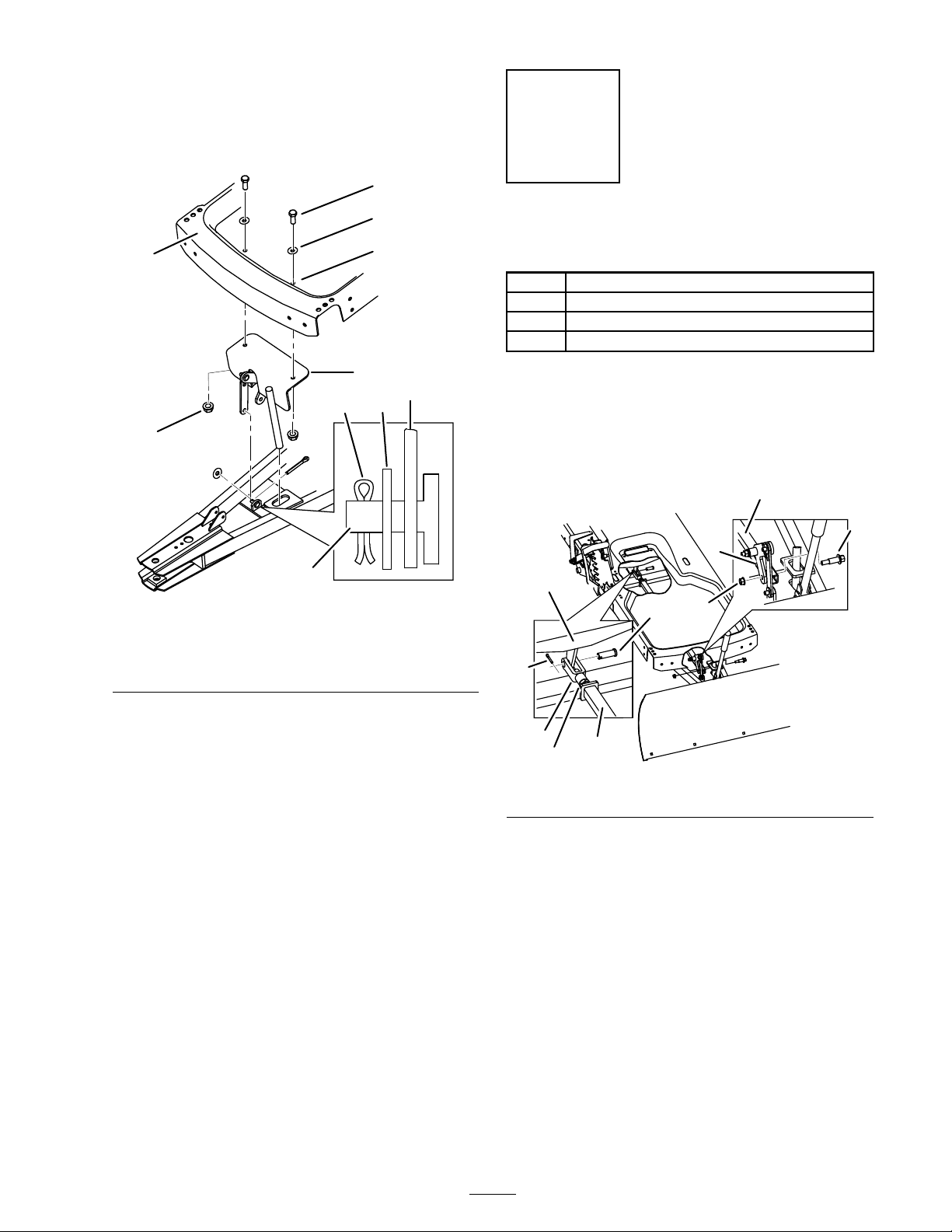
5. T or que all the side plate bolts to 30 ft-lb (41
G005846
1
2
3
4
5
6
7
8
9
10
G005847
1
2
3
4
5
6
7
8
9
1
N ⋅ m).
6. R emo v e the foot plate to access the existing
holes in the mac hine frame ( Figure 14 ).
Step
5
Connecting the Lift Rod
Parts needed for this step:
1
Clevis pin
1
Cotter pin (3/4 inch)
1
Shoulder bolt
1
Flange nut (3/8 inch)
Procedure
1. Mo v e the lift rod into position beneath the
mac hine and abo v e the frame assembly ( Figure
15 ).
Figure 14
1.
7. Install the lift mount assembly using tw o bolts
(3/8 x 1 inc h), tw o w ashers (3/8 inc h) and tw o
flang e n uts (3/8 inc h) as sho wn in Figure 14 .
Note: Mo v e the lift mount assembly into
position from the side of the unit in order to
install it in the cor rect orientation.
8. Place the link lift o v er the frame assembly post
and use a w asher (3/8 inc h) and cotter pin (3/4
inc h) to hold it in place ( Figure 14 ).
9. Bend the end of the cotter pin to secure the
lift link.
2. Attac h the lift rod to the pi v ot ar m of the lift
mount using the shoulder bolt and flang e n ut
(3/8 inc h) as sho wn in Figure 15 .
3. Line up the holes in the lift rod y ok e and the
lift ar m ( Figure 15 ).
Note: If needed, adjust the length of the lift
rod ar m b y loosening the jam n ut and tur n the
y ok e to either lengthen or shor ten the lift rod.
4. Set the blade height to ensure the full rang e of
motion with the lift lev er . R efer to Setting the
Blade Height in the Operator’ s Manual .
Figure 15
7
Page 8

5. Install the lift rod to the lift ar m using a clevis
pin and cotter pin (3/4 inc h) as sho wn in
Figure 15 .
6. Bend the ends of the cotter pins to secure the
clevis pin.
8
 Loading...