

Page 1

TimeCutter® ZD Riding Mower
Model No. All Models
Loose Parts
Use the chart below to verify that all parts have been shipped.
Form No. 3357-921 Rev A
Setup Instructions
Step
1
2
3
4
No parts required
Retainer clip
Screw, self-tapping (10 x 1/2 inch)
Collection bag
DFS lever
Washer
Cotter pin
Ignition Key
Operator’s Manual
Engine Operator’s Manual
Description
Qty.
–
2
4
1
1
1
1
1
1
1
Charge the battery.
Install the bag clips.
Install the collection bag.
Complete the Setup.
Note: Deter mine the left and right sides of the mac hine from the nor mal operating position.
Step
Batter y electr ol yte contains sulfuric acid
1
Charging the Battery
No Parts Required
which is a deadl y poison and causes sev er e
bur ns.
• Do not drink electr ol yte and a v oid
contact with skin, ey es or clothing . W ear
safety g lasses to shield y our ey es and
r ob ber g lo v es to pr otect y our hands.
Use
Procedure
Bulk electrolyte with 1.260 specific g ra vity m ust be
purc hased from a local batter y supply outlet.
© 2007—The Toro® Company
8111 Lyndale Avenue South
Bloomington, MN 55420
Register at www.Toro.com. Original Instructions (EN)
• Fill the batter y wher e clean w ater is
al w ays a v aila ble f or flushing the skin.
• F ollo w all instr uctions and compl y with
all safety messa ges on the electr ol yte
container .
1. Raise the seat to access the batter y .
2. R emo v e the batter y from the mac hine and
place it on a lev el surface; refer to the Operator’ s
Manual , R emo ving the Batter y .
Important: Nev er fill the batter y with
electr ol yte while the batter y is installed in
the tractor . Electr ol yte could be spilled on
other par ts and cause cor r osion.
3. Clean the top of the batter y with a paper to w el.
Printed in the USA.
All Rights Reserved
Page 2
4. R emo v e the v ent caps from the batter y
( Figure 1 ). Slo wly pour electrolyte into eac h
batter y cell until the electrolyte lev el is up to
the Upper line on the batter y case ( Figure 1 ).
Important: Do not o v erfill the batter y
because electr ol yte (sulfuric acid) can
cause sev er e cor r osion and dama ge to the
chassis.
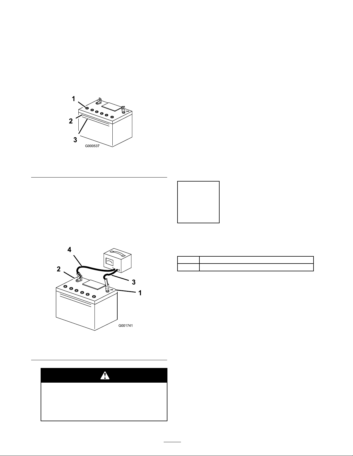
Figure 1
1. Vent caps
2. Upper line
3. Lower line
8. Charg e the batter y for 10 to 15 min utes at
25 to 30 amps or 30 min utes at 4 to 6 amps
( Figure 2 ). Do not o v erc harg e the batter y .
9. W hen finished, unplug the c harg er from the
electrical outlet, then disconnect the c harg er
leads from the batter y posts ( Figure 2 ).
Note: Do not r un the mac hine with the
batter y disconnected, electrical damag e ma y
occur .
10. Install the batter y to the mac hine; refer to the
Operator’ s Manual , Installing the Batter y .
11. Connect the positi v e batter y cable to the
positi v e batter y post using the existing
fasteners .
12. Connect the neg ati v e batter y cable to the
neg ati v e batter y post using the existing
fasteners .
5. W ait fiv e to ten min utes after filling the
batter y cells . Add electrolyte , if necessar y , until
the electrolyte lev el is up to the Upper line
( Figure 1 ) on the batter y case .
6. Install the batter y v ent caps .
7. Connect the c harg er leads to the cor responding
batter y posts as sho wn in Figure 2 .
Figure 2
1. Positive Battery Post
2. Negative Battery Post
3. Red (+) Charger Lead
4. Black (-) Charger Lead
Step
2
Installing the Bag Clips
Parts needed for this step:
2
Retainer clip
4
Screw, self-tapping (10 x 1/2 inch)
Procedure
1. Locate the bag clips and self taping screws in
loose par ts .
2. Install a bag clip to eac h side of the heat shield
as sho wn in Figure 3 . Install the clips to the
bac kside of the heat shield at the holes so the
contour of the clips matc h the contour of the
shield.
Charging the batter y pr oduces gasses
that can explode.
Nev er smok e near the batter y and k eep
spar ks and flames a w ay fr om batter y .
2
Page 3

4
G005848
1
2
3
4
5
6
Figure 3
G005849
1
2
3
4
1. Bag clip 4. Holes, existing
2. Screw
3. Heat shield, backside 6. Bag clip, installed
5. Heat shield
3. R e peat this procedure for the remaining clip
on the opposing side of the heat shield.
Step
3
Installing the Collection Bag
Parts needed for this step:
1
Collection bag
1
DFS lever
1
Washer
1
Cotter pin
Procedure
1. R emo v e the DFS lev er and collection bag from
the pac kaging .
Figure 4
1. DFS lever 3. Washer
2. Collection bag
4. Cotter pin
3. Install a w asher o v er the end of the DFS lev er
inside the collection bag ( Figure 4 ).
4. Secure the lev er assembly with a cotter pin and
bend the ends to hold it place ( Figure 4 ).
5. Install the collection bag to the mac hine
( Figure 5 ). Install the lev er side pin in the
collection bag into the retaining hole in the
notc h of the engine co v er . Seat the opposing
pin into the other notc h in the engine co v er
and allo w the collection bag swing do wn into
place .
2. Install the DFS lev er into the opening on the
top of the collection bag Figure 4 .
Figure 5
1. Collection bag 3. Retaining hole
2. Engine cover
4. Pin, lever side
3
Page 4

Step
4
Completing the Setup
Parts needed for this step:
1
Ignition Key
1
Operator’s Manual
1
Engine Operator’s Manual
Procedure
Checking the Tir e Pr essur e
Chec k the front and rear tires for proper inflation.
R efer to Chec king the Tire Pressure in the Operator’ s
Manual for the recommended inflation pressure .
Checking the Mo w er Adjustment
T he mo w er dec k w as lev eled at the factor y . If the
mo w er is not cutting lev el, adjust the side-to-side
lev el and the front-to-rear blade slope . See the
Operator’ s Man ual for the proper procedure .
Checking the Engine Oil Lev el
Before y ou star t the engine and use the mac hine ,
c hec k the oil lev el in the engine crankcase; refer to
Chec king the Oil Lev el in the Operator’ s Manual .
R eview the R emaining P ar ts
K ee p all the follo wing items with the mac hine:
• Ignition K ey
• Operator’ s Manual
• Engine Operator’ s Manual
4
 Loading...