

Page 1

TimeCutter® Riding Mower
Model No. All models
Loose Parts
Use the chart below to verify that all parts have been shipped.
Form No. 3356-867 Rev A
Setup Instructions
Step
1
2
3
4
5
No parts required
Bolt (1/4 x 3/4 inch)
Washer
Nut (1/4 inch)
Seat
Spacers 2
Flat washers
Knobs
Control lever
Bolt (1/4 x 3/4 inch)
Ignition Key
Operator’s Manual
Engine Operator’s Manual
Hose coupling
Operator Training Material
Description
Note: Deter mine the left and right sides of the
mac hine from the nor mal operating position.
Qty.
–
2
2
2
1
2
2
2
4
1
1
1
1
1
Charge the battery.
Connect the battery.
Install the seat.
Install the motion control levers.
Complete thesetup.
Use
© 2006—The Toro® Company
8111 Lyndale Avenue South
Bloomington, MN 55420
Register at www.Toro.com. Original Instructions (EN)
Printed in the USA.
All Rights Reserved
Page 2
Step
1
Charging the Battery
No Parts Required
Procedure
Warning
CALIFORNIA
Pr oposition 65 W ar ning
Batter y posts, ter minals, and r elated
accessories contain lead and lead
compounds, chemicals kno wn to the State of
Calif or nia to cause cancer and r epr oducti v e
har m. W ash hands after handling .
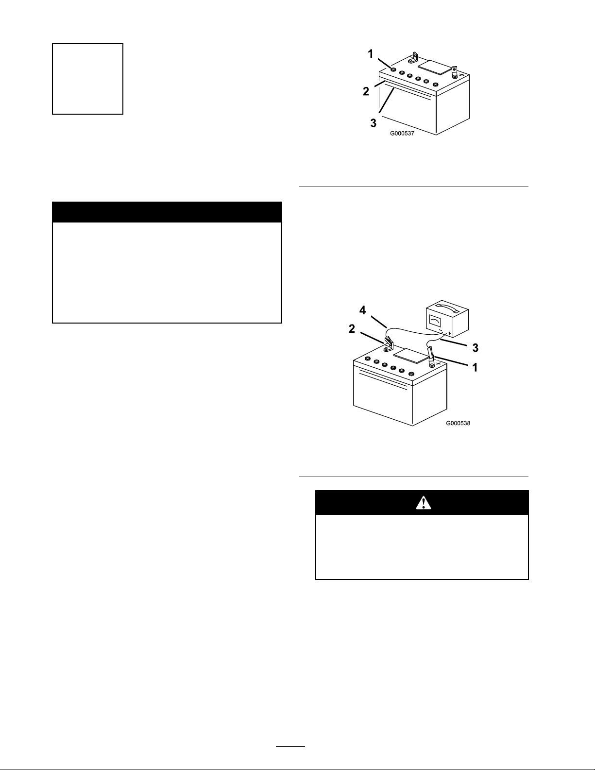
Figure 1
1. Vent caps
2. Upper line
4. W ait fiv e to ten min utes after filling the
batter y cells . Add electrolyte , if necessar y , until
the electrolyte lev el is up to the Upper line
( Figure 1 ) on the batter y case .
5. Install the batter y v ent caps .
6. Connect the c harg er leads to the cor responding
batter y posts as sho wn in Figure 2 .
3. Lower line
Bulk electrolyte with 1.260 specific g ra vity m ust be
purc hased from a local batter y supply outlet.
1. Raise the seat to access the batter y . R emo v e
the batter y from the mac hine and place it on
a lev el surface; refer to the Operator’ s Manual ,
R emo ving the Batter y .
Important: Nev er fill the batter y with
electr ol yte while the batter y is installed in
the tractor . Electr ol yte could be spilled on
other par ts and cause cor r osion.
2. Clean the top of the batter y with a paper to w el.
3. R emo v e the v ent caps from the batter y
( Figure 1 ). Slo wly pour electrolyte into eac h
batter y cell until the electrolyte lev el is up to
the Upper line on the batter y case ( Figure 1 ).
Important: Do not o v erfill the batter y
because electr ol yte (sulfuric acid) can
cause sev er e cor r osion and dama ge to the
chassis.
Figure 2
1. Positive Battery Post
2. Negative Battery Post
Charging the batter y pr oduces gasses
that can explode.
Nev er smok e near the batter y and k eep
spar ks and flames a w ay fr om batter y .
7. Charg e the batter y for 10 to 15 min utes at
25 to 30 amps or 30 min utes at 4 to 6 amps
( Figure 2 ). Do not o v erc harg e the batter y .
3. Red (+) Charger Lead
4. Black (-) Charger Lead
8. W hen finished, unplug the c harg er from the
electrical outlet, then disconnect the c harg er
leads from the batter y posts ( Figure 2 ).
Note: Do not r un the mac hine with the
batter y disconnected, electrical damag e ma y
occur .
2
Page 3
Step
2
Connecting the Battery
Parts needed for this step:
2
Bolt (1/4 x 3/4 inch)
2
Washer
2
Nut (1/4 inch)
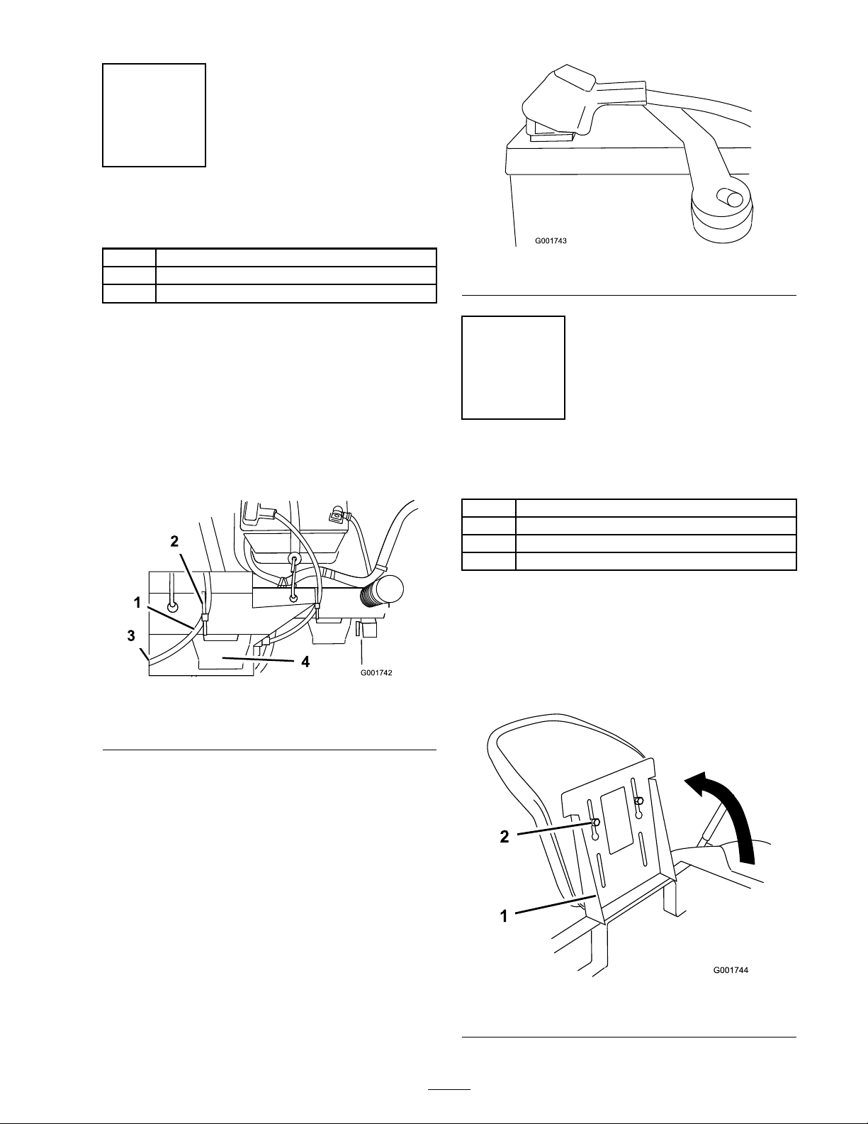
Figure 4
Procedure
1. Install the batter y in the mac hine and connect
the batter y cables using tw o bolts (1/4 x 3/4
inc h), tw o w ashers , and tw o n uts (1/4 inc h).
R oute the batter y cable from the positi v e
batter y post to the solenoid. Ensure the cable
is routed abo v e the crossbar and betw een the
seat suppor ts as sho wn in Figure 3 .
Figure 3
1. Battery cable 3. To solenoid
2. Plastic tie 4. Fuse block
Step
3
Installing the Seat
Parts needed for this step:
1
Seat
2 Spacers
2
Flat washers
2
Knobs
Procedure
1. R emo v e the seat from the mac hine . Raise the
seat suppor t on the mac hine ( Figure 5 ).
2. Slide the shoulder bolts on the bottom of the
seat into the slots in the seat suppor t ( Figure 5 ).
2. Connect the positi v e batter y cable to the
positi v e batter y post using the existing
fasteners .
Important: Connect the ca ble to the
positi v e post so that it extends parallel with
the top of the batter y , as sho wn in Figur e 4 ,
and v erify that it does not come in contact
with the seat pan.
Figure 5
1. Seat support
3
2. Shoulder bolt
Page 4

3. Secure the seat to the seat suppor t with the
spacers , flat w ashers (5/16 inc h) and knobs
( Figure 6 ).
Figure 6
1. Seat
2. Seat support 5. Spacer
3. Knob
4. Washers (5/16 inch)
Step
4
Installing the Motion
Control Levers
Parts needed for this step:
2
Control lever
4
Bolt (1/4 x 3/4 inch)
Procedure
1. R emo v e the motion control lev ers from the
mac hine .
2. P osition the control lev er to the desired height
and align with the holes in the control lev er
shaft ( Figure 8 ).
Important: Mak e sur e the spacer s
ar e betw een the seat and suppor t, and
the knobs pass thr ough the w asher s,
seat suppor t, spacer s and into the seat
( Figur e 6 ).
4. Connect the seat switc h har ness to the seat
switc h in the base of the seat as sho wn in
Figure 7 .
3. Install 2 bolts (1/4 x 3/4 inc h) into the control
lev er and shaft ( Figure 8 ).
Figure 8
1. Control lever
2. Bolt
3.
4. R e peat the installation for the opposite control
lev er .
5. Lo w er the seat and adjust if necessar y; refer to
P ositioning the Seat in the Operator’ s Manual .
Figure 7
1. Seat
2. Seat switch
3. Switch harness
5. Lo w er the seat and adjust it if necessar y; refer
to P ositioning the Seat in the mo w er Operator’ s
Manual .
4
Page 5

Step
5
Completing the Setup
Parts needed for this step:
1
Ignition Key
1
Operator’s Manual
1
Engine Operator’s Manual
1
Hose coupling
1
Operator Training Material
Procedure
Checking the Tir e Pr essur e
Chec k the front and rear tires for proper inflation.
R efer to Chec king the Tire Pressure in the Operator’ s
Manual for the recommended inflation pressure .
Checking the Mo w er Adjustment
T he mo w er dec k w as lev eled at the factor y . If the
mo w er is not cutting lev el, adjust the side-to-side
lev el and the front-to-rear blade slope . See the
Operator’ s Man ual for the proper procedure .
Checking the Side Discharge Chute
R emo v e the pac king restraint holding the side
disc harg e c hute up and lo w er the c hute into place .
Checking the Engine Oil Lev el
Before y ou star t the engine and use the mac hine ,
c hec k the oil lev el in the engine crankcase; refer to
Chec king the Oil Lev el in the Operator’ s Manual .
R eview the R emaining P ar ts
K ee p all the follo wing items with the mac hine:
• Ignition K ey
• Operator’ s Manual
• Engine Operator’ s Manual
• Hose coupling
• View the Operator training material.
5
Page 6

Page 7

Page 8

 Loading...