

Page 1

LCE Products
Z Master Z400
Series
Service Manual
Page 2

ABOUT THIS MANUAL
This service manual was written expressly for Toro service technicians. The Toro Company has
made every effort to make the information in this manual complete and correct.
Basic shop safety knowledge and mechanical/electrical skills are assumed. The Table of Contents
lists the systems and the related topics covered in this manual.
The following service materials are available in addition to this service manual:
Hydrostatic Pumps: Hydro-Gear BDP-10A/16A/21L - Service and Repair Manual
Form #492-4789
Wheel Motors: Parker/Ross Wheel Motor Service Manual
Form #492-4753
Diesel Engine: Briggs & Stratton Daihatsu 3 Cylinder Liquid-Cooled Engine Repair Manual
Form #492-0670
Hydraulic Troubleshooting: Interactive hydraulic troubleshooting and failure analysis on compact disk
Form #492-4777
Electrical Troubleshooting: Interactive electrical troubleshooting and wiring diagrams on compact disk
Form # 492-9143
The Z Master 597 model years 2004 and 2005 are covered in this manual. The manual may also
be specied for use on later model products.
The hydrostatic drive system is precision machinery. Maintain strict cleanliness control during all
stages of service and repair. Cover or cap all hose ends and ttings whenever they are exposed.
Even a small amount of dirt or other contamination can severely damage the system.
We are hopeful that you will nd this manual a valuable addition to your service shop. If you have
any questions or comments regarding this manual, please contact us at the following address:
The Toro Company
LCE Service Training Department
8111 Lyndale Avenue South
Bloomington, MN 55420
The Toro Company reserves the right to change product specications or this manual without
notice.
Copyright© All Rights Reserved
©2006 The Toro Company
Page 3

THIS PAGE INTENTIONALLY LEFT BLANK.
Page 4

TABLE OF CONTENTS
Safety Information
General Information . . . . . . . . . . . . . . . . . . . . . . . . . . . . . . . . . .
Think Safety First . . . . . . . . . . . . . . . . . . . . . . . . . . . . . . . . . . .
Specications
Machine Prole Photos
Z 400 Estate Series 19 hp Kawasaki OHV V-Twin . . . . . . . . . . . . . . . . . . . .
Z 400 Estate Series 18 hp Kohler . . . . . . . . . . . . . . . . . . . . . . . . . . .
Z 450 Pro Performance Series 20 hp Kohler OHV V-Twin . . . . . . . . . . . . . . . . .
Z 100 Series 19 hp Kawasaki KAI OHV V-Twin . . . . . . . . . . . . . . . . . . . . .
Z 450 Pro Performance Series 23 hp Kawasaki OHV V-Twin . . . . . . . . . . . . . . . .
Z 440 Pro Value Series 19 hp Kawasaki KAI OHV V-Twin . . . . . . . . . . . . . . . . .
Engine Specications . . . . . . . . . . . . . . . . . . . . . . . . . . . . . . . . .
Z 400 Series Manual Specications . . . . . . . . . . . . . . . . . . . . . . . . . . .
Fuel System . . . . . . . . . . . . . . . . . . . . . . . . . . . . . . . . . . . . .
Traction System . . . . . . . . . . . . . . . . . . . . . . . . . . . . . . . . . . .
Deck Drive . . . . . . . . . . . . . . . . . . . . . . . . . . . . . . . . . . . . .
Tires . . . . . . . . . . . . . . . . . . . . . . . . . . . . . . . . . . . . . . . .
Electrical System . . . . . . . . . . . . . . . . . . . . . . . . . . . . . . . . . . .
Cutting Decks . . . . . . . . . . . . . . . . . . . . . . . . . . . . . . . . . . . .
Cutting Decks continued . . . . . . . . . . . . . . . . . . . . . . . . . . . . . . . .
Lubrication Fittings . . . . . . . . . . . . . . . . . . . . . . . . . . . . . . . . . .
General Specications . . . . . . . . . . . . . . . . . . . . . . . . . . . . . . . . .
Service Aid Decals . . . . . . . . . . . . . . . . . . . . . . . . . . . . . . . . . .
Available Service Manuals / Service Aids . . . . . . . . . . . . . . . . . . . . . . . . .
Torque Specications . . . . . . . . . . . . . . . . . . . . . . . . . . . . . . . . .
Standard Torque for Dry, Zinc Plated, and Steel Fasteners (Inch Series) . . . . . . . . . . . . .
Standard Torque for Dry, Zinc, and Steel Fasteners (Metric Fasteners) . . . . . . . . . . . . . .
Other Torque Specications . . . . . . . . . . . . . . . . . . . . . . . . . . . . . . .
Equivalents and Conversions . . . . . . . . . . . . . . . . . . . . . . . . . . . . . .
U.S. to Metric Conversions . . . . . . . . . . . . . . . . . . . . . . . . . . . . . . .
1-2
1-2
2-2
2-3
2-4
2-5
2-6
2-7
2-8
2-9
2-9
2-9
2-10
2-10
2-10
2-11
2-12
2-13
2-13
2-13
2-15
2-16
2-17
2-18
2-19
2-20
2-21
Chassis
Caster Fork Assembly Removal Estate Series with bushing front casters . . . . . . . . . . . . .
Caster Fork Assembly Installation Estate Series with bushing front casters . . . . . . . . . . . .
Caster Fork Assembly Removal Pro 100/400 Series with tapered roller front casters . . . . . . . .
Caster Fork Assembly Installation Pro 100/400 Series with tapered roller front casters . . . . . . . .
Front Wheel Removal and Bearing Replacement Estate Series . . . . . . . . . . . . . . . . .
Pro 100/400 Series with tapered roller front casters . . . . . . . . . . . . . . . . . . . .
Fuel Tank Removal
Left Side Fuel Tank Removal . . . . . . . . . . . . . . . . . . . . . . . . . . . .
Left Side Fuel Tank Installation . . . . . . . . . . . . . . . . . . . . . . . . . . . .
Right Side Fuel Tank Removal and Installation . . . . . . . . . . . . . . . . . . . . . .
Fuel Check Valve
Purpose . . . . . . . . . . . . . . . . . . . . . . . . . . . . . . . . . . . . .
Location . . . . . . . . . . . . . . . . . . . . . . . . . . . . . . . . . . . . .
Proper Installation . . . . . . . . . . . . . . . . . . . . . . . . . . . . . . . . .
Fuel Shut Off Valve
Purpose . . . . . . . . . . . . . . . . . . . . . . . . . . . . . . . . . . . . .
Location . . . . . . . . . . . . . . . . . . . . . . . . . . . . . . . . . . . . .
Pro 400 Series V-Twin Kohler . . . . . . . . . . . . . . . . . . . . . . . . . . . .
Proper Installation . . . . . . . . . . . . . . . . . . . . . . . . . . . . . . . . .
3-2
3-3
3-4
3-6
3-8
3-12
3-14
3-16
3-16
3-16
3-16
3-16
3-17
3-17
3-17
3-17
iZ Master Z400 Service Manual
Page 5

TABLE OF CONTENTS
Chassis continued
Parking Brake Handle/Shaft Assembly Removal All models . . . . . . . . . . . . . . . . . .
Parking Brake Handle/Shaft Assembly Installation All models . . . . . . . . . . . . . . . . .
Brake Bar Removal (Estate Series) . . . . . . . . . . . . . . . . . . . . . . . . . . . .
Brake Installation . . . . . . . . . . . . . . . . . . . . . . . . . . . . . . . . . . .
Adjusting the Parking Brake . . . . . . . . . . . . . . . . . . . . . . . . . . . . . .
Brake Band Removal (Pro Series) . . . . . . . . . . . . . . . . . . . . . . . . . . . .
Brake Band Installation . . . . . . . . . . . . . . . . . . . . . . . . . . . . . . . .
Brake Shaft Removal (Pro Series) . . . . . . . . . . . . . . . . . . . . . . . . . . . .
Brake Shaft Installation . . . . . . . . . . . . . . . . . . . . . . . . . . . . . . . .
Deck Lift Lever Removal . . . . . . . . . . . . . . . . . . . . . . . . . . . . . . . .
Deck Lift Lever Installation . . . . . . . . . . . . . . . . . . . . . . . . . . . . . . .
Motion Control Assembly Removal . . . . . . . . . . . . . . . . . . . . . . . . . . . .
Motion Control Assembly Installation . . . . . . . . . . . . . . . . . . . . . . . . . . .
Hydraulic System
Hydrostatic Pump Removal . . . . . . . . . . . . . . . . . . . . . . . . . . . . . . .
Hydrostatic Pump Installation . . . . . . . . . . . . . . . . . . . . . . . . . . . . . .
Replacing the Pump Drive Belt . . . . . . . . . . . . . . . . . . . . . . . . . . . . .
Installing the Pump Drive Belt . . . . . . . . . . . . . . . . . . . . . . . . . . . . . .
Idler Arm Removal . . . . . . . . . . . . . . . . . . . . . . . . . . . . . . . . . .
Idler Arm Install . . . . . . . . . . . . . . . . . . . . . . . . . . . . . . . . . . .
Wheel Motor Removal . . . . . . . . . . . . . . . . . . . . . . . . . . . . . . . . .
Wheel Motor Installation . . . . . . . . . . . . . . . . . . . . . . . . . . . . . . . .
Adjusting the Handle Neutral . . . . . . . . . . . . . . . . . . . . . . . . . . . . . .
Setting the Hydraulic Pump Neutral . . . . . . . . . . . . . . . . . . . . . . . . . . . .
Setting the LH Hydraulic Pump Neutral . . . . . . . . . . . . . . . . . . . . . . . . . .
Setting the RH Hydraulic Pump Neutral . . . . . . . . . . . . . . . . . . . . . . . . . .
Adjusting the Tracking . . . . . . . . . . . . . . . . . . . . . . . . . . . . . . . . .
Purging the Hydraulic System . . . . . . . . . . . . . . . . . . . . . . . . . . . . . .
Hydraulic Flow Testing Procedure . . . . . . . . . . . . . . . . . . . . . . . . . . . .
Pushing the Machine by Hand . . . . . . . . . . . . . . . . . . . . . . . . . . . . . .
Changing to Machine Operation . . . . . . . . . . . . . . . . . . . . . . . . . . . . .
3-18
3-20
3-20
3-21
3-21
3-22
3-23
3-23
3-25
3-25
3-28
3-31
3-33
4-2
4-4
4-7
4-9
4-9
4-10
4-10
4-12
4-13
4-14
4-15
4-16
4-17
4-18
4-18
4-21
4-21
Engine
Kawasaki FH580V 19 hp Engine Removal . . . . . . . . . . . . . . . . . . . . . . . . .
Kawasaki FH580V 19 hp Engine Installation . . . . . . . . . . . . . . . . . . . . . . . .
Kohler V-Twin 20 hp Engine Removal . . . . . . . . . . . . . . . . . . . . . . . . . . .
Kohler V-Twin 20 hp Engine Install . . . . . . . . . . . . . . . . . . . . . . . . . . . .
Kohler 18 hp Single Cylinder Removal . . . . . . . . . . . . . . . . . . . . . . . . . .
Kohler 18 hp Single Cylinder Install . . . . . . . . . . . . . . . . . . . . . . . . . . .
Z 100 Series FH580V (KAI) 19 hp Kawasaki Removal . . . . . . . . . . . . . . . . . . . .
Z 100 Series FH580V (KAI) 19 hp Kawasaki Install . . . . . . . . . . . . . . . . . . . . .
Electrical
General . . . . . . . . . . . . . . . . . . . . . . . . . . . . . . . . . . . . . .
Relays . . . . . . . . . . . . . . . . . . . . . . . . . . . . . . . . . . . . . . .
PTO Switch . . . . . . . . . . . . . . . . . . . . . . . . . . . . . . . . . . . . .
Ignition Switch . . . . . . . . . . . . . . . . . . . . . . . . . . . . . . . . . . . .
Neutral Safety Switch . . . . . . . . . . . . . . . . . . . . . . . . . . . . . . . . .
Park Brake Switch . . . . . . . . . . . . . . . . . . . . . . . . . . . . . . . . . .
Seat Switch . . . . . . . . . . . . . . . . . . . . . . . . . . . . . . . . . . . . .
ii Z Master Z400 Service Manual
5-2
5-6
5-12
5-18
5-24
5-28
5-34
5-39
6-2
6-2
6-3
6-5
6-6
6-7
6-8
Page 6

TABLE OF CONTENTS
Electrical continued
Seat Delay Module . . . . . . . . . . . . . . . . . . . . . . . . . . . . . . . . . .
Hour Meter . . . . . . . . . . . . . . . . . . . . . . . . . . . . . . . . . . . . .
Electric PTO Clutch . . . . . . . . . . . . . . . . . . . . . . . . . . . . . . . . . .
Coil Resistance Measurement . . . . . . . . . . . . . . . . . . . . . . . . . . . .
Measuring Clutch Current Draw . . . . . . . . . . . . . . . . . . . . . . . . . . .
Solenoid . . . . . . . . . . . . . . . . . . . . . . . . . . . . . . . . . . . . . .
Fuse Block . . . . . . . . . . . . . . . . . . . . . . . . . . . . . . . . . . . . .
Electrical Schematics
74412 . . . . . . . . . . . . . . . . . . . . . . . . . . . . . . . . . . . . .
74410 . . . . . . . . . . . . . . . . . . . . . . . . . . . . . . . . . . . . .
74411 . . . . . . . . . . . . . . . . . . . . . . . . . . . . . . . . . . . . .
74413 and 74415 . . . . . . . . . . . . . . . . . . . . . . . . . . . . . . . . .
74414 . . . . . . . . . . . . . . . . . . . . . . . . . . . . . . . . . . . . .
74416 and 74417 . . . . . . . . . . . . . . . . . . . . . . . . . . . . . . . . .
74411TE . . . . . . . . . . . . . . . . . . . . . . . . . . . . . . . . . . . .
74416TE . . . . . . . . . . . . . . . . . . . . . . . . . . . . . . . . . . . .
Mower Decks
Mower Deck Removal Estate Series . . . . . . . . . . . . . . . . . . . . . . . . . . .
Mower Deck Installation Estate Series . . . . . . . . . . . . . . . . . . . . . . . . . .
Mower Deck Removal Z 400 Series (48” and 50” Decks) . . . . . . . . . . . . . . . . . . .
Mower Deck Installation Z 400 Series (48” and 50” Decks) . . . . . . . . . . . . . . . . . .
Mower Deck Removal Z 100 Series (44” Deck) . . . . . . . . . . . . . . . . . . . . . . .
Mower Deck Installation Z 100 Series (44” Deck) . . . . . . . . . . . . . . . . . . . . . .
Mower Spindle Removal Pro 100 Series . . . . . . . . . . . . . . . . . . . . . . . . . .
Mower Spindle Installation Pro 100 Series . . . . . . . . . . . . . . . . . . . . . . . . .
Mower Spindle Removal Estate Series & Pro 400 Series . . . . . . . . . . . . . . . . . . .
Mower Spindle Installation Estate Series & Pro 400 Series . . . . . . . . . . . . . . . . . .
Mower Spindle Disassembly Estate Series & Pro 400 Series . . . . . . . . . . . . . . . . . .
Mower Spindle Assembly Estate Series & Pro 400 Series . . . . . . . . . . . . . . . . . . .
Mower Spindle Disassembly Z 100 Series (44” Deck) . . . . . . . . . . . . . . . . . . . .
Mower Spindle Assembly Z 100 Series (44” Deck) . . . . . . . . . . . . . . . . . . . . . .
Replacing the Mower Deck Drive Belt All Z 400 models . . . . . . . . . . . . . . . . . . . .
Replacing the Mower Deck Drive Belt Z 100 Series . . . . . . . . . . . . . . . . . . . . .
Adjusting the Mower Belt Tension Z 100 Series . . . . . . . . . . . . . . . . . . . . . . .
Adjusting the Mower Belt Tension Z 400 Series . . . . . . . . . . . . . . . . . . . . . . .
Leveling the Mower at 3 Positions . . . . . . . . . . . . . . . . . . . . . . . . . . . .
Setting up the Machine All models . . . . . . . . . . . . . . . . . . . . . . . . . .
Leveling the Mower Side-to-Side . . . . . . . . . . . . . . . . . . . . . . . . . . .
Adjusting the Front-to-Rear Mower Pitch . . . . . . . . . . . . . . . . . . . . . . . .
Adjusting the Compression Spring . . . . . . . . . . . . . . . . . . . . . . . . . .
6-9
6-11
6-12
6-12
6-13
6-13
6-15
6-16
6-17
6-18
6-19
6-20
6-21
6-22
6-23
7-2
7-4
7-6
7-8
7-10
7-12
7-15
7-16
7-16
7-18
7-18
7-20
7-23
7-24
7-24
7-26
7-27
7-28
7-29
7-29
7-30
7-31
iiiZ Master Z400 Service Manual
Page 7

TABLE OF CONTENTS
THIS PAGE INTENTIONALLY LEFT BLANK.
iv Z Master Z400 Service Manual
Page 8

SAFETY INFORMATION
Safety Information . . . . . . . . .
Specications . . . . . . . . . . .
Chassis . . . . . . . . . . . . . .
Hydraulic System . . . . . . . . .
Engine . . . . . . . . . . . . . . .
1
2
3
4
5
Electrical . . . . . . . . . . . . . .
Mower Decks . . . . . . . . . . .
1-1Z Master Z400 Service Manual
6
7
Page 9

SAFETY INFORMATION
SAFETY INFORMATION
General Information
This symbol means WARNING or
PERSONAL SAFETY INSTRUCTION
- read the instruction because it has to
do with your safety. Failure to comply
with the instruction may result in
personal injury or even death.
This manual is intended as a service and repair
manual only. The safety instructions provided herein
are for troubleshooting, service, and repair of the
Z Master Z597 Zero-turn Riding Mower
The riding mower and attachment operator's manual
contain safety information and operating tips for safe
operating practices. Operator's manuals are available
through your Toro parts source or:
The Toro Company
Publications Department
8111 Lyndale Avenue South
Bloomington, MN 55420
SAFETY INFORMATION
General Information
This symbol means WARNING or
PERSONAL SAFETY INSTRUCTION
- read the instruction because it has to
do with your safety. Failure to comply
with the instruction may result in
personal injury or even death.
The riding mower and attachment operator's manual
contain safety information and operating tips for safe
operating practices. Operator's manuals are available
through your Toro parts source or:
The Toro Company
Publications Department
8111 Lyndale Avenue South
General Information
1
This manual is intended as a service and repair manual
only. The safety instructions provided herein are for
troubleshooting, service, and repair of the Z Master Z400
Series Zero-turn Riding Mower.
Think Safety First
Avoid unexpected starting of engine...
Always turn off the engine and disconnect the spark
plug wire(s) before cleaning, adjusting, or repair.
Avoid lacerations and amputations...
This symbol means WARNING or
PERSONAL SAFETY INSTRUCTION
- read the instruction because it has to
do with your safety. Failure to comply
with the instruction may result in
personal injury or even death.
The riding mower and attachment operator’s manual
contain safety information and operating tips for safe
operating practices. Operator’s manuals are available
through the Internet, your Toro parts source, or:
The Toro Company
Publications Department
8111 Lyndale Avenue South
Bloomington, MN 55420
Avoid injury from batteries...
Battery acid is poisonous and can cause burns. Avoid
contact with skin, eyes, and clothing. Battery gases
can explode. Keep cigarettes, sparks, and flames away
from the battery.
Stay clear of all moving parts whenever the engine is
running. Treat all normally moving parts as if they were
moving whenever the engine is running or has the
potential to start.
Avoid burns...
Do not touch the engine, muffler, or other components
which may increase in temperature during operation,
while the unit is running or shortly after it has been
running.
Avoid fires and explosions...
Avoid spilling fuel and never smoke while working with
any type of fuel or lubricant. Wipe up any spilled fuel or
oil immediately. Never remove the fuel cap or add fuel
when the engine is running. Always use approved,
labeled containers for storing or transporting fuel and
lubricants.
Avoid asphyxiation...
Never operate an engine in a confined area without
proper ventilation.
Avoid injury due to inferior parts...
Use only original equipment parts to ensure that
important safety criteria are met.
Avoid injury to bystanders...
Always clear the area of bystanders before starting or
testing powered equipment.
Avoid injury due to projectiles...
Always clear the area of sticks, rocks, or any other
debris that could be picked up and thrown by the
powered equipment.
Avoid modifications...
Never alter or modify any part unless it is a factory
approved procedure.
Avoid unsafe operation...
Always test the safety interlock system after making
adjustments or repairs on the machine. Refer to the
Electrical section in this manual for more information.
1-2 Z Master Z400 Service Manual
Page 10

SPECIFICATIONS
Safety Information . . . . . . . . .
Specications . . . . . . . . . . .
Chassis . . . . . . . . . . . . . .
Hydraulic System . . . . . . . . .
Engine . . . . . . . . . . . . . . .
1
2
3
4
5
Electrical . . . . . . . . . . . . . .
Mower Decks . . . . . . . . . . .
2-1Z Master Z400 Service Manual
6
7
Page 11
2
SPECIFICATIONS
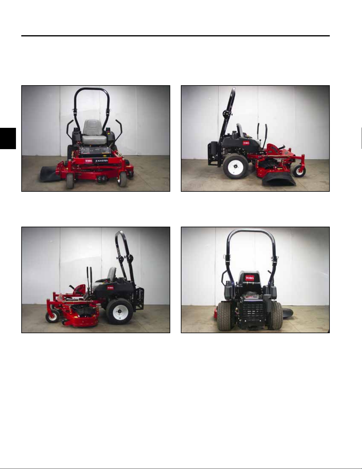
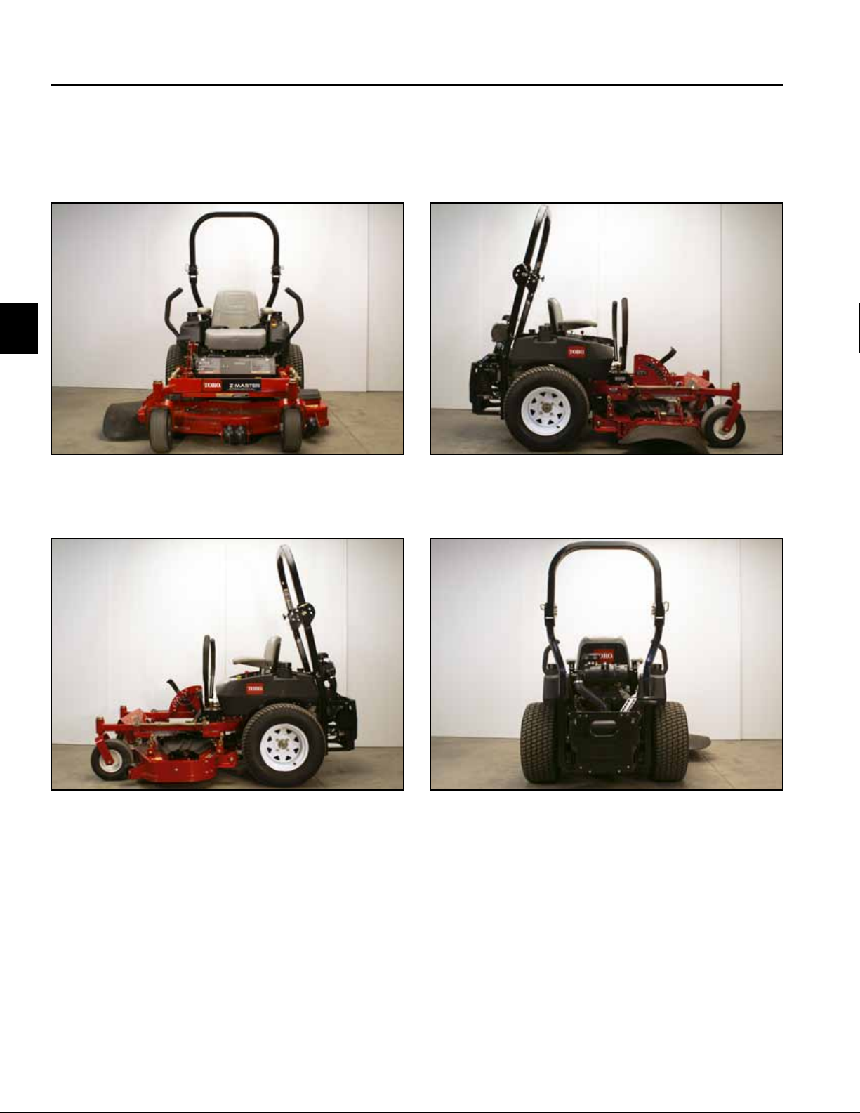
Z 400 Estate Series
19 hp Kawasaki OHV V-Twin
Fig 001 DSC-4765a
Fig 002 DSC-4766a Fig 004 DSC-4768a
Fig 003 DSC-4767a
2-2 Z Master Z400 Service Manual
Page 12
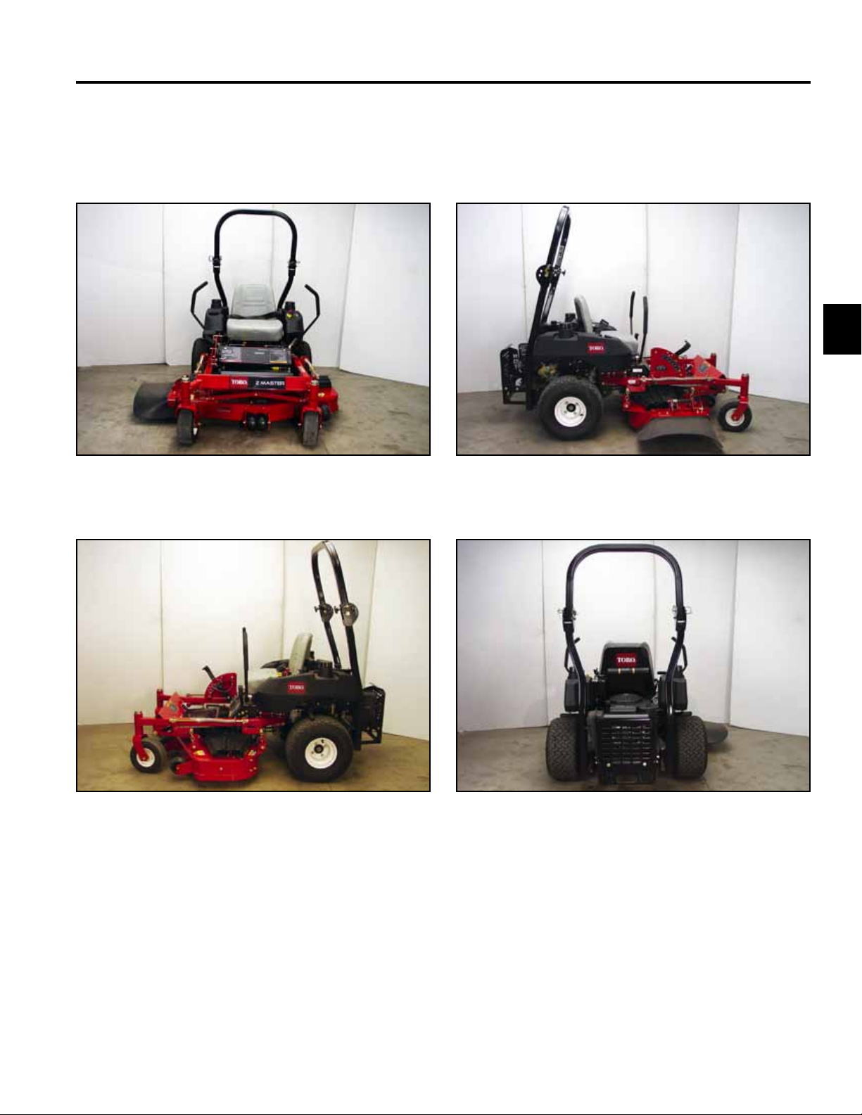
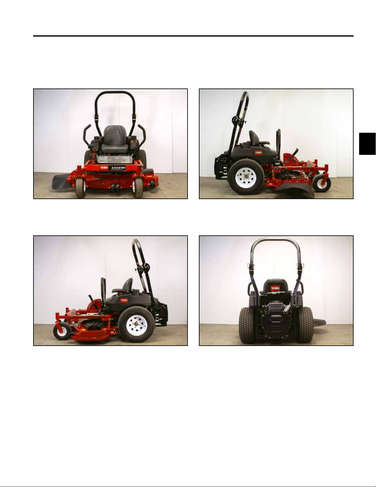
Z 400 Estate Series
18 hp Kohler
SPECIFICATIONS
2
Fig 005 DSC-4842a
Fig 006 DSC-4843a Fig 008 DSC-4846a
Fig 007 DSC-4844a
2-3Z Master Z400 Service Manual
Page 13
2
SPECIFICATIONS
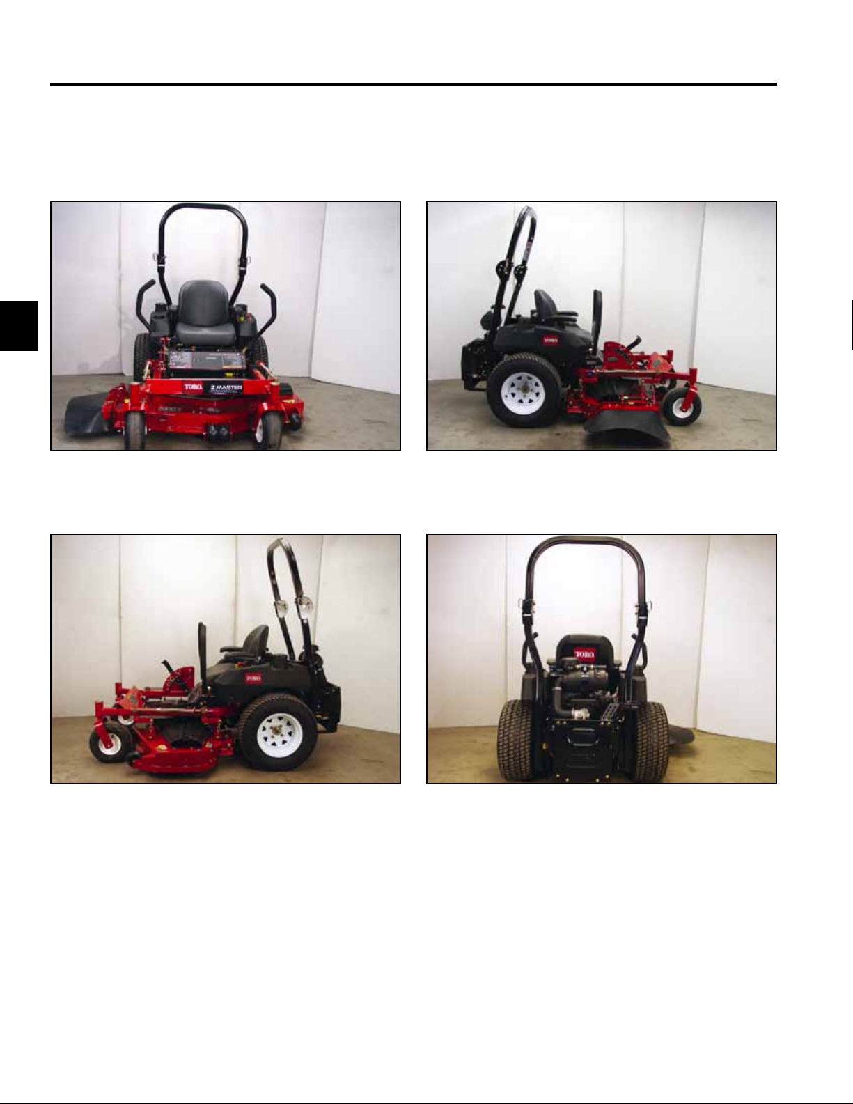
Z 450 Pro Performance Series
20 hp Kohler OHV V-Twin
Fig 009 DSC-4833a
Fig 010 DSC-4834a Fig 012 DSC-4838a
Fig 011 DSC-4835a
2-4 Z Master Z400 Service Manual
Page 14
SPECIFICATIONS
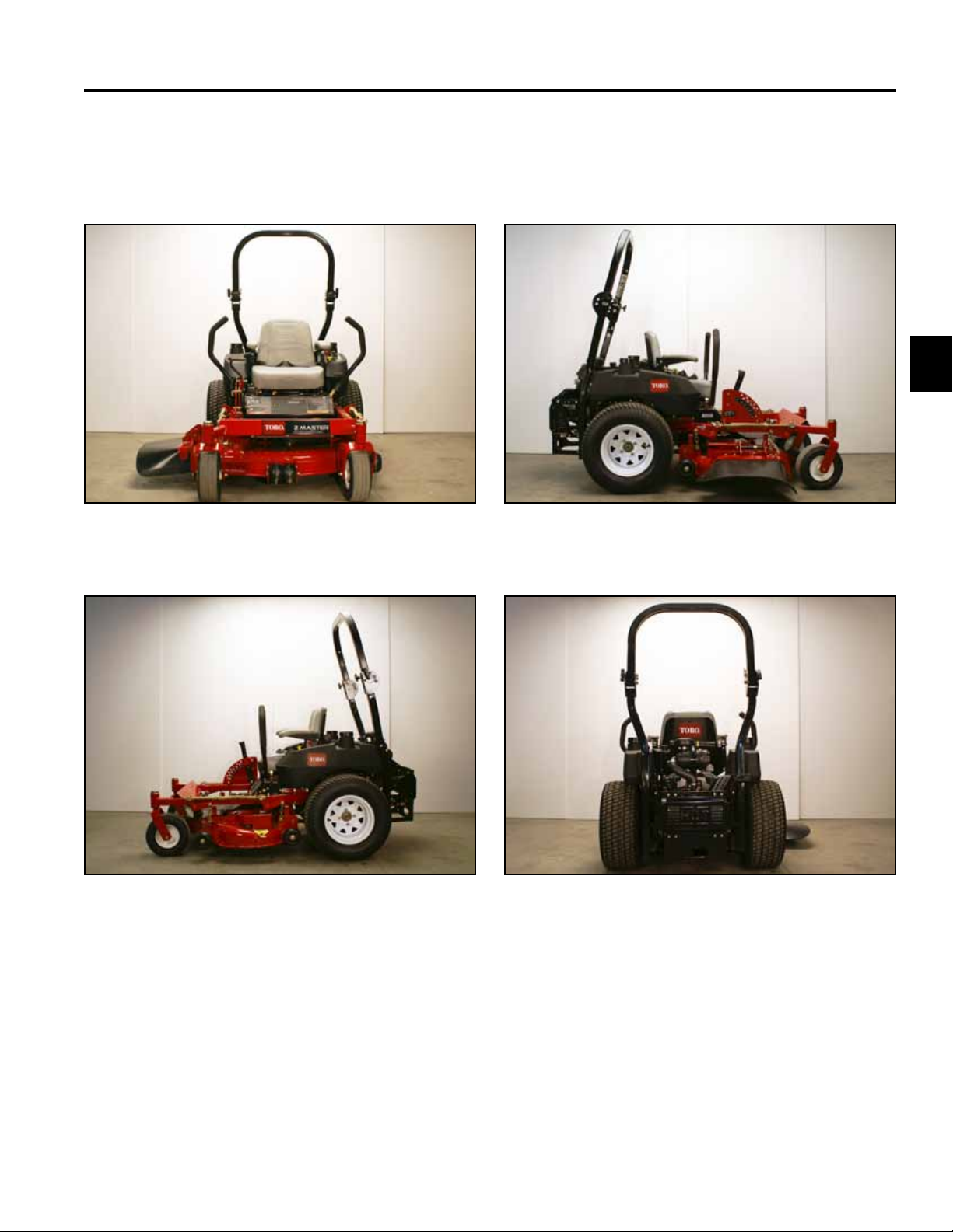
Z 100 Series
19 hp Kawasaki KAI OHV V-Twin
Fig 013 DSC-0437a Fig 015 DSC-0440a
2
Fig 014 DSC-0436a
Fig 016 DSC-0435a
2-5Z Master Z400 Service Manual
Page 15
2
SPECIFICATIONS
Z 450 Pro Performance Series
23 hp Kawasaki OHV V-Twin
Fig 017 DSC-0444a
Fig 018 DSC-0445a Fig 020 DSC-0448a
Fig 019 DSC-0442a
2-6 Z Master Z400 Service Manual
Page 16
Z 440 Pro Value Series
19 hp Kawasaki KAI OHV V-Twin
SPECIFICATIONS
2
Fig 021 DSC-0452a
Fig 022 DSC-0451a Fig 024 DSC-0450a
Fig 023 DSC-0455a
2-7Z Master Z400 Service Manual
Page 17

SPECIFICATIONS
Engines
Output Make High Idle Low Idle Charging Coil
2
19 HP (14.2kW) Kawasaki
OHV V-Twin Forced Air Cooled
18 HP (13.4kW) Kohler
OHV Single Forced Air Cooled
19 HP (14.2kW) Kawasaki
OHV V-Twin Forced Air Cooled
20 HP (14.9kW) Kohler
OHV V-Twin Forced Air Cooled
23 HP (17.1kW) Kawasaki
OHV V-Twin Forced Air Cooled
19 HP (14.2kW) Kawasaki
OHV V-Twin Forced Air Cooled
3650 + 100 RPM 1500 RPM 13 AMP
3650 + 100 RPM 1500 RPM 13 AMP
3650 + 100 RPM 1500 RPM 13 AMP
3650 + 100 RPM 1500 RPM 13 AMP
3650 + 100 RPM 1500 RPM 13 AMP
3650 + 100 RPM 1500 RPM 13 AMP
Dimensions and Weight
ROPS Height Width
Model Weight Folded Upright Deck Deector Length
19 HP Kawasaki
52” 7-Gauge Deck
18 HP Kohler
48” 7-Gauge Deck
924 lbs
(419.2kg)
889 lbs
(407.78kg)
51”
(129.54cm)
51”
(129.54cm)
69”
(175.26cm)
69”
175.26cm)
53.7”
(136.4cm)
49.7”
(126.24cm)
68”
(172.72cm)
64”
(162.56cm)
78”
(198cm)
78”
(198cm)
19 HP Kawasaki
44” SFS Deck
19 HP Kawasaki
48” TF Deck
20 HP Kohler
52” TF Deck
19 HP Kawasaki
52” TF Deck
23 HP Kawasaki
52” TF Deck
23 HP Kawasaki
48” TF Deck
19 HP Kawasaki
44” SFS Deck (112cm)
23 HP Kawasaki
52” TF Deck (132cm)
2-8 Z Master Z400 Service Manual
941 lbs
(426.83kg)
1010 lbs
(458.13kg)
1092 lbs
(495-32kg)
1092 lbs
(495-32kg)
1092 lbs
(495-32kg)
1067 lbs
(483-98kg)
941 lbs
(426.83kg)
1092 lbs
(495.32kg)
52”
(132.08cm)
52”
(132.08cm)
52”
(132.08cm)
52”
(132.08cm)
52”
(132.08cm)
52”
(132.08cm)
52”
(132.08cm)
52”
(132.08cm)
70”
(177.8cm)
70”
(177.8cm)
70”
(177.8cm)
70”
(177.8cm)
70”
(177.8cm)
70”
(177.8cm)
70”
(177.8cm)
70”
(177.8cm)
47”
(119.38cm)
49.7”
(126.24cm)
53.7”
(136.4cm)
53.7”
(136.4cm)
53.7”
(136.4cm)
49.7”
(126.24cm)
47”
(119.38cm)
53.7”
(136.4cm)
61.3”
(155.7cm)
64”
(162.56cm)
68”
(172.72cm)
68”
(172.72cm)
68”
(172.72cm)
64”
(162.56cm)
61.3”
(155.7cm)
68”
(172.72cm)
78”
(198cm)
78”
(198cm)
78”
(198cm)
78”
(198cm)
78”
(198cm)
78”
(198cm)
78”
(198cm)
78”
(198cm)
Page 18

SPECIFICATIONS
Z 400 Series Manual Specications
Frame Assembly Consists of front and rear frames bolted together
Front Frame Welded 2 x 2 x .188” structural steel tube, 7 Gauge front cross member
Rear Frame Welded tube and fabricated steel
Fuel System
Tanks Dual fuel tanks containing large ll necks and vented caps. Rotational
molded high density polyethylene. Mounted above drive wheels.
Capacity 10 gallons (37.8 l) [5 gallons per tank]
Check Valve In-line check valves
Fuel Filter 15 micron, replaceable in-line lter
Traction System
Models with 7-Gauge Deck Models with SFS and TF Decks
Hydraulic Pumps HydroGear 10cc BDP-10A with
2300psi shock valve
Pump Drive
Wheel Motors Parker TE Series (13.9cc) HydroGear HGM-15E (15.4cc)
Ground Speeds Innitely variable:
Forward: 0-7.2 mph (11.6 km/hr)
Reverse: 0-4.2 mph (6.7 km/hr)
Release Valves
Hydraulic Fluid
System Capacity
Contained in Pumps. Allow unit to be moved without engine running.
Mobil 1 Extended Performance 15W-50 Synthetic
Self-tensioning belt drive
2.1 quarts (2.0 liters)
HydroGear 10cc BDP-10A with no shock valve
Innitely variable:
Forward: 0-8.3 mph (13.3 km/hr)
Reverse: 0-5.5 mph (8.8 km/hr)
2
2-9Z Master Z400 Service Manual
Page 19

SPECIFICATIONS
Deck Drive
Models with 7-Gauge Deck Models with SFS and TF Decks
Clutch Warner Electromagnetic “Mag-Stop” with
120 ft-lbs. (162.7 Nm) rating
Type
Take-Up
Deep B-Groove pulley with belt from engine to deck
Spring Idler system
Warner Electromagnetic “Mag-Stop” with
175 ft-lbs. (237-3 Nm) rating
2
Tires
Models with 7-Gauge Deck Models with SFS and TF Decks
Rear Drive Tires 4-ply with “turf master” tread
20” x 10” – 10”
Front Caster Tires 4-ply with smooth tread
11” x 4” – 5”
Tire Pressure
20# rear and 25# front if equipped with mechanical bagger
13psi (90 KPA)
Electrical System
Voltage 12 volt, negative ground
Battery Type 230 CCA
Fuses Blade type. Located by LH Side Control
4-ply with “turf master” tread
23” x 9.5” – 12” [Except as noted]
4-ply with smooth tread
13” x 5” – 6” [Except as noted]
2-10 Z Master Z400 Service Manual
Page 20

SPECIFICATIONS
Cutting Decks
48” (121.9cm)
&
52” (132.1cm)
7-Gauge Deck
Conguration
Construction 7-Gauge,
High Strength
50,000 psi
(3515.3 Kg-f
/ 59cm)
steel welded
construction.
3/8” (9.5mm)
steel
discharge
reinforcement
plate
Discharge Rubber
Blade Tip
Speed
Height of Cut
Rubber discharge chute, spring
biased down toward operating
position
Adjustable from the seat with range of 1.5” (38mm) – 4.5” (114mm) in .25” (6.4mm) increments.
44” (111.8cm)
SFS Deck
Side Discharge, mid-mounted rotary with three blades.
Drawn 12
gauge steel
super ow
system deck
with welded
mounting
brackets and
gage wheel
brackets. 1/2”
(12.7mm)
diameter steel
reinforcement
rod on left
side. 11 gauge
steel front
reinforcement
plate doubles
as bagger
attachment
point
48” (121.9cm)
TF Deck
7 Gauge, High Strength
50,000 psi (3515.3 Kg-f /
59cm) steel 5” (12.7cm)
advanced Turbo Force ow
system, welded construction.
3/8” (9.5mm) steel discharge
reinforcement plate doubles
as a bagger attachment point.
Rubber discharge chute, spring
biased down toward operating
position. Adjustable ow
control bafe.
18,000+ ft/min (548.640cm/min) at high idle
52” (132.1cm)
TF Deck
112cm (44”)
SFS Deck
Drawn 12
gauge steel
super ow
system deck
with welded
mounting
brackets and
gage wheel
brackets. 1/2”
(12.7mm)
diameter steel
reinforcement
rod on left
side. 11 gauge
steel front
reinforcement
plate doubles
as bagger
attachment
point.
discharge
chute, spring
biased down
toward
operating
position
132cm (52”)
TF Deck
7 Gauge,
High Strength
50,000 psi
(3515.3 Kg-f
/ 59cm) steel
5” (12.7cm)
advanced
Turbo Force
ow system,
welded
construction.
3/8” (9.5mm)
steel
discharge
reinforcement
plate doubles
as a bagger
attachment
point.
Rubber
discharge
chute, spring
biased down
toward
operating
position.
Adjustable
ow control
bafe.
2
2-11Z Master Z400 Service Manual
Page 21

SPECIFICATIONS
Cutting Decks cont.
2
48” (121.9cm)
&
52” (132.1cm)
7-Gauge Deck
Deck
Suspension
Belt Covers Plastic HDPE
Gage Wheels Three
Deck
suspended
from machine
by four lift
chains, and
attached to
front cross
member by at
strut arms and
cross brace.
The deck is
pulled along
the ground.
deck covers.
Attached with
swell latches.
adjustable
gage wheels
to reduce
scalping on
the front of
deck (one on
the left-hand
side and two
in the center).
Wheels
have four
adjustment
positions.
44” (111.8cm)
SFS Deck
Deck suspended from machine by four lift chains, and attached to rear
wheel supports by two struts. The deck is pulled along the ground.
14-gauge,
formed steel
covers with
access holes
to allow
greasing of
outer spindles
without
removal.
Attached with
draw latches.
Three adjustable gage wheels to reduce scalping: three on front of deck (one
on left-hand side and two in center). Wheels have four adjustment positions.
Rear gage wheels are optional.
48” (121.9cm)
TF Deck
Plastic HDPE deck covers.
Attached with swell latches.
52” (132.1cm)
TF Deck
112cm (44”)
SFS Deck
14-gauge,
formed steel
covers with
access holes
to allow
greasing of
outer spindles
without
removal.
Attached with
draw latches.
132cm (52”)
TF Deck
Plastic HDPE
deck covers.
Attached with
swell latches.
2-12 Z Master Z400 Service Manual
Page 22
SPECIFICATIONS
4 3 2 1
D
C
B
NOTES:
12. MUST NOT SHOW LOSS OF ADHESION OR LEGIBILITY
AFTER 15 MINUTES IMMERSION IN GASOLINE.
11. MUST BE PROVIDED BY A SILKSCREEN VENDOR.
10. MUST BE PROVIDED IN ROLL DISPENSE, SHEET FORM
OR SPLIT BACKING.
9. MUST HAVE TEDLAR CLEAR OVER LAMINATE FOR ABRASION,
GASOLINE RESISTANCE.
8. MUST COMPLY WITH (TURF) ANSI B71.4-1999 WHEN
APPLIED TO PAINTED METAL OR POLYETHYLENE
FOR A PERIOD OF 24 HOURS.
7. ORIGINAL ARTWORK SHALL BE PROVIDED BY TORO
ENGINEERING DEPARTMENT, BLOOMINGTON, MN.
6. DECAL SHALL LOSE NONE OF ITS INITIAL PROPERTIES
OR DIMENSIONS WHEN STORED BY TORO FOR ONE
YEAR AT TEMPERATURES BELOW 100
o
F AND OUT OF
DIRECT SUNLIGHT. DURING STORAGE, ADHESIVE
SHALL NOT MIGRATE OR LOSE EFFECTIVENESS.
5. ARTWORK MUST BE CENTERED ON DECAL WITHIN
±.030 UNLESS OTHERWISE SPECIFIED.
4. LETTERING COLOR: TORO CORDLESS BLUE NO. 500-97.
3. LETTERING AND GRAPHICS COLOR: TORO WHITE NO. 500-26.
2. BACKGROUND COLOR: TORO SEMI-GLOSS BLACK NO. 500-41.
1. MATERIAL: AVERY MX3200 WITH 1 MIL. TEDLAR CLEAR OVER
4 3 2 1
D
C
B
NOTES:
12. MUST NOT SHOW LOSS OF ADHESION OR LEGIBILITY
AFTER 15 MINUTES IMMERSION IN GASOLINE.
11. MUST BE PROVIDED BY A SILKSCREEN VENDOR.
10. MUST BE PROVIDED IN ROLL DISPENSE, SHEET FORM
OR SPLIT BACKING.
9. MUST HAVE TEDLAR CLEAR OVER LAMINATE FOR ABRASION,
GASOLINE RESISTANCE.
8. MUST COMPLY WITH (TURF) ANSI B71.4-1999 WHEN
APPLIED TO PAINTED METAL OR POLYETHYLENE
FOR A PERIOD OF 24 HOURS.
7. ORIGINAL ARTWORK SHALL BE PROVIDED BY TORO
ENGINEERING DEPARTMENT, BLOOMINGTON, MN.
6. DECAL SHALL LOSE NONE OF ITS INITIAL PROPERTIES
OR DIMENSIONS WHEN STORED BY TORO FOR ONE
YEAR AT TEMPERATURES BELOW 100
o
F AND OUT OF
DIRECT SUNLIGHT. DURING STORAGE, ADHESIVE
SHALL NOT MIGRATE OR LOSE EFFECTIVENESS.
5. ARTWORK MUST BE CENTERED ON DECAL WITHIN
±.030 UNLESS OTHERWISE SPECIFIED.
4. LETTERING COLOR: TORO CORDLESS BLUE NO. 500-97.
3. LETTERING AND GRAPHICS COLOR: TORO WHITE NO. 500-26.
2. BACKGROUND COLOR: TORO SEMI-GLOSS BLACK NO. 500-41.
Lubrication Fittings
48”/52” (132.1cm/121.9cm)
SFS and TF Decks
7-Gauge Decks
Front Caster Pivots 2 removable plugs (1 per side) for periodic lubrication
Front Caster Wheels n/a 2 ttings (1 per side)
Lift Assembly 5 ttings
Brake Arms 2 ttings (1 per side)
Rear Deck Struts 2 ttings (1 per side)
Deck Spindles 3 ttings (1 per spindle)
Pump Idler Pivot 1 tting
General Specications
Greasing and Lubrication:
Grease: No. 2 general purpose lithium base or molybdenum grease
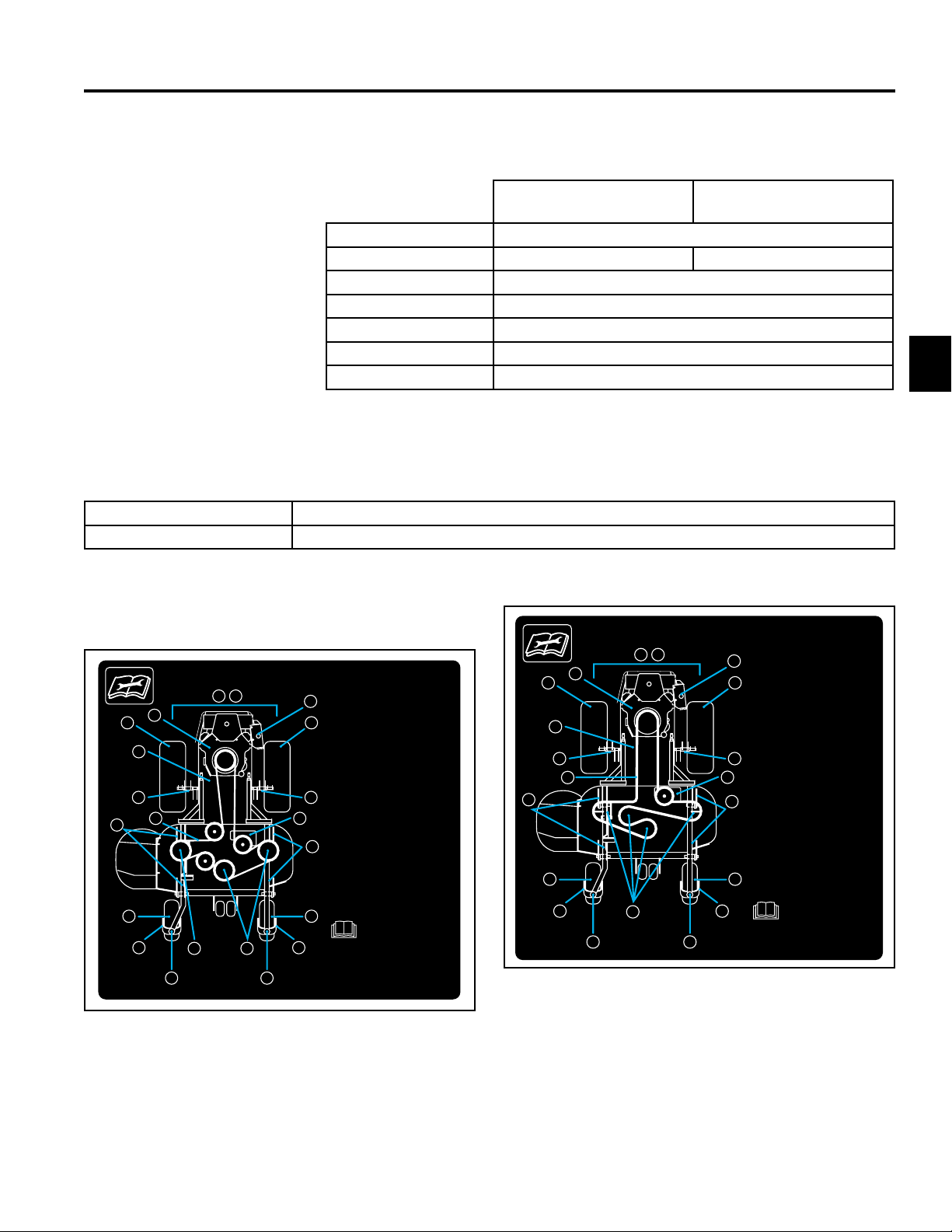
Where to add grease: See Service Aid and Belt Routing decals below (Fig. 025, 026, 027, 028).
Service Aid Decals
SERVICE AID AND BELT ROUTING
11 12
SERVICE AID AND BELT ROUTING
11 12
1
3
10
9
6
3
5
4
13
4
Fig 025 108-4050
19 hp Kawasaki / 44” SFS Deck
2
Every 10 hours (daily):
3
1. Check engine oil
Every 50 hours:
2. Check hydraulic oil
3. Check tire pressure--13 psi
4. Grease blade spindle bearings
5. Grease front wheel bearings
6. Grease deck lift linkage
9
7. Grease belt idler
Every 250 hours:
78
8. Inspect belt and tension
9. Grease brake linkage
10. Grease belt idler
6
Every 1000 hours (yearly):
11. Inspect covers and
safety systems
12. Inspect fasteners and hoses
13. Grease front caster pivot
3
5
See operator's manual for
additional details.
13
108-4050
Fig 026 107-1687A
19 hp Kawasaki / 52” 7-Gauge Deck
18 hp Kohler / 48” 7-Gauge Deck
19 hp Kawasaki / 48” TF Deck
20 hp Kohler / 52” TF Deck
19 hp Kawasaki / 52” TF Deck
23 hp Kawasaki / 52” TF Deck
23 hp Kawasaki / 48” TF Deck
1
3
10
8
9
6
3
5
4
13
13
2
Every 10 hours (daily):
3
1. Check engine oil
Every 50 hours:
2. Check hydraulic oil
3. Check tire pressure--13 psi
4. Grease blade spindle bearings
5. Grease front wheel bearings
6. Grease deck lift linkage
8
7. Grease belt idler
7
Every 250 hours:
8. Grease brake linkage
6
9. Inspect belt and tension
10. Grease belt idler
Every 1000 hours (yearly):
11. Inspect covers and
safety systems
12. Inspect fasteners and hoses
3
13. Grease front caster pivot
5
See operator's manual for
additional details.
107-1687
2
2-13Z Master Z400 Service Manual
Page 23
SPECIFICATIONS
4 3 2 1
D
C
B
NOTES:
12. MUST NOT SHOW LOSS OF ADHESION OR LEGIBILITY
AFTER 15 MINUTES IMMERSION IN GASOLINE.
11. MUST BE PROVIDED BY A SILKSCREEN VENDOR.
10. MUST BE PROVIDED IN ROLL DISPENSE, SHEET FORM
OR SPLIT BACKING.
9. MUST HAVE TEDLAR CLEAR OVER LAMINATE FOR ABRASION,
GASOLINE RESISTANCE.
8. MUST COMPLY WITH (TURF) ANSI B71.4-1999 WHEN
APPLIED TO PAINTED METAL OR POLYETHYLENE
FOR A PERIOD OF 24 HOURS.
7. ORIGINAL ARTWORK SHALL BE PROVIDED BY TORO
ENGINEERING DEPARTMENT, BLOOMINGTON, MN.
6. DECAL SHALL LOSE NONE OF ITS INITIAL PROPERTIES
OR DIMENSIONS WHEN STORED BY TORO FOR ONE
YEAR AT TEMPERATURES BELOW 100
o
F AND OUT OF
DIRECT SUNLIGHT. DURING STORAGE, ADHESIVE
SHALL NOT MIGRATE OR LOSE EFFECTIVENESS.
5. ARTWORK MUST BE CENTERED ON DECAL WITHIN
±.030 UNLESS OTHERWISE SPECIFIED.
4. LETTERING COLOR: TORO CORDLESS BLUE NO. 500-97.
3. LETTERING AND GRAPHICS COLOR: TORO WHITE NO. 500-26.
2. BACKGROUND COLOR: TORO SEMI-GLOSS BLACK NO. 500-41.
1. MATERIAL: AVERY MX3200 WITH 1 MIL. TEDLAR CLEAR OVER
LAMINATE.
PRODUCT: Z 100 SERIES CE
4 3 2 1
D
C
B
NOTES:
12. MUST NOT SHOW LOSS OF ADHESION OR LEGIBILITY
AFTER 15 MINUTES IMMERSION IN GASOLINE.
11. MUST BE PROVIDED BY A SILKSCREEN VENDOR.
10. MUST BE PROVIDED IN ROLL DISPENSE, SHEET FORM
OR SPLIT BACKING.
9. MUST HAVE TEDLAR CLEAR OVER LAMINATE FOR ABRASION,
GASOLINE RESISTANCE.
8. MUST COMPLY WITH (TURF) ANSI B71.4-1999 WHEN
APPLIED TO PAINTED METAL OR POLYETHYLENE
FOR A PERIOD OF 24 HOURS.
7. ORIGINAL ARTWORK SHALL BE PROVIDED BY TORO
ENGINEERING DEPARTMENT, BLOOMINGTON, MN.
6. DECAL SHALL LOSE NONE OF ITS INITIAL PROPERTIES
OR DIMENSIONS WHEN STORED BY TORO FOR ONE
YEAR AT TEMPERATURES BELOW 100
o
F AND OUT OF
DIRECT SUNLIGHT. DURING STORAGE, ADHESIVE
SHALL NOT MIGRATE OR LOSE EFFECTIVENESS.
5. ARTWORK MUST BE CENTERED ON DECAL WITHIN
±.030 UNLESS OTHERWISE SPECIFIED.
4. LETTERING COLOR: TORO CORDLESS BLUE NO. 500-97.
3. LETTERING AND GRAPHICS COLOR: TORO WHITE NO. 500-26.
2. BACKGROUND COLOR: TORO SEMI-GLOSS BLACK NO. 500-41.
2
11 12
1
3
10
8
9
6
3
5
4
13
2
10
1.
3
50
2.
3.
4.
5.
8
6.
7
5
13
7.
250
6
8.
9.
10.
1000
11.
3
12.
13.
107-1686
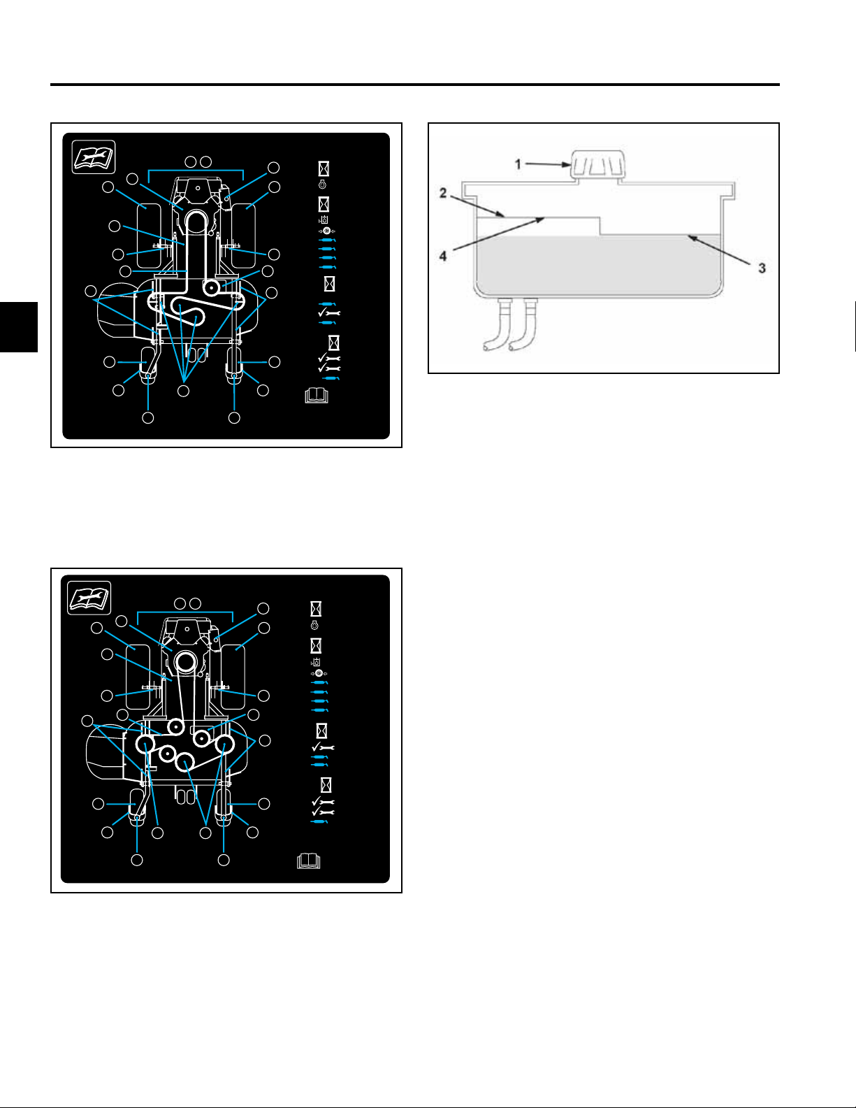
Fig 027 107-1686A
23 hp Kawasaki / 132cm (52” TF Deck)
Fig 029 g. 55 m-5615
1. Cap 3. Cold uid level - full
2. Bafe 4. Hot uid level - full
11 12
1
3
10
9
6
3
5
4
13
4
Fig 028 108-4051
19 hp Kawasaki / 112cm (44” SFS Deck)
2-14 Z Master Z400 Service Manual
2
10
1.
3
50
2.
3.
4.
9
78
5
13
5.
6.
7.
250
6
8.
9.
10.
1000
11.
3
12.
13.
108-4051
Page 24
SPECIFICATIONS
Hydraulic System Oil Capacity: 2.1 quarts (2.0 liters)
Fluid Type: Mobil 1 Extended Performance 15W-50 Synthetic
Fluid Level: Check the uid level while the uid is warm. The uid should be between cold
and hot.
Note: The uid level should be to the top of the hot level of the bafe,
when the uid is hot (Fig. 000 above).
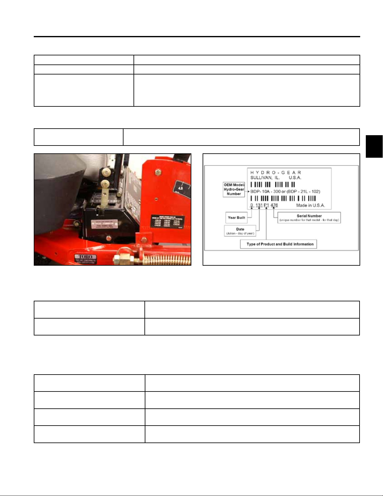
Model and Serial Number
Location
The unit model and serial number plate is located on the right hand side of the unit,
below the right side motion control lever (Fig. 000).
Fig 030 PICT-0046
Engine Model and Serial Number
Identication:
Hydrostatic Pumps Model and Serial
Number:
Consult the appropriate engine manufacture’s service literature for the
location and translation of the engine model and serial number information.
The label (Fig. 000), can be located on the pump housing. It identies the
model and conguration of the BDP pump.
2
Fig 031 conguration
Available Service Manuals / Service Aids
Hydrostatic Pumps: Hydro-Gear BDP-10A/16A/21L – Service and Repair Manual
Form # 492-4789
Wheel Motors: Parker/Ross Wheel Motor Service Manual
Form # 492-4753
Hydraulic Troubleshooting: Interactive hydraulic troubleshooting and failure analysis on compact disk
Form #492-4777
Electrical Troubleshooting: Interactive electrical troubleshooting and wiring diagrams on compact disk
Form #492-9143
2-15Z Master Z400 Service Manual
Page 25
SPECIFICATIONS
2
Torque Specifications
Recommended fastener torque values are listed in the
following tables. For critical applications, as
determined by Toro, either the recommended torque or
a torque that is unique to the application is clearly
identified and specified in the service manual.
These torque specifications for the installation and
tightening of fasteners shall apply to all fasteners which
do not have a specific requirement identified in the
service manual. The following factors shall be
considered when applying torque: cleanliness of the
fastener, use of a thread sealant (Loctite), degree of
lubrication on the fastener, presence of a prevailing
torque feature, hardness of the surface underneath of
the fastener’s head, or similar condition which affects
the installation.
As noted in the following tables, torque values should
be reduced by 25% for lubricated fasteners to
achieve the similar stress as a dry fastener. Torque
values may also have to be reduced when the fastener
is threaded into aluminum or brass. The specific
torque value should be determined based on the
aluminum or brass material strength, fastener size,
length of thread engagement, etc.
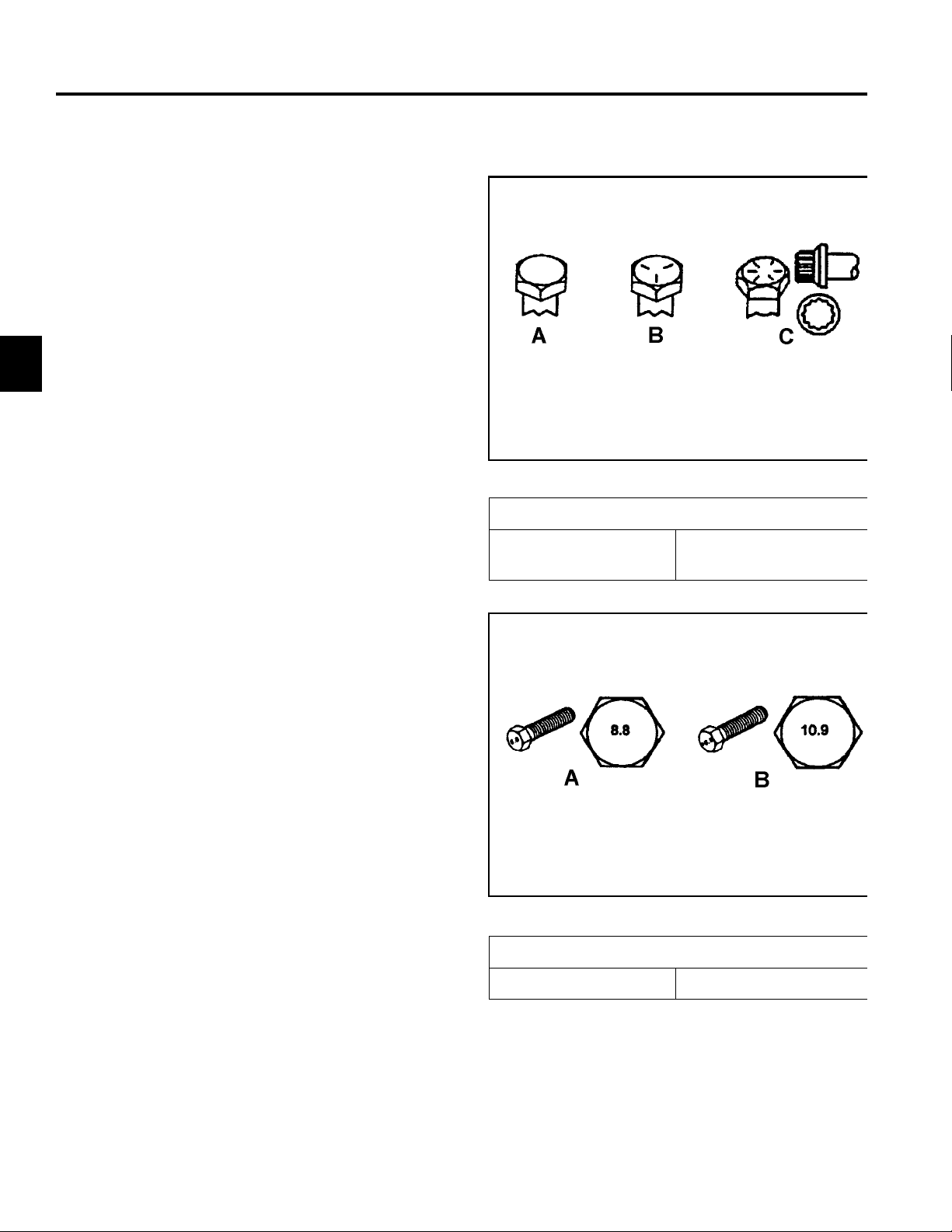
Fastener Identification
Inch Series Bolts and Screws
(A) Grade 1
(B) Grade 5
Figure A
(C) Grade 8
The standard method of verifying torque shall be
performed by marking a line on the fastener (head or
nut) and mating part, then back off fastener 1/4 of a
turn. Measure the torque required to tighten the
fastener until the lines match up.
Figure B
Metric Bolts and Screws
(A) Class 8.8 (B) Class 10.9
2-16 Z Master Z400 Service Manual
Page 26

SPECIFICATIONS
SAE Grade 8 Bolts, Screws,
Studs, & Sems with Regular
2
Standard Torque for Dry, Zinc Plated, and Steel Fasteners (Inch Series)
Grade 1, 5, &
Thread Size
# 6 - 32 UNC
# 6 - 40 UNF 17 ± 2 190 ± 20 25 ± 2 280 ± 20
# 8 - 32 UNC
# 8 - 36 UNF 31 ± 3 350 ± 30 43 ± 4 31 ± 3
# 10 - 24 UNC
#10 - 32 UNF 48 ± 4 540 ± 45 68 ± 6 765 ± 70
1/4 - 20 UNC 48 ± 7 53 ± 7 599 ± 79 100 ± 10 1125 ± 100 140 ± 15 1580 ± 170
1/4 - 28 UNF 53 ± 7 65 ± 10 734 ± 113 115 ± 10 1300 ± 100 160 ± 15 1800 ± 170
5/16 - 18 UNC 115 ± 15 105 ± 17 1186 ± 169 200 ± 25 2250 ± 280 300 ± 30 3390 ± 340
5/16 - 24 UNF 138 ± 17 128 ± 17 1446 ± 192 225 ± 25 2540 ± 280 325 ± 30 3670 ± 340
3/8 - 16 UNC 16 ± 2 16 ± 2 22 ± 3 30 ± 3 41 ± 4 43 ± 4 58 ± 5
3/8 - 24 UNF 17 ± 2 18 ± 2 24 ± 3 35 ± 3 47 ± 4 50 ± 4 68 ± 5
7/16 - 14 UNC 27 ± 3 27 ± 3 37 ± 4 50 ± 5 68 ± 7 70 ± 7 68 ± 9
7/16 - 20 UNF 29 ± 3 29 ± 3 39 ± 4 55 ± 5 75 ± 7 77 ± 7 104 ± 9
1/2 - 13 UNC 30 ± 3 48 ± 7 65 ± 9 75 ± 8 102 ± 11 105 ± 10 142 ± 14
1/2 - 20 UNF 32 ± 3 53 ± 7 72 ± 9 85 ± 8 115 ± 11 120 ± 10 163 ± 14
5/8 - 11 UNC 65 ± 10 88 ± 12 119 ± 16 150 ± 15 203 ± 20 210 ± 20 285 ± 27
5/8 - 18 UNF 75 ± 10 95 ± 15 129 ± 20 170 ± 15 230 ± 20 240 ± 20 325 ± 27
3/4 - 10 UNC 93 ± 12 140 ± 20 190 ± 27 265 ± 25 359 ± 34 374 ± 35 508 ± 47
3/4 - 16 UNF 115 ± 15 165 ± 25 224 ± 34 300 ± 25 407 ± 34 420 ± 35 569 ± 47
7/8 - 9 UNC 140 ± 20 225 ± 25 305 ± 34 430 ± 45 583 ± 61 600 ± 60 813 ± 81
7/8 - 14 UNF 155 ± 25 260 ± 30 353 ± 41 475 ± 45 644 ± 61 660 ± 60 895 ± 81
8 with Thin
Height Nuts
In-lb In-lb N-cm In-lb N-cm In-lb N-cm
10 ± 2 13 ± 2 147 ± 23
13 ± 2 25 ± 5 282 ± 30
18 ± 2 30 ± 5 339 ± 56
ft-lb ft-lb N-m ft-lb N-m ft-lb N-m
SAE Grade 1 Bolts, Screws,
Studs, & Sems with Regular
Height Nuts (SAE J995
Grade 2 or Stronger Nuts)
SAE Grade 5 Bolts, Screws,
Studs, & Sems with Regular
Height Nuts (SAE J995
Grade 2 or Stronger Nuts)
15 ± 2 170 ± 20 23 ± 2 260 ± 20
29 ± 3 330 ± 30 41 ± 4 460 ± 45
42 ± 4 475 ± 45 60 ± 6 674 ± 70
Height Nuts (SAE J995
Grade 2 or Stronger Nuts)
2
Note: Reduce torque values listed in the table above
by 25% for lubricated fasteners. Lubricated fasteners
are defined as threads coated with a lubricant such as
oil, graphite, or thread sealant such as Loctite.
Note: Torque values may have to be reduced when
installing fasteners into threaded aluminum or brass.
The specific torque value should be determined based
on the fastener size, the aluminum or base material
strength, length of thread engagement, etc.
Note: The nominal torque values listed above for
Grade 5 and 8 fasteners are based on 75% of the
minimum proof load specified in SAE J429. The
tolerance is approximately
value. Thin height nuts include jam nuts.
± 10% of the nominal torque
2-17Z Master Z400 Service Manual
Page 27

SPECIFICATIONS
Standard Torque for Dry, Zinc, and Steel Fasteners (Metric Fasteners)
2
Class 8.8 Bolts, Screws, and Studs with
Thread Size
M5 X 0.8 57 ± 5 in-lb 640 ± 60 N-cm 78 ± 7 in-lb 885 ± 80 N-cm
M6 X 1.0 96 ± 9 in-lb 1018 ± 100 N-cm 133 ± 13 in-lb 1500 ± 150 N-cm
M8 X 1.25 19 ± 2 ft-lb 26 ± 3 N-m 27 ± 2 ft-lb 36 ± 3 N-m
M10 X 1.5 38 ± 4 ft-lb 52 ± 5 N-m 53 ± 5 ft-lb 72 ± 7 N-m
M12 X 1.75 66 ± 7 ft-lb 90 ± 10 N-m 92 ± 9 ft-lb 125 ± 12 N-m
M16 X 2.0 166 ± 15 ft-lb 225 ± 20 N-m 229 ± 22 ft-lb 310 ± 30 N-m
M20 X 2.5 325 ± 33 ft-lb 440 ± 45 N-m 450 ± 37 ft-lb 610 ± 50 N-m
Note: Reduce torque values listed in the table above
by 25% for lubricated fasteners. Lubricated fasteners
are defined as threads coated with a lubricant such as
oil, graphite, or thread sealant such as Loctite.
Note: Torque values may have to be reduced when
installing fasteners into threaded aluminum or brass.
The specific torque value should be determined based
on the fastener size, the aluminum or base material
strength, length of thread engagement, etc.
Regular Height Nuts
(Class 8 or Strong Nuts)
Note: The nominal torque values listed above are
based on 75% of the minimum proof load specified in
SAE J1199. The tolerance is approximately
the nominal torque value. Thin height nuts include jam nuts.
Class 10.9 Bolts, Screws, and Studs with
Regular Height Nuts (
Class 10 or Strong Nuts)
± 10% of
2-18 Z Master Z400 Service Manual
Page 28

Other Torque Specifications
SPECIFICATIONS
SAE Grade 8 Steel Set Screws
Recommended Torque
Thread Size
Square Head Hex Socket
1/4 - 20 UNC 140 ± 20 in-lb 73 ± 12 in-lb
5/16 - 18 UNC 215 ± 35 in-lb 145 ± 20 in-lb
3/8 - 16 UNC 35 ± 10 ft-lb 18 ± 3 ft-lb
1/2 - 13 UNC 75 ± 15 ft-lb 50 ± 10 ft-lb
Thread Cutting Screws
(Zinc Plated Steel)
Type 1, Type 23, or Type F
Thread Size Baseline Torque*
No. 6 - 32 UNC 20 ± 5 in-lb
Wheel Bolts and Lug Nuts
Thread Size Recommended Torque**
7/16 - 20 UNF
Grade 5
1/2 - 20 UNF
Grade 5
M12 X 1.25
Class 8.8
M12 X 1.5
Class 8.8
** For steel wheels and non-lubricated fasteners.
Thread Cutting Screws
Thread
Size
No. 6 18 20 20 ± 5 in-lb
Threads per Inch
Type A Type B
65 ± 10 ft-lb 88 ± 14 N-m
80 ± 10 ft-lb 108 ± 14 N-m
80 ± 10 ft-lb 108 ± 14 N-m
80 ± 10 ft-lb 108 ± 14 N-m
(Zinc Plated Steel)
Baseline Torque*
2
No. 8 - 32 UNC 30 ± 5 in-lb
No.10 - 24 UNC 38 ± 7 in-lb
1/4 - 20 UNC 85 ± 15 in-lb
5/16 - 18 UNC 110 ± 20 in-lb
3/8 - 16 UNC 200 ± 100 in-lb
Conversion Factors
in-lb X 11.2985 - N-cm
ft-lb X 1.3558 = N-m
No. 8 15 18 30 ± 5 in-lb
No. 10 12 16 38 ± 7 in-lb
No. 12 11 14 85 ± 15 in-lb
* Hole size, material strength, material thickness and
finish must be considered when determining specific
torque values. All torque values are based on nonlubricated fasteners.
N-cm X - 0.08851 = in-lb
N-cm X 0.73776 - ft-lb
2-19Z Master Z400 Service Manual
Page 29

2
SPECIFICATIONS
Equivalents and Conversions
Decimal and Millimeter Equivalents
Fractions Decimals mm Fractions Decimals mm
1/64 0.015625 0.397 33/64 0.515625 13.097
1/32 0.03125 0.794 16/32 0.53125 13.484
3/64 0.046875 1.191 35/64 0.546875 13.891
1/16 0.0625 1.588 9/16 0.5625 14.288
5/64 0.078125 1.984 37/64 0.578125 14.684
3/32 0.9375 2.381 19/32 0.59375 15.081
1/8 0.1250 3.175 5/8 0.6250 15.875
9/64 0.140625 3.572 41/64 0.640625 16.272
5/32 0.15625 3.969 21/32 0.65625 16.669
11/64 0.171875 4.366 43/64 0.671875 17.066
3/16 0.1875 4.762 11/16 0.6875 17.462
13/64 0.203125 5.159 45/64 0.703125 17.859
7/32 0.21875 5.556 23/32 0.71875 18.256
15/64 0.234375 5.953 47/64 0.734375 18.653
1/4 0.2500 6.350 3/4 0.7500 19.050
17/64 0.265625 6.747 49/64 0.765625 19.447
9/32 0.28125 7.144 25/32 0.78125 19.844
19/64 0.296875 7.541 51/64 0.796875 20.241
5/16 0.3125 7.541 13/16 0.8125 20.638
21/64 0.328125 8.334 53/64 0.828125 21.034
11/32 0.34375 8.731 27/32 0.84375 21.431
23/64 0.359375 9.128 55/64 0.859375 21.828
3/8 0.3750 9.525 7/8 0.8750 22.225
25/64 0.390625 9.922 57/64 0.890625 22.622
13/32 0.40625 10.319 29/32 0.90625 23.019
27/64 0.421875 10.716 59/64 0.921875 23.416
7/16 0.4375 11.112 15/16 0.9375 23.812
29/64 0.453125 11.509 61/64 0.953125 24.209
15/32 0.46875 11.906 31/32 0.96875 24.606
31/64 0.484375 12.303 63/64 0.984375 25.003
1/2 0.5000 12.700 1 1.000 25.400
1 mm = 0.03937 in. 0.001 in. = 0.0254 mm
2-20 Z Master Z400 Service Manual
Page 30

Linear
Measurement
Area
Volume
Weight
Pressure
Work
Liquid Volume
Liquid Flows
Temperature
SPECIFICATIONS
U.S. to Metric Conversions
To Convert Into Multiply By
Miles
Yards
Feet
Feet
Inches
Inches
Inches
Square Miles
Square Feet
Square Inches
Acre
Cubic Yards
Cubic Feet
Cubic Inches
Tons (Short)
Pounds
Ounces
Pounds/Sq. In. Kilopascal
Foot-pounds
Foot-pounds
Inch-pounds
Quarts
Gallons
Gallons/Minute Liters/Minute
Fahrenheit Celsius
Kilometers
Meters
Meters
Centimeters
Meters
Centimeters
Millimeters
Square Kilometers
Square Meters
Square Centimeters
Hectare
Cubic Meters
Cubic Meters
Cubic Centimeters
Metric Tons
Kilograms
Grams
Newton-Meters
Kilogram-Meters
Kilogram-Centimeters
Liters
Liters
1.609
0.9144
0.3048
30.48
0.0254
2.54
25.4
2.59
0.0929
6.452
0.4047
0.7646
0.02832
16.39
0.9078
0.4536
28.3495
6.895
1.356
0.1383
1.152144
0.9463
3.785
3.785
1. Subtract 32°
2. Multiply by 5/9
2
2-21Z Master Z400 Service Manual
Page 31

2
SPECIFICATIONS
THIS PAGE INTENTIONALLY LEFT BLANK.
2-22 Z Master Z400 Service Manual
Page 32

CHASSIS
Safety Information . . . . . . . . .
Specications . . . . . . . . . . .
Chassis . . . . . . . . . . . . . .
Hydraulic System . . . . . . . . .
Engine . . . . . . . . . . . . . . .
1
2
3
4
5
Electrical . . . . . . . . . . . . . .
Mower Decks . . . . . . . . . . .
3-1Z Master Z400 Service Manual
6
7
Page 33

CHASSIS
3
Caster Fork Assembly Removal
Estate Series with bushing front casters
1. Raise the front of the unit off the ground, allowing
enough clearance to remove the caster fork from the
bottom hub.
2. With a hammer and chisel, remove the top grease
cap (Fig. 032).
4. Remove the caster fork assembly from the front
frame (Fig. 034).
Fig 034 PICT-0003
5. Remove the spacer (Fig. 035).
Fig 032 PICT-0001 rev
3. Remove the E-ring (Fig. 033).
Fig 033 PICT-0002
Fig 035 PICT-0004
3-2 Z Master Z400 Service Manual
Page 34

CHASSIS
6. Remove the top and bottom bushings (Fig. 036).
Fig 036 PICT-0005 rev
Caster Fork Assembly Installation
2. Install the caster fork assembly into the front frame
(Fig. 038).
Fig 038 PICT-0008
Note: Ensure short caster spacer is installed prior
to assembling the caster assembly.
3
Estate Series with bushing front casters
1. Drive the upper and lower bushings in until they seat
against the step in the housing (Fig. 037).
Fig 037 PICT-0006 rev
3. Install the tall spacer (Fig. 039).
Fig 039 PICT-0009
3-3Z Master Z400 Service Manual
Page 35

CHASSIS
3
4. When reinstalling the castor fork assembly on early
production Z400 Estates Series check for excessive
endplay between the E-ring groove and the top of
the spacer. To minimize endplay, adjust as needed
with 7/8” ID shims (Fig. 040).
Fig 040 PICT-0010
6. Install the top grease cap (Fig 042).
Fig 042 PICT-0012
Caster Fork Assembly Removal
5. Install the E-ring (Fig. 041).
Fig 041 PICT-0011 rev
Pro 100/400 Series with tapered roller front casters
1. Raise the front of the unit off the ground, allowing
enough clearance to remove the caster fork from the
bottom hub.
2. With a hammer and chisel, remove the top grease
cap (Fig. 043).
Fig 043 PICT-0205
3-4 Z Master Z400 Service Manual
Page 36

CHASSIS
3. Loosen and remove the caster nut (Fig. 044).
Fig 044 PICT-0206
4. Remove the caster fork and wheel assembly from
the frame (Fig. 045)
5. Remove cup washers (3) (Fig. 046).
Fig 046 PICT-0208
6. Remove the top tapered roller bearing (Fig. 047).
3
Fig 045 PICT-0207
Fig 047 PICT-0209
3-5Z Master Z400 Service Manual
Page 37

CHASSIS
3
7. Remove the lower seal and lower tapered bearing
(Fig. 048).
Fig 048 PICT-0210
8. Remove the lower tapered bearing cup (Fig. 049)
9. Remove the upper tapered bearing cup (Fig. 050)
Fig 050 PICT-0212
Caster Fork Assembly Installation
Pro 100/400 Series with tapered roller front casters
Fig 049 PICT-0211
1. Install the upper and lower tapered bearing cups
with the thick edge facing inside (Fig. 051).
Fig 051 PICT-0213
3-6 Z Master Z400 Service Manual
Page 38

CHASSIS
2. Pack the upper and lower tapered roller bearings
prior to installation (Fig. 052).
Fig 052 PICT-0214
3. Install the lower tapered bearing and lower seal with
the open end of the seal facing up (Fig. 053).
4. Install the upper tapered bearing (Fig. 054).
Fig 054 PICT-0216
5. Install the caster fork into the frame (Fig. 055).
3
Fig 053 PICT-0215
Fig 055 PICT-0207
3-7Z Master Z400 Service Manual
Page 39

CHASSIS
3
6. Install the three spring washers (Fig. 056).
A
B
C
Fig 056 washers line art
A. Dust cap C. Spring washers
B. Locknut
8. Remove the grease plug located on the side of the
hub on the frame for the caster fork. Install a grease
tting, and pump grease into the housing until
grease is passing through the upper bearing (Fig.
058).
Fig 058 PICT-0217
7. Install the locknut and tighten until the spring
washers are at, then back off 1/4 turn to properly
set the preload on the bearings (Fig. 057).
Fig 057 PICT-0206
9. Replace the grease plug.
10. Install the top grease cap.
Front Wheel Removal and Bearing
Replacement (Estate Series)
1. Raise the front of the unit off the ground.
3-8 Z Master Z400 Service Manual
Page 40

CHASSIS
2. Remove the wheel bolt and nut from the fork (Fig.
059).
Fig 059 PICT-0013
3. Remove the wheel from the fork (Fig. 060).
4. Remove the spacer nut from one side of the wheel
(Fig. 061).
3
Fig 061 PICT-0015 rev
5. Remove the caster axle and second spacer nut from
the wheel (Fig. 062).
Fig 060 PICT-0014
Fig 062 PICT-0016 rev
3-9Z Master Z400 Service Manual
Page 41

CHASSIS
3
6. Remove both caster seals from the wheel (Fig. 063).
Fig 063 PICT-0017
Caster Fork Wheel and Tire Assembly (Fig. 064)
7. Fill the center of the wheel cavity with grease and
work the grease into the race (Fig. 065).
Fig 065 PICT-0020 rev
8. Pack the wheel bearing prior to installation (Fig.
066).
H
A B C C B A
D
E E
F G
Fig 064 PICT-0018 rev
A. Seal Guard E. Spacer Nuts
B. Caster Seal F. Axle Bolt
C. Taper Cone Bearing G. Axle Bolt Nut
D. Caster Axle H. Wheel & Tire Assembly
Fig 066 PICT-0019 rev
3-10 Z Master Z400 Service Manual
Page 42

CHASSIS
9. Install the wheel bearing (Fig. 067).
Fig 067 PICT-0022 rev
10. Install the caster seal (Fig. 068).
11. Repeat steps 8-10 for the other side of the wheel.
12. Install one spacer nut onto the caster axle (Fig. 069).
3
Fig 069 PICT-0024 rev
Fig 068 PICT-0021 rev
13. Insert caster axle/nut assembly into the wheel hub
and install the second spacer nut (Fig. 070).
Fig 070 PICT-0025 rev
Note: Spacer nuts should be installed an equal
distance onto each end of the caster axle.
3-11Z Master Z400 Service Manual
Page 43

CHASSIS
3
14. Bearing pre-load is established by the torque of the
spacer nuts on the caster axle. Set spacer nuts at 80
in-lbs. (9.0 Nm) with a torque wrench. Loosen, then
reset at 20 in-lbs. (2.3 Nm) (Fig. 071).
Fig 071 PICT-0026 rev
16. Install wheel and tire assembly into caster fork using
wheel bolt and nut (Fig. 073). Tighten.
Fig 073 PICT-0028
Pro 100/400 Series with tapered roller front casters
15. Install both seal guards onto wheel hub (Fig. 072).
Fig 072 PICT-0027
1. Raise the front of the unit off the ground.
2. Remove the wheel bolt and nut from the fork (Fig.
074).
Fig 074 PICT-0218
3-12 Z Master Z400 Service Manual
Page 44

CHASSIS
3. Remove the wheel from the fork (Fig. 075).
Fig 075 PICT-0220
4. Remove both bearing spacers (Fig. 076).
5. Remove the front caster spacer (Fig. 077).
Fig 077 PICT-0222 rev
6. Remove both bearing seals (Fig. 078).
3
Fig 076 PICT-0221 rev
Fig 078 PICT-0223 rev
3-13Z Master Z400 Service Manual
Page 45

CHASSIS
3
7. Remove both taper cone bearings (Fig. 079).
Fig 079 PICT-0224 rev
Caster Fork Wheel and Tire Assembly (Fig. 080).
10. Pack both tapered wheel bearings. Reassemble per
Fig. 000 (above).
Note: The axle bolt torque sets the pre-load on the
front caster wheel bearings. Tighten the axle
bolt to set the bearings then back off 1/4 turn.
Pump grease into the wheel bearings through the
grease tting located on the rim (Fig. 081).
G
A B C C B A
D
E
Fig 080 PICT-0225 rev
A. Seal Guard E. Axle Bolt
B. Caster Seal F. Axle Bolt Nut
C. Taper Cone Bearing G. Wheel & Tire Assembly
D. Caster Axle
F
Fig 081 PICT-0227
Fuel Tank Removal
Left Side Fuel Tank Removal
1. Disconnect the negative battery cable from the
battery. Drain the fuel tank.
3-14 Z Master Z400 Service Manual
Page 46

CHASSIS
2. Remove the fuel hose clamp from the bottom of the
fuel tank (Fig. 082).
Fig 082 PICT-0029
3. Remove the four screws retaining the control panel
to the fuel tank (Fig. 083).
4. Carefully remove the control panel by lifting the
panel and sliding it toward the middle of the unit.
Note: Do not disconnect any cables or wiring.
5. Remove the two bolts, lock washers and at
washers from the front of the tank (Fig. 084).
3
Fig 084 PICT-0031
Fig 083 PICT-0030
6. Locate and remove the two nuts, springs, and
washers from the studs at the rear of the fuel tank
(Fig. 085).
Note: Rear tire removed for clarity.
Fig 085 PICT-0032
3-15Z Master Z400 Service Manual
Page 47

CHASSIS
3
7. Remove the fuel tank from the frame (Fig. 086).
Fig 086 PICT-0033
Left Side Fuel Tank Installation
Location
There are two fuel check valves. They are located one
beneath each fuel tank approx 6” (15.2cm) down line
from the tank (Fig. 087).
Fig 087 PICT-0001b
Reverse the order of removal.
Right Side Fuel Tank Removal & Installation
Follow the same procedures for the Left Side Fuel Tank
Removal and Installation except skip the instructions for
removing the control panel.
Fuel Check Valve
Purpose
The fuel check valve allows fuel to ow in only one
direction and equalizes fuel ow from both tanks.
Proper Installation
Flat side of the check valve faces fuel tank (Fig. 088).
A B
Fig 088 PICT-0002b rev
A. From the tank B. To the engine
3-16 Z Master Z400 Service Manual
Page 48

CHASSIS
Fuel Shut-off Valve
Purpose
The fuel shut-off valve cuts off fuel ow to the engine for
transporting.
Location
Estate Series
Fuel shut-off valve is located on the left hand side of the
engine (Fig. 089).
Pro 400 Series V-Twin Kohler
Fuel shut-off valve is located on the right hand side of
the engine behind the seat (Fig. 090).
3
Fig 090 PICT-0228 new
Fig 089 PICT-0005b
Proper Installation
The arrow at the bottom of the valve faces toward the
engine (Fig. 091).
Fig 091 PICT-0007b rev
3-17Z Master Z400 Service Manual
Page 49

CHASSIS
3
Parking Brake Handle/Shaft
Assembly Removal
All Models
1. Release the parking brake (forward position).
2. Lift the oor pan and remove the panel assembly by
removing the four fasteners retaining the panel to
the frame (Fig. 092).
4. Remove the bolts from the outer bearing of the
parking brake shaft (Fig. 094).
Fig 094 PICT-0036
5. Remove the bolts from the inner bearing of the
parking brake shaft (Fig. 095).
Fig 092 PICT-0034
3. Remove the parking brake handle (Fig. 093).
Fig 093 PICT-0035
Fig 095 PICT-0037
3-18 Z Master Z400 Service Manual
Page 50

CHASSIS
6. Remove the E-ring from the outer end of the parking
brake shaft (Fig. 096).
Fig 096 PICT-0038
7. Remove the cotter pin and clevis pin holding the
brake rod assembly to the parking brake shaft (Fig.
097).
8. Slide the parking brake shaft assembly out of the
frame (Fig. 098).
Fig 098 PICT-0040 rev
9. Inspect the brake shaft and bushings for excessive
wear. Replace any worn or broken components
(Fig. 099).
3
Fig 097 PICT-0039
D
E
F
A
Fig 099 PICT-0041
A. Side Flange Bearings D. Clevis pin
B. Brake Shaft E. Cotter pin
C. Brake Lever F. E-Ring
B
CA
3-19Z Master Z400 Service Manual
Page 51

CHASSIS
3
Parking Brake Handle/Shaft
Assembly Installation
All Models
Reverse the order of removal.
Brake Bar Removal (Estate Series)
1. Disengage the brake.
2. Remove the brake return spring (Fig. 100).
3. Remove the cotter pin and clevis pin from the brake
rod assembly where it attaches to the brake bar
(Fig. 101).
Fig 101 PICT-0043
Fig 100 PICT-0042
4. Remove the two bolts and nuts retaining the brake
bar to each side of the frame (Fig. 102).
Fig 102 PICT-0044
3-20 Z Master Z400 Service Manual
Page 52

CHASSIS
5. Remove the brake bar from the machine (Fig. 103).
Fig 103 PICT-0045
Brake Installation
3. Measure the distance vertically between the front
of the brake bar and the crown of the tire; the
measurement should be 7/8” to 1” (22 to 25mm)
(Fig. 104).
3
Reverse the order of removal
Adjusting the Parking Brake
Check the parking brake for proper adjustment.
1. Check tire pressure of all 4 tires.
2. Disengage the brake lever (lever down).
Fig 104 Figure 45
1. Brake lever 5. Vertical line from the
2. Tire front of brake bar to the
3. Brake bar tire crown
4. 7/8” to 1” (22 to 25mm)
3-21Z Master Z400 Service Manual
Page 53

CHASSIS
3
4. If the measurement is not correct, proceed to the
following steps.
5. Remove the hairpin and cotter pin from the brake
linkage (Fig. 105).
Fig 105 Firgure 44
1. Brake linkage 3. Hair pin and cotter pin
2. Yoke
Brake Band Removal (Pro Series)
Note: Procedure can be used for left hand or right
hand.
1. Raise the right rear wheel (Fig. 106).
Fig 106 PICT-0229
6. Adjust the yoke clockwise to shorten the distance;
counterclockwise to lengthen distance (Fig 105).
7. Measure the distance vertically between the front
of the brake bar and the crown of the tire; the
measurement should be 7/8” to 1” (22 to 25mm)
(Fig. 104).
8. Repeat steps 5 through 7 if additional adjustment is
needed.
9. Engage the parking brake (lever up) and ensure the
brake bar engages the tire (Fig. 104).
2. Remove the four wheel lug nuts. Remove the wheel
assembly.
3-22 Z Master Z400 Service Manual
Page 54

CHASSIS
3. Remove bolts, brake band retainer, spacers, and
brake band (Fig. 107).
A
B
C
D
Fig 107 DSC-1626 rev
A. 3 Bolts C. 3 Spacers
B. Brake Band Retainer D. Brake Band
2. Install the 3 bolts, brake band retainer, brake band,
and spacers and tighten (Fig. 109).
3
Fig 109 DSC-1631 rev
3. Install wheel assembly and 4 wheel lug nuts.
Brake Band Installation
1. Install the brake band around the wheel hub (Fig.
108).
Fig 108 DSC-1629 rev
Brake Shaft Removal (Pro Series)
1. Raise the rear end of the machine and remove both
right and left wheels.
Note: To prevent the unit from rolling, block the two
front tires.
3-23Z Master Z400 Service Manual
Page 55

CHASSIS
3
2. Remove the cotter pin and clevis pin from the brake
rod assembly (Fig. 110).
Fig 110 PICT-0231
3. Remove the left and right clevis spring clips from the
brake shaft (Fig. 111).
4. Cut the plastic tie that holds the fuel line to the brake
shaft (Fig. 112).
Fig 112 PICT-0235
5. On both the right and left side, remove two bolts and
nuts holding the ange bearings (Fig. 113).
Fig 111 PICT-0234
3-24 Z Master Z400 Service Manual
Fig 113 PICT-0236
Page 56

CHASSIS
6. Remove the brake shaft from the unit (Fig. 114).
Fig 114 PICT-0237
7. Inspect the brake shaft and ange bearings for
excessive wear.
Brake Shaft Installation
2. Remove the lower stop bolt from the deck lift plate
(Fig. 115).
Fig 115 PICT-0047
3. With the mower deck in the transport position, place
a 4” x 4” block under each corner of the deck. Lower
the mower deck onto the support blocks to remove
the weight from the support chains (Fig. 116).
3
Reverse the order of removal.
Deck Lift Lever Removal (All Models)
1. Park the machine on a level surface, disengage the
blade control (PTO), and turn the ignition key to OFF
to stop the machine. Remove the ignition key.
Fig 116 PICT-0048
3-25Z Master Z400 Service Manual
Page 57

CHASSIS
3
4. Loosen jam nuts on the deck lift rods until the
deck support springs are fully extended. Repeat
procedure for both deck lift rods (Fig. 117).
Fig 117 PICT-0049
5. Remove the hex nut from RH rear deck lift assembly.
Repeat procedure for LH rear deck lift assembly
(Fig. 118).
6. Remove the two 4” x 4” blocks at the rear of the
deck, leaving the blocks in place at the front of the
mower deck. The mower deck linkage should now
be fully unloaded (Fig. 119).
Fig 119 PICT-0051
7. Remove hex bolt, nut, and lift lever bushing from the
lower deck lift plate mounting location (Fig. 120).
Fig 118 PICT-0050
3-26 Z Master Z400 Service Manual
Fig 120 PICT-0053
Page 58

CHASSIS
8. Loosen the top hex head ange nut at the deck lift
plate mounting location. Pivot the INNER deck lift
plate up and back toward the RH motion control
lever (Fig. 121).
Fig 121 PICT-0054 rev
9. Lift the oor pan assembly to its fully opened
position.
11. Remove the bracket that supports the lower RH
corner of the panel assembly (Fig. 123).
3
Fig 123 PICT-0055
12. Remove the hex bolts, bushings, and nylock nuts
connecting the deck lift arm plates to the mower
deck rear cross-shaft lift assembly (Fig. 124).
10. Remove the panel assembly by removing the four
fasteners retaining the panel to the frame (Fig. 122).
Fig 122 PICT-0034
Fig 124 PICT-0057
3-27Z Master Z400 Service Manual
Page 59

CHASSIS
3
13. Remove the retainer clip from the lift lever grip
assembly (Fig. 125).
Fig 125 PICT-0059 rev
14. Carefully slide the lift lever grip assembly out of its
carrier frame pivot (Fig. 126).
15. Inspect the deck lift lever assembly components for
wear, especially the bushings (Fig. 127).
B C
D
E
F
A
Fig 127 PICT-0061 rev
A. Lift Handle Assembly D. Plates
B. Nuts E. Bushings
C. Bolts F. Retainer Clip
Fig 126 PICT-0060
Deck Lift Lever Installation
1. Install the bracket that supports the lower RH corner
of the panel assembly (Fig. 128).
Fig 128 PICT-0055
3-28 Z Master Z400 Service Manual
Page 60

CHASSIS
2. For ease of installation, make sure deck lift arm
plates, bushings and hardware are installed on the
deck lift lever assembly prior to installation (Fig.
129).
Fig 129 PICT-0062 rev
3. Install lift lever assembly into front frame pivot
location (Fig. 130).
4. Install bolt, nut and bushing through the plates into
the rear deck lift cross-shaft (Fig. 131).
Fig 131 PICT-0064
5. Install the retainer clip on the deck lift lever assembly
shaft (Fig. 132).
3
Fig 130 PICT-0063
Fig 132 PICT-0065
3-29Z Master Z400 Service Manual
Page 61

CHASSIS
3
6. Rotate deck lift plate (inner) downward until lower
mounting holes line up with hole in carrier frame and
deck lift plate (outer). From the outside of the frame
install hex bolt, spacer, and anged lock nut as
shown. Tighten bolt (Fig. 133).
A B
C
Fig 133 PICT-0066
A. Hex bolt C. Spacer
B. Flange locknut
8. Raise deck lift lever assembly until deck mount
swivels rest against deck rod jam nuts. Install HOC
pin into deck lift plate HOC holes that correspond to
the 3” (7.62cm) HOC position (Fig. 135).
A
B
Fig 135 PICT-0068
A. Swivel B. 3” (7.62mm)
HOC location
7. Align rear deck mount swivels with ends of deck lift
rods (Fig. 134).
Fig 134 PICT-0067
9. Install lower “stop” bolt through inner and outer deck
lift plates. Install nylock nut and tighten until hex nut
and bolt are seated rmly against the deck lift plates.
DO NOT over-tighten or deck lift plates will deform
inward causing HOC pin assembly to bind (Fig. 136).
Fig 136 PICT-0069
3-30 Z Master Z400 Service Manual
Page 62

CHASSIS
10. Install hex nut on end of deck lift rod. Tighten
against deck mount swivel. Repeat procedure for
opposite side deck lift swivel (Fig. 137).
Fig 137 PICT-0070
11. Raise mower deck to the transport position. Remove
the support blocks. Check the deck level adjustment
(refer to Mower Deck Leveling page x-xx). Readjust
compression spring length by turning front nut.
Spring should be compressed to a length of 11-1/8”
(28.26cm) between washers. Lock the front nut into
position by tightening the spring jam nut (Fig. 138).
12. Install the panel assembly with the four fasteners
retaining the panel to the frame (Fig. 139).
Fig 139 PICT-0034
14. Lower the oor pan assembly.
Motion Control Assembly Removal
This procedure applies to either the right or left motion
control assembly.
3
Fig 138 PICT-0071 rev
1. Remove the panel assembly by removing the 4
fasteners retaining the panel to the frame (Fig. 140).
Fig 140 PICT-0034
3-31Z Master Z400 Service Manual
Page 63

CHASSIS
3
2. Remove the two bolts and washers retaining the
lever assembly to the control arm shaft (Fig. 141).
Fig 141 PICT-0072
3. Remove the cotter pin and clevis pin securing the
adjustable yoke of the neutral return bolt (Fig. 142).
4. Disconnect the motion control dampener from the
motion control assembly (Fig. 143).
Fig 143 PICT-0074
5. Remove the bolt and nut that retaining the ball joint
to the motion control shaft (Fig. 144).
Fig 142 PICT-0073
3-32 Z Master Z400 Service Manual
Fig 144 PICT-0076
Page 64

CHASSIS
6. Disconnect neutral switch wire harness from the
neutral switch (Fig. 145).
Fig 145 PICT-0078
7. Remove the two bolts and nuts that retain ange
bearing on the inside of the motion control (Fig.
146).
8. Remove the two bolts and nuts that retain the ange
bearing on the outside of the motion control (Fig.
147).
3
Fig 147 PICT-0080
9. Remove the motion control assembly from the frame
(Fig. 148).
Fig 146 PICT-0079
Fig 148 PICT-0081
Motion Control Assembly Installation
Reverse the order of removal.
3-33Z Master Z400 Service Manual
Page 65

3
CHASSIS
THIS PAGE INTENTIONALLY LEFT BLANK.
3-34 Z Master Z400 Service Manual
Page 66

HYDRAULIC SYSTEM
Safety Information . . . . . . . . .
Specications . . . . . . . . . . .
Chassis . . . . . . . . . . . . . .
Hydraulic System . . . . . . . . .
Engine . . . . . . . . . . . . . . .
1
2
3
4
5
Electrical . . . . . . . . . . . . . .
Mower Decks . . . . . . . . . . .
4-1Z Master Z400 Service Manual
6
7
Page 67

HYDRAULIC SYSTEM
4
Hydrostatic Pump Removal
Note: Cleanliness is a key factor in a successful
repair of any hydrostatic system. Thoroughly
clean all exposed surfaces prior to any type
of maintenance. Cleaning all parts by using
a solvent wash and air drying is usually
adequate. As with any precision equipment,
all parts must be kept free of foreign material
and chemicals. Protect all exposed sealing
areas and open cavities from damage and
foreign material.
Upon removal all seals, O-rings, and gaskets
should be replaced. During installation, lightly
lubricate all seals, O-rings and gaskets with
clean petroleum jelly prior to installation.
This procedure shows the LH Hydrostatic
Pump being removed. Use these same
procedures to remove the RH Hydrostatic
Pump.
1. Disconnect the negative battery cable from the
battery.
4. Drain the hydraulic oil from the hydraulic reservoir
tank.
5. Remove the hose clamp from the case drain
hydraulic hose, located on the top inside of the
hydrostatic pump (Fig. 150).
Note: Cap the hose and the tting to prevent entry
of dirt and debris.
2. Using compressed air, clean the area around the
hydrostatic pump to make sure it is free from any dirt
and debris.
3. Remove the bolt, washer and nut located between
the ball joint and the control arm that retains the
tracking link rod to the hydro control arm (Fig. 149).
Fig 149 PICT-0082a
Fig 150 PICT-0083a
6. Remove the pump suction hydraulic line, located on
the front of the hydrostatic pump (Fig. 151).
Fig 151 PICT-0084a
4-2 Z Master Z400 Service Manual
Page 68

HYDRAULIC SYSTEM
7. Remove the two high pressure hydraulic lines,
located at the rear of the hydrostatic pump (Fig.
152).
Fig 152 PICT-0086a
8. With a spring puller, remove the extension spring
from the idler arm assembly and remove the cog belt
(Fig. 153).
9. Loosen the two square head set screws located on
the pump sheave and remove the pulley (Fig. 154).
Fig 154 PICT-0090a
10. Loosen and remove the two bolts and nuts retaining
the hydrostatic pump to the frame (Fig. 155).
4
Fig 153 PICT-0087a
Fig 155 PICT-0091a
4-3Z Master Z400 Service Manual
Page 69

HYDRAULIC SYSTEM
4
11. Remove the seat retainer rod (Fig. 156).
Fig 156 PICT-0092a
12. Remove the hydrostatic pump from the frame (Fig.
157).
Hydrostatic Pump Installation
1. Place the hydrostatic pump into the frame (Fig. 158).
Fig 158 PICT-0093a
2. Install the bolt, washer and nut that retain the
tracking link rod to the hydro control arm (Fig. 159).
Tighten hardware.
Fig 157 PICT-0093a rev
Fig 159 PICT-0082a
13. For service work on the pump refer to the Hydro
Gear BDP-10A (PG)/16A/21L Service Manual, form
#492-4789.
4-4 Z Master Z400 Service Manual
Page 70

HYDRAULIC SYSTEM
3. Loosely install the two bolts and nuts retaining the
hydrostatic pump to the frame (Fig. 160).
Fig 160 PICT-0091a Fig 162 PICT-0084a
4. Install the case drain hydraulic hose and hose clamp
located on the top inside of the hydrostatic pump
(Fig. 161).
5. Install the pump suction hydraulic line located on the
front of the hydrostatic pump (Fig. 162).
6. Install the two high pressure hydraulic lines located
at the rear of the hydrostatic pump (Fig. 163).
4
Fig 161 PICT-0083a
Fig 163 PICT-0086a
4-5Z Master Z400 Service Manual
Page 71

HYDRAULIC SYSTEM
4
7. Tighten the pump mounting bolts (Fig. 164).
Fig 164 PICT-0091a
8. Install the key in the hydrostatic pump shaft.
9. Apply some anti-seize compound to the shaft (Fig.
165).
Note: Before installing the pulley replace the set
screws. The ends of the set screws have a
knurled cup point for retention and must not
be re-used.
Note: Apply a drop of thread-locking material to the
threads of each set screw.
10. Install the pulley.
11. Align the outer edge of the hydrostatic pump pulley
using a straight edge, to the outer edge of the
existing pump pulley (Fig. 166).
Note: Deck drive belt was removed for clarity.
B
A
Fig 166 PICT-0096a
A. Pump pulley B. Existing pump pulley
12. Tighten the two square head set screws on the
pump sheave (Fig. 167).
Fig 167 PICT-0090a
Fig 165 PICT-0094a
4-6 Z Master Z400 Service Manual
Page 72

HYDRAULIC SYSTEM
13. Install the cog belt onto the drive pulley. With a
spring puller, install the extension spring to the idler
arm assembly (Fig. 168).
Fig 168 PICT-0087a
15. Connect the negative battery cable to the battery.
16. Check the hydraulic uid in the reservoir tank. Add
oil if necessary. Air will need to be purged from
system. Follow the procedures for Purging the
Hydraulic System, page x-xx.
17. Check the neutral adjustment. Follow procedures for
Adjusting the Handle Neutral, page x-xx.
Replacing the Pump Drive Belt
1. With a spring puller, remove the extension spring
from the idler arm assembly and remove the cog belt
from the pump drive and idler pulleys (Fig. 170).
14. Install the seat retainer rod (Fig. 169).
Fig 169 PICT-0092a
4
Fig 170 PICT-0097a
4-7Z Master Z400 Service Manual
Page 73

HYDRAULIC SYSTEM
4
2. Remove the plastic tie holding the clutch harness to
frame (Fig. 171).
Fig 171 PICT-0099a
3. Unplug the clutch pigtail harness from the main
harness (Fig. 172).
4. Loosen the clutch stop rod and pivot away from the
clutch (Fig. 173).
Fig 173 PICT-0104a
5. Remove the belt from the clutch drive pulley (Fig.
174).
Fig 172 PICT-0100a
4-8 Z Master Z400 Service Manual
Fig 174 PICT-0106a rev
Page 74

HYDRAULIC SYSTEM
Installing the Pump Drive Belt
Reverse the order of replacement.
Idler Arm Removal
1. With a spring puller, remove the extension spring
from the idler arm assembly and remove the cog belt
from the pump drive and idler pulleys (Fig. 175).
3. Remove the Idler Arm (Fig. 177).
Fig 177 PICT-0109a
4. Inspect the idler arm and bushings for excessive
wear. Replace any worn or broken components
(Fig. 178).
4
Fig 175 PICT-0097a
2. Remove the belt from the idler sheave (Fig. 176).
Fig 176 PICT-0107a
A
B
D
E
C
F
Fig 178 PICT-0110a rev
A. Idler arm Assembly D. Bushing
B. Bearing Sleeve (2) E. Washer (Thick) (2)
C. Washer (Thin) F. Bolt
4-9Z Master Z400 Service Manual
Page 75

HYDRAULIC SYSTEM
4
Idler Arm Installation
Reverse the order of removal
Wheel Motor Removal
This procedure is the same for both the right and left
wheel motors.
1. Disconnect the battery negative cable.
2. Raise the rear wheels of the machine off the ground
and support the frame with jackstands. Remove the
rear wheel (Fig. 179).
3. Remove the cotter pin from the wheel motor output
shaft (Fig. 180).
Fig 180 PICT-0001a
4. Loosen and remove nut securing hub to the wheel
motor output shaft (Fig. 181).
Fig 179 PICT-0111a
Note: Hold wheel hub in place as shown by
installing a pry bar into the notch of the hub.
Fig 181 PICT-0010a
4-10 Z Master Z400 Service Manual
Page 76

HYDRAULIC SYSTEM
5. Install a wheel hub puller to the wheel hub. Place an
impact wrench onto the puller and remove the wheel
hub (Fig. 182).
Fig 182 PICT-0003a
Note: Toro Wheel Hub Puller, P/N TOR 4097, is
available through SPX (formerly OTC)
1-800-533-0492.
8. Remove the wheel motor bolts, lock washers,
spacers and nuts (Fig. 184).
Fig 184 PICT-0005a
9. Remove the wheel motor (Fig. 185).
4
6. Place a drain pan under wheel motor.
7. Clean any dirt or debris away from the hydraulic line
ttings. Remove the hydraulic lines (Fig. 183).
Note: Make sure to cap the ttings and hoses
to prevent dirt from entering the hydraulic
system.
Fig 185 PICT-0006a
10. For service on the wheel motor refer to the Parker
Ross Service Manual, Form #492-4753.
Fig 183 PICT-0004a
4-11Z Master Z400 Service Manual
Page 77

HYDRAULIC SYSTEM
4
Wheel Motor Installation
Note: As a reminder, prior to connecting the
hydraulic lines, the O-rings should be
replaced with new ones and lightly lubricated
with petroleum jelly.
1. Install wheel motor using the 4 bolts, spacers, lock
washers and nuts. Install spacer between the frame
and the motor housing. (Fig. 186).
Fig 186 PICT-0007a
2. Torque the wheel motor bolts to 75 to 85 ft-lbs. (102
to 115 Nm) (Fig. 187).
3. Install and tighten the two hydraulic lines to the
wheel motor ttings (Fig. 188)
Fig 188 PICT-0009a
4. Install the wheel hub assembly, making sure the
woodruff key is in place. Install the castle nut on the
wheel motor shaft. Torque the wheel hub nut to 125
ft-lbs. (169 Nm) (Fig. 189).
Note: Re-torque nut at 100 hours, and every 500
hours thereafter. Washer 1-523157 can be
used under nut to keep cotter pin engaged
with nut castellations.
Fig 189 PICT-0012a
Fig 187 PICT-0008a
4-12 Z Master Z400 Service Manual
Page 78

HYDRAULIC SYSTEM
5. Check the alignment between the cotter pin hole on
the motor shaft and the castle nut openings. Adjust
the castle nut as needed for cotter pin installation.
6. Install the cotter pin in the castle nut (Fig. 190).
Fig 190 PICT-0011a
7. Install the rear wheel and wheel lug nuts and tighten.
Adjusting the Handle Neutral
If motion control levers do not align, or move easily into
the console notch, adjustment is required. Adjust each
lever, spring and rod separately.
Note: Motion control levers must be installed
correctly. See Installing the Motion Control
Levers in the set up instructions.
1. Lift seat. Install jumper wire in seat switch harness.
2. Disengage the PTO, move the motion control levers
to the neutral locked position and set the parking
brake.
3. Stop the engine, remove the key and wait for all
moving parts to stop before leaving the operating
position.
4. Unlatch the seat and tilt the seat forward.
5. Begin with either the left or the right motion control
lever.
4
6. Move the lever to the neutral position but not locked
(Fig. 191).
8. Reconnect the battery negative cable to the battery.
9. Check the hydraulic uid in the reservoir. Add oil
if necessary. Air will need to be purged from the
system. Follow the procedures on Purging the
Hydraulic System, page x-xx.
Fig 191 g 50 G001046
1. Neutral locked position 3. Neutral position
2. Control lever
4-13Z Master Z400 Service Manual
Page 79

HYDRAULIC SYSTEM
4
7. Pull lever back until the clevis pin (on arm below
pivot shaft) just begins to contact the end of the slot
(just beginning to put pressure on the spring) (Fig.
192).
Fig 192 g 51 G001673
1. Clevis pin in slot 6. Double nuts
2. Nut 7. Jam nut
3. Nut - LH thread 8. Yoke
4. Adjustment bolt 9. Ball joint
5. Pump rod
10. Apply slight rearward pressure on the motion
control lever, turn the head of the adjustment bolt
in the appropriate direction until the control lever is
centered in neutral lock position (Fig. 191).
Note: Keeping rearward pressure on the lower lever
will keep the pin at the end of the slot and
allow the adjustment bolt to move the lever to
the appropriate position.
11. Tighten the nut and jam nut (Fig. 192).
12. Repeat on the opposite side of the machine.
Setting the Hydraulic Pump Neutral
Note: Adjust handle neutral before making the
following adjustment. See Adjusting the
Handle Neutral, page x-xx.
Note: This adjustment must be made with the drive
wheels turning.
1. Raise the frame and block up the machine so drive
wheels can rotate freely (Fig. 193).
8. Check where the control lever is relative to the notch
on the console (Fig. 000). It should be centered
allowing lever to pivot outward to neutral lock
position. (g 50)
9. If adjustment is needed, loosen the nut and jam nut
securing the yoke (Fig. 000). g 51
Fig 193 PICT-0013a rev
4-14 Z Master Z400 Service Manual
Page 80

HYDRAULIC SYSTEM
2. Slide the seat fully forward, unlatch the seat and tilt
the seat forward.
3. Disconnect the electrical connector at the seat
switch located between the two hydraulic pumps.
Temporarily install a jumper wire across the
terminals in the wiring harness connector (Fig. 194).
Fig 194 PICT-0014a
2. Adjust the pump rod length by rotating the knob in
the appropriate direction, until the wheel is still or
slightly creeping in reverse (Fig. 195).
Fig 195 PICT-0015a
3. Move the motion control lever forward and reverse,
then back to neutral. The wheel must stop turning or
slightly creep in reverse.
4
Setting the LH Hydraulic Pump
Neutral
1. Start the engine, open the throttle 1/2 way and
release parking brake.
Note: The motion control lever must be in neutral
while making any adjustments.
4. Run the engine at full speed. Make sure wheel
remains stopped or slightly creeps in reverse; adjust
if necessary.
4-15Z Master Z400 Service Manual
Page 81

HYDRAULIC SYSTEM
4
Setting the RH Hydraulic Pump
Neutral
1. Loosen the locknuts at the ball joints on the pump
control rod (Fig. 196).
Fig 196 PICT-0016a rev
2. Start the engine, open throttle 1/2 way and release
parking brake.
Note: The motion control lever must be in neutral
while making any adjustments.
Note: The front nut on the pump rod has left-hand
threads.
3. Adjust the pump rod length by rotating double nuts
on the rod, in the appropriate direction, until the
wheel is still or slightly creeps in reverse (Fig. 197).
Fig 197 PICT-0016a rev
4. Move the motion control lever forward and reverse,
then back to neutral. The wheel must stop turning or
slightly creep in reverse.
5. Run the engine at full speed. Make sure the wheel
remains stopped or slightly creeps in reverse; adjust
if necessary.
6. Tighten the locknuts at the ball joints.
7. After both pump neutrals are set, shut off the
machine.
8. Remove the jumper wire from the wire harness
connector and plug the connector into the seat
switch.
9. Reinstall the seat rod and lower the seat into
position.
10. Remove the jack stands.
4-16 Z Master Z400 Service Manual
Page 82

HYDRAULIC SYSTEM
Adjusting the Tracking
The left hand pump has a knob for adjusting the tracking
(Fig. 198).
Fig 198 PICT-0015a
2. Stop the machine and set the parking brake.
3. Unlatch the seat and tilt the seat forward to access
the tracking knob.
Note: Determine the left and right sides of the
machine from normal operating position.
4. To make the machine go right, turn the knob towards
the right side of the machine (Fig. 200).
1. Push both control levers forward the same distance
(Fig. 199). The machine should travel in a straight
line. If not, proceed to step 2.
Fig 199 PICT-0018a
4
Fig 200 g. 57 m-6280
1. Pump rod 3. Tracking knob
2. Turn this way to 4. Turn this way to
track left track right
5. To make the machine go left, turn the knob towards
the left side of the machine (Fig. 000, above)
6. Repeat this adjustment until the tracking is correct.
4-17Z Master Z400 Service Manual
Page 83

HYDRAULIC SYSTEM
Purging the Hydraulic System
The traction system is self bleeding; however, it may be
necessary to bleed the system if uid is changed or after
work is performed on the system.
1. Raise the machine so the wheels are off the ground
and supported with jack stands (Fig. 201).
3. When the wheel begins to spin on its own, keep it
engaged until the wheel drives smoothly (minimum 2
minutes).
4. Check the hydraulic uid level and add uid as
required to maintain proper level.
5. Repeat this procedure on the opposite wheel.
Hydraulic Flow Testing Procedure
Note: Cleanliness is a key factor in successful ow
testing of the hydraulic system. Thoroughly
clean all exposed surfaces prior to any type
of maintenance. Cleaning all parts by using
a solvent wash and air drying is usually
adequate. As with any precision equipment,
all parts must be kept free of foreign material
and chemicals. Protect all exposed sealing
areas and open cavities from damage and
foreign material.
4
Fig 201 PICT-0013a rev
2. Start the engine and run at low idle speed. Slowly
engage the motion control lever. If the wheel does
not rotate immediately, it may be necessary to spin
the wheel by hand to start purging air that is trapped
in the system (Fig. 202).
Flow tester shown in this procedure, P/N
70661, contact your Distributor Sales Manager
to order.
Fig 202 PICT-0019a
4-18 Z Master Z400 Service Manual
Page 84

HYDRAULIC SYSTEM
1. Lift the back of the machine so the rear tires (left and
right) are off the ground. Place jack stands under
the rear frame to support the unit. Remove the rear
wheel from side of machine being ow tested; in this
case, the left rear wheel is removed (Fig. 203).
Note: Be careful not to place jack stands near
any moving parts or areas not capable of
supporting the weight of the machine.
3. Loosen hydraulic lines at the pump to obtain enough
clearance to connect ow tester to the hydrostatic
high pressure lines (Fig. 205). Retighten ttings at
the pump.
Fig 205 PICT-0022a
Fig 203 PICT-0020a
2. Clean all dirt and debris away from the hydraulic line
ttings. Remove the hydraulic lines. Make sure you
mark which hydraulic line goes to which tting on
the wheel motor. If the hydraulic lines are reversed,
the motor will operate in the opposite direction (Fig.
204).
4. Connect the hydraulic hose ttings to the hydraulic
ow tester and tighten the ttings (Fig. 206). If the
ow tester is not bidirectional, make sure to connect
hoses correctly.
Fig 206 PICT-0023a
4
Fig 204 PICT-0021a
4-19Z Master Z400 Service Manual
Page 85

HYDRAULIC SYSTEM
4
5. Check the hydraulic reservoir and ll as needed with
Mobil 1 Extended Performance, 15w50 oil.
6. Disconnect the electric PTO clutch from the wiring
harness to prevent accidental engagement of the
mower deck.
7. Disconnect the seat switch from the harness.
Temporarily install a jumper wire across the harness
(Fig. 207). Move the seat back to the operating
position.
11. Stroke the left hand hydrostatic lever fully forward.
Very slowly, rotate the “T” handle of the adjustable
ow tester restrictor valve until the pressure gauge
reaches 300 psi (21 bar). Record the measured ow
(gallons/liters per minute).
12. With the unit at full engine speed, slowly rotate the
“T” handle of the ow tester restrictor valve clock-
wise until the pressure gauge reads approximately
1000 to 1200 psi (69 to 83 bar).
CAUTION: DO NOT operate the machine for
extended period of time at high pressure.
13. Record the difference of “ow droop” of the pump.
For the Hydro-Gear 10A and BDP 12 pump,
maximum allowable “ow droop” is 1.5 gpm (6.8
liters/min). Any droop greater than 1.5 gpm (6.8
liters/min) is considered unacceptable and the pump
should be replaced, barring any other potential
causes for the pressure drop.
14. Return the motion control lever to neutral position
and return the levers to the neutral lock position.
Engage the parking brake. Slow the engine speed to
idle and turn the ignition switch to the OFF position.
Fig 207 PICT-0014a
8. Verify the restrictor valve on the hydraulic ow tester
is in the fully “Opened” position.
9. Start the machine. Run the unit for approximately 5
minutes to warm the oil in the hydrostatic pumps.
10. Release the parking brake and bring both levers to
the inside neutral position. Run the engine at full
RPM.
15. Disconnect the hydraulic ow tester from the
hydraulic lines.
16. Reconnect the hydraulic lines to the wheel motor.
Tighten the ttings.
17. Tighten the hydraulic lines at the pump.
18. Check the hydraulic reservoir and ll as necessary to
the “HOT” level mark. See, Checking the Hydraulic
Fluid, page x-xx.
19. Reinstall the rear tire and lower the unit to the
ground. Remove the temporary jumper cable for the
seat and reconnect the seat switch. Reconnect the
electric PTO clutch connector.
4-20 Z Master Z400 Service Manual
Page 86

HYDRAULIC SYSTEM
Pushing the Machine by Hand
Important: Always push the machine by hand.
Never tow the machine because
hydraulic damage may occur.
1. Disengage the power take off (PTO) and turn the
ignition key to OFF. Move the levers to the neutral
position and apply the parking brake.
2. To hand push, rotate the by-pass valves counter-
clockwise 1 turn. This allows hydraulic uid to by-
pass the pump enabling the wheels to turn (Fig.
208).
Important: Do not rotate the by-pass valves more
than 1 turn or the valves can come out of
the body and cause uid to run out.
Changing to Machine Operation
1. Rotate the by-pass valves clockwise 1 turn to
operate the machine (Fig. 209).
Note: Do not over-tighten the by-pass valves.
Note: The machine will not drive unless the by-pass
valves are turned in.
Fig 208 PICT-0024a
3. Disengage the parking brake before pushing.
4
Fig 209 PICT-0024a
4-21Z Master Z400 Service Manual
Page 87

HYDRAULIC SYSTEM
THIS PAGE INTENTIONALLY LEFT BLANK.
4
4-22 Z Master Z400 Service Manual
Page 88

ENGINE
Safety Information . . . . . . . . .
Specications . . . . . . . . . . .
Chassis . . . . . . . . . . . . . .
Hydraulic System . . . . . . . . .
Engine . . . . . . . . . . . . . . .
1
2
3
4
5
Electrical . . . . . . . . . . . . . .
Mower Decks/PTO . . . . . . . . .
5-1Z Master Z400 Service Manual
6
7
Page 89

ENGINE
Kawasaki FH580V 19 hp Engine
Removal
1. Remove the battery negative cable from the battery.
2. Disconnect the choke cable by removing the top
clamp (Fig. 210).
Note: Rear Bumper removed for clarity.
4. Disconnect the oil pressure switch harness (Fig.
212).
Fig 212 PICT-0008c
5. Remove the positive (red) wire from the starter (Fig.
213).
5
Fig 210 PICT-0003b
3. Disconnect the throttle cable by removing the bottom
clamp (Fig. 211).
Fig 213 PICT-0009c
Fig 211 PICT-0004b
5-2 Z Master Z400 Service Manual
Page 90

ENGINE
6. Removethe(violet)wirefromthevoltagerectier/
regulator (Fig. 214).
Fig 214 PICT-0010c
7. Disconnect the pink wire from the green wire
connected to the fuel solenoid (Fig. 215).
8. Disconnect the white wire from the black wire
connected to the engine magneto (Fig. 216).
Fig 216 PICT-0012c
9. Turn the fuel shot-off valve to the “on” position (Fig.
217).
Fig 215 PICT-0011c
5
Fig 217 PICT-0406
5-3Z Master Z400 Service Manual
Page 91

ENGINE
10. Remove the fuel line clamp holding the fuel line to
the fuel pump. Remove the fuel line from the fuel
pump (Fig. 218).
Fig 218 PICT-0013c
11. Remove the Mower Deck Drive Belt. Refer to Replacing the Mower Deck Drive Belt on page x-xx.
13. Unplug the clutch pigtail harness from the main
harness (Fig. 220).
Fig 220 PICT-0100a
14. Remove the center bolt and two spring washers
holding the electric PTO clutch (Fig. 221).
5
12. Remove the plastic tie holding the clutch harness to
frame (Fig. 219).
Fig 221 PICT-0014c
Fig 219 PICT-0099a
5-4 Z Master Z400 Service Manual
Page 92

ENGINE
15. Remove the electric PTO clutch (Fig. 222).
Fig 222 PICT-0015c
16. With a spring puller, remove the extension spring
from the idler arm assembly and remove the cog belt
from the pump drive and idler pulleys (Fig. 223).
17. Remove the drive belt from the pulley (Fig. 224).
Fig 224 PICT-0017c
18. Remove the pulley (Fig. 225).
Fig 223 PICT-0016c
5
Fig 225 PICT-0018c
5-5Z Master Z400 Service Manual
Page 93

ENGINE
19. Removetheveenginemountingbolts(Fig.226).
Note: The left rear mounting bolt has 4 ground
wires attached.
Fig 226 PICT-0019c
Kawasaki FH580V 19 hp Engine
Installation
1. Lower the engine to the frame (Fig. 228).
Fig 228 PICT-0021c
5
20. Connect a lift chain to the lift points on the engine.
Raise the engine from the frame (Fig. 227).
Fig 227 PICT-0020c
2. Installtheveenginemountingbolts.
a. Install the clutch stop rod in the right rear engine
mounting bolt hole (Fig. 229). Do not tighten.
Fig 229 PICT-0022c
5-6 Z Master Z400 Service Manual
Page 94

ENGINE
b. Install the four ground wires in the left rearmost
mounting bolt hole (Fig. 230).
Fig 230 PICT-0019c
3. Apply anti-seize compound to the engine shaft (Fig.
231).
4. Apply a thread-locking compound to the clutch
retainer bolt (Fig. 232).
Fig 232 PICT-0026c
5. Install the hydro pump drive pulley and the electric
PTO clutch with the bolt and spring washers. Torque
the bolt to 55 ft-lbs. (74.6 Nm) (Fig. 233).
Fig 231 PICT-0025c
5
Fig 233 PICT-0027c
5-7Z Master Z400 Service Manual
Page 95

ENGINE
6. Install the hydro pump drive belt (Fig. 234).
Fig 234 PICT-0106a rev
7. Align the clutch stop rod with the slot of the electric
PTO clutch (Fig. 235). Rotate the clutch stop rod into
the slot on the clutch. Tighten the stop rod mounting
bolt.
8. Install the mower drive belt. Refer to Replacing the
Mower Deck Drive Belt on page 7-24.
9. Plug the clutch pigtail harness into the main harness
(Fig. 236).
Fig 236 PICT-0100a
10. Replace the plastic tie holding the clutch harness to
frame (Fig. 237).
5
Fig 235 PICT-0104a
Fig 237 PICT-0099a
5-8 Z Master Z400 Service Manual
Page 96

ENGINE
11. Install the fuel line clamp that holds the fuel line to
the fuel pump. Reinstall the fuel line to the fuel pump
(Fig. 238).
Fig 238 PICT-0013c
12. Reconnect the white wire to the black wire that
connects to the engine magneto (Fig. 239).
13. Reconnect the pink wire to the green wire that
connects to the fuel solenoid (Fig. 240).
Fig 240 PICT-0011c
14. Reconnectthe(violet)wiretothevoltagerectier/
regulator (Fig. 241).
Fig 239 PICT-0012c
5
Fig 241 PICT-0010c
5-9Z Master Z400 Service Manual
Page 97

ENGINE
16. Reconnect the oil pressure switch harness (Fig.
242).
Fig 242 PICT-0008c
15. Reconnect the positive (red) wire to the starter (Fig.
243).
17. Reconnecting the choke cable:
a. Reconnect the z-bend of the choke cable to the
choke linkage (Fig. 244).
Note: The air cleaner cover has been removed for
clarity.
Fig 244 PICT-0030c
5
Fig 243 PICT-0009c
5-10 Z Master Z400 Service Manual
Page 98

ENGINE
b. With the choke knob in the full down position
(Fig. 245) and the choke linkage in the full open
position (left), tighten the cable clamp (Fig. 246).
Fig 245 PICT-0031c
18. Reconnect the throttle cable:
a. Reconnect the z-bend of the throttle cable to the
throttle linkage (Fig. 247).
Fig 247 PICT-0034c
Fig 246 PICT-0032c
b. Position the throttle control lever so that there is
approximately1/2”(12.7mm)betweenthelever
and the full throttle position of the throttle slot
(Fig. 248).
5
Fig 248 PICT-0035c
5-11Z Master Z400 Service Manual
Page 99

ENGINE
c. Pull the cable housing until the throttle linkage
is in the full throttle position. Tighten the cable
clamp (Fig. 249).
Fig 249 PICT-0036c
3. Remove the eight bolts, washers and nuts that hold
the notched weight onto the rear of the machine.
Remove the notched weight from the rear of the
machine (Fig. 250).
Fig 250 PICT-0265
5
19. Connect the battery negative cable.
4. Remove the 4 bolts and nuts that hold the tailpipe
guard to the right hand guard strap (Fig. 251).
Kohler V-Twin 20 hp Engine Removal
1. Remove the battery negative cable from the battery.
2. Raise the rear wheels of the machine off the ground
and support frame with jack stands. Remove both
rear wheels.
Fig 251 PICT-0267
5-12 Z Master Z400 Service Manual
Page 100

ENGINE
5. Remove the three sets of fasteners holding the right
handmuferguardandguardstraptotheframe
(Fig. 252).
Fig 252 PICT-0269
7. Remove the two sets of fasteners holding the
hydraulic oil tank to the guard strap and fuel tank
support (Fig. 254).
Fig 254 PICT-0272
6. Removetherighthandmuferguardandguard
strap (Fig. 253).
Fig 253 PICT-0275
8. Remove the two sets of fasteners holding the left
handguardstrapandmuferguardtotheframe
(Fig. 255).
5
Fig 255 PICT-0273
5-13Z Master Z400 Service Manual
 Loading...