

Page 1

Z334orZ340ZMaster
ForallZ334orZ340ZMasterMowers
LooseParts
Usethechartbelowtoverifythatallpartshavebeenshipped.
FormNo.3356-151RevD
®
Mowers
SetupInstructions
ProcedureDescription
1
2
3
4
5
6
7
8
Nopartsrequired
Bolt(3/8x1inch)
Nut(3/8inch)
Rightcontrollever1
Leftcontrollever
Bolt(3/8x1inch)(2areassembled)
Curvedwasher(3/8inch)(2are
assembled)
Nopartsrequired
Nopartsrequired
Number2generalpurposelithiumbase
ormolybdenumbasegrease.(Purchase
separately.)
Nopartsrequired
Nopartsrequired
1tube
Qty.
Use
–
1
1
1
4
4
–
–
–
–
Removethemachinefromthecrate.
Installtheseatlanyard.
Installthemotioncontrollevers.
Addingfueltothemachine.
Chargethebattery.
Checkthemachineforgrease.
Checktheengineoillevel.
Preparethesidedischargechute.
9
10
11
Nopartsrequired
Nopartsrequired
Operator’sManual
PartsCatalog
EngineOwner’sManual
RegistrationCard
SafetyVideo
Key2
–
–
1
1
1
1
1
Checkthehydraulicoil.
Checkthemachinebeforedeliveryto
thecustomer.
Deliveringthemachinetothecustomer.
©2008—TheToro®Company
8111LyndaleAvenueSouth
Bloomington,MN55420
Registeratwww.T oro.com.
OriginalInstructions(EN)
PrintedintheUSA.
AllRightsReserved
Page 2
1
RemovingtheMachinefrom
theCrate
NoPartsRequired
Procedure
1.Removethestrapsholdingthemachinetothecrate.
2.Checktheairpressureinthereartires.
Pressure:13psi(90kPa)
Note:Thereisnovalvestemlocatedinthefront
tires,itisasemi-pneumatictireanddoesnotneed
tobechecked.
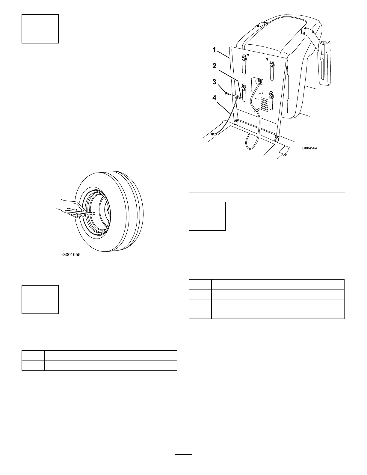
Figure2
1.Seatbase
2.Bolt(3/8x1inch)4.Nut(3/8inch)
3.Lanyard
Figure1
2
InstallingtheSeatLanyard
Partsneededforthisprocedure:
1
Bolt(3/8x1inch)
1
Nut(3/8inch)
Procedure
1.Removethenut,washer,andboltfromthelanyard.
2.Tilttheseatdownwardandalignthelanyardtothe
holeintheseatbase.
3.Installthelanyardtotheseatbasewithabolt(3/8x
1inch)andnut(3/8inch).
3
InstallingtheMotionControl
Levers
Partsneededforthisprocedure:
1Rightcontrollever
1
Leftcontrollever
4
Bolt(3/8x1inch)(2areassembled)
4
Curvedwasher(3/8inch)(2areassembled)
Procedure
Note:Therearetwocontrolleverheightoptions
available.Installthecontrolleverinthetoptwoholes
forthehighpositionandthebottomtwoholesforthe
lowposition.
1.Removethebottombolt(3/8x1inch)andcurved
washer(3/8inch)fromthemotioncontrollever.
Loosentheupperbolt(3/8x1inch)andcurved
washer(3/8inch)thatareinstalledintheposts.
2.Positiontheleversothebottomholealignswiththe
holeinthecontrolarmshaft.Looselyinstallthe
controlleverstotheoutsideoftheposts.
2
Page 3
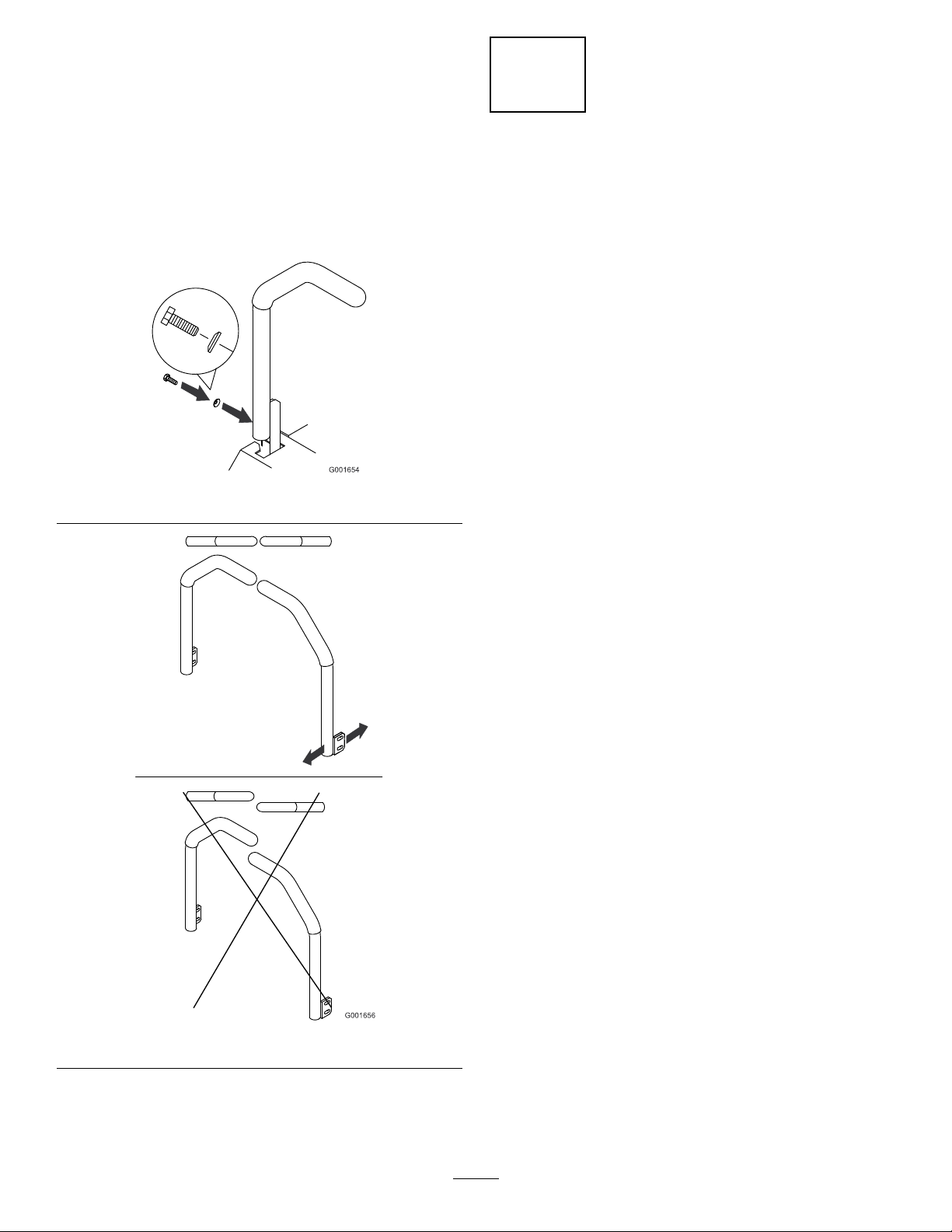
3.Raisetheleverstotheneutralpositionandalign
thembyslidingthemforwardorbackwardand
tightenthebolts.
4.Iftheendsofthelevershitagainsteachwhenrotated
intothedriveposition,movethemtotheneutral
positionandcarefullybendthemoutward.
5.Movethembacktothedrivepositionandcheckfor
clearance.
6.Repeatifnecessary.
Figure3
4
AddingFueltotheMachine
NoPartsRequired
Procedure
Note:Makesurebothfueltanksarehalffullwhenrst
startingthemachine.Thiswillpreventairgettinginto
thefuelsystemandcausingstartingproblems.
Addfueltothemachinebeforestartingit.Refertoyour
Operator’sManual.forthecorrectfuelandprocedure.
Figure4
3
Page 4

5
6
ChargingtheBattery
NoPartsRequired
Procedure
Chargingthebatteryproducesgassesthatcan
explodeandcauseseriousinjury.
•Keepcigarettes,sparksandamesaway
fromthebattery.
•Makesuretheignitionswitchisoff.
•Ventilatewhenchargingorusingthebattery
inanenclosedspace.
Important:Donotrunthemachinewiththe
batterydisconnected;electricaldamagemayoccur
totheengine.
CheckingtheMachinefor
Grease
Partsneededforthisprocedure:
1tube
Procedure
1.Removethebeltcovers.
2.Checktheidlerarmforgrease.
3.Checkthegreaseforthespindlebearings.Ifneeded,
4.Installthebeltcovers.
5.Tilttheseatforward.
6.Checkthepumpdrivebeltidlerarmforgrease.
Number2generalpurposelithiumbaseor
molybdenumbasegrease.(Purchaseseparately.)
addgreaseuntilitcomesoutofthelowerseals.
Chargethebattery.RefertotheOperator’ sManualfor
instructions.
Figure5
Figure6
4
Page 5

7
CheckingtheEngineOilLevel
NoPartsRequired
Procedure
Beforeyoustarttheengineandusethemachine,check
theoillevelintheenginecrankcase;refertoChecking
OilLevelinOperator’sManual.
8
PreparingtheSideDischarge
Chute
NoPartsRequired
Figure7
1.Cap3.Colduidlevel-full
2.Bafe4.Hotuidlevel-full
Procedure
Removetheplastictieholdingthesidedischargechute
upandlowerthechuteintoplace.
9
CheckingtheHydraulicOil
NoPartsRequired
Procedure
1.Starttheengineanddrivethemachineforwardand
backwardforafewminutestoallowanyextraairto
purgeoutofthehydraulicsystem.
2.Positionthemachineonalevelsurface.
3.DisengagethePTO,movethemotioncontrollevers
totheneutrallockedposition,andsettheparking
brake.
4.Stoptheengine,removethekey,andwaitforall
movingpartstostopbeforeleavingtheoperating
position.
5.Checktheexpansiontankandifnecessaryadd
hydraulicoiltothecoldlineonthesideofthetank.
6.Replacethetankcap,butdonotovertighten.
5
Page 6

10
CheckingtheMachineBeforeDeliverytotheCustomer
NoPartsRequired
Procedure
Beforedeliveringthemachinetothecustomer,ensurethatyouperformorhaveperformedtheprocedureslistedin
thefollowingtableandinitialeachwhennished.RefertotheOperator’sManualforinstructionsonperforming
theseprocedures.
Initial
Checkthetirepressure.
Checkthelevelofthemower.
Checktheengineoillevel.
Checkthehydraulicuidlevel.
Checktheoperationoftheparkingbrake.
Ensurethatthemachinetrackscorrectly;refertotheOperator’sManualfortheadjustmentprocedure.
Checkthesafetyinterlocksystem;refertotheOperator’sManual.
EnsurethatthePTOworks.
Checkallfastenersyouinstalledtoensurethattheyaretight.
Whenyounishsettingupthemachine,signanddateinthespaceprovidedbelow:
Signature:Date:
CheckProcedure
6
Page 7

11
DeliveringtheMachinetotheCustomer
Partsneededforthisprocedure:
1
Operator’sManual
1
PartsCatalog
1
EngineOwner’sManual
1
RegistrationCard
1
SafetyVideo
2Key
Procedure
Atdelivery,completetheitemslistedinthefollowingtableandinitialeachwhennished.
ModelNo.SerialNo.
7
Page 8

DealerInitial
CustomerInitialCheckProcedure
Showthecustomerwherethefollowingfeaturesarelocatedandhowtheyfunction:
Fueltankcaps
Oilllcap/Oildipstick
Engineoillter
Engineoildrain
Fuellters
Airlter
Hydraulicuidreservoir
Hydrauliclters
Battery
Ignitionswitch
Throttlelever
Powertakeoffswitch(PTO)
Motioncontrollevers
Parkingbrake
Mowerheight-of-cut
Adjustableseat
Hydraulicbypassvalves
RefertotheOperator’sManualtopointoutsafetyprocedures,operation,and
maintenanceprocedures.
ReviewthewarrantystatementasshownintheOperator’sManual.
Describethepostsaleserviceproceduresforyourstore.
Assistthecustomerinllingoutandmailingtheregistrationcardorregisteronlineat
www.T oro.com
MakesurethatthecustomerreceivestheOperator’sManual,PartsCatalog,andEngine
Owner’sManual,SetUpInstructions,andsafetyvideo.
Assistthecustomerinloadingthemower.
Note:Whenyou,thedealerrepresentative,havenisheddeliveringthemachinetothecustomer,signanddatein
thespaceprovidebelowandkeepacopyofthispagefordealerrecords.
Signature:Date:
Signature:Date:
8
 Loading...