

Page 1

TORO TIMECUTTER Z SERVICE MANUAL
Table of Contents – Page 1 of 2
QUICK REFERENCE
SAFETY INFORMATION
GENERAL INFORMATION
THINK SAFETY FIRST
SPECIFICATIONS
ENGINE SPECIFICATIONS - (Z16-44 & Z17-44)
ENGINE SPECIFICATIONS - (Z17-52 & Z18-52)
BOLT TORQUES
MAINTENANCE SCHEDULE
Z16-44
Z17-44 & Z17-52
Z18-52
MODEL/SERIAL NUMBER LOCATION
GREASING AND LUBRICATION
SERVICE INTERVAL/SPECIFICATION
LUBRICATION POINTS
ENGINE
BRIGGS & STRATTON ENGINE
KOHLER ENGINE
KAWASAKI ENGINE
BRIGGS & STRATTON AIR CLEANER
KOHLER AIR CLEANER
KAWASAKI AIR CLEANER
SPARK PLUG
ENGINE REMOVE AND REPLACE
TRANSAXLE
TROUBLESHOOTING CHECKLIST
FLUIDS
REMOVE AND REPLACE TRANSAXLE
REASSEMBLY
CONTROL HANDLE-RETURN TO NEUTRAL ADJUSTMENT
PURGING THE SYSTEM
NEUTRAL ADJUSTMENT
TRACKING ADJUSTMENT
CONTROL HANDLE ADJUSTMENT
CHASSIS
REMOVE AND REPLACE DAMPERS
REMOVE AND REPLACE CONTROL LINKAGE
REPLACE CONTROL LINKAGE
REMOVE AND REPLACE BRAKE LINKAGE
REPLACE BRAKE LINKAGE
PARKING BRAKE ADJUSTMENT
REPLACE TRACTION BELT
Page 2

TORO TIMECUTTER Z SERVICE MANUAL
Table of Contents – Page 2 of 2
MOWER DECKS: 44” AND 52” DECK ASSEMBLIES
BELT REMOVAL AND REPLACEMENT
MOWER DECK REMOVE AND REPLACE
MOWER DECK SIDE TO SIDE ADJUSTMENT
MOWER DECK FRONT TO REAR ADJUSTMENT
SPINDLE BEARING REPLACEMENT
ELECTRICAL SYSTEMS
SAFETY INTERLOCK SYSTEM
INTERLOCK COMPONENTS
ELECTRICAL COMPONENTS
ELECTRIC CLUTCH
ELECTRICAL SCHEMATICS
BRIGGS & STRATTON
KAWASAKI
KOHLER
Page 3

TimeCutter® Z
TimeCutter® ZX
Service Manual
Page 4

ABOUT THIS MANUAL
This service manual was written expressly for Toro service technician. The Toro Company has made every effort
to make the information in this manual complete and correct.
Basic mechanical/electrical skills are assumed. The Table of Contents lists the systems and the related topics
covered in this manual.
For additional information on the electrical system, please refer to the Toro Electrical Demystification Guide (492-
4404). For information on the hydrostatic drive units, refer to the Integrated Zero-Turn Transaxle Service and
Repair Manual (492-4737). For information specific to the engines used on this unit, refer to the appropriate
engine manufacturer’s service and repair instructions.
We are hopeful that you will find this manual a valuable addition to your service shop. If you have any questions or
comments regarding this manual, please contact us at the following address:
The Toro Company
Consumer Service Training Department
8111 Lyndale Avenue South
Bloomington, MN 55420
The Toro Company reserves the right to change product specifications or this manual without notice.
The automatic transmission and transaxle are sophisticated pieces of machinery. Maintain strict cleanliness
control during all stages of service and repair. Cover or cap all hose ends and fittings whenever they are exposed.
Even a small amount of dirt or other contamination can severely damage the system.
Copyright© All Rights Reserved
©2001 The Toro Company
Page 5

QUICK REFERENCE SECTION
TABLE OF CONTENTS
Safety Information . . . . . . . . . . . . . . . . . . . . . . . . . . . . . . . . . . . . . . . . . . . . .
Specifications . . . . . . . . . . . . . . . . . . . . . . . . . . . . . . . . . . . . . . . . . . . . . . . . .
Maintenance . . . . . . . . . . . . . . . . . . . . . . . . . . . . . . . . . . . . . . . . . . . . . . . . . . .
SERVICE SECTION
Model/Serial Number . . . . . . . . . . . . . . . . . . . . . . . . . . . . . . . . . . . . . . . . . . . . .
Greasing and Lubrication. . . . . . . . . . . . . . . . . . . . . . . . . . . . . . . . . . . . . . . . . .
Engine . . . . . . . . . . . . . . . . . . . . . . . . . . . . . . . . . . . . . . . . . . . . . . . . . . . . . . . .
Transaxle . . . . . . . . . . . . . . . . . . . . . . . . . . . . . . . . . . . . . . . . . . . . . . . . . . . . . .
1a
1b
1c
2
3
4
5
Chassis . . . . . . . . . . . . . . . . . . . . . . . . . . . . . . . . . . . . . . . . . . . . . . . . . . . . . . .
Mower Decks . . . . . . . . . . . . . . . . . . . . . . . . . . . . . . . . . . . . . . . . . . . . . . . . . . .
Electrical Systems . . . . . . . . . . . . . . . . . . . . . . . . . . . . . . . . . . . . . . . . . . . . . . .
6
7
8
TimeCutter™ Z Service Manual 1 - 1
Page 6

QUICK REFERENCE
SAFETY INFORMATION
General Information. . . . . . . . . . . . . . . . . . . . . . . . . . . . . . . . . . . . . . . . . . . . . 1 - 3
Think Safety First. . . . . . . . . . . . . . . . . . . . . . . . . . . . . . . . . . . . . . . . . . . . . . . 1 - 3
SPECIFICATIONS
Engine Specifications - (Z16-44 & Z17-44) . . . . . . . . . . . . . . . . . . . . . . . . . . . 1 - 4
Engine Specifications - (Z17-52 & Z18-52) . . . . . . . . . . . . . . . . . . . . . . . . . . . 1 - 5
BOLT TORQUES . . . . . . . . . . . . . . . . . . . . . . . . . . . . . . . . . . . . . . . . . . . . . . . . . 1 - 6
MAINTENANCE SCHEDULE
Table of Contents
Z16-44 . . . . . . . . . . . . . . . . . . . . . . . . . . . . . . . . . . . . . . . . . . . . . . . . . . . . . . . 1 - 7
Z17-44 & Z17-52 . . . . . . . . . . . . . . . . . . . . . . . . . . . . . . . . . . . . . . . . . . . . . . . 1 - 8
Z18-52 . . . . . . . . . . . . . . . . . . . . . . . . . . . . . . . . . . . . . . . . . . . . . . . . . . . . . . 1 - 9
1 - 2 TimeCutter™ Z Service Manual
Page 7

SAFETY INFORMATION
This symbol means WARNING or
PERSONAL SAFETY INSTRUCTION
- read the instruction because it has to
do with your safety. Failure to comply
with the instruction may result in
personal injury or even death.
This manual is intended as a service and repair manual
only. The safety instructions provided herein are for
troubleshooting, service, and repair of the TimeCutter Z
zero radius tractor. The TimeCutter Z zero radius
THINK SAFETY FIRST
Avoid unexpected starting of engine...
Always turn off the engine and disconnect the spark
plug wire(s) before cleaning, adjusting, or repair.
Avoid lacerations and amputations...
Stay clear of all moving parts whenever the engine is
running. Treat all normally moving parts as if they were
moving whenever the engine is running or has the
potential to start.
tractor and attachment operator’s manuals contain
safety information and operating tips for safe operating
practices. Operator’s manuals are available through
your Toro parts source or:
1a
The Toro Company
Publications Department
8111 Lyndale Avenue South
Bloomington, MN 55420
Avoid injury from batteries...
Battery acid is poisonous and can cause burns. Avoid
contact with skin, eyes, and clothing. Battery gases can
explode. Keep cigarettes, sparks, and flames away
from the battery.
Avoid injury due to inferior parts...
Use only original equipment parts to ensure that
important safety criteria are met.
Avoid burns...
Do not touch the engine, muffler, or other components
which may increase in temperature during operation,
while the unit is running or shortly after it has been
running.
Avoid fires and explosions...
Avoid spilling fuel and never smoke while working with
any type of fuel or lubricant. Wipe up any spilled fuel or
oil immediately. Never remove the fuel cap or add fuel
when the engine is running. Always use approved,
labeled containers for storing or transporting fuel and
lubricants.
Avoid asphyxiation...
Never operate an engine in a confined area without
proper ventilation.
Avoid injury to bystanders...
Always clear the area of bystanders before starting or
testing powered equipment.
Avoid injury due to projectiles...
Always clear the area of sticks, rocks, or any other
debris that could be picked up and thrown by the
powered equipment.
Avoid modifications...
Never alter or modify any part unless it is a factory
approved procedure.
Avoid unsafe operation...
Always test the safety interlock system after making
adjustments or repairs on the machine. Refer to the
Electrical section in this manual for more information.
TimeCutter™ Z Service Manual 1 - 3
Page 8

SPECIFICATIONS
Specifications
ENGINE:
High Idle 3400 ± 100 RPM 3400 ± 100 RPM
Low Idle 1400 RPM 1400 RPM
1b
FUEL SYSTEM:
TRACTION SYSTEM:
Manufacturer Briggs & Stratton Kohler
Horsepower (kW) 16.5 HP (12.3kW) @ 3600 RPM 17 HP (12.7 kW) @ 3600 RPM
Capacity 5 Gallon (18.9 L) 5 Gallon (18.9 L)
Transaxles Twin Hydro-Gear IZT Hydrostatic
Transaxle Drive Belt drive with self-tensioning system Belt drive with self-tensioning system
Z16-44 Z17-44
Fuel Unleaded Gasoline 87 octane min. Unleaded Gasoline 87 octane min.
Twin Hydro-Gear IZT Hydrostatic
Transaxles
Transaxles
Ground Speed Infinite, 0 to 6.5 MPH (10.5-km/hr) forward
0 to 3.4 MPH (5.5-km/hr) reverse
TIRES:
Rear Drive Tires 18x10-8 4 ply with “Multitrac CS” Tread 18x10-8 4 ply with “Multitrac CS” Tread
Front Caster Tires 410/350 x 4 - 4.25 IS with “sawtooth” tread 410/350 x 4 - 4.25 IS with “sawtooth” tread
Tire Pressure 13 psi (90 kPa) rear, 35 psi (241 kPa) front 13 psi (90 kPa), rear 35 psi (241 kPa) front
ELECTRICAL
SYSTEM:
Battery Voltage 12 volt, negative ground 12 volt, negative ground
Battery Type BCI Group U1 BCI Group U1
DIMENSIONS:
Wheel Base 52.1 in. (132.3 cm) center of caster to
center of drive tires
Overall Width 55 in. (139.7 cm) with deck deflector down
46.6 in. (118.4 cm) gate width with deck
deflector up
Overall Length 77.5 in. (196.9 cm) 77.5 in. (196.9 cm)
WEIGHT:
Net Weight 635 lbs. (approx.) 635 lbs. (approx.)
Infinite, 0 to 6.5 MPH (10.5-km/hr) forward
0 to 3.4 MPH (5.5-km/hr) reverse
52.1 in. (132.3 cm) center of caster to
center of drive tires
55 in. (139.7 cm) with deck deflector down
46.6 in. (118.4 cm) gate width with deck
deflector up
HEIGHT OF CUT:
Adjusts from 1.5” (3.8 cm) to
4.5” (11.4 cm) (7 positions)
1 - 4 TimeCutter™ Z Service Manual
Adjusts from 1.5” (3.8 cm) to
4.5” (11.4 cm) (7 positions)
Page 9

Specifications (cont’d)
ENGINE:
High Idle 3400 ± 100 RPM 3400 ± 100 RPM
Low Idle 1400 RPM 1400 RPM
Manufacturer Kohler Kawasaki
Horsepower (kW) 17 HP (12.7kW) @ 3600 RPM 18 HP (13.4kW) @ 3600 RPM
Fuel Unleaded Gasoline 87 octane min. Unleaded Gasoline 87 octane min.
FUEL SYSTEM:
Capacity 5 Gallon (18.9 L) 5 Gallon (18.9 L)
TRACTION SYSTEM:
Transaxles Twin Hydro-Gear IZT Hydrostatic
Transaxles
Transaxle Drive Belt drive with self-tensioning system Belt drive with self-tensioning system
SPECIFICATIONS
Z17-52 Z18-52
1b
Twin Hydro-Gear IZT Hydrostatic
Transaxles
Ground Speed Infinite, 0 to 6.5 MPH (10.5-km/hr) forward
TIRES:
Rear Drive Tires 18x10-10-10.5 4 ply with “Multitrac CS”
Front Caster Tires 410/350 x 4 - 4.25 IS with “sawtooth” tread 410/350 x 4 - 4.25 IS with “sawtooth” tread
Tire Pressure 13 psi (90 kPa) rear, 35 psi (241 kPa) front 13 psi (90 kPa) rear, 35 psi (241 kPa) front
ELECTRICAL SYSTEM:
Battery Voltage 12 volt, negative ground 12 volt, negative ground
Battery Type BCI Group U1 BCI Group U1
DIMENSIONS:
Wheel Base 52.1 in. (132.3 cm) center of caster to
Overall Width 65 in. (165.1 cm) with deck deflector down
Overall Length 77.5 in. (196.9 cm) 77.5 in. (196.9 cm)
WEIGHT:
Net Weight 680 lbs. (approx.) 680 lbs. (approx.)
0 to 3.4 MPH (5.5-km/hr) reverse
Tread
center of drive tires
58 in. (147.3 cm) gate width with deck
deflector up
Infinite, 0 to 6.5 MPH (10.5-km/hr) forward
0 to 3.4 MPH (5.5-km/hr) reverse
18x10-10-10.5 4 ply with “Multitrac CS”
Tread
52.1 in. (132.3 cm) center of caster to
center of drive tires
65 in. (165.1 cm) with deck deflector down
58 in. (147.3 cm) gate width with deck
deflector up
HEIGHT OF CUT:
Adjusts from 1.5” (3.8 cm) to 4.5” (11.4 cm)
(7 positions)
TimeCutter™ Z Service Manual 1 - 5
Adjusts from 1.5” (3.8 cm) to 4.5” (11.4 cm)
(7 positions)
Page 10

1b
SPECIFICATIONS
Specifi cations cont.
ZX 17K-44 ZX 17-44
Engine: 17 hp Kohler® OHV, CV490S 17 hp Briggs & Stratton OHV, 31F777
High Idle 3400 + 100 RPM 3400 + 100 RPM
Low Idle 1400 RPM N/A
Horse Power 17 (12.7kW) @3600 RPM 17 (12.7kW) @3600 RPM
Cubic Centimeter’s (cc’s) 490 Dispacement 500 Dispacement
Fuel Unleaded Gasoline 87 octane min. Unleaded Gasoline 87 octane min.
Oil Capacity 2 qts. (1.9 L) 1.75 qt. (1.7 L)
Charge coil 12v - 15 amp 12v - 16 amp
Construction:
Front Frame Welded 1x2x.120” structural steel tube Welded 1x2x.120” structural steel tube
Rear Frame Welded 7 & 10 ga. High strength steel Welded 7 & 10 ga. High strength steel
Frame Assembly Front & rear frames bolted together. Front & rear frames bolted together.
Deck Right side discharge, 44 in. cut, three
blade mid-mounted rotary. Drawn 13
gauge steel with welded mounting
brackets and gauge wheel brackets.
Frame supported.
Right side discharge, 44 in. cut, three
blade mid-mounted rotary. Drawn 13
gauge steel with welded mounting
brackets and gauge wheel brackets.
Frame supported.
Fuel System: Single fuel tank fender type mounted on
the left side.
Capacity 5 Gallons (18.9 L)
Fuel tank shut off
In-line fuel fi lter
Traction System:
Transaxles Twin Hydro-Gear IZT Hydrostatic
Transaxles
Transaxle Drive Belt Drive with self-tensioning system Belt Drive with self-tensioning system
Ground speed forward Infi nite, 0 to 6.5-MPH (10.5-km/hr) Infi nite, 0 to 6.5-MPH (10.5-km/hr)
Ground speed reverse 0 to 3.4-MPH (5.5-km/hr) 0 to 3.4-MPH (5.5-km/hr)
Transport rods Allows unit to be moved without engine
running.
Attachment Drive:
Clutch Electric Electric
Type Vertical Drive with Single Deep B-Groove
Pulley
Single fuel tank fender type mounted on
the left side.
5 Gallons (18.9 L)
Fuel tank shut off
In-line fuel fi lter
Twin Hydro-Gear IZT Hydrostatic
Transaxles
Allows unit to be moved without engine
running.
Vertical Drive with Single Deep B-Groove
Pulley
A1-6 TimeCutter ZX Service Manual
Page 11

SPECIFICATIONS
Specifi cations cont.
ZX 17K-44 ZX 17-44
Tires:
Rear Drive Tires 18x10-8 4 ply with “Multitrac CS” Tread 18x10-8 4 ply with “Multitrac CS” Tread
Front Castor Tires 410/350x4 - 4.25 IS with “sawtooth” tread 410/350x4 - 4.25 IS with “sawtooth” tread
Tire Pressure 13 psi (90kPa) rear, 35 psi (241kPa) front 13 psi (90kPa) rear, 35 psi (241kPa) front
Electrical System:
Battery voltage 12 volt negative ground. 12 volt negative ground.
Fused (1) 30 amp blade type main.
(1) 25 amp blade type charge system.
(1) 10 amp included with optional light kit.
Dimensions:
Wheel Base 52.1” (132.3cm) center of castor wheel to
center of drive tires.
Width 43” (109.2cm) outside rear tires. 43” (109.2cm) outside rear tires.
Overall Width 55” (139.7cm) with deck defl ector down.
46.6” (188.4cm) Gate width with deck
defl ector up.
Overall Length 77.5” (196.9cm) 77.5” (196.9cm)
Overall Height 40” (101.6cm) 40” (101.6cm)
Track Width 35.2” (89.4cm) center to center of rear
tires.
30.4” (77.2cm) center to center of castor
tires.
Deck Width 55” (139.7cm) with defl ector down. 55” (139.7cm) with defl ector down.
(1) 30 amp blade type main.
(1) 25 amp blade type charge system.
(1) 10 amp included with optional light kit.
52.1” (132.3cm) center of castor wheel to
center of drive tires.
55” (139.7cm) with deck defl ector down.
46.6” (188.4cm) Gate width with deck
defl ector up.
35.2” (89.4cm) center to center of rear
tires.
30.4” (77.2cm) center to center of castor
tires.
1b
Weight: 635 lbs. (288kg) (estimated) 635 lbs. (288kg) (estimated)
Height of Cut: Adjusts from 1.5” to 4.5” (7 postions) Adjusts from 1.5” to 4.5” (7 postions)
Tip Speed: 18,160 ft/min @ 3400 RPM nominal
18,770 ft/min @ 3500 RPM max
18,160 ft/min @ 3400 RPM nominal
18,770 ft/min @ 3500 RPM max
A1-7TimeCutter ZX Service Manual
Page 12

1b
SPECIFICATIONS
Specifi cations cont.
ZX 17-52 ZX 18-52
Engine: 17 hp Kohler® OHV, CV490S 18 hp Kawasaki OHV, FH531V
High Idle 3400 + 100 RPM 3400 + 100 RPM
Low Idle 1400 RPM 1400 RPM
Horse Power 17 (12.7kW) @3600 RPM 18 HP (13.4kW) @3600 RPM
Cubic Centimeter’s (cc’s) 490 Dispacement 494 Displacement
Fuel Unleaded Gasoline 87 octane min. Unleaded Gasoline 87 octane min.
Oil Capacity 2 qts. (1.9 L) 1.9 qts (1.8 L)
Charge coil 12v - 15 amp 12v - 13 amp
Construction:
Front Frame Welded 1x2x.120” structural steel tube Welded 1x2x.120” structural steel tube
Rear Frame Welded 7 & 10 ga. High strength steel Welded 7 & 10 ga. High strength steel
Frame Assembly Front & rear frames bolted together. Front & rear frames bolted together.
Deck Right side discharge, 52 in. cut, three
blade mid-mounted rotary. Drawn 12
gauge steel with welded mounting
brackets and gauge wheel brackets.
Frame supported.
Right side discharge, 52 in. cut, three
blade mid-mounted rotary. Drawn 12
gauge steel with welded mounting
brackets and gauge wheel brackets.
Frame supported.
Fuel System: Single fuel tank fender type mounted on
the left side.
Capacity 5 Gallons (18.9 L)
Fuel tank shut off
In-line fuel fi lter
Traction System:
Transaxles Twin Hydro-Gear IZT Hydrostatic
Transaxles
Transaxle Drive Belt Drive with self-tensioning system Belt Drive with self-tensioning system
Ground speed forward Infi nite, 0 to 6.5-MPH (10.5-km/hr) Infi nite, 0 to 6.5-MPH (10.5-km/hr)
Ground speed reverse 0 to 3.4-MPH (5.5-km/hr) 0 to 3.4-MPH (5.5-km/hr)
Transport rods Allows unit to be moved without engine
running.
Attachment Drive:
Clutch Electric Electric
Type Vertical Drive with Single Deep B-Groove
Pulley
Single fuel tank fender type mounted on
the left side.
5 Gallons (18.9 L)
Fuel tank shut off
In-line fuel fi lter
Twin Hydro-Gear IZT Hydrostatic
Transaxles
Allows unit to be moved without engine
running.
Vertical Drive with Single Deep B-Groove
Pulley
A1-8 TimeCutter ZX Service Manual
Page 13

SPECIFICATIONS
Specifi cations cont.
ZX 17-52 ZX 18-52
Tires:
Rear Drive Tires 18x10-8 4 ply with “Multitrac CS” Tread 18x10-10.5 4 ply with “Multitrac CS”
Tread
Front Castor Tires 410/350x4 - 4.25 IS with “sawtooth” tread 410/350x4 - 4.25 IS with “sawtooth” tread
Tire Pressure 13 psi (90kPa) rear, 35 psi (241kPa) front 13 psi (90kPa) rear, 35 psi (241kPa) front
Electrical System:
Battery voltage 12 volt negative ground. 12 volt negative ground.
Fused (1) 30 amp blade type main.
(1) 25 amp blade type charge system.
(1) 10 amp included with optional light kit.
Dimensions:
Wheel Base 52.1” (132.3cm) center of castor wheel to
center of drive tires.
Width 47.6” (120.9cm) outside rear tires. 47.6” (120.9cm) outside rear tires.
Overall Width 65” (165.1cm) with deck defl ector down.
58” (147.3cm) Gate width with deck
defl ector up.
Overall Length 77.5” (196.9cm) 77.5” (196.9cm)
Overall Height 41” (104.1cm) 41” (104.1cm)
Track Width 37.5” (95.3cm) center to center of rear
tires.
30.4” (77.2cm) center to center of castor
tires.
Deck Width 65” (165.1cm) with deck defl ector down. 65” (165.1cm) with defl ector down.
(1) 30 amp blade type main.
(1) 25 amp blade type charge system.
(1) 10 amp included with optional light kit.
52.1” (132.3cm) center of castor wheel to
center of drive tires.
65” (165.1cm) with deck defl ector down.
58” (147.3cm) Gate width with deck
defl ector up.
37.5” (95.3cm) center to center of rear
tires.
30.4” (77.2cm) center to center of castor
tires.
1b
Weight: 680 lbs. (308.4kg) (estimated) 680 lbs. (308.4kg) (estimated)
Height of Cut: Adjusts from 1.5” to 4.5” (7 postions) Adjusts from 1.5” to 4.5” (7 postions)
Tip Speed: 17,410 ft/min @ 3400 RPM nominal
17,980 ft/min @ 3400 RPM max
17,410 ft/min @ 3400 RPM nominal
17,980 ft/min @ 3500 RPM max
A1-9TimeCutter ZX Service Manual
Page 14

1b
SPECIFICATIONS
Specifi cations cont.
ZX 18-52 ZX 19-52
Engine: 18 hp Kohler® CV4925 19 hp Kawasaki OHV, FH580V
High Idle 3400 + 100 RPM 3400 + 100 RPM
Low Idle 1400 RPM 1400 RPM
Horse Power 18 (13.4kW) @3600 RPM 19 HP (14.2kW) @3600 RPM
Cubic Centimeter’s (cc’s) 490 Displacement 585 Displacement
Fuel Unleaded Gasoline 87 octane min. Unleaded Gasoline 87 octane min.
Oil Capacity 2 qts. (1.9 L) 1.9 qts. (1.8 L)
Charge coil 12v - 15 amp 12v - 15 amp
Construction:
Front Frame Welded 1x2x.120” structural steel tube Welded 1x2x.120” structural steel tube
Rear Frame Welded 7 & 10 ga. High strength steel Welded 7 & 10 ga. High strength steel
Frame Assembly Front & rear frames bolted together. Front & rear frames bolted together.
Deck Right side discharge, 52” cut, three blade
mid-mounted rotary. Drawn 12 gauge
steel with welded mounting brackets and
gauge wheel brackets. Frame supported.
Right side discharge, 52” cut, three blade
mid-mounted rotary. Drawn 12 gauge
steel with welded mounting brackets and
gauge wheel brackets. Frame supported.
Fuel System: Single fuel tank fender type mounted on
the left side.
Capacity 5 Gallons (18.9 L)
Fuel tank shut off
In-line fuel fi lter
Traction System:
Transaxles Twin Hydro-Gear IZT Hydrostatic
Transaxles
Transaxle Drive Belt Drive with self-tensioning system Belt Drive with self-tensioning system
Ground speed forward Infi nite, 0 to 6.5-MPH (10.5-km/hr) Infi nite, 0 to 6.5-MPH (10.5-km/hr)
Ground speed reverse 0 to 3.4-MPH (5.5-km/hr) 0 to 3.4-MPH (5.5-km/hr)
Transport rods Allows unit to be moved without engine
running.
Attachment Drive:
Clutch Electric Electric
Type Vertical Drive with Single Deep B-Groove
Pulley
Single fuel tank fender type mounted on
the left side.
5 Gallons (18.9 L)
Fuel tank shut off
In-line fuel fi lter
Twin Hydro-Gear IZT Hydrostatic
Transaxles
Allows unit to be moved without engine
running.
Vertical Drive with Single Deep B-Groove
Pulley
A1-10 TimeCutter ZX Service Manual
Page 15

SPECIFICATIONS
Specifi cations cont.
ZX 18-52 ZX 19-52
Tires:
Rear Drive Tires 18x10.5-10 4 ply with “Multitrac CS”
Tread
Front Castor Tires 410/350x4 with “sawtooth” tread 410/350x4 with “sawtooth” tread
Tire Pressure 13 psi (90kPa) rear, 35 psi (241kPa) front 13 psi (90kPa) rear, 35 psi (241kPa) front
Electrical System:
Battery voltage 12 volt negative ground. 12 volt negative ground.
Fused (1) 30 amp blade type main.
(1) 25 amp blade type charge system.
(1) 10 amp included with optional light kit.
Dimensions:
Wheel Base 52.1” (132.3cm) center of castor wheel to
center of drive tires.
Width 47.6” (120.9cm) outside rear tires. 47.6” (120.9cm) outside rear tires.
Overall Width 65” (165.1cm) with deck defl ector down.
58” (147.3cm) Gate width with deck
defl ector up.
Overall Length 77.5” (196.9cm) 77.5” (196.9cm)
Overall Height 41” (104.1cm) 41” (104.1cm)
Track Width 37.5” (95.3cm) center to center of rear
tires.
30.4” (77.2cm) center to center of castor
tires.
Deck Width 65” (165.1cm) with defl ector down. 66” (165.1cm) with defl ector down.
18x10.5-10 4 ply with “Multitrac CS”
Tread
(1) 30 amp blade type main.
(1) 25 amp blade type charge system.
(1) 10 amp included with optional light kit.
52.1” (132.3cm) center of castor wheel to
center of drive tires.
65” (165.1cm) with deck defl ector down.
58” (147.3cm) Gate width with deck
defl ector up.
37.5” (95.3cm) center to center of rear
tires.
30.4” (77.2cm) center to center of castor
tires.
1b
Weight: 680 lbs. (308.4kg) (estimated) 680 lbs. (308.4kg) (estimated)
Height of Cut: Adjusts from 1.5” to 4.5” (7 postions) Adjusts from 1.5” to 4.5” (7 postions)
Tip Speed: 17,500 ft/min @ 3400 RPM nominal
18,070 ft/min @ 3500 RPM max
17,500 ft/min @ 3400 RPM nominal
18,070 ft/min @ 3500 RPM max
A1-11TimeCutter ZX Service Manual
Page 16

1b
SPECIFICATIONS
Specifi cations cont.
ZX 18-44 ZX 440
Engine: 18 hp Briggs & Stratton OHV, 31M777 18 hp Kohler® OHV, CV492S
High Idle 3400 + 100 RPM 3400 + 50/- 0 RPM
Low Idle 1400 RPM 1400 RPM
Horse Power 18 (13.4kW) @3600 RPM 10 HP (13.4kW) @ 3600 RPM
Cubic Centimeter’s (cc’s) 500 Displacement 490 Displacement
Fuel Unleaded Gasoline 87 octane min. Unleaded Gasoline 87 octane min.
Oil Capacity 1.75 qts. (1.7 L) 2 qts. (1.9 L)
Charge coil 12v - 16 amp 12v - 15 amp
Construction:
Front Frame Welded 1x2x.120” structural steel tube Welded 1x2x.120” structural steel tube
Rear Frame Welded 7 & 10 ga. High strength steel Welded 7 & 10 ga. High strength steel
Frame Assembly Front & rear frames bolted together. Front & rear frames bolted together.
Deck Right side discharge, 44” cut, three blade
mid-mounted rotary. Drawn 13 gauge
steel with welded mounting brackets and
gauge wheel brackets. Frame supported.
Right side discharge, 44” cut, three blade
mid-mounted rotary. Drawn 13 gauge
steel with welded mounting brackets and
gauge wheel brackets. Frame supported.
Fuel System: Single fuel tank fender type mounted on
the left side.
Capacity 5 Gallons (18.9 L)
Fuel tank shut off
In-line fuel fi lter
Traction System:
Transaxles Twin Hydro-Gear IZT Hydrostatic
Transaxles
Transaxle Drive Belt Drive with self-tensioning system Belt Drive with self-tensioning system
Ground speed forward Infi nite, 0 to 6.5-MPH (10.5-km/hr) Infi nite, 0 to 7.0-MPH (11.3-km/hr)
Ground speed reverse 0 to 3.4-MPH (5.5-km/hr) 0 to 3.4-MPH (5.5-km/hr)
Transport rods Allows unit to be moved without engine
running.
Attachment Drive:
Clutch Electric Electric
Type Vertical Drive with Single Deep B-Groove
Pulley
Single fuel tank fender type mounted on
the left side.
5 Gallons (18.9 L)
Fuel tank shut off
In-line fuel fi lter
Twin Hydro-Gear IZT Hydrostatic Transaxles with charge pumps & shock valves
Allows unit to be moved without engine
running.
Vertical Drive with Single Deep B-Groove
Pulley
A1-12 TimeCutter ZX Service Manual
Page 17

SPECIFICATIONS
Specifi cations cont.
ZX 18-44 ZX 440
Tires:
Rear Drive Tires 18x7.5-8 ply with “Multitrac CS” Tread 18x7.5-4 ply
Front Castor Tires 410/350x4 with “sawtooth” tread 410/350x4 “sawtooth” tread
Tire Pressure 13 psi (90kPa) rear, 35 psi (241kPa) front 13 psi (90kPa) rear, 35 psi (241kPa) front
Electrical System:
Battery voltage 12 volt negative ground. 12 volt negative ground.
Fused (1) 30 amp blade type main.
(1) 25 amp blade type charge system.
(1) 10 amp included with optional light kit.
Dimensions:
Wheel Base 52.1” (132.3cm) center of castor wheel to
center of drive tires.
Width 43” (109.2cm) outside rear tires. 43” (109.2cm) outside rear tires.
Overall Width 55” (139.7cm) with deck defl ector down.
46.6” (188.4cm) Gate width with deck
defl ector up.
Overall Length 77.5” (196.9cm) 77.5” (196.9cm)
Overall Height 40” (101.6cm) 40” (101.6cm)
Track Width 35.2” (89.4cm) center to center of rear
tires.
30.4” (77.2cm) center to center of castor
tires.
Deck Width 55” (139.7cm) with defl ector down. 60” (139.7cm) with deck defl ector down
(1) 30 amp blade type main.
(1) 25 amp blade type charge system.
(1) 10 amp included with optional light kit.
52.1” (132.3cm) center of castor wheel to
center of drive tires.
60” (139.7cm) with deck defl ector down
49” (118.4cm) Gate width with deck
defl ector up.
35.2” (89.4cm) center to center of rear
tires.
30.4” (77.2cm) center to center of castor
tires.
1b
Weight: 635 lbs. (288 kg) (estimated) 651 lbs. (295 kg) (estimated)
Height of Cut: Adjusts from 1.5” to 4.5” (7 postions) Adjusts from 1.5” to 4.5” (7 postions)
Tip Speed: 18,160 ft/min @ 3400 RPM nominal
18,770 ft/min @ 3500 RPM max
18,160 ft/min @ 3400 RPM nominal
18,770 ft/min @ 3500 RPM max
A1-13TimeCutter ZX Service Manual
Page 18

1b
SPECIFICATIONS
Specifi cations cont.
ZX 480 ZX 525
Engine: Briggs & Stratton Intek OHV, 441577 Kawasaki FH58V OHV
High Idle 3400 + 100 RPM 3400 + 100 RPM
Low Idle N/A 1400 RPM
Horse Power N/A N/A
Cubic Centimeter’s (cc’s) 725 Dispacement 585 Dispacement
Fuel Unleaded Gasoline 87 octane min. Unleaded Gasoline 87 octane min.
Oil Capacity 2 qts. (1.9 L) 1.9 qts. (1.8 L)
Charge coil 12v - 16 amp 12v - 13 amp
Construction:
Front Frame Welded 1x2x.120” structural steel tube Welded 1x2x.120” structural steel tube
Rear Frame Welded 7 & 10 ga. High strength steel Welded 7 & 10 ga. High strength steel
Frame Assembly Front & rear frames bolted together. Front & rear frames bolted together.
Deck Right side discharge, 48” cut, three
blade mid-mounted rotary. Drawn 12
gauge steel deck with gauge reinforced
plate and welded mounting brackets and
gauge.
Right side discharge, 44” cut, three blade
mid-mounted rotary. Drawn 12 gauge
steel with welded mounting brackets and
gauge wheel brackets. Frame supported.
Fuel System: Single fuel tank fender type mounted on
the left side.
Capacity 5 Gallons (18.9 L)
Fuel tank shut off
In-line fuel fi lter
Traction System:
Transaxles Twin Hydro-Gear IZT Hydrostatic Trans-
axles with charge pumps & shock valves.
Transaxle Drive Belt Drive with self-tensioning system Belt Drive with self-tensioning system
Ground speed forward Infi nite, 0 to 7.0-MPH (11.3-km/hr) Infi nite, 0 to 7.0-MPH (11.3-km/hr)
Ground speed reverse 0 to 3.4-MPH (5.5-km/hr) 0 to 3.4-MPH (5.5-km/hr)
Transport rods Allows unit to be moved without engine
running.
Attachment Drive:
Clutch Electric Electric
Type Vertical Drive with Single Deep B-Groove
Pulley
Single fuel tank fender type mounted on
the left side.
5 Gallons (18.9 L)
Fuel tank shut off
In-line fuel fi lter
Twin Hydro-Gear IZT Hydrostatic Transaxles with charge pumps & shock valves.
Allows unit to be moved without engine
running.
Vertical Drive with Single Deep B-Groove
Pulley
A1-14 TimeCutter ZX Service Manual
Page 19

SPECIFICATIONS
Specifi cations cont.
ZX 480 ZX 525
Tires:
Rear Drive Tires 18x10.5-4 ply 18x10.5-10 4 ply with “Multitrac CS”
Tread
Front Castor Tires 410/350x4 with “sawtooth” tread 410/350x4 with “sawtooth” tread
Tire Pressure 13 psi (90kPa) rear, 35 psi (241kPa) front 13 psi (90kPa) rear, 35 psi (241kPa) front
Electrical System:
Battery voltage 12 volt negative ground. 12 volt negative ground.
Fused (1) 30 amp blade type main.
(1) 25 amp blade type charge system.
(1) 25 amp blade type charge system.
Dimensions:
Wheel Base 52.1” (132.3cm) center of castor wheel to
center of drive tires.
Width 43” (109.2cm) outside rear tires. 47.6” (120.9cm) outside rear tires.
Overall Width 62.5” (158.8cm) with deck defl ector
down.
53.5” (135.9cm) Gate width with deck
defl ector up.
Overall Length 77.5” (196.9cm) 77.5” (196.9cm)
Overall Height 40” (101.6cm) 41” (101.6cm)
Track Width 35.2” (89.4cm) center to center of rear
tires.
30.4” (77.2cm) center to center of castor
tires.
Deck Width 62.5” (158.8cm) with defl ector down. 68” (165.1cm) with defl ector down.
(1) 30 amp blade type main.
(1) 25 amp blade type charge system.
(1) 10 amp (blade type) included with
optional light kit.
52.1” (132.3cm) center of castor wheel to
center of drive tires.
68” (165.1cm) with deck defl ector down.
55” (147.3cm) Gate width with deck
defl ector up.
37.5in. (95.3cm) center to center of rear
tires.
30.4” (77.2cm) center to center of castor
tires.
1b
Weight: 646 lbs. (293 kg) (estimated) 695 lbs. (315 kg) (estimated)
Height of Cut: Adjusts from 1.5” to 4.5” (7 postions) Adjusts from 1.5” to 4.5” (7 postions)
Tip Speed: 15,710 ft/min @ 3400 RPM nominal
16,170 ft/min @ 3400 RPM nominal
17,500 ft/min @ 3400 RPM nominal
18,070 ft/min @ 3500 RPM max
A1-15TimeCutter ZX Service Manual
Page 20

SPECIFICATIONS
Bolt Torques
Description Torque - 52” Torque - 44”
Blade to Spindle 80 - 100 ft·lb (109 - 136 N·m) 40 - 60 ft·lb (54 - 82 N·m)
Caster Bolts 77 - 95 ft·lb (105 - 130 N·m) 77 - 95 ft·lb (105 - 130 N·m)
Clutch Bolt 50 - 60 ft·lb (68 - 82 N·m) 50 - 60 ft·lb (68 - 82 N·m)
1b
Engine Mounting Bolts 120 - 180 ft·lb (164 - 246 N·m) 120 - 180 ft·lb (164 - 246 N·m)
Spindle Pulley Nuts 80 - 100 ft·lb (109 - 136 N·m) 50 - 75 ft·lb (68 - 102 N·m)
Wheel Lug Nuts 70 - 90 ft·lb (95.5 - 123 N·m) 70 - 90 ft·lb (95.5 - 123 N·m)
1 - 6 TimeCutter™ Z Service Manual
Page 21
MAINTENANCE
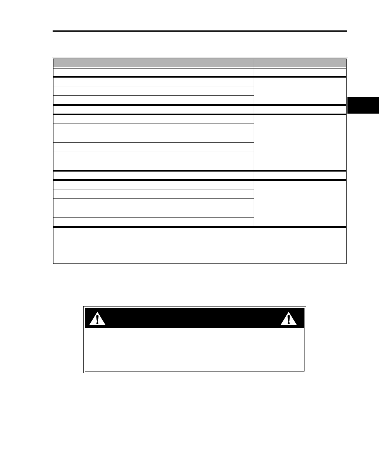
Maintenance Schedule (Z16-44)
Maintenance Procedure Service Interval
Change the engine oil After first use
Check the engine oil level
Each useCheck the safety system
Clean the mower housing
Check the cutting blades Every 5 hours
Grease all lubrication points
Oil the linkage bushings
Service the foam air cleaner
Check the belts for wear/cracks
Check the battery electrolyte
Check the tire pressure
Change the engine oil
Clean the cooling system
Service the paper air cleaner
Change the oil filter
Replace the fuel filter
Replace the spark plug(s)
Before Storage:
• Perform all maintenance procedures listed above.
• Drain the fuel tank.
• Charge the battery and disconnect the battery cables.
• Paint any chipped surfaces.
2
1
1
1
Every 25 hours
2
1
1
Every 50 hours
Every 100 hours
1c
1
More often in dusty, dirty conditions
2
More often when operating the engine under heavy load or in high temperatures
IMPORTANT: Refer to your engine operator’s manual for additional maintenance procedures.
CAUTION
If you leave the key in the ignition switch, someone could accidently start the
engine and seriously injury you or other bystanders.
Remove the key from the ignition and disconnect the wire from the spark
plug(s) before you do any maintenance. Set the wire aside so that it does not
accidentally contact the spark plug.
TimeCutter™ Z Service Manual 1 - 7
Page 22
MAINTENANCE
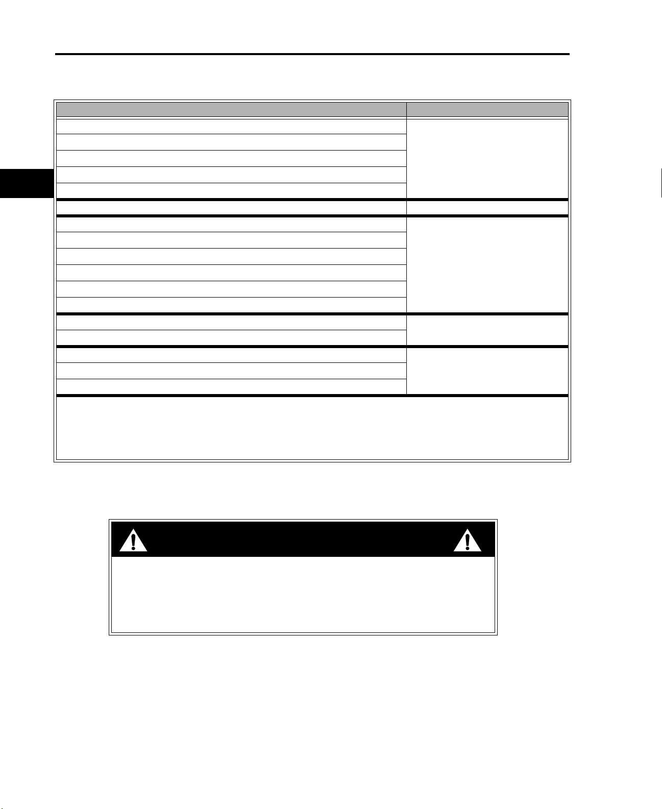
Maintenance Schedule (Z17-44 & Z17-52)
Maintenance Procedure Service Interval
Check the engine oil level
Check the safety system
1
1
1
1
1
1
1
1c
Clean the cooling system
Clean the mower housing
Check the air cleaner
Check the cutting blades Every 5 hours
Grease all lubrication points
Oil the linkage bushings
Service the foam air cleaner
Check the belts for wear/cracks
Check the battery electrolyte
Check the tire pressure
Change the engine oil
Replace the paper air cleaner
Change the oil filter
Check the spark plug(s)
Before Storage:
• Perform all maintenance procedures listed above.
• Drain the fuel tank.
• Charge the battery and disconnect the battery cables.
• Paint any chipped surfaces.
Each use
Every 25 hours
Every 100 hours
Every 200 hoursReplace the fuel filter
1
More often in dusty, dirty conditions
IMPORTANT: Refer to your engine operator’s manual for additional maintenance procedures.
CAUTION
If you leave the key in the ignition switch, someone could accidently start the
engine and seriously injury you or other bystanders.
Remove the key from the ignition and disconnect the wire from the spark
plug(s) before you do any maintenance. Set the wire aside so that it does not
accidentally contact the spark plug.
1 - 8 TimeCutter™ Z Service Manual
Page 23
MAINTENANCE
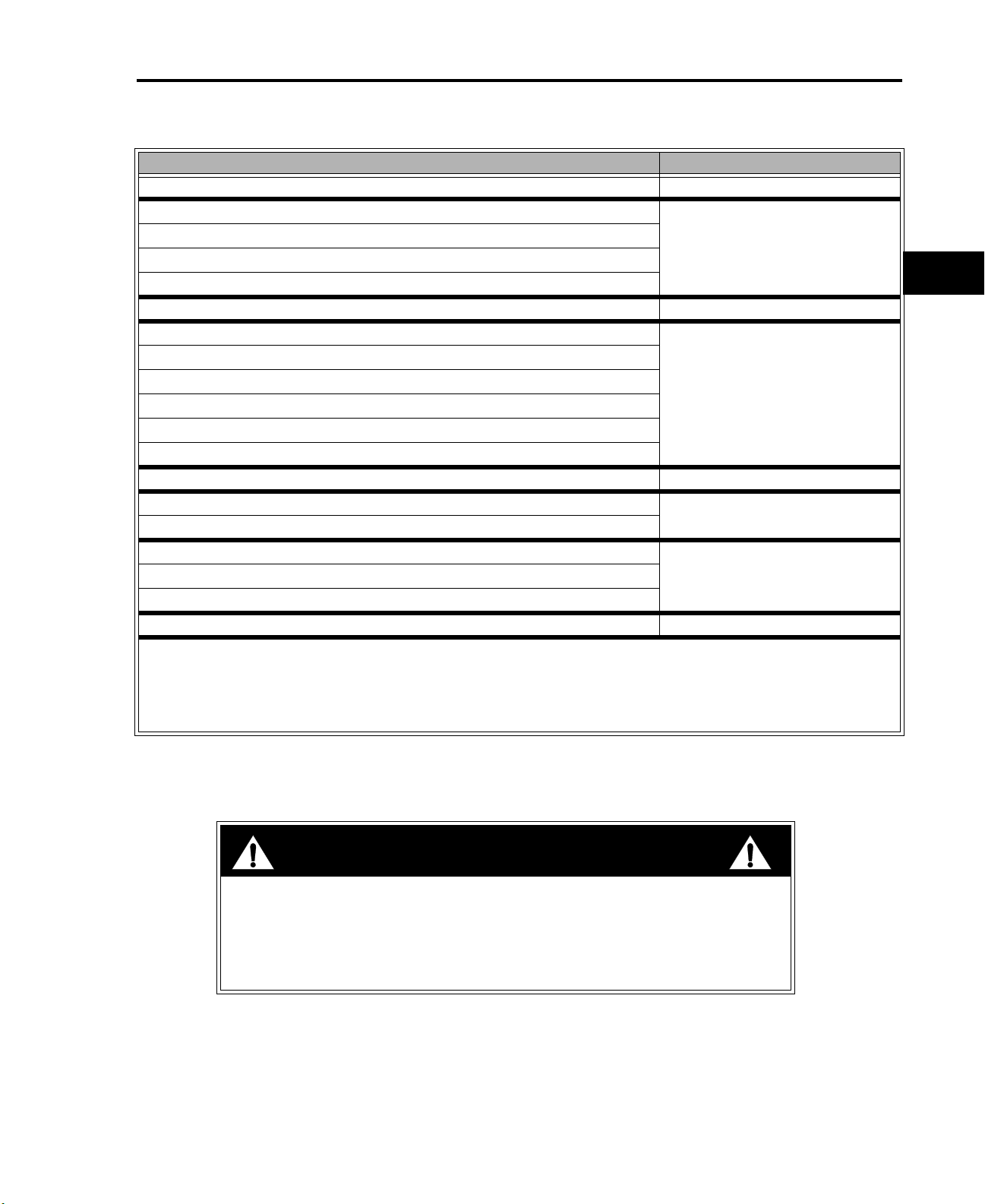
Maintenance Schedule (Z18-52)
Maintenance Procedure Service Interval
Change the engine oil After first use
Check the engine oil level
Check the safety system
Clean the air intake screen
Clean the mower housing
Check the cutting blades Every 5 hours
Grease all lubrication points
Oil the linkage bushings
Service the foam air cleaner
Check the belts for wear/cracks
Check the battery electrolyte
Check the tire pressure
Service the paper air cleaner
Change the engine oil
Check the spark plug(s)
Change the oil filter
Replace the paper air cleaner
Clean the engine shrouds and cooling fins
Before Storage:
• Perform all maintenance procedures listed above.
• Drain the fuel tank.
• Charge the battery and disconnect the battery cables.
• Paint any chipped surfaces.
1
1
1
1
1
1
Each use
Every 25 hours
Every 50 hours
Every 100 hours
Every 200 hoursReplace the fuel filter
Every 300 hours
1c
1
More often in dusty, dirty conditions
IMPORTANT: Refer to your engine operator’s manual for additional maintenance procedures.
CAUTION
If you leave the key in the ignition switch, someone could accidently start the
engine and seriously injury you or other bystanders.
Remove the key from the ignition and disconnect the wire from the spark
plug(s) before you do any maintenance. Set the wire aside so that it does not
accidentally contact the spark plug.
TimeCutter™ Z Service Manual 1 - 9
Page 24

THIS PAGE INTENTIONALLY LEFT BLANK
1 - 10 TimeCutter™ Z Service Manual
Page 25

MODEL/SERIAL NUMBER LOCATION
QUICK REFERENCE SECTION
Safety Information . . . . . . . . . . . . . . . . . . . . . . . . . . . . . . . . . . . . . . . . . . . . . . .
Specifications. . . . . . . . . . . . . . . . . . . . . . . . . . . . . . . . . . . . . . . . . . . . . . . . . . .
Maintenance . . . . . . . . . . . . . . . . . . . . . . . . . . . . . . . . . . . . . . . . . . . . . . . . . . .
SERVICE SECTION
Model/Serial Number . . . . . . . . . . . . . . . . . . . . . . . . . . . . . . . . . . . . . . . . . . . .
Greasing and Lubrication. . . . . . . . . . . . . . . . . . . . . . . . . . . . . . . . . . . . . . . . . .
Engine . . . . . . . . . . . . . . . . . . . . . . . . . . . . . . . . . . . . . . . . . . . . . . . . . . . . . . . .
Transaxle . . . . . . . . . . . . . . . . . . . . . . . . . . . . . . . . . . . . . . . . . . . . . . . . . . . . . .
1a
1b
1c
2
3
4
5
Chassis . . . . . . . . . . . . . . . . . . . . . . . . . . . . . . . . . . . . . . . . . . . . . . . . . . . . . . .
Mower Decks . . . . . . . . . . . . . . . . . . . . . . . . . . . . . . . . . . . . . . . . . . . . . . . . . . .
Electrical Systems . . . . . . . . . . . . . . . . . . . . . . . . . . . . . . . . . . . . . . . . . . . . . . .
6
7
8
TimeCutter™ Z Service Manual 2 - 1
Page 26

MODEL/SERIAL NUMBER LOCATION
Table of Contents
MODEL/SERIAL NUMBER LOCATION . . . . . . . . . . . . . . . . . . . . . . . . . . . . . . . . 2 - 3
2 - 2 TimeCutter™ Z Service Manual
Page 27

0702-0201
MODEL/SERIAL NUMBER LOCATION
MODEL/SERIAL NUMBER LOCATION
The unit model and serial number plate is on the
frame under the seat as shown in the illustration.
The engine has its own model and serial number
identification. Consult the appropriate engine
manufacturer’s service literature for the location
and translation of the engine model and serial
number information.
0702-0202
Transaxles also have their own model/serial
number.
2
TimeCutter™ Z Service Manual 2 - 3
Page 28

THIS PAGE INTENTIONALLY LEFT BLANK
2 - 4 TimeCutter™ Z Service Manual
Page 29

QUICK REFERENCE SECTION
GREASING AND LUBRICATION
Safety Information . . . . . . . . . . . . . . . . . . . . . . . . . . . . . . . . . . . . . . . . . . . . . . .
Specifications. . . . . . . . . . . . . . . . . . . . . . . . . . . . . . . . . . . . . . . . . . . . . . . . . . .
Maintenance . . . . . . . . . . . . . . . . . . . . . . . . . . . . . . . . . . . . . . . . . . . . . . . . . . .
SERVICE SECTION
Model/Serial Number . . . . . . . . . . . . . . . . . . . . . . . . . . . . . . . . . . . . . . . . . . . . .
Greasing and Lubrication . . . . . . . . . . . . . . . . . . . . . . . . . . . . . . . . . . . . . . . .
Engine . . . . . . . . . . . . . . . . . . . . . . . . . . . . . . . . . . . . . . . . . . . . . . . . . . . . . . . .
Transaxle . . . . . . . . . . . . . . . . . . . . . . . . . . . . . . . . . . . . . . . . . . . . . . . . . . . . . .
1a
1b
1c
2
3
4
5
Chassis . . . . . . . . . . . . . . . . . . . . . . . . . . . . . . . . . . . . . . . . . . . . . . . . . . . . . . .
Mower Decks . . . . . . . . . . . . . . . . . . . . . . . . . . . . . . . . . . . . . . . . . . . . . . . . . . .
Electrical Systems . . . . . . . . . . . . . . . . . . . . . . . . . . . . . . . . . . . . . . . . . . . . . . .
6
7
8
TimeCutter™ Z Service Manual 3 - 1
Page 30

GREASING AND LUBRICATION
Table of Contents
Service Interval/Specification . . . . . . . . . . . . . . . . . . . . . . . . . . . . . . . . . . . . . . . . 3 - 3
Lubrication Points . . . . . . . . . . . . . . . . . . . . . . . . . . . . . . . . . . . . . . . . . . . . . . . . . 3 - 4
3 - 2 TimeCutter™ Z Service Manual
Page 31

0702-0301
GREASING AND LUBRICATION
Service Interval/Specification
The unit should be greased every 25 hours;
more often when operating in dirty, dusty, or
sandy conditions.
A decal located under the seat shows the
location of all the grease zerks.
Grease Type: General-purpose lithium base
grease.
3
0702-0302
TimeCutter™ Z Service Manual 3 - 3
Page 32

GREASING AND LUBRICATION
Lubrication Points
There is a grease fitting on the mower for right
and left outer spindle.
0702-0303
3
The grease zerk for the center mower spindle.
0702-0304
There is a grease fitting for the deck idler arm
bushing.
0702-0305
3 - 4 TimeCutter™ Z Service Manual
Page 33

0702-0306
GREASING AND LUBRICATION
There are 2 grease fittings for the deck raising
pivot bushings - one on each side of the unit.
0702-0307
The grease zerk for the deck height adjustment
lever is on the right side of the machine.
There are grease fittings for each front castor
bushing,
3
0702-0308
TimeCutter™ Z Service Manual 3 - 5
Page 34

GREASING AND LUBRICATION
as well as the castor wheel bearings.
0702-0309
3
The zerk fitting for the traction belt idler bushing
is located under the seat.
0702-0310
Also under the seat are the fittings for the motion
control lever pivot bushings - one for each lever.
0702-0311
3 - 6 TimeCutter™ Z Service Manual
Page 35

QUICK REFERENCE SECTION
ENGINE
Safety Information . . . . . . . . . . . . . . . . . . . . . . . . . . . . . . . . . . . . . . . . . . . . . . .
Specifications. . . . . . . . . . . . . . . . . . . . . . . . . . . . . . . . . . . . . . . . . . . . . . . . . . .
Maintenance . . . . . . . . . . . . . . . . . . . . . . . . . . . . . . . . . . . . . . . . . . . . . . . . . . .
SERVICE SECTION
Model/Serial Number . . . . . . . . . . . . . . . . . . . . . . . . . . . . . . . . . . . . . . . . . . . . .
Greasing and Lubrication. . . . . . . . . . . . . . . . . . . . . . . . . . . . . . . . . . . . . . . . . .
Engine . . . . . . . . . . . . . . . . . . . . . . . . . . . . . . . . . . . . . . . . . . . . . . . . . . . . . . .
Transaxle . . . . . . . . . . . . . . . . . . . . . . . . . . . . . . . . . . . . . . . . . . . . . . . . . . . . . .
1a
1b
1c
2
3
4
5
Chassis . . . . . . . . . . . . . . . . . . . . . . . . . . . . . . . . . . . . . . . . . . . . . . . . . . . . . . .
Mower Decks . . . . . . . . . . . . . . . . . . . . . . . . . . . . . . . . . . . . . . . . . . . . . . . . . . .
Electrical Systems . . . . . . . . . . . . . . . . . . . . . . . . . . . . . . . . . . . . . . . . . . . . . . .
6
7
8
TimeCutter™ Z Service Manual 4 - 1
Page 36

ENGINE
Briggs & Stratton Engine . . . . . . . . . . . . . . . . . . . . . . . . . . . . . . . . . . . . . . . . . . . 4 - 3
Kohler Engine . . . . . . . . . . . . . . . . . . . . . . . . . . . . . . . . . . . . . . . . . . . . . . . . . . . . 4 - 3
Kawasaki Engine . . . . . . . . . . . . . . . . . . . . . . . . . . . . . . . . . . . . . . . . . . . . . . . . . 4 - 3
Briggs & Stratton Air Cleaner . . . . . . . . . . . . . . . . . . . . . . . . . . . . . . . . . . . . . . . . 4 - 4
Kohler Air Cleaner . . . . . . . . . . . . . . . . . . . . . . . . . . . . . . . . . . . . . . . . . . . . . . . . 4 - 4
Kawasaki Air Cleaner . . . . . . . . . . . . . . . . . . . . . . . . . . . . . . . . . . . . . . . . . . . . . . 4 - 4
Spark Plug . . . . . . . . . . . . . . . . . . . . . . . . . . . . . . . . . . . . . . . . . . . . . . . . . . . . . . 4 - 5
Engine Remove and Replace . . . . . . . . . . . . . . . . . . . . . . . . . . . . . . . . . . . . . . . 4 - 6
Table of Contents
4 - 2 TimeCutter™ Z Service Manual
Page 37

ENGINE
Briggs & Stratton Engine
Oil Type: Detergent oil (API service SF, SG, SH,
SJ, or higher).
0702-0401
5W-20, 5W-30
5W-30, 10W-30
SYNTHETIC 5W-20, 5W-30
SAE 30
10W-30
Crankcase Capacity (with filter): 1.75 qt. (1.7 l).
Crankcase Capacity (without filter): 1.5 qt. (1.4 l).
Viscosity: See table.
Change Oil:
• After the first use.
• Every 100 hours.
Change oil filter every 200 hours.
Kohler Engine
Oil Type: Detergent oil (API service SG, SH, SJ,
or higher).
Crankcase Capacity (with filter): 2.1 qt. (2 l).
Viscosity: See table.
Change Oil (Kohler):
• Every 50 hours.
4
0702-0402
0702-0403
USE THESE SAE VISCOSITY OILS
Change oil filter every 100 hours.
Kawasaki Engine
Oil Type: Detergent oil (API service SC, SD, SE,
SF, SG, or SH).
Crankcase Capacity (with filter): 1.6 qt. (1.5 l).
Viscosity: See table.
Change Oil (Kawasaki):
• After the first use.
• Every 100 hours.
Change oil filter every 200 hours.
TimeCutter™ Z Service Manual 4 - 3
Page 38

ENGINE
Briggs & Stratton Air Cleaner
The air cleaner assembly consists of a paper
filter element and a foam precleaner.
To clean the paper element, tap lightly on a flat
surface to remove dust and dirt. Inspect the
element for tears, oil contamination, and damage
to the rubber seal.
NOTE: Never clean the paper element with
compressed air or solvents. If the element is
dirty or damaged, replace it immediately.
(A) Paper Element
(B) Foam Precleaner
(C) Cover
Kohler Air Cleaner
The air cleaner assembly consists of a paper
filter element and a foam precleaner.
C
B
A
0702-0404
C
4
To clean the paper element, tap lightly on a flat
surface to remove dust and dirt. Inspect the
element for tears, oil contamination, and damage
to the rubber seal.
NOTE: Never clean the paper element with
compressed air or solvents. If the element is
dirty or damaged, replace it immediately.
(A) Paper Element
(B) Foam Precleaner
(C) Cover
Kawasaki Air Cleaner
The air cleaner assembly consists of a paper
filter element and a foam precleaner.
To clean the paper element, tap lightly on a flat
surface to remove dust and dirt. Inspect the
element for tears, oil contamination, and damage
to the rubber seal.
NOTE: Never clean the paper element with
compressed air or solvents. If the element is
dirty or damaged, replace it immediately.
(A) Cover
(B) Air Filter
B
A
0702-0405
A
B
0702-0406
4 - 4 TimeCutter™ Z Service Manual
Page 39

0702-0407
N
E
W
P
H
O
T
O
ENGINE
Every 25 hours (more often in dusty, dirty
conditions) wash the foam element in liquid soap
and warm water. When the element is clean,
rinse it thoroughly.
Dry the element by squeezing it in a clean cloth
(do not wring). Allow the element to air dry.
Follow engine manufacturer’s recommendation
for treatment of pre cleaner prior to installation.
Spark Plug
On Briggs & Stratton and Kawasaki engines,
replace the spark plug(s) every 100 operating
hours.
On Kohler engines, check the spark plug(s) every
200 operating hours.
If the insulator on the spark plug(s) is light brown or
gray, the engine is running properly. A black
coating on the insulator indicates the air cleaner
may be dirty.
IMPORTANT: Never clean the spark plug(s).
Always replace the spark plug(s) when it has a
black coating, worn electrodes, an oily film, or
cracks.
4
Gap (all engines): .030” (0.76 mm)
Typ e:
0144-011
TimeCutter™ Z Service Manual 4 - 5
Kohler / Briggs & Stratton:Champion RC12YC
(or equivalent)
Kawasaki: Champion RCJ86 (or equivalent)
Page 40

ENGINE
Engine Remove and Replace
Disconnect the negative battery cable.
Close the fuel shut-off.
0702-0408
N
E
W
P
H
O
T
O
4
0702-0409
Remove the fuel line from the fuel filter.
0702-0410
4 - 6 TimeCutter™ Z Service Manual
Page 41

0702-0411
ENGINE
Disconnect the clutch PTO wiring.
Disconnect the engine wiring harness plug.
0702-0412
4
Loosen the throttle/choke cable clamp and
remove the cable from the governor linkage.
0702-0413
TimeCutter™ Z Service Manual 4 - 7
Page 42

ENGINE
Remove the ground cable from the engine block.
On Kohler engines, loosen the oil filter base bolts
and remove the filter base.
0702-0414
4
0702-0415
Remove the starter cable.
0702-0416
4 - 8 TimeCutter™ Z Service Manual
Page 43

0702-0417
ENGINE
Remove mower drive belt. See complete
procedure in Chapter 8.
Remove the clutch bolt and lower the clutch
assembly.
0702-0418
4
Remove traction drive belt.
Move the idler pulley to lessen the tension on the
traction drive belt and slip the belt up off the
engine drive pulley. Then remove the clutch and
drive pulley from the crankshaft.
0702-0419
TimeCutter™ Z Service Manual 4 - 9
Page 44

ENGINE
Remove the 4 engine mounting bolts.
Lift the engine from the chassis.
0702-0420
4
Reverse the above steps to replace.
0702-0421
4 - 10 TimeCutter™ Z Service Manual
Page 45

QUICK REFERENCE SECTION
TRANSAXLE
Safety Information . . . . . . . . . . . . . . . . . . . . . . . . . . . . . . . . . . . . . . . . . . . . . . .
Specifications. . . . . . . . . . . . . . . . . . . . . . . . . . . . . . . . . . . . . . . . . . . . . . . . . . .
Maintenance . . . . . . . . . . . . . . . . . . . . . . . . . . . . . . . . . . . . . . . . . . . . . . . . . . .
SERVICE SECTION
Model/Serial Number . . . . . . . . . . . . . . . . . . . . . . . . . . . . . . . . . . . . . . . . . . . . .
Greasing and Lubrication. . . . . . . . . . . . . . . . . . . . . . . . . . . . . . . . . . . . . . . . . .
Engine . . . . . . . . . . . . . . . . . . . . . . . . . . . . . . . . . . . . . . . . . . . . . . . . . . . . . . . .
Transaxle . . . . . . . . . . . . . . . . . . . . . . . . . . . . . . . . . . . . . . . . . . . . . . . . . . . . .
1a
1b
1c
1c
2
3
4
5
Chassis . . . . . . . . . . . . . . . . . . . . . . . . . . . . . . . . . . . . . . . . . . . . . . . . . . . . . . .
Mower Decks . . . . . . . . . . . . . . . . . . . . . . . . . . . . . . . . . . . . . . . . . . . . . . . . . . .
Electrical Systems . . . . . . . . . . . . . . . . . . . . . . . . . . . . . . . . . . . . . . . . . . . . . . .
6
7
8
TimeCutter™ Z Service Manual 5 - 1
Page 46

TRANSAXLE
Troubleshooting Checklist . . . . . . . . . . . . . . . . . . . . . . . . . . . . . . . . . . . . . . . . . . 5 - 3
Fluids . . . . . . . . . . . . . . . . . . . . . . . . . . . . . . . . . . . . . . . . . . . . . . . . . . . . . . . . . . 5 - 4
Remove and Replace Transaxle . . . . . . . . . . . . . . . . . . . . . . . . . . . . . . . . . . . . . 5 - 5
Reassembly . . . . . . . . . . . . . . . . . . . . . . . . . . . . . . . . . . . . . . . . . . . . . . . . . . . . 5 - 10
Control Handle-Return To Neutral Adjustment . . . . . . . . . . . . . . . . . . . . . . . . . . 5 - 14
Purging the System . . . . . . . . . . . . . . . . . . . . . . . . . . . . . . . . . . . . . . . . . . . . . . 5 - 16
Neutral Adjustment . . . . . . . . . . . . . . . . . . . . . . . . . . . . . . . . . . . . . . . . . . . . . . . 5 - 18
Tracking Adjustment . . . . . . . . . . . . . . . . . . . . . . . . . . . . . . . . . . . . . . . . . . . . . 5 - 22
Table of Contents
Control Handle Adjustment . . . . . . . . . . . . . . . . . . . . . . . . . . . . . . . . . . . . . . . . 5 - 24
5 - 2 TimeCutter™ Z Service Manual
Page 47

TROUBLESHOOTING CHECKLIST
Possible Cause Corrective Action
UNIT OPERATES IN ONE DIRECTION ONLY
TRANSAXLE
Control linkage bent or out of adjustment.
Drive belt slipping or pulley damaged.
VEHICLE DOES NOT DRIVE/TRACK STRAIGHT
Vehicle tires improperly inflated.
Control linkage bent, loose, or out of adjustment.
Bypass partially engaged.
Oil level low or contaminated oil.
Excessive loading.
Brake setting incorrect.
Loose parts.
Bypass assembly sticking.
Air trapped in hydraulic system.
UNIT HAS NO/LOW POWER
Engine speed low.
Control linkage bent or out of adjustment.
Brake setting incorrect.
Drive belt slipping or pulley damaged.
Oil level low or contaminated oil.
Excessive loading.
Bypass assembly sticking.
Air trapped in hydraulic system.
Repair or replace linkage.
Repair or replace drive belt or pulley.
Inflate to recommended pressure. Check tire
diameters are approximately equal, side-to-side.
Repair, adjust, or replace vehicle linkage.
Adjust bypass linkage.
UNIT IS NOISY
Fill to proper level or change oil.
Reduce vehicle loading.
Adjust brake to proper setting.
Repair or replace loose parts.
Repair or replace valve or linkage.
Purge hydraulic system.
Adjust to correct setting.
Repair or replace linkage.
Adjust brake to proper setting.
Repair or replace drive belt or pulley.
Fill to proper level or change oil.
Reduce vehicle loading.
Repair or replace valve or linkage.
Purge hydraulic system.
5
UNIT OPERATING HOT
Debris buildup around transaxle.
Brake setting incorrect.
Cooling fan damaged.
Oil level low or contaminated oil.
Excessive loading.
Air trapped in hydraulic system.
TRANSAXLE LEAKS OIL
Damaged seals, housing, or gaskets.
Air trapped in hydraulic system.
TimeCutter™ Z Service Manual 5 - 3
Clean off debris.
Adjust brake to proper setting.
Repair or replace cooling fan.
Fill to proper level or change oil.
Reduce vehicle loading.
Purge hydraulic system.
Replace damaged component.
Purge hydraulic system.
Page 48

TRANSAXLE
Fluids
Engine oil with a minimum rating of 55 SUS at
212 F° and an API classification of SH/CD is
recommended. A 20W-50 engine oil has been
selected for use by the factory and is
recommended for normal operating
temperatures.
Check oil level when cold. To check the
transaxle fluid level, remove the vent. Oil level
should be 1-7/8” - 2-3/16” (4.8 cm - 5.56 cm)
from the top of the vent port.
0702-0501
5
The oil level can only be checked when the
transaxle is removed from the machine.
0702-0502
5 - 4 TimeCutter™ Z Service Manual
Page 49

0702-0408
TRANSAXLE
Remove and Replace Transaxle
Disconnect the battery.
Close the fuel shut-off.
0702-0409
5
Raise the rear of the unit and support it with jack
stands.
0702-0505
TimeCutter™ Z Service Manual 5 - 5
Page 50

TRANSAXLE
Remove the clip that secures the vent hose to
the chassis.
If necessary, engage the parking brake to
facilitate wheel removal.
0702-0506
5
0702-0507
Remove the wheel assembly.
0702-0508
5 - 6 TimeCutter™ Z Service Manual
Page 51

0702-0509
TRANSAXLE
Remove the parking brake link from the brake
arm.
Disconnect the motion control link from the
transaxle.
0702-0510
5
Remove the hairpin cotter and washer from the
bypass valve lever. Leave the rod in place.
0702-0511
TimeCutter™ Z Service Manual 5 - 7
Page 52

TRANSAXLE
Move the idler pulley to lessen the tension on the
traction drive belt and slip the belt up off the
engine drive pulley.
Remove the belt from the transaxle being
removed.
0702-0419
5
0702-0512
Loosen and remove the 6 bolts and washer
between both transaxles. Remove the hydro
lower plate. Note the orientation of the hydro
lower plate. It must be reinstalled with the lip
facing down, toward the front.
0702-0513
5 - 8 TimeCutter™ Z Service Manual
Page 53

0702-0514
TRANSAXLE
Support the transaxle with a jack while removing
the last bolts.
Guide the transaxle as it is lowered. Make sure
the cooling fan and vent hose clear the chassis.
0702-0515
5
TimeCutter™ Z Service Manual 5 - 9
Page 54

TRANSAXLE
Reassembly
IMPORTANT: Before installing a new transaxle,
check
the oil level and check the torque on the
nut retaining the input pulley. Torque to 30 - 35
ft. lbs. (40.7 N·m - 47.5 N·m).
Use a jack to lift the transaxle into the chassis.
Carefully guide it into position so that the cooling
fan does not catch on the chassis and the
bypass rod is properly positioned in the lever.
Insert the vent hose through the slot provided for
it in the frame.
0702-0516
5
Install the two axle bolts, washer, and nuts to the
frame. Do not tighten the bolts. Reinstall the
rest of the bolts, washers, and nuts in the lower
hydro plate. If the plate was completely
removed, make sure the lip of the plate is
pointing to the front and down. Tighten the
transaxle bolts and nuts following the sequence
shown in the photo. Torque the bolts and nuts to
200 in. lbs. (22.6 N·m)
0702-0515
5
2
3
1
4
0702-0513
5 - 10 TimeCutter™ Z Service Manual
Page 55

1s-0802
TRANSAXLE
Place the traction belt on the pulley. Check for
correct belt routing.
(A) Engine Pulley
(B) Idler Pulley
(C) Right Hydro
(D) Left Hydro
Install the hairpin cotter pin and washer on the
bypass valve lever.
0702-0511
5
Reinstall the motion control link.
0702-0517
TimeCutter™ Z Service Manual 5 - 11
Page 56

TRANSAXLE
NOTE: The length of the link is set at the factory
and should not normally require adjustment in
the field.
If the link has been tampered with, the distance
between bolt centers is:
• Left side 3.6” (9.14 cm)
• Right side 3.1” (7.9 cm)
Install the parking brake linkage.
0702-0517
5
0702-0509
Replace the wheel assembly.
0702-0508
5 - 12 TimeCutter™ Z Service Manual
Page 57

0702-0506
TRANSAXLE
Secure the vent hose to the chassis.
Recheck to make sure the brake arm clears the
teeth of the brake cog when the park brake is
disengaged.
0702-0518
5
TimeCutter™ Z Service Manual 5 - 13
Page 58

TRANSAXLE
Control Handle-Return To Neutral Adjustment
1. With the engine off, move the directional
control handles to the reverse position.
2. Let the handles go. They should return to
the neutral position, which means the handle
should line up with the neutral slot (neutral
lockout position).
0702-0519
5
0702-0520
3. If adjustment is needed:
A. Lift the seat and located the adjusters.
Loosen the jam nut on the yoke.
0702-0521
5 - 14 TimeCutter™ Z Service Manual
Page 59

0702-0522
TRANSAXLE
B. Turn the top bolt head until the
directional control handle is lined up with
the neutral slot (Neutral Lockout
Position).
C. Tighten the jam nut and then test the
directional control handle by pulling the
handle in reverse and then let the handle
go. It should return to the neutral slot.
0702-0520
D. Before starting the unit, follow the
procedures on Purging the System.
5
TimeCutter™ Z Service Manual 5 - 15
Page 60

TRANSAXLE
Purging the System
Due to the effects air has on efficiency in
hydrostatic drive applications, it is critical that it
be purged from the system.
These purge procedures should be implemented
any time a hydrostatic system has been opened
to facilitate maintenance or any additional oil has
been added to the system.
Air creates inefficiency because its compression
and expansion rate is higher than that of the oil
normally approved for use in hydrostatic drive
systems.
0702-0516
5
2001-027
The following procedures should be performed
with the vehicle drive wheels off the ground, the
seat switch temporarily bypassed, and the brake
arm completely disengaged from the brake cog,
(see Parking Brake Adjustment page 6 - 18).
The procedure may need to be repeated under
normal operating conditions.
1. With the bypass valves open (hand push
mode) and the engine running, slowly move
the directional control handles in both
forward and reverse directions 5 to 6 times,
to purge trapped air from the unit.
0702-0523
5 - 16 TimeCutter™ Z Service Manual
Page 61

0702-0524
TRANSAXLE
2. Place the bypass valves in the closed
position (operating). With the engine
running, slowly move the directional control
handles through the forward and reverse
directions (5 to 6 times).
3. It may be necessary to repeat steps 1 and 2
until all the air is completely purged from the
system. When the transaxle moves forward
and reverse at normal speed, purging is
complete.
5
TimeCutter™ Z Service Manual 5 - 17
Page 62

TRANSAXLE
Neutral Adjustment
1. If the unit creeps in neutral, it will be
necessary to make an adjustment to the
transaxle.
2. Operate the unit to determine which
transaxle needs adjustment.
3. Raise the unit and place it on jack stands.
0702-0525
5
4. Warm the transaxle fluid by running for at
least 10 minutes.
0702-0505
5. Unplug the seat switch and temporarily
connect a jumper wire across the plug
connector.
2001-050
5 - 18 TimeCutter™ Z Service Manual
Page 63

0702-0526
TRANSAXLE
6. Place the directional control handles in the
neutral lockout position. Start the engine
and run at half throttle.
7. The rear traction wheels should remain
stationary or creep slightly in reverse.
0702-0527
5
8. If necessary, loosen the jam nuts (A) and
turn the control rod until the wheel stops
between forward and reverse. In some
cases, you may have a slight creep in
reverse. When you lower the unit to the
ground, it should stop.
A
0702-05028
TimeCutter™ Z Service Manual 5 - 19
Page 64

TRANSAXLE
9. After you have adjusted the rods, move the
directional control handle in reverse position,
then let go of the handles. The handles
should move to the neutral position and the
drive wheels should remain stationary, or
have a very slight amount of creep in
reverse. The wheels should not creep in the
forward direction when the control handles
are in the neutral lock out position.
10. Run the engine at full throttle. Check neutral
again by moving the directional control
handles in reverse, then let go of the
handles. The handles should move to the
neutral position and the drive wheels should
not move. A slight creep could be observed
when the machine is elevated. However,
when lowering the unit to the ground, the
5
weight of the unit should stop the creep.
0702-0529
0702-0530
11. When the adjustment is complete, hold the
control rod stationary with pliers and tighten
the jam nuts. Always test again to make
sure the unit is still neutralized.
0702-0531
5 - 20 TimeCutter™ Z Service Manual
Page 65

0702-0532
TRANSAXLE
12. Remove the jumper wire on the seat switch
and plug the switch into the harness. Lower
the unit to the ground.
5
TimeCutter™ Z Service Manual 5 - 21
Page 66

TRANSAXLE
Tracking Adjustment
When operating the unit in forward, it is not
unusual for the unit to track slightly right or left
when going for a distance. This is because of
the different tolerances between two different
hydrostatic pumps. If the tracking deviation is
large, check the following.
NOTE: Ground surface should be level when
checking the tracking.
1. Check the tire pressure in each tire. 13 psi
(90 kPa) rear, 35 psi (241 kPa) front. Tire
pressure has a great influence on the
tracking of these units.
0702-0525
5
It is advisable to check for a large deviation
in outside diameter of the tires, side-to-side,
if the tracking error is severe. Also, check
that the front casters rotate freely, and the
front wheel bearings are in good condition.
0702-0533
2. You may be able to make a slight tracking
adjustment by turning the neutral control
rods without affecting the neutral position.
IMPORTANT: Be sure to recheck the
neutral adjustment to be sure the machine
does not creep after correcting the tracking.
0702-0528
5 - 22 TimeCutter™ Z Service Manual
Page 67

0702-0527
TRANSAXLE
NOTE: All of the control linkage is set up for
forward motion. It is not unusual to have a large
tracking error when going a distance in reverse.
Do not try to adjust reverse tracking. If you do, it
will misadjust the forward linkage.
3. After attempting any tracking change with
the unit, make sure it is still neutralized.
5
TimeCutter™ Z Service Manual 5 - 23
Page 68

TRANSAXLE
Control Handle Adjustment
If the directional control handles do not line up
with each other, they require adjustment.
1. Loosen the bolts attaching the handles to the
control linkage.
2. Adjust the position of the handles so that
they are aligned. Tighten the bolts after
adjustment.
0702-0534
5
0702-0535
5 - 24 TimeCutter™ Z Service Manual
Page 69

PICT-6171
TRANSAXLE
Transaxle Identifi cation Model Year 2001 - 2004
Hydro-Gear Model 310-2400 IZT Transaxles
Transaxle Identifi cation Model Year 2005 and Later
Hydro-Gear Model 310-2600 IZT with a Charge Pump
MVC-353X
5
A5-25TimeCutter ZX Service Manual
Page 70

TRANSAXLE
THIS PAGE INTENTIONALLY LEFT BLANK.
5
A5-26 TimeCutter ZX Service Manual
Page 71

QUICK REFERENCE SECTION
CHASSIS
Safety Information . . . . . . . . . . . . . . . . . . . . . . . . . . . . . . . . . . . . . . . . . . . . . . .
Specifications. . . . . . . . . . . . . . . . . . . . . . . . . . . . . . . . . . . . . . . . . . . . . . . . . . .
Maintenance . . . . . . . . . . . . . . . . . . . . . . . . . . . . . . . . . . . . . . . . . . . . . . . . . . .
SERVICE SECTION
Model/Serial Number . . . . . . . . . . . . . . . . . . . . . . . . . . . . . . . . . . . . . . . . . . . . .
Greasing and Lubrication. . . . . . . . . . . . . . . . . . . . . . . . . . . . . . . . . . . . . . . . . .
Engine . . . . . . . . . . . . . . . . . . . . . . . . . . . . . . . . . . . . . . . . . . . . . . . . . . . . . . . .
Transaxle . . . . . . . . . . . . . . . . . . . . . . . . . . . . . . . . . . . . . . . . . . . . . . . . . . . . . .
1a
1b
1c
2
3
4
5
Chassis. . . . . . . . . . . . . . . . . . . . . . . . . . . . . . . . . . . . . . . . . . . . . . . . . . . . . . .
Mower Decks . . . . . . . . . . . . . . . . . . . . . . . . . . . . . . . . . . . . . . . . . . . . . . . . . . .
Electrical Systems . . . . . . . . . . . . . . . . . . . . . . . . . . . . . . . . . . . . . . . . . . . . . . .
6
7
8
TimeCutter™ Z Service Manual 6 - 1
Page 72

CHASSIS
Table of Contents
Remove and Replace Dampers . . . . . . . . . . . . . . . . . . . . . . . . . . . . . . . . . . . . . 6 - 3
Remove and Replace Control Linkage . . . . . . . . . . . . . . . . . . . . . . . . . . . . . . . . 6 - 4
Replace Control Linkage . . . . . . . . . . . . . . . . . . . . . . . . . . . . . . . . . . . . . . . . . . . 6 - 8
Remove and Replace Brake Linkage . . . . . . . . . . . . . . . . . . . . . . . . . . . . . . . . .6 - 11
Replace Brake Linkage . . . . . . . . . . . . . . . . . . . . . . . . . . . . . . . . . . . . . . . . . . . 6 - 15
Parking Brake Adjustment . . . . . . . . . . . . . . . . . . . . . . . . . . . . . . . . . . . . . . . . . 6 - 18
Replace Traction Belt . . . . . . . . . . . . . . . . . . . . . . . . . . . . . . . . . . . . . . . . . . . . 6 - 20
TimeCutter™ Z Service Manual 6 - 2
Page 73

0702-0601
CHASSIS
Remove and Replace Dampers
Remove the E-clip and washer at the bottom of
the damper.
Remove the bolt at the top of the damper and
remove the damper.
0702-0602
6
TimeCutter™ Z Service Manual 6 - 3
Page 74

CHASSIS
Remove and Replace Control Linkage
Remove the control arm.
Remove the electrical connector from the motion
control switch.
0702-0603
6
Remove the pin from the return to neutral yoke.
N
0702-0604
E
W
P
H
O
T
O
0702-0605
6 - 4 TimeCutter™ Z Service Manual
Page 75

0702-0606
CHASSIS
Remove the link between the front and rear
bellcranks.
NOTE: All the ball joint assemblies are installed
with a flat washer between the ball joint and
lever.
0702-0607
0702-0608
6
Disconnect the steering damper.
TimeCutter™ Z Service Manual 6 - 5
Page 76

CHASSIS
Remove the bolts securing the bushings at each
end of the control shaft.
Remove the control shaft.
0702-0609
6
0702-0610
Disconnect the link between the transaxle and
the bellcrank.
NOTE: Do not change the length of the link.
0702-0611
6 - 6 TimeCutter™ Z Service Manual
Page 77

0702-0612
CHASSIS
Use a small punch to drive the roll pin out of the
upper bellcrank lever, then remove the lever and
thrust washer.
Pull the lower lever and shaft from the bushing.
0702-0613
6
TimeCutter™ Z Service Manual 6 - 7
Page 78

CHASSIS
Replace Control Linkage
Lubricate the bellcrank shaft and install in
bushing. The lever welded to the shaft goes on
the underside of the chassis.
Carefully position the top lever on the shaft and
secure with roll pin.
0702-0613
6
0702-0614
Install the link between the transaxle and
bellcrank lever.
0702-0517
6 - 8 TimeCutter™ Z Service Manual
Page 79

0702-0609
CHASSIS
Place the motion control shaft in position in the
console and secure with nuts and bolts.
NOTE: Make sure shaft is rotating freely after
installation.
Reconnect the steering damper.
0702-0608
0702-0606
6
Replace the link connecting the control shaft and
bellcrank.
TimeCutter™ Z Service Manual 6 - 9
Page 80

CHASSIS
Attach the return to neutral adjustment yoke to
the control shaft lever.
Connect the wiring to the neutral switch.
0702-0605
6
0702-0604
Position the motion control handle and secure
with 2 bolts.
0702-0603
6 - 10 TimeCutter™ Z Service Manual
Page 81

0702-0509
CHASSIS
Remove and Replace Brake Linkage
Remove the brake link from the brake arm.
Remove the clip and yoke from the brake shaft
lever.
0702-0615
0702-0616
6
Remove the cotter pin and washer from the
actuator rod.
NOTE: The actuator rod cannot be removed
from the lever at this time.
TimeCutter™ Z Service Manual 6 - 11
Page 82

CHASSIS
Remove the two clamps securing the brake
shaft.
NOTE: During reassembly, the wiring harness is
routed below the brake shaft, throttle cable is
routed above.
Remove the brake shaft from the chassis and
actuator rod.
0702-0617
6
0702-0618
To remove the front brake shaft, first remove the
brake handle.
0702-0619
6 - 12 TimeCutter™ Z Service Manual
Page 83

0702-0620
CHASSIS
Remove the brake switch.
Remove the cotter pin and washer from the
brake rod, and remove the rod.
0702-0621
0702-0622
6
Remove the two bolts and nuts securing the
bushing.
TimeCutter™ Z Service Manual 6 - 13
Page 84

CHASSIS
Remove the E-clip from the brake shaft.
To remove the bellcrank, first slide it to the
(operator’s) left then down.
0702-0623
6
0702-0624
6 - 14 TimeCutter™ Z Service Manual
Page 85

0702-0625
CHASSIS
Replace Brake Linkage
Place bearings, E Ring, and washer on the
forward brake shaft.
Position the brake shaft in the console. Secure
with nuts and bolts. Install bolts from the outside.
0702-0626
NOTE: Make sure shaft rotates freely after
installation.
6
Connect the brake rod to the brake shaft lever.
Secure with the cotter pin and washer.
0702-0621
TimeCutter™ Z Service Manual 6 - 15
Page 86

CHASSIS
Replace the brake switch and install wiring.
Install the brake handle on the brake shaft.
0702-0620
6
0702-0619
Position the rear brake shaft on the chassis with
the upper brake rod through the hole in the lever
and secure with a washer and cotter pin.
0702-0616
6 - 16 TimeCutter™ Z Service Manual
Page 87

0702-0617
CHASSIS
Make sure that the wiring harness is routed
below the brake shaft and the throttle cable
above. Then secure the brake shaft with the two
clamps.
Install the brake links to the brake arms with a
washer and cotter pin.
0702-0509
0702-0615
6
Install the adjustment yokes to the brake shaft
levers with clevis pins and hairpins.
TimeCutter™ Z Service Manual 6 - 17
Page 88

CHASSIS
Parking Brake Adjustment
The TimeCutter Z is equipped with a cog type
parking brake. When the lever is moved to the
“on” position, the brake linkage pivots the brake
arm engaging the parking brake cog and locking
the brake shaft.
IMPORTANT: Never attempt to engage the
parking brake when the unit is moving.
When the park brake is disengaged, there
must be clearance between the brake arm
and the brake cog, or severe damage could
occur to the transaxle.
(A) Brake Linkage
(B) Brake Cog
(C) Brake Arm
When the parking brake is released, the brake
arm pivots away from the brake cog allowing the
brake shaft to turn.
A
B
C
0702-0627
6
0702-0518
The brake arm is held in place by spring tension.
The nut at the bottom of the spring should have
approximately two threads showing.
NOTE: Do not attempt to adjust the parking
brake by turning this nut.
0702-0628
6 - 18 TimeCutter™ Z Service Manual
Page 89

0702-0629
CHASSIS
To adjust the parking brake:
1. Loosen the jam nut at the clevis yoke.
2. Remove the clevis pin and turn the yoke to
adjust the length of the rod until the brake
arm engages and disengages the cog
completely.
0702-0630
0702-0518
6
3. Reconnect the brake rod clevis and tighten
the jam nut. Recheck to make sure the
brake arm clears the teeth of the brake cog
when the park brake is disengaged.
TimeCutter™ Z Service Manual 6 - 19
Page 90

CHASSIS
Replace Traction Belt
Disconnect the electrical connection for the PTO
clutch.
Remove the mower deck drive belt from the left
side pulley and clutch pulley.
0702-0411
6
Place the rear of the unit on jack stands.
0702-0417
Remove the PTO clutch bolt and the electric
clutch assembly.
0702-0631
6 - 20 TimeCutter™ Z Service Manual
Page 91

0702-0632
CHASSIS
Remove traction drive belt.
Move the idler pulley to lessen the tension on the
traction drive belt and slip the belt up off the
engine drive pulley.
Remove the traction belt from the transaxle
pulleys.
0702-0512
1S-0802
6
Install the traction belt following the belt routing.
Reconnect the idler bracket spring and tighten
the eye bolt.
(A) Engine Pulley
(B) Idler Pulley
(C) Right Hydro
(D) Left Hydro
TimeCutter™ Z Service Manual 6 - 21
Page 92

CHASSIS
Reinstall the electric PTO clutch; apply Loctite
271 to the bolt.
Torque the clutch bolt to 50 - 60 ft. lbs. (68.3 -
81.8 N·m).
It will be necessary to remove the flywheel
screen and hold the flywheel nut to achieve
proper torque.
0702-0633
6
0702-0634
6 - 22 TimeCutter™ Z Service Manual
Page 93

QUICK REFERENCE SECTION
MOWER DECKS
Safety Information . . . . . . . . . . . . . . . . . . . . . . . . . . . . . . . . . . . . . . . . . . . . . . .
Specifications. . . . . . . . . . . . . . . . . . . . . . . . . . . . . . . . . . . . . . . . . . . . . . . . . . .
Maintenance . . . . . . . . . . . . . . . . . . . . . . . . . . . . . . . . . . . . . . . . . . . . . . . . . . .
SERVICE SECTION
Model/Serial Number . . . . . . . . . . . . . . . . . . . . . . . . . . . . . . . . . . . . . . . . . . . . .
Greasing and Lubrication. . . . . . . . . . . . . . . . . . . . . . . . . . . . . . . . . . . . . . . . . .
Engine . . . . . . . . . . . . . . . . . . . . . . . . . . . . . . . . . . . . . . . . . . . . . . . . . . . . . . . .
Transaxle . . . . . . . . . . . . . . . . . . . . . . . . . . . . . . . . . . . . . . . . . . . . . . . . . . . . . .
1a
1b
1c
2
3
4
5
Chassis . . . . . . . . . . . . . . . . . . . . . . . . . . . . . . . . . . . . . . . . . . . . . . . . . . . . . . .
Mower Decks . . . . . . . . . . . . . . . . . . . . . . . . . . . . . . . . . . . . . . . . . . . . . . . . . .
Electrical Systems . . . . . . . . . . . . . . . . . . . . . . . . . . . . . . . . . . . . . . . . . . . . . . .
6
7
8
TimeCutter™ Z Service Manual 7 - 1
Page 94

MOWER DECKS
44”, 48" AND 52” DECK ASSEMBLIES
Belt Removal and Replacement . . . . . . . . . . . . . . . . . . . . . . . . . . . . . . . . . . . 7 - 3
Mower Deck Remove and Replace . . . . . . . . . . . . . . . . . . . . . . . . . . . . . . . . 7 - 5
Mower Deck Side to Side Adjustment . . . . . . . . . . . . . . . . . . . . . . . . . . . . . . 7 - 8
Mower Deck Front to Rear Adjustment . . . . . . . . . . . . . . . . . . . . . . . . . . . . . . 7 - 9
Spindle Bearing Replacement . . . . . . . . . . . . . . . . . . . . . . . . . . . . . . . . . . . 7 - 11
Table of Contents
7 - 2 TimeCutter™ Z Service Manual
Page 95

0702-0701
MOWER DECKS
44”, 48" & 52” DECK ASSEMBLIES
Belt Removal and Replacement
Place the deck height lever in its lowest position.
Remove the pulley covers.
0702-0702
Remove the hairpin and washers on left and rear
mower (pork chop) bracket.
0702-0703
TimeCutter™ Z Service Manual 7 - 3
7
Page 96

MOWER DECKS
Place a length of 3/4” pipe over the idler pulley
rod and remove the belt tension. Remove the
belt from the pulley.
Reverse the steps above to reassemble. Route
the drive belt as shown.
0702-0417
7
0702-0716
7 - 4 TimeCutter™ Z Service Manual
Page 97

0702-0701
MOWER DECKS
Mower Deck Remove and Replace
Place the mower deck in its lowest position.
Remove the pulley covers.
0702-0702
Remove the belt as described in this section.
0702-0417
TimeCutter™ Z Service Manual 7 - 5
7
Page 98

MOWER DECKS
Remove the mower (pork chop) brackets.
Remove the rear trunion rods.
0702-0704
7
0702-0705
Remove the front trunion rods.
0702-0706
7 - 6 TimeCutter™ Z Service Manual
Page 99

0702-0707
MOWER DECKS
Tie the rear trunion rods to the frame.
Slide the deck out from under the right side of the
unit.
0702-0708
TimeCutter™ Z Service Manual 7 - 7
7
Page 100

MOWER DECKS
Mower Deck Side to Side Adjustment
Place the unit on a level surface. Check and
adjust the tire pressure, if necessary.
Raise the deck to the 3" (7.6 cm) position. Use a
blade height gauge to measure the distance
between the blade tips and the surface on both
sides of the deck.
If the difference is greater than 3/16”
(4.72 mm), adjustment is required.
0702-0725
7
1. Remove the spring clip and washers from
the pork chop bracket.
2. Rotate the bracket toward the front to lower,
or toward the rear to raise that side of the
deck.
3. Replace the spring clip.
NOTE: Each adjustment hole changes the
dimension by 1/8 inch.
0702-0703
7 - 8 TimeCutter™ Z Service Manual
 Loading...