

Page 1
FormNo.3363-798RevC
TimeCutter™Z5035Riding
Mower
ModelNo.74398—SerialNo.310000001andUp
ToregisteryourproductordownloadanOperator'sManualorPartsCatalogatnocharge,gotowww.T oro.com.OriginalInstructions(EN)
Page 2
Thismachineisaride-on,rotary-bladelawnmower
intendedtobeusedbyhomeownersinresidential
applications.Itisprimarilydesignedforcuttinggrass
onwell-maintainedlawns.Itisnotdesignedforcutting
brush,mowinggrassandothergrowthalongside
highways,orforagriculturaluses.
ThisproductcomplieswithallrelevantEuropean
directives,fordetailspleaseseetheseparateproduct
specicDeclarationofConformity(DOC)sheet.
Introduction
ModelNo.
SerialNo.
Thismanualidentiespotentialhazardsandhas
safetymessagesidentiedbythesafetyalertsymbol
(Figure2),whichsignalsahazardthatmaycauseserious
injuryordeathifyoudonotfollowtherecommended
precautions.
Readthisinformationcarefullytolearnhowtooperate
andmaintainyourproductproperlyandtoavoidinjury
andproductdamage.Youareresponsibleforoperating
theproductproperlyandsafely.
YoumaycontactTorodirectlyatwww .T oro.comfor
productandaccessoryinformation,helpndinga
dealer,ortoregisteryourproduct.
Wheneveryouneedservice,genuineToroparts,or
additionalinformation,contactanAuthorizedService
DealerorToroCustomerServiceandhavethemodel
andserialnumbersofyourproductready .
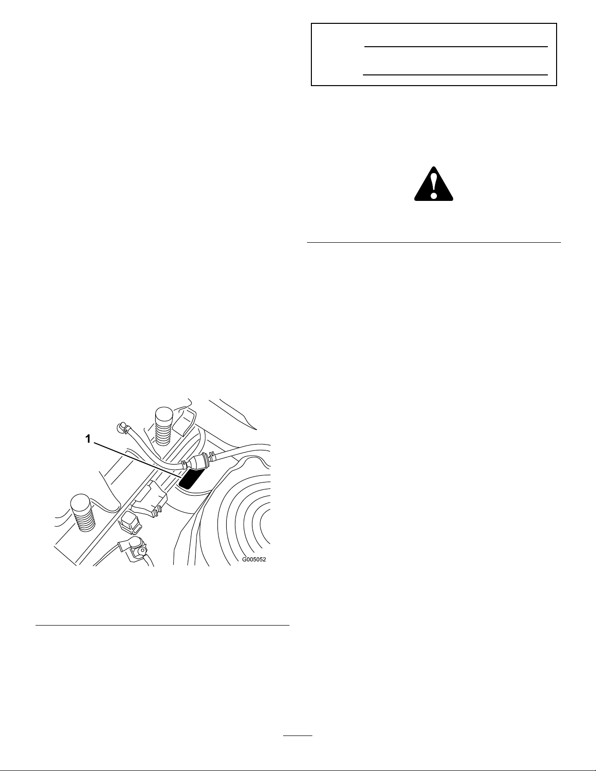
Figure1
identiesthelocationofthemodelandserialnumbers
ontheproduct.Writethenumbersinthespace
provided.
Figure1
Undertheseat
1.Modelandserialnumberplate
Writetheproductmodelandserialnumbersinthespace
below:
Figure2
1.Safetyalertsymbol.
Thismanualusestwootherwordstohighlight
information.Importantcallsattentiontospecial
mechanicalinformationandNoteemphasizesgeneral
informationworthyofspecialattention.
Contents
Introduction.................................................................2
Safety...........................................................................3
SafeOperationPracticesforRide-on(riding)
RotaryLawnmowerMachines...........................3
SafeOperatingPractices.......................................3
ToroRidingMowerSafety....................................5
Model74398........................................................5
SlopeIndicator.....................................................7
SafetyandInstructionalDecals.............................8
ProductOverview......................................................11
Controls.............................................................12
Operation...................................................................13
ThinkSafetyFirst...............................................13
RecommendedGasoline.....................................13
CheckingtheEngineOilLevel............................15
StartingandStoppingtheEngine........................15
OperatingtheBlades..........................................16
StoppingtheEngine...........................................17
TheSafetyInterlockSystem................................17
DrivingForwardorBackward.............................18
StoppingtheMachine.........................................19
AdjustingtheHeightofCut................................19
UsingtheFootAssistPedal.................................19
PositioningtheSeat............................................20
AdjustingtheMotionControlLevers..................20
PushingtheMachinebyHand.............................20
GrassDeector..................................................21
ConvertingtoSideDischarge..............................21
©2010—TheT oro®Company
8111LyndaleAvenueSouth
Bloomington,MN55420
Contactusatwww.T oro.com.
2
PrintedintheUSA.
AllRightsReserved
Page 3

OperatingTips...................................................22
Maintenance...............................................................24
RecommendedMaintenanceSchedule(s)................24
PremaintenanceProcedures....................................25
RaisingtheSeat..................................................25
AccessingtheBattery.........................................25
Lubrication.............................................................25
GreasingtheBearings.........................................25
EngineMaintenance...............................................26
ServicingtheAirCleaner....................................26
ServicingtheEngineOil.....................................27
ServicingtheSparkPlug.....................................29
CleaningtheCoolingSystem...............................30
FuelSystemMaintenance.......................................30
ReplacingtheFuelFilter.....................................30
ElectricalSystemMaintenance................................31
ChargingtheBattery...........................................31
ServicingtheFuses.............................................32
DriveSystemMaintenance.....................................33
CheckingtheTirePressure.................................33
MowerMaintenance...............................................33
ServicingtheCuttingBlades...............................33
LevelingtheMowerDeck...................................36
RemovingtheMower.........................................37
MowerBeltMaintenance....................................38
InstallingtheMower...........................................38
ReplacingtheGrassDeector.............................38
Cleaning.................................................................39
WashingtheUndersideoftheMower..................39
Storage.......................................................................40
CleaningandStorage..........................................40
Troubleshooting.........................................................42
Schematics.................................................................44
Safety
SafeOperationPractices
forRide-on(riding)Rotary
LawnmowerMachines
ThismachinemeetsorexceedsEuropeanStandardsin
effectatthetimeofproduction.However,improper
useormaintenancebytheoperatororownercan
resultininjury.Toreducethepotentialforinjury,
complywiththesesafetyinstructionsandalwayspay
attentiontothesafetyalertsymbol,whichmeans
CAUTION,W ARNING,orDANGER-“personal
safetyinstruction.”Failuretocomplywiththe
instructionmayresultinpersonalinjuryordeath.
SafeOperatingPractices
ThefollowinginstructionsarefromtheENstandard
EN836:1997.
Thisproductiscapableofamputatinghandsand
feetandthrowingobjects.Alwaysfollowallsafety
instructionstoavoidseriousinjuryordeath.
Training
•Readtheinstructionscarefully.Befamiliarwiththe
controlsandtheproperuseoftheequipment.
•Neverallowchildrenorpeopleunfamiliarwiththese
instructionstousethelawnmower.Localregulations
canrestricttheageoftheoperator.
•Nevermowwhilepeople,especiallychildren,orpets
arenearby .
•Keepinmindthattheoperatororuserisresponsible
foraccidentsorhazardsoccurringtootherpeopleor
theirproperty.
•Donotcarrypassengers.
•Alldriversshouldseekandobtainprofessional
andpracticalinstruction.Suchinstructionshould
emphasize:
–theneedforcareandconcentrationwhen
workingwithride-onmachines;
–controlofaride-onmachineslidingonaslope
willnotberegainedbytheapplicationofthe
brake.Themainreasonsforlossofcontrolare:
◊insufcientwheelgrip;
◊beingdriventoofast;
◊inadequatebraking;
◊thetypeofmachineisunsuitableforitstask;
3
Page 4

◊lackofawarenessoftheeffectofground
conditions,especiallyslopes;
◊incorrecthitchingandloaddistribution.
Preparation
•Whilemowing,alwayswearsubstantialfootwearand
longtrousers.Donotoperatetheequipmentwhen
barefootorwearingopensandals.
•Thoroughlyinspecttheareawheretheequipment
istobeusedandremoveallobjectswhichmaybe
thrownbythemachine.
•Warning-Fuelishighlyammable.
–Storefuelincontainersspecicallydesignedfor
thispurpose.
–Refueloutdoorsonlyanddonotsmokewhile
refuelling.
–Addfuelbeforestartingtheengine.Never
removethecapofthefueltankoraddfuelwhile
theengineisrunningorwhentheengineishot.
–Iffuelisspilled,donotattempttostartthe
enginebutmovethemachineawayfromthe
areaofspillageandavoidcreatinganysourceof
ignitionuntilfuelvaporshavedissipated.
–Replaceallfueltanksandcontainercapssecurely.
•Replacefaultysilencers.
•Beforeusing,alwaysvisuallyinspecttoseethatthe
blades,bladeboltsandcutterassemblyarenotworn
ordamaged.Replacewornordamagedbladesand
boltsinsetstopreservebalance.
•Onmulti-bladedmachines,takecareasrotatingone
bladecancauseotherbladestorotate.
Operation
•Bealert,slowdownandusecautionwhenmaking
turns.Lookbehindandtothesidebeforechanging
directions.
•Donotoperatetheengineinaconnedspacewhere
dangerouscarbonmonoxidefumescancollect.
•Mowonlyindaylightoringoodarticiallight.
•Beforeattemptingtostarttheengine,disengageall
bladeattachmentclutchesandshiftintoneutral.
•Donotuseonslopesofmorethan15degrees.
•Rememberthereisnosuchthingasasafeslope.
Travelongrassslopesrequiresparticularcare.To
guardagainstoverturning:
–donotstoporstartsuddenlywhengoingupor
downhill;
–uselowspeedsonslopesandduringtightturns;
–stayalertforhumpsandhollowsandother
hiddenhazards;
•Usecarewhenpullingloads.
–Useonlyapproveddrawbarhitchpoints.
–Limitloadstothoseyoucansafelycontrol.
–Donotturnsharply.Usecarewhenreversing.
•Watchoutfortrafcwhencrossingornearroadways.
•Stopthebladesrotatingbeforecrossingsurfaces
otherthangrass.
•Whenusinganyattachments,neverdirectdischarge
ofmaterialtowardbystandersnorallowanyonenear
themachinewhileinoperation.
•Neveroperatethemachinewithdamagedguardsor
withoutsafetyprotectivedevicesinplace.
•Donotchangetheenginegovernorsettingsor
overspeedtheengine.Operatingtheengineat
excessivespeedcanincreasethehazardofpersonal
injury.
•Beforeleavingtheoperator’sposition:
–disengagethepowertake-offandlowerthe
attachments;
–changeintoneutralandsettheparkingbrake;
–stoptheengineandremovethekey .
•Disengagedrivetoattachments,stoptheengine,
anddisconnectthesparkplugwire(s)orremovethe
ignitionkey
–beforeclearingblockagesoruncloggingchute;
–beforechecking,cleaningorworkingonthe
lawnmower;
–afterstrikingaforeignobject.Inspectthe
lawnmowerfordamageandmakerepairsbefore
restartingandoperatingtheequipment;
–ifthemachinestartstovibrateabnormally(check
immediately).
•Disengagedrivetoattachmentswhentransporting
ornotinuse.
•Stoptheengineanddisengagedrivetoattachment
–beforerefuelling;
–beforeremovingthegrasscatcher;
–beforemakingheightadjustmentunless
adjustmentcanbemadefromtheoperator’s
position.
•Reducethethrottlesettingduringenginerun-out
and,iftheengineisprovidedwithashut-offvalve,
turnthefueloffattheconclusionofmowing.
•Lightningcancausesevereinjuryordeath.If
lightningisseenorthunderisheardinthearea,do
notoperatethemachine;seekshelter.
4
Page 5

MaintenanceandStorage
•Keepallnuts,boltsandscrewstighttobesurethe
equipmentisinsafeworkingcondition.
•Neverstoretheequipmentwithfuelinthetank
insideabuildingwherefumescanreachanopen
ameorspark.
•Allowtheenginetocoolbeforestoringinany
enclosure.
•Toreducetherehazard,keeptheengine,silencer,
batterycompartmentandfuelstorageareafreeof
grass,leaves,orexcessivegrease.
•Checkthegrasscatcherfrequentlyforwearor
deterioration.
•Replacewornordamagedpartsforsafety .
•Ifthefueltankhastobedrained,thisshouldbe
doneoutdoors.
•Whenmachineistobeparked,storedorleft
unattended,lowerthecuttingmeans.
ToroRidingMowerSafety
Thefollowinglistcontainssafetyinformationspecicto
Toroproductsorothersafetyinformationthatyoumust
knowthatisnotincludedintheCENstandard.
•Engineexhaustcontainscarbonmonoxide,whichis
anodorless,deadlypoisonthatcankillyou.Donot
runengineindoorsorinanenclosedarea.
•Donotmowslopeswhengrassiswet.Slippery
conditionsreducetractionandcouldcausesliding
andlossofcontrol.
•Donotmakesuddenturnsorrapidspeedchanges.
•Useawalkbehindmowerand/orahandtrimmer
neardrop-offs,ditches,steepbanks,orwater.
•Reducespeedanduseextremecautiononslopes.
•Removeormarkobstaclessuchasrocks,treelimbs,
etc.frommowingarea.Tallgrasscanhideobstacles.
•Watchforditches,holes,rocksdips,andrisesthat
changetheoperatingangle,asroughterraincould
overturnthemachine.
•Avoidsuddenstartswhenmowinguphillbecause
themowermaytipbackwards.
•Beawarethatlossoftractionmayoccurgoing
downhill.Weighttransfertothefrontwheelsmay
causedrivewheelstoslipandcauselossofbraking
andsteering.
•Alwaysavoidsuddenstartingorstoppingona
slope.Iftireslosetraction,disengagethebladesand
proceedslowlyofftheslope.
•Followthemanufacturer’srecommendationsfor
wheelweightsorcounterweightstoimprovestability.
•Useextremecarewithgrasscatchersorother
attachments.Thesecanchangethestabilityofthe
machineandcauselossofcontrol.
•Keephands,feet,hairandlooseclothingawayfrom
attachmentdischargearea,undersideofmowerand
anymovingpartswhileengineisrunning.
•Donottouchequipmentorattachmentpartswhich
maybehotfromoperation.Allowtocoolbefore
attemptingtomaintain,adjust,orservice.
•Batteryacidispoisonousandcancauseburns.Avoid
contactwithskin,eyesandclothing.Protectyour
face,eyes,andclothingwhenworkingwithabattery.
•Batterygasescanexplode.Keepcigarettes,sparks,
andamesawayfrombattery.
•UseonlygenuineTororeplacementpartstoensure
thatoriginalstandardsaremaintained.
•UseonlyToro-approvedattachments.
SlopeOperation
•Donotmowslopesgreaterthan15degrees.
•Donotmowneardrop-offs,ditches,steepbanks,
orwater.Wheelsdroppingoveredgescancause
rollovers,whichmayresultinseriousinjury,death,
ordrowning.
Model74398
SoundPower
Thisunithasaguaranteedsoundpowerlevelof105
dBA,whichincludesanUncertaintyValue(K)of1dBA
Soundpowerlevelwasdeterminedaccordingtothe
proceduresoutlinedinISO11094.
SoundPressure
Thisunithasasoundpressurelevelattheoperator’s
earof93dBA,whichincludesanUncertaintyValue(K)
of1dBA.
Soundpowerlevelwasdeterminedaccordingtothe
proceduresoutlinedinEN836.
Hand-ArmVibration
Measuredvibrationlevelforrighthand=2.5m/s2
Measuredvibrationlevelforlefthand=2.5m/s2
5
Page 6

UncertaintyValue(K)=1.3m/s2
Measuredvaluesweredeterminedaccordingtothe
proceduresoutlinedinEN836.
WholeBodyVibration
Measuredvibrationlevel=0.30m/s2
UncertaintyValue(K)=0.15m/s2
Measuredvaluesweredeterminedaccordingtothe
proceduresoutlinedinEN836(Riding&Stand-Ons).
6
Page 7
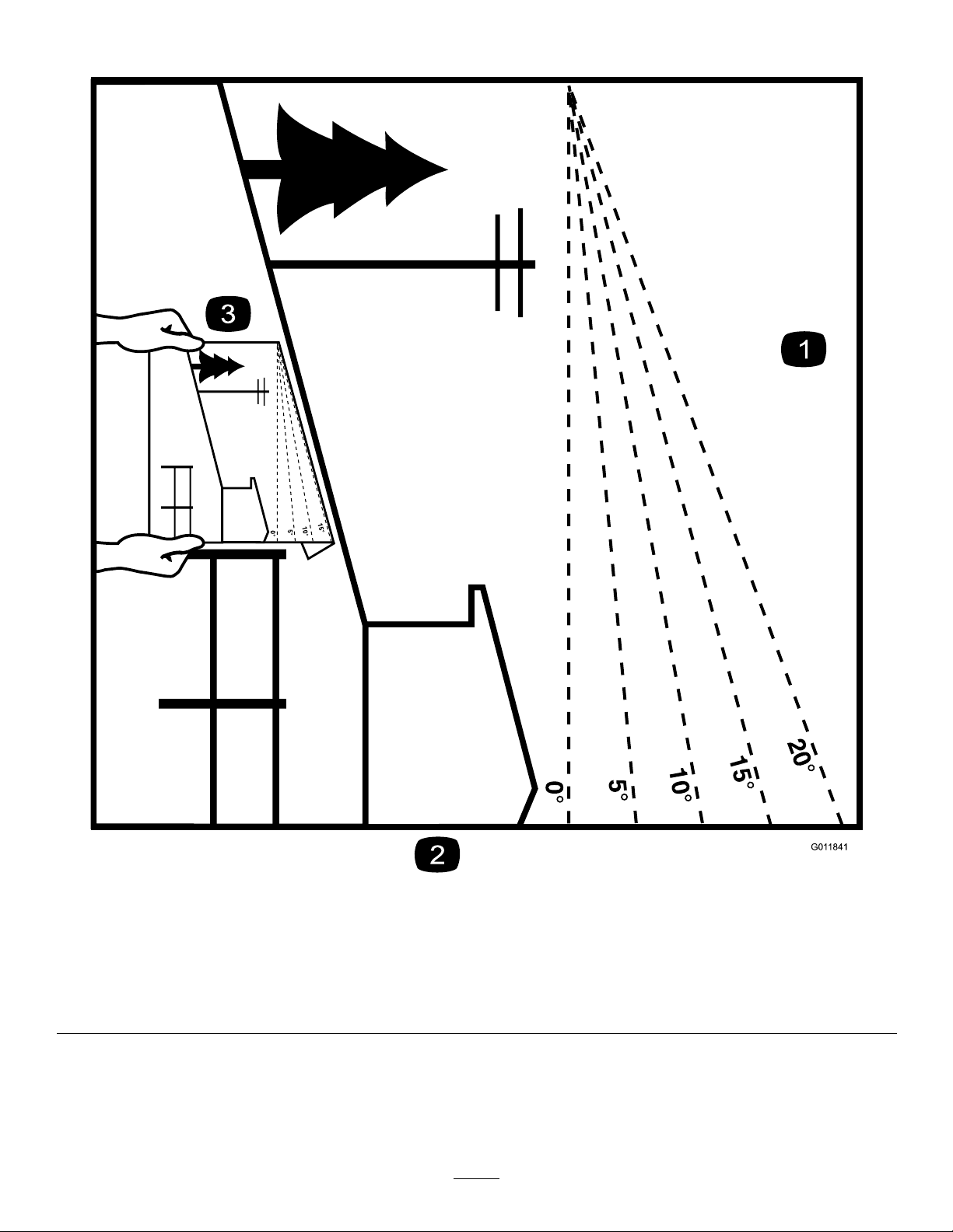
SlopeIndicator
G011841
Figure3
Thispagemaybecopiedforpersonaluse.
1.Themaximumslopeyoucansafelyoperatethemachineonis15degrees.Usetheslopecharttodeterminethedegreeofslope
ofhillsbeforeoperating.Donotoperatethismachineonaslopegreaterthan15degrees.Foldalongtheappropriateline
tomatchtherecommendedslope.
2.Alignthisedgewithaverticalsurface,atree,building,fencepole,etc.
3.Exampleofhowtocompareslopewithfoldededge.
7
Page 8
SafetyandInstructional
Decals
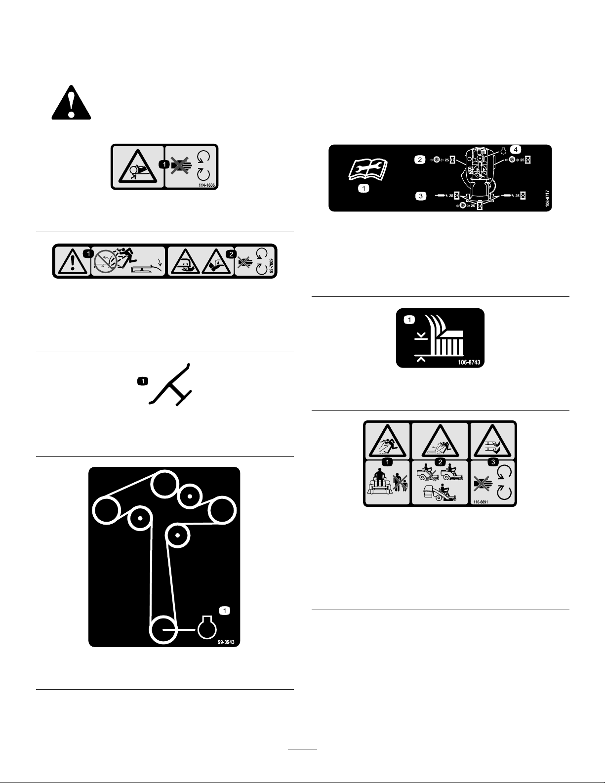
Safetydecalsandinstructionsareeasilyvisibletotheoperatorandarelocatednearanyareaof
potentialdanger.Replaceanydecalthatisdamagedorlost.
114-1606
1.Entanglementhazard,belt—keepallguardsinplace.
93-7009
1.Warning—don’toperatethemowerwiththedeectorupor
removed;keepthedeectorinplace.
2.Cutting/dismembermenthazardofhandorfoot,mower
blade—stayawayfrommovingparts.
106-8717
1.Readtheinstructionsbeforeservicingorperforming
maintenance.
2.Checktirepressureevery25operatinghours.
3.Greaseevery25operatinghours.
4.Engine
Manufacturer’sMark
1.Indicatesthebladeisidentiedasapartfromtheoriginal
machinemanufacturer.
99-3943
1.Engine
106-8743
1.Heightofcut
110-6691
1.Thrownobjecthazard—keepbystandersasafedistance
fromthemachine.
2.Thrownobjecthazard,mower—donotoperatewithoutthe
deector,dischargecover,orgrasscollectionsystemin
place.
3.Cutting/dismembermentofhandorfoot—stayawayfrom
movingparts.
8
Page 9
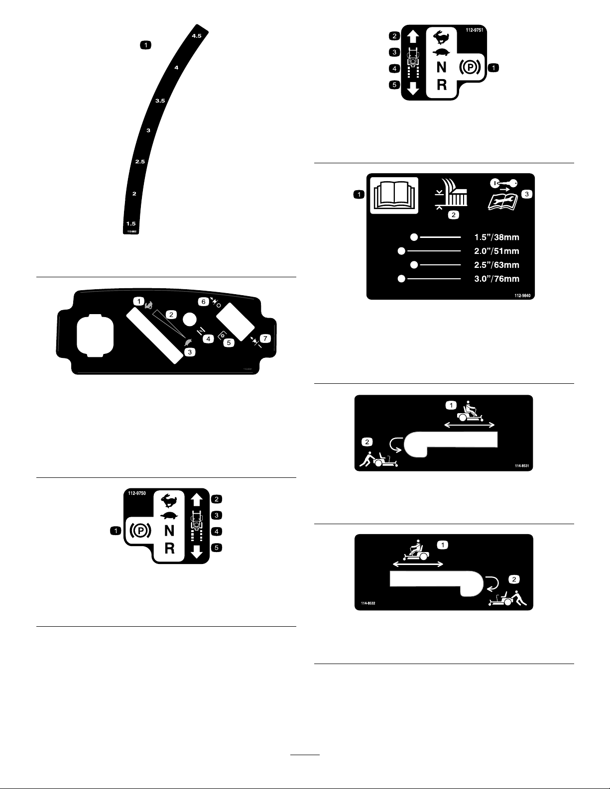
112-9802
1.Height-of-cut
115-2501
1.Fast
2.Continuousvariable
setting
3.Slow7.Bladecontrolswitch—On
4.Choke
5.Powertake-off(PTO),
Bladecontrolswitchon
somemodels
6.Bladecontrolswitch—Off
112-9751
1.Parkingposition4.Neutral
2.Fast5.Reverse
3.Slow
112-9840
1.ReadtheOperator’s
Manual.
2.Heightofcut
3.Removetheignitionkey
andreadtheinstructions
beforeservicingor
performingmaintenance.
112-9750
1.Parkingposition4.Neutral
2.Fast5.Reverse
3.Slow
1.Bypassleverpositionfor
operatingthemachine
1.Bypassleverpositionfor
operatingthemachine
9
114-8531
2.Bypassleverpositionfor
pushingthemachine
114-8532
2.Bypassleverpositionfor
pushingthemachine
Page 10
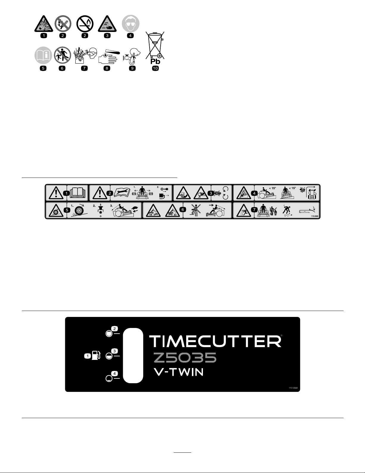
BatterySymbols
Someorallofthesesymbolsareonyourbattery
1.Explosionhazard
2.Nore,opename,or
smoking.
3.Causticliquid/chemical
burnhazard
4.Weareyeprotection9.Flusheyesimmediately
5.ReadtheOperator’s
Manual.
6.Keepbystandersasafe
distancefromthebattery.
7.Weareyeprotection;
explosivegasescan
causeblindnessandother
injuries
8.Batteryacidcancause
blindnessorsevereburns.
withwaterandgetmedical
helpfast.
10.Containslead;donot
discard.
115-2469
1.Warning—readtheOperator’sManual.
2.Warning—readtheinstructionsbeforeservicingorperformingmaintenance;movethemotioncontrolleverstothepark(brake)
position,removetheignitionkeyanddisconnectthesparkplugwire.
3.Cutting/dismembermenthazard,mowerblade;entanglementhazard,belt—donotopenorremovesafetyshieldswhileengineis
running.
4.Tippinghazard—donotmowslopesgreaterthan15degrees,avoidsuddenandsharpturnswhileonslopes.
5.Lossoftraction/controlhazard,slopes—lossoftraction/controlonaslope,disengagethebladecontrolswitch(PTO),proceed
offtheslopeslowly.
6.Crushing/dismembermenthazardofbystanders,reversing;crushing/dismembermenthazardofbystanders—donotcarry
passengers,lookbehindanddownwhenreversing.
7.Thrownobjecthazard—keepbystandersasafedistancefromthemachine,pickupdebrisbeforeoperating,keepdeectorinplace.
1.Fuel2.Full
117-7222
3.Half
4.Empty
10
Page 11
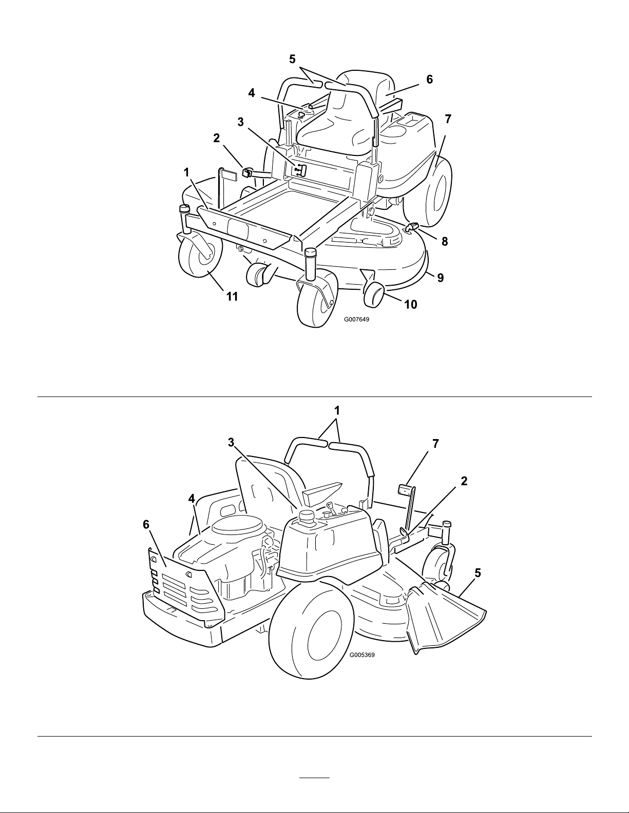
ProductOverview
1.Footrest
2.Heightofcutlever
3.Fuelgauge
4.Controlpanel
5.Motioncontrollevers
6.Operatorseat
Figure4
7.Reardrivewheel10.Anti-scalproller
8.Washouttting
9.Mowerdeck
11.Frontcasterwheel
1.Motioncontrollevers
2.Heightofcutlever
Figure5
3.Gastankcap5.Deector
4.Engine6.Engineguard
11
7.Footassistpedal
Page 12
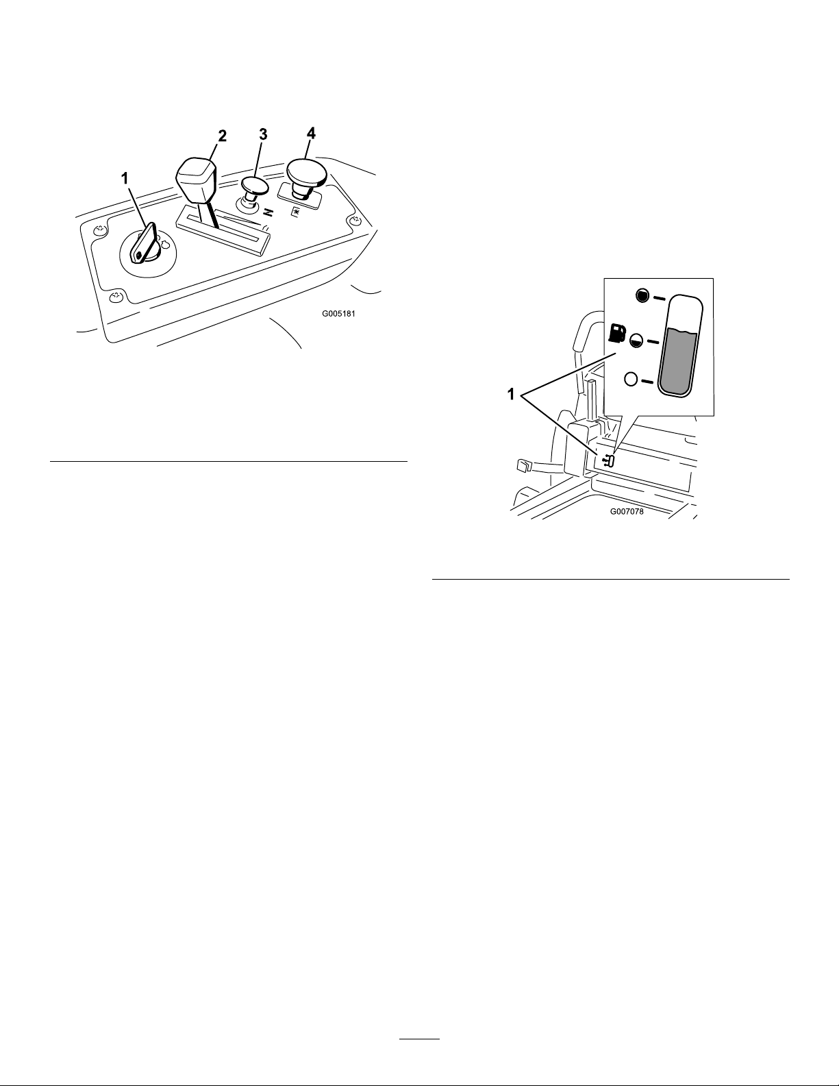
Controls
G005181
1
2
3
4
BecomefamiliarwithallofthecontrolsinFigure4,
Figure5,andFigure6beforeyoustarttheengineand
operatethemachine.
Figure6
ControlPanel
backwardturnsthewheelonthesamesideforwardorin
reverse;wheelspeedisproportionaltotheamountthe
leverismoved.Movethecontrolleversoutwardfrom
thecentertotheparkpositionandexitthemachine
Figure16).Alwayspositionthemotioncontrollevers
(
intotheparkpositionwhenyoustopthemachineor
leaveitunattended.
FuelGauge
Thefuelwindowlocatedbelowtheoperatorposition
canbeusedtoverifythelevelofgasolineinthetank
Figure7).
(
1.Ignitionswitch
2.Throttlecontrol4.Bladecontrolswitch
3.Chokecontrol
(powertake-off)
IgnitionSwitch
Theignitionswitchhasthreepositions,Off,Runand
Start.ThekeywillturntoStartandmovebackto
Runuponrelease.TurningthekeytotheOffposition
willstoptheengine;however,alwaysremovethekey
whenleavingthemachinetopreventsomeonefrom
accidentallystartingtheengine(
Figure6).
ThrottleControl
Thethrottlecontrolstheenginespeedandithasa
continuousvariablesettingfromSlowtoFast(
Figure6).
ChokeControl
PullupontheChokecontroluntilitstopstochokethe
engine(Figure6).PushdownontheChokecontrolfor
normalengineoperation
BladeControlSwitch(PowerTake-Off)
Thebladecontrolswitch,representedbyapower
take-off(PTO)symbol,engagesanddisengagespower
tothemowerblades(Figure6).
MotionControlLeversandPark
Position
Figure7
1.Fuelgaugewindow
Height-of-CutLever
Theheightofcutleverallowstheoperatortolower
andraisethedeckfromtheseatedposition.Whenthe
leverismovedup,towardtheoperatorthedeckisraised
fromthegroundandwhenmoveddown,awayfromthe
operatoritisloweredtowardtheground.Onlyadjust
theheightofcutwhilemachineisnotmoving(
Figure4).
FootAssistPedal
Thefootassistpedalallowstheoperatortosupportthe
weightofthedeckwiththeirlegduringadjustingthe
deckheightviatheheight-of-cutlever(Figure5).
Themotioncontrolleversarespeedsensitivecontrolsof
independentwheelmotors.Movingaleverforwardor
12
Page 13
Operation
Note:Determinetheleftandrightsidesofthe
machinefromthenormaloperatingposition.
ThinkSafetyFirst
Pleasecarefullyreadallofthesafetyinstructionsand
decalsinthesafetysection.Knowingthisinformation
couldhelpyou,yourfamily,petsorbystandersavoid
injury.
DANGER
Mowingonwetgrassorsteepslopescancause
slidingandlossofcontrol.
Wheelsdroppingoveredgescancauserollovers,
whichmayresultinseriousinjury,deathor
drowning.
Alossoftractionisalossofsteeringcontrol.
Toavoidlossofcontrolandpossibilityofrollover:
•Donotmowneardrop-offsornearwater.
•Donotmowslopesgreaterthan15degrees.
•Reducespeedanduseextremecautionon
slopes.
•Whenmowingslopes,graduallyworkfrom
lowertohigherareasontheincline.
•Avoidsuddenturnsorrapidspeedchanges.
Figure8
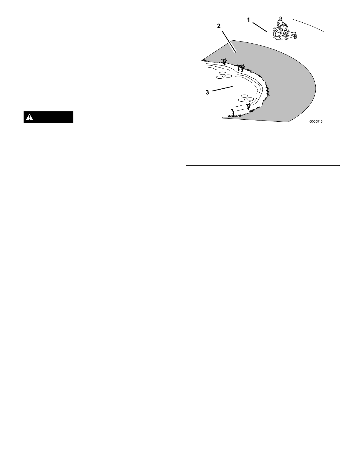
1.SafeZone-usetheTimeCutterhere
2.Usewalkbehindmowerand/orhandtrimmerneardrop-offs
andwater.
3.Water
RecommendedGasoline
UseUNLEADEDRegularGasolinesuitablefor
automotiveuse(87pumpoctaneminimum).Leaded
regulargasolinemaybeusedifunleadedregularisnot
available.
Important:Neverusemethanol,gasoline
containingmethanol,orgasoholcontainingmore
than10percentethanolbecausethefuelsystem
couldbedamaged.Donotmixoilwithgasoline.
•Turnup,intoaninclinewhenchanging
directionsonslopes.Turningdowntheslope
reducestraction.
•Attachmentschangethehandling
characteristicsofthemachine.Use
extracautionwhenusingattachmentswiththe
machine.
13
Page 14

DANGER
WARNING
Incertainconditions,gasolineisextremely
ammableandhighlyexplosive.Areorexplosion
fromgasolinecanburnyouandothersandcan
damageproperty.
•Fillthefueltankoutdoors,inanopenarea,
whentheengineiscold.Wipeupanygasoline
thatspills.
•Neverllthefueltankinsideanenclosedtrailer.
•Donotllthefueltankcompletelyfull.Add
gasolinetothefueltankuntilthebodyofthe
tankisfullbutfueldoesnotlltheneckof
thetank.Thisemptyspaceinthetankallows
gasolinetoexpand.
•Neversmokewhenhandlinggasoline,andstay
awayfromanopenameorwheregasoline
fumesmaybeignitedbyaspark.
•Storegasolineinanapprovedcontainerand
keepitoutofthereachofchildren.Neverbuy
morethana30-daysupplyofgasoline.
•Donotoperatewithoutentireexhaustsystem
inplaceandinproperworkingcondition.
DANGER
Incertainconditionsduringfueling,static
electricitycanbereleasedcausingasparkwhich
canignitethegasolinevapors.Areorexplosion
fromgasolinecanburnyouandothersandcan
damageproperty.
•Alwaysplacegasolinecontainersontheground
awayfromyourvehiclebeforelling.
Gasolineisharmfulorfatalifswallowed.
Long-termexposuretovaporscancauseserious
injuryandillness.
•Avoidprolongedbreathingofvapors.
•Keepfaceawayfromnozzleandgastankor
conditioneropening .
•Keepgasawayfromeyesandskin.
UsingStabilizer/Conditioner
Useafuelstabilizer/conditionerinthemachineto
providethefollowingbenets:
•Keepsgasolinefreshduringstorageof30daysor
less.Forlongerstorageitisrecommendedthatthe
fueltankbedrained.
•Cleanstheenginewhileitruns.
•Eliminatesgum-likevarnishbuildupinthefuel
system,whichcauseshardstarting.
Addthecorrectamountofgasstabilizer/conditioner
tothegas.
Note:Afuelstabilizer/conditionerismosteffective
whenmixedwithfreshgasoline.Tominimizethe
chanceofvarnishdepositsinthefuelsystem,usefuel
stabilizeratalltimes.
Gasoline/Alcoholblends
Gasohol(upto10percentethylalcohol,90percent
unleadedgasolinebyvolume)isapprovedforfueluse
bytheenginemanufacturer.Othergasoline/alcohol
blends,suchasE85,arenotapproved.
•Donotllgasolinecontainersinsideavehicle
oronatruckortrailerbedbecauseinterior
carpetsorplastictruckbedlinersmayinsulate
thecontainerandslowthelossofanystatic
charge.
•Whenpractical,removegas-powered
equipmentfromthetruckortrailerandrefuel
theequipmentwithitswheelsontheground.
•Ifthisisnotpossible,thenrefuelsuch
equipmentonatruckortrailerfromaportable
container,ratherthanfromagasolinedispenser
nozzle.
•Ifagasolinedispensernozzlemustbeused,
keepthenozzleincontactwiththerimofthe
fueltankorcontaineropeningatalltimesuntil
fuelingiscomplete.
Gasoline/Etherblends
MethylTertiaryButylEther(MTBE)andunleaded
gasolineblends(uptoamaximumof15percentMTBE
byvolume)areapprovedforfuelusebytheengine
manufacturer.Othergasoline/etherblendsarenot
approved.
FuelGauge
Usethefuelwindowbelowtheoperatortoverifythe
levelofgasolinebeforellingthetank(Figure9).
14
Page 15
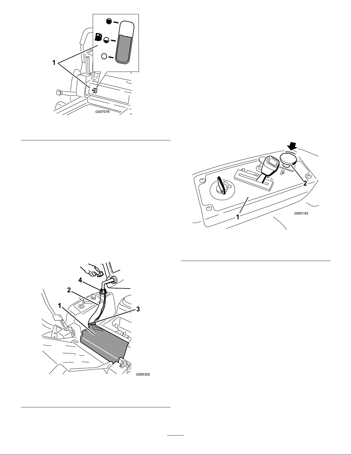
Figure9
G005302
1
2
3
4
1.Fuelgaugewindow
FillingtheFuelT ank
1.Shuttheengineoffandsetthemotioncontrolsto
theparkposition.Raisetheseatsothegastankis
visiblewhilefueling.
CheckingtheEngineOilLevel
Beforeyoustarttheengineandusethemachine,check
theoillevelintheenginecrankcase;refertoChecking
theOilLevelintheEngineMaintenancesection.
StartingandStoppingthe
Engine
StartingtheEngine
1.Sitdownontheseatandmovethemotioncontrols
outwardtotheparkposition.
2.Disengagethebladesbymovingthebladecontrol
switchtoOff(
Figure11)
2.Cleanaroundthefueltankcapandremovethecap.
3.Addunleadedregulargasolineuntilthebodyofthe
tankisfullbutfueldoesnotlltheneckofthe
Figure10).Thisspaceintheneckofthetank
tank(
allowsgasolinetoexpand.Donotllthefueltank
completelyfull.
4.Installthefueltankcapsecurely.Wipeupany
gasolinethatmayhavespilled.
Figure11
1.Controlpanel2.Bladecontrolswitch—Off
position
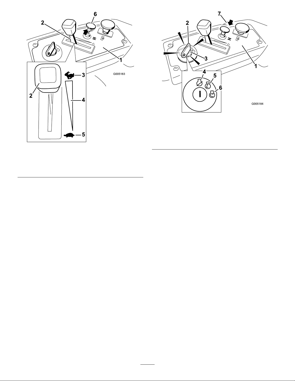
3.PullupontheChokecontrolbeforestartingacold
engine(Figure12).
Note:Awarmorhotenginemaynotrequire
choking.
Figure10
1.Gastankbody
2.Gastankneck4.Gastankopening
3.Filltohere,approximately
15
Page 16
G005183
1
2
2
1
2
2
3
4
5
6
Figure12
G005184
1
2
3
4
5
6
1
2
3
4
5
6
7
1.Controlpanel4.Continuousvariable
2.Throttle
3.Fast
setting
5.Slow
6.Chokecontrol
4.TurntheignitionkeytoStarttoenergizethestarter.
Whentheenginestarts,releasethekey(Figure13).
Important:Donotengagethestarterformore
than10secondsatatime.Iftheenginefails
tostart,allowa60secondcool-downperiod
betweenattempts.Failuretofollowthese
instructionscandamagethestartermotor.
Figure13
1.Controlpanel
2.Ignitionkey—runposition
3.Ignitionkey—startposition
4.Off
5.Run
6.Start
7.Chokecontrol
5.Aftertheenginestarts,pushdownontheChoke
control(Figure13).Iftheenginestallsorhesitates,
pullupontheChokecontrolandlettheenginerun
forafewseconds.ThenpushdownontheChoke
control.Repeatthisasrequired.
OperatingtheBlades
Thebladecontrolswitch,representedbyapower
take-off(PTO)symbol,engagesanddisengagespower
tothemowerblades.Thisswitchcontrolspowertoany
attachmentsthatdrawpowerfromtheengine,including
themowerdeckandcuttingblades.
EngagingtheBlades
Important:Donotengagethebladeswhen
parkedintallgrass.Beltorclutchdamagecan
occur.
1.Releasepressureonthemotioncontrolleversand
placethemachineinneutral.
2.MovethethrottletotheFastposition.
Note:Alwaysengagethebladeswiththethrottle
intheFastposition.
3.Pulluponthebladecontrolswitchtomoveitto
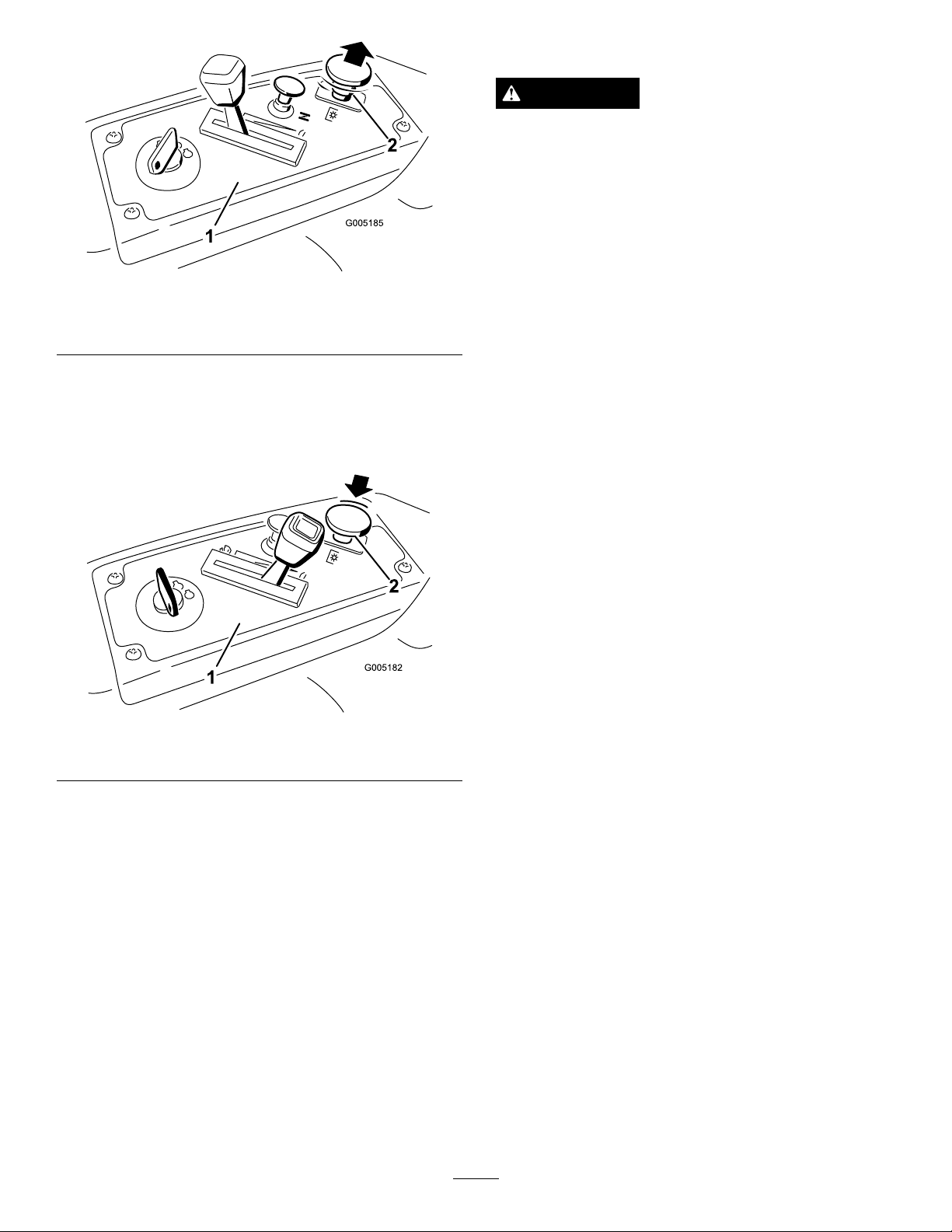
16
theOnpositionandengagetheblades(Figure14).
Page 17
G005185
121
2
Figure14
1.Controlpanel2.Bladecontrolswitch—On
position
DisengagingtheBlades
Pushdownonthebladecontrolswitchtomoveitto
theOffpositionanddisengagetheblades(Figure15).
TheSafetyInterlockSystem
WARNING
Ifsafetyinterlockswitchesaredisconnectedor
damagedthemachinecouldoperateunexpectedly
causingpersonalinjury.
•Donottamperwiththeinterlockswitches.
•Checktheoperationoftheinterlockswitches
dailyandreplaceanydamagedswitchesbefore
operatingthemachine.
UnderstandingtheSafetyInterlock
System
Thesafetyinterlocksystemisdesignedtopreventthe
enginefromstartingunless:
•Thebladesaredisengaged.
•Themotioncontrolleversareintheparkposition.
Thesafetyinterlocksystemalsoisdesignedtostop
theenginewhenthecontrolleversareoutofthepark
positionandyourisefromtheseatwhentheblades
areengaged.
Figure15
1.Controlpanel2.Bladecontrolswitch—Off
StoppingtheEngine
1.Disengagethebladesbymovingthebladecontrol
switchtoOff(Figure15).
2.MovethethrottlelevertobetweenFastandhalf
throttle(Figure15).
3.TurntheignitionkeytoOff(Figure11)andremove
thekey .
TestingtheSafetyInterlockSystem
Testthesafetyinterlocksystembeforeyouusethe
machineeachtime.Ifthesafetysystemdoesnot
operateasdescribedbelow,haveanAuthorizedService
Dealerrepairthesafetysystemimmediately .
1.Whilesittingontheseat,withthecontrolleversin
parkposition,andmovethebladecontrolswitch
toOn.Trystartingtheengine;theengineshould
notcrank.
2.Whilesittingontheseat,movethebladecontrol
switchtoOff.Moveeithermotioncontrollever
tothecenter,unlockedposition.Trystartingthe
engine;theengineshouldnotcrank.Repeatwith
theothermotioncontrollever.
3.Whilesittingontheseat,movethebladecontrol
switchtoOff,andlockthemotioncontrolleversin
theparkposition.Starttheengine.Whiletheengine
isrunning,engagethebladecontrolswitch,andrise
slightlyfromtheseat;theengineshouldstop.
4.Whilesittingontheseat,movethebladecontrol
switchtoOff,andlockthemotioncontrollevers
intheparkposition.Starttheengine.Whilethe
engineisrunning,movethemotioncontrollevers
tothecenter,unlockedposition,engagetheblade
controlswitch,andriseslightlyfromtheseat;the
engineshouldstop.
17
Page 18
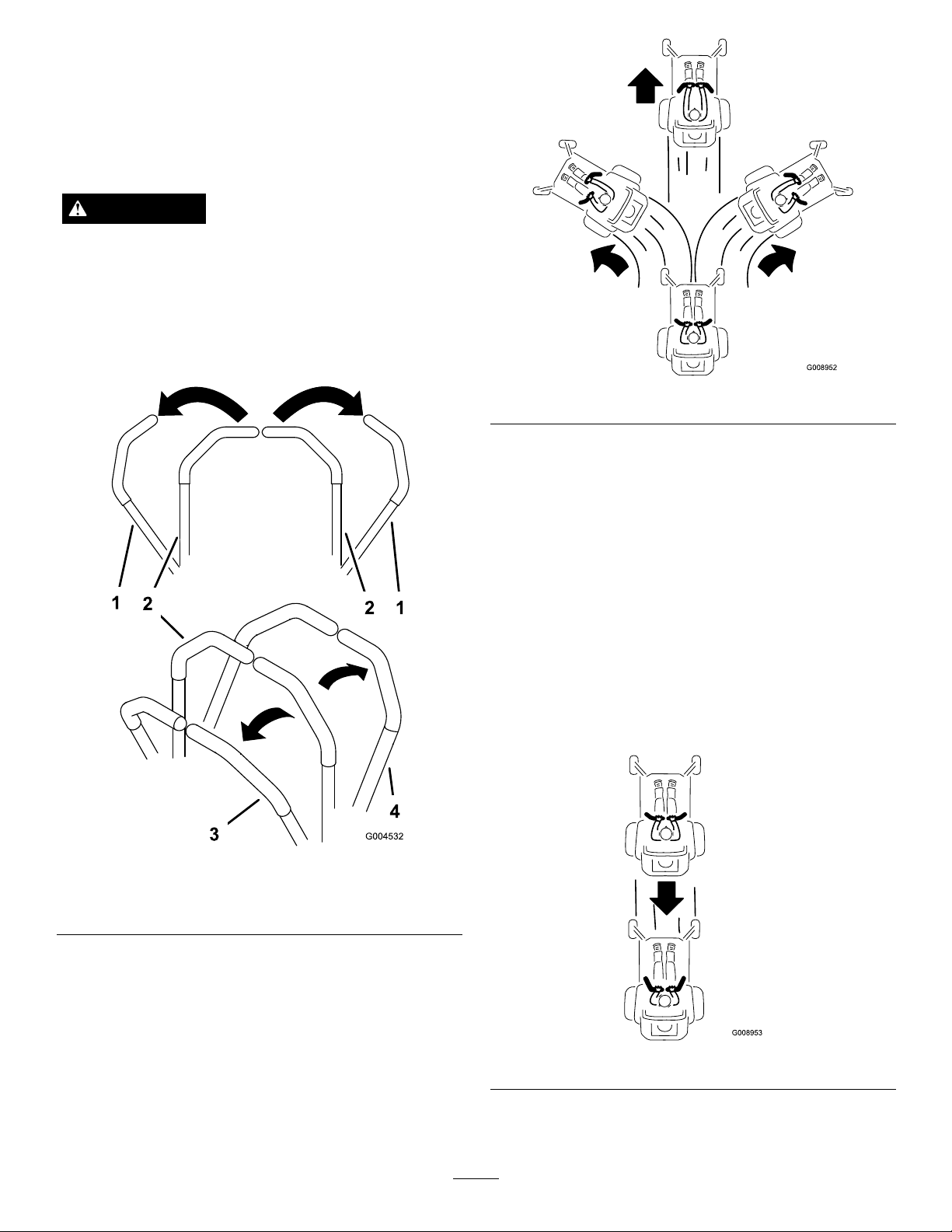
DrivingForwardorBackward
G008952
G008953
Thethrottlecontrolregulatestheenginespeedas
measuredinrpm(revolutionsperminute).Place
thethrottlecontrolintheFastpositionforbest
performance.Alwaysoperateinthefullthrottle
position.
WARNING
Themachinecanspinveryrapidly.Theoperator
maylosecontrolofthemachineandcausepersonal
injuryordamagetothemachine.
•Usecautionwhenmakingturns.
•Slowthemachinedownbeforemakingsharp
turns.
Figure17
Togostraight,applyequalpressuretobothmotion
controllevers(Figure16).
Toturn,releasepressureonthemotioncontrollever
towardthedirectionyouwanttoturn(
Figure16).
1.Park(brake)position
2.Centerunlockposition
Forward
Thefartheryoumovethemotioncontrolleversin
eitherdirection,thefasterthemachinewillmovein
thatdirection.
Tostop,pullthemotioncontrolleverstoneutral.
Backward
1.Movetheleverstothecenter,unlockedposition.
2.Togobackward,slowlypullthemotioncontrol
leversrearward(Figure18).
Figure16
3.Forward
4.Backward
1.Movetheleverstothecenter,unlockedposition.
2.Togoforward,slowlypushthemotioncontrol
leversforward(Figure16).
Figure18
Togostraight,applyequalpressuretobothmotion
controllevers(Figure18).
18
Page 19
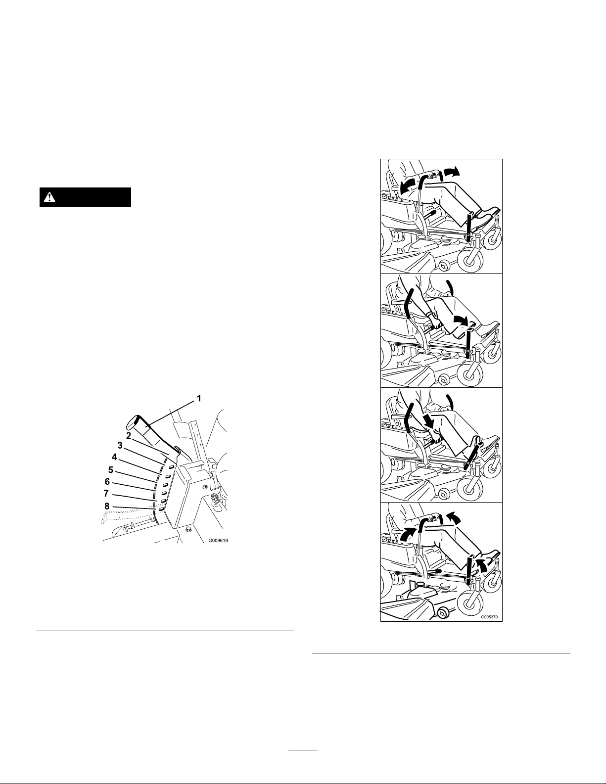
Toturn,releasethepressureonthemotioncontrol
G009619
1
2
3
4
5
6
7
8
levertowardthedirectionyouwanttoturn.
Tostop,pushthemotioncontrolleverstoneutral.
StoppingtheMachine
UsingtheFootAssistPedal
Thefootassistpedalcanbeusedwiththeheightofcut
levertohelpadjustthedeckheight.
1.Entertheoperator’sposition.Placeafootonthe
footassistpedalandapplypressure.
Tostopthemachine,movethemotioncontrolleversto
neutralandoutwardtotheparkposition,disengagethe
bladecontrolswitch,ensurethethrottleisinthefast
position,andturntheignitionkeytooff.Rememberto
removethekeyfromtheignitionswitch.
WARNING
Childrenorbystandersmaybeinjuredifthey
moveorattempttooperatethemowerwhileitis
unattended.
Alwaysremovetheignitionkeyandmovethe
motioncontrolleversoutwardtotheparkposition
whenleavingthemachineunattended,evenifjust
forafewminutes.
AdjustingtheHeightofCut
1.Raisetheheight-of-cutlevertothetransport
position,cuttingheightpositionG(alsothe
4-1/2inch[115mm])(
Figure19).
2.Whilemaintainingpressureonthepedal,pull
inwardandupontheheight-of-cutleverandmove
ittothedesiredposition.
Figure19
1.Height-of-cutlever5.3inch(76mm)
2.4.5inch(115mm),
Transportposition
3.4inch(102mm)7.2inch(51mm)
4.3.5inch(89mm)8.1.5inch(38mm)
6.2.5inch(64mm)
Figure20
2.Toadjusttheheightofcut,pullinwardandupon
theleverandmoveittothedesiredposition.
19
Page 20
PositioningtheSeat
G005062
1
2
3
4
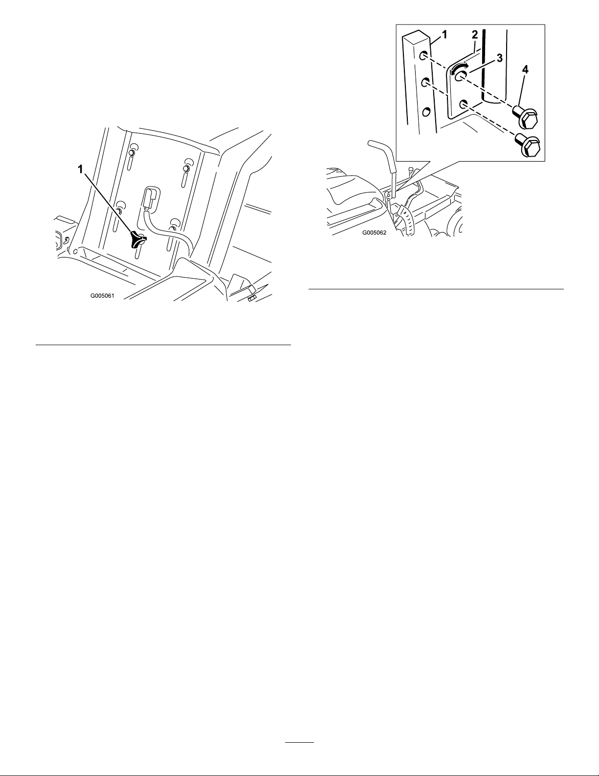
Theseatcanmoveforwardandbackward.Positionthe
seatwhereyouhavethebestcontrolofthemachine
andaremostcomfortable.
1.Raisetheseatandloosentheadjustmentknobjust
enoughthatseatcanmove(Figure21).
Figure22
1.Controlarmshaft3.Slotted,upperhole
2.Controllever
4.Bolt
Figure21
1.Adjustmentknob
2.Movetheseattothedesiredpositionandtighten
theknob.
AdjustingtheMotionControl
Levers
AdjustingtheHeight
Themotioncontrolleverscanbeadjustedhigheror
lowerformaximumoperatorcomfort.
1.Removethe2boltsholdingthecontrollevertothe
Figure22).
controlarmshaft(
2.Movethecontrollevertothenextsetofholes.
Securetheleverwiththe2bolts(Figure22).
3.Repeattheadjustmentfortheoppositecontrol
lever.
AdjustingtheTilt
Themotioncontrolleverscanbetiltedforeoraftfor
maximumoperatorcomfort.
1.Loosentheupperboltholdingthecontrolleverto
thecontrolarmshaft.
2.Loosenthelowerboltjustenoughtopivotthe
controlleverforeoraft(Figure22).Tightenboth
boltstosecurethecontrolinthenewposition.
3.Repeattheadjustmentfortheoppositecontrol
lever.
PushingtheMachinebyHand
Important:Alwayspushthemachinebyhand.
Nevertowthemachinebecausedamagemay
occur.
ToPushtheMachine
1.Parkthemachineonalevelsurfaceanddisengage
thebladecontrolswitch.
2.Movethemotioncontrolleversoutwardtopark
position,stoptheengine,removethekey,andwait
forallmovingpartstostopbeforeleavingthe
operatingposition.
3.Locatethebypassleversattherearofthemachine,
ontheleftandrightsideoftheframe.
20
Page 21
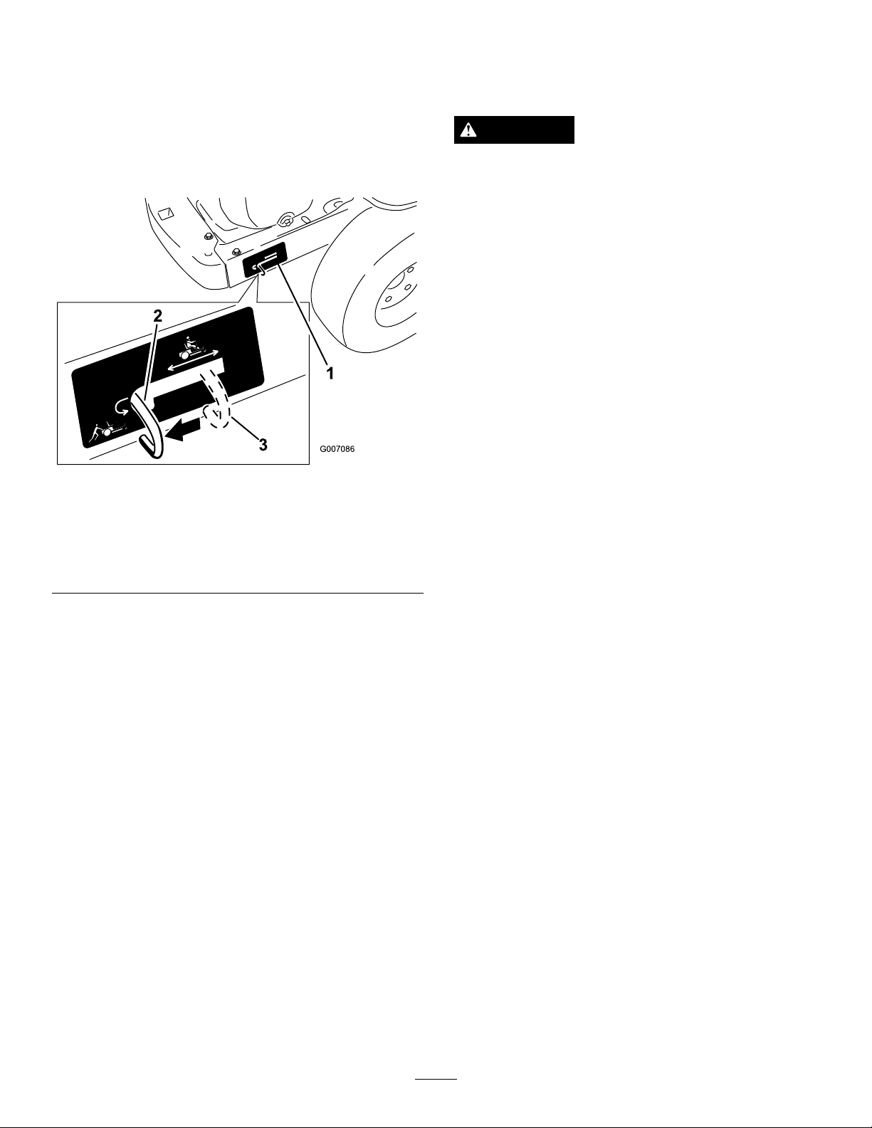
4.Movethebypassleversrearwardandthendown
tolocktheminplaceasshowninFigure23to
disengagethewheelmotors.Repeatthisoneach
sideofthemachine.
GrassDeector
Themowerhasahingedgrassdeectorthatdisperses
clippingstothesideanddowntowardtheturf.
5.Movethemotioncontrolleversinwardtothe
neutralposition.
Themachineisnowabletobepushedbyhand.
Figure23
Rightsideshown
1.Bypassleverlocation
2.Leverpositionforpushing
themachine
3.Leverpositionfor
operatingthemachine
ToOperatetheMachine
Movethebypassleversupwardandpushthemforward,
tothemiddleofthehorizontalslot(
engagethewheelmotors.
Figure23)to
DANGER
Withoutthegrassdeector,dischargecover,or
completegrasscatcherassemblymountedin
place,youandothersareexposedtobladecontact
andthrowndebris.Contactwithrotatingmower
blade(s)andthrowndebriswillcauseinjuryor
death.
•Neverremovethegrassdeectorfromthe
mowerbecausethegrassdeectorroutes
materialdowntowardtheturf.Ifthe
grassdeectoriseverdamaged,replaceit
immediately.
•Neverputyourhandsorfeetunderthemower.
•Nevertrytocleardischargeareaormower
bladesunlessyoumovethebladecontrolswitch
toOffandrotatetheignitionkeytoOff.Also
removethekeyandpullthewireoffthespark
plug(s).
ConvertingtoSideDischarge
Themowerdeckandmowerbladesshippedwith
thismachineweredesignedforoptimummulching
performance.Sidedischargeperformancecanbe
improvedbyreplacingthemulchingbladeswith
standardcuttingbladesobtainedfromyourlocal
authorizedT orodealer.T omaintainoptimummulching
performance,alwaysinstallthemulchingbladesthatare
shippedwiththisunitwhenchangingbacktomulching
operation.
RemovingtheRightBafeforSide
Discharge
Note:Ifthebaggerattachmentisaddedthemachine,
standardbladesmustbeinstalledforproperbagging
function.ContactyourlocalauthorizedTorodealer
fortheproperpartnumber.
1.Parkthemachineonalevelsurfaceanddisengage
thebladecontrolswitch.
2.Movethemotioncontrolleversoutwardtopark
position,stoptheengine,removethekey,andwait
forallmovingpartstostopbeforeleavingthe
operatingposition.
3.Removetherightmowerblade.RefertotheMower
Maintenancesection.
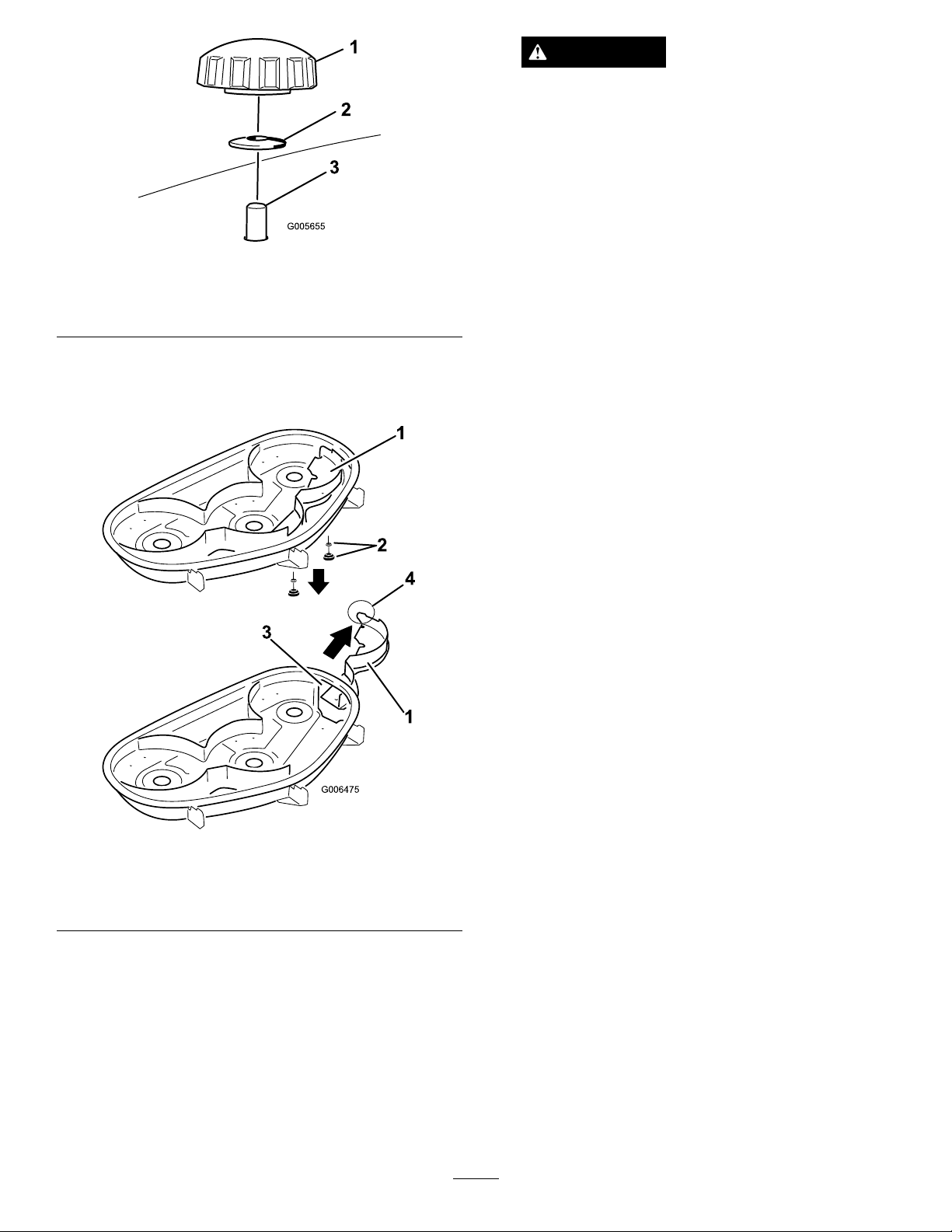
4.Removethe2knobsandcurvedwashersthatsecure
therightbafetothemowerasshownin
21
Figure24.
Page 22
G006475
1
2
3
4
1
WARNING
Openholesinthemowerexposeyouandothers
tothrowndebriswhichcancausesevereinjury.
•Neveroperatethemowerwithouthardware
mountedinallexposedholesinthemower
housingvisiblefromtheoperator’sposition.
•Installthehardwareinthemountingholes
whenyouremovethemulchingbafe.
Figure24
1.Knob
2.Curvedwasher
3.Bafestudcomingthrough
themower
5.Removetherightbafeandlowerthegrass
deectoroverthedischargeopeningasshownin
Figure25andFigure24.
7.Installtherightmowerblade.RefertotheMower
Maintenancesection.
8.Lowerthegrassdeectoroverthedischarge
opening.
Important:Ensurethemowerhasahinged
grassdeectorthatdispersesclippingstothe
sideanddowntowardtheturf,whileinside
dischargemode.
InstallingtheRightBafeforMulching
1.Parkthemachineonalevelsurfaceanddisengage
thebladecontrolswitch.
2.Movethemotioncontrolleversoutwardtopark
position,stoptheengine,removethekey,andwait
forallmovingpartstostopbeforeleavingthe
operatingposition.
3.Removetherightmowerblade.RefertotheMower
Maintenancesection.
4.Slidetherightbafethroughthedischargeopening
andsecureitusing2knobsandcurvedwashers
(cuppedsidefacingthemower)asshownin
Figure24andFigure25.
Figure25
1.Rightbafe
2.Curvedwasherandknob4.Tab(mustremainoutside
6.Installthefastenersintotheholesinthetopofthe
mowertopreventyingdebris.
3.Dischargeopening
ofthemower)
Important:Ensurethatthetabonthefarright
sideoftherightbafeisoutsideofthemower
andisushwiththemowerwall.
5.Installtherightmowerblade.RefertotheMower
Maintenancesection.
OperatingTips
FastThrottleSetting
Forbestmowingandmaximumaircirculation,operate
theengineattheFastposition.Airisrequiredto
thoroughlycutgrassclippings,sodonotsetthe
height-of-cutsolowastototallysurroundthemower
byuncutgrass.Alwaystrytohaveonesideofthe
mowerfreefromuncutgrass,whichallowsairtobe
drawnintothemower.
22
Page 23

CuttingaLawnfortheFirstTime
Cutgrassslightlylongerthannormaltoensurethatthe
cuttingheightofthemowerdoesnotscalpanyuneven
ground.However,thecuttingheightusedinthepastis
generallythebestonetouse.Whencuttinggrasslonger
thansixinchestall,youmaywanttocutthelawntwice
toensureanacceptablequalityofcut.
Cut1/3oftheGrassBlade
Itisbesttocutonlyabout1/3ofthegrassblade.
Cuttingmorethanthatisnotrecommendedunless
grassissparse,oritislatefallwhengrassgrowsmore
slowly.
MowingDirection
Alternatemowingdirectiontokeepthegrassstanding
straight.Thisalsohelpsdisperseclippingswhich
enhancesdecompositionandfertilization.
MowatCorrectIntervals
lawn.Toavoidthis,moveontoapreviouslycutarea
withthebladesengaged.
KeeptheUndersideoftheMower
Clean
Cleanclippingsanddirtfromtheundersideofthe
moweraftereachuse.Ifgrassanddirtbuildupinside
themower,cuttingqualitywilleventuallybecome
unsatisfactory.
BladeMaintenance
Maintainasharpbladethroughoutthecuttingseason
becauseasharpbladecutscleanlywithouttearingor
shreddingthegrassblades.Tearingandshreddingturns
grassbrownattheedges,whichslowsgrowthand
increasesthechanceofdisease.Checkthecutterblades
dailyforsharpness,andforanywearordamage.File
downanynicksandsharpenthebladesasnecessary.If
abladeisdamagedorworn,replaceitimmediatelywith
agenuineTororeplacementblade.
Normally,moweveryfourdays.Butremember,
grassgrowsatdifferentratesatdifferenttimes.So
tomaintainthesamecuttingheight,whichisagood
practice,mowmoreofteninearlyspring.Asthegrass
growthrateslowsinmidsummer,mowlessfrequently.
Ifyoucannotmowforanextendedperiod,rstmow
atahighcuttingheight;thenmowagaintwodayslater
atalowerheightsetting.
CuttingSpeed
Toimprovecutquality,useaslowergroundspeed.
AvoidCuttingTooLow
Ifthecuttingwidthofthemoweriswiderthanthe
moweryoupreviouslyused,raisethecuttingheightto
ensurethatuneventurfisnotcuttooshort.
LongGrass
Ifthegrassiseverallowedtogrowslightlylongerthan
normal,orifitcontainsahighdegreeofmoisture,raise
thecuttingheighthigherthanusualandcutthegrassat
thissetting.Thencutthegrassagainusingthelower,
normalsetting.
WhenStopping
Ifthemachine’sforwardmotionmustbestoppedwhile
mowing,aclumpofgrassclippingsmaydropontoyour
23
Page 24

Maintenance
Note:Determinetheleftandrightsidesofthemachinefromthenormaloperatingposition.
RecommendedMaintenanceSchedule(s)
MaintenanceService
Interval
Aftertherst8hours
Beforeeachuseordaily
Every25hours
Every100hours
Every200hours
Beforestorage
MaintenanceProcedure
•Changetheengineoil.
•Checkthesafetyinterlocksystem.
•Checktheengineoillevel.
•Cleantheairintakescreen.
•Checkthecuttingblades.
•Inspectthegrassdeectorfordamage
•Cleanthemowerhousing.
•Greasealllubricationpoints.
•Checktirepressure.
•Checkthebeltsforwear/cracks.
•Servicethepaperelement.(moreoftenindusty ,dirtyconditions)
•Changetheengineoil.(moreoftenindusty,dirtyconditions)
•Checkthesparkplug(s).
•Replacethefuellter.
•Replacethepaperelement.(moreoftenindusty,dirtyconditions)
•Changetheoillter.(moreoftenindusty,dirtyconditions)
•Chargethebatteryanddisconnectbatterycables.
•Performallmaintenanceprocedureslistedabovebeforestorage.
•Paintanychippedsurfaces.
Important:Refertoyourengineoperator’smanualforadditionalmaintenanceprocedures.
CAUTION
Ifyouleavethekeyintheignitionswitch,someonecouldaccidentlystarttheengineandseriouslyinjure
youorotherbystanders.
Removethekeyfromtheignitionanddisconnectthewirefromthesparkplugbeforeyoudoany
maintenance.Setthewireasidesothatitdoesnotaccidentallycontactthesparkplug .
24
Page 25
Premaintenance
G005066
1
Lubrication
Procedures
GreasingtheBearings
RaisingtheSeat
Makesurethemotioncontrolleversarelockedinthe
parkposition.Lifttheseatforward.
Thefollowingcomponentscanbeaccessedbyraising
theseat:
•Serialplate
•Servicedecal
•Seatadjustmentknob
•Fuellter
•Batterycables
AccessingtheBattery
1.Raisetheseat.
2.RemovetheTORX
theleftcovertotheframeasshownin
®
headfasteners(T25)securing
Figure26.
ServiceInterval:Every25hours—Greaseall
lubricationpoints.
GreaseType:No.2GeneralPurposeLithiumBase
Grease
1.Parkthemachineonalevelsurfaceanddisengage
thebladecontrolswitch.
2.Movethemotioncontrolleversoutwardtothe
parkposition,stoptheengine,removethekey,and
waitforallmovingpartstostopbeforeleavingthe
operatingposition.
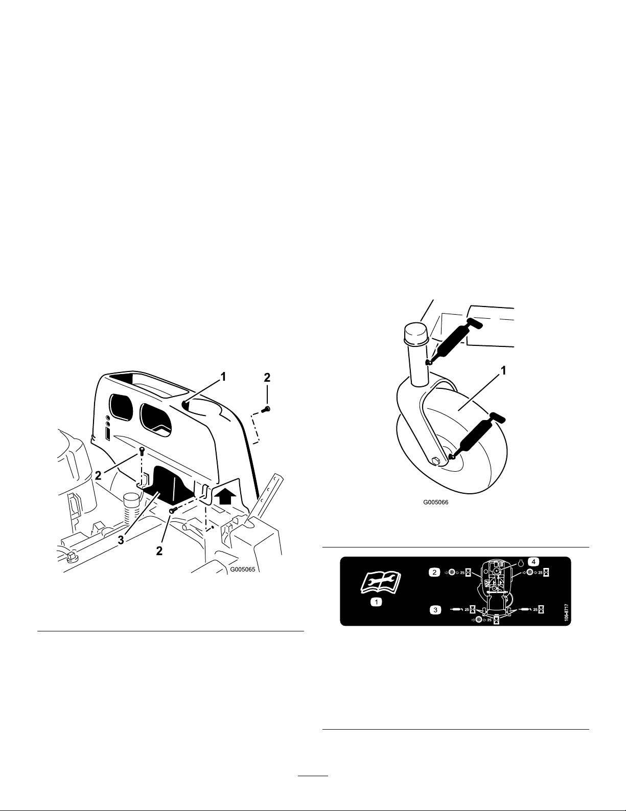
3.Cleanthegreasettings(
Figure27andFigure28)
witharag.Makesuretoscrapeanypaintoffofthe
frontofthetting(s).
Figure26
1.Leftcover
2.Torxheadfasteners(T25)
3.Battery
3.Lifttheplasticcoverawayfromthemachine.Retain
allfasteners.
Replacethecoverandsecureittotheframeusingthe
fastenersremovedpreviously.
1.Frontcastertire
1.Readtheinstructions
beforeservicingor
performingmaintenance.
2.Checktirepressureevery
25operatinghours.
25
Figure27
Figure28
Locatedontheseatpanunderside
3.Greaseevery25operating
hours.
4.Engine
Page 26
4.Connectagreaseguntoeachtting(Figure27and
G013402
1
2
3
Figure28).Pumpgreaseintothettingsuntilgrease
beginstooozeoutofthebearings.
5.Wipeupanyexcessgrease.
EngineMaintenance
ServicingtheAirCleaner
Note:Servicetheaircleanermorefrequently(every
fewhours)ifoperatingconditionsareextremelydusty
orsandy .
RemovingtheElement
1.Parkthemachineonalevelsurfaceanddisengage
thebladecontrol(PTO).
2.Movethemotioncontrolleverstothebrakeposition,
stoptheengine,removethekey,andwaitforall
movingpartstostopbeforeleavingtheoperating
position.
3.Cleanaroundtheaircleanertopreventdirtfrom
gettingintotheengineandcausingdamage.Loosen
thetwoplasticknobsonthecoverandremovethe
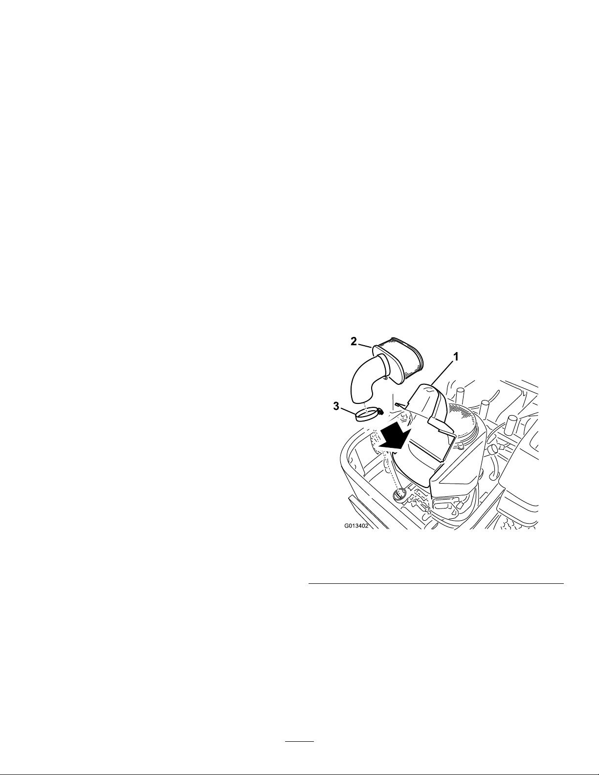
aircleanercover(
4.Unscrewthewingnutsandremovethepaper
element(Figure29).
Figure29).
Figure29
1.Cover
2.Paperelement
3.Hoseclamp
CleaningtheElement
ServiceInterval:Every100hours—Servicethepaper
element.(moreoftenindusty ,dirty
conditions)
Every200hours/Y early(whichever
comesrst)—Replacethepaper
element.(moreoftenindusty ,dirty
conditions)
26
Page 27
1.Lightlytaptheelementonaatsurfacetoremove
SAEV iscosityGrades
SAE40
SAE30
SAE10W– 30/ SAE10W– 30
-2002032406080100
-30-20-10010203040
°F
°C
STARTING TEMPERA TURERANGE ANTICIPATEDBEFORENEXT OIL CHANGE
SAE5W– 20
G010686
G009950
G008792
1
2
5
6
7
3
9
10
4
8
dustanddirt.
2.Inspecttheelementfortears,anoilylm,and
damagetotheseal.
Important:Nevercleanthepaperelementwith
pressurizedairorliquids,suchassolvent,gas,
orkerosene.Replacethepaperelementifitis
damagedorcannotbecleanedthoroughly.
ServicingtheEngineOil
OilType:Detergentoil(APIserviceSF ,SG,SH,SJ,
orSL)
CrankcaseCapacity:1.9qt(1.8l),[whenoillteris
removed:2.2qt(2.1l)]
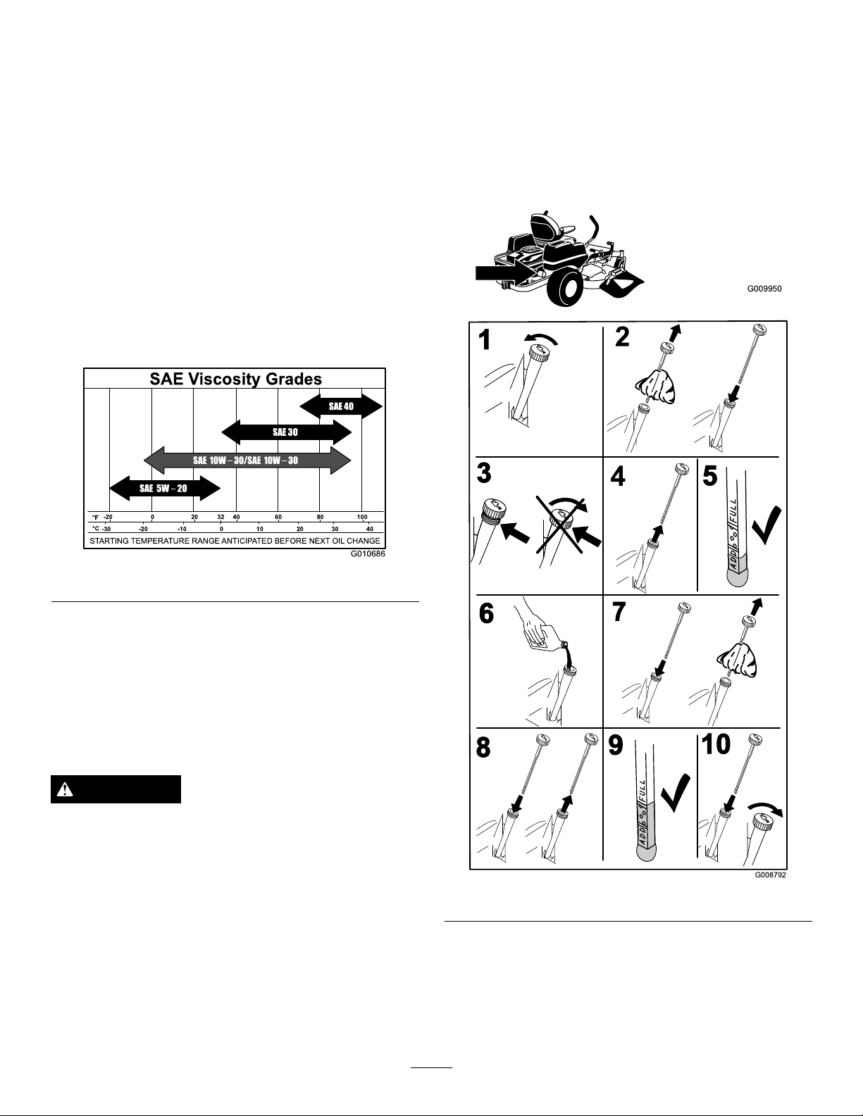
Viscosity:Seethetablebelow .
2.Makesuretheengineisstopped,level,andiscoolso
theoilhashadtimetodrainintothesump.
3.Tokeepdirt,grassclippings,etc.,outoftheengine,
cleantheareaaroundtheoilllcap/dipstickbefore
removingit.
4.Stoptheengine,removethekey,andwaitforall
movingpartstostopbeforeleavingtheoperating
position(
Figure31).
Note:Usingmultigradeoils(5W -20,10W -30,and10W
-40)willincreaseoilconsumption.Checkoillevelmore
frequentlywhenusingthem.
Figure30
CheckingtheEngineOilLevel
ServiceInterval:Beforeeachuseordaily
Note:Checktheoilwhentheengineiscold.
WARNING
Contactwithhotsurfacesmaycausepersonal
injury.
Keephands,feet,face,clothingandotherbody
partsawaythemuferandotherhotsurfaces.
Important:Donotoverllthecrankcasewithoil
becausedamagetotheenginemayresult.Donot
runenginewithoilbelowthelowmarkbecausethe
enginemaybedamaged.
1.Parkthemachineonalevelsurface,disengagethe
bladecontrolswitch,stoptheengine,engageparking
brake,andremovethekey .
Figure31
ChangingtheEngineOil
ServiceInterval:Aftertherst8hours—Changethe
engineoil.
27
Page 28
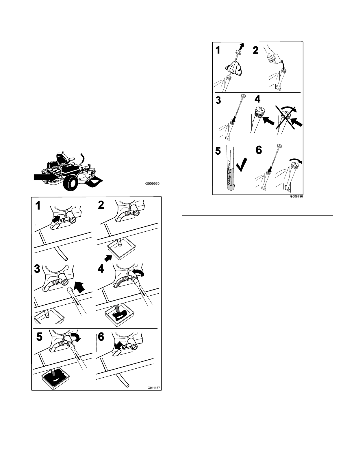
Every100hours—Changetheengine
G009950
G011157
1
2
3
4
5 6
G008796
2
3
4
5
6
1
oil.(moreoftenindusty,dirty
conditions)
Note:Disposeoftheusedoilatarecyclingcenter.
1.Starttheengineandletitrunveminutes.This
warmstheoilsoitdrainsbetter.
2.Parkthemachinesothatthedrainsideisslightly
lowerthantheoppositesidetoassuretheoildrains
completely.
3.DisengagethePTO,movethemotioncontrollevers
totheneutrallockedpositionandsettheparking
brake.
4.Stoptheengine,removethekey,andwaitforall
movingpartstostopbeforeleavingtheoperating
position(
Figure32).
5.Slowlypourapproximately80%ofthespeciedoil
intothellertubeandslowlyaddtheadditionaloil
tobringittotheFullmark(Figure33).
Figure33
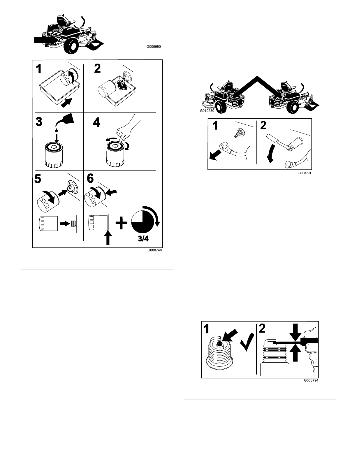
ChangingtheEngineOilFilter
ServiceInterval:Every200hours—Changetheoil
lter.(moreoftenindusty,dirty
conditions)
Note:Changetheengineoilltermorefrequently
whenoperatingconditionsareextremelydustyorsandy.
1.Draintheoilfromtheengine;refertoChangingthe
EngineOil.
2.Changetheengineoillter(
Figure34).
Figure32
28
Page 29
G009950
G008748
3/4
1
2
3
4
5
6
RemovingtheSparkPlug
G010230
G008794
1
2
1.DisengagethePTO,movethemotioncontrollevers
totheneutrallockedpositionandsettheparking
brake.
2.Stoptheengine,removethekey,andwaitforall
movingpartstostopbeforeleavingtheoperating
position.
Figure35
Figure34
Note:Ensuretheoilltergaskettouchestheengine
andthenanextra3/4turniscompleted.
3.Fillthecrankcasewiththepropertypeofnewoil;
refertoChangingtheOil.
ServicingtheSparkPlug
ServiceInterval:Every100hours—Checkthespark
plug(s).
Makesuretheairgapbetweenthecenterandside
electrodesiscorrectbeforeinstallingthesparkplug.
Useasparkplugwrenchforremovingandinstalling
thesparkplug(s)andagappingtool/feelergaugeto
checkandadjusttheairgap.Installanewsparkplug(s)
ifnecessary.
Note:Duetothedeeprecessaroundthespark
plug,blowingoutthecavitywithcompressedair
isusuallythemosteffectivemethodforcleaning.
Thesparkplugismostaccessiblewhentheblower
housingisremovedforcleaning.
CheckingtheSparkPlug
Important:Nevercleanthesparkplug(s).Always
replacethesparkplug(s)whenithas:ablack
coating,wornelectrodes,anoilylm,orcracks.
Ifyouseelightbrownorgrayontheinsulator,the
engineisoperatingproperly.Ablackcoatingonthe
insulatorusuallymeanstheaircleanerisdirty.
Setthegapto0.030inches(0.76mm).
Figure36
Type:NGKBPR4ES(orequivalent)
AirGap:0.030inch(0.76mm)
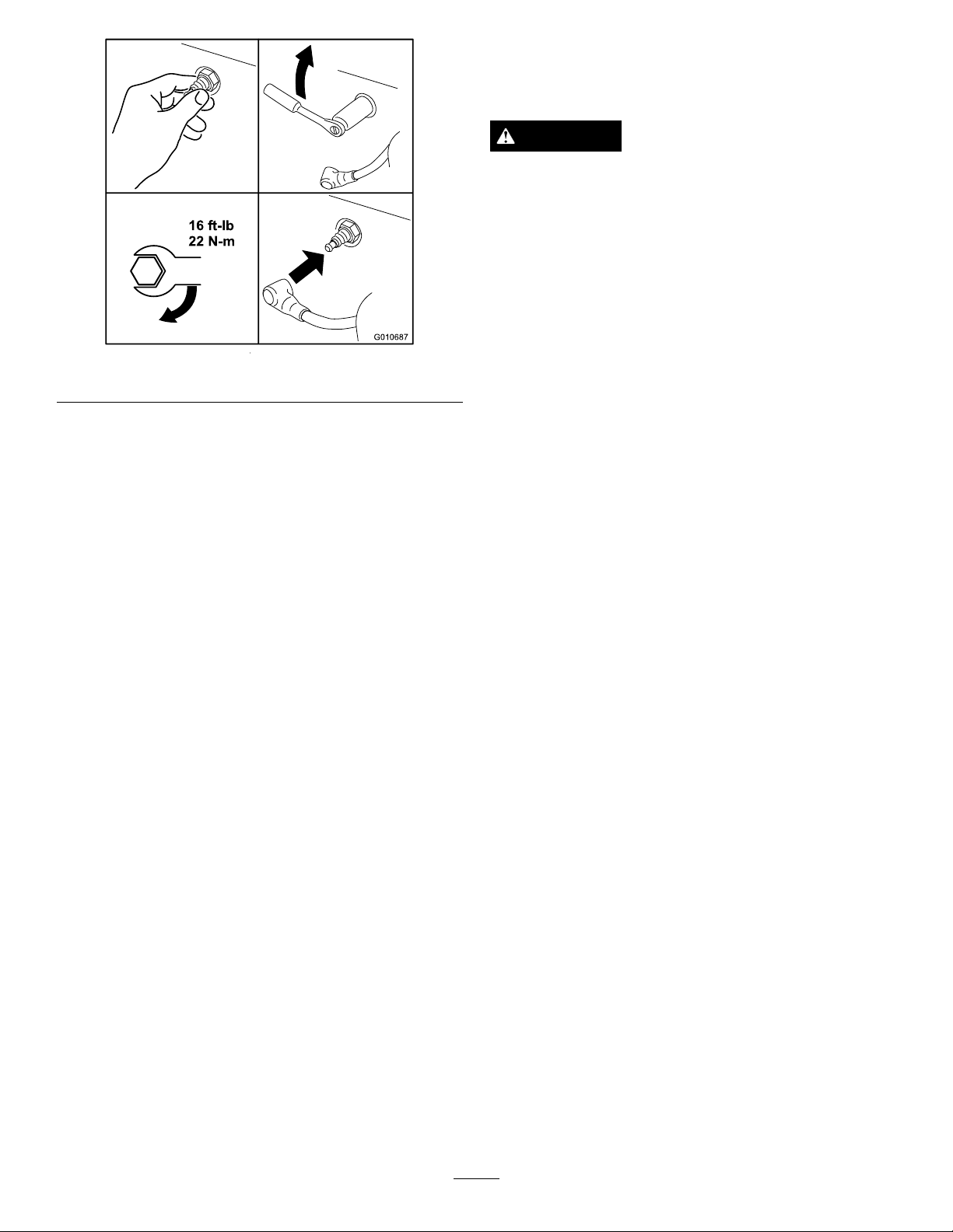
InstallingtheSparkPlug
Tightenthesparkplug(s)to16ft-lb(22N-m).
29
Page 30
16ft-lb
22N-m
G010687
Figure37
FuelSystem
Maintenance
DANGER
Incertainconditions,gasolineisextremely
ammableandhighlyexplosive.Areorexplosion
fromgasolinecanburnyouandothersandcan
damageproperty.
•Performanyfuelrelatedmaintenancewhenthe
engineiscold.Dothisoutdoorsinanopenarea.
Wipeupanygasolinethatspills.
•Neversmokewhendraininggasoline,andstay
awayfromanopenameorwhereasparkmay
ignitethegasolinefumes.
ReplacingtheFuelFilter
CleaningtheCoolingSystem
Cleantheairintakescreenfromgrassanddebrisbefore
eachuse.
1.Disengagethebladecontrolswitchandmovethe
controlleverstotheneutrallockedpositionand
applytheparkingbrake.
2.Stoptheengine,removethekey,andwaitforall
movingpartstostopbeforeleavingtheoperating
position.
3.Removetheairintakescreen,aircleanercover,and
fanhousing.
4.Cleandebrisandgrassfromtheparts.
5.Installtheairintakescreen,aircleanercover,and
fanhousing.
ServiceInterval:Every100hours—Replacethefuel
lter.
Neverinstalladirtylterifitisremovedfromthefuel
line.
1.Parkthemachineonalevelsurfaceanddisengage
thebladecontrolswitch.
2.Movethemotioncontrolleversoutwardtothe
parkposition,stoptheengine,removethekey,and
waitforallmovingpartstostopbeforeleavingthe
operatingposition.
3.Raisetheseatandlocatethefuellinecomingfrom
thefueltankbelow .Thefuellterisinthefuelline
betweenthetankandengine.
30
Page 31
G005071
212
3
4
6
5
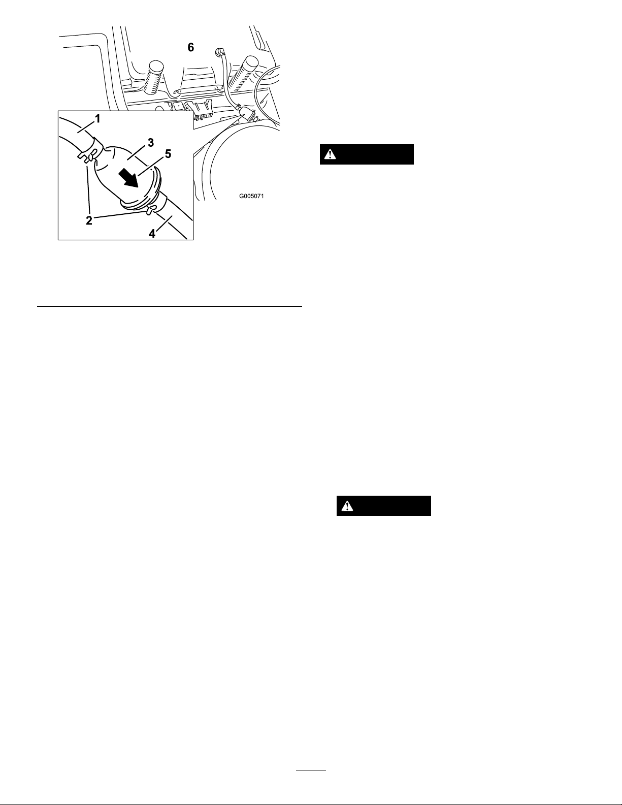
Figure38
1.Fuellinefromtank
2.Hoseclamp5.Flowdirectionarrow
3.Filter6.Fueltank
4.Fuellinetoengine
ElectricalSystem
Maintenance
ChargingtheBattery
RemovingtheBattery
WARNING
Batteryterminalsormetaltoolscouldshortagainst
metalmachinecomponentscausingsparks.Sparks
cancausethebatterygassestoexplode,resulting
inpersonalinjury.
•Whenremovingorinstallingthebattery,donot
allowthebatteryterminalstotouchanymetal
partsofthemachine.
•Donotallowmetaltoolstoshortbetween
thebatteryterminalsandmetalpartsofthe
machine.
4.Squeezetheendsofthehoseclampstogetherand
slidethemawayfromthelter(Figure38).
5.Removethelterfromthefuellines.
6.Installanewlterwiththeowdirectionarrow
comingfromthefueltankandpointingtothe
engine.Movethehoseclampsclosetothelter
Figure38)tosecureitinplace.
(
1.Parkthemachineonalevelsurfaceanddisengage
thebladecontrolswitch.
2.Movethemotioncontrolleversoutwardtothe
parkposition,stoptheengine,removethekey,and
waitforallmovingpartstostopbeforeleavingthe
operatingposition.
3.Removetheleftsideconsoletoaccessthebattery.
RefertheAccessingtheBatteryprocedureinthe
PremaintenanceProceduresforinstructions.
4.Disconnectthenegative(black)groundcablefrom
thebatterypost(
Figure39).Retainallfasteners.
WARNING
Incorrectbatterycableroutingcoulddamage
themachineandcablescausingsparks.Sparks
cancausethebatterygassestoexplode,
resultinginpersonalinjury.
•Alwaysdisconnectthenegative(black)
batterycablebeforedisconnectingthe
positive(red)cable.
•Alwaysconnectthepositive(red)battery
cablebeforeconnectingthenegative(black)
cable.
5.Slidetherubbercoverupthepositive(red)cable.
Disconnectthepositive(red)cablefromthebattery
31
post(Figure39).Retainallfasteners.
6.Removethebatteryhold-down(Figure39)andlift
thebatteryfromthebatterytray.
Page 32
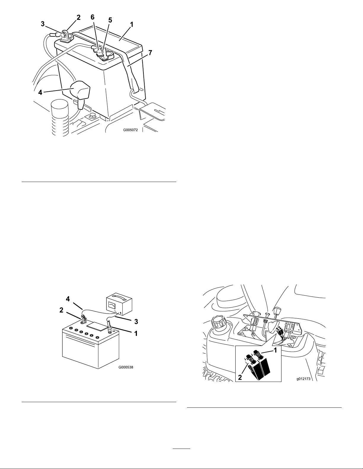
G005072
1
2
3
4
5
6
7
InstallingtheBattery
30
25
30
25
g012173
2
1
1.Positionthebatteryinthetraywiththeterminal
poststowardtheoperatingposition(
2.Installthepositive(red)batterycabletothepositive
(+)batteryterminalusingthefastenersremoved
previously.
3.Installthenegativebatterycabletothenegative
(-)batteryterminalusingthefastenersremoved
previously.
4.Slidetheredterminalbootontothepositive(red)
batterypost.
Figure39).
Figure39
1.Battery5.Negativebatterypost
2.Positivebatterypost6.Wingnut,washer,andbolt
3.Bolt,washer,andnut7.Batteryhold-down
4.Terminalboot
ChargingtheBattery
ServiceInterval:Beforestorage—Chargethebattery
anddisconnectbatterycables.
1.Removethebatteryfromthechassis;referto
RemovingtheBattery.
2.Chargethebatteryforaminimumof1hourat6to
10amps.Donotoverchargethebattery.
3.Whenthebatteryisfullycharged,unplugthecharger
fromtheelectricaloutlet,thendisconnectthe
chargerleadsfromthebatteryposts(
Figure40).
5.Securethebatterywiththehold-down(
Figure39).
6.Installtheleftsideconsole.RefertotheAccessing
theBatteryprocedureinPremaintenanceProcedures
forinstructions.
ServicingtheFuses
Theelectricalsystemisprotectedbyfuses.Itrequires
nomaintenance;however,ifafuseblows,checkthe
component/circuitforamalfunctionorshort.
Fuse:
•MainF1-30amp,blade-type
•ChargeCircuitF2-25amp,blade-type
1.Removethefourscrewssecuringthecontrolpanel
tothemachine.Retainallfasteners
2.Liftthecontrolpaneuptoaccessthemainwiring
harnessandfuseblock(
3.Toreplaceafuse,pulloutonthefusetoremoveit
Figure41).
(
Figure41).
1.Positivebatterypost
2.Negativebatterypost
Note:Donotrunthemachinewiththebattery
disconnected,electricaldamagemayoccur.
Figure40
3.Red(+)chargerlead
4.Black(-)chargerlead
1.Main-30amp
Figure41
2.Chargecircuit-25amp
4.Returnthecontrolpaneltoitsoriginalposition.Use
thefourscrewsremovedpreviouslytosecurethe
paneltothemachine.
32
Page 33
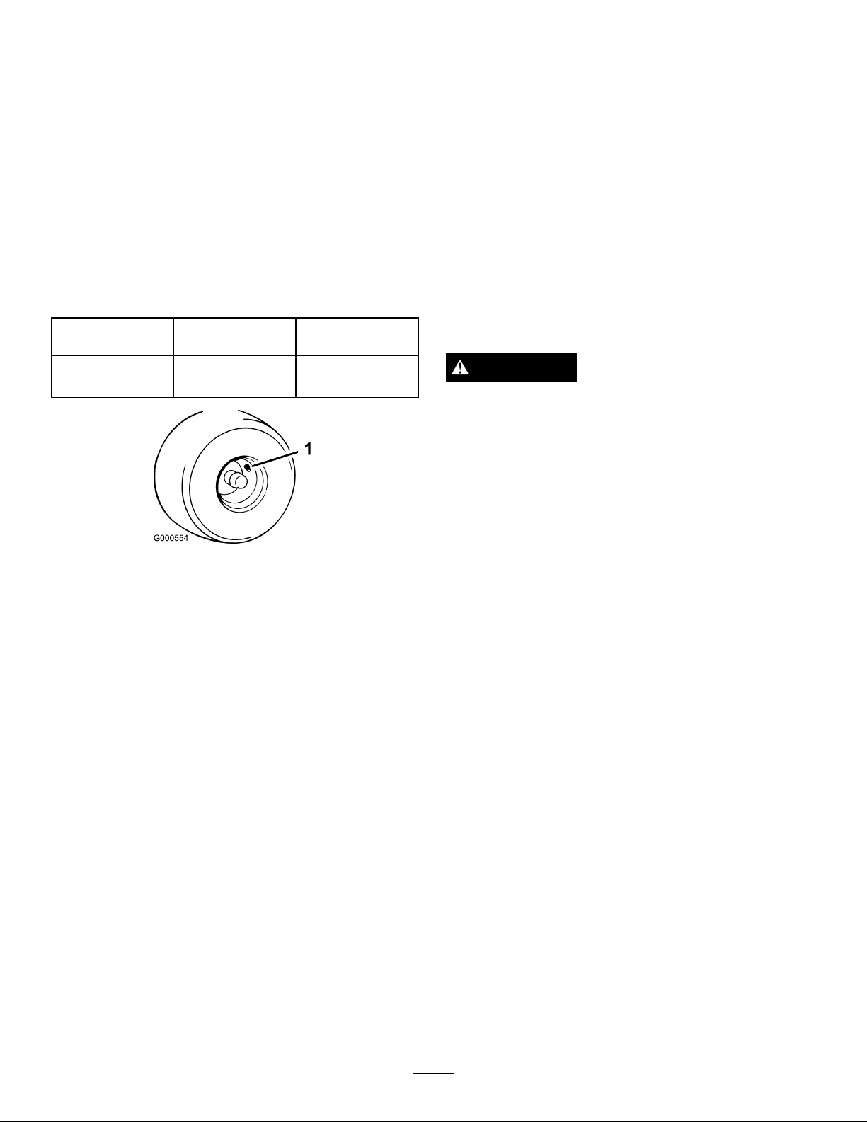
DriveSystem
MowerMaintenance
Maintenance
ServicingtheCuttingBlades
CheckingtheTirePressure
ServiceInterval:Every25hours—Checktirepressure.
Maintaintheairpressureinthefrontandreartiresas
specied.Uneventirepressurecancauseunevencut.
Checkthepressureatthevalvestem(Figure42).Check
thetireswhentheyarecoldtogetthemostaccurate
pressurereading.
TirePressures
ModelRearTire
74398
13psi(90kPa)50psi(344kPa)
FrontTire(caster
wheels)
Maintainsharpbladesthroughoutthecuttingseason
becausesharpbladescutcleanlywithouttearingor
shreddingthegrassblades.Tearingandshreddingturns
grassbrownattheedges,whichslowsgrowthand
increasesthechanceofdisease.
Checkthecutterbladesdailyforsharpness,andforany
wearordamage.Filedownanynicksandsharpenthe
bladesasnecessary.Ifabladeisdamagedorworn,
replaceitimmediatelywithagenuineTororeplacement
blade.Forconvenientsharpeningandreplacement,you
maywanttokeepextrabladesonhand.
WARNING
Awornordamagedbladecanbreak,andapiece
ofthebladecouldbethrownintotheoperator’s
orbystander’sarea,resultinginseriouspersonal
injuryordeath.
•Inspectthebladeperiodicallyforwearor
damage.
•Replaceawornordamagedblade.
1.Valvestem
Figure42
BeforeInspectingorServicingthe
Blades
Parkthemachineonalevelsurface,disengagetheblade
controlswitch,andmovethemotioncontrollevers
outwardtotheparkposition.Stoptheengineand
removethekey.
InspectingtheBlades
ServiceInterval:Beforeeachuseordaily—Checkthe
cuttingblades.
1.Inspectthecuttingedges(Figure43).Iftheedges
arenotsharporhavenicks,removeandsharpenthe
blades;refertoSharpeningtheBlades.
2.Inspecttheblades,especiallythecurvedarea
(Figure43).Ifyounoticeanydamage,wear,or
aslotforminginthisarea(item3inFigure43),
immediatelyinstallanewblade.
33
Page 34
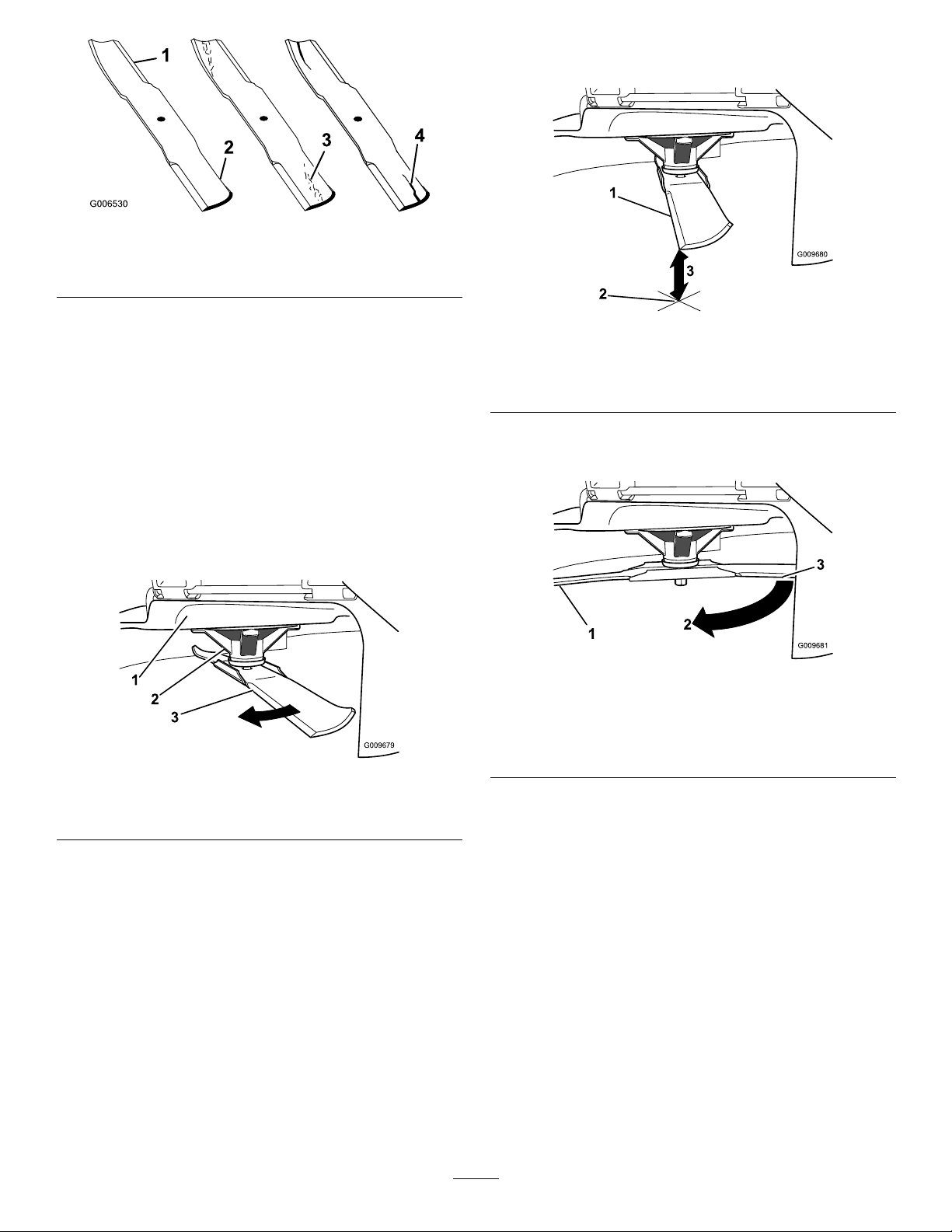
Figure43
G009679
1
2
3
G009680
1
2
3
G009681
1
2
3
1.Cuttingedge3.Wear/slotforming
2.Curvedarea
4.Damage
CheckingforBentBlades
Note:Themachinemustbeonalevelsurfaceforthe
followingprocedure.
3.Measurefromthetipofthebladetotheatsurface
here.
Figure45
1.Blade,inpositionformeasuring
2.Levelsurface
3.Measureddistancebetweenbladeandsurface(A)
1.Raisethemowerdecktothehighestheight-of-cut
position;alsoconsideredthe’transport’position.
2.Whilewearingthicklypaddedglovesorother
adequatehandprotectionslowlyrotatebladeto
bemeasureintoapositionthatallowseffective
measurementofthedistancebetweenthecutting
edgeandthelevelsurfacethemachineison.
Figure44
1.Deck3.Blade
2.Spindlehousing
4.Rotatethesameblade180degreessothatthe
opposingcuttingedgeisnowinthesameposition.
Figure46
1.Blade,sidepreviouslymeasured
2.Measurementpositionusedpreviously
3.Opposingsideofbladebeingmovedintomeasurement
position
5.Measurefromthetipofthebladetotheatsurface
here.Thevarianceshouldbenomorethan1/8inch
(3mm).
34
Page 35
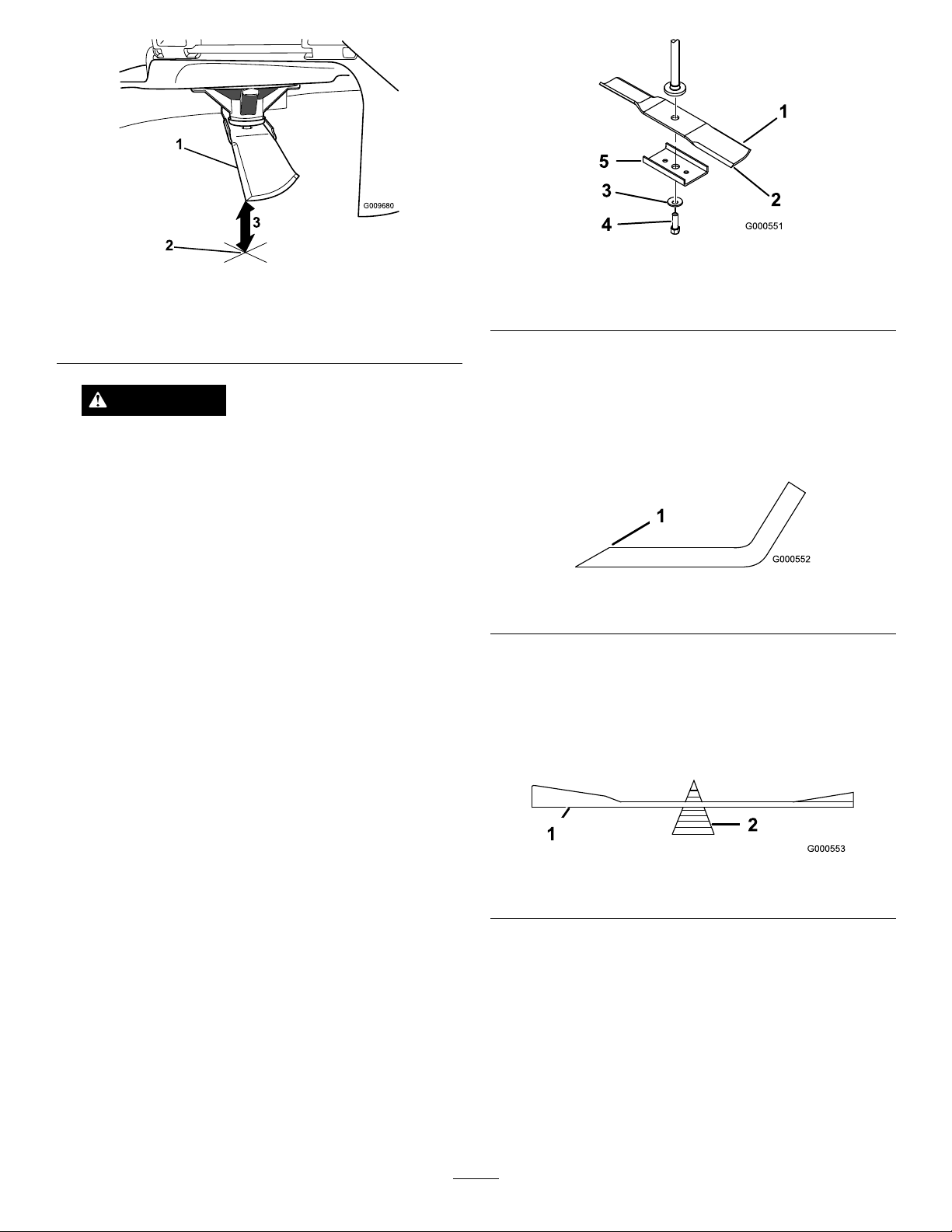
G009680
1
2
3
Figure47
1.Opposingbladeedge,inpositionformeasuring
2.Levelsurface
3.Secondmeasureddistancebetweenbladeandsurface(B)
1.Sailareaofblade
2.Blade
3.Curvedwasher
SharpeningtheBlades
Figure48
4.Bladebolt
5.Bladestiffener
WARNING
Abladethatisbentordamagedcouldbreak
apartandcouldseriouslyinjureorkillyouor
bystanders.
•Alwaysreplacebentordamagedbladewith
anewblade.
•Neverleorcreatesharpnotchesinthe
edgesorsurfacesofblade.
A.IfthedifferencebetweenAandBisgreater
than1/8inch(3mm)replacethebladewitha
newblade.RefertoRemovingtheBladesand
InstallingtheBlades.
Note:Ifabentbladeisreplacedwithanewone
andthedimensionobtainedcontinuestoexceed
1/8inch(3mm),thebladespindlecouldbebent.
ContactanAuthorizedToroDealerforservice.
B.Ifthevarianceiswithinconstraints,movetothe
nextblade..
1.Usealetosharpenthecuttingedgeatbothends
oftheblade(Figure49).Maintaintheoriginalangle.
Thebladeretainsitsbalanceifthesameamountof
materialisremovedfrombothcuttingedges.
Figure49
1.Sharpenatoriginalangle
2.Checkthebalanceofthebladebyputtingitona
bladebalancer(Figure50).Ifthebladestaysina
horizontalposition,thebladeisbalancedandcanbe
used.Ifthebladeisnotbalanced,lesomemetaloff
theendofthesailareaonly(
Figure49).Repeatthis
procedureuntilthebladeisbalanced.
Repeatthisprocedureoneachblade.
RemovingtheBlades
Thebladesmustbereplacedifasolidobjectishit,
ifthebladeisoutofbalance,orthebladeisbent.
Toensureoptimumperformanceandcontinued
safetyconformanceofthemachine,usegenuineToro
replacementblades.Replacementbladesmadebyother
manufacturersmayresultinnon-conformancewith
safetystandards.
Holdthebladeendusingaragorthickly-paddedglove.
Removethebladebolt,curvedwasher,bladestiffener,
andbladefromthespindleshaft(Figure48).
Figure50
1.Blade2.Balancer
InstallingtheBlades
1.Installthebladeontothespindleshaft(Figure48).
Important:Thecurvedpartoftheblademust
bepointingupwardtowardtheinsideofthe
mowertoensurepropercutting.
2.Installthebladestiffener,thecurvedwasher(cupped
sidetowardtheblade)andthebladebolt(
3.Torquethebladeboltto35-65ft-lb(47-88N-m).
35
Figure48).
Page 36
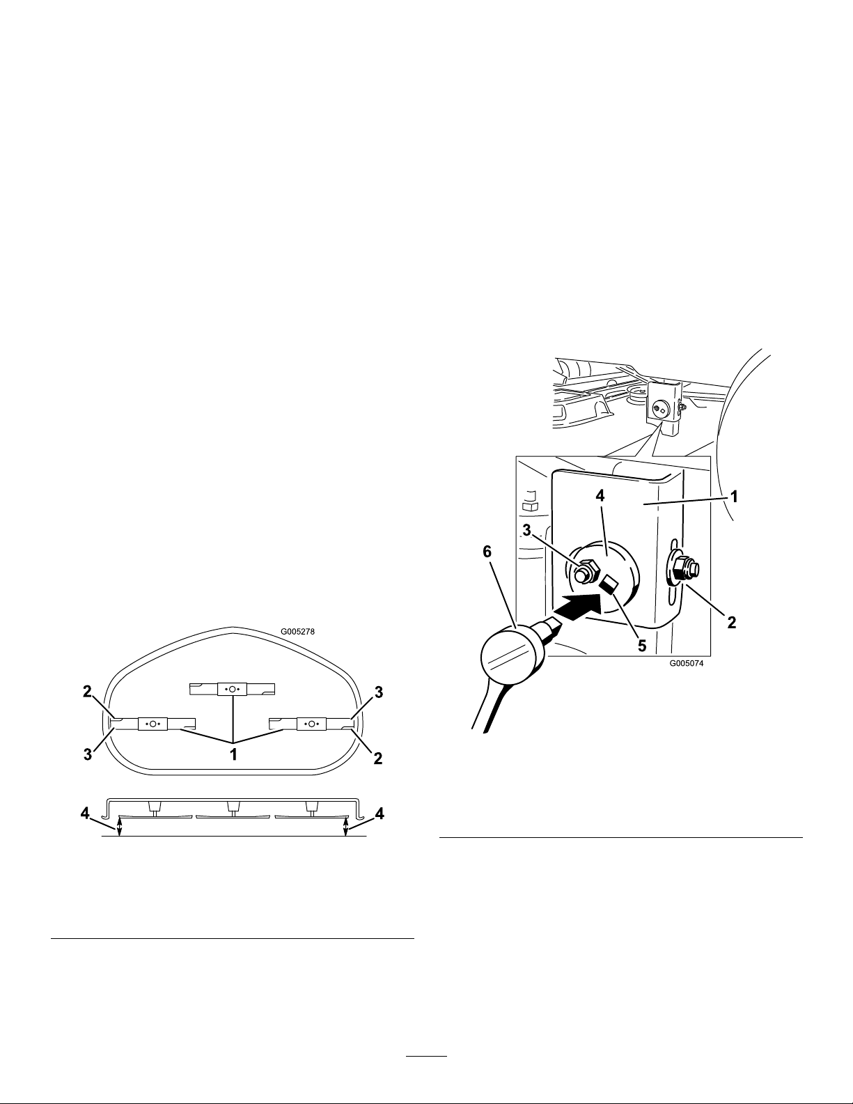
LevelingtheMowerDeck
G005278
1
2
2
3
3
4
4
3
G005074
1
2
3
4
5
6
Checktoensurethemowerdeckislevelanytimeyou
installthemowerorwhenyouseeanunevencuton
yourlawn.
Themowerdeckmustbecheckedforbentblades
priortoleveling;anybentbladesmustberemoved
andreplaced.RefertotheCheckingforBentBlades
procedurebeforecontinuing.
Themowerdeckmustbeleveledside-to-siderstthen
thefronttorearslopecanbeadjusted.
Requirements:
•Themachinemustbeonalevelsurface.
•Allfourtiremustbeproperlyinated.Referto
CheckingtheTirePressureintheDriveSystem
Maintenancesection.
Side-to-SideLeveling
1.Parkthemachineonalevelsurfaceanddisengage
thebladecontrolswitch.
6.Movetotheleftsideofthemachine.Loosen,but
donotremove,therearlockingnutonthehanger
bracket(
Figure52).
7.Loosenthesidelockingnutonthehangerbracket
justenoughtoallowtheeccentricplatetobeadjusted
Figure52).Usea3/8inchdriveextensionona
(
socketwrenchtomanipulatetheeccentricplate.Use
thewrenchtorepositiontheheightofthemower
deckandadjusttothedesiredheight.
8.Stopthedeckattheadjustedpositionandtightenthe
sidelockingnutonthehangerbrackettoholdthe
newposition(
Figure52).Tightentherearlocking
nutonthehangerbracket.
9.Continuelevelingthedeckbycheckingthe
front-to-rearbladeslope;refertoAdjustingthe
Front-to-RearBladeSlope.
2.Movethemotioncontrolleversoutwardtothe
parkposition,stoptheengine,removethekey,and
waitforallmovingpartstostopbeforeleavingthe
operatingposition.
3.Settheheight-of-cutlevertomiddleposition.
4.Carefullyrotatethebladessothattheyareallside
toside(
1.Bladessidetoside
2.Sailareaofblade4.Measurefromthetipofthe
Figure51).
Figure51
3.Outsidecuttingedges
bladetotheatsurface
here
Figure52
1.Hangerbracket4.Eccentricadjustmentplate
2.Rearlockingnut
3.Sidelockingnut6.Socketwrenchwith3/8
5.Socketwrenchhole
inchextension
AdjustingtheFront-to-RearBlade
Slope
Checkthefront-to-rearbladelevelanytimeyouinstall
themower.Ifthefrontofthemowerismorethan
5.Measurebetweentheoutsidecuttingedgesand
theatsurface(Figure51).Ifbothmeasurements
arenotwithin3/16inch(5mm),anadjustmentis
required;continuewiththisprocedure.
5/16inch(7.9mm)lowerthantherearofthemower,
adjustthebladelevelusingthefollowinginstructions:
1.Parkthemachineonalevelsurfaceanddisengage
thebladecontrolswitch.
36
Page 37
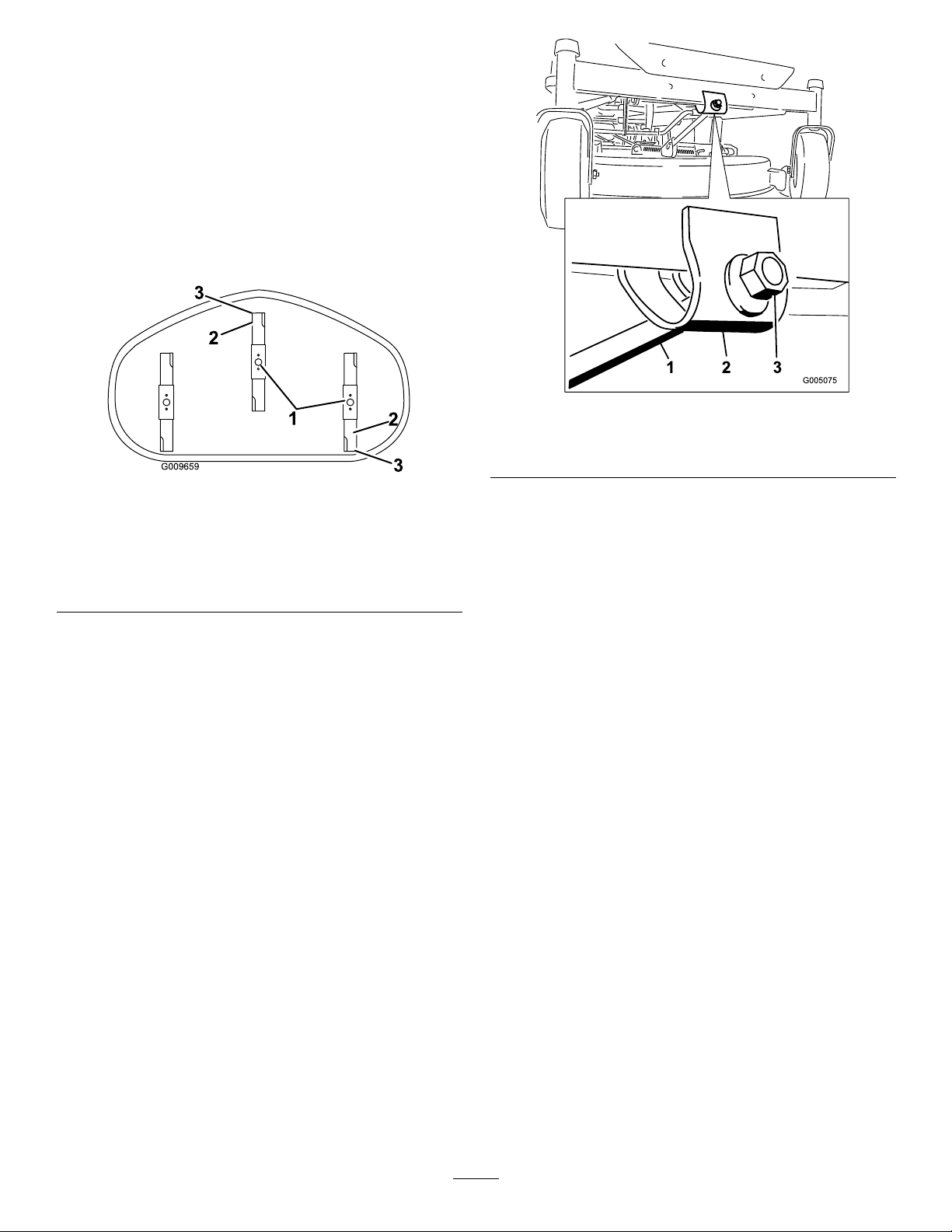
2.Movethemotioncontrolleversoutwardtothe
G009659
1
2
3
2
3
parkposition,stoptheengine,removethekey,and
waitforallmovingpartstostopbeforeleavingthe
operatingposition.
3.Settheheight-of-cutlevertomiddleposition.
Note:Checkandadjusttheside-to-sideblade
levelifyouhavenotcheckedthesetting;referto
Side-to-SideLeveling.
4.Carefullyrotatethebladessotheyarefacingfront
torear(
1.Bladesfronttorear3.Measurefromthetipofthe
2.Outsidecuttingedges
Figure53).
Figure53
MowerDeckswith3Blades
bladetotheatsurface
here
5.Measurefromthetipofthefrontbladetotheat
surfaceandthetipoftherearbladetotheat
surface(
Figure53).Ifthefrontbladetipisnot
1/16-5/16inch(1.6-7.9mm)lowerthantherear
bladetip,adjustthefrontlocknut.
Figure54
1.Adjustingrod3.Locknut
2.Adjustingblock
7.Toraisethefrontofthemower,tightenthe
adjustmentnut.Tolowerthefrontofthemower,
loosentheadjustmentnut.
8.Afteradjustment,checkthefront-to-rearslopeagain.
Continueadjustingthenutuntilthefrontbladetip
is1/16-5/16inch(1.6-7.9mm)lowerthantherear
bladetip(
Figure53).
9.Whenthefront-to-rearbladeslopeiscorrectcheck
theside-to-sidelevelofthemoweragain;referto
LevelingtheMowerfromSide-to-Side.
6.Toadjustthefront-to-rearbladeslope,rotatethe
adjustmentnutinthefrontofthemower(
Figure54).
RemovingtheMower
1.Parkthemachineonalevelsurfaceanddisengage
thebladecontrolswitch.
2.Movethemotioncontrolleversoutwardtothe
parkposition,stoptheengine,removethekey,and
waitforallmovingpartstostopbeforeleavingthe
operatingposition.
3.Lowertheheight-of-cutlevertothelowestposition.
4.Removethehairpincotterandclevispinfromthe
frontsupportrod(
frontofthemowerdecktotheground.
37
Figure55).Carefullylowerthe
Page 38
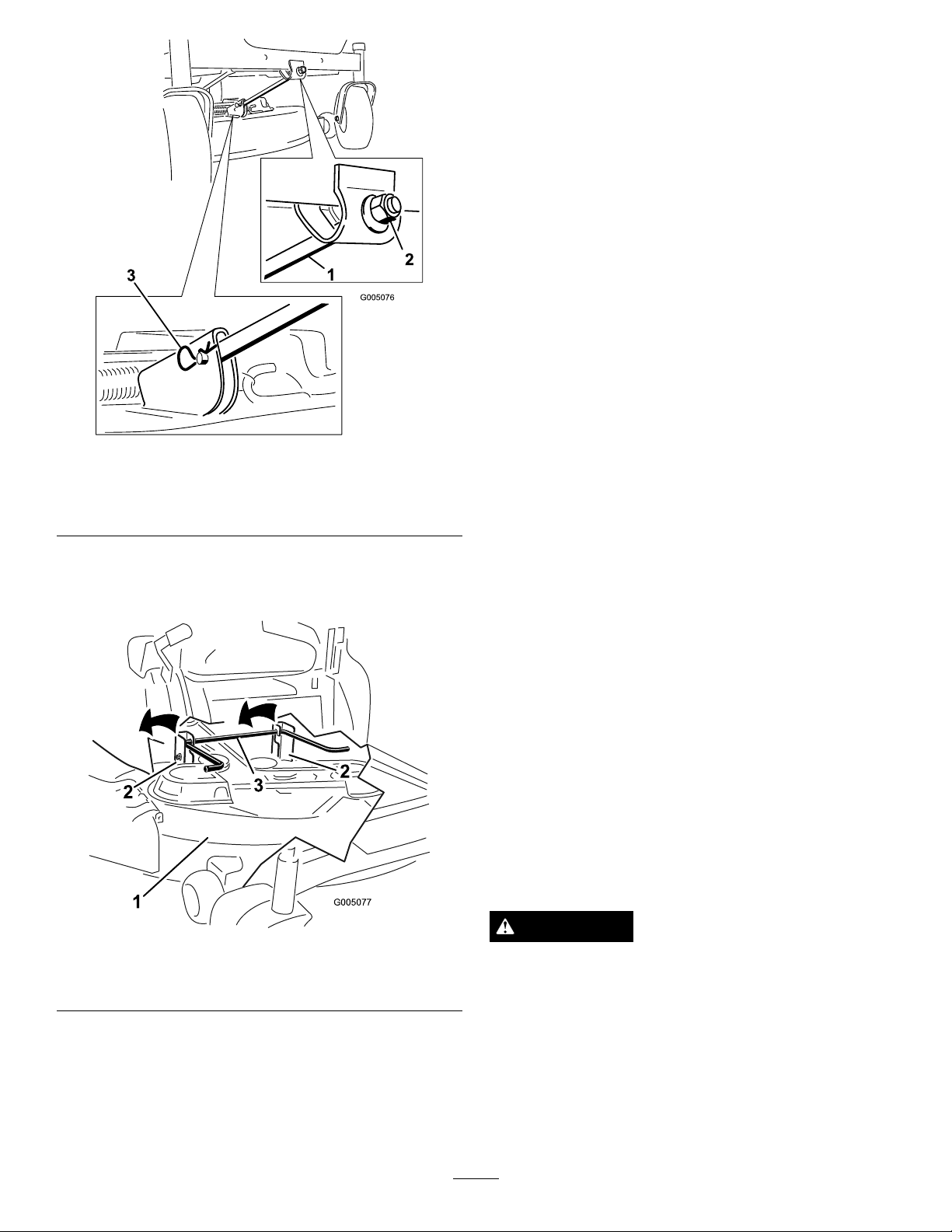
Figure55
2
2
3
G005077
1
2
2
3
1.Frontsupportrod3.Hairpincotterandclevis
2.Lockingnut
pin
5.Liftthemowerdeckandhangerbracketsclearof
therearliftrodandlowerthemowercarefullyto
theground(
Figure56).
MowerBeltMaintenance
InspectingtheBelts
ServiceInterval:Every25hours—Checkthebeltsfor
wear/cracks.
Checkthebeltsforcracks,frayededges,burnmarks,or
anyotherdamage.Replacedamagedbelts.
ReplacingtheMowerBelt
Squealingwhenthebeltisrotating,bladesslippingwhen
cuttinggrass,frayedbeltedges,burnmarksandcracks
aresignsofawornmowerbelt.ContactanAuthorized
ServiceDealertoreplacethemowerbeltifanyofthese
conditionsareevident.
InstallingtheMower
1.Parkthemachineonalevelsurfaceanddisengage
thebladecontrolswitch.
2.Movethemotioncontrolleversoutwardtothe
parkposition,stoptheengine,removethekey,and
waitforallmovingpartstostopbeforeleavingthe
operatingposition.
3.Slidethemowerunderthemachine.
Figure56
1.Mowerdeck
2.Hangerbracket
3.Rearliftrod
6.Slidethemowerdeckrearwardtoremovethemower
beltfromtheenginepulley .
7.Slidethemowerdeckoutfromunderneaththe
machine.
Note:Retainallpartsforfutureinstallation.
4.Lowertheheight-of-cutlevertothelowestposition.
5.Lifttherearofthemowerdeckandguidethehanger
bracketsovertherearliftrod(
Figure56).
6.Attachthefrontsupportrodtothemowerdeckwith
theclevispinandhairpincotter(Figure55).
7.Installthemowerbeltontotheenginepulley;refer
toReplacingtheMowerBelt.
ReplacingtheGrassDeector
ServiceInterval:Beforeeachuseordaily—Inspectthe
grassdeectorfordamage
WARNING
Anuncovereddischargeopeningcouldallowthe
lawnmowertothrowobjectsintheoperator’sor
bystander’sdirectionandresultinseriousinjury.
Also,contactwiththebladecouldoccur.
Neveroperatethemachinewithoutgrassdeector,
dischargecoverorgrasscollectionsysteminplace.
Inspectthegrassdeectorfordamagebeforeeachuse.
Replaceanydamagedpartsbeforeuse.
38
Page 39
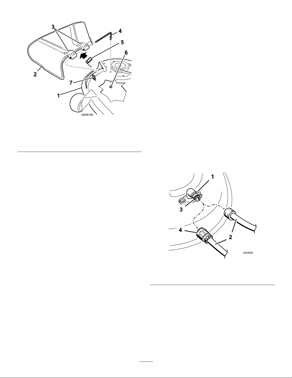
1.LocateitemsshowninFigure57.
G005192
1
2
3
4
5
6
7
Figure57
1.Mowerdeck
2.Grassdeector6.Nut(3/8inch)
3.Grassdeectorbracket7.Shortstand-off
4.Rod
5.Spring
2.Removethenut(3/8inch)fromtherodunderthe
mower(Figure57).
Cleaning
WashingtheUndersideofthe
Mower
ServiceInterval:Beforeeachuseordaily—Cleanthe
mowerhousing.
Washtheundersideofthemoweraftereachuseto
preventgrassbuildupforimprovedmulchactionand
clippingdispersal.
1.Parkthemachineonalevelsurfaceanddisengage
thebladecontrolswitch.
2.Movethemotioncontrolleversoutwardtothe
parkposition,stoptheengine,removethekey,and
waitforallmovingpartstostopbeforeleavingthe
operatingposition.
3.Attachthehosecouplingtotheendofthemower
washouttting,andturnthewateronhigh
Figure58).
(
Note:Spreadpetroleumjellyonthewashouttting
O-ringtomakethecouplingslideoneasierand
protecttheO-ring.
3.Slidetherodoutoftheshortstand-off,spring,and
grassdeector(
Figure57).Removethedamaged
orworngrassdeector.
4.Replacethegrassdeector(Figure57).
5.Sliderod,straightend,throughthereargrass
deectorbracket.
6.Placethespringontherod,withendwiresdown,
andbetweenthegrassdeectorbrackets.Sliderod
throughsecondgrassdeectorbracket(
7.Insertrodatfrontofgrassdeectorintoshort
stand-offondeck.Securerearendofrodintothe
mowerwithanut(3/8inch)(Figure57).
Important:Thegrassdeectormustbespring
loadedinthedownposition.Liftthedeector
uptotestthatitsnapstothefulldownposition.
Figure57).
Figure58
1.Washouttting3.O-ring
2.Hose
4.Coupling
4.Lowerthemowertothelowestheight-of-cut.
5.Sitontheseatandstarttheengine.Engagetheblade
controlswitchandletthemowerrunforoneto
threeminutes.
6.Disengagethebladecontrolswitch,stoptheengine,
andremovetheignitionkey .Waitforallmoving
partstostop.
7.Turnthewateroffandremovethecouplingfrom
thewashouttting.
39
Page 40

Note:Ifthemowerisnotcleanafteronewashing,
soakitandletitstandfor30minutes.Thenrepeat
theprocess.
8.Runthemoweragainforonetothreeminutesto
removeexcesswater.
WARNING
Abrokenormissingwashoutttingcould
exposeyouandotherstothrownobjectsorblade
contact.Contactwithbladeorthrowndebris
cancauseinjuryordeath.
•Replacebrokenormissingwashouttting
immediately,beforeusingmoweragain.
•Neverputyourhandsorfeetunderthe
mowerorthroughopeningsinthemower.
Storage
CleaningandStorage
1.Disengagethebladecontrolswitch,movethe
motioncontrolsoutwardtotheparkposition,stop
theengine,andremovethekey .
2.Removegrassclippings,dirt,andgrimefromthe
externalpartsoftheentiremachine,especiallythe
engine.Cleandirtandchafffromtheoutsideofthe
enginecylinderheadnsandblowerhousing.
Important:Youcanwashthemachinewith
milddetergentandwater.Donotpressure
washthemachine.Avoidexcessiveuseof
water,especiallynearthecontrolpanel,engine,
hydraulicpumps,andmotors.
3.Servicetheaircleaner;refertoServicingtheAir
CleanerintheEngineMaintenancesection.
4.Greaseandoilthemachine;refertotheLubrication
section.
5.Changethecrankcaseoilandlter;refertoServicing
theEngineOilintheEngineMaintenancesection.
6.Checkthetirepressure;refertoCheckingtheTire
PressureintheDriveSystemMaintenancesection.
7.Chargethebattery;refertoServicingtheBattery
intheElectricalSystemMaintenancesection.
8.Checktheconditionoftheblades;refertoServicing
theCuttingBladesintheMowerMaintenance
section.
9.Preparethemachineforstoragewhennon-use
occursover30days.Preparethemachineforstorage
asfollows.
10.Addapetroleumbasedstabilizer/conditionertothe
fuelinthetank.Followthemixinginstructionsfrom
thestabilizermanufacturer.Donotuseanalcohol
basedstabilizer(ethanolormethanol).
Note:Afuelstabilizer/conditionerismosteffective
whenmixedwithfreshgasolineandusedatalltimes.
Runtheenginetodistributetheconditionedfuel
throughthefuelsystem(5minutes).
Stoptheengine,allowittocool,anddrainthefuel
tank;refertoDrainingtheFuelTankintheFuel
SystemMaintenancesection.
Restarttheengineandrunituntilitstops.
Choketheengine.Startandruntheengineuntilit
willnotstart.
Disposeoffuelproperly.Recyclepursuanttolocal
codes.
40
Page 41

Important:Donotstorestabilizer/conditioned
gasolineover30days.
11.Removethesparkplug(s)andcheckitscondition;
refertoServicingtheSparkPlugintheEngine
Maintenancesection.Withthesparkplug(s)
removedfromtheengine,pourtwotablespoonsof
engineoilintothesparkplughole.Usethestarter
tocranktheengineanddistributetheoilinsidethe
cylinder.Installthesparkplug(s).Donotinstallthe
wireonthesparkplug(s).
12.Cleananydirtandchafffromthetopofthemower.
13.Scrapeanyheavybuildupofgrassanddirtfromthe
undersideofthemower,thenwashthemowerwith
agardenhose.
14.Checktheconditionofthedriveandmowerbelts.
15.Checkandtightenallbolts,nuts,andscrews.Repair
orreplaceanypartthatiswornordamaged.
16.Paintallscratchedorbaremetalsurfaces.Paintis
availablefromyourAuthorizedServiceDealer.
17.Storethemachineinaclean,drygarageorstorage
area.Removethekeyfromtheignitionswitchand
keepitinamemorableplace.Coverthemachineto
protectitandkeepitclean.
41
Page 42

Troubleshooting
Problem
Theengineoverheats.
Thestarterdoesnotcrank
Theenginewillnotstart,startshard,or
failstokeeprunning.
PossibleCauseCorrectiveAction
1.Theengineloadisexcessive.1.Reducegroundspeed.
2.Theoillevelinthecrankcaseislow.2.Addoiltothecrankcase.
3.Thecoolingnsandairpassages
undertheengineblowerhousingare
plugged.
4.Theaircleanerisdirty .
5.Dirt,water,orstalefuelisinfuel
system.
1.Thebladecontrolswitchisengaged.1.Movethebladecontrolswitchto
2.Themotioncontrolleversarenotinthe
parkposition.
3.Theoperatorisnotseated.
4.Thebatteryisdead.
5.Theelectricalconnectionsarecorroded
orloose.
6.Afuseisblown.6.Replacethefuse.
7.Arelayorswitchisdamaged.
1.Thefueltankisempty .1.Fillthefueltank.
2.Thechokeisnoton.
3.Theaircleanerisdirty .
4.Thesparkplugwire(s)islooseor
disconnected.
5.Thesparkplug(s)ispitted,fouled,or
thegapisincorrect.
6.Thereisdirtinfuellter.6.Replacethefuellter.
7.Dirt,water,orstalefuelisinfuel
system.
8.Thereisincorrectfuelinthefueltank.8.Drainthetankandreplacethefuelwith
9.Theoillevelinthecrankcaseislow.9.Addoiltothecrankcase.
3.Removetheobstructionfromthe
coolingnsandairpassages.
4.Cleanorreplacetheaircleaner
element.
5.ContactanAuthorizedServiceDealer
Disengaged.
2.Movethemotioncontrolleversoutward
totheparkposition.
3.Sitontheseat.
4.Chargethebattery.
5.Checktheelectricalconnectionsfor
goodcontact.
7.ContactanAuthorizedServiceDealer.
2.MovethechokelevertoOn.
3.Cleanorreplacetheaircleaner
element.
4.Installthewire(s)onthesparkplug.
5.Installanew,correctlygappedspark
plug(s).
7.ContactanAuthorizedServiceDealer.
thepropertype.
Theenginelosespower .
Themachinedoesnotdrive.
1.Theengineloadisexcessive.1.Reducegroundspeed.
2.Theaircleanerisdirty .
3.Theoillevelinthecrankcaseislow.3.Addoiltothecrankcase.
4.Thecoolingnsandairpassages
undertheengineblowerhousingare
plugged.
5.Thesparkplug(s)ispitted,fouled,or
thegapisincorrect.
6.Theventinthefuelcapisclosed.6.Opentheventinthefuelcap.
7.Thereisdirtinthefuellter.7.Replacethefuellter.
8.Dirt,water,orstalefuelisinthefuel
system.
9.Thereisincorrectfuelinthefueltank.9.Drainthetankandreplacethefuelwith
1.Thebypassvalvesareopen
2.Thetractionbeltsareworn,loose,or
broken.
3.Thetractionbeltsareoffofthepulleys.3.ContactanAuthorizedServiceDealer.
4.Thetransmissionhasfailed.4.ContactanAuthorizedServiceDealer.
2.Cleantheaircleanerelement.
4.Removetheobstructionfromthe
coolingnsandairpassages.
5.Installanew,correctlygappedspark
plug(s).
8.ContactanAuthorizedServiceDealer.
thepropertype.
1.Closethetowvalves.
2.ContactanAuthorizedServiceDealer.
42
Page 43

Problem
PossibleCauseCorrectiveAction
Thereisabnormalvibration.
Unevencuttingheight.
Thebladesdonotrotate.
1.Theenginemountingboltsareloose.1.Tightentheenginemountingbolts.
2.Theenginepulley,idlerpulley,orblade
pulleyisloose.
3.Theenginepulleyisdamaged.
4.Thecuttingblade(s)is/arebentor
unbalanced.
5.Ablademountingboltisloose.5.Tightentheblademountingbolt.
6.Abladespindleisbent.
1.Theblade(s)isnotsharp.1.Sharpentheblade(s).
2.Acuttingblade(s)is/arebent.2.Installanewcuttingblade(s).
3.Themowerisnotlevel.
4.Ananti-scalpwheelisnotsetcorrectly.4.Adjusttheanti-scalpwheelheight.
5.Theundersideofthemowerisdirty.5.Cleantheundersideofthemower.
6.Thetirepressureisincorrect.6.Adjustthetirepressure.
7.Abladespindleisbent.
1.Thedrivebeltisworn,looseorbroken.1.Installanewdrivebelt.
2.Thedrivebeltisoffofthepulley.
3.Themowerbeltisworn,loose,or
broken.
2.Tightentheappropriatepulley.
3.ContactanAuthorizedServiceDealer.
4.Installanewcuttingblade(s).
6.ContactanAuthorizedServiceDealer.
3.Levelthemowerfromside-to-sideand
front-to-rear.
7.ContactanAuthorizedServiceDealer.
2.Installthedrivebeltandcheckthe
adjustingshaftsandbeltguidesforthe
correctposition.
3.Installanewmowerbelt.
43
Page 44

Schematics
G009744
ElectricalDiagram(Rev.A)
44
Page 45

Notes:
45
Page 46

Notes:
46
Page 47

InternationalDistributorList
Distributor:
AtlantisSuveSulamaSisstemleriLt
BalamaPrimaEngineeringEquip.HongKong85221552163
B-RayCorporation
CascoSalesCompany
CeresS.A.CostaRica
CSSCTurfEquipment(pvt)Ltd.SriLanka
CyrilJohnston&Co.
EquiverMexico525553995444
FemcoS.A.Guatemala
G.Y .K.CompanyLtd.
GeomechanikiofAthensGreece
GuandongGoldenStarChina
HakoGroundandGardenSweden
HakoGroundandGarden
HayterLimited(U.K.)
HydroturfInt.CoDubai
HydroturfEgyptLLC
IbeaS.P .A.
IrriamcPortugal351212388260
IrrigationProductsInt’lPvtLtd.India862283960789
JeanHeybroekb.v .Netherlands31306394611
Lely(U.K.)Limited
MaquiverS.A.Colombia
MaruyamaMfg.Co.Inc.
MetraKft
Mountelda.s.CzechRepublic
MunditolS.A.
OslingerTurfEquipmentSA
OyHakoGroundandGardenAb
ParklandProductsLtd.NewZealand6433493760
Prochaska&Cie
RTCohen2004Ltd.
Riversa
RothMotorgerateGmBh&Co.Germany
ScSvendCarlsenA/S
SolvertS.A.S.
SpyprosStavrinidesLimitedCyprus
SurgeSystemsIndiaLimited
T-MarktLogisticsLtd.Hungary3626525500
ToroAustraliaAustralia61395807355
ToroEuropeBVBABelgium3214562960
Country:
Turkey902163448674
Korea82325512076
PuertoRico7877888383
NorthernIreland442890813121
Japan81726325861
Norway4722907760
UnitedKingdom441279723444
UnitedArabEmirates97143479479
Egypt2025194308
Italy390331853611
UnitedKingdom441480226800
Japan81332522285
Hungary3613263880
Argentina541148219999
Ecuador59342396970
Finland35898700733
Austria4312785100
Israel97298617979
Spain
Denmark4566109200
France33130817700
India911292299901
PhoneNumber:
5062391 138
94112746100
5024423277
30109350054
862087651338
4635100000
5712364079
420255704220
34952837500
4971442050
35722434131
374-0269RevA
Page 48

TheT oroWarranty
ConditionsandProductsCovered
TheToro®Companyanditsafliate,T oroWarrantyCompany ,pursuantto
anagreementbetweenthem,jointlypromisetorepairtheToroProduct
listedbelowifusedforresidentialpurposes*ifdefectiveinmaterialsor
workmanship.
Thefollowingtimeperiodsapplyfromthedateofpurchase:
ProductsWarrantyPeriod
WalkPowerMowers2yearlimitedwarranty
RearEngineRiders2yearlimitedwarranty
Lawn&GardenTractors
ElectricHandHeldProducts2yearlimitedwarranty
Snowthrowers
ConsumerZeroTurn
*OriginalPurchasermeansthepersonwhooriginallypurchasedtheT oro
Product
*Residentialpurposesmeansuseoftheproductonthesamelotasyour
home.Useatmorethanonelocation,orinstitutionalorrentaluse,is
consideredcommercialuse,andthecommercialusewarrantywould
apply.
2yearlimitedwarranty
2yearlimitedwarranty
2yearlimitedwarranty
LimitedWarrantyforCommercialUse
ToroConsumerProductsandattachmentsusedforcommercial,
institutional,orrentaluse,arewarrantedagainstdefectsinmaterials
orworkmanshipforthefollowingtimeperiodsfromthedateoforiginal
purchase:
ProductsWarrantyPeriod
WalkPowerMowers90daywarranty
RearEngineRiders90daywarranty
Lawn&GardenTractors
ElectricHandHeldProducts90daywarranty
Snowthrowers
ConsumerZeroTurn
90daywarranty
90daywarranty
45daywarranty
InstructionsforObtainingWarrantyService
IfyouthinkthatyourT oroProductcontainsadefectinmaterialsor
workmanship,followthisprocedure:
1.Contactyoursellertoarrangeserviceoftheproduct.Ifforanyreason
itisimpossibleforyoutocontactyourseller,youmaycontactany
ToroAuthorizedDistributortoarrangeservice.
2.Bringtheproductandyourproofofpurchase(salesreceipt)tothe
ServiceDealer.IfforanyreasonyouaredissatisedwiththeService
Dealer’sanalysisorwiththeassistanceprovided,contactusat:
CustomerCareDepartment,ConsumerDivision
TheT oroCompany
811 1LyndaleAvenueSouth
Bloomington,MN55420-1196
Manager:T echnicalProductSupport:001–952–887–8248
SeeattachedDistributorList
OwnerResponsibilities
YoumustmaintainyourT oroProductbyfollowingthemaintenance
proceduresdescribedintheOperator’sManual.Suchroutine
maintenance,whetherperformedbyadealerorbyyou,isatyourexpense.
ItemsandConditionsNotCovered
Thisexpresswarrantydoesnotcoverthefollowing:
•Costofregularmaintenanceserviceorwearparts,suchasrotor
blades(paddles),scraperblades,belts,fuel,lubricants,oilchanges,
sparkplugs,cable/linkageorbrakeadjustments
•Anyproductorpartwhichhasbeenalteredormisusedandrequires
replacementorrepairduetoaccidentsorlackofpropermaintenance
•Repairsnecessaryduetofailuretousefreshfuel(lessthanone
monthold),orfailuretoproperlypreparetheunitpriortoanyperiod
ofnon-useoveronemonth
•Engineandtransmission.Thesearecoveredbytheappropriate
manufacturer’sguaranteeswithseparatetermsandconditions
Allrepairscoveredbythesewarrantiesmustbeperformedbyan
AuthorizedToroServiceDealerusingToroapprovedreplacementparts.
GeneralConditions
Thepurchaseriscoveredbythenationallawsofeachcountry.Therights
towhichthepurchaserisentitledwiththesupportoftheselawsarenot
restrictedbythiswarranty.
374-0268RevA
 Loading...