

Page 1

FormNo.3381-503RevB
TimeCutter
®
ZS5000TFRiding
Mower
ModelNo.74395—SerialNo.314000001andUp
Registeratwww.T oro.com.
OriginalInstructions(EN)
*3381-503*B
Page 2
Thismachineisaride-on,rotary-bladelawnmowerintended
G014523
1
tobeusedbyhomeownersinresidentialapplications.Itis
primarilydesignedforcuttinggrassonwell-maintainedlawns.
Itisnotdesignedforcuttingbrush,mowinggrassandother
growthalongsidehighways,orforagriculturaluses.
WARNING
CALIFORNIA
Proposition65Warning
Thisproductcontainsachemicalorchemicals
knowntotheStateofCaliforniatocausecancer,
birthdefects,orotherreproductiveharm.
Theengineexhaustfromthisproduct
containschemicalsknowntotheStateof
Californiatocausecancer,birthdefects,
orotherreproductiveharm.
Important:Thisengineisnotequippedwithaspark
arrestermufer.ItisaviolationofCaliforniaPublic
ResourceCodeSection4442touseoroperatetheengine
onanyforest-covered,brush-covered,orgrass-covered
land.Otherstatesorfederalareasmayhavesimilarlaws.
Introduction
Readthisinformationcarefullytolearnhowtooperateand
maintainyourproductproperlyandtoavoidinjuryand
productdamage.Youareresponsibleforoperatingthe
productproperlyandsafely.
YoumaycontactTorodirectlyatwww .Toro.comforproduct
andaccessoryinformation,helpndingadealer,ortoregister
yourproduct.
Wheneveryouneedservice,genuineT oroparts,oradditional
information,contactanAuthorizedServiceDealerorToro
CustomerServiceandhavethemodelandserialnumbersof
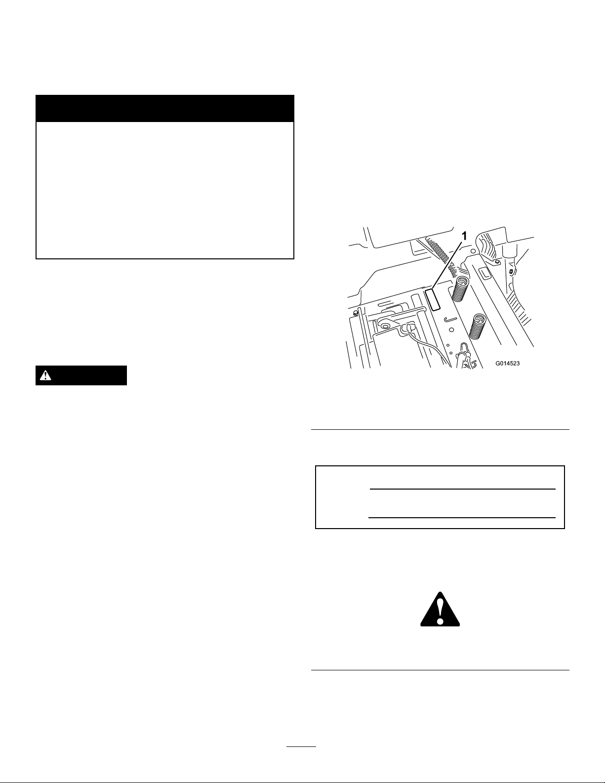
yourproductready.Figure1identiesthelocationofthe
modelandserialnumbersontheproduct.Writethenumbers
inthespaceprovided.
ThissparkignitionsystemcomplieswithCanadianICES-002.
WARNING
Removingstandardoriginalequipmentpartsand
accessoriesmayalterthewarranty,traction,and
safetyofthemachine.FailuretouseoriginalToro
partscouldcauseseriousinjuryordeath.Making
unauthorizedchangestotheengine,fuelorventing
system,mayviolateEPAandCARBregulations.
Replaceallpartsincluding,butnotlimitedto,tires,
belts,blades,andfuelsystemcomponentswith
originalToroparts.
Theenclosed
informationregardingtheUSEnvironmentalProtection
Agency(EPA)andtheCaliforniaEmissionControl
Regulationofemissionsystems,maintenance,and
warranty.Replacementsmaybeorderedthroughthe
enginemanufacturer.
Formodelswithstatedenginehorsepower,thegross
horsepoweroftheenginewaslaboratorytestedbytheengine
manufacturerinaccordancewithSAEJ1995andratedto
J2723.
Engine Owner's Man ual
issuppliedfor
Figure1
Undertheseat
1.Modelandserialnumberplate
Writetheproductmodelandserialnumbersinthespace
below:
ModelNo.
SerialNo.
Thismanualidentiespotentialhazardsandhassafety
messagesidentiedbythesafetyalertsymbol(Figure2),
whichsignalsahazardthatmaycauseseriousinjuryordeath
ifyoudonotfollowtherecommendedprecautions.
Figure2
1.Safetyalertsymbol.
©2014—TheToro®Company
8111LyndaleAvenueSouth
Bloomington,MN55420
Thismanualuses2wordstohighlightinformation.
Importantcallsattentiontospecialmechanicalinformation
andNoteemphasizesgeneralinformationworthyofspecial
attention.
Contactusatwww.Toro.com.
2
PrintedintheUSA.
AllRightsReserved
Page 3

Contents
Introduction..................................................................2
Safety...........................................................................4
SafeOperatingPractices...........................................4
ToroRidingMowerSafety........................................6
SlopeIndicator.......................................................7
SafetyandInstructionalDecals.................................8
ProductOverview.........................................................12
Controls...............................................................12
Operation....................................................................14
AddingFuel...........................................................14
CheckingtheEngine-oilLevel..................................15
BreakingInaNewMachine.....................................15
ThinkSafetyFirst...................................................15
StartingtheEngine.................................................16
OperatingtheBlades...............................................17
TestingtheSafety-interlockSystem...........................18
StoppingtheEngine...............................................18
Driving.................................................................19
StoppingtheMachine.............................................20
AdjustingtheHeight-of-Cut....................................21
AdjustingtheAnti-scalpRollers................................21
PositioningtheSeat................................................21
AdjustingtheMotion-controlLevers.........................22
PushingtheMachinebyHand..................................22
ConvertingtoSide-dischargeMode...........................23
OperatingTips......................................................25
Maintenance.................................................................26
RecommendedMaintenanceSchedule(s)......................26
PremaintenanceProcedures........................................27
RaisingtheSeat......................................................27
Lubrication...............................................................27
GreasingtheBearings.............................................27
EngineMaintenance..................................................28
ServicingtheAirCleaner.........................................28
ServicingtheEngineOil..........................................28
ServicingtheSparkPlug..........................................30
CleaningtheCoolingSystem....................................31
FuelSystemMaintenance...........................................32
ReplacingtheIn-lineFuelFilter................................32
ElectricalSystemMaintenance....................................33
ChargingtheBattery...............................................33
ServicingtheFuses.................................................34
DriveSystemMaintenance.........................................35
CheckingtheTirePressure......................................35
ReleasingtheElectricBrake.....................................35
HydraulicSystemMaintenance....................................36
CheckingtheHydraulicOilLevel..............................36
ChangingtheHydraulic-systemOiland
Filters................................................................36
MowerMaintenance...................................................39
ServicingtheCuttingBlades.....................................39
LevelingtheMowerDeck........................................41
RemovingtheMower..............................................43
InstallingtheMower...............................................44
ReplacingtheGrassDeector..................................44
MowerBeltMaintenance............................................46
InspectingtheBelts................................................46
ReplacingtheMowerBelt........................................46
Cleaning...................................................................47
WashingtheUndersideoftheMower........................47
Storage........................................................................48
CleaningandStorage..............................................48
Troubleshooting...........................................................49
Schematics...................................................................51
3
Page 4

Safety
Improperuseormaintenancebytheoperatororowner
canresultininjury.Toreducethepotentialforinjury,
complywiththesesafetyinstructions,andpayattentionto
thesafetyalertsymbol,whichmeansCaution,Warning,or
Danger—“personalsafetyinstruction.”Failuretocomply
withtheinstructionsmayresultinpersonalinjuryor
death.
Important:Thismachinewasmanufacturedaccording
totheappropriateregulatorystandardsineffectatthe
timeofmanufacture.Modifyingthismachineinany
waymaycauseittobeoutofcompliancewiththose
standardsandwiththeinstructionsinthisOperator’s
Manual.Modicationstothismachineshouldonlybe
madebyeitherthemanufactureroranAuthorizedToro
Dealer.
Thisproductiscapableofamputatinghandsandfeet.Follow
allsafetyinstructionstoavoidseriousinjuryordeath.
Theowner/usercanpreventandisresponsibleforaccidents
orinjuriesoccurringtopeople,ordamagetoproperty.
Important:Theadditionofattachmentsmadeby
othermanufacturersthatdonotmeetAmerican
NationalStandardsInstitutecerticationwillcause
noncomplianceofthismachine.
SafeOperatingPractices
Thisproductiscapableofamputatinghandsandfeetand
throwingobjects.Alwaysfollowallsafetyinstructionsto
avoidseriousinjuryordeath.
ThefollowinginstructionsareadaptedfromANSIstandard
B71.1-2012.AllthelanguagewithinthisANSIstandard
appliestothismachine;however,duetotheapplicationof
thestandardacrossmanydifferenttypesofproductssome
statementscanseemgeneralormisleading.Intheseinstances,
Torohasrenedthestatementtoconveythemeaningofthe
standardwhilebettermatchingtheproductthisOperator's
Manualpertains.Safetyinformationinadditiontothe
instructionsfoundintheANSIstandardbelowcanbefound
inToroRidingMowerSafetyattheendofthissection.
•Nevercarrypassengers.
•Donotmowinreverseunlessabsolutelynecessary.
Alwayslookdownandbehindbeforeandwhilebacking
up.
•Beawareofthemowerdischargedirectionanddonot
pointitatanyone.Avoiddischargingmaterialagainsta
wallorobstruction.Materialmayricochetbacktoward
theoperator.Stoptheblade(s)whencrossinggravel
surfaces.
•Donotoperatethemachinewithoutdeector,discharge
coverorentiregrasscollectionsysteminplaceand
working.
•Bealert,slowdownandusecautionwhenmakingturns.
Lookbehindandtothesidebeforechangingdirections.
•Neverleavearunningmachineunattended.Alwaysturn
offblades,setparkingbrake,stopengine,andremovekey
beforedismounting.
•Turnoffbladeswhennotmowing.Stoptheengine,wait
forallpartstocometoacompletestopandremovethe
keybeforecleaningthemachine,removingthegrass
catcheroruncloggingthedischargechute.
•Operatethemachineonlyindaylightorgoodarticial
light.
•Donotoperatethemachinewhileundertheinuence
ofalcoholordrugs.
•Watchfortrafcwhenoperatingnearorcrossing
roadways.
•Useextracarewhenloadingorunloadingthemachine
intoatrailerortruck.
•Alwaysweareyeprotectionwhenoperatingthemower.
•Dataindicatesthatoperators,age60yearsandabove,are
involvedinalargepercentageofridingmower-related
injuries.Operatorsshouldevaluatetheirabilitytooperate
theridingmowersafelyenoughtoprotectthemselvesand
othersfromseriousinjury.
•Alwaysfollowtherecommendationsforanyapplication
ofcounterweights.
•Lightningcancausesevereinjuryordeath.Iflightning
isseenorthunderisheardinthearea,donotoperate
themachine;seekshelter.
GeneralOperation
•Read,understand,andfollowallinstructionsinthe
operator'smanualandonthemachinebeforestarting.
•Donotplacehandsorfeetnearrotatingpartsorunder
themachine.Keepclearofthedischargeopeningatall
times.
•Allowonlyresponsibleadultswhoarefamiliarwiththe
instructionstooperatethemachine.
•Cleartheareaofobjectssuchasrocks,toys,wire,etc.,
whichcouldbepickedupandthrownbytheblade.
•Besuretheareaisclearofotherpeoplebeforemowing.
Stopthemachineifanyoneentersthearea.
SlopeOperation
Slopesareamajorfactorrelatedtolossofcontroland
tip-overaccidents,whichcanresultinsevereinjuryordeath.
Operationonallslopesrequiresextracaution.Ifyoucannot
backuptheslopeorifyoufeeluneasyonit,donotmowit.
•Donotmowslopesgreaterthan15degrees.
•Watchforditches,holes,rocks,dips,andrisesthatchange
theoperatingangle,asroughterraincouldoverturnthe
machine.
•Choosealowgroundspeedsoyouwillnothavetostop
whileoperatingonaslope.
4
Page 5

•Donotmowslopeswhengrassiswet.Slippery
conditionsreducetractionandcouldcauseslidingand
lossofcontrol.
•Alwayskeepthedrivewheelsengagedwhengoingdown
slopes.
•Reducespeedanduseextremecautiononslopes.
•Donotmakesuddenturnsorrapidspeedchanges.
•Removeormarkobstaclessuchasrocks,treelimbs,etc.
fromthemowingarea.Tallgrasscanhideobstacles.
•Avoidsuddenstartswhenmowinguphillbecausethe
mowermaytipbackwards.
•Beawarethatlossoftractionmayoccurgoingdownhill.
Weighttransfertothefrontwheelsmaycausedrive
wheelstoslipandcauselossofbrakingandsteering.
•Alwaysavoidsuddenstartingorstoppingonaslope.If
tireslosetraction,stopthemachine,disengagetheblades
andproceedslowlyofftheslope.
•Useextremecarewithgrasscatchersorotherattachments.
Thesecanchangethestabilityofthemachineandcause
lossofcontrol.
•Donottrytostabilizethemachinebyputtingyourfoot
ontheground.
•Donotmowneardrop-offs,ditches,steepbanksor
water.Wheelsdroppingoveredgescancauserollovers,
whichmayresultinseriousinjury,deathordrowning.
•Useawalkbehindmowerand/orahandtrimmernear
drop-offs,ditches,steepbanksorwater.
Children
Tragicaccidentscanoccuriftheoperatorisnotalerttothe
presenceofchildren.Childrenareoftenattractedtothe
machineandthemowingactivity.Neverassumethatchildren
willremainwhereyoulastsawthem.
•Keepchildrenoutofthemowingareaandunderthe
watchfulcareofanotherresponsibleadult,notthe
operator.
•Bealertandturnthemachineoffifchildrenenterthe
area.
•Beforeandwhilebackingorchangingdirection,look
behind,down,andside-to-sideforsmallchildren.
•Nevercarrychildren,evenwiththebladesoff.Theymay
falloffandbeseriouslyinjuredorinterferewithsafe
machineoperation.
•Childrenwhohavebeengivenridesinthepastmay
suddenlyappearinthemowingareaforanotherrideand
berunoverorbackedoverbythemower.
•Neverallowchildrentooperatethemachine.
•Useextracarewhenapproachingblindcorners,shrubs,
trees,theendofafenceorotherobjectsthatmayobscure
vision.
TowingSafety
•Donotattachtowedequipmentexceptatthehitchpoint.
•Followtheattachmentmanufacturer'srecommendation
forweightlimitsfortowedequipmentandtowingon
slopes.Towedweightmustnotexceedtheweightofthe
machine,operator,andballast.Usecounterweightsor
wheelweightsasdescribedintheattachment,orinthe
pullingmachineOperator’sManual.
•Neverallowchildrenorothersinorontowedequipment.
•Onslopes,theweightofthetowedequipmentmaycause
lossoftraction,increasedriskofrollover,andlossof
control.Reducethetowedweightandslowdown.
•Stoppingdistanceincreaseswiththeweightofthetowed
load.Travelslowlyandallowextradistancetostop.
•Makewideturnstokeeptheattachmentclearofthe
machine.
Service
SafeHandlingofGasoline:
Toavoidpersonalinjuryorpropertydamage,useextracare
whenhandlinggasolineandotherfuels.Theyareammable
andthevaporsareexplosive.
•Extinguishallcigarettes,cigars,pipesandothersources
ofignition.
•Useonlyanapprovedcontainer.
•Neverremovethegascaporaddfuelwhentheengineis
running.Allowtheenginetocoolbeforerefueling.
•Neverrefuelthemachineindoors.
•Neverstorethemachineorfuelcontainerinsidewhere
thereisanopename,suchasnearawaterheateror
furnace.
•Neverllcontainersinsideavehicleoronatruckor
trailerwithaplasticliner.Alwaysplacecontainersonthe
groundawayfromyourvehiclebeforelling.
•Removegas-poweredequipmentfromthetruckortrailer
andrefuelitontheground.Ifthisisnotpossible,then
refuelsuchequipmentwithaportablecontainer,rather
thanfromagasolinedispensernozzle.
•Keepthenozzleincontactwiththerimofthefueltank
orcontaineropeningatalltimesuntilthefuelingis
complete.Donotuseanozzlelock-opendevice.
•Iffuelisspilledonclothing,changeclothingimmediately.
•Neveroverllthefueltank.Replacegascapandtighten
securely.
GeneralService:
•Neveroperateamachineinsideaclosedarea.Engine
exhaustcontainscarbonmonoxide,whichisanodorless,
deadlypoisonthatcankillyou.
•Keepnutsandboltstight,especiallythebladeattachment
bolts.Keepequipmentingoodcondition.
5
Page 6

•Neverinterferewiththeintendedfunctionofasafety
deviceortoreducetheprotectionprovidedbyasafety
device.Checktheirproperoperationregularly.
•Keepthemachinefreeofgrass,leaves,orotherdebris
build-up.Cleanupoilorfuelspillagefuelsoakeddebris.
Allowthemachinetocoolbeforestoring.
•Stopandinspecttheequipmentifyoustrikeanobject.
Repair,ifnecessary,beforerestarting.
•Nevermakeanyadjustmentsorrepairswiththeengine
running.
•Grasscatchercomponentsaresubjecttowear,damage
anddeterioration,whichcouldexposemovingpartsor
allowobjectstobethrown.Frequentlycheckcomponents
andreplacewithmanufacturers'recommendedparts,
whennecessary.
•Mowerbladesaresharpandcancut.Wraptheblade(s)or
weargloves,anduseextracautionwhenservicingthem.
•Checkforproperbrakeoperationfrequently .Adjustand
serviceasrequired.
•Maintainorreplacesafetyandinstructiondecalsas
necessary.
•UseonlygenuineTororeplacementpartstoensurethat
originalstandardsaremaintained.
ToroRidingMowerSafety
ThefollowinglistcontainssafetyinformationspecictoToro
productsorothersafetyinformationthatyoumustknowthat
maynotbeincludedintheANSIstandards.
•Stoptheengine,movethemotioncontrolleverstoneutral
andoutwardtotheparkposition,disengagetheblade
controlswitch,removekeybeforeanddisconnectspark
plugwire(s)performinganyservice,repairs,maintenance
oradjustments.
•Keephands,feet,hair,andlooseclothingawayfrom
attachmentdischargearea,undersideofmowerandany
movingpartswhileengineisrunning.
•Donottouchequipmentorattachmentpartswhichmay
behotfromoperation.Allowtocoolbeforeattempting
tomaintain,adjustorservice.
•Batteryacidispoisonousandcancauseburns.Avoid
contactwithskin,eyes,andclothing.Protectyourface,
eyes,andclothingwhenworkingwithabattery.
•Batterygasescanexplode.Keepcigarettes,sparksand
amesawayfrombattery.
•UseonlyToroapprovedattachments.Warrantymaybe
voidedifusedwithunapprovedattachments.
•Ifloadingthemachineontoatrailerortruck,useasingle,
full-widthramponly.Therampangleshouldnotexceed
15degrees.
6
Page 7
SlopeIndicator
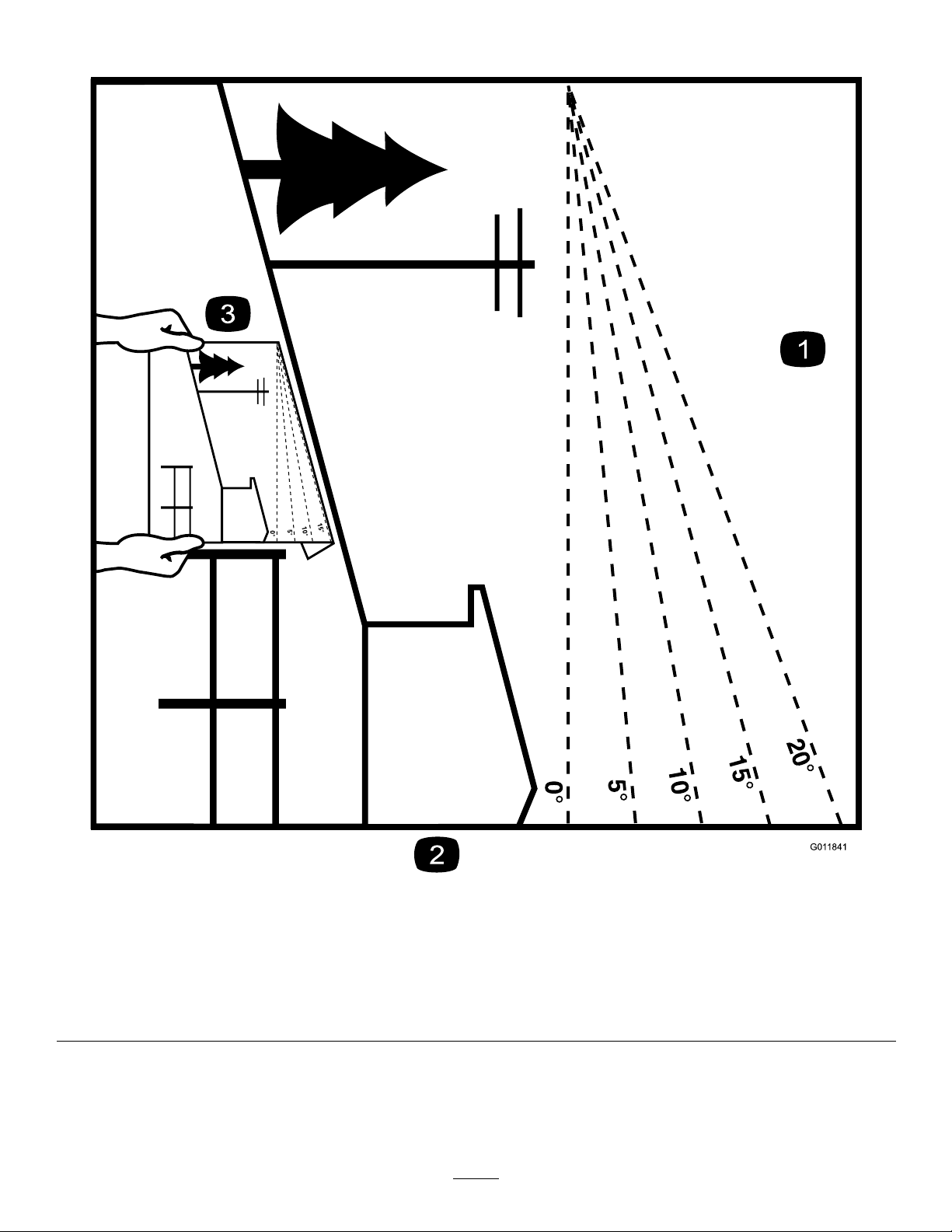
G011841
Figure3
Thispagemaybecopiedforpersonaluse.
1.Themaximumslopeyoucansafelyoperatethemachineonis15degrees.Usetheslopecharttodeterminethedegreeofslope
ofhillsbeforeoperating.Donotoperatethismachineonaslopegreaterthan15degrees.Foldalongtheappropriateline
tomatchtherecommendedslope.
2.Alignthisedgewithaverticalsurface,atree,building,fencepole,etc.
3.Exampleofhowtocompareslopewithfoldededge.
7
Page 8
SafetyandInstructional
Decals
Safetydecalsandinstructionsareeasilyvisibletotheoperatorandarelocatednearanyareaofpotential
danger.Replaceanydecalthatisdamagedorlost.
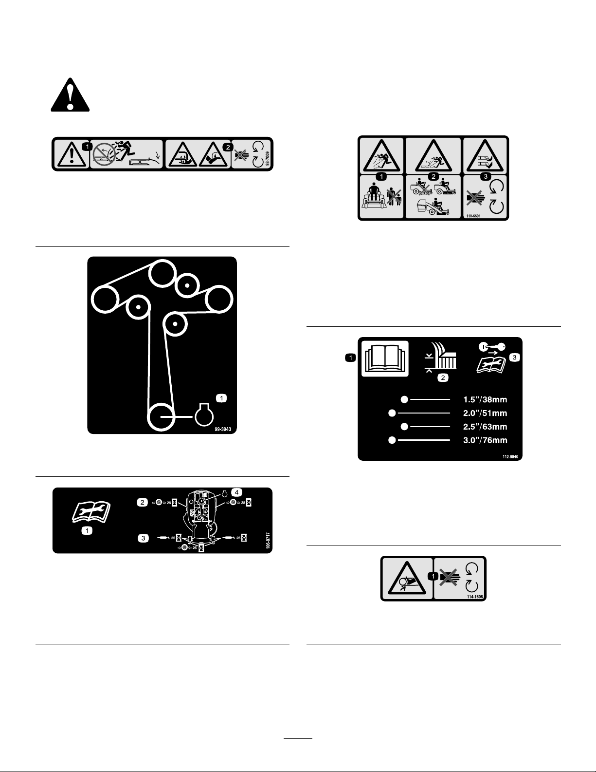
93-7009
1.Warning—don'toperatethemowerwiththedeectorupor
removed;keepthedeectorinplace.
2.Cutting/dismembermenthazardofhandorfoot,mower
blade—stayawayfrommovingparts.
110-6691
1.Thrownobjecthazard—keepbystandersasafedistance
fromthemachine.
2.Thrownobjecthazard,mower—donotoperatewithoutthe
deector,dischargecover,orgrasscollectionsystemin
place.
3.Cutting/dismembermentofhandorfoot—stayawayfrom
movingparts.
99-3943
1.Engine
106-8717
1.Readtheinstructionsbeforeservicingorperforming
maintenance.
2.Checktirepressureevery25operatinghours.
3.Greaseevery25operatinghours.
4.Engine
112-9840
1.ReadtheOperator's
Manual.
2.Heightofcut
3.Removetheignitionkey
andreadtheinstructions
beforeservicingor
performingmaintenance.
114-1606
1.Entanglementhazard,belt—keepallguardsinplace.
8
Page 9
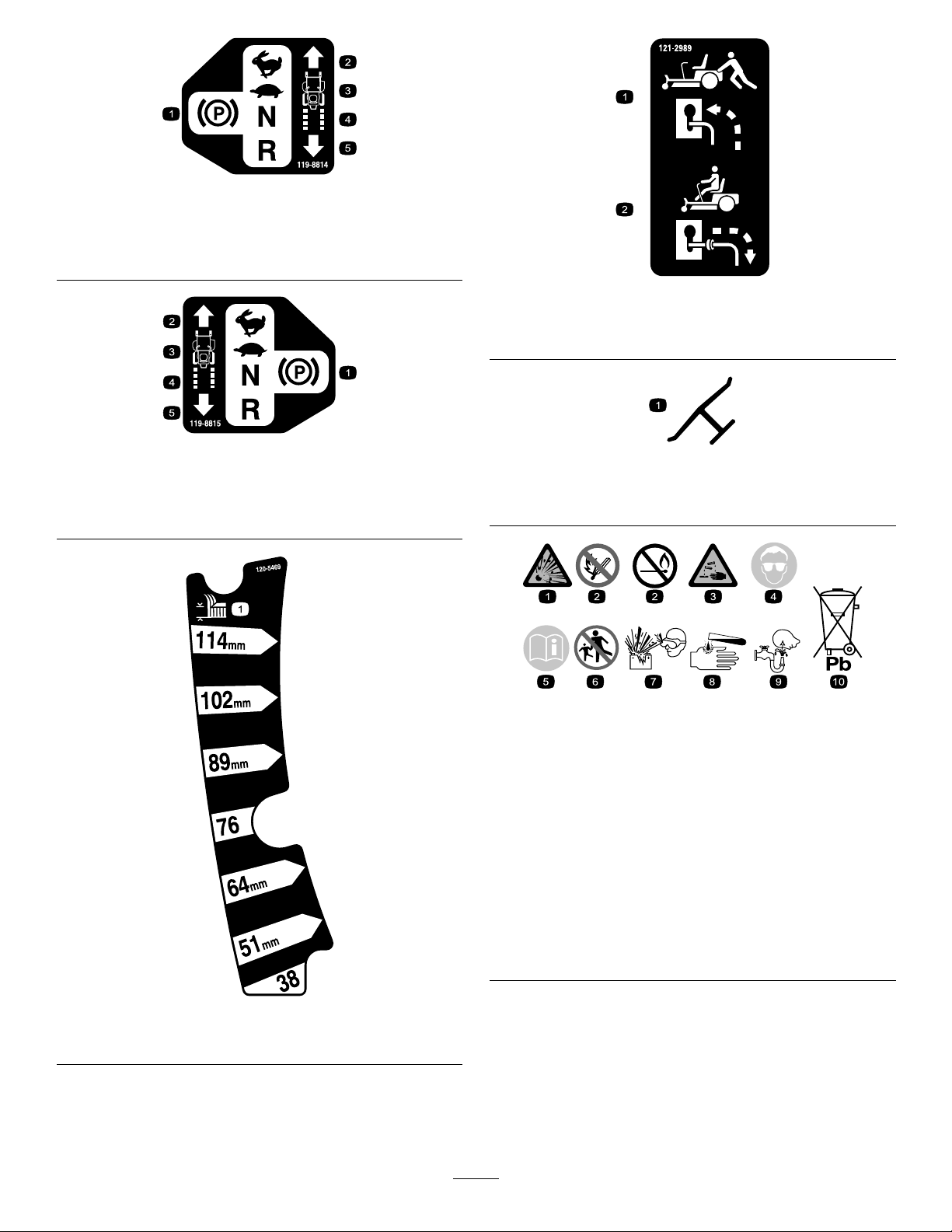
119-8814
1.Parkingposition4.Neutral
2.Fast5.Reverse
3.Slow
121-2989
119-8815
1.Parkingposition4.Neutral
2.Fast5.Reverse
3.Slow
1.Bypassleverpositionfor
pushingthemachine
2.Bypassleverpositionfor
operatingthemachine
Manufacturer'sMark
1.Indicatesthebladeisidentiedasapartfromtheoriginal
machinemanufacturer.
BatterySymbols
Someorallofthesesymbolsareonyourbattery
1.Explosionhazard
2.Nore,opename,or
smoking.
3.Causticliquid/chemical
burnhazard
4.Weareyeprotection9.Flusheyesimmediately
5.ReadtheOperator's
Manual.
6.Keepbystandersasafe
distancefromthebattery.
7.Weareyeprotection;
explosivegasescan
causeblindnessandother
injuries
8.Batteryacidcancause
blindnessorsevereburns.
withwaterandgetmedical
helpfast.
10.Containslead;donot
discard.
120-5470
1.Height-of-cut
9
Page 10
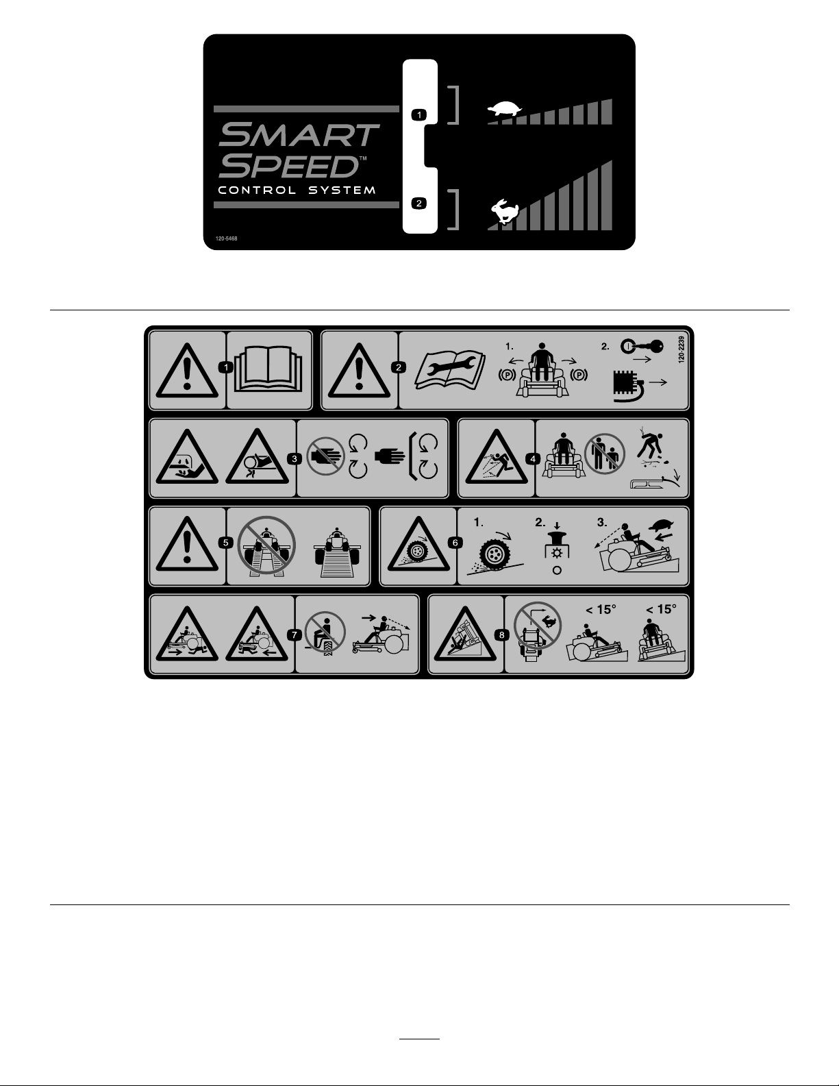
120-5468
1.Slowspeed
2.Fastspeed
120-2239
1.Warning—readtheOperator'sManual.5.Warning—donotusesplitramps,useafullrampswhen
2.Warning—readtheinstructionsbeforeservicingorperforming
maintenance;movethemotioncontrolleverstothepark
(brake)position,removetheignitionkeyanddisconnectthe
sparkplugwire.
3.Cutting/dismembermenthazard,mowerblade;entanglement
hazard,belt—stayawayfrommovingparts,keepallguards
andshieldsinplace.
4.Thrownobjecthazard—keepbystandersasafedistancefrom
themachine,pickupdebrisbeforeoperating,keepdeector
inplace.
transportingmachine.
6.Lossoftraction/controlhazard,slopes—lossoftraction/control
onaslope,disengagethebladecontrolswitch(PTO),
proceedofftheslopeslowly.
7.Crushing/dismembermenthazardofbystanders,reversing;
crushing/dismembermenthazardofbystanders—donotcarry
passengers,lookbehindanddownwhenreversing.
8.Tippinghazard—donotmowslopesgreaterthan15degrees,
avoidsuddenandsharpturnswhileonslopes.
10
Page 11
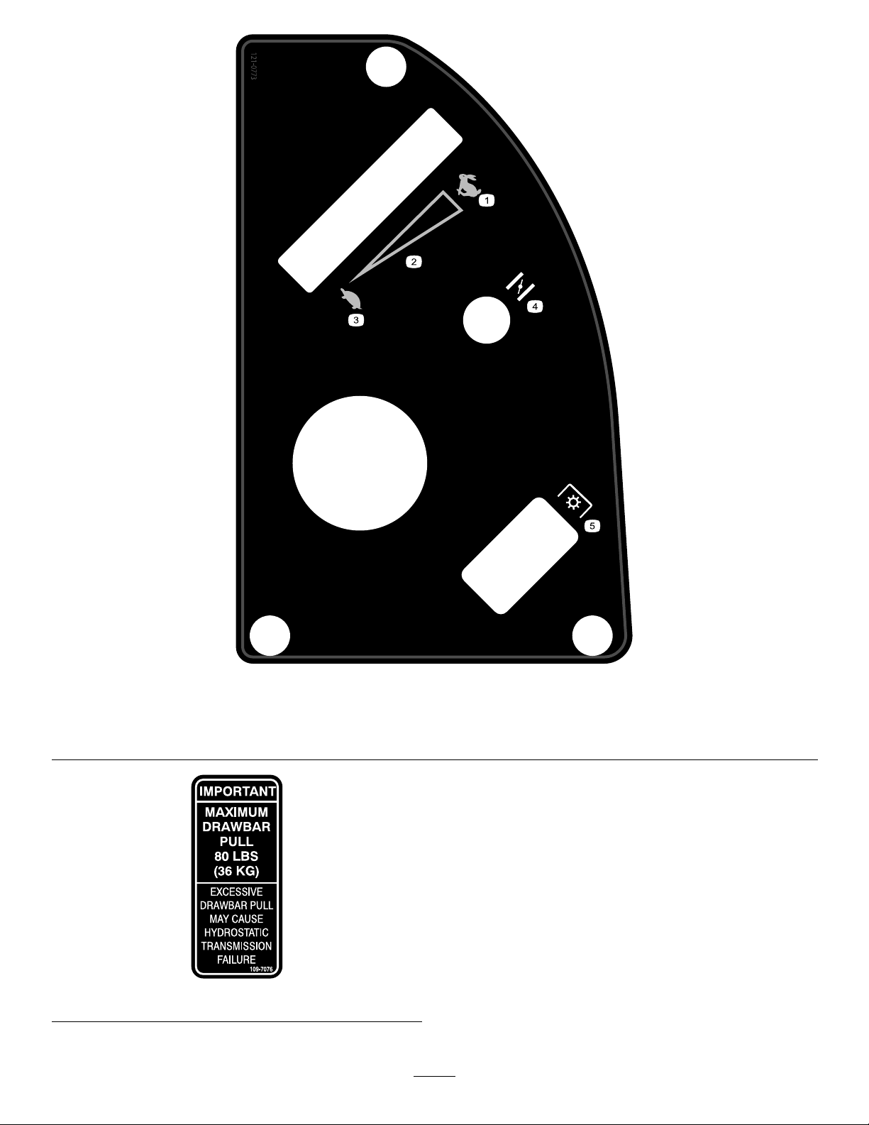
121-0773
1.Fast
2.Continuousvariablesetting5.Powertake-off(PTO),Bladecontrolswitch
3.Slow
4.Choke
109-7076
11
Page 12
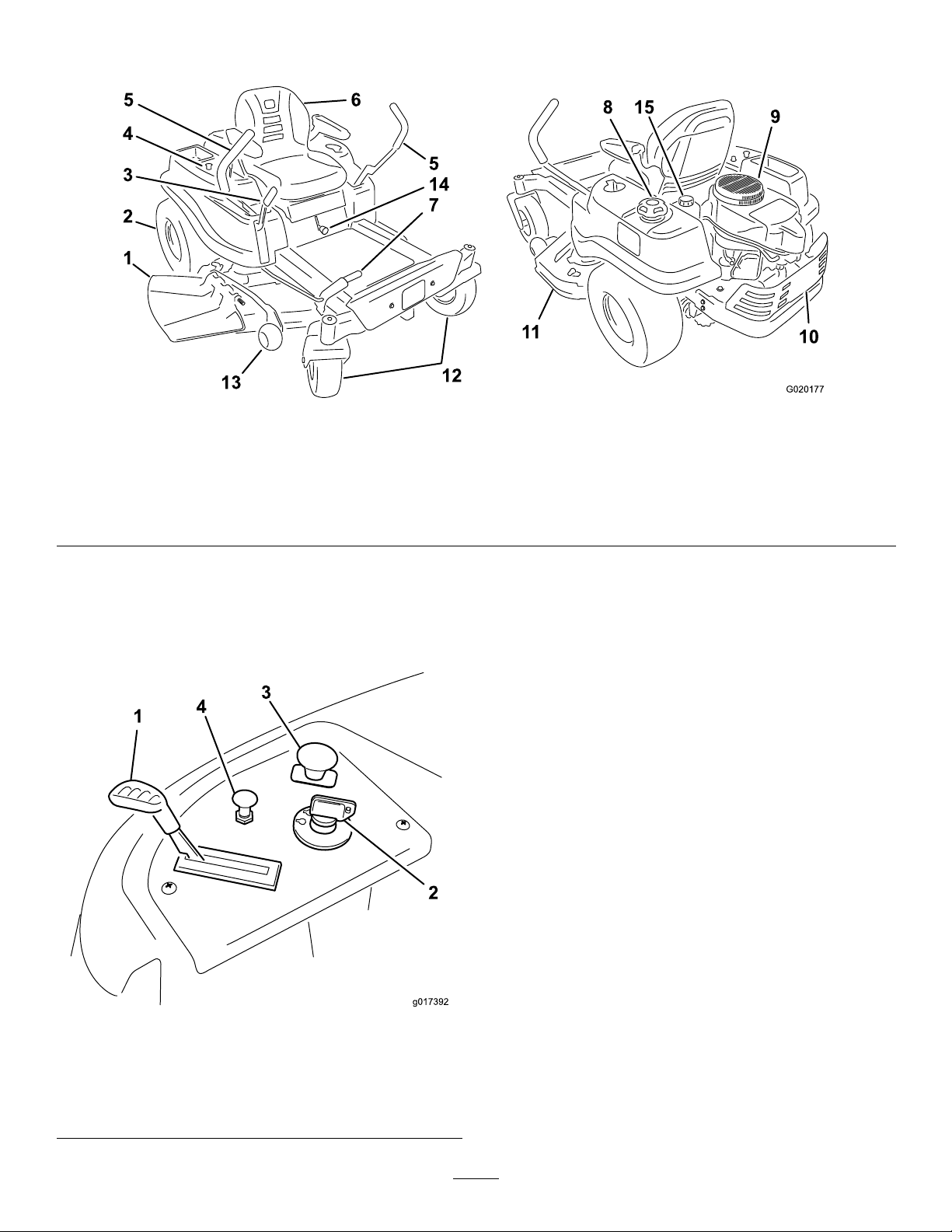
ProductOverview
G020177
4
3
2
1
8 15
9
10
11
12
13
6
5
14
7
5
Figure4
1.Deector
2.Reardrivewheel
3.Height-of-cutlever7.Foot-assistlever(certain
4.Controlpanel
5.Motion-controllevers9.Engine13.Anti-scalproller
6.Operatorseat
modelsonly)
8.Fuel-tankcap12.Frontcasterwheel
Controls
BecomefamiliarwithallofthecontrolsinFigure4and
Figure5beforeyoustarttheengineandoperatethemachine.
10.Engineguard
11.Mowerdeck15.Hydraulicreservoir
14.SmartSpeed™lever
IgnitionSwitch
Theignitionswitchhas3positions:Off,Run,andStart.The
keywillturntoStartandmovebacktoRunuponrelease.
TurningthekeytotheOffpositionwillstoptheengine;
however,alwaysremovethekeywhenleavingthemachine
topreventsomeonefromaccidentallystartingtheengine
(Figure5).
ThrottleControl
Thethrottlecontrolstheenginespeedandithasa
continuous-variablesettingfromSlowtoFast(Figure5).
ChokeControl
PullupontheChokecontroluntilitstopstochokethe
engine(Figure5).PushdownontheChokecontrolfor
normalengineoperation
1.Throttle3.Blade-controlswitch
Figure5
ControlPanel
2.Ignitionswitch
(powertake-off)
4.Choke
Blade-controlSwitch(PowerTake-Off)
Theblade-controlswitch,representedbyapowertake-off
(PTO)symbol,engagesanddisengagespowertothemower
blades(
12
Figure5).
Page 13
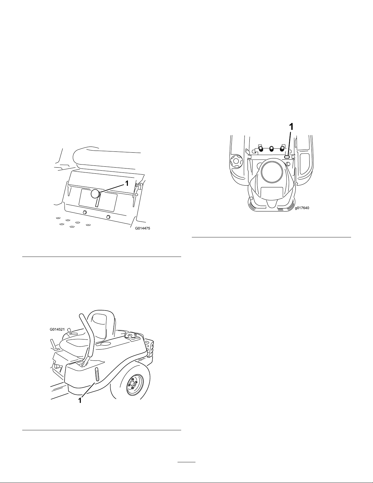
Motion-controlLeversandParking
G014475
1
G014521
1
g017640
1
BrakePosition
Themotion-controlleversarespeed-sensitivecontrolsof
independent-wheelmotors.Movingaleverforwardor
backwardturnsthewheelonthesamesideforwardorin
reverse;wheelspeedisproportionaltotheamountthelever
ismoved.Movethecontrolleversoutwardfromthecenter
totheparkposition,andexitthemachine(Figure18).Always
positionthemotion-controlleversintotheparkposition
whenyoustopthemachineorleaveitunattended.
SmartSpeed™ControlSystemLever
TheSmartSpeed™ControlSystemlever,locatedbelowthe
operatingposition,givestheoperatorachoicetodrivethe
machineat2speedranges—highandlow(Figure6).
Height-of-CutLever
Theheight-of-cutleverallowstheoperatortolowerand
raisethedeckfromtheseatedposition.Whentheleveris
movedup(towardtheoperator),thedeckisraisedfromthe
ground,andwhenmoveddown(awayfromtheoperator),it
isloweredtowardtheground.Onlyadjusttheheight-of-cut
whilethemachineisnotmoving(Figure22).
HourMeter
Thehourmeterrecordsthenumberofhourswhenthe
operatorisintheseatandtheignitionswitchisintheON
position(Figure8).
Figure6
1.Smartspeedlever
Fuel-presenceWindow
Thefuelwindowlocatedontheleft-handsideofthemachine
canbeusedtoverifythepresenceofgasolineinthetank
(Figure7).
Figure8
1.Hourmeterlocationbehindtheseat
1.Fuel-presencewindow
Figure7
13
Page 14

Operation
Note:Determinetheleftandrightsidesofthemachine
fromthenormaloperatingposition.
AddingFuel
•Forbestresults,useonlyclean,fresh(lessthan30days
old),unleadedgasolinewithanoctaneratingof87or
higher((R+M)/2ratingmethod).
•Ethanol:Gasolinewithupto10%ethanol(gasohol)
or15%MTBE(methyltertiarybutylether)byvolume
isacceptable.EthanolandMTBEarenotthesame.
Gasolinewith15%ethanol(E15)byvolumeisnot
approvedforuse.Neverusegasolinethatcontains
morethan10%ethanolbyvolume,suchasE15
(contains15%ethanol),E20(contains20%ethanol),or
E85(containsupto85%ethanol).Usingunapproved
gasolinemaycauseperformanceproblemsand/orengine
damagewhichmaynotbecoveredunderwarranty.
•Donotusegasolinecontainingmethanol.
•Donotstorefueleitherinthefueltankorfuelcontainers
overthewinterunlessafuelstabilizerisused.
•Donotaddoiltogasoline.
DANGER
Incertainconditionsduringfueling,static
electricitycanbereleasedcausingasparkwhich
canignitethegasolinevapors.Areorexplosion
fromgasolinecanburnyouandothersandcan
damageproperty.
•Alwaysplacegasolinecontainersontheground
awayfromyourvehiclebeforelling.
•Donotllgasolinecontainersinsideavehicleor
onatruckortrailerbedbecauseinteriorcarpets
orplastictruckbedlinersmayinsulatethe
containerandslowthelossofanystaticcharge.
•Whenpractical,removegas-poweredequipment
fromthetruckortrailerandrefueltheequipment
withitswheelsontheground.
•Ifthisisnotpossible,thenrefuelsuch
equipmentonatruckortrailerfromaportable
container,ratherthanfromagasolinedispenser
nozzle.
•Ifagasolinedispensernozzlemustbeused,
keepthenozzleincontactwiththerimofthe
fueltankorcontaineropeningatalltimesuntil
fuelingiscomplete.
DANGER
Incertainconditions,gasolineisextremely
ammableandhighlyexplosive.Areorexplosion
fromgasolinecanburnyouandothersandcan
damageproperty.
•Fillthefueltankoutdoors,inanopenarea,
whentheengineiscold.Wipeupanygasoline
thatspills.
•Neverllthefueltankinsideanenclosedtrailer.
•Donotllthefueltankcompletelyfull.Add
gasolinetothefueltankuntilthelevelis6to13
mm(1/4to1/2inch)belowthebottomofthe
llerneck.Thisemptyspaceinthetankallows
gasolinetoexpand.
•Neversmokewhenhandlinggasoline,andstay
awayfromanopenameorwheregasoline
fumesmaybeignitedbyaspark.
•Storegasolineinanapprovedcontainerand
keepitoutofthereachofchildren.Neverbuy
morethana30-daysupplyofgasoline.
•Donotoperatewithoutentireexhaustsystemin
placeandinproperworkingcondition.
WARNING
Gasolineisharmfulorfatalifswallowed.Long-term
exposuretovaporscancauseseriousinjuryand
illness.
•Avoidprolongedbreathingofvapors.
•Keepfaceawayfromnozzleandgastankor
conditionerbottleopening.
•Avoidcontactwithskin;washoffspillagewith
soapandwater.
UsingStabilizer/Conditioner
Useafuelstabilizer/conditionerinthemachinetoprovide
thefollowingbenets:
•Keepsgasolinefreshduringstorageof90daysorless.
Forlongerstorageitisrecommendedthatthefueltank
bedrained.
•Cleanstheenginewhileitruns
•Eliminatesgum-likevarnishbuildupinthefuelsystem,
whichcauseshardstarting
Important:Donotusefueladditivescontaining
methanolorethanol.
Addthecorrectamountofgasstabilizer/conditionerto
thegas.
Note:Afuelstabilizer/conditionerismosteffective
whenmixedwithfreshgasoline.T ominimizethechance
14
Page 15
ofvarnishdepositsinthefuelsystem,usefuelstabilizer
G014474
1
2
3
4
5
6
G014895
1
2
3
4
atalltimes.
3.Installthefuel-tankcapsecurely ,andtightenuntilit
clicks.
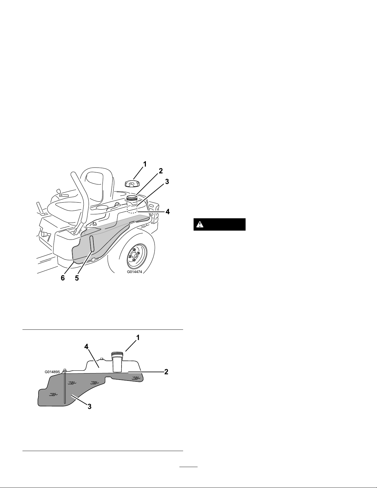
FillingtheFuelTank
Ensurethattheengineisshutoffandthemotioncontrolsare
intheparkedposition.
Important:Donotoverllfueltank.Fillthefueltank
tothebottomofthellerneck.Theemptyspaceinthe
tankallowsthefueltoexpand.Overllingmayresultin
fuelleakage,damagetotheengine,ordamagetothe
emissionssystem.
1.Cleanaroundthefuel-tankcapandremovethecap.
Note:Youcanusethefuelwindowtoverifythe
presenceofgasolinebeforellingthetank(
2.Slowlyaddgasolineuntilthefuelreachesthebaseof
thellerneck(
Figure9).
Figure9).
CheckingtheEngine-oilLevel
Beforeyoustarttheengineandusethemachine,checktheoil
levelintheenginecrankcase;refertoCheckingtheEngine-oil
Level(page28).
BreakingInaNewMachine
Newenginestaketimetodevelopfullpower.Mowerdecks
anddrivesystemshavehigherfrictionwhennew,placing
additionalloadontheengine.Allow40to50hoursof
break-intimefornewmachinestodevelopfullpowerand
bestperformance.
ThinkSafetyFirst
OperatingSafety
Pleasecarefullyreadallofthesafetyinstructionsanddecals
inthesafetysection.Knowingthisinformationcouldhelp
you,yourfamily ,pets,orbystandersavoidinjury.
Figure9
1.Fuel-tankcap
2.Fillopening5.Fuelwindow
3.Fillerneck
4.Baseofthellerneck(do
notllpasthere)
6.Endofthefueltank
DANGER
Mowingonwetgrassorsteepslopescancause
slidingandlossofcontrol.
Wheelsdroppingoveredgescancauserollovers,
whichmayresultinseriousinjury,death,or
drowning.
Alossoftractionisalossofsteeringcontrol.
Toavoidlossofcontrolandpossibilityofrollover:
•Donotmowneardrop-offsornearwater.
•Donotmowslopesgreaterthan15degrees.
•Reducethespeedanduseextremecautionon
slopes.
•Whenmowingslopes,graduallyworkfrom
lowertohigherareasontheincline.
•Avoidsuddenturnsorrapidspeedchanges.
•Turnup,intoaninclinewhenchanging
directionsonslopes.Turningdowntheslope
reducestraction.
Figure10
1.Fillopening3.Fuel
2.Baseofthellerneck(do
notllpasthere)
4.Emptyspace(forfuel
expansion)
•Attachmentschangethehandlingcharacteristics
ofthemachine.Useextracautionwhenusing
attachmentswiththemachine.
15
Page 16
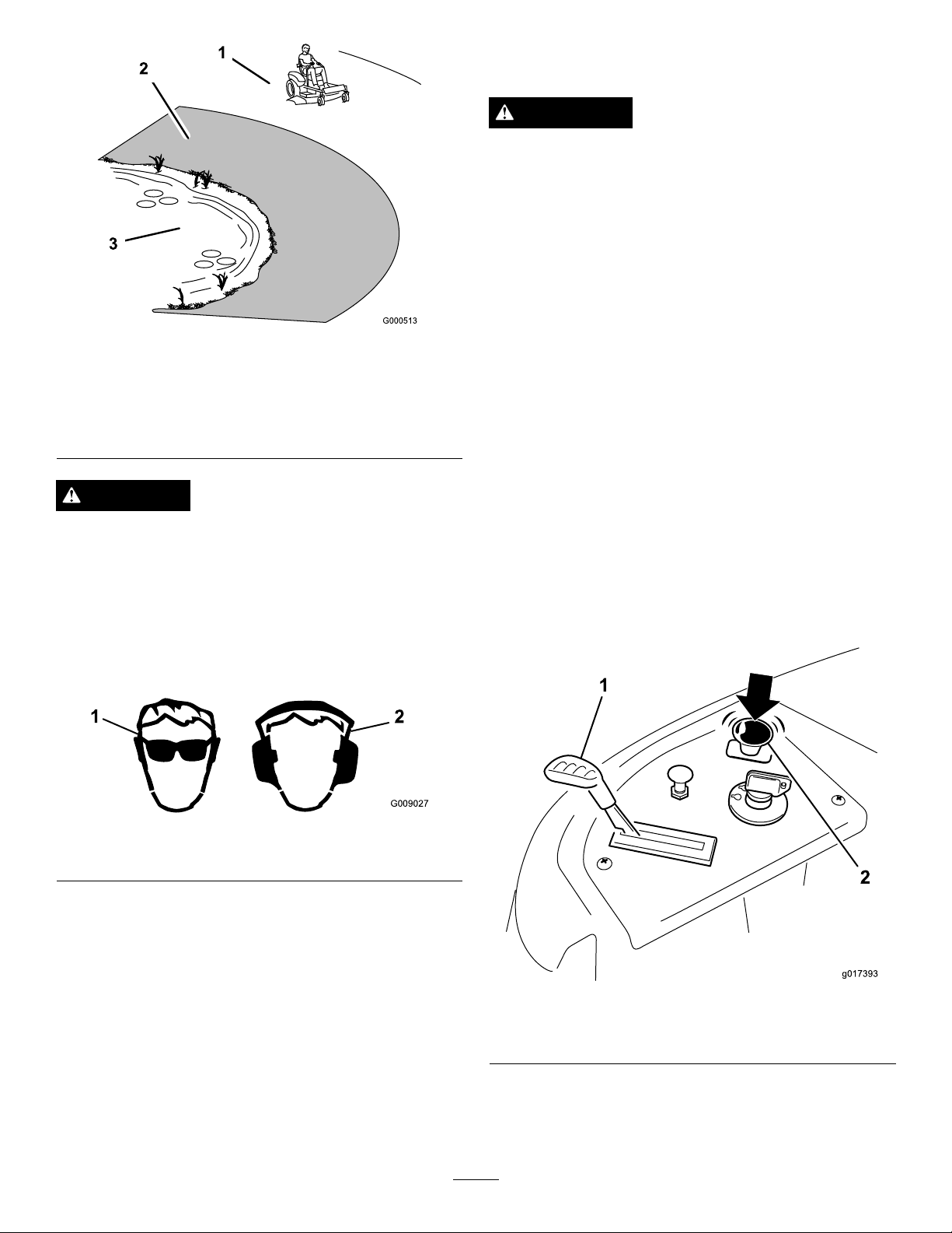
1.Safezone—usethe
G009027
1
2
TimeCutterhere
2.Useawalk-behindmower
and/orhandtrimmernear
drop-offsandwater.
Figure11
3.Water
UnderstandingtheSafety-interlock
System
WARNING
Ifsafety-interlockswitchesaredisconnectedor
damaged,themachinecouldoperateunexpectedly
causingpersonalinjury.
•Donottamperwiththeinterlockswitches.
•Checktheoperationoftheinterlockswitches
daily,andreplaceanydamagedswitchesbefore
operatingthemachine.
Thesafety-interlocksystemisdesignedtopreventtheengine
fromstartingunless:
•Thebladesaredisengaged.
•Themotion-controlleversareintheparkposition.
Thesafety-interlocksystemalsoisdesignedtostoptheengine
wheneverthecontrolleversareoutoftheparkpositionand
yourisefromtheseat.
CAUTION
Thismachineproducessoundlevelsinexcessof85
dBAattheoperatorsearandcancausehearingloss
throughextendedperiodsofexposure.
Wearhearingprotectionwhenoperatingthis
machine.
Theuseofprotectiveequipmentforeyes,ears,feet,andhead
isrecommended.
Figure12
1.Wearsafetyglasses
2.Wearhearingprotection
StartingtheEngine
1.Sitdownontheseatandmovethemotioncontrols
outwardtotheparkposition.
2.Movethethrottletothefastposition(
3.Disengagethebladesbymovingtheblade-control
switchtoOff(Figure13).
Figure13).
Figure13
1.Throttle
4.PullupontheChokecontrolbeforestartingacold
engine(Figure14).
16
Note:Awarmorhotenginemaynotrequirechoking.
2.Blade-controlswitch—Off
position
Page 17

g017699
4
5
Figure14
g017700
2
3
4
5
6
Figure15
1.Controlpanel4.Slow
2.Throttle
3.Fast
5.Chokecontrol
5.TurntheignitionkeytoStarttoenergizethestarter
(Figure15).
Note:Whentheenginestarts,releasethekey.
Important:Donotengagethestarterformore
than10secondsatatime.Iftheenginefailsto
start,allowa60-secondcool-downperiodbetween
attempts.Failuretofollowtheseinstructionscan
damagethestartermotor.
1.Controlpanel4.Off
2.Chokecontrol
3.Ignitionkey
5.Run
6.Start
6.Aftertheenginestarts,pushdownontheChoke
control(
Figure15).
Note:Iftheenginestallsorhesitates,pulluponthe
Chokecontrolandlettheenginerunforafewseconds.
ThenpushdownontheChokecontrol.Repeatthis
asrequired.
OperatingtheBlades
Theblade-controlswitch,representedbyapowertake-off
(PTO)symbol,engagesanddisengagespowertothemower
blades.Thisswitchcontrolspowertoanyattachmentsthat
drawpowerfromtheengine,includingthemowerdeckand
cuttingblades.
EngagingtheBlades
Important:Donotengagethebladeswhenparkedin
tallgrass.Beltorclutchdamagecanoccur.
1.Releasepressureonthemotion-controlleversand
placethemachineinneutral.
2.MovethethrottletotheFastposition.
Note:Alwaysengagethebladeswiththethrottlein
theFastposition.
3.Pullupontheblade-controlswitchtomoveittothe
Onposition,andengagetheblades(
Figure16).
17
Page 18

Figure16
1.Controlpanel2.Blade-controlswitch—On
position
TestingtheSafety-interlock System
Testthesafety-interlocksystembeforeyouusethemachine
eachtime.Ifthesafetysystemdoesnotoperateasdescribed
below,haveanAuthorizedServiceDealerrepairthesafety
systemimmediately.
1.Whilesittingontheseat,withthecontrolleversinpark
position,andmovetheblade-controlswitchtoOn.
2.Trystartingtheengine;theengineshouldnotcrank.
3.Whilesittingontheseat,movetheblade-control
switchtoOff.
4.Moveeithermotion-controllevertothecenter,
unlockedposition.
5.Trystartingtheengine;theengineshouldnotcrank.
6.Repeatwiththeothermotion-controllever.
7.Whilesittingontheseat,movetheblade-control
switchtoOff,andlockthemotion-controlleversin
theparkposition.
DisengagingtheBlades
Pushdownontheblade-controlswitchtomoveittotheOff
position,anddisengagetheblades(Figure17).
Figure17
1.Controlpanel2.Blade-controlswitch—Off
8.Starttheengine.
9.Whiletheengineisrunning,engagetheblade-control
switch,andriseslightlyfromtheseat.
Note:Theengineshouldstop.
10.Whilesittingontheseat,movetheblade-control
switchtoOff,andlockthemotion-controlleversin
theparkposition.
11.Starttheengine.
12.Whiletheengineisrunning,movethemotion-control
leverstothecenter,unlockedposition,engagethe
blade-controlswitch,andriseslightlyfromtheseat.
Note:Theengineshouldstop.
StoppingtheEngine
1.MovethethrottlelevertotheSlowposition.
2.Lowertheenginespeedtoidlespeed,andallowitto
runforatleastoneminute.
3.Disengagethebladesbymovingtheblade-control
switchtoOff(Figure17).
4.TurntheignitionkeytoOff(Figure15)andremove
thekey.
18
Page 19

Driving
G014475
1
Drivingthemachinebenetsfromanunderstandingof
whatzero-turn-radiusmowermeans.Thedrivewheelsturn
independently,poweredbyhydraulicmotorsoneachaxle;
henceonesidecanturninreversewhiletheotherturns
forwardcausingthemachinetospinratherthanturn.This
vastlyimprovesthemachinemaneuverabilitybutmayrequire
someadjustmentiftheoperatorisunfamiliar.
WARNING
Themachinecanspinveryrapidly.Theoperator
maylosecontrolofthemachineandcausepersonal
injuryordamagetothemachine.
•Usecautionwhenmakingturns.
•Slowthemachinedownbeforemakingsharp
turns.
UsingtheSmartSpeed™Control
System
TheSmartSpeed™Control-Systemlever,locatedbelowthe
operatingposition(Figure19),givestheoperatorachoiceto
drivethemachineat2groundspeedranges—highandlow .
Figure19
Thethrottlecontrolregulatestheenginespeedasmeasured
inrpm(revolutionsperminute).Placingthethrottlecontrol
intheFastpositioncanbebestforperformance.Formost
applications,operatinginthefull-throttlepositionisdesirable.
1.Smart-speedlever
Tochangespeeds:
1.Movethemotioncontrolleverstoneutralandoutward
totheparkposition;disengagethebladecontrolswitch.
WARNING
Removingyourhandsfromthemotion-control
leverswhilethemachineisinmotioncan
resultinalossofcontrolcausingharmtoyou
orbystanders.
Alwaysstopthemachineandmovethe
motion-controlleverstotheparkposition
beforeadjustingtheSmartSpeed™Control
System.
2.Adjustthelevertothedesiredposition.
1.Park(brake)position
2.Center,unlockposition
Figure18
3.Forward
4.Backward
19
Page 20

DrivingForward
G008952
G008953
DrivingBackward
1.Movetheleverstothecenter,unlockedposition.
2.Togoforward,slowlypushthemotion-controllevers
forward(Figure18).
Figure20
Togostraight,applyequalpressuretoboth
motion-controllevers(Figure18).
Toturn,releasepressureonthemotion-controllever
towardthedirectionyouwanttoturn(Figure18).
1.Movetheleverstothecenter,unlockedposition.
2.Togobackward,lookbehindyouanddown,asyou
slowlypullthemotion-controlleversrearward(Figure
21).
Figure21
Togostraight,applyequalpressuretoboth
motion-controllevers(Figure21).
Toturn,releasethepressureonthemotion-control
levertowardthedirectionyouwanttoturn.
Tostop,pushthemotion-controlleverstoneutral.
Thefartheryoumovethemotion-controlleversin
eitherdirection,thefasterthemachinewillmovein
thatdirection.
Tostop,pullthemotion-controlleverstoneutral.
StoppingtheMachine
Tostopthemachine,movethemotion-controlleversto
neutralandoutwardtotheparkposition,disengagethe
blade-controlswitch,ensurethethrottleisintheFast
position,andturntheignitionkeytooff.
Note:Remembertoremovethekeyfromtheignitionswitch.
WARNING
Childrenorbystandersmaybeinjuredifthey
moveorattempttooperatethemowerwhileitis
unattended.
Alwaysremovetheignitionkeyandmovethe
motion-controlleversoutwardtotheparkposition
whenleavingthemachineunattended,evenifjust
forafewminutes.
20
Page 21

AdjustingtheHeight-of-Cut
g021929
G010233
1
2
3
4
1
G014969
Height-of-cutiscontrolledbytheleverlocatedtotherightof
theoperatingposition(Figure22).
1.Pullupandinwardonthelevertomoveittothe
desiredcuttingposition.
2.Onceatthedesiredcuttingposition,slowlylowerthe
leveruntilitengagestheposition.
Thetransportpositionisthehighestheight-of-cutpositionor
cuttingheight,114mm(4.5inches)asshownin
Figure22.
Figure23
1.Anti-scalproller3.Flangenut
2.Bolt4.Holespacing
PositioningtheSeat
Whilesittingintheoperator’sposition,raisethe
seat-adjustmentleverslightly,andmovetheseatforwardor
backwardtothedesiredposition(Figure24).
Figure22
1.Height-of-cutlever3.114mm(4.5
2.Height-of-cutpositions
inches)—Transport
position
AdjustingtheAnti-scalp Rollers
Wheneveryouchangetheheight-of-cut,adjusttheheight
oftheanti-scalprollers.
Note:Adjusttheanti-scalprollers,sotherollersdonot
touchthegroundinnormal,atmowingareas.
1.Disengagetheblade-controlswitch(PTO),movethe
motion-controlleverstotheneutral-lockposition,and
settheparkingbrake.
2.Stoptheengine,removethekey,andwaitforallmoving
partstostopbeforeleavingtheoperatingposition.
3.Adjusttheanti-scalprollerstomatchtheclosest
height-of-cutposition(
Figure23).
Figure24
21
Page 22

AdjustingtheMotion-control
4
1
2
G014970
3
g017303
1 2
3
Levers
PushingtheMachine
1.Parkthemachineonalevelsurface,anddisengagethe
blade-controlswitch.
AdjustingtheHeight
Themotion-controlleverscanbeadjustedhigherorlowerfor
maximumoperatorcomfort.
1.Removethe2boltsholdingthecontrollevertothe
control-armshaft(Figure25).
2.Movethecontrollevertothenextsetofholes.
3.Securetheleverwiththe2bolts(Figure25).
Figure25
1.Control-armshaft3.Slotted,upperhole
2.Controllever
4.Bolt
2.Movethemotion-controlleversoutwardtothepark
position,stoptheengine,andwaitforallmovingparts
tostopbeforeleavingtheoperatingposition.
3.Locatethebypassleversontheframeonbothsidesof
theengine.
4.Movethebypassleversforwardthroughthekeyhole
anddowntolocktheminplace(
Note:Ensurethisisdoneforeachlever.
5.Movethemotion-controlleversinwardtotheneutral
positionandturntheignitionkeytotheRunposition.
Note:Donotstartthemachine.
Note:Themachineisnowabletobepushedbyhand.
Figure26).
4.Repeattheadjustmentfortheoppositecontrollever.
AdjustingtheTilt
Themotion-controlleverscanbetiltedforeoraftfor
maximumoperatorcomfort.
1.Loosentheupperboltholdingthecontrollevertothe
control-armshaft.
2.Loosenthelowerboltjustenoughtopivotthecontrol
leverforeoraft(Figure25).Tightenbothboltsto
securethecontrolinthenewposition.
3.Repeattheadjustmentfortheoppositecontrollever.
PushingtheMachinebyHand
Important:Alwayspushthemachinebyhand.Donot
towthemachine,becausedamagemayoccur.
Thismachinehasanelectric-brakemechanism,andtopush
themachine,theignitionkeyneedstobeintheRunposition.
Thebatteryneedstobechargedandfunctioningforthe
electricbraketobedisengage.
Figure26
1.Bypass-leverlocations
2.Leverpositionfor
operatingthemachine
6.Whennished,ensurethatthekeyhasbeenreturnedto
theStoppositiontoavoiddrainingthebatterycharge.
Note:Ifthemachinefailstomove,theelectricbrakemay
stillbeengaged.Ifnecessary,theelectricbrakecanbereleased
manually;refertoReleasingtheElectricBrake(page35).
3.Leverpositionforpushing
themachine
OperatingtheMachine
Movethebypassleversrearwardthroughthekeyholeand
downtolocktheminplaceasshowninFigure26.
Note:Ensurethisisdoneforeachlever.
22
Page 23

ConvertingtoSide-discharge
G018654
1
2
3
1
4
G021583
1
2
3
4
1
5
5
G018020
1
Mode
WARNING
Openholesinthemowerdeckexposeyouand
otherstothrowndebris.Debristhrownoutofthe
holesinthemowerdeckcancauseinjury.
•Neveroperatethemowerdeckwithouthardware
mountedinallholesinthemowerdeck.
•Installhardwareinthemountingholeswhen
youremoveabafe.
1.Stoptheengineandremovetheignitionkey.
2.Removethemowerdeck;refertoRemovingtheMower
(page43).
3.Turnthemowerdeckupsidedown.
4.Removetheexistingmowerbladesinstalledonyour
mowerdeck;refertoRemovingtheBlades(page41).
5.Removeanydebrisandgrassclippingsfromthe
undersideofthemowerdeck.
6.Removetheleft-handbafefromthemowerdeck,and
plugtheopenholeswithnutsandbolts(Figure27).
Figure28
Thedeectorhasbeenremovedforthepurposeof
clarity.
1.Flangenut4.Weldedposts
2.Carriagebolt
3.Right-handbafe
8.RemovetheRecycler
5.Plugtheholeswithnuts
andboltshere.
®
bracketfromthemowerdeck
(Figure29).
Figure27
1.Locknut
2.Weldedposts4.Plugtheholeswithnuts
3.Leftbafe
andboltshere.
7.Removetheright-handbafefromthemowerdeck,
andplugtheopenholeswithnutsandbolts(Figure28).
Figure29
1.Recyclerbracket
9.Installthecutoffbafe(suppliedwiththemower)at
theside-dischargeopeningonthemowerdeck(Figure
30).
23
Page 24

G018016
1
Figure30
1.Cutoffbafe
10.Foroptimumperformanceinsidedischargemode,
installtheside-dischargeblades;refertoInstallingthe
Blades(page41).
Note:ContactanAuthorizedToroDealerforthe
correctblades.
11.Installthemowerdeck;refertoInstallingtheMower
(page44).
24
Page 25

OperatingTips
UsingtheFastThrottleSetting
Forbestmowingandmaximumaircirculation,operate
theengineattheFastthrottleposition.Airisrequiredto
thoroughlycutgrassclippings,sodonotsettheheight-of-cut
solowastototallysurroundthemowerbyuncutgrass.
Alwaystrytohaveonesideofthemowerfreefromuncut
grass,whichallowsairtobedrawnintothemower.
UsingtheSmartSpeed™Control
System
TheSmartSpeed™Control-Systemlever,locatedbelow
theoperatingposition,givestheoperatorachoicetodrive
themachineat2speedranges—highandlow.Anoperator
canbenetfromthelowerspeedsettingwhenmaneuvering
themachineintightspacesoroperatingarounddelicate
landscapes.Thelowsettingcanalsobeusedtooperatethe
machineatahighthrottlesettingandbladespeed,whilestill
beingabletoreducethegroundspeedtoincreasethequality
ofcut.
CuttingLongGrass
Ifthegrassiseverallowedtogrowslightlylongerthan
normal,orifitcontainsahighdegreeofmoisture,raisethe
cuttingheighthigherthanusualandcutthegrassatthis
setting.Thencutthegrassagainusingthelower,normal
setting.
Stopping
Ifthemachine'sforwardmotionmustbestoppedwhile
mowing,aclumpofgrassclippingsmaydropontoyour
lawn.Toavoidthis,moveontoapreviouslycutareawiththe
bladesengagedoryoucandisengagethemowerdeckwhile
movingforward.
KeepingtheUndersideoftheMower
Clean
Cleanclippingsanddirtfromtheundersideofthemower
aftereachuse.Ifgrassanddirtbuildupinsidethemower,
cuttingqualitywilleventuallybecomeunsatisfactory.
CuttingaLawnfortheFirstTime
Cutgrassslightlylongerthannormaltoensurethatthe
cuttingheightofthemowerdoesnotscalpanyuneven
ground.However,thecuttingheightusedinthepastis
generallythebestonetouse.Whencuttinggrasslongerthan
sixinchestall,youmaywanttocutthelawntwicetoensure
anacceptablequalityofcut.
Cutting1/3oftheGrassBlade
Itisbesttocutonlyabout1/3ofthegrassblade.Cutting
morethanthatisnotrecommendedunlessgrassissparse,or
itislatefallwhengrassgrowsmoreslowly.
MowingDirection
Alternatethemowingdirectiontokeepthegrassstanding
straight.Thisalsohelpsdisperseclippingswhichenhances
decompositionandfertilization.
MowingatCorrectIntervals
Normally,mowevery4days.But,remember,grassgrowsat
differentratesatdifferenttimes.Sotomaintainthesame
cuttingheight,whichisagoodpractice,andmowmoreoften
inearlyspring.Asthegrassgrowthrateslowsinmidsummer,
mowlessfrequently.Ifyoucannotmowforanextended
period,rstmowatahighcuttingheight,thenmowagain2
dayslateratalowerheightsetting.
MaintainingtheBlade(s)
Maintainasharpbladethroughoutthecuttingseasonbecause
asharpbladecutscleanlywithouttearingorshreddingthe
grassblades.Tearingandshreddingturnsgrassbrownat
theedges,whichslowsgrowthandincreasesthechanceof
disease.Checkthemowerbladesaftereachuseforsharpness,
andforanywearordamage.Filedownanynicksandsharpen
thebladesasnecessary.Ifabladeisdamagedorworn,replace
itimmediatelywithagenuineTororeplacementblade.
AvoidingCuttingTooLow
Ifthecuttingwidthofthemoweriswiderthanthemower
youpreviouslyused,raisethecuttingheighttoensurethat
uneventurfisnotcuttooshort.
25
Page 26

Maintenance
Note:Determinetheleftandrightsidesofthemachinefromthenormaloperatingposition.
RecommendedMaintenanceSchedule(s)
MaintenanceService
Interval
Aftertherst8hours
Aftertherst50hours
Beforeeachuseordaily
Aftereachuse
Every25hours
Every100hours
Every200hours
Every400hours
MaintenanceProcedure
•Changetheengineoil.
•Changetheoilandltersforthehydraulicsystem,andbleedthesystem.
•Checkthesafety-interlocksystem.
•Checktheengine-oillevel.
•Cleantheair-intakescreen.
•Checkthecuttingblades.
•Inspectthegrassdeectorfordamage.
•Cleanthemower-deckhousing.
•Greaseallthelubricationpoints.
•Checktirepressure.
•Checktheoillevelintheexpansiontank.
•Checkthebeltsforwearorcracks.
•Servicethepaperelement(moreoftenindusty ,dirtyconditions).
•Changetheengineoil(moreoftenindusty,dirtyconditions).
•Checkthesparkplug(s).
•Replacethein-linefuellter.
•Replacethepaperelement(moreoftenindusty ,dirtyconditions).
•Changetheoillter(moreoftenindusty,dirtyconditions).
•Changetheoilandltersforthehydraulicsystem,andbleedthesystem.
•Chargethebatteryanddisconnectbatterycables.
Beforestorage
•Performallmaintenanceprocedureslistedabovebeforestorage.
•Paintanychippedsurfaces.
Important:Refertoyourengineoperator'smanualforadditionalmaintenanceprocedures.
CAUTION
Ifyouleavethekeyintheignitionswitch,someonecouldaccidentlystarttheengineandseriouslyinjure
youorotherbystanders.
Removethekeyfromtheignitionanddisconnectthewirefromthesparkplugbeforeyoudoany
maintenance.Setthewireasidesothatitdoesnotaccidentallycontactthesparkplug.
26
Page 27

Premaintenance
1
G014522
Lubrication
Procedures
RaisingtheSeat
Makesurethemotioncontrolleversarelockedinthepark
position.Lifttheseatforward.
Thefollowingcomponentscanbeaccessedbyraisingtheseat:
•Serialplate
•Servicedecal
•Seat-adjustmentbolts
•Fuellter
•Batteryandbatterycables
GreasingtheBearings
ServiceInterval:Every25hours—Greaseallthelubrication
points.
GreaseType:No.2GeneralPurpose,Lithium-BaseGrease
1.Parkthemachineonalevelsurface,anddisengagethe
blade-controlswitch.
2.Movethemotion-controlleversoutwardtothepark
position,stoptheengine,removethekey ,andwaitfor
allmovingpartstostopbeforeleavingtheoperating
position.
3.Cleanthegreasettings(Figure31andFigure32)with
arag.
Note:Makesuretoscrapeanypaintoffofthefront
ofthetting(s).
Figure31
1.Frontcastertire
Figure32
Locatedontheseat-panunderside
1.Readtheinstructions
beforeservicingor
performingmaintenance
2.Checkthetirepressure
every25operatinghours
3.Greaseevery25operating
hours
4.Engine
4.Connectagreaseguntoeachtting(Figure31and
Figure32).
5.Pumpgreaseintothettingsuntilgreasebeginsto
oozeoutofthebearings.
27
Page 28

EngineMaintenance
G014908
1
2
3
g017470
SAE V iscosity Grades
SAE 40
SAE 30
SAE 10W– 30/ SAE 10W– 40
-20 0 20 32 40 60 80 100
-30 -20 -10 0 10 20 30 40
°F
°C
STARTING TEMPERA TURE RANGE ANTICIPATED BEFORE NEXT OIL CHANGE
SAE 5W– 20
ServicingtheAirCleaner
Note:Servicetheaircleanermorefrequently(everyfew
hours)ifoperatingconditionsareextremelydustyorsandy.
Important:Nevercleanthepaperelementwith
pressurizedairorliquids,suchassolvent,gas,
orkerosene.Replacethepaperelementifitis
damagedorcannotbecleanedthoroughly.
ServicingtheEngineOil
RemovingthePaperElement
1.Parkthemachineonalevelsurfaceanddisengagethe
blade-controlswitch(PTO).
2.Movethemotion-controlleverstothebrakeposition,
stoptheengine,removethekey,andwaitforallmoving
partstostopbeforeleavingtheoperatingposition.
3.Cleanaroundtheair-cleanercovertopreventdirtfrom
gettingintotheengineandcausingdamage.
4.Liftthecover,andremovethehoseclampsecuringthe
air-cleanerassemblytotheengine(
5.Loosenthehoseclampandremovethepaperelement
(Figure33).
Figure33).
OilType:Detergentoil(APIserviceSF,SG,SH,SJ,orSL)
CrankcaseCapacity:withalterchange,2.1L(70oz);
withoutalterchange,1.8L(61oz)
Viscosity:Seethetablebelow.
Figure34
Note:Usingmulti-gradeoils(5W-20,10W -30,and10W -40)
willincreaseoilconsumption.Checktheoillevelmore
frequentlywhenusingthem.
CheckingtheEngine-oilLevel
ServiceInterval:Beforeeachuseordaily
Note:Checktheoilwhentheengineiscold.
WARNING
Figure33
1.Cover
2.Paperelement
3.Hoseclamp
CleaningthePaperElement
ServiceInterval:Every100hours—Servicethepaper
Every200hours/Yearly(whichevercomes
rst)—Replacethepaperelement(moreoftenin
dusty,dirtyconditions).
1.Lightlytaptheelementonaatsurfacetoremovedust
anddirt.
2.Inspecttheelementfortears,anoilylm,anddamage
totheseal.
element(moreoftenindusty,dirty
conditions).
Contactwithhotsurfacesmaycausepersonal
injury.
Keephands,feet,face,clothing,andotherbody
partsawaythemuferandotherhotsurfaces.
Important:Donotoverllthecrankcasewithoil,
becausedamagetotheenginemayresult.Donotrun
enginewithoilbelowtheLowmark,becausetheengine
maybedamaged.
1.Parkthemachineonalevelsurface,disengagethe
blade-controlswitch,stoptheengine,engageparking
brake,andremovethekey.
2.Makesuretheengineisstopped,level,andiscool,so
theoilhashadtimetodrainintothesump.
3.Tokeepdirt,grassclippings,etc.,outoftheengine,
cleantheareaaroundtheoil-llcapanddipstickbefore
removingit(
Figure35).
28
Page 29

4.Stoptheengine,removethekey,andwaitforallmoving
1
2
4
5
7
9
10
G0201 15
1
2
4
6
G0201 16
partstostopbeforeleavingtheoperatingposition.
Figure36
Figure35
ChangingtheEngineOil
ServiceInterval:Aftertherst8hours—Changetheengine
oil.
Every100hours—Changetheengineoil(moreoften
industy ,dirtyconditions).
Note:Disposeoftheusedoilatarecyclingcenter.
1.Parkthemachinesothatthedrainsideisslightly
lowerthantheoppositesidetoassuretheoildrains
completely.
2.DisengagethePTO ,movethemotion-controlleversto
theneutral-lockedposition,andsettheparkingbrake.
3.Stoptheengine,removethekey,andwaitforall
movingpartstostopbeforeleavingtheoperating
position(
Figure36).
29
Page 30

4.Slowlypourapproximately80%ofthespeciedoil
1
2
4
6
G0201 17
1
2
4
6
3/4
G0201 18
intothellertubeandslowlyaddtheadditionaloilto
bringittotheFullmark(Figure37).
Figure37
Figure38
ChangingtheEngine-oilFilter
ServiceInterval:Every200hours—Changetheoillter
(moreoftenindusty,dirtyconditions).
Note:Changetheengine-oilltermorefrequentlywhen
operatingconditionsareextremelydustyorsandy.
1.Draintheoilfromtheengine;refertoChangingthe
EngineOil(page29).
2.Changetheengineoillter(Figure38).
Note:Ensurethattheoil-ltergaskettouchesthe
engineandthenanextra3/4turniscompleted.
3.Fillthecrankcasewiththepropertypeofnewoil;refer
toChangingtheEngineOil(page29).
ServicingtheSparkPlug
ServiceInterval:Every100hours—Checkthesparkplug(s).
Makesuretheairgapbetweenthecenterandsideelectrodes
iscorrectbeforeinstallingthesparkplug.Useaspark-plug
wrenchforremovingandinstallingthesparkplug(s)anda
gappingtool/feelergaugetocheckandadjusttheairgap.
Installanewsparkplug(s)ifnecessary.
Type:NGKBPR4ES(orequivalent)
AirGap:0.76mm(0.03inch)
RemovingtheSparkPlug
1.DisengagethePTO ,movethemotion-controlleversto
30
theneutral-lockedposition,andsettheparkingbrake.
2.Stoptheengine,removethekey,andwaitforallmoving
partstostopbeforeleavingtheoperatingposition.
Page 31

1
2
G020130
Figure39
1
2
G020131
16ft-lb
22N-m
G010687
Note:Duetothedeeprecessaroundthesparkplug,
blowingoutthecavitywithcompressedairisusually
themosteffectivemethodforcleaning.Thesparkplug
ismostaccessiblewhentheblowerhousingisremoved
forcleaning.
CheckingtheSparkPlug
Important:Donotcleanthesparkplug(s).Always
replacethesparkplug(s)whenithas:ablackcoating,
wornelectrodes,anoilylm,orcracks.
Ifyouseelightbrownorgrayontheinsulator,theengineis
operatingproperly .Ablackcoatingontheinsulatorusually
meanstheaircleanerisdirty.
InstallingtheSparkPlug
Tightenthesparkplug(s)to22N-m(16ft-lb).
Figure41
CleaningtheCoolingSystem
Setthegapto0.76mm(0.030inch).
Figure40
Cleantheair-intakescreenfromgrassanddebrisbeforeeach
use.
1.Disengagetheblade-controlswitch,movethecontrol
leverstotheneutral-lockedposition,andapplythe
parkingbrake.
2.Stoptheengine,removethekey,andwaitforallmoving
partstostopbeforeleavingtheoperatingposition.
3.Removetheair-intakescreen,theair-cleanercover,and
thefanhousing.
4.Cleandebrisandgrassfromtheparts.
5.Installtheair-intakescreen,air-cleanercover,andthe
fanhousing.
31
Page 32

FuelSystem
g017471
1
2
3
4
5
4.Squeezetheendsofthehoseclampstogetherandslide
themawayfromthelter(Figure42).
Maintenance
DANGER
Incertainconditions,gasolineisextremely
ammableandhighlyexplosive.Areorexplosion
fromgasolinecanburnyou,others,andcan
damageproperty.
•Performanyfuel-relatedmaintenancewhenthe
engineiscold.Dothisoutdoorsinanopenarea.
Wipeupanygasolinethatspills.
•Neversmokewhendraininggasoline,andstay
awayfromanopenameorwhereasparkmay
ignitethegasolinefumes.
ReplacingtheIn-lineFuel Filter
ServiceInterval:Every100hours—Replacethein-linefuel
lter.
Neverinstalladirtylterifitisremovedfromthefuelline.
5.Removethelterfromthefuellines.
6.Installanewlterwiththeow-directionarrow
comingfromthefueltankandpointingtotheengine.
7.Movethehoseclampsclosetothelter(
tosecureitinplace.
Figure42)
1.Parkthemachineonalevelsurfaceanddisengagethe
blade-controlswitch.
2.Movethemotion-controlleversoutwardtothepark
position,stoptheengine,removethekey ,andwaitfor
allmovingpartstostopbeforeleavingtheoperating
position.
3.Locatethefuellteronthesideoftheengine(Figure
42).
Figure42
1.Fuellinefromtank
2.In-linefuellter
3.Flowdirectionarrow
4.Fuellinetoengine
5.Hoseclamp
32
Page 33

ElectricalSystem
g017701
2
3
4
5
6
7
1
Maintenance
WARNING
Incorrectbattery-cableroutingcoulddamage
themachineandcablescausingsparks.
Sparkscancausethebatterygassesto
WARNING
explode,resultinginpersonalinjury.
CALIFORNIA
Proposition65Warning
Batteryposts,terminals,andrelated
accessoriescontainleadandleadcompounds,
chemicalsknowntotheStateofCalifornia
tocausecancerandreproductiveharm.
Washhandsafterhandling.
ChargingtheBattery
RemovingtheBattery
WARNING
Batteryterminalsormetaltoolscouldshortagainst
metalmachinecomponentscausingsparks.Sparks
cancausethebatterygassestoexplode,resulting
inpersonalinjury.
•Whenremovingorinstallingthebattery,donot
allowthebatteryterminalstotouchanymetal
partsofthemachine.
•Alwaysdisconnectthenegative(black)
batterycablebeforedisconnectingthe
positive(red)cable.
•Alwaysconnectthepositive(red)battery
cablebeforeconnectingthenegative
(black)cable.
5.Slidetherubbercoverupthepositive(red)cable.
6.Disconnectthepositive(red)cablefromthebattery
post(Figure43).
Note:Retainallfasteners.
7.Removethebatteryhold-down(
batteryfromthebatterytray .
Figure43),andliftthe
•Donotallowmetaltoolstoshortbetween
thebatteryterminalsandmetalpartsofthe
machine.
1.Parkthemachineonalevelsurfaceanddisengagethe
blade-controlswitch.
2.Movethemotion-controlleversoutwardtothepark
position,stoptheengine,removethekey ,andwaitfor
allmovingpartstostopbeforeleavingtheoperating
position.
3.Raisetheseattoaccessthebattery.
4.Disconnectthenegative(black)groundcablefromthe
batterypost(
Note:Retainallfasteners.
Figure43).
Figure43
1.Battery
2.Positive(+)batterypost
3.Bolt,washer,andnut7.Batteryhold-down
4.Terminalboot
5.Negative(–)batterypost
6.Wingnut,washer,andbolt
33
Page 34

ChargingtheBattery
30
25
30
25
G014921
2
1
ServicingtheFuses
ServiceInterval:Beforestorage—Chargethebatteryand
disconnectbatterycables.
1.Removethebatteryfromthechassis;referto
theBattery(page33)
.
2.Chargethebatteryforaminimumof1hourat6to
10amps.
Note:Donotoverchargethebattery.
3.Whenthebatteryisfullycharged,unplugthecharger
fromtheelectricaloutlet,thendisconnectthecharger
leadsfromthebatteryposts(
Figure44
Figure44).
Theelectricalsystemisprotectedbyfuses.Itrequires
nomaintenance;however,ifafuseblows,checkthe
Removing
component/circuitforamalfunctionorshort.
Fusetype:
•Main—F1-30amp,blade-type
•ChargeCircuit—F2-25amp,blade-type
1.Removethescrewssecuringthecontrolpaneltothe
machine.
Note:Retainallfasteners.
2.Liftthecontrolpaneuptoaccessthemainwiring
harnessandfuseblock(
3.Toreplaceafuse,pulloutonthefusetoremoveit
(Figure45).
Figure45).
1.Positive(+)batterypost3.Red(+)chargerlead
2.Negative(–)batterypost4.Black(–)chargerlead
Note:Donotrunthemachinewiththebattery
disconnected,electricaldamagemayoccur.
InstallingtheBattery
1.Positionthebatteryinthetray(Figure43).
2.Usingthefastenerspreviouslyremoved,installthe
positive(red)batterycabletothepositive(+)battery
terminal.
3.Usingthefastenerspreviouslyremoved,installthe
negativebatterycabletothenegative(-)battery
terminal.
4.Slidetheredterminalbootontothepositive(red)
batterypost.
5.Securethebatterywiththehold-down(Figure43).
6.Lowertheseat.
Figure45
1.Main—30amp
2.Chargecircuit—25amp
4.Returnthecontrolpaneltoitsoriginalposition.
Note:Usethescrewsremovedpreviouslytosecure
thepaneltothemachine.
34
Page 35

DriveSystem
g017659
1
Maintenance
ReleasingtheElectricBrake
Theelectricbrakereleasesbymanuallyrotatingthelinkarms
forward.Oncetheelectricbrakeisenergizedthebrakewill
reset.
CheckingtheTirePressure
ServiceInterval:Every25hours—Checktirepressure.
Maintaintheairpressureinthefrontandreartiresas
specied.Uneventirepressurecancauseunevencut.Check
thepressureatthevalvestem(Figure46).Checkthetires
whentheyarecoldtogetthemostaccuratepressurereading.
Refertothemaximumpressuresuggestedbythetire
manufactureronthesidewallofthecasterwheeltires.
Inatethereardrive-wheeltiresto82kPa(12psi).
Figure46
1.Valvestem
Toreleasethebrake:
1.Locatetheshaftontheelectricbrakewherethe
brake-linkarmsareconnected(Figure47).
2.Rotatetheshaftforwardtoreleasethebrake.
Figure47
1.Brake-linkarmontheelectric-brake-controlmodule
35
Page 36

HydraulicSystem
g017656
3
2
1
g017658
1
Maintenance
HydraulicSystemOilSpecication
OilType:ToroHYPR-OIL®500or20W -50motoroil.
SystemCapacity:approximately4.5L(152oz)witha
lterchange.
CheckingtheHydraulicOil Level
ServiceInterval:Every25hours
Checktheexpansionreservoir,andifnecessary,addthe
speciedoiltotheFULLCOLDline.
Changingthe Hydraulic-systemOiland Filters
ServiceInterval:Aftertherst50hours
Every400hours
Important:Thebleedingprocessisrepeateduntilthe
oilremainsattheFULLCOLDlineinthereservoirafter
purging.
can r esult in ir r epara ble dama ge to the transaxle dri v e
system.
Note:Thelterandoilarechangedatthesametime.Do
notusethesameoilmorethanonce.Oncethenewlteris
installed,andtheoilisadded,anyairinthesystemmustbe
purged.
RemovingHydraulic-systemFilters
1.Stopengine,waitforallmovingpartstostop,allow
F ailur e to pr oper l y perf or m this pr ocedur e
theenginetocool,removethekey ,andengagethe
parkingbrake.
Figure48
1.Expansionreservoir3.Engine
2.Fullcoldline
2.Raisetherearofmachineupandsupportitwithjack
stands(orequivalentsupport)justhighenoughto
allowthedrivewheelstoturnfreely .
Figure49
1.Jackingpoints
3.Removethenutsholdingthetransaxlesupportinplace
(Figure50).
36
Page 37

g017660
1 2 3
2 1
Figure50
G017657
5
1
2
3
4
Note:Itisimportantthatnodirtorcontamination
enterhydraulicsystem.
7.Placeacontainerbelowtheltertocatchtheoilthat
drainswhenthelterandventplugsareremoved.
8.Locateandremovetheventplugoneachtransmission.
9.Unscrewtheltertoremoveit,andallowtheoilto
drainfromthedrivesystem.
10.Repeatthisprocedureforbothlters.
1.Nut(5/16inch)(27to33
ft-lb)
2.Nut(3/8inch)(15to19
ft-lb)
3.Transaxlesupport
4.Locatethelterandlterguardsoneachtransaxle
drivesystem(Figure51).
5.Removethe3screwssecuringthelterguardand
guard.
1.Transaxledrive
2.Oillter
3.Filterguard
Rightsideshown
Figure51
4.Screws
5.Ventplug
6.Carefullycleantheareaaroundlters.
37
Page 38

InstallingtheHydraulic-systemFilters
1
2
4
6
3/4
G0201 18
1.Applyathincoatofthespeciedoilonthesurfaceof
therubbersealofeachlter.
2.Turnthelterclockwiseuntiltherubbersealcontacts
thelteradapter,thentightenthelteranadditional
3/4-to-1fullturn.
3.Repeatthisfortheotherlter.
4.Usingthe3screws,installandsecurethelterguards
overeachlteraspreviouslyremoved.
5.Installthetransaxlesupport;referto
correcttorquevaluesforthenutsandbolts.
Note:Ensurethatthetransaxlesupportisinstalled
(Figure50).
6.Verifythattheventplugsareremovedbeforeadding
theoil.
7.Slowlypourthespeciedoilthroughexpansion
reservoiruntiloilcomesoutofoneoftheventplug
holes.
8.Stopandinstallthatventplug.
9.Torquetheplugto20N-m(180in-lb).
10.Continuetoaddoilthroughtheexpansionreservoir
untiloilcomesoutoftheremainingventplugholeon
thesecondtransmission.
11.Stopandinstallthatventplug.
12.Torquetheplugto20N-m(180in-lb).
13.Continuetoaddoilthroughtheexpansionreservoir
untilitreachestheFULLCOLDlineontheexpansion
reservoir.
Figure50forthe
Figure52
14.Proceedto
Important:Failuretoperformthe
Hy draulic System
hydraulicltersandtheoilcanresultinirreparable
damagetothetransaxledrivesystem.
BleedingtheHydraulicSystem(page39).
Bleeding the
procedureafterchangingthe
38
Page 39

BleedingtheHydraulicSystem
1.Entertheoperator'sposition,starttheengine,move
thethrottlecontrolaheadtothe1/2throttleposition,
anddisengageparkingbrake.
MowerMaintenance
ServicingtheCuttingBlades
A.Movethebypassleversintothepushingthe
machineposition;refertoPushingtheMachine
byHand(page22).Withthebypassvalves
openandtheenginerunning,slowlymovethe
motion-controlleversinbothforwardandreverse
(5or6times).
B.Movethebypassleversintotheoperating
themachineposition.Withthebypassvalve
closedandtheenginerunning,slowlymovethe
directionalcontrolinbothforwardandreverse
directions(5to6times).
C.Stoptheengineandchecktheoillevelinthe
expansionreservoir.Addthespeciedoilasuntil
itreachestheFULLCOLDlineontheexpansion
reservoir.
2.Repeatstep1untilalloftheairiscompletelypurged
fromthesystem.
Note:Whenthetransaxleoperatesatnormalnoise
levelsandmovessmoothlyforwardandreversesat
normalspeeds,thenthetransaxleisconsideredpurged.
3.Checktheoillevelintheexpansionreservoironelast
time.AddthespeciedoilasuntilitreachestheFULL
COLDlineontheexpansionreservoirifnecessary.
Maintainsharpbladesthroughoutthecuttingseason,because
sharpbladescutcleanlywithouttearingorshreddingthegrass
blades.Tearingandshreddingturnsgrassbrownattheedges,
whichslowsgrowth,andincreasesthechanceofdisease.
Checkthecutterbladesdailyforsharpness,andforany
wearordamage.Filedownanynicksandsharpenthe
bladesasnecessary.Ifabladeisdamagedorworn,replace
itimmediatelywithagenuineT ororeplacementblade.For
convenientsharpeningandreplacement,youmaywantto
keepextrabladesonhand.
WARNING
Awornordamagedbladecanbreak,andapiece
ofthebladecouldbethrownintotheoperator's
orbystander'sarea,resultinginseriouspersonal
injuryordeath.
•Inspectthebladeperiodicallyforwearor
damage.
•Replaceawornordamagedblade.
BeforeInspectingorServicingthe
Blades
Parkthemachineonalevelsurface,disengagethe
blade-controlswitch,movethemotion-controlleversoutward
totheparkposition,stoptheengine,andremovethekey .
InspectingtheBlades
ServiceInterval:Beforeeachuseordaily—Checkthe
cuttingblades.
1.Inspectthecuttingedges(Figure53).
Note:Iftheedgesarenotsharporhavenicks,remove
andsharpentheblades;refertoSharpeningtheBlades
(page41).
2.Inspecttheblades,especiallythecurvedarea(Figure
53).
Note:Ifyounoticeanydamage,wear,oraslot
forminginthisarea(item3inFigure53),immediately
installanewblade.
39
Page 40

Figure53
G014972
1
2
3
G014973
1
2
3
G014974
1
2
3
1.Cuttingedge3.Wear/slotforming
2.Curvedarea
4.Damage
CheckingforBentBlades
Note:Themachinemustbeonalevelsurfaceforthe
followingprocedure.
1.Raisethemowerdecktothehighestheight-of-cut
position;alsoconsideredthe'transport'position.
2.Whilewearingthicklypaddedgloves,orotheradequate
handprotection,slowlyrotatethebladetobemeasure
intoapositionthatallowseffectivemeasurementofthe
distancebetweenthecuttingedgeandthelevelsurface
themachineison(Figure54).
3.Measurefromthetipofthebladetotheatsurface
(Figure55).
Figure55
1.Blade(inpositionformeasuring)
2.Levelsurface
3.Measureddistancebetweenbladeandthesurface(A)
4.Rotatethesameblade180degrees,sothattheopposing
cuttingedgeisnowinthesameposition(
Figure56).
Figure56
1.Blade(sidepreviouslymeasured)
2.Measurement(positionusedpreviously)
Figure54
1.Deck3.Blade
2.Spindlehousing
3.Opposingsideofbladebeingmovedintomeasurement
position
5.Measurefromthetipofthebladetotheatsurface
(Figure57).
Note:Thevarianceshouldbenomorethan3mm
(1/8inch).
40
Page 41

G014973
1
2
3
Figure57
g017645
1
2
3
4
1.Oppositebladeedge(inpositionformeasuring)
2.Levelsurface
3.Secondmeasureddistancebetweenbladeandsurface(B)
A.IfthedifferencebetweenAandBisgreaterthan
3mm(1/8inch),replacethebladewithanew
blade;refertoRemovingtheBlades(page41)and
InstallingtheBlades(page41).
Note:Ifabentbladeisreplacedwithanewone,
andthedimensionobtainedcontinuestoexceed
3mm(1/8inch),thebladespindlecouldbebent.
ContactanAuthorizedToroDealerforservice.
B.Ifthevarianceiswithinconstraints,movetothe
nextblade.
Repeatthisprocedureoneachblade.
RemovingtheBlades
Thebladesmustbereplacedifasolidobjectishit,ifthe
bladeisoutofbalance,orifthebladeisbent.T oensure
optimumperformanceandcontinuedsafetyconformance
ofthemachine,usegenuineTororeplacementblades.
Replacementbladesmadebyothermanufacturersmayresult
innon-conformancewithsafetystandards.
1.Holdthebladeendusingaragorthickly-paddedglove.
2.Removethebladebolt,thecurvedwasher,andthe
bladefromthespindleshaft(Figure58).
SharpeningtheBlades
1.Usealetosharpenthecuttingedgeatbothendsof
theblade(Figure59).
Note:Maintaintheoriginalangle.
Note:Thebladeretainsitsbalanceifthesameamount
ofmaterialisremovedfrombothcuttingedges.
Figure59
1.Sharpenatoriginalangle
2.Checkthebalanceofthebladebyputtingitonablade
balancer(Figure60).
Note:Ifthebladestaysinahorizontalposition,the
bladeisbalanced,andcanbeused.
Note:Ifthebladeisnotbalanced,lesomemetaloff
theendofthesailareaonly(
Figure60
1.Blade2.Balancer
Figure59).
3.Repeatthisprocedureuntilthebladeisbalanced.
InstallingtheBlades
1.Installthebladeontothespindleshaft(Figure58).
Important:Thecurvedpartoftheblademustbe
pointingupwardtowardtheinsideofthemowerto
ensurepropercutting.
2.Installthebladestiffener,thecurvedwasher(cupped
sidetowardtheblade),andthebladebolt(Figure58).
3.Torquethebladeboltto47to88N-m(35to65ft-lb).
LevelingtheMowerDeck
Checktoensurethatthemowerdeckislevelanytimeyou
installthemowerorwhenyouseeanunevencutonyour
lawn.
Themowerdeckmustbecheckedforbentbladespriorto
Figure58
1.Sailareaoftheblade3.Curvedwasher
2.Blade4.Bolt
leveling;anybentbladesmustberemovedandreplaced;refer
toCheckingforBentBlades(page40)beforecontinuing.
Themowerdeckmustbeleveledside-to-siderst,thenthe
front-to-rearslopecanbeadjusted.
41
Page 42

Requirements:
G005278
1
2
2
3
3
4
4
3
G005074
1
2
3
4
5
6
•Themachinemustbeonalevelsurface.
•All4tiresmustbeproperlyinated;refertoChecking
theTirePressure(page35).
LevelingtheMowerfromSide-to-Side
Themowerbladesmustbelevelfromsidetoside.Checkthe
side-to-sidelevelanytimeyouinstallthemower,orwhenyou
seeanunevencutonyourlawn.
1.Parkthemachineonalevelsurfaceanddisengagethe
blade-controlswitch.
2.Movethemotion-controlleversoutwardtothepark
position,stoptheengine,removethekey ,andwaitfor
allmovingpartstostopbeforeleavingtheoperating
position.
3.Checktheairpressureofall4tires;refertoChecking
theTirePressure(page35).
4.Settheheight-of-cutlevertothe76mm(3inches)
position.
5.Carefullyrotatetheblade(s)sidetoside(Figure61).
Measurebetweentheoutsidecuttingedgesandthe
atsurface(Figure61).Ifbothmeasurementsarenot
within5mm(3/16inch),anadjustmentisrequired;
continuewiththisprocedure.
9.Stopthedeckattheadjustedposition,andtightenthe
sidelockingnutonthehangerbrackettoholdthenew
position(Figure62).
10.Tightentherearlockingnutonthehangerbracket.
11.Continuelevelingthedeckbycheckingthefront-to-rear
bladeslope;referto
AdjustingtheFront-to-RearBlade
Slope(page42).
Figure62
1.Hangerbracket4.Eccentric-adjustmentplate
2.Rearlockingnut
3.Sidelockingnut6.Socketwrenchwitha
5.Socketwrenchhole
3/8-inchextension
AdjustingtheFront-to-RearBlade
Figure61
1.Bladessidetoside
2.Sailareaoftheblade
3.Outsidecuttingedges
4.Measurehere
6.Movetotheleftsideofthemachine.
7.Loosen,butdonotremove,therearlockingnutonthe
hangerbracket(
8.Loosenthesidelockingnutonthehangerbracket
justenoughtoallowtheeccentricplatetobeadjusted
(Figure62).
Note:Usea3/8inchdriveextensiononasocket
wrenchtomanipulatetheeccentricplate.Usethe
wrenchtorepositiontheheightofthemowerdeckand
adjustitsothatthemeasurementstakeninstep
within5mm(3/16inch).
Figure62).
5are
Slope
Checkthefront-to-rearbladelevelanytimeyouinstallthe
mower.Ifthefrontofthemowerismorethan7.9mm
(5/16inch)lowerthantherearofthemower,adjusttheblade
levelusingthefollowinginstructions:
1.Parkthemachineonalevelsurfaceanddisengagethe
blade-controlswitch.
2.Movethemotion-controlleversoutwardtothepark
position,stoptheengine,removethekey ,andwaitfor
allmovingpartstostopbeforeleavingtheoperating
position.
3.Settheheight-of-cutlevertomiddleposition.
Note:Checkandadjusttheside-to-sidebladelevel.If
youhavenotcheckedthesetting,refertoLevelingthe
MowerfromSide-to-Side(page42).
42
Page 43

4.Carefullyrotatethebladessotheyarefacingfrontto
G009659
1
2
3
2
3
G014634
1
2
3
G014635
1
2
3
rear(Figure63).
9.Continueadjustingthenutuntilthefrontbladetipis
1.6to7.9mm(1/16to5/16inch)lowerthantherear
bladetip(
Figure63).
10.Whenthefront-to-rearbladeslopeiscorrectcheckthe
side-to-sidelevelofthemoweragain;refertoLeveling
theMowerfromSide-to-Side(page42).
RemovingtheMower
1.Parkthemachineonalevelsurfaceanddisengagethe
blade-controlswitch.
Figure63
MowerDeckswith3Blades
1.Bladesfronttorear3.Measurefromthetipofthe
bladetotheatsurface
here.
2.Outsidecuttingedges
5.Measurefromthetipofthefrontbladetotheat
surfaceandthetipoftherearbladetotheatsurface
(Figure63).
Note:Ifthefrontbladetipisnot1.6to7.9mm(1/16
to5/16inch)lowerthantherearbladetip,adjustthe
frontlocknut.
6.Toadjustthefront-to-rearbladeslope,rotatethe
adjustmentnutinthefrontofthemower(Figure64).
2.Movethemotion-controlleversoutwardtothepark
position,stoptheengine,removethekey ,andwaitfor
allmovingpartstostopbeforeleavingtheoperating
position.
3.Lowertheheight-of-cutlevertothelowestposition.
4.Removethehairpin-cotterpinfromthefrontsupport
rod,andremovetherodfromthedeckbracket(Figure
65).
Figure65
1.Frontsupportrod3.Deckbracket
2.Lockingnut
Figure64
1.Adjustingrod3.Locknut
2.Adjustingblock
5.Carefullylowerthefrontofthemowerdecktothe
ground.
6.Liftthemowerdeckandhangerbracketsclearof
7.Toraisethefrontofthemower,tightentheadjustment
nut.T olowerthefrontofthemower,loosenthe
adjustmentnut.
8.Afteradjustment,checkthefront-to-rearslopeagain.
therearliftrodandlowerthemowercarefullytothe
ground(
Figure66).
43
Page 44

2
2
3
G005077
1
2
2
3
ReplacingtheGrassDeector
ServiceInterval:Beforeeachuseordaily—Inspectthegrass
deectorfordamage.
WARNING
Anuncovereddischargeopeningcouldallowthe
lawnmowertothrowobjectsintheoperator’sor
bystander’sdirectionandresultinseriousinjury.
Also,contactwiththebladecouldoccur.
Neveroperatethelawnmowerunlessyouinstalla
mulchplate,dischargedeector,orgrasscollection
system.
Figure66
1.Mowerdeck
2.Hangerbracket
7.Slidethemowerdeckrearwardtoremovethemower
beltfromtheenginepulley.
8.Slidethemowerdeckoutfromunderneaththe
machine.
Note:Retainallpartsforfutureinstallation.
3.Rearliftrod
InstallingtheMower
1.Parkthemachineonalevelsurfaceanddisengagethe
blade-controlswitch.
2.Movethemotion-controlleversoutwardtothepark
position,stoptheengine,removethekey ,andwaitfor
allmovingpartstostopbeforeleavingtheoperating
position.
3.Slidethemowerunderthemachine.
4.Lowertheheight-of-cutlevertothelowestposition.
Inspectthegrassdeectorfordamagebeforeeachuse.
Replaceanydamagedpartsbeforeuse.
1.Disengagethespringfromthenotchinthedeector
bracketandslidetherodoutoftheweldeddeck
brackets,thespring,andthedischargedeector(Figure
).
67
2.Removethedamagedorworndischargedeector.
5.Lifttherearofthemowerdeckandguidethehanger
bracketsovertherearliftrod(
6.Attachthefrontsupportrodtothemowerdeckwith
theclevispinandhairpincotter(Figure65).
7.Installthemowerbeltontotheenginepulley;referto
ReplacingtheMowerBelt(page46).
Figure66).
44
Page 45

g017617
1
3
2
4
5
g017618
1
3
4
2
Figure68
Figure67
1.Rod4.Deckbrackets
2.Spring5.Springinstalledoverthe
3.Deector
rod
3.Positionthenewdischargedeectorwiththebracket
endsbetweentheweldedbracketsonthedeck(Figure
68).
4.Installthespringontothestraightendoftherod.
5.PositionthespringontherodasshowninFigure68,
sotheshorterspringendiscomingfromundertherod
beforethebendandgoingovertherodasitreturns
fromthebend.
1.Rodandspringassembly
installed
2.Loopendofthespring
installedintothenotchin
thedeectorbracket
3.Rod(shortend)moved
behindmowerbracket
4.Shortend—retainedby
themowerbracket.
7.Securetherodandthespringassemblybytwistingit,
sotheshortendoftherodcanbeplacedbehindthe
frontbracketweldedtothedeck(Figure68).
Important:Thegrassdeectormustbe
spring-loadedinthedownposition.Liftthe
deectoruptotestthatitsnapstothefulldown
position.
6.Lifttheloopendofthespringandplaceitintothe
notchonthedeectorbracket(
Figure68).
45
Page 46

MowerBeltMaintenance
g017643
4
6
3 2 5
1 3
7
7
InspectingtheBelts
ServiceInterval:Every25hours—Checkthebeltsforwear
orcracks.
Checkthebeltsforcracks,frayededges,burnmarks,orany
otherdamage.Replacedamagedbelts.
ReplacingtheMowerBelt
WARNING
Thespringisundertensionwheninstalledandcan
causepersonalinjury.
Becarefulwhenremovingthebelt.
Squealingwhenthebeltisrotating,bladesslippingwhen
cuttinggrass,frayedbeltedges,burnmarks,andcracksare
signsofawornmowerbelt.Replacethemowerbeltifanyof
theseconditionsareevident.
1.Parkthemachineonalevelsurfaceanddisengagethe
blade-controlswitch.
2.Movethemotion-controlleversoutwardtothepark
position,stoptheengine,removethekey ,andwaitfor
allmovingpartstostopbeforeleavingtheoperating
position.
Figure69
1.Idlerpulley5.Enginepulley
2.Mowerbelt
3.Outsidepulley
4.Spring
5.Routethenewbeltaroundtheenginepulleyand
mowerpulleys(Figure69).
6.Spring-removaltool
7.Mower-deckhandles
3.Settheheight-of-cutatthelowestcuttingpositionof
38mm(1-1/2inches).
4.Usingaspringremovaltool(T oropartno.92-5771),
removetheidlerspringfromthedeckhooktoremove
tensionontheidlerpulleyandrollthebeltoffofthe
pulleys(
Figure69).
6.Usingaspringremovaltool(T oropartno.92-5771),
installtheidlerspringoverthedeckhookandplacing
tensionontheidlerpulleyandmowerbelt(Figure69).
46
Page 47

Cleaning
G020098
2
4
1
2
3
4
9.Runthemoweragainfor1to3minutestoremove
excesswater.
WashingtheUndersideofthe Mower
ServiceInterval:Aftereachuse—Cleanthemower-deck
housing.
Washtheundersideofthemoweraftereachusetoprevent
grassbuildupforimprovedmulchactionandclipping
dispersal.
1.Parkthemachineonalevelsurfaceanddisengagethe
blade-controlswitch.
2.Movethemotion-controlleversoutwardtothepark
position,stoptheengine,removethekey ,andwaitfor
allmovingpartstostopbeforeleavingtheoperating
position.
3.Attachthehosecouplingtotheendofthemower
washouttting,andturnthewateronhigh(
Note:Spreadpetroleumjellyonthewashouttting
O-ringtomakethecouplingslideoneasierandprotect
theO-ring.
Figure70).
WARNING
Abrokenormissingwashoutttingcould
exposeyouandotherstothrownobjectsor
bladecontact.Contactwithbladeorthrown
debriscancauseinjuryordeath.
•Replacebrokenormissingwashouttting
immediately,beforeusingmoweragain.
•Neverputyourhandsorfeetunderthe
mowerorthroughopeningsinthemower.
Figure70
1.Washouttting3.O-ring
2.Hose
4.Lowerthemowertothelowestheight-of-cut.
5.Sitontheseatandstarttheengine.
6.Engagetheblade-controlswitchandletthemowerrun
for1to3minutes.
7.Disengagetheblade-controlswitch,stoptheengine,
removetheignitionkey,andwaitforallmovingparts
tostop.
8.Turnthewateroffandremovethecouplingfromthe
washouttting.
Note:Ifthemowerisnotcleanafteronewashing,
soakitandletitstandfor30minutes.Then,repeat
theprocess.
4.Coupling
47
Page 48

Storage
CleaningandStorage
1.Disengagetheblade-controlswitch,movethemotion
controlsoutwardtotheparkposition,stoptheengine,
andremovethekey.
2.Removegrassclippings,dirt,andgrimefromthe
externalpartsoftheentiremachine,especiallythe
engine.Cleandirtandchafffromtheoutsideofthe
enginecylinderheadnsandblowerhousing.
Important:Youcanwashthemachinewithmild
detergentandwater.Donotpressurewashthe
machine.Avoidexcessiveuseofwater,especially
nearthecontrolpanel,undertheseat,aroundthe
engine,hydraulicpumps,andmotors.
3.Servicetheaircleaner;refertoServicingtheAir
Cleaner(page28).
4.Greaseandoilthemachine;refertoLubrication(page
27).
5.Changethecrankcaseoilandlter;referto
theEngineOil(page28)
6.Checkthetirepressure;referto
Pressure(page35).
7.Chargethebattery;refertoChargingtheBattery(page
33).
8.Checktheconditionoftheblades;refertoServicing
theCuttingBlades(page39).
9.Preparethemachineforstoragewhennon-useoccurs
over30days.Preparethemachineforstorageas
follows.
10.Addapetroleumbasedstabilizer/conditionertothe
fuelinthetank.Followthemixinginstructionsfrom
thestabilizermanufacturer.Donotuseanalcohol
basedstabilizer(ethanolormethanol).
.
CheckingtheTire
Servicing
14.Checktheconditionofthedriveandmowerbelts.
15.Checkandtightenallbolts,nuts,andscrews.Repairor
replaceanypartthatiswornordamaged.
16.Paintallscratchedorbaremetalsurfaces.Paintis
availablefromyourAuthorizedServiceDealer.
17.Storethemachineinaclean,drygarageorstoragearea.
Removethekeyfromtheignitionswitchandkeepit
inamemorableplace.Coverthemachinetoprotect
itandkeepitclean.
Note:Afuelstabilizer/conditionerismosteffective
whenmixedwithfreshgasolineandusedatalltimes.
Runtheenginetodistributetheconditionedfuel
throughthefuelsystem(5minutes).
Important:Donotstorestabilizer/conditioned
gasolineover90days.
11.Removethesparkplug(s)andcheckitscondition;refer
to
ServicingtheSparkPlug(page30).Withthespark
plug(s)removedfromtheengine,pourtwotablespoons
ofengineoilintothesparkplughole.Usethestarter
tocranktheengineanddistributetheoilinsidethe
cylinder.Installthesparkplug(s).Donotinstallthe
wireonthesparkplug(s).
12.Cleananydirtandchafffromthetopofthemower.
13.Scrapeanyheavybuildupofgrassanddirtfromthe
undersideofthemower,thenwashthemowerwith
agardenhose.
48
Page 49

Troubleshooting
Problem
Theengineoverheats.
Thestarterdoesnotcrank.
Theenginedoesnotstart,startshard,or
failstokeeprunning.
PossibleCauseCorrectiveAction
1.Theengineloadisexcessive.1.Reducethegroundspeed.
2.Theoillevelinthecrankcaseislow.2.Addoiltothecrankcase.
3.Thecoolingnsandairpassages
undertheengineblowerhousingare
plugged.
4.Theaircleanerisdirty.
5.Dirt,water,orstalefuelisinthefuel
system.
1.Theblade-controlswitchisengaged.1.Movetheblade-controlswitchto
2.Themotion-controlleversarenotinthe
parkposition.
3.Thebatteryisdead.
4.Theelectricalconnectionsarecorroded
orloose.
5.Afuseisblown.5.Replacethefuse.
6.Arelayorswitchisdamaged.
1.Thefueltankisempty.1.Fillthefueltank.
2.Thechokeisnoton.
3.Theaircleanerisdirty.
4.Thesparkplugwire(s)islooseor
disconnected.
5.Thesparkplug(s)ispitted,fouled,or
thegapisincorrect.
6.Thereisdirtinfuellter.6.Replacethefuellter.
7.Dirt,water,orstalefuelisinfuel
system.
8.Thereisincorrectfuelinthefueltank.8.Drainthetankandreplacethefuelwith
9.Theoillevelinthecrankcaseislow.9.Addoiltothecrankcase.
3.Removetheobstructionfromthe
coolingnsandairpassages.
4.Cleanorreplacetheair-cleaner
element.
5.ContactanAuthorizedServiceDealer.
Disengaged.
2.Movethemotion-controlleversoutward
totheparkposition.
3.Chargethebattery.
4.Checktheelectricalconnectionsfor
goodcontact.
6.ContactanAuthorizedServiceDealer.
2.MovethechokelevertoOn.
3.Cleanorreplacetheair-cleaner
element.
4.Installthewire(s)onthesparkplug.
5.Installanew,correctlygappedspark
plug(s).
7.ContactanAuthorizedServiceDealer.
thepropertype.
Theenginelosespower.
Themachinedoesnotdrive.
1.Theengineloadisexcessive.1.Reducethegroundspeed.
2.Theaircleanerisdirty.
3.Theoillevelinthecrankcaseislow.3.Addoiltothecrankcase.
4.Thecoolingnsandairpassages
undertheengineblowerhousingare
plugged.
5.Thesparkplug(s)ispitted,fouled,or
thegapisincorrect.
6.Thefuel-tankventisblocked.6.ContactanAuthorizedServiceDealer.
7.Thereisdirtinthefuellter.7.Replacethefuellter .
8.Dirt,water,orstalefuelisinthefuel
system.
9.Thereisincorrectfuelinthefueltank.9.Drainthetankandreplacethefuelwith
1.Thebypassvalvesareopen.
2.Thetractionbeltsareworn,loose,or
broken.
3.Thetractionbeltsareoffofthepulleys.3.ContactanAuthorizedServiceDealer.
4.Thetransmissionhasfailed.4.ContactanAuthorizedServiceDealer.
2.Cleantheair-cleanerelement.
4.Removetheobstructionfromthe
coolingnsandairpassages.
5.Installanew,correctlygappedspark
plug(s).
8.ContactanAuthorizedServiceDealer.
thepropertype.
1.Closethetowvalves.
2.ContactanAuthorizedServiceDealer.
49
Page 50

Problem
PossibleCauseCorrectiveAction
Thereisanabnormalvibration.
Thecuttingheightisuneven.
Thebladesdonotrotate.
1.Theengine-mountingboltsareloose.1.Tightentheengine-mountingbolts.
2.Theenginepulley,idlerpulley ,orblade
pulleyisloose.
3.Theenginepulleyisdamaged.
4.Thecuttingblade(s)is/arebentor
unbalanced.
5.Ablademountingboltisloose.5.Tightentheblade-mountingbolt.
6.Abladespindleisbent.
1.Theblade(s)isnotsharp.1.Sharpentheblade(s).
2.Acuttingblade(s)is/arebent.2.Installanewcuttingblade(s).
3.Themowerisnotlevel.
4.Ananti-scalpwheelisnotsetcorrectly.4.Adjusttheanti-scalpwheelheight.
5.Theundersideofthemowerisdirty.5.Cleantheundersideofthemower.
6.Thetirepressureisincorrect.6.Adjustthetirepressure.
7.Abladespindleisbent.
1.Thedrivebeltisworn,loose,orbroken.1.Installanewdrivebelt.
2.Thedrivebeltisoffofthepulley.
3.ThePowerTake-Off(PTO)switchor
PTOclutchisfaulty.
4.Themowerbeltisworn,loose,or
broken.
2.Tightentheappropriatepulley.
3.ContactanAuthorizedServiceDealer.
4.Installanewcuttingblade(s).
6.ContactanAuthorizedServiceDealer.
3.Levelthemowerfromside-to-sideand
front-to-rear.
7.ContactanAuthorizedServiceDealer.
2.Installthedrivebeltandcheckthe
adjustingshaftsandbeltguidesforthe
correctposition.
3.ContactanAuthorizedServiceDealer.
4.Installanewmowerbelt.
50
Page 51

Schematics
g017655
ElectricalDiagram(Rev .A)
51
Page 52

TheToroTotalCoverageWarranty
LimitedWarranty(seewarrantyperiodsbelow)
TimeCutter
and
TITAN
Mowers
ConditionsandProductsCovered
TheT oroCompanyanditsafliate,T oroWarrantyCompany,pursuantto
anagreementbetweenthem,jointlypromisetotheoriginalpurchaser
torepairtheT oroProductslistedbelowifdefectiveinmaterialsor
workmanship.
Thefollowingtimeperiodsapplyfromthedateofpurchasebytheoriginal
owner:
ProductsWarrantyPeriod
TimeCutterandMXMowers
•Engines
1
Residentialuse
—ResidentialuseKawasaki–3years
2
–3years
Kohler–3years
Toro–3years
TimeCutterandMXMowersCommercialuse30days
•Engines
1
—Commercialuse
Kawasaki–3years
Kohler–90days
Toro–90days
TITANMowers–Residentialor
Commercialuse
•Engines
1
—Residentialor
Commercialuse
•Frame
TITANMX5400andMX600Mowers
–ResidentialorCommercialuse
•Engines
1
—Residentialor
Commercialuse
•Frame
3yearsor300hours
Kawasaki–3years
Lifetime(originalowneronly)
4yearsor400hours
Kawasaki–3years
Lifetime(originalowneronly)
3
4
3
4
AllMowers
•Attachments1year
•Battery90daysPartsandLabor
1yearPartsonly
•BeltsandTires90days
1
SomeenginesusedonToroProductsarewarrantedbytheenginemanufacturer.
2
Residentialusemeansuseoftheproductonthesamelotasyourhome.Useatmorethanone
locationisconsideredcommercialuseandthecommercialusewarrantywouldapply.
3
Whicheveroccursrst.
4
LifetimeFrameWarranty-Ifthemainframe,consistingofthepartsweldedtogethertoformthe
tractorstructurethatothercomponentssuchastheenginearesecuredto,cracksorbreaksin
normaluse,itwillberepairedorreplaced,atToro'soption,underwarrantyatnocostforparts
andlabor .Framefailureduetomisuseorabuseandfailureorrepairrequiredduetorustor
corrosionarenotcovered.
Warrantymaybedeniedifthehourmeterisdisconnected,altered,or
showssignsofbeingtamperedwith.
OwnerResponsibilities
YoumustmaintainyourToroProductbyfollowingthemaintenance
proceduresdescribedintheOperator'sManual.Suchroutine
maintenance,whetherperformedbyadealerorbyyou,isatyourexpense.
InstructionsforObtainingWarrantyService
IfyouthinkthatyourT oroProductcontainsadefectinmaterialsor
workmanship,followthisprocedure:
1.ContactanyAuthorizedT oroServiceDealertoarrangeservice
attheirdealership.Tolocateadealerconvenienttoyou,referto
theYellowPagesofyourtelephonedirectory(lookunder“Lawn
Mowers”)oraccessourwebsiteatwww .Toro.com.Y oumayalso
callthenumberslistedinitem#3tousethe24-hourT oroDealer
locatorsystem.
2.Bringtheproductandyourproofofpurchase(salesreceipt)tothe
ServiceDealer.Thedealerwilldiagnosetheproblemanddetermine
ifitiscoveredunderwarranty.
3.IfforanyreasonyouaredissatisedwiththeServiceDealer’s
analysisorwiththeassistanceprovided,contactusat:
CustomerCareDepartment,RLCDivision
ToroWarrantyCompany
811 1LyndaleAvenueSouth
Bloomington,MN55420-1196
Tollfreeat866-216-6029(U.S.customers)
Tollfreeat866-216-6030(Canadiancustomers)
ItemsandConditionsNotCovered
Thereisnootherexpresswarrantyexceptforspecialemissionsystem
coverageandenginewarrantycoverageonsomeproducts.Thisexpress
warrantydoesnotcoverthefollowing:
•Costofregularmaintenanceserviceorparts,suchaslters,fuel,
lubricants,oilchanges,sparkplugs,airltersbladesharpening
orwornblades,cable/linkageadjustments,orbrakeandclutch
adjustments
•Componentsfailingduetonormalwear
•Anyproductorpartwhichhasbeenalteredormisusedorneglected
andrequiresreplacementorrepairduetoaccidentsorlackofproper
maintenance
•Pickupanddeliverycharges
•RepairsorattemptedrepairsbyanyoneotherthananAuthorized
ToroServiceDealer
•Repairsnecessaryduetofailuretofollowrecommendedfuel
procedure(consultOperator'sManualformoredetails)
–Removingcontaminantsfromthefuelsystemisnotcovered
–Useofoldfuel(morethanonemonthold)orfuelwhichcontains
morethan10%ethanolormorethat15%MTBE
–Failuretodrainthefuelsystempriortoanyperiodofnon-use
overonemonth
GeneralConditions
Allrepairscoveredbythesewarrantiesmustbeperformedbyan
AuthorizedT oroServiceDealerusingToroapprovedreplacementparts.
NeitherTheToroCompanynorToroWarrantyCompanyisliablefor
indirect,incidentalorconsequentialdamagesinconnectionwiththe
useoftheToroProductscoveredbythiswarranty ,includingany
costorexpenseofprovidingsubstituteequipmentorserviceduring
reasonableperiodsofmalfunctionornon-usependingcompletion
ofrepairsunderthiswarranty.
Allimpliedwarrantiesofmerchantability(thattheproductistfor
ordinaryuse)andtnessforuse(thattheproductistforaparticular
purpose)arelimitedtothedurationoftheexpresswarranty.
Somestatesdonotallowexclusionsofincidentalorconsequential
damages,orlimitationsonhowlonganimpliedwarrantylasts,so
theaboveexclusionsandlimitationsmaynotapplytoyou.
Thiswarrantygivesyouspeciclegalrights,andyoumayalsohaveother
rightswhichvaryfromstatetostate.
CountriesOtherthantheUnitedStatesorCanada
CustomerswhohavepurchasedT oroproductsoutsidetheUnitedStatesorCanadashouldcontacttheirT oroDistributor(Dealer)toobtainguarantee
policiesforyourcountry,province,orstate.IfforanyreasonyouaredissatisedwithyourDistributor'sserviceorhavedifcultyobtainingguarantee
information,contacttheT oroimporter.Ifallotherremediesfail,youmaycontactusatT oroWarrantyCompany.
AustralianConsumerLaw:AustraliancustomerswillnddetailsrelatingtotheAustralianConsumerLaweitherinsidetheboxoratyourlocalT oro
Dealer.
374-0258RevE
 Loading...