

Page 1

FormNo.3375-707RevA
TimeCutter
®
ZS4200or5000
RidingMower
ModelNo.74386—SerialNo.313000001andUp
ModelNo.74387—SerialNo.313000001andUp
Registeratwww.T oro.com.
OriginalInstructions(EN)
*3375-707*A
Page 2
Thismachineisaride-on,rotary-bladeintendedtobeused
G014523
1
byhomeownersinresidentialapplications.Itisprimarily
designedforcuttinggrassonwell-maintainedlawns.Itisnot
designedforcuttingbrush,mowinggrassandothergrowth
alongsidehighways,orforagriculturaluses.
ThisproductcomplieswithallrelevantEuropeandirectives,
fordetailspleaseseetheseparateproductspecicDeclaration
ofConformity(DOC)sheet.
GrossHorsepower
Thegrossornethorsepowerofthisenginewaslaboratory
ratedbytheenginemanufacturerinaccordancewiththe
SocietyofAutomotiveEngineers(SAE)J1940.Ascongured
tomeetsafety,,andoperatingrequirements,theactualengine
torqueonthisclassofmowerwillbesignicantlylower.
Gotowww.Toro.comtoviewspecicationsonyourmower
model.
Introduction
Readthisinformationcarefullytolearnhowtooperateand
maintainyourproductproperlyandtoavoidinjuryand
productdamage.Youareresponsibleforoperatingthe
productproperlyandsafely .
YoumaycontactTorodirectlyatwww .Toro.comforproduct
andaccessoryinformation,helpndingadealer,ortoregister
yourproduct.
Wheneveryouneedservice,genuineToroparts,oradditional
information,contactanAuthorizedServiceDealerorToro
CustomerServiceandhavethemodelandserialnumbersof
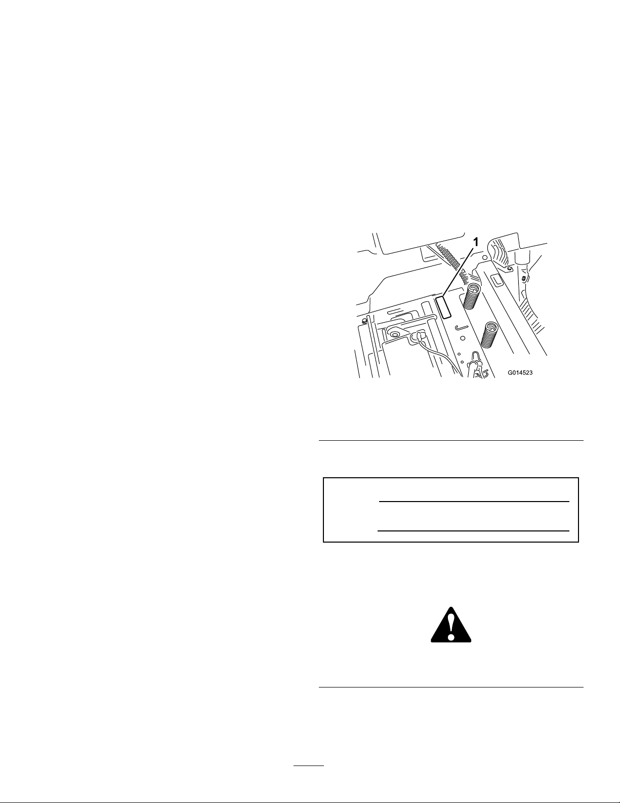
yourproductready .Figure1identiesthelocationofthe
modelandserialnumbersontheproduct.Writethenumbers
inthespaceprovided.
Figure1
Undertheseat
1.Modelandserialnumberplate
Writetheproductmodelandserialnumbersinthespace
below:
ModelNo.
SerialNo.
Thismanualidentiespotentialhazardsandhassafety
messagesidentiedbythesafetyalertsymbol(Figure2),
whichsignalsahazardthatmaycauseseriousinjuryordeath
ifyoudonotfollowtherecommendedprecautions.
Figure2
1.Safetyalertsymbol.
©2012—TheToro®Company
8111LyndaleAvenueSouth
Bloomington,MN55420
Thismanualusestwootherwordstohighlightinformation.
Importantcallsattentiontospecialmechanicalinformation
andNoteemphasizesgeneralinformationworthyofspecial
attention.
Contactusatwww.T oro.com.
2
PrintedintheUSA.
AllRightsReserved
Page 3

Contents
Introduction..................................................................2
Safety...........................................................................4
SafeOperationPracticesforRide-on(riding)
RotaryLawnMowerMachines...............................4
SafeOperatingPractices...........................................4
ToroRidingMowerSafety........................................5
Model74386...........................................................6
Model74387...........................................................6
SlopeIndicator.......................................................7
SafetyandInstructionalDecals.................................8
ProductOverview.........................................................14
Controls...............................................................15
Operation....................................................................16
ThinkSafetyFirst...................................................16
BeforeStarting.......................................................18
StartingtheEngine.................................................19
OperatingtheBlades...............................................20
TestingtheSafetyInterlockSystem...........................20
StoppingtheEngine...............................................21
Driving.................................................................21
StoppingtheMachine.............................................22
AdjustingtheHeightofCut.....................................23
AdjustingtheAnti-ScalpRollers(For42inch
MowerDecks)....................................................23
AdjustingtheAnti-ScalpRollers(For50inch
MowerDecks)....................................................23
PositioningtheSeat................................................24
AdjustingtheMotionControlLevers........................24
PushingtheMachinebyHand..................................25
GrassDeector......................................................26
ConvertingtoSideDischarge(ForModelswith42
InchDecks).......................................................26
ConvertingtoSideDischarge(ForModelswith50
InchDecks).......................................................27
OperatingTips......................................................29
Maintenance.................................................................30
RecommendedMaintenanceSchedule(s)......................30
PremaintenanceProcedures........................................31
RaisingtheSeat......................................................31
Lubrication...............................................................31
GreasingtheBearings.............................................31
EngineMaintenance..................................................32
ServicingtheAirCleaner.........................................32
ServicingtheEngineOil..........................................32
ServicingtheSparkPlug..........................................34
CleaningtheCoolingSystem....................................35
FuelSystemMaintenance...........................................36
ReplacingtheIn-lineFuelFilter................................36
ElectricalSystemMaintenance....................................37
ChargingtheBattery...............................................37
ServicingtheFuses.................................................38
DriveSystemMaintenance.........................................39
CheckingtheTirePressure......................................39
ReleasingtheElectricBrake.....................................39
MowerMaintenance...................................................40
ServicingtheCuttingBlades.....................................40
LevelingtheMowerDeck........................................42
RemovingtheMower..............................................45
MowerBeltMaintenance.........................................46
InstallingtheMower...............................................47
ReplacingtheGrassDeector..................................47
Cleaning...................................................................48
WashingtheUndersideoftheMower........................48
Storage........................................................................49
CleaningandStorage..............................................49
Troubleshooting...........................................................50
Schematics...................................................................52
3
Page 4

Safety
SafeOperationPracticesfor
Ride-on(riding)RotaryLawn
MowerMachines
ThismachinemeetsorexceedsEuropeanStandardsin
effectatthetimeofproduction.However,improperuseor
maintenancebytheoperatororownercanresultininjury.
Toreducethepotentialforinjury,complywiththesesafety
instructionsandalwayspayattentiontothesafetyalert
symbol,whichmeansCAUTION,WARNING,orDANGER
-“personalsafetyinstruction.”Failuretocomplywiththe
instructionmayresultinpersonalinjuryordeath.
SafeOperatingPractices
ThefollowinginstructionsarefromtheENstandardEN
836:1997.
Thisproductiscapableofamputatinghandsandfeetand
throwingobjects.Alwaysfollowallsafetyinstructionsto
avoidseriousinjuryordeath.
Training
•Readtheinstructionscarefully.Befamiliarwiththe
controlsandtheproperuseoftheequipment.
Preparation
•Whilemowing,alwayswearsubstantialfootwearandlong
trousers.Donotoperatetheequipmentwhenbarefoot
orwearingopensandals.
•Thoroughlyinspecttheareawheretheequipmentisto
beusedandremoveallobjectswhichmaybethrownby
themachine.
•Warning-Fuelishighlyammable.
–Storefuelincontainersspecicallydesignedforthis
purpose.
–Refueloutdoorsonlyanddonotsmokewhile
refuelling.
–Addfuelbeforestartingtheengine.Neverremove
thecapofthefueltankoraddfuelwhiletheengineis
runningorwhentheengineishot.
–Iffuelisspilled,donotattempttostarttheengine
butmovethemachineawayfromtheareaofspillage
andavoidcreatinganysourceofignitionuntilfuel
vaporshavedissipated.
–Replaceallfueltanksandcontainercapssecurely.
•Replacefaultysilencers.
•Beforeusing,alwaysvisuallyinspecttoseethattheblades,
bladeboltsandcutterassemblyarenotwornordamaged.
Replacewornordamagedbladesandboltsinsetsto
preservebalance.
•Onmulti-bladedmachines,takecareasrotatingoneblade
cancauseotherbladestorotate.
•Neverallowchildrenorpeopleunfamiliarwiththese
instructionstousethelawnmower.Localregulationscan
restricttheageoftheoperator.
•Nevermowwhilepeople,especiallychildren,orpetsare
nearby.
•Keepinmindthattheoperatororuserisresponsiblefor
accidentsorhazardsoccurringtootherpeopleortheir
property.
•Donotcarrypassengers.
•Alldriversshouldseekandobtainprofessionaland
practicalinstruction.Suchinstructionshouldemphasize:
–theneedforcareandconcentrationwhenworking
withride-onmachines;
–controlofaride-onmachineslidingonaslopewill
notberegainedbytheapplicationofthebrake.The
mainreasonsforlossofcontrolare:
◊insufcientwheelgrip;
◊beingdriventoofast;
◊inadequatebraking;
◊thetypeofmachineisunsuitableforitstask;
◊lackofawarenessoftheeffectofground
conditions,especiallyslopes;
◊incorrecthitchingandloaddistribution.
Operation
•Bealert,slowdownandusecautionwhenmakingturns.
Lookbehindandtothesidebeforechangingdirections.
•Donotoperatetheengineinaconnedspacewhere
dangerouscarbonmonoxidefumescancollect.
•Mowonlyindaylightoringoodarticiallight.
•Beforeattemptingtostarttheengine,disengageallblade
attachmentclutchesandshiftintoneutral.
•Donotuseonslopesofmorethan15degrees.
•Rememberthereisnosuchthingasasafeslope.Travel
ongrassslopesrequiresparticularcare.Toguardagainst
overturning:
–donotstoporstartsuddenlywhengoingupor
downhill;
–uselowspeedsonslopesandduringtightturns;
–stayalertforhumpsandhollowsandotherhidden
hazards;
•Usecarewhenpullingloads.
–Useonlyapproveddrawbarhitchpoints.
–Limitloadstothoseyoucansafelycontrol.
–Donotturnsharply.Usecarewhenreversing.
•Watchoutfortrafcwhencrossingornearroadways.
•Stopthebladesrotatingbeforecrossingsurfacesother
thangrass.
4
Page 5

•Whenusinganyattachments,neverdirectdischargeof
materialtowardbystandersnorallowanyonenearthe
machinewhileinoperation.
•Neveroperatethemachinewithdamagedguardsor
withoutsafetyprotectivedevicesinplace.
•Donotchangetheenginegovernorsettingsoroverspeed
theengine.Operatingtheengineatexcessivespeedcan
increasethehazardofpersonalinjury.
•Beforeleavingtheoperator'sposition:
–disengagethepowertake-offandlowerthe
attachments;
–changeintoneutralandsettheparkingbrake;
–stoptheengineandremovethekey.
•Disengagedrivetoattachments,stoptheengine,and
disconnectthesparkplugwire(s)orremovetheignition
key
–beforeclearingblockagesoruncloggingchute;
–beforechecking,cleaningorworkingonthelawn
mower;
–afterstrikingaforeignobject.Inspectthelawn
mowerfordamageandmakerepairsbeforerestarting
andoperatingtheequipment;
–ifthemachinestartstovibrateabnormally(check
immediately).
•Disengagedrivetoattachmentswhentransportingornot
inuse.
•Stoptheengineanddisengagedrivetoattachment
–beforerefuelling;
–beforeremovingthegrasscatcher;
–beforemakingheightadjustmentunlessadjustment
canbemadefromtheoperator'sposition.
•Reducethethrottlesettingduringenginerun-outand,if
theengineisprovidedwithashut-offvalve,turnthefuel
offattheconclusionofmowing.
•Lightningcancausesevereinjuryordeath.Iflightning
isseenorthunderisheardinthearea,donotoperate
themachine;seekshelter.
MaintenanceandStorage
•Keepallnuts,boltsandscrewstighttobesurethe
equipmentisinsafeworkingcondition.
•Neverstoretheequipmentwithfuelinthetankinsidea
buildingwherefumescanreachanopenameorspark.
•Allowtheenginetocoolbeforestoringinanyenclosure.
•Toreducetherehazard,keeptheengine,silencer,
batterycompartmentandfuelstorageareafreeofgrass,
leaves,orexcessivegrease.
•Checkthegrasscatcherfrequentlyforwearor
deterioration.
•Replacewornordamagedpartsforsafety .
•Ifthefueltankhastobedrained,thisshouldbedone
outdoors.
•Whenmachineistobeparked,storedorleftunattended,
lowerthecuttingmeans.
ToroRidingMowerSafety
ThefollowinglistcontainssafetyinformationspecictoToro
productsorothersafetyinformationthatyoumustknowthat
isnotincludedintheCENstandard.
•Engineexhaustcontainscarbonmonoxide,whichisan
odorless,deadlypoisonthatcankillyou.Donotrun
engineindoorsorinanenclosedarea.
•Keephands,feet,hairandlooseclothingawayfrom
attachmentdischargearea,undersideofmowerandany
movingpartswhileengineisrunning.
•Donottouchequipmentorattachmentpartswhichmay
behotfromoperation.Allowtocoolbeforeattempting
tomaintain,adjust,orservice.
•Batteryacidispoisonousandcancauseburns.Avoid
contactwithskin,eyesandclothing.Protectyourface,
eyes,andclothingwhenworkingwithabattery.
•Batterygasescanexplode.Keepcigarettes,sparks,and
amesawayfrombattery.
•UseonlygenuineTororeplacementpartstoensurethat
originalstandardsaremaintained.
•UseonlyT oro-approvedattachments.
SlopeOperation
•Donotmowslopesgreaterthan15degrees.
•Donotmowneardrop-offs,ditches,steepbanks,or
water.Wheelsdroppingoveredgescancauserollovers,
whichmayresultinseriousinjury,death,ordrowning.
•Donotmowslopeswhengrassiswet.Slippery
conditionsreducetractionandcouldcauseslidingand
lossofcontrol.
•Donotmakesuddenturnsorrapidspeedchanges.
•Useawalkbehindmowerand/orahandtrimmernear
drop-offs,ditches,steepbanks,orwater.
•Reducespeedanduseextremecautiononslopes.
•Removeormarkobstaclessuchasrocks,treelimbs,etc.
frommowingarea.Tallgrasscanhideobstacles.
•Watchforditches,holes,rocksdips,andrisesthatchange
theoperatingangle,asroughterraincouldoverturnthe
machine.
•Avoidsuddenstartswhenmowinguphillbecausethe
mowermaytipbackwards.
•Beawarethatlossoftractionmayoccurgoingdownhill.
Weighttransfertothefrontwheelsmaycausedrive
wheelstoslipandcauselossofbrakingandsteering.
•Alwaysavoidsuddenstartingorstoppingonaslope.
Iftireslosetraction,disengagethebladesandproceed
slowlyofftheslope.
5
Page 6

•Followthemanufacturer'srecommendationsforwheel
weightsorcounterweightstoimprovestability.
•Useextremecarewithgrasscatchersorotherattachments.
Thesecanchangethestabilityofthemachineandcause
lossofcontrol.
Soundpowerlevelwasdeterminedaccordingtothe
proceduresoutlinedinISO11094.
Vibration
Measuredvibrationlevelforrighthand=1.9m/s
2
Model74386
SoundPressure
Thisunithasasoundpressurelevelattheoperator’searof89
dBA,whichincludesanUncertaintyValue(K)of1dBA.
Soundpowerlevelwasdeterminedaccordingtothe
proceduresoutlinedinEN836.
SoundPower
Thisunithasaguaranteedsoundpowerlevelof100dBA,
whichincludesanUncertaintyValue(K)of1dBA.
Soundpowerlevelwasdeterminedaccordingtothe
proceduresoutlinedinISO11094.
Vibration
Measuredvibrationlevelforrighthand=1.3m/s
Measuredvibrationlevelforlefthand=1.3m/s
UncertaintyValue(K)=0.7m/s
2
2
2
Measuredvibrationlevelforlefthand=2.8m/s
UncertaintyValue(K)=1.4m/s
Measuredvaluesweredeterminedaccordingtotheprocedures
outlinedinEN836.
2
WholeBodyVibration
Measuredvibrationlevel=0.37m/s
UncertaintyValue(K)=0.19m/s
Measuredvaluesweredeterminedaccordingtotheprocedures
outlinedinEN836(Riding&Stand-Ons).
2
2
2
Measuredvaluesweredeterminedaccordingtotheprocedures
outlinedinEN836.
WholeBodyVibration
Measuredvibrationlevel=0.33m/s
UncertaintyValue(K)=0.16m/s
Measuredvaluesweredeterminedaccordingtotheprocedures
outlinedinEN836(Riding&Stand-Ons).
2
2
Model74387
SoundPressure
Thisunithasasoundpressurelevelattheoperator’searof94
dBA,whichincludesanUncertaintyValue(K)of1dBA.
Soundpowerlevelwasdeterminedaccordingtothe
proceduresoutlinedinEN836.
SoundPower
Thisunithasaguaranteedsoundpowerlevelof105dBA,
whichincludesanUncertaintyValue(K)of1dBA.
6
Page 7
SlopeIndicator
G011841
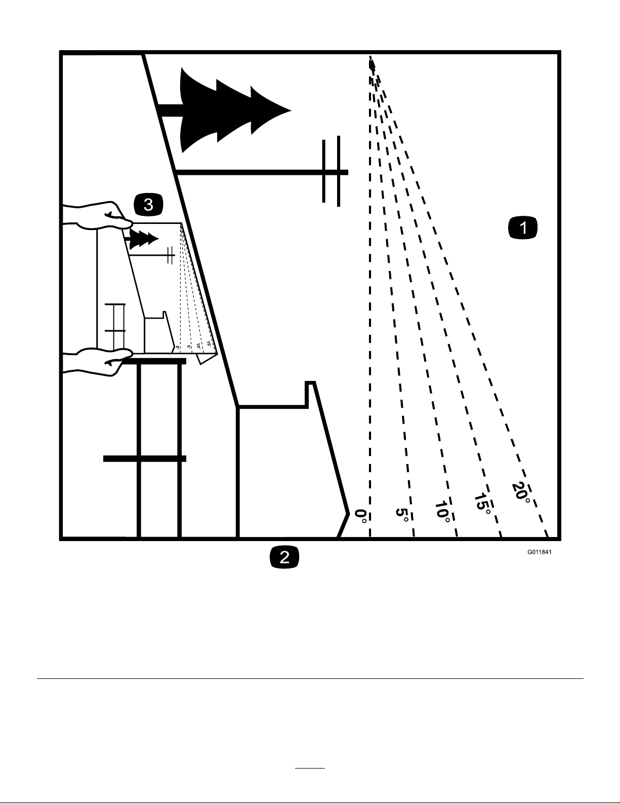
Figure3
Thispagemaybecopiedforpersonaluse.
1.Themaximumslopeyoucansafelyoperatethemachineonis15degrees.Usetheslopecharttodeterminethedegreeofslope
ofhillsbeforeoperating.Donotoperatethismachineonaslopegreaterthan15degrees.Foldalongtheappropriateline
tomatchtherecommendedslope.
2.Alignthisedgewithaverticalsurface,atree,building,fencepole,etc.
3.Exampleofhowtocompareslopewithfoldededge.
7
Page 8
SafetyandInstructional
Decals
Safetydecalsandinstructionsareeasilyvisibletotheoperatorandarelocatednearanyareaofpotential
danger.Replaceanydecalthatisdamagedorlost.
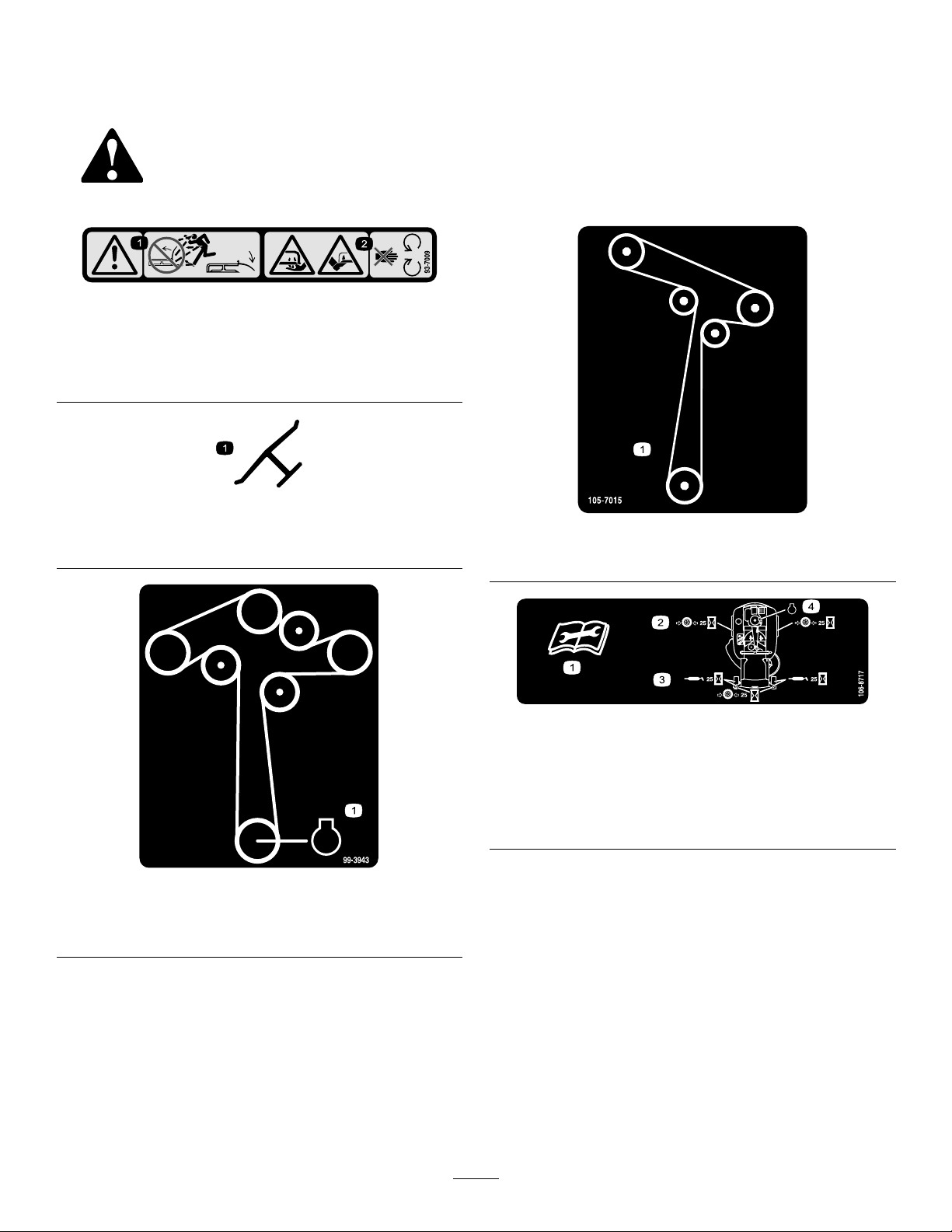
93-7009
1.Warning—don'toperatethemowerwiththedeectorupor
removed;keepthedeectorinplace.
2.Cutting/dismembermenthazardofhandorfoot,mower
blade—stayawayfrommovingparts.
Manufacturer'sMark
1.Indicatesthebladeisidentiedasapartfromtheoriginal
machinemanufacturer.
105-7015
ForModelswith42InchDecks
106-8717
1.Readtheinstructionsbeforeservicingorperforming
maintenance.
2.Checktirepressureevery25operatinghours.
3.Greaseevery25operatinghours.
4.Engine
99-3943
ForModelswith50InchDecks
1.Engine
8
Page 9
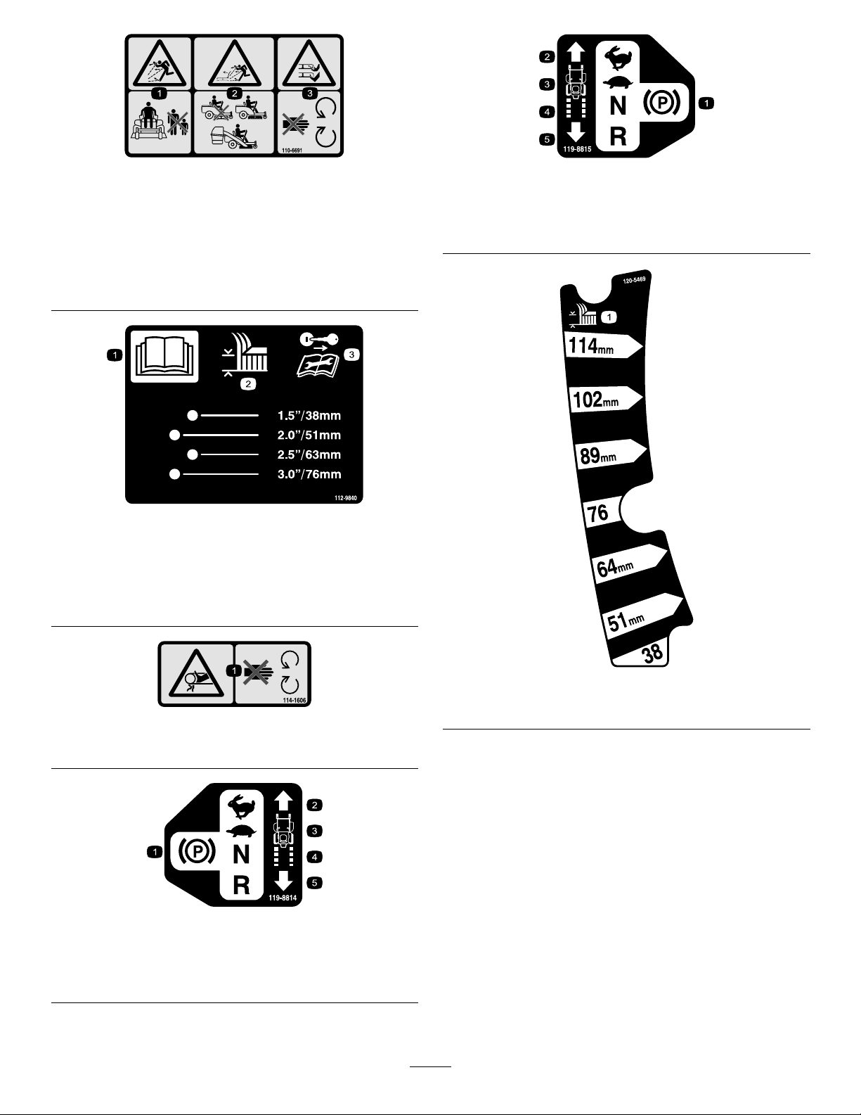
110-6691
119-8815
1.Thrownobjecthazard—keepbystandersasafedistance
fromthemachine.
2.Thrownobjecthazard,mower—donotoperatewithoutthe
deector,dischargecover,orgrasscollectionsystemin
place.
3.Cutting/dismembermentofhandorfoot—stayawayfrom
movingparts.
112-9840
1.ReadtheOperator's
Manual.
2.Heightofcut
3.Removetheignitionkey
andreadtheinstructions
beforeservicingor
performingmaintenance.
1.Parkingposition4.Neutral
2.Fast5.Reverse
3.Slow
114-1606
1.Entanglementhazard,belt—keepallguardsinplace.
119-8814
1.Parkingposition4.Neutral
2.Fast5.Reverse
3.Slow
120-5469
1.Height-of-cut
9
Page 10
BatterySymbols
Someorallofthesesymbolsareonyourbattery
1.Explosionhazard
2.Nore,opename,or
smoking.
3.Causticliquid/chemical
burnhazard
4.Weareyeprotection9.Flusheyesimmediately
5.ReadtheOperator's
Manual.
6.Keepbystandersasafe
distancefromthebattery .
7.Weareyeprotection;
explosivegasescan
causeblindnessandother
injuries
8.Batteryacidcancause
blindnessorsevereburns.
withwaterandgetmedical
helpfast.
10.Containslead;donot
discard.
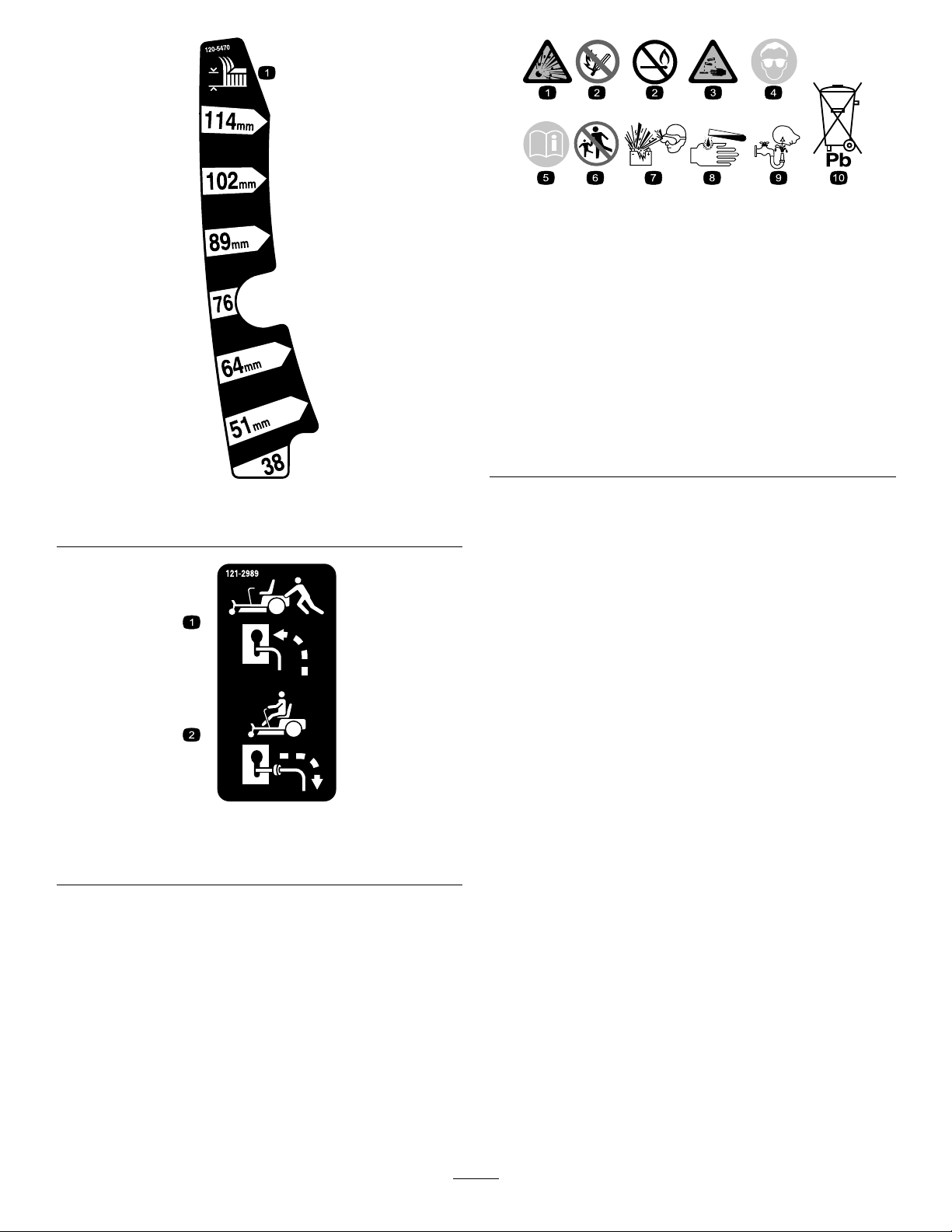
120-5470
1.Height-of-cut
1.Bypassleverpositionfor
pushingthemachine
121-2989
2.Bypassleverpositionfor
operatingthemachine
10
Page 11
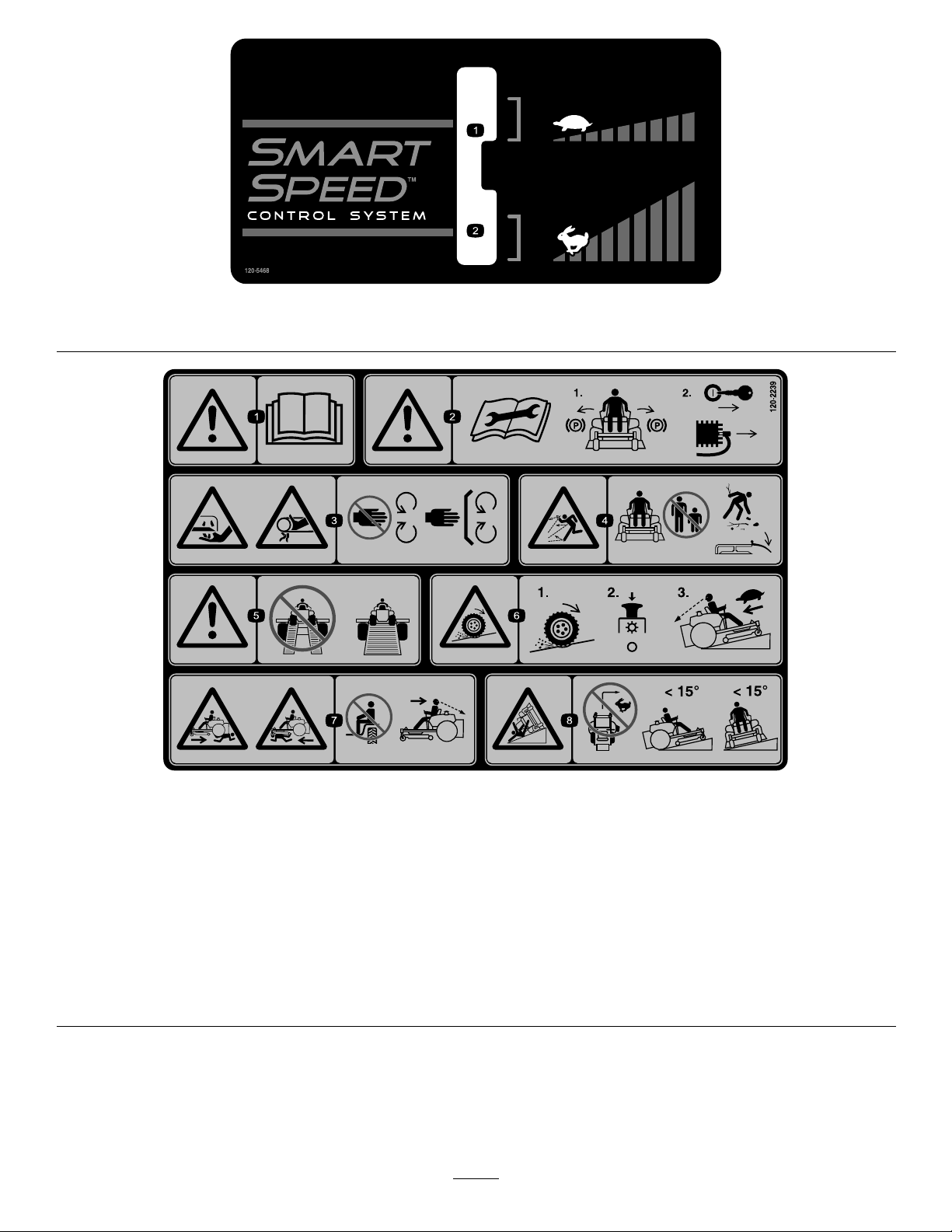
120-5468
1.Slowspeed
2.Fastspeed
120-2239
1.Warning—readtheOperator'sManual.5.Warning—donotusesplitramps,useafullrampswhen
2.Warning—readtheinstructionsbeforeservicingorperforming
maintenance;movethemotioncontrolleverstothepark
(brake)position,removetheignitionkeyanddisconnectthe
sparkplugwire.
3.Cutting/dismembermenthazard,mowerblade;entanglement
hazard,belt—stayawayfrommovingparts,keepallguards
andshieldsinplace.
4.Thrownobjecthazard—keepbystandersasafedistancefrom
themachine,pickupdebrisbeforeoperating,keepdeector
inplace.
transportingmachine.
6.Lossoftraction/controlhazard,slopes—lossoftraction/control
onaslope,disengagethebladecontrolswitch(PTO),
proceedofftheslopeslowly .
7.Crushing/dismembermenthazardofbystanders,reversing;
crushing/dismembermenthazardofbystanders—donotcarry
passengers,lookbehindanddownwhenreversing.
8.Tippinghazard—donotmowslopesgreaterthan15degrees,
avoidsuddenandsharpturnswhileonslopes.
11
Page 12
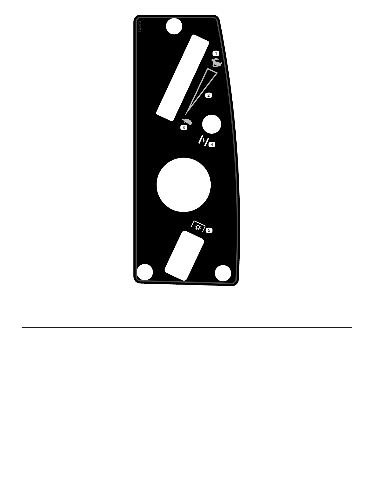
121-0772
1.Fast
2.Continuousvariablesetting5.Powertake-off(PTO),Bladecontrolswitch
3.Slow
4.Choke
12
Page 13
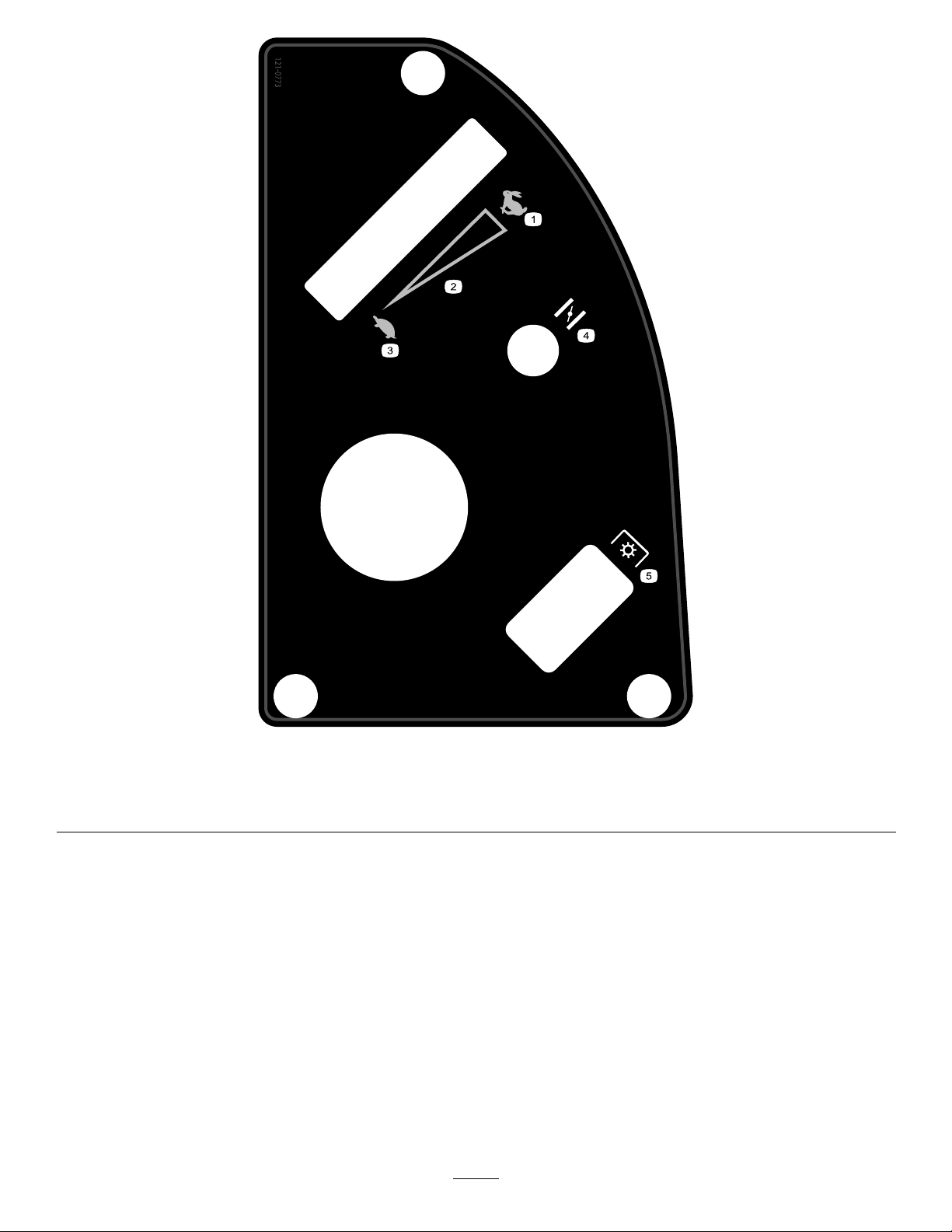
121-0773
1.Fast
2.Continuousvariablesetting5.Powertake-off(PTO),Bladecontrolswitch
3.Slow
4.Choke
13
Page 14
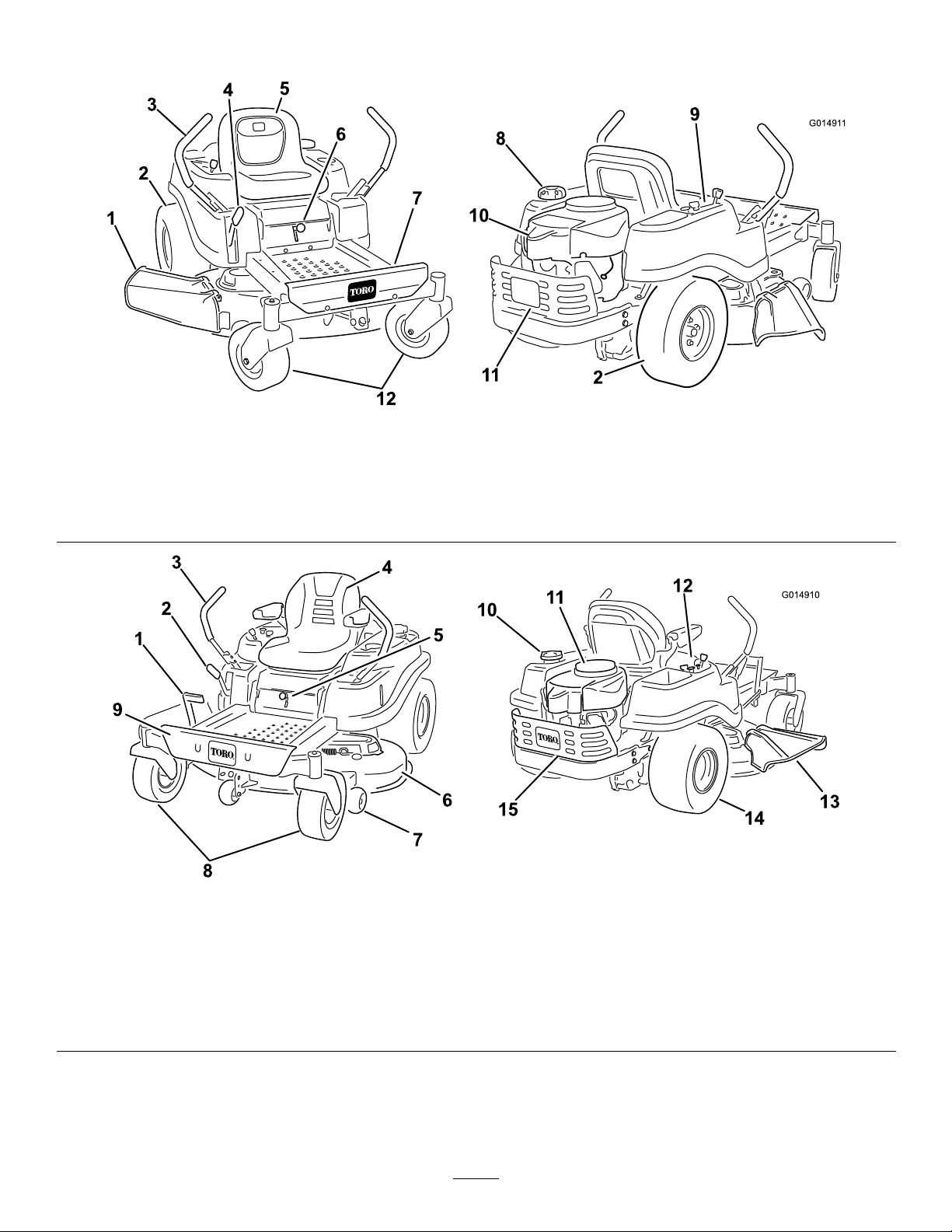
ProductOverview
G01491 1
1
2
3
4
5
6
7
8
9
10
11
2
12
G014910
1
2
3
4
5
6
7
8
9
10
11
12
13
14
15
Figure4
Modelswith42inchdecks
1.Deector4.Heightofcutlever
2.Reardrivewheel
3.Motioncontrollevers
1.Footassistlever
2.Heightofcutlever
3.Motioncontrollevers7.Anti-scalproller11.Engine15.Engineguard
4.Operatorseat(armrests
optional)
5.Operatorseat
6.SmartSpeed™lever9.Controlpanel
Modelswith50inchdecks
5.SmartSpeed™lever
6.Mowerdeck
8.Frontcasterwheel
7.Footrest10.Engine
8.Fueltankcap11.Engineguard
Figure5
9.Footrest
10.Gastankcap
12.Controlpanel
12.Frontcasterwheel
13.Deector
14.Reardrivewheel
14
Page 15
Controls
G014475
1
G014521
1
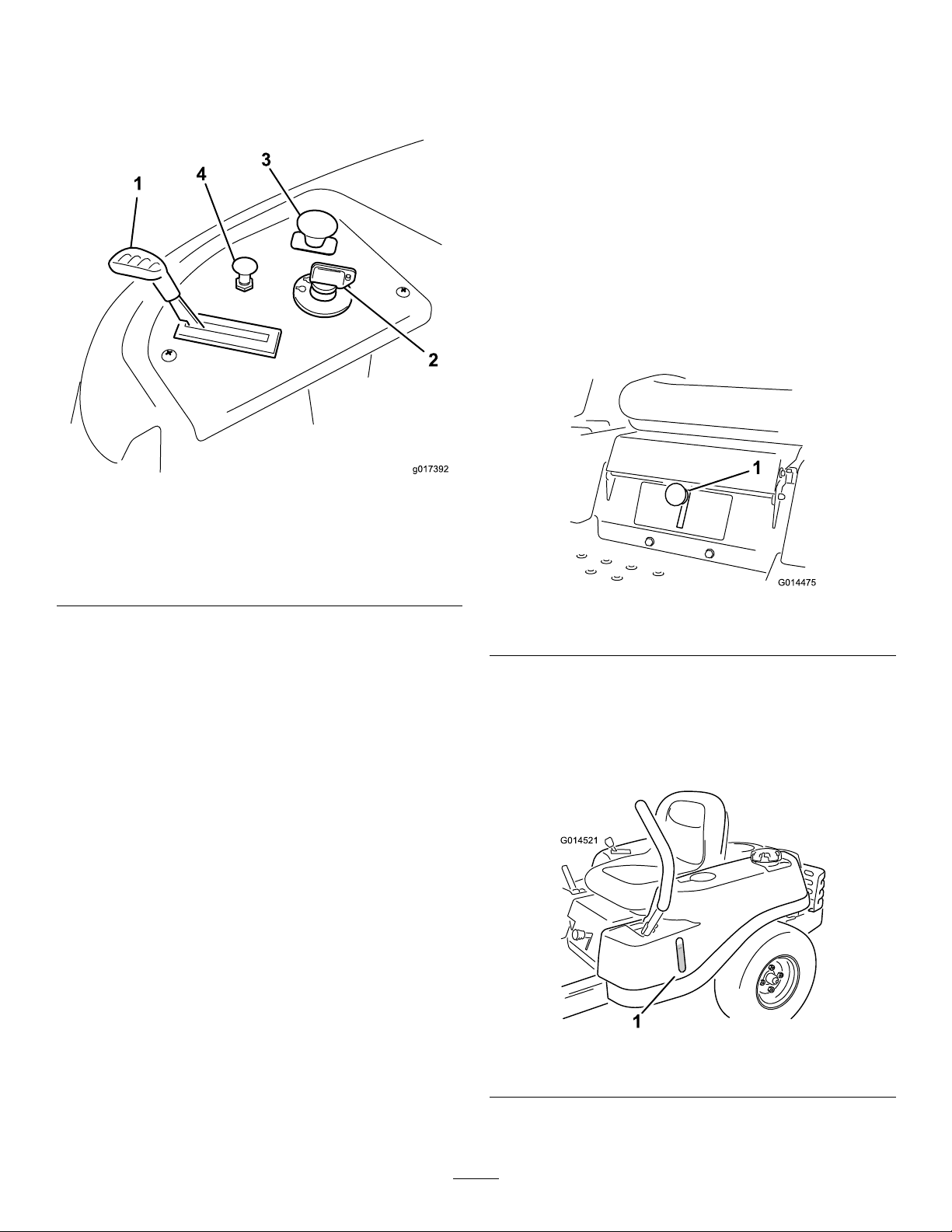
BecomefamiliarwithallofthecontrolsinFigure4,Figure5,
andFigure6beforeyoustarttheengineandoperatethe
machine.
Figure6
ControlPanel
MotionControlLeversandPark
Position
Themotioncontrolleversarespeedsensitivecontrolsof
independentwheelmotors.Movingaleverforwardor
backwardturnsthewheelonthesamesideforwardorin
reverse;wheelspeedisproportionaltotheamountthelever
ismoved.Movethecontrolleversoutwardfromthecenter
totheparkpositionandexitthemachine(Figure17).Always
positionthemotioncontrolleversintotheparkposition
whenyoustopthemachineorleaveitunattended.
SmartSpeed™ControlSystemLever
TheSmartSpeed™ControlSystemlever,locatedbelowthe
operatingposition,givestheoperatorachoicetodrivethe
machineattwospeedranges,highandlow(Figure7).
1.Throttle3.Bladecontrolswitch
2.Ignitionswitch
(powertake-off)
4.Choke
IgnitionSwitch
Theignitionswitchhasthreepositions,Off,RunandStart.
ThekeywillturntoStartandmovebacktoRunuponrelease.
TurningthekeytotheOffpositionwillstoptheengine;
however,alwaysremovethekeywhenleavingthemachine
topreventsomeonefromaccidentallystartingtheengine
(Figure6).
ThrottleControl
Thethrottlecontrolstheenginespeedandithasacontinuous
variablesettingfromSlowtoFast(Figure6).
ChokeControl
PullupontheChokecontroluntilitstopstochokethe
engine(Figure6).PushdownontheChokecontrolfor
normalengineoperation
Figure7
1.Smartspeedlever
FuelWindow
Thefuelwindowlocatedonthelefthandsideofthemachine
canbeusedtoverifythepresenceofgasolineinthetank
(Figure8).
BladeControlSwitch(PowerTake-Off)
Thebladecontrolswitch,representedbyapowertake-off
(PTO)symbol,engagesanddisengagespowertothemower
blades(Figure6).
Figure8
1.Fuelpresencewindow
15
Page 16

Height-of-CutLever
Theheightofcutleverallowstheoperatortolowerand
raisethedeckfromtheseatedposition.Whentheleveris
movedup,towardtheoperatorthedeckisraisedfromthe
groundandwhenmoveddown,awayfromtheoperatoritis
loweredtowardtheground.Onlyadjusttheheightofcut
whilemachineisnotmoving(Figure21).
Operation
Note:Determinetheleftandrightsidesofthemachine
fromthenormaloperatingposition.
ThinkSafetyFirst
OperatingSafety
Pleasecarefullyreadallofthesafetyinstructionsanddecals
inthesafetysection.Knowingthisinformationcouldhelp
you,yourfamily,petsorbystandersavoidinjury.
DANGER
Mowingonwetgrassorsteepslopescancause
slidingandlossofcontrol.
Wheelsdroppingoveredgescancauserollovers,
whichmayresultinseriousinjury,deathor
drowning.
Alossoftractionisalossofsteeringcontrol.
Toavoidlossofcontrolandpossibilityofrollover:
•Donotmowneardrop-offsornearwater.
•Donotmowslopesgreaterthan15degrees.
•Reducespeedanduseextremecautionon
slopes.
•Whenmowingslopes,graduallyworkfrom
lowertohigherareasontheincline.
•Avoidsuddenturnsorrapidspeedchanges.
•Turnup,intoaninclinewhenchanging
directionsonslopes.Turningdowntheslope
reducestraction.
•Attachmentschangethehandlingcharacteristics
ofthemachine.Useextracautionwhenusing
attachmentswiththemachine.
16
Page 17
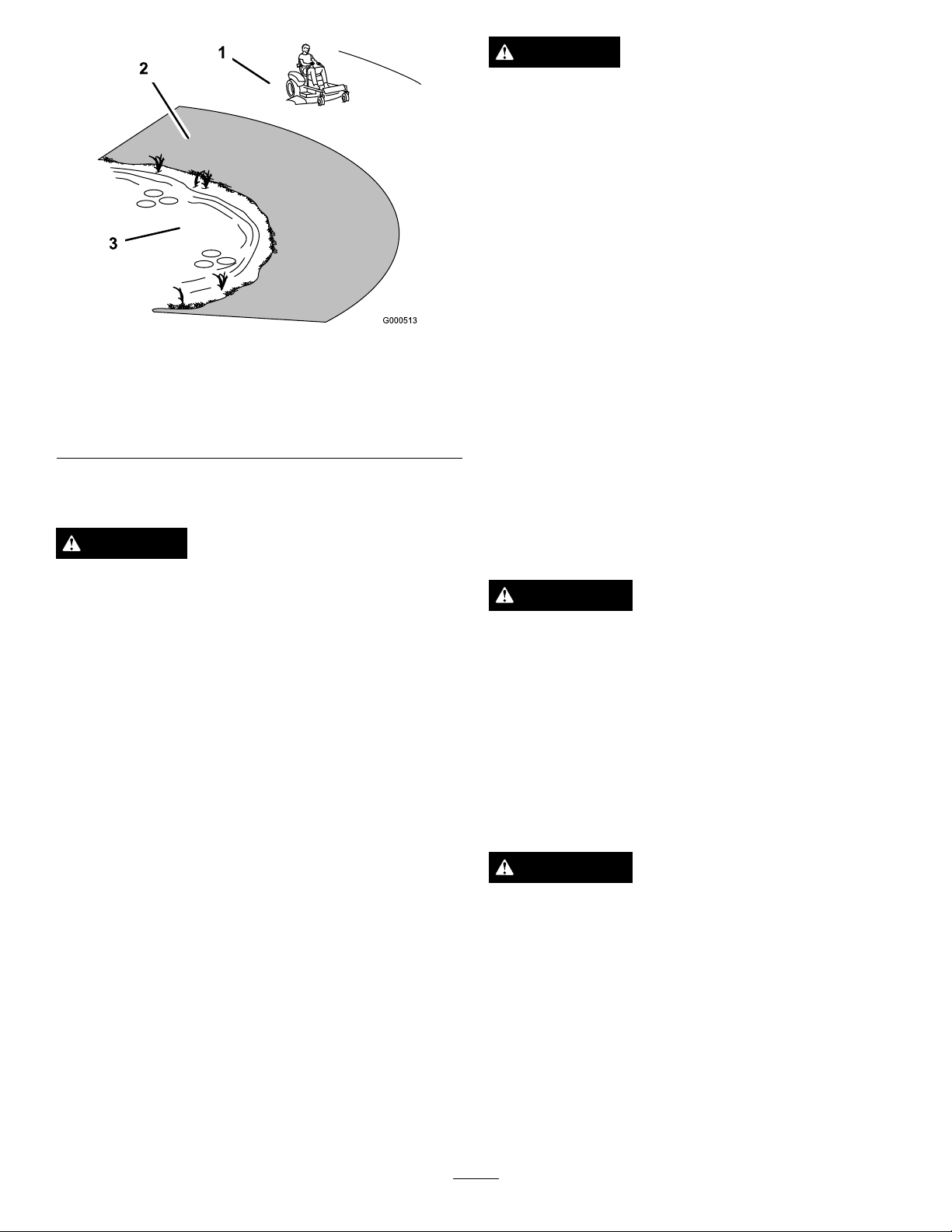
1.SafeZone-usethe
TimeCutterhere
2.Usewalkbehindmower
and/orhandtrimmernear
drop-offsandwater .
FuelSafety
DANGER
Figure9
3.Water
DANGER
Incertainconditionsduringfueling,static
electricitycanbereleasedcausingasparkwhich
canignitethegasolinevapors.Areorexplosion
fromgasolinecanburnyouandothersandcan
damageproperty.
•Alwaysplacegasolinecontainersontheground
awayfromyourvehiclebeforelling.
•Donotllgasolinecontainersinsideavehicleor
onatruckortrailerbedbecauseinteriorcarpets
orplastictruckbedlinersmayinsulatethe
containerandslowthelossofanystaticcharge.
•Whenpractical,removegas-poweredequipment
fromthetruckortrailerandrefueltheequipment
withitswheelsontheground.
•Ifthisisnotpossible,thenrefuelsuch
equipmentonatruckortrailerfromaportable
container,ratherthanfromagasolinedispenser
nozzle.
•Ifagasolinedispensernozzlemustbeused,
keepthenozzleincontactwiththerimofthe
fueltankorcontaineropeningatalltimesuntil
fuelingiscomplete.
Incertainconditions,gasolineisextremely
ammableandhighlyexplosive.Areorexplosion
fromgasolinecanburnyouandothersandcan
damageproperty.
•Fillthefueltankoutdoors,inanopenarea,
whentheengineiscold.Wipeupanygasoline
thatspills.
•Neverllthefueltankinsideanenclosedtrailer.
•Donotllthefueltankcompletelyfull.Add
gasolinetothefueltankuntilthefuelreaches
thebaseofthellerneck.Thisemptyspacein
thetankallowsgasolinetoexpand.
•Neversmokewhenhandlinggasoline,andstay
awayfromanopenameorwheregasoline
fumesmaybeignitedbyaspark.
•Storegasolineinanapprovedcontainerand
keepitoutofthereachofchildren.Neverbuy
morethana30-daysupplyofgasoline.
•Donotoperatewithoutentireexhaustsystemin
placeandinproperworkingcondition.
WARNING
Gasolineisharmfulorfatalifswallowed.Long-term
exposuretovaporscancauseseriousinjuryand
illness.
•Avoidprolongedbreathingofvapors.
•Keepfaceawayfromnozzleandgastankor
conditioneropening .
•Keepgasawayfromeyesandskin.
UnderstandingtheSafetyInterlock
System
WARNING
Ifsafetyinterlockswitchesaredisconnectedor
damagedthemachinecouldoperateunexpectedly
causingpersonalinjury.
•Donottamperwiththeinterlockswitches.
•Checktheoperationoftheinterlockswitches
dailyandreplaceanydamagedswitchesbefore
operatingthemachine.
Thesafetyinterlocksystemisdesignedtopreventtheengine
fromstartingunless:
•Thebladesaredisengaged.
•Themotioncontrolleversareintheparkposition.
17
Page 18

Thesafetyinterlocksystemalsoisdesignedtostoptheengine
G014474
1
2
3
4
5
6
G014895
1
2
3
4
wheneverthecontrolleversareoutoftheparkpositionand
yourisefromtheseat.
BeforeStarting
RecommendedFuel
1.Forbestresults,useonlyclean,fresh,unleadedgasoline
withanoctaneratingof87orhigher((R+M)/2rating
method).
2.Oxygenatedfuelwithupto10%ethanolor15%
MTBEbyvolumeisacceptable.
3.DoNotuseethanolblendsofgasoline(suchasE15
orE85)withmorethan10%ethanolbyvolume.
Performanceproblemsand/orenginedamagemay
resultwhichmaynotbecoveredunderwarranty.
4.DoNotusegasolinecontainingmethanol.
5.DoNotstorefueleitherinthefueltankorfuel
containersoverthewinterunlessafuelstabilizeris
used.
6.DoNotaddoiltogasoline.
2.Slowlyaddregular,unleadedgasolineuntilthefuel
reachesthebaseofthellerneck(Figure10).
Figure10
1.Fueltankcap
2.Fillopening5.Fuelwindow
3.Fillerneck
4.Baseofllerneck,DO
NOTFILLP ASTHERE
UsingStabilizer/Conditioner
Useafuelstabilizer/conditionerinthemachinetoprovide
thefollowingbenets:
•Keepsgasolinefreshduringstorageof90daysorless.
Forlongerstorageitisrecommendedthatthefueltank
bedrained.
•Cleanstheenginewhileitruns.
•Eliminatesgum-likevarnishbuildupinthefuelsystem,
whichcauseshardstarting.
Addthecorrectamountofgasstabilizer/conditionertothe
gas.
Note:Afuelstabilizer/conditionerismosteffectivewhen
mixedwithfreshgasoline.Tominimizethechanceofvarnish
depositsinthefuelsystem,usefuelstabilizeratalltimes.
FillingtheFuelTank
Makesuretheengineisshutoffandthemotioncontrolsare
intheparkposition.Tankmaximumcapacityis2.9gallons.
Important:DoNotoverllfueltank.Fillthefueltank
tothebottomofthellerneck.Theemptyspaceinthe
tankallowsthefueltoexpand.Overllingmayresult
infuelleakageordamagetotheengineoremissions
system.
1.Cleanaroundthefueltankcapandremovethecap.
Figure11
1.Fillopening3.Fuel
2.Baseofllerneck,DO
NOTFILLP ASTHERE
4.Emptyspaceforfuel
expansion.
Important:DoNotoverllfueltank.Fillthe
fueltanktothebottomofthellerneck.The
emptyspaceinthetankallowsthefueltoexpand.
Overllingmayresultinfuelleakageordamage
totheengine.
3.Installthefueltankcapsecurelyandtightenuntilit
“clicks”.Wipeupanygasolinethatmayhavespilled.
CheckingtheEngineOilLevel
Beforeyoustarttheengineandusethemachine,checktheoil
levelintheenginecrankcase;refertoCheckingtheOilLevel
intheEngineMaintenancesection.
Note:Youcanusethefuelwindowtoverifythe
presenceofgasolinebeforellingthetank(
Figure10).
18
Page 19

StartingtheEngine
1.Sitdownontheseatandmovethemotioncontrols
outwardtotheparkposition.
2.Disengagethebladesbymovingthebladecontrol
switchtoOff(Figure12)
Figure13
Figure12
1.Controlpanel2.Bladecontrolswitch—Off
position
3.PullupontheChokecontrolbeforestartingacold
engine(Figure13).
Note:Awarmorhotenginemaynotrequirechoking.
1.Controlpanel4.Continuousvariable
2.Throttle
3.Fast
setting
5.Slow
6.Chokecontrol
4.TurntheignitionkeytoStarttoenergizethestarter.
Whentheenginestarts,releasethekey(Figure14).
Important:Donotengagethestarterformore
than10secondsatatime.Iftheenginefailsto
start,allowa60secondcool-downperiodbetween
attempts.Failuretofollowtheseinstructionscan
damagethestartermotor.
19
Page 20

Figure15
Figure14
1.Controlpanel
2.Ignitionkey—runposition
3.Ignitionkey—startposition
4.Off
5.Aftertheenginestarts,pushdownontheChoke
control(
upontheChokecontrolandlettheenginerunfora
fewseconds.ThenpushdownontheChokecontrol.
Repeatthisasrequired.
Figure14).Iftheenginestallsorhesitates,pull
5.Run
6.Start
7.Chokecontrol
OperatingtheBlades
Thebladecontrolswitch,representedbyapowertake-off
(PTO)symbol,engagesanddisengagespowertothemower
blades.Thisswitchcontrolspowertoanyattachmentsthat
drawpowerfromtheengine,includingthemowerdeckand
cuttingblades.
EngagingtheBlades
1.Controlpanel2.Bladecontrolswitch—On
position
DisengagingtheBlades
PushdownonthebladecontrolswitchtomoveittotheOff
positionanddisengagetheblades(Figure16).
Important:Donotengagethebladeswhenparkedin
tallgrass.Beltorclutchdamagecanoccur.
1.Releasepressureonthemotioncontrolleversand
placethemachineinneutral.
2.MovethethrottletotheFastposition.
Note:Alwaysengagethebladeswiththethrottlein
theFastposition.
3.Pulluponthebladecontrolswitchtomoveittothe
Onpositionandengagetheblades(
Figure15).
Figure16
1.Controlpanel2.Bladecontrolswitch—Off
TestingtheSafetyInterlock System
Testthesafetyinterlocksystembeforeyouusethemachine
eachtime.Ifthesafetysystemdoesnotoperateasdescribed
below,haveanAuthorizedServiceDealerrepairthesafety
systemimmediately.
20
Page 21

1.Whilesittingontheseat,withthecontrolleversinpark
G014475
1
position,andmovethebladecontrolswitchtoOn.Try
startingtheengine;theengineshouldnotcrank.
2.Whilesittingontheseat,movethebladecontrol
switchtoOff.Moveeithermotioncontrollevertothe
center,unlockedposition.Trystartingtheengine;the
engineshouldnotcrank.Repeatwiththeothermotion
controllever.
3.Whilesittingontheseat,movethebladecontrolswitch
toOff,andlockthemotioncontrolleversinthepark
position.Starttheengine.Whiletheengineisrunning,
engagethebladecontrolswitch,andriseslightlyfrom
theseat;theengineshouldstop.
4.Whilesittingontheseat,movethebladecontrolswitch
toOff,andlockthemotioncontrolleversinthepark
position.Starttheengine.Whiletheengineisrunning,
movethemotioncontrolleverstothecenter,unlocked
position,engagethebladecontrolswitch,andrise
slightlyfromtheseat;theengineshouldstop.
StoppingtheEngine
1.Disengagethebladesbymovingthebladecontrol
switchtoOff(Figure16).
Figure17
2.MovethethrottlelevertoFast(Figure13).
3.TurntheignitionkeytoOff(Figure14)andremove
thekey.
Driving
Drivingthemachinebenetsfromanunderstandingof
whatzeroturnradiusmowermeans.Thedrivewheelsturn
independently,poweredbyhydraulicmotorsoneachaxle;
henceonesidecanturninreversewhiletheotherturns
forwardcausingthemachinetospinratherthanturn.This
vastlyimprovesthemachinemaneuverabilitybutmayrequire
someadjustmentiftheoperatorisunfamiliar.
WARNING
Themachinecanspinveryrapidly .Theoperator
maylosecontrolofthemachineandcausepersonal
injuryordamagetothemachine.
•Usecautionwhenmakingturns.
•Slowthemachinedownbeforemakingsharp
turns.
Thethrottlecontrolregulatestheenginespeedasmeasured
inrpm(revolutionsperminute).Placingthethrottlecontrol
intheFastpositioncanbebestforperformance.Formost
applications,operatinginthefullthrottlepositionisdesirable.
1.Park(brake)position
2.Centerunlockposition
3.Forward
4.Backward
UsingtheSmartSpeed™Control
System
TheSmartSpeed™ControlSystemlever,locatedbelowthe
operatingposition(),givestheoperatorachoicetodrivethe
machineattwogroundspeedranges,highandlow.
Figure18
1.Smartspeedlever
Tochangespeeds:
1.Movethemotioncontrolleverstoneutralandoutward
totheparkposition;disengagethebladecontrolswitch.
21
Page 22

WARNING
G008952
G008953
Removingyourhandsfromthemotioncontrol
leverswhilethemachineisinmotioncan
resultinalossofcontrolcausingharmtoyou
orbystanders.
Alwaysstopthemachineandmovethemotion
controlleverstotheparkpositionbefore
adjustingtheSmartSpeed™ControlSystem.
2.Adjustthelevertothedesiredposition.
Forward
1.Movetheleverstothecenter,unlockedposition.
2.Togoforward,slowlypushthemotioncontrollevers
forward(Figure17).
Backward
1.Movetheleverstothecenter,unlockedposition.
2.Togobackward,lookbehindyouanddownas
youslowlypullthemotioncontrolleversrearward
(Figure20).
Figure20
Figure19
Togostraight,applyequalpressuretobothmotion
controllevers(Figure17).
Toturn,releasepressureonthemotioncontrollever
towardthedirectionyouwanttoturn(Figure17).
Thefartheryoumovethemotioncontrolleversin
eitherdirection,thefasterthemachinewillmovein
thatdirection.
Tostop,pullthemotioncontrolleverstoneutral.
Togostraight,applyequalpressuretobothmotion
controllevers(Figure20).
Toturn,releasethepressureonthemotioncontrol
levertowardthedirectionyouwanttoturn.
Tostop,pushthemotioncontrolleverstoneutral.
StoppingtheMachine
Tostopthemachine,movethemotioncontrolleversto
neutralandoutwardtotheparkposition,disengagetheblade
controlswitch,ensurethethrottleisinthefastposition,and
turntheignitionkeytooff.Remembertoremovethekey
fromtheignitionswitch.
WARNING
Childrenorbystandersmaybeinjuredifthey
moveorattempttooperatethemowerwhileitis
unattended.
Alwaysremovetheignitionkeyandmovethe
motioncontrolleversoutwardtotheparkposition
whenleavingthemachineunattended,evenifjust
forafewminutes.
22
Page 23

AdjustingtheHeightofCut
G015319
1
2
3
g019929
1
2
3
4
5
Height-of-cutiscontrolledbytheleverlocatedtotherightof
theoperatingposition(Figure21).
•Upperhole—usethispositionwiththemowerdeck
inthe63mm(2-1/2inch)andbelowheight-of-cut
positions(
Figure22).
•Lowerhole—usethispositionwiththemower
deckinthe76mm(3inch)andaboveheight-of-cut
positions(Figure22).
Figure22
Figure21
1.Height-of-cutlever3.115mm(4.5inch),
2.Height-of-cutpositions
1.Pullupandinwardonthelevertomoveittothe
desiredcuttingposition.
2.Onceatthedesiredcuttingposition,slowlylowerthe
leveruntilitengagestheposition.
Thetransportpositionisthehighestheight-of-cutpositionor
cuttingheight115inch[4.5mm](Figure21).
Transportposition
AdjustingtheAnti-Scalp Rollers(For42inchMower Decks)
Wheneveryouchangetheheight-of-cut,itisrecommended
toadjusttheheightoftheanti-scalprollers.
Note:Adjusttheanti-scalprollerssotherollersdonottouch
thegroundinnormal,atmowingareas.
1.Disengagethebladecontrolswitch(PTO),movethe
2.Stoptheengine,removethekey,andwaitforallmoving
motioncontrolleverstotheneutrallockpositionand
settheparkingbrake.
partstostopbeforeleavingtheoperatingposition.
1.Anti-scalproller4.Upperhole—themower
2.Lowerhole—themower
deckinthe76mm(3inch)
andaboveheight-of-cut
positions
3.FlangeNut
deckinthe63mm
(2-1/2inch)andbelow
height-of-cutpositions
5.Bolt
AdjustingtheAnti-Scalp Rollers(For50inchMower Decks)
Wheneveryouchangetheheight-of-cut,itisrecommended
toadjusttheheightoftheanti-scalprollers.
Note:Adjusttheanti-scalprollerssotherollersdonottouch
thegroundinnormal,atmowingareas.
1.Disengagethebladecontrolswitch(PTO),movethe
motioncontrolleverstotheneutrallockpositionand
settheparkingbrake.
2.Stoptheengine,removethekey,andwaitforallmoving
partstostopbeforeleavingtheoperatingposition.
3.Adjusttheanti-scalprollersasshowninFigure23to
matchtheclosestheight-of-cutposition.
3.Adjusttheanti-scalprollerstooneofthefollowing
positions:
23
Page 24

G010233
1
2
3
4
Figure23
G014477
1
1
G014969
4
1
2
G014970
3
1.Anti-scalproller3.FlangeNut
2.Bolt4.Holespacing
Figure25
AdjustingtheMotionControl
PositioningtheSeat
Theseatcanmoveforwardandbackward.Positiontheseat
whereyouhavethebestcontrolofthemachineandaremost
comfortable.
Modelswith42inchDecks
1.Raisetheseatandloosentheadjustmentboltsjust
enoughthatseatcanmove(Figure24).
Levers
AdjustingtheHeight
Themotioncontrolleverscanbeadjustedhigherorlowerfor
maximumoperatorcomfort.
1.Removethe2boltsholdingthecontrollevertothe
controlarmshaft(Figure26).
2.Movethecontrollevertothenextsetofholes.Secure
theleverwiththe2bolts(Figure26).
Figure26
1.Controlarmshaft3.Slotted,upperhole
2.Controllever
4.Bolt
Figure24
1.Adjustmentbolt
2.Movetheseattothedesiredpositionandtightenthe
bolts.
Modelswith50inchDecks
Whilesittingintheoperator’sposition,raisetheseat
adjustmentleverslightlyandmovetheseatforwardor
backwardtothedesiredposition(Figure25).
3.Repeattheadjustmentfortheoppositecontrollever.
AdjustingtheTilt
Themotioncontrolleverscanbetiltedforeoraftfor
maximumoperatorcomfort.
1.Loosentheupperboltholdingthecontrollevertothe
controlarmshaft.
2.Loosenthelowerboltjustenoughtopivotthecontrol
leverforeoraft(
securethecontrolinthenewposition.
3.Repeattheadjustmentfortheoppositecontrollever.
24
Figure26).Tightenbothboltsto
Page 25

PushingtheMachinebyHand
g017303
1 2
3
ToOperatetheMachine
Important:Alwayspushthemachinebyhand.Never
towthemachinebecausedamagemayoccur.
Thismachinehasanelectricbrakemechanismandtopush
themachinetheignitionkeyneedstobeintheRunposition.
Thebatteryneedstobechargedandfunctioningforthe
electricbraketobedisengage.
ToPushtheMachine
1.Parkthemachineonalevelsurfaceanddisengagethe
bladecontrolswitch.
2.Movethemotioncontrolleversoutwardtopark
position,stoptheengine,andwaitforallmovingparts
tostopbeforeleavingtheoperatingposition.
3.Locatethebypassleversontheframeonbothsidesof
theengine.
4.Movethebypassleversforwardthroughthekeyhole
anddowntolocktheminplaceasshowninFigure
23Figure27.Ensurethisisdoneforeachlever.
5.Movethemotioncontrolleversinwardtotheneutral
positionandturntheignitionkeytotherunposition.
Donotstartthemachine.
Movethebypassleversrearwardthroughthekeyholeand
downtolocktheminplaceasshowninFigure27.Ensure
thisisdoneforeachlever.
Themachineisnowabletobepushedbyhand.
Figure27
1.Bypassleverlocations
2.Leverpositionfor
operatingthemachine
3.Leverpositionforpushing
themachine
6.Whennished,ensurethekeyhasbeenreturnedtothe
Stoppositiontoavoiddrainingthebatterycharge.
Ifthemachinefailstomovetheelectricbrake
maystillbeengaged.Ifnecessarytheelectric
brakecanbereleasedmanually.Refertothe
ReleasingtheElectricBrake(page39)procedureinDrive
Maintenance.
25
Page 26

GrassDeector
G009660
1
2
3
4
5
G005667
1
2
3
Themowerhasahingedgrassdeectorthatdisperses
clippingstothesideanddowntowardtheturf.
DANGER
Withoutthegrassdeector,dischargecover,or
completegrasscatcherassemblymountedin
place,youandothersareexposedtobladecontact
andthrowndebris.Contactwithrotatingmower
blade(s)andthrowndebriswillcauseinjuryor
death.
•Neverremovethegrassdeectorfromthemower
becausethegrassdeectorroutesmaterialdown
towardtheturf.Ifthegrassdeectorisever
damaged,replaceitimmediately .
•Neverputyourhandsorfeetunderthemower.
•Nevertrytocleardischargeareaormower
bladesunlessyoumovethebladecontrolswitch
toOffandrotatetheignitionkeytoOff.Also
removethekeyandpullthewireoffthespark
plug(s).
ConvertingtoSideDischarge (ForModelswith42Inch Decks)
Themowerdeckandmowerbladesshippedwiththismachine
weredesignedforoptimummulchingandsidedischarge
performance.
RemovingtheDischargeCoverforSide
Discharge
1.Parkthemachineonalevelsurfaceanddisengagethe
bladecontrolswitch.
2.Movethemotioncontrolleversoutwardtopark
position,stoptheengine,removethekey,andwaitfor
allmovingpartstostopbeforeleavingtheoperating
position.
Figure28
1.Capnut(1/4inch)
2.Dischargecover5.Removethecover
3.Bolt(1/4x2-1/2inches)
4.Removethedischargecover.
5.Liftupthegrassdeectorandlocatethelocknuton
thedeectorpivotrod.Removetheexistingthinnut
(3/8inch).
6.Installthecutoffbafetotheexposedpivotrod
(
Figure29).Usetheexistingthinnut(3/8inch)to
securethebafetothemower.
Note:Thecutoffbafewasshippedwiththemachine
asaloosepart.
4.Rotatethecoverup
3.Removethe2boltsandnutsthatsecurethedischarge
covertothemower(Figure28).
Figure29
1.Pivotrod
2.Cutoffbafe(originally
shippedwiththemachine)
7.Torquethefastenerto14-18ft-lb(7-9N-m).
8.Lowerthegrassdeectoroverthedischargeopening
26
3.Existingthinnut(3/8inch)
Page 27

Important:Ensurethemowerhasahingedgrass
deectorthatdispersesclippingstothesideand
downtowardtheturf,whileinsidedischarge
mode.
ConvertingtoSideDischarge (ForModelswith50Inch Decks)
InstallingtheDischargeCoverfor
Mulching
1.Parkthemachineonalevelsurfaceanddisengagethe
bladecontrolswitch.
2.Movethemotioncontrolleversoutwardtopark
position,stoptheengine,removethekey,andwaitfor
allmovingpartstostopbeforeleavingtheoperating
position.
3.Liftthegrassdeectorandslidethetabsontopofthe
dischargecoverunderthegrassdeectorretainingrod.
Rotatethedischargecoverdownovertheopening,and
ontothelowerlipofthemower(Figure30).
Themowerdeckandmowerbladesshippedwiththismachine
weredesignedforoptimummulchingandsidedischarge
performance.
RemovingtheRightBafeforSide
Discharge
1.Parkthemachineonalevelsurfaceanddisengagethe
bladecontrolswitch.
2.Movethemotioncontrolleversoutwardtopark
position,stoptheengine,removethekey,andwaitfor
allmovingpartstostopbeforeleavingtheoperating
position.
3.Removetherightmowerblade.RefertotheMower
Maintenancesection.
4.Removethe2knobsandcurvedwashersthatsecure
therightbafetothemowerasshowninFigure31.
Figure30
1.Dischargecover
2.Capnut(1/4inch)
4.Securethedischargecovertothelowerlipofthe
mowerwithtwobolts(1/4x2-1/2inches)andtwocap
nuts(1/4inch)asshownin
Note:Donotovertightenthenuts;thiscoulddistort
thecoverandcausebladecontact.
3.Bolt(1/4x2-1/2inches)
Figure30.
Figure31
1.Knob
2.Curvedwasher
5.Removetherightbafeandlowerthegrassdeector
overthedischargeopeningasshowninFigure32and
Figure31.
3.Bafestudcomingthrough
themower
27
Page 28

G006475
1
2
3
4
1
Figure32
G015321
1
2
3
1.Rightbafe
2.Curvedwasherandknob4.Tab(mustremainoutside
3.Dischargeopening
ofthemower)
6.Installfastenersintotheholesinthetopofthemower
topreventyingdebris.
WARNING
Openholesinthemowerexposeyouand
otherstothrowndebriswhichcancause
severeinjury.
Figure33
1.Bolt(5/16x3/4inch)3.Locknut(5/16inch)
2.Cutoffbafe
10.Torquethefastenersto14-18ft-lb(7-9N-m).
11.Lowerthegrassdeectoroverthedischargeopening.
Important:Ensurethemowerhasahingedgrass
deectorthatdispersesclippingstothesideand
downtowardtheturf,whileinsidedischarge
mode.
InstallingtheRightBafeforMulching
1.Parkthemachineonalevelsurfaceanddisengagethe
bladecontrolswitch.
2.Movethemotioncontrolleversoutwardtopark
position,stoptheengine,removethekey,andwaitfor
allmovingpartstostopbeforeleavingtheoperating
position.
3.Removethecutoffbafefromthemowerdeck
(Figure33).
•Neveroperatethemowerwithouthardware
mountedinallholesinthemowerhousing.
•Installthehardwareinthemountingholes
whenyouremovethemulchingbafe.
7.Installtherightmowerblade.RefertotheMower
Maintenancesection.
8.Liftupthegrassdeector.Installtwobolts(5/16x
3/4inch)tothetwoholesalongthedeckcutout.
9.Installthecutoffbafetothemowerdeck
Usethetwolocknuts(5/16inch)tosecurethebafe
tothemowerdeck.
Figure33.
4.Removetherightmowerblade.RefertotheMower
Maintenancesection.
5.Slidetherightbafeunderthemowerdeckandsecure
itusing2knobsandcurvedwashers(cuppedside
facingthemower)asshownin
Figure31andFigure32.
Important:Ensurethatthetabonthefarright
sideoftherightbafeisoutsideofthemowerand
isushwiththemowerwall.
6.Installtherightmowerblade.RefertotheMower
Maintenancesection.
Note:Thecutoffbafewasshippedwiththemachine
asaloosepart.
28
Page 29

OperatingTips
FastThrottleSetting
Forbestmowingandmaximumaircirculation,operatethe
engineattheFastposition.Airisrequiredtothoroughlycut
grassclippings,sodonotsettheheight-of-cutsolowasto
totallysurroundthemowerbyuncutgrass.Alwaystrytohave
onesideofthemowerfreefromuncutgrass,whichallowsair
tobedrawnintothemower.
UsingtheSmartSpeed™Control
System
TheSmartSpeed™ControlSystemlever,locatedbelowthe
operatingposition,givestheoperatorachoicetodrivethe
machineattwospeedranges,highandlow.Anoperator
canbenetfromthelowerspeedsettingwhenmaneuvering
themachineintightspacesoroperatingarounddelicate
landscapes.Thelowsettingcanalsobeusedtooperatethe
machineatahighthrottlesettingandbladespeedwhilestill
beingabletoreducegroundspeedtoincreasequalityofcut.
CuttingaLawnfortheFirstTime
Cutgrassslightlylongerthannormaltoensurethatthe
cuttingheightofthemowerdoesnotscalpanyuneven
ground.However,thecuttingheightusedinthepastis
generallythebestonetouse.Whencuttinggrasslongerthan
sixinchestall,youmaywanttocutthelawntwicetoensure
anacceptablequalityofcut.
Cut1/3oftheGrassBlade
LongGrass
Ifthegrassiseverallowedtogrowslightlylongerthan
normal,orifitcontainsahighdegreeofmoisture,raisethe
cuttingheighthigherthanusualandcutthegrassatthis
setting.Thencutthegrassagainusingthelower,normal
setting.
WhenStopping
Ifthemachine'sforwardmotionmustbestoppedwhile
mowing,aclumpofgrassclippingsmaydropontoyour
lawn.Toavoidthis,moveontoapreviouslycutareawiththe
bladesengagedoryoucandisengagethemowerdeckwhile
movingforward.
KeeptheUndersideoftheMowerClean
Cleanclippingsanddirtfromtheundersideofthemower
aftereachuse.Ifgrassanddirtbuildupinsidethemower,
cuttingqualitywilleventuallybecomeunsatisfactory.
BladeMaintenance
Maintainasharpbladethroughoutthecuttingseasonbecause
asharpbladecutscleanlywithouttearingorshreddingthe
grassblades.Tearingandshreddingturnsgrassbrownat
theedges,whichslowsgrowthandincreasesthechanceof
disease.Checkthemowerbladesaftereachuseforsharpness,
andforanywearordamage.Filedownanynicksandsharpen
thebladesasnecessary.Ifabladeisdamagedorworn,replace
itimmediatelywithagenuineT ororeplacementblade.
Itisbesttocutonlyabout1/3ofthegrassblade.Cutting
morethanthatisnotrecommendedunlessgrassissparse,or
itislatefallwhengrassgrowsmoreslowly.
MowingDirection
Alternatemowingdirectiontokeepthegrassstanding
straight.Thisalsohelpsdisperseclippingswhichenhances
decompositionandfertilization.
MowatCorrectIntervals
Normally,moweveryfourdays.Butremember,grassgrows
atdifferentratesatdifferenttimes.Sotomaintainthesame
cuttingheight,whichisagoodpractice,mowmoreoftenin
earlyspring.Asthegrassgrowthrateslowsinmidsummer,
mowlessfrequently .Ifyoucannotmowforanextended
period,rstmowatahighcuttingheight;thenmowagain
twodayslateratalowerheightsetting.
AvoidCuttingTooLow
Ifthecuttingwidthofthemoweriswiderthanthemower
youpreviouslyused,raisethecuttingheighttoensurethat
uneventurfisnotcuttooshort.
29
Page 30

Maintenance
Note:Determinetheleftandrightsidesofthemachinefromthenormaloperatingposition.
RecommendedMaintenanceSchedule(s)
MaintenanceService
Interval
Aftertherst8hours
Beforeeachuseordaily
Aftereachuse
Every25hours
Every100hours
Every200hours
Beforestorage
MaintenanceProcedure
•Changetheengineoil.
•Checkthesafetyinterlocksystem.
•Checktheengineoillevel.
•Cleantheairintakescreen.
•Checkthecuttingblades.
•Inspectthegrassdeectorfordamage
•Cleanthemowerdeckhousing.
•Greasealllubricationpoints.
•Checktirepressure.
•Checkthebeltsforwear/cracks.
•Servicethepaperelement.(moreoftenindusty ,dirtyconditions)
•Changetheengineoil.(moreoftenindusty,dirtyconditions)
•Checkthesparkplug(s).
•Replacethein-linefuellter
•Replacethepaperelement.(moreoftenindusty ,dirtyconditions)
•Changetheoillter.(moreoftenindusty,dirtyconditions)
•Chargethebatteryanddisconnectbatterycables.
•Performallmaintenanceprocedureslistedabovebeforestorage.
•Paintanychippedsurfaces.
Important:Refertoyourengineoperator'smanualforadditionalmaintenanceprocedures.
CAUTION
Ifyouleavethekeyintheignitionswitch,someonecouldaccidentlystarttheengineandseriouslyinjure
youorotherbystanders.
Removethekeyfromtheignitionanddisconnectthewirefromthesparkplugbeforeyoudoany
maintenance.Setthewireasidesothatitdoesnotaccidentallycontactthesparkplug.
30
Page 31

Premaintenance
1
G014522
Lubrication
Procedures
GreasingtheBearings
RaisingtheSeat
Makesurethemotioncontrolleversarelockedinthepark
position.Lifttheseatforward.
Thefollowingcomponentscanbeaccessedbyraisingtheseat:
•Serialplate
•Servicedecal
•Seatadjustmentbolts
•Fuellter
•Batteryandbatterycables
ServiceInterval:Every25hours—Greasealllubrication
points.
GreaseType:No.2GeneralPurposeLithiumBaseGrease
1.Parkthemachineonalevelsurfaceanddisengagethe
bladecontrolswitch.
2.Movethemotioncontrolleversoutwardtothepark
position,stoptheengine,removethekey,andwaitfor
allmovingpartstostopbeforeleavingtheoperating
position.
3.Cleanthegreasettings(
arag.Makesuretoscrapeanypaintoffofthefront
ofthetting(s).
Figure34andFigure35)with
Figure34
1.Frontcastertire
Figure35
Locatedontheseatpanunderside
1.Readtheinstructions
beforeservicingor
performingmaintenance.
2.Checktirepressureevery
25operatinghours.
3.Greaseevery25operating
hours.
4.Engine
4.Connectagreaseguntoeachtting(Figure34and
Figure35).Pumpgreaseintothettingsuntilgrease
beginstooozeoutofthebearings.
5.Wipeupanyexcessgrease.
31
Page 32

EngineMaintenance
G014908
1
2
3
g017470
SAE V iscosity Grades
SAE 40
SAE 30
SAE 10W– 30/ SAE 10W– 40
-20 0 20 32 40 60 80 100
-30 -20 -10 0 10 20 30 40
°F
°C
STARTING TEMPERA TURE RANGE ANTICIPATED BEFORE NEXT OIL CHANGE
SAE 5W– 20
ServicingtheAirCleaner
Note:Servicetheaircleanermorefrequently(everyfew
hours)ifoperatingconditionsareextremelydustyorsandy.
RemovingtheElement
1.Parkthemachineonalevelsurfaceanddisengagethe
bladecontrol(PTO).
2.Movethemotioncontrolleverstothebrakeposition,
stoptheengine,removethekey,andwaitforallmoving
partstostopbeforeleavingtheoperatingposition.
3.Cleanaroundtheaircleanercovertopreventdirtfrom
gettingintotheengineandcausingdamage.Liftthe
coverandremovethehoseclampsecuringtheair
cleanerassemblytotheengine(Figure36).
4.Loosenthehoseclampandremovethepaperelement
(
Figure36).
Important:Nevercleanthepaperelementwith
pressurizedairorliquids,suchassolvent,gas,
orkerosene.Replacethepaperelementifitis
damagedorcannotbecleanedthoroughly.
ServicingtheEngineOil
OilType:Detergentoil(APIserviceSF ,SG,SH,SJ,orSL)
CrankcaseCapacity:
Model
74386
74387
Viscosity:Seethetablebelow .
OillternotremovedOillterremoved
1.6qt(1.5l)1.8qt(1.7l)
1.9qt(1.8l)2.2qt(2.1l)
Figure37
Note:Usingmultigradeoils(5W-20,10W-30,and10W-40)
willincreaseoilconsumption.Checkoillevelmorefrequently
whenusingthem.
CheckingtheEngineOilLevel
ServiceInterval:Beforeeachuseordaily
Figure36
1.Cover
2.Paperelement
3.Hoseclamp
CleaningtheElement
ServiceInterval:Every100hours—Servicethepaper
Every200hours/Yearly(whichevercomes
rst)—Replacethepaperelement.(moreoftenin
dusty,dirtyconditions)
1.Lightlytaptheelementonaatsurfacetoremovedust
anddirt.
2.Inspecttheelementfortears,anoilylm,anddamage
totheseal.
element.(moreoftenindusty ,dirty
conditions)
Note:Checktheoilwhentheengineiscold.
WARNING
Contactwithhotsurfacesmaycausepersonal
injury.
Keephands,feet,face,clothingandotherbody
partsawaythemuferandotherhotsurfaces.
Important:Donotoverllthecrankcasewithoil
becausedamagetotheenginemayresult.Donotrun
enginewithoilbelowthelowmarkbecausetheengine
maybedamaged.
1.Parkthemachineonalevelsurface,disengagethe
bladecontrolswitch,stoptheengine,engageparking
brake,andremovethekey.
32
Page 33

2.Makesuretheengineisstopped,level,andiscoolso
G008792
1
2
5
6
7
3
9
10
4
8
G014971
1
2
3
4
5 6
theoilhashadtimetodrainintothesump.
3.Tokeepdirt,grassclippings,etc.,outoftheengine,
cleantheareaaroundtheoilllcap/dipstickbefore
removingit.
4.Stoptheengine,removethekey,andwaitforall
movingpartstostopbeforeleavingtheoperating
position(
Figure38).
3.Stoptheengine,removethekey,andwaitforall
movingpartstostopbeforeleavingtheoperating
position(Figure39).
ChangingtheEngineOil
ServiceInterval:Aftertherst8hours—Changetheengine
Every100hours—Changetheengineoil.(moreoften
industy,dirtyconditions)
oil.
Figure38
Figure39
Note:Disposeoftheusedoilatarecyclingcenter.
1.Parkthemachinesothatthedrainsideisslightly
lowerthantheoppositesidetoassuretheoildrains
completely.
2.DisengagethePTO,movethemotioncontrolleversto
theneutrallockedpositionandsettheparkingbrake.
33
Page 34

4.Slowlypourapproximately80%ofthespeciedoil
G008796
2
3
4
5
6
1
G008748
3/4
1
2
3
4
5
6
intothellertubeandslowlyaddtheadditionaloilto
bringittotheFullmark(Figure40).
Figure40
ChangingtheEngineOilFilter
ServiceInterval:Every200hours—Changetheoillter.
(moreoftenindusty ,dirtyconditions)
Note:Changetheengineoilltermorefrequentlywhen
operatingconditionsareextremelydustyorsandy.
1.Draintheoilfromtheengine;refertoChangingthe
EngineOil.
2.Changetheengineoillter(Figure41).
Figure41
Note:Ensuretheoilltergaskettouchestheengine
andthenanextra3/4turniscompleted.
3.Fillthecrankcasewiththepropertypeofnewoil;refer
toChangingtheOil.
ServicingtheSparkPlug
ServiceInterval:Every100hours—Checkthesparkplug(s).
Makesuretheairgapbetweenthecenterandsideelectrodes
iscorrectbeforeinstallingthesparkplug.Useasparkplug
wrenchforremovingandinstallingthesparkplug(s)anda
gappingtool/feelergaugetocheckandadjusttheairgap.
Installanewsparkplug(s)ifnecessary.
Type:NGKBPR4ES(orequivalent)
AirGap:0.030inch(0.76mm)
34
Page 35

RemovingtheSparkPlug
G008794
1
2
16ft-lb
22N-m
G010687
InstallingtheSparkPlug
1.DisengagethePTO,movethemotioncontrolleversto
theneutrallockedpositionandsettheparkingbrake.
2.Stoptheengine,removethekey,andwaitforallmoving
partstostopbeforeleavingtheoperatingposition.
Figure42
Note:Duetothedeeprecessaroundthesparkplug,
blowingoutthecavitywithcompressedairisusually
themosteffectivemethodforcleaning.Thesparkplug
ismostaccessiblewhentheblowerhousingisremoved
forcleaning.
CheckingtheSparkPlug
Tightenthesparkplug(s)to16ft-lb(22N-m).
Figure44
CleaningtheCoolingSystem
Important:Nevercleanthesparkplug(s).Always
replacethesparkplug(s)whenithas:ablackcoating,
wornelectrodes,anoilylm,orcracks.
Ifyouseelightbrownorgrayontheinsulator,theengineis
operatingproperly.Ablackcoatingontheinsulatorusually
meanstheaircleanerisdirty.
Setthegapto0.030inches(0.76mm).
Figure43
Cleantheairintakescreenfromgrassanddebrisbeforeeach
use.
1.Disengagethebladecontrolswitchandmovethe
controlleverstotheneutrallockedpositionandapply
theparkingbrake.
2.Stoptheengine,removethekey,andwaitforallmoving
partstostopbeforeleavingtheoperatingposition.
3.Removetheairintakescreen,aircleanercover,and
fanhousing.
4.Cleandebrisandgrassfromtheparts.
5.Installtheairintakescreen,aircleanercover,andfan
housing.
35
Page 36

FuelSystem
g017471
1
2
3
4
5
4.Squeezetheendsofthehoseclampstogetherandslide
themawayfromthelter(Figure45).
Maintenance
DANGER
Incertainconditions,gasolineisextremely
ammableandhighlyexplosive.Areorexplosion
fromgasolinecanburnyouandothersandcan
damageproperty.
•Performanyfuelrelatedmaintenancewhenthe
engineiscold.Dothisoutdoorsinanopenarea.
Wipeupanygasolinethatspills.
•Neversmokewhendraininggasoline,andstay
awayfromanopenameorwhereasparkmay
ignitethegasolinefumes.
ReplacingtheIn-lineFuel Filter
ServiceInterval:Every100hours—Replacethein-linefuel
lter
Neverinstalladirtylterifitisremovedfromthefuelline.
5.Removethelterfromthefuellines.
6.Installanewlterwiththeowdirectionarrowcoming
fromthefueltankandpointingtotheengine.Move
thehoseclampsclosetothelter(Figure45)tosecure
itinplace.
1.Parkthemachineonalevelsurfaceanddisengagethe
bladecontrolswitch.
2.Movethemotioncontrolleversoutwardtothepark
position,stoptheengine,removethekey,andwaitfor
allmovingpartstostopbeforeleavingtheoperating
position.
3.Locatethefuellteronthesideoftheengineasshown
Figure45.
in
Figure45
1.Fuellinefromtank
2.In-lineFuellter
3.Flowdirectionarrow
4.Fuellinetoengine
5.Hoseclamp
36
Page 37

ElectricalSystem
G005072
1
2
3
4
5
6
7
Maintenance
WARNING
CALIFORNIA
Proposition65Warning
Batteryposts,terminals,andrelated
accessoriescontainleadandleadcompounds,
chemicalsknowntotheStateofCalifornia
tocausecancerandreproductiveharm.
Washhandsafterhandling.
ChargingtheBattery
RemovingtheBattery
WARNING
5.Slidetherubbercoverupthepositive(red)cable.
Disconnectthepositive(red)cablefromthebattery
post(Figure46).Retainallfasteners.
6.Removethebatteryhold-down(Figure46)andliftthe
batteryfromthebatterytray .
Batteryterminalsormetaltoolscouldshortagainst
metalmachinecomponentscausingsparks.Sparks
cancausethebatterygassestoexplode,resulting
inpersonalinjury.
•Whenremovingorinstallingthebattery,donot
allowthebatteryterminalstotouchanymetal
partsofthemachine.
•Donotallowmetaltoolstoshortbetween
thebatteryterminalsandmetalpartsofthe
machine.
1.Parkthemachineonalevelsurfaceanddisengagethe
bladecontrolswitch.
2.Movethemotioncontrolleversoutwardtothepark
position,stoptheengine,removethekey,andwaitfor
allmovingpartstostopbeforeleavingtheoperating
position.
3.Raisetheseattoaccessthebattery.
4.Disconnectthenegative(black)groundcablefromthe
batterypost(
WARNING
Incorrectbatterycableroutingcoulddamage
Figure46).Retainallfasteners.
themachineandcablescausingsparks.
Sparkscancausethebatterygassesto
explode,resultinginpersonalinjury.
•Alwaysdisconnectthenegative(black)
batterycablebeforedisconnectingthe
positive(red)cable.
•Alwaysconnectthepositive(red)battery
cablebeforeconnectingthenegative
(black)cable.
Figure46
1.Battery5.Negativebatterypost
2.Positivebatterypost6.Wingnut,washer ,andbolt
3.Bolt,washer ,andnut7.Batteryhold-down
4.Terminalboot
ChargingtheBattery
ServiceInterval:Beforestorage—Chargethebatteryand
disconnectbatterycables.
1.Removethebatteryfromthechassis;refertoRemoving
theBattery.
2.Chargethebatteryforaminimumof1hourat6to10
amps.Donotoverchargethebattery.
3.Whenthebatteryisfullycharged,unplugthecharger
fromtheelectricaloutlet,thendisconnectthecharger
leadsfromthebatteryposts(
Figure47).
37
Page 38

Figure47
30
25
30
25
G014921
2
1
1.Positivebatterypost
2.Negativebatterypost
3.Red(+)chargerlead
4.Black(-)chargerlead
Note:Donotrunthemachinewiththebattery
disconnected,electricaldamagemayoccur.
InstallingtheBattery
1.Positionthebatteryinthetray(Figure46).
2.Installthepositive(red)batterycabletothepositive(+)
batteryterminalusingthefastenersremovedpreviously .
3.Installthenegativebatterycabletothenegative(-)
batteryterminalusingthefastenersremovedpreviously .
4.Slidetheredterminalbootontothepositive(red)
batterypost.
5.Securethebatterywiththehold-down(
Figure46).
6.Lowertheseat.
ServicingtheFuses
Figure48
1.Main-30amp
2.Chargecircuit-25amp
4.Returnthecontrolpaneltoitsoriginalposition.Use
thescrewsremovedpreviouslytosecurethepanelto
themachine.
Theelectricalsystemisprotectedbyfuses.Itrequires
nomaintenance;however,ifafuseblows,checkthe
component/circuitforamalfunctionorshort.
Fuse:
•MainF1-30amp,blade-type
•ChargeCircuitF2-25amp,blade-type
1.Removethescrewssecuringthecontrolpaneltothe
machine.Retainallfasteners
2.Liftthecontrolpaneuptoaccessthemainwiring
harnessandfuseblock(
3.Toreplaceafuse,pulloutonthefusetoremoveit
(
Figure48).
Figure48).
38
Page 39

DriveSystem
G015000
1
Maintenance
CheckingtheTirePressure
ServiceInterval:Every25hours—Checktirepressure.
Maintaintheairpressureinthefrontandreartiresas
specied.Uneventirepressurecancauseunevencut.Check
thepressureatthevalvestem(Figure49).Checkthetires
whentheyarecoldtogetthemostaccuratepressurereading.
Refertothemaximumpressuresuggestedbythetire
manufactureronthesidewallofthecasterwheeltires.
Inatethereardrivewheeltiresto12psi.
2.Rotatetheshaftforwardtoreleasethebrake.
Figure49
1.Valvestem
ReleasingtheElectricBrake
Theelectricbrakecanbereleasebymanuallyrotatingthe
linkarmsforward.Oncetheelectricbrakeisenergizedthe
brakewillreset.
Toreleasethebrake:
Figure50
1.Brakelinkarmontheelectricbrakecontrolmodule
1.Locatetheshaftontheelectricbrakewherethebrake
linkarmsareconnected.
39
Page 40

MowerMaintenance
G014972
1
2
3
ServicingtheCuttingBlades
Maintainsharpbladesthroughoutthecuttingseasonbecause
sharpbladescutcleanlywithouttearingorshreddingthegrass
blades.Tearingandshreddingturnsgrassbrownattheedges,
whichslowsgrowthandincreasesthechanceofdisease.
Checkthecutterbladesdailyforsharpness,andforany
wearordamage.Filedownanynicksandsharpenthe
bladesasnecessary.Ifabladeisdamagedorworn,replace
itimmediatelywithagenuineT ororeplacementblade.For
convenientsharpeningandreplacement,youmaywantto
keepextrabladesonhand.
WARNING
Awornordamagedbladecanbreak,andapiece
ofthebladecouldbethrownintotheoperator's
orbystander'sarea,resultinginseriouspersonal
injuryordeath.
•Inspectthebladeperiodicallyforwearor
damage.
•Replaceawornordamagedblade.
Figure51
1.Cuttingedge3.Wear/slotforming
2.Curvedarea
4.Damage
CheckingforBentBlades
Note:Themachinemustbeonalevelsurfaceforthe
followingprocedure.
1.Raisethemowerdecktothehighestheight-of-cut
position;alsoconsideredthe'transport'position.
2.Whilewearingthicklypaddedglovesorotheradequate
handprotectionslowlyrotatebladetobemeasureinto
apositionthatallowseffectivemeasurementofthe
distancebetweenthecuttingedgeandthelevelsurface
themachineison.
BeforeInspectingorServicingthe
Blades
Parkthemachineonalevelsurface,disengagetheblade
controlswitch,andmovethemotioncontrolleversoutward
totheparkposition.Stoptheengineandremovethekey .
InspectingtheBlades
ServiceInterval:Beforeeachuseordaily—Checkthe
cuttingblades.
1.Inspectthecuttingedges(Figure51).Iftheedges
arenotsharporhavenicks,removeandsharpenthe
blades;refertoSharpeningtheBlades.
2.Inspecttheblades,especiallythecurvedarea
(Figure51).Ifyounoticeanydamage,wear,oraslot
forminginthisarea(item3inFigure51),immediately
installanewblade.
Figure52
1.Deck3.Blade
2.Spindlehousing
40
Page 41

3.Measurefromthetipofthebladetotheatsurface
G014973
1
2
3
G014974
1
2
3
G014973
1
2
3
here.
Figure53
1.Blade,inpositionformeasuring
2.Levelsurface
3.Measureddistancebetweenbladeandsurface(A)
Figure55
1.Opposingbladeedge,inpositionformeasuring
2.Levelsurface
3.Secondmeasureddistancebetweenbladeandsurface(B)
WARNING
4.Rotatethesameblade180degreessothattheopposing
cuttingedgeisnowinthesameposition.
Figure54
1.Blade,sidepreviouslymeasured
2.Measurementpositionusedpreviously
3.Opposingsideofbladebeingmovedintomeasurement
position
5.Measurefromthetipofthebladetotheatsurface
here.Thevarianceshouldbenomorethan1/8inch
(3mm).
Abladethatisbentordamagedcouldbreak
apartandcouldseriouslyinjureorkillyouor
bystanders.
•Alwaysreplacebentordamagedblade
withanewblade.
•Neverleorcreatesharpnotchesinthe
edgesorsurfacesofblade.
A.IfthedifferencebetweenAandBisgreater
than1/8inch(3mm)replacethebladewitha
newblade.RefertoRemovingtheBladesand
InstallingtheBlades.
Note:Ifabentbladeisreplacedwithanewone
andthedimensionobtainedcontinuestoexceed
1/8inch(3mm),thebladespindlecouldbebent.
ContactanAuthorizedToroDealerforservice.
B.Ifthevarianceiswithinconstraints,movetothe
nextblade..
Repeatthisprocedureoneachblade.
RemovingtheBlades
Thebladesmustbereplacedifasolidobjectishit,ifthe
bladeisoutofbalance,orthebladeisbent.Toensure
optimumperformanceandcontinuedsafetyconformance
ofthemachine,usegenuineT ororeplacementblades.
Replacementbladesmadebyothermanufacturersmayresult
innon-conformancewithsafetystandards.
Holdthebladeendusingaragorthickly-paddedglove.
Removethebladebolt,curvedwasher,bladestiffener,and
bladefromthespindleshaft(
41
Figure56).
Page 42

LevelingtheMowerDeck
G009682
1
2
2
3
3
4
4
Checktoensurethemowerdeckislevelanytimeyouinstall
themowerorwhenyouseeanunevencutonyourlawn.
Themowerdeckmustbecheckedforbentbladespriorto
leveling;anybentbladesmustberemovedandreplaced.Refer
totheCheckingforBentBladesprocedurebeforecontinuing.
Themowerdeckmustbeleveledside-to-siderstthenthe
fronttorearslopecanbeadjusted.
Figure56
1.Sailareaofblade
2.Blade
3.Curvedwasher
4.Bladebolt
5.Bladestiffener(Models
with42inchdecksonly)
SharpeningtheBlades
1.Usealetosharpenthecuttingedgeatbothendsof
theblade(Figure57).Maintaintheoriginalangle.The
bladeretainsitsbalanceifthesameamountofmaterial
isremovedfrombothcuttingedges.
Figure57
1.Sharpenatoriginalangle
2.Checkthebalanceofthebladebyputtingitonablade
balancer(Figure58).Ifthebladestaysinahorizontal
position,thebladeisbalancedandcanbeused.Ifthe
bladeisnotbalanced,lesomemetalofftheendof
thesailareaonly(Figure57).Repeatthisprocedure
untilthebladeisbalanced.
Requirements:
•Themachinemustbeonalevelsurface.
•Allfourtiremustbeproperlyinated.RefertoChecking
theTirePressureintheDriveSystemMaintenance
section.
Side-to-SideLeveling
1.Parkthemachineonalevelsurfaceanddisengagethe
bladecontrolswitch.
2.Movethemotioncontrolleversoutwardtothepark
position,stoptheengine,removethekey,andwaitfor
allmovingpartstostopbeforeleavingtheoperating
position.
3.Settheheight-of-cutlevertomiddleposition.
4.Carefullyrotatethebladessothattheyareallsideto
side(Figure59andFigure60).
Figure58
1.Blade2.Balancer
InstallingtheBlades
1.Installthebladeontothespindleshaft(Figure56).
MowerDeckswith2Blades
1.Bladessidetoside
2.Sailareaofblade4.Measurefromthetipofthe
Figure59
3.Outsidecuttingedges
bladetotheatsurface
here
Important:Thecurvedpartoftheblademustbe
pointingupwardtowardtheinsideofthemowerto
ensurepropercutting.
2.Installthebladestiffener,thecurvedwasher(cupped
sidetowardtheblade)andthebladebolt(Figure56).
3.Torquethebladeboltto35-65ft-lb(47-88N-m).
42
Page 43

G005278
1
2
2
3
3
4
4
Figure60
G015323
1
2
3
4
5
G015324
1
2
3
4
MowerDeckswith3Blades
Figure61
1.Bladessidetoside
2.Sailareaofblade4.Measurefromthetipofthe
3.Outsidecuttingedges
bladetotheatsurface
here
5.Measurebetweentheoutsidecuttingedgesand
theatsurface(Figure59andFigure60).Ifboth
measurementsarenotwithin3/16inch(5mm),an
adjustmentisrequired;continuewiththisprocedure.
6.Supporttheweightofmowerdeckbyplacingwood
blocksundertheedgesofthemowerdeck.
Note:Avoidplacingthesupportsunderanyanti-scalp
rollersifpresentonthemowerdeck.
7.Movetotheleftsideofthemachine.Checkifthe
sidecarriageboltisinthexedorslottedposition
(Figure61).
8.Ifthesidecarriageboltisinthexedposition,remove
thesidecarriageboltandsidelockingnutfromthe
xedpositionandinstallitintotheslottedadjustment
position(Figure61).
Iftheboltisintheslottedposition,thecarriagebolt
andsidelockingnutdonotneedtoberemoved.
1.Hangerbracket
2.Slottedadjustment
position
3.Fixedposition
4.Sidelockingnut.
5.Sidecarriagebolt
9.Loosentherearlockingnutonthehangerbracket
(Figure62).
Figure62
1.Hangerbracket
2.Rearlockingnut4.Adjustmentnotches
3.Sidelockingnut,slotted
position.
10.Loosenthesidelockingnutonthehangerbracketjust
enoughtoallowthehangertobeadjusted(Figure62).
Usethenotchesontheweldedbrackettomeasure
theamountofadjustment.Eachnotchsurfaceis
equivalentto0.25inch,whileasinglesideis0.125inch
(
Figure63).Adjusttheheightofthemowerdecktothe
desiredheight.
43
Page 44

G015325
1
2
Figure63
G009658
1
2
2
G009659
1
2
3
2
3
1.0.25inch2.0.125inch
11.Stopthedeckattheadjustedpositionandtightenthe
sidelockingnutonthehangerbrackettoholdthenew
position(Figure62).Tightentherearlockingnuton
thehangerbracket.
12.Continuelevelingthedeckbycheckingthefront-to-rear
bladeslope;refertoAdjustingtheFront-to-RearBlade
Slope.
AdjustingtheFront-to-RearBlade
Slope
Checkthefront-to-rearbladelevelanytimeyouinstallthe
mower.Ifthefrontofthemowerismorethan5/16inch
(7.9mm)lowerthantherearofthemower,adjusttheblade
levelusingthefollowinginstructions:
1.Parkthemachineonalevelsurfaceanddisengagethe
bladecontrolswitch.
2.Movethemotioncontrolleversoutwardtothepark
position,stoptheengine,removethekey,andwaitfor
allmovingpartstostopbeforeleavingtheoperating
position.
3.Settheheight-of-cutlevertomiddleposition.
Note:Checkandadjusttheside-to-sidebladelevelif
youhavenotcheckedthesetting;refertoSide-to-Side
Leveling.
Figure64
MowerDeckswith2Blades
1.Bladesfronttorear
2.Measurefromthetipofthebladetotheatsurfacehere
Figure65
MowerDeckswith3Blades
1.Bladesfronttorear3.Measurefromthetipofthe
bladetotheatsurface
here
2.Outsidecuttingedges
5.Measurefromthetipofthefrontbladetotheat
surfaceandthetipoftherearbladetotheatsurface
(Figure64andFigure65).Ifthefrontbladetipisnot
1/16-5/16inch(1.6-7.9mm)lowerthantherearblade
tip,adjustthefrontlocknut.
6.Toadjustthefront-to-rearbladeslope,rotatethe
adjustmentnutinthefrontofthemower(Figure66).
4.Carefullyrotatethebladessotheyarefacingfrontto
rear(Figure64andFigure65).
44
Page 45

G014634
1
2
3
Figure66
G014635
1
2
3
2
2
3
G005077
1
2
2
3
1.Adjustingrod3.Locknut
2.Adjustingblock
7.Toraisethefrontofthemower,tightentheadjustment
nut.T olowerthefrontofthemower,loosenthe
adjustmentnut.
8.Afteradjustment,checkthefront-to-rearslopeagain.
Continueadjustingthenutuntilthefrontbladetipis
1/16-5/16inch(1.6-7.9mm)lowerthantherearblade
Figure64andFigure65).
tip(
9.Whenthefront-to-rearbladeslopeiscorrectcheckthe
side-to-sidelevelofthemoweragain;refertoLeveling
theMowerfromSide-to-Side.
RemovingtheMower
1.Parkthemachineonalevelsurfaceanddisengagethe
bladecontrolswitch.
2.Movethemotioncontrolleversoutwardtothepark
position,stoptheengine,removethekey,andwaitfor
allmovingpartstostopbeforeleavingtheoperating
position.
3.Lowertheheight-of-cutlevertothelowestposition.
4.Removethehairpincotterfromthefrontsupportrod
andremovetherodfromthedeckbracket(
Carefullylowerthefrontofthemowerdecktothe
ground.
Figure67).
Figure67
1.Frontsupportrod3.Deckbracket
2.Lockingnut
5.Liftthemowerdeckandhangerbracketsclearof
therearliftrodandlowerthemowercarefullytothe
ground(Figure68).
Figure68
1.Mowerdeck
2.Hangerbracket
3.Rearliftrod
6.Slidethemowerdeckrearwardtoremovethemower
beltfromtheenginepulley.
7.Slidethemowerdeckoutfromunderneaththe
machine.
Note:Retainallpartsforfutureinstallation.
45
Page 46

MowerBeltMaintenance
G014930
1
2
3
3
4
5
1
2
3
3
4
5
6
4
G014931
1
2
3
3
4
5
6
InspectingtheBelts
ServiceInterval:Every25hours—Checkthebeltsfor
wear/cracks.
Checkthebeltsforcracks,frayededges,burnmarks,orany
otherdamage.Replacedamagedbelts.
ReplacingtheMowerBelt
Squealingwhenthebeltisrotating,bladesslippingwhen
cuttinggrass,frayedbeltedges,burnmarks,andcracksare
signsofawornmowerbelt.Replacethemowerbeltifanyof
theseconditionsareevident.
1.Parkthemachineonalevelsurfaceanddisengagethe
bladecontrolswitch.
2.Movethemotioncontrolleversoutwardtothepark
position,stoptheengine,removethekey,andwaitfor
allmovingpartstostopbeforeleavingtheoperating
position.
3.Settheheight-of-cutatthelowestcuttingposition
[1-1/2inch(38mm)].
4.Usingaspringremovaltool,(Toropartno.92-5771),
removetheidlerspringfromthedeckhooktoremove
tensionontheidlerpulleyandrollthebeltoffofthe
pulleys(Figure69andFigure70).
WARNING
Thespringisundertensionwheninstalled
andcancausepersonalinjury.
Becarefulwhenremovingthebelt.
Figure69
MowerDeckswith2Blades
1.Idlerpulley
2.Mowerbelt5.Enginepulley
3.Outsidepulley6.Springremovaltoo
4.Spring
MowerDeckswith3Blades
1.Idlerpulley
2.Mowerbelt5.Enginepulley
3.Outsidepulley6.Springremovaltoo
5.Routethenewbeltaroundtheenginepulleyand
mowerpulleys(
46
Figure70
4.Spring
Figure70).
Page 47

6.Usingaspringremovaltool,(Toropartno.92-5771),
G005192
1
2
3
4
5
6
7
installtheidlerspringoverthedeckhookand
placingtensionontheidlerpulleyandmowerbelt
((Figure69andFigure70)).
InstallingtheMower
1.Parkthemachineonalevelsurfaceanddisengagethe
bladecontrolswitch.
2.Movethemotioncontrolleversoutwardtothepark
position,stoptheengine,removethekey,andwaitfor
allmovingpartstostopbeforeleavingtheoperating
position.
3.Slidethemowerunderthemachine.
4.Lowertheheight-of-cutlevertothelowestposition.
5.Lifttherearofthemowerdeckandguidethehanger
bracketsovertherearliftrod(Figure68).
6.Attachthefrontsupportrodtothemowerdeckwith
theclevispinandhairpincotter(Figure67).
7.Installthemowerbeltontotheenginepulley;referto
ReplacingtheMowerBelt.
ReplacingtheGrassDeector
ServiceInterval:Beforeeachuseordaily—Inspectthegrass
deectorfordamage
WARNING
Anuncovereddischargeopeningcouldallowthe
lawnmowertothrowobjectsintheoperator'sor
bystander'sdirectionandresultinseriousinjury.
Also,contactwiththebladecouldoccur.
Neveroperatethemachinewithoutgrassdeector,
dischargecoverorgrasscollectionsysteminplace.
Figure71
1.Mowerdeck
2.Grassdeector6.Nut(3/8inch)
3.Grassdeectorbracket7.Shortstand-off
4.Rod
2.Removethenut(3/8inch)fromtherodunderthe
mower(Figure71).
3.Slidetherodoutoftheshortstand-off,spring,and
grassdeector(Figure71).Removethedamagedor
worngrassdeector.
4.Replacethegrassdeector(Figure71).
5.Sliderod,straightend,throughthereargrassdeector
bracket.
6.Placethespringontherod,withendwiresdown,and
betweenthegrassdeectorbrackets.Sliderodthrough
secondgrassdeectorbracket(Figure71).
7.Insertrodatfrontofgrassdeectorintoshort
stand-offondeck.Securerearendofrodintothe
mowerwithanut(3/8inch)(Figure71).
5.Spring
Inspectthegrassdeectorfordamagebeforeeachuse.
Replaceanydamagedpartsbeforeuse.
1.LocateitemsshowninFigure71.
Important:Thegrassdeectormustbespring
loadedinthedownposition.Liftthedeectorup
totestthatitsnapstothefulldownposition.
47
Page 48

Cleaning
8.Runthemoweragainforonetothreeminutesto
removeexcesswater.
WashingtheUndersideofthe Mower
ServiceInterval:Aftereachuse—Cleanthemowerdeck
housing.
Washtheundersideofthemoweraftereachusetoprevent
grassbuildupforimprovedmulchactionandclipping
dispersal.
1.Parkthemachineonalevelsurfaceanddisengagethe
bladecontrolswitch.
2.Movethemotioncontrolleversoutwardtothepark
position,stoptheengine,removethekey,andwaitfor
allmovingpartstostopbeforeleavingtheoperating
position.
3.Attachthehosecouplingtotheendofthemower
washouttting,andturnthewateronhigh(
Note:Spreadpetroleumjellyonthewashouttting
O-ringtomakethecouplingslideoneasierandprotect
theO-ring.
Figure72).
WARNING
Abrokenormissingwashoutttingcould
exposeyouandotherstothrownobjectsor
bladecontact.Contactwithbladeorthrown
debriscancauseinjuryordeath.
•Replacebrokenormissingwashouttting
immediately,beforeusingmoweragain.
•Neverputyourhandsorfeetunderthe
mowerorthroughopeningsinthemower.
Figure72
1.Washouttting3.O-ring
2.Hose
4.Lowerthemowertothelowestheight-of-cut.
5.Sitontheseatandstarttheengine.Engagetheblade
controlswitchandletthemowerrunforonetothree
minutes.
6.Disengagethebladecontrolswitch,stoptheengine,
andremovetheignitionkey.Waitforallmovingparts
tostop.
7.Turnthewateroffandremovethecouplingfromthe
washouttting.
Note:Ifthemowerisnotcleanafteronewashing,
soakitandletitstandfor30minutes.Thenrepeatthe
process.
4.Coupling
48
Page 49

Storage
CleaningandStorage
1.Disengagethebladecontrolswitch,movethemotion
controlsoutwardtotheparkposition,stoptheengine,
andremovethekey.
2.Removegrassclippings,dirt,andgrimefromthe
externalpartsoftheentiremachine,especiallythe
engine.Cleandirtandchafffromtheoutsideofthe
enginecylinderheadnsandblowerhousing.
Important:Y oucanwashthemachinewithmild
detergentandwater.Donotpressurewashthe
machine.Avoidexcessiveuseofwater,especially
nearthecontrolpanel,undertheseat,aroundthe
engine,hydraulicpumps,andmotors.
3.Servicetheaircleaner;refertoServicingtheAir
CleanerintheEngineMaintenancesection.
4.Greaseandoilthemachine;refertotheLubrication
section.
5.Changethecrankcaseoilandlter;refertoServicing
theEngineOilintheEngineMaintenancesection.
section.Withthesparkplug(s)removedfromthe
engine,pourtwotablespoonsofengineoilintothe
sparkplughole.Usethestartertocranktheengineand
distributetheoilinsidethecylinder.Installthespark
plug(s).Donotinstallthewireonthesparkplug(s).
12.Cleananydirtandchafffromthetopofthemower.
13.Scrapeanyheavybuildupofgrassanddirtfromthe
undersideofthemower,thenwashthemowerwith
agardenhose.
14.Checktheconditionofthedriveandmowerbelts.
15.Checkandtightenallbolts,nuts,andscrews.Repairor
replaceanypartthatiswornordamaged.
16.Paintallscratchedorbaremetalsurfaces.Paintis
availablefromyourAuthorizedServiceDealer.
17.Storethemachineinaclean,drygarageorstoragearea.
Removethekeyfromtheignitionswitchandkeepit
inamemorableplace.Coverthemachinetoprotect
itandkeepitclean.
6.Checkthetirepressure;refertoCheckingtheTire
PressureintheDriveSystemMaintenancesection.
7.Chargethebattery;refertoServicingtheBatteryinthe
ElectricalSystemMaintenancesection.
8.Checktheconditionoftheblades;refertoServicing
theCuttingBladesintheMowerMaintenancesection.
9.Preparethemachineforstoragewhennon-useoccurs
over30days.Preparethemachineforstorageas
follows.
10.Addapetroleumbasedstabilizer/conditionertothe
fuelinthetank.Followthemixinginstructionsfrom
thestabilizermanufacturer.Donotuseanalcohol
basedstabilizer(ethanolormethanol).
Note:Afuelstabilizer/conditionerismosteffective
whenmixedwithfreshgasolineandusedatalltimes.
Runtheenginetodistributetheconditionedfuel
throughthefuelsystem(5minutes).
Stoptheengine,allowittocool,anddrainthefueltank.
Restarttheengineandrunituntilitstops.
Choketheengine.Startandruntheengineuntilitwill
notstart.
Disposeoffuelproperly .Recyclepursuanttolocal
codes.
Important:Donotstorestabilizer/conditioned
gasolineover30days.
11.Removethesparkplug(s)andcheckitscondition;refer
toServicingtheSparkPlugintheEngineMaintenance
49
Page 50

Troubleshooting
Problem
Theengineoverheats.
Thestarterdoesnotcrank
Theenginewillnotstart,startshard,or
failstokeeprunning.
PossibleCauseCorrectiveAction
1.Theengineloadisexcessive.1.Reducegroundspeed.
2.Theoillevelinthecrankcaseislow.2.Addoiltothecrankcase.
3.Thecoolingnsandairpassages
undertheengineblowerhousingare
plugged.
4.Theaircleanerisdirty.
5.Dirt,water,orstalefuelisinfuel
system.
1.Thebladecontrolswitchisengaged.1.Movethebladecontrolswitchto
2.Themotioncontrolleversarenotinthe
parkposition.
3.Thebatteryisdead.
4.Theelectricalconnectionsarecorroded
orloose.
5.Afuseisblown.5.Replacethefuse.
6.Arelayorswitchisdamaged.
1.Thefueltankisempty.1.Fillthefueltank.
2.Thechokeisnoton.
3.Theaircleanerisdirty.
4.Thesparkplugwire(s)islooseor
disconnected.
5.Thesparkplug(s)ispitted,fouled,or
thegapisincorrect.
6.Thereisdirtinfuellter.6.Replacethefuellter .
7.Dirt,water,orstalefuelisinfuel
system.
8.Thereisincorrectfuelinthefueltank.8.Drainthetankandreplacethefuelwith
9.Theoillevelinthecrankcaseislow.9.Addoiltothecrankcase.
3.Removetheobstructionfromthe
coolingnsandairpassages.
4.Cleanorreplacetheaircleaner
element.
5.ContactanAuthorizedServiceDealer
Disengaged.
2.Movethemotioncontrolleversoutward
totheparkposition.
3.Chargethebattery.
4.Checktheelectricalconnectionsfor
goodcontact.
6.ContactanAuthorizedServiceDealer.
2.MovethechokelevertoOn.
3.Cleanorreplacetheaircleaner
element.
4.Installthewire(s)onthesparkplug.
5.Installanew,correctlygappedspark
plug(s).
7.ContactanAuthorizedServiceDealer.
thepropertype.
Themachinedoesnotdrive.
Thereisabnormalvibration.
1.Thebypassvalvesareopen.
2.Thetractionbeltsareworn,loose,or
broken.
3.Thetractionbeltsareoffofthepulleys.3.ContactanAuthorizedServiceDealer.
4.Thetransmissionhasfailed.4.ContactanAuthorizedServiceDealer.
1.Theenginemountingboltsareloose.1.Tightentheenginemountingbolts.
2.Theenginepulley ,idlerpulley ,orblade
pulleyisloose.
3.Theenginepulleyisdamaged.
4.Thecuttingblade(s)is/arebentor
unbalanced.
5.Ablademountingboltisloose.5.Tightentheblademountingbolt.
6.Abladespindleisbent.
1.Closethetowvalves.
2.ContactanAuthorizedServiceDealer.
2.Tightentheappropriatepulley.
3.ContactanAuthorizedServiceDealer.
4.Installanewcuttingblade(s).
6.ContactanAuthorizedServiceDealer.
50
Page 51

Problem
PossibleCauseCorrectiveAction
Unevencuttingheight.
Thebladesdonotrotate.
1.Theblade(s)isnotsharp.1.Sharpentheblade(s).
2.Acuttingblade(s)is/arebent.2.Installanewcuttingblade(s).
3.Themowerisnotlevel.
4.Ananti-scalpwheelisnotsetcorrectly.4.Adjusttheanti-scalpwheelheight.
5.Theundersideofthemowerisdirty.5.Cleantheundersideofthemower.
6.Thetirepressureisincorrect.6.Adjustthetirepressure.
7.Abladespindleisbent.
1.Thedrivebeltisworn,looseorbroken.1.Installanewdrivebelt.
2.Thedrivebeltisoffofthepulley .
3.ThePowerTake-Off(PTO)switchor
PTOclutchisfaulty.
4.Themowerbeltisworn,loose,or
broken.
3.Levelthemowerfromside-to-sideand
front-to-rear.
7.ContactanAuthorizedServiceDealer.
2.Installthedrivebeltandcheckthe
adjustingshaftsandbeltguidesforthe
correctposition.
3.ContactanAuthorizedServiceDealer.
4.Installanewmowerbelt.
51
Page 52

Schematics
G014644
ElectricalDiagram(Rev.A)
52
Page 53

Notes:
53
Page 54

Notes:
54
Page 55

InternationalDistributorList
Distributor:
AtlantisSuveSulamaSisstemleriLt
BalamaPrimaEngineeringEquip.HongKong85221552163
B-RayCorporation
CascoSalesCompany
CeresS.A.CostaRica
CSSCTurfEquipment(pvt)Ltd.SriLanka
CyrilJohnston&Co.
EquiverMexico525553995444ParklandProductsLtd.NewZealand6433493760
FemcoS.A.Guatemala
G.Y .K.CompanyLtd.
GeomechanikiofAthensGreece
GuandongGoldenStarChina
HakoGroundandGardenSweden
HakoGroundandGarden
HayterLimited(U.K.)
HydroturfInt.CoDubai
HydroturfEgyptLLC
IrriamcPortugal351212388260ToroAustraliaAustralia61395807355
IrrigationProductsInt'lPvtLtd.India862283960789T oroEuropeNVBelgium3214562960
JeanHeybroekb.v.Netherlands31306394611
Country:
Turkey902163448674
Korea82325512076
PuertoRico7877888383
NorthernIreland442890813121
Japan81726325861
Norway4722907760
UnitedKingdom441279723444
UnitedArabEmirates97143479479
Egypt2025194308T-MarktLogisticsLtd.Hungary3626525500
PhoneNumber:Distributor:
5062391138
94112746100
5024423277
30109350054
862087651338Riversa
4635100000
MaquiverS.A.Colombia
MaruyamaMfg.Co.Inc.
AgrolancKft
Mountelda.s.CzechRepublic
MunditolS.A.
OslingerTurfEquipmentSA
OyHakoGroundandGardenAb
PratoVerdeS.p.A.
Prochaska&Cie
RTCohen2004Ltd.
ScSvendCarlsenA/S
SolvertS.A.S.
SpyprosStavrinidesLimitedCyprus
SurgeSystemsIndiaLimited
Country:
Japan81332522285
Hungary3627539640
Argentina541 148219999
Ecuador59342396970
Finland35898700733
Italy390499128128
Austria4312785100
Israel97298617979
Spain
Denmark4566109200
France33130817700
India911292299901
PhoneNumber:
5712364079
420255704220
34952837500
35722434131
EuropeanPrivacyNotice
TheInformationT oroCollects
ToroWarrantyCompany(T oro)respectsyourprivacy .Inordertoprocessyourwarrantyclaimandcontactyouintheeventofaproductrecall,weaskyou
tosharecertainpersonalinformationwithus,eitherdirectlyorthroughyourlocalT orocompanyordealer.
TheT orowarrantysystemishostedonserverslocatedwithintheUnitedStateswhereprivacylawmaynotprovidethesameprotectionasapplies
inyourcountry .
BYSHARINGYOURPERSONALINFORMATIONWITHUS,YOUARECONSENTINGTOTHEPROCESSINGOFYOURPERSONALINFORMATION
ASDESCRIBEDINTHISPRIV ACYNOTICE.
TheWayToroUsesInformation
Toromayuseyourpersonalinformationtoprocesswarrantyclaims,tocontactyouintheeventofaproductrecallandforanyotherpurposewhichwetell
youabout.T oromayshareyourinformationwithT oro'safliates,dealersorotherbusinesspartnersinconnectionwithanyoftheseactivities.Wewillnot
sellyourpersonalinformationtoanyothercompany.Wereservetherighttodisclosepersonalinformationinordertocomplywithapplicablelawsand
withrequestsbytheappropriateauthorities,tooperateoursystemsproperlyorforourownprotectionorthatofotherusers.
RetentionofyourPersonalInformation
Wewillkeepyourpersonalinformationaslongasweneeditforthepurposesforwhichitwasoriginallycollectedorforotherlegitimatepurposes
(suchasregulatorycompliance),orasrequiredbyapplicablelaw.
Toro'sCommitmenttoSecurityofY ourPersonalInformation
Wetakereasonableprecautionsinordertoprotectthesecurityofyourpersonalinformation.Wealsotakestepstomaintaintheaccuracyandcurrent
statusofpersonalinformation.
AccessandCorrectionofyourPersonalInformation
Ifyouwouldliketorevieworcorrectyourpersonalinformation,pleasecontactusbyemailatlegal@toro.com.
AustralianConsumerLaw
AustraliancustomerswillnddetailsrelatingtotheAustralianConsumerLaweitherinsidetheboxoratyourlocalT oroDealer.
374-0269RevF
Page 56

TheT oroWarranty
TheT oroGTSStartingGuarantee
and
ConditionsandProductsCovered
TheToroCompanyanditsafliate,T oroWarrantyCompany ,pursuant
toanagreementbetweenthem,jointlypromisetorepairfortheoriginal
purchaser
workmanshiporiftheToroGTS(GuaranteedtoStart)enginewillnotstart
ontherstorsecondpull,providedtheroutinemaintenancerequiredin
theOperator'sManualhavebeenperformed.
Thefollowingtimeperiodsapplyfromthedateofpurchase:
ProductsWarrantyPeriod
WalkPowerMowers
•CastDeck
•Engine
•Battery2years
•SteelDeck
•Engine
TimeMasterMowers3yearsResidentialUse
•Engine
•Battery2years
ElectricHandHeldProducts2yearsResidentialUse
Snowthrowers
•SingleStage
•Engine
•TwoStage
•Chute,chutedeectorand
impellerhousingcover
ElectricSnowthrowers
AllRide-OnUnitsBelow
•Engine
•Battery2yearsResidentialUse
•Attachments2yearsResidentialUse
DHLawn&GardenTractors
XLSLawn&GardenTractors
TimeCutter
TITANMowers3yearsor240hours
•Frame
ZMasterMowers—2000Series
•Frame
1
OriginalPurchasermeansthepersonwhooriginallypurchasedtheT oroProduct.
2
Residentialusemeansuseoftheproductonthesamelotasyourhome.Useatmorethanone
locationisconsideredcommercialuseandthecommercialusewarrantywouldapply .
3
TheToroGTSStartingGuaranteedoesnotapplywhentheproductisusedcommercially.
1
theT oroProductlistedbelowifdefectiveinmaterialsor
5yearsResidentialUse
90DaysCommercialUse
5yearsGTSGuarantee,
ResidentialUse
3
2yearsResidentialUse
90DaysCommercialUse
2yearsGTSGuarantee,
ResidentialUse
3
90DaysCommercialUse
3yearsGTSGuarantee,
ResidentialUse
3
NoWarrantyforCommercialUse
2yearsResidentialUse
45DaysCommercialUse
2yearsGTSGuarantee,
ResidentialUse
3
3yearsResidentialUse
45DaysCommercialUse
Lifetime(originalowneronly)
2yearsResidentialUse
NoWarrantyforCommercialUse
Seeenginemanufacturer'swarranty
2yearsResidentialUse
90DaysCommercialUse
3yearsResidentialUse
90DaysCommercialUse
3yearsResidentialUse
90DaysCommercialUse
5
Lifetime(originalowneronly)
4yearsor500hours
5
Lifetime(originalowneronly)
2
2
2
2
2
2
2
2
2
2
2
2
4
SomeenginesusedonT oroProductsarewarrantedbytheenginemanufacturer .
5
Whicheveroccursrst.
6
LifetimeFrameW arranty-Ifthemainframe,consistingofthepartsweldedtogethertoformthe
tractorstructurethatothercomponentssuchastheenginearesecuredto,cracksorbreaksin
normaluse,itwillberepairedorreplaced,atT oro'soption,underwarrantyatnocostforparts
andlabor .Framefailureduetomisuseorabuseandfailureorrepairrequiredduetorustor
corrosionarenotcovered.
Thiswarrantycoversthecostofpartsandlabor,butyoumustpay
transportationcosts.
Warrantymaybedeniedifthehourmeterisdisconnected,altered,or
showssignsofbeingtamperedwith.
OwnerResponsibilities
YoumustmaintainyourT oroProductbyfollowingthemaintenance
proceduresdescribedintheOperator'sManual.Suchroutine
maintenance,whetherperformedbyadealerorbyyou,isatyourexpense.
InstructionsforObtainingWarrantyService
IfyouthinkthatyourT oroProductcontainsadefectinmaterialsor
workmanship,followthisprocedure:
1.Contactyoursellertoarrangeserviceoftheproduct.Ifforany
reasonitisimpossibleforyoutocontactyourseller ,youmaycontact
anyToroAuthorizedDistributortoarrangeservice.Seeattached
DistributorList.
2.Bringtheproductandyourproofofpurchase(salesreceipt)to
theservicingoutlet.Ifforanyreasonyouaredissatisedwiththe
servicingoutlet’sanalysisorwiththeassistanceprovided,contact
usat:
ToroCustomerCareDepartment,RLCDivision
ToroWarrantyCompany
5
811 1LyndaleAvenueSouth
Bloomington,MN55420-1 196
001–952–948–4707
ItemsandConditionsNotCovered
4
Thisexpresswarrantydoesnotcoverthefollowing:
•Costofregularmaintenanceserviceorwearparts,suchasblades,
rotorblades(paddles),scraperblades,belts,fuel,lubricants,oil
changes,sparkplugs,pneumatictires,cable/linkageorbrake
adjustments
•Anyproductorpartwhichhasbeenalteredormisusedandrequires
replacementorrepairduetoaccidentsorlackofpropermaintenance
•Repairsnecessaryduetofailuretousefreshfuel(lessthanone
monthold),orfailuretoproperlypreparetheunitpriortoanyperiod
6
6
ofnon-useoveronemonth
•Allrepairscoveredbythesewarrantiesmustbeperformedbyan
authorizedT oroservicingoutletusingapprovedreplacementparts.
GeneralConditions
Thepurchaseriscoveredbythenationallawsofeachcountry .Therights
towhichthepurchaserisentitledwiththesupportoftheselawsarenot
restrictedbythiswarranty .
374-0268RevE
 Loading...