

Page 1

TimeCutter
ModelNo.Allmodels
Setup
LooseParts
Usethechartbelowtoverifythatallpartshavebeenshipped.
FormNo.3382-314RevA
®
RidingMower
SetupInstructions
ProcedureDescription
1
2
3
4
5
6
Note:Determinetheleftandrightsidesofthemachinefromthenormaloperatingposition.
Nopartsrequired
Rearhitch1
Bolt(5/16x1inch)
Locknut(5/16inch)
Nopartsrequired
Nopartsrequired
Nopartsrequired
Ignitionkey1
Hosecoupling(notincludedwithCE
models)
Operator'sManual
EngineOperator'sManual
Operatortrainingmaterial
Qty.
Use
–
2
2
–
–
–
1
1
1
1
Connectthebattery.
Installtherearhitch.
Setupthemotion-controllevers.
Connecttheseatholdbar.
Checkthemoweradjustment.
Completethesetup.
©2013—TheT oro®Company
8111LyndaleAvenueSouth
Bloomington,MN55420
Registeratwww.T oro.com.
OriginalInstructions(EN)
PrintedintheUSA.
AllRightsReserved
*3382-314*A
Page 2
1
G018395
2
1
4
3
6
5
g015397
1
2
2
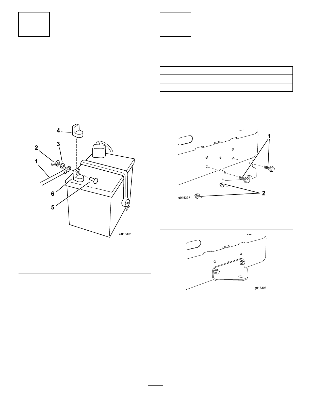
ConnectingtheBattery
NoPartsRequired
Procedure
1.Locatethebatteryandnegativebatterycable.
2.Removetheplasticcapfromthenegativebatterypost.
3.Removethefastenersonthenegativebatterycable,
andusethemtosecurethenegativebatterycableto
thenegativebatterypost(
Figure1).
InstallingtheRearHitch
Partsneededforthisprocedure:
1Rearhitch
2
Bolt(5/16x1inch)
2
Locknut(5/16inch)
Procedure
InstallthebrackettotheframeasshowninFigure2and
Figure3.
Figure2
Beforeassembly
1.Bolts2.Locknuts
Figure1
1.Negativebatterycable4.Negativebatterypostcap
2.Wingnut
3.Washer6.Negativebatterypost
5.Carriagebolt
Figure3
Afterassembly
2
Page 3

3
G014932
1
2
3
4
5
4
SettingUptheMotion-control Levers
NoPartsRequired
Procedure
1.Locatethemotion-controlleversattached,butfolded
downonthemachine.
2.Removetheupperbolt(3/8x1inch)andwasher;
loosenthelowerbolt(3/8x1inch).
3.Raisethemotioncontrolleverstotheuprightposition.
4.Aligntheholesinthemotion-controlleverwiththe
holesinthecontrol-armshaft,andinstallthebolt
andwasherremovedpreviously.Repeatthisforboth
controlslevers.
Note:Handtightenallfasteners.
5.Movethemotion-controlleverstotheparkposition,
raisetheseat,andmovethecontrolleversbacktothe
centerposition(neutral).
ConnectingtheSeatHoldBar
NoPartsRequired
Procedure
1.Locatetheseat-holdbarontheframeofthemachine.
2.Removethefasteners.
3.Installtheseatholdbartotheseatframe.
4.Securethebarwiththewasherandcotterpinremoved
previously(
Figure4).
6.Verifythatthemotion-controlleversareproperly
aligned.
Note:Adjustasnecessary.Tightenallfasteners.
Figure4
1.Cotterpin4.Seatholdbar
2.Washer
3.Seat
5.Holeforpin,seatholdbar
3
Page 4

5
6
CheckingtheMower Adjustment
NoPartsRequired
Procedure
Adjusttheside-to-sidelevelandthefront-to-rearbladeslope.
UsetherelevantproceduresintheOperator'sManualtoverify
thatthedeckislevel,andmakeanyadjustmentsasnecessary.
RefertotheOperator'sManualformoreinformation.
CompletingtheSetup
Partsneededforthisprocedure:
1Ignitionkey
1
Hosecoupling(notincludedwithCEmodels)
1
Operator'sManual
1
EngineOperator'sManual
1
Operatortrainingmaterial
Procedure
CheckingtheTirePressure
Checkthefrontandreartiresforproperination;referto
CheckingtheTirePressureintheOperator'sManualforthe
recommendedinationpressure.
CheckingtheSide-DischargeChute
Removethepackingrestraintholdingthesidedischargechute
upandlowerthechuteintoplace.
CheckingtheEngine-OilLevel
Beforeyoustarttheengineandusethemachine,checkthe
oillevelintheenginecrankcase;refertoCheckingtheOil
LevelintheOperator'sManual.
Keepallthefollowingitemswiththemachine:
•Ignitionkey
•Hosecoupling(notincludedinCEmodels)
•Operator'sManual
•EngineOperator'sManual
•ViewtheOperatortrainingmaterialbeforeoperatingthe
machine.
4
 Loading...