

Page 1
FormNo.3361-182RevA
TimeCutter
®
Z4200andZ5000
RidingMower
ModelNo.74380—SerialNo.290000001andUp
ModelNo.74391—SerialNo.290000001andUp
Registeratwww.T oro.com.OriginalInstructions(EN)
Page 2
Introduction
Readthisinformationcarefullytolearnhowtooperate
andmaintainyourproductproperlyandtoavoidinjury
andproductdamage.Youareresponsibleforoperating
theproductproperlyandsafely.
YoumaycontactTorodirectlyatwww .Toro.comfor
productandaccessoryinformation,helpndinga
dealer,ortoregisteryourproduct.
Wheneveryouneedservice,genuineToroparts,or
additionalinformation,contactanAuthorizedService
DealerorToroCustomerServiceandhavethemodel
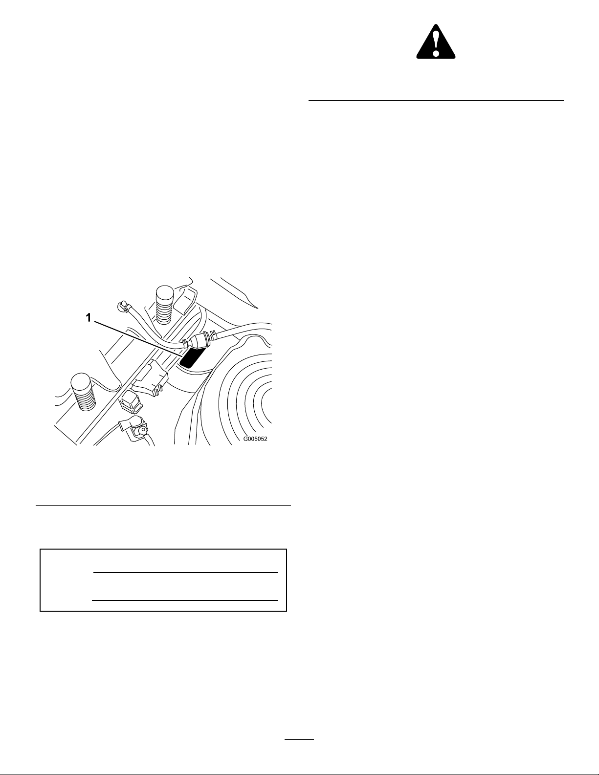
andserialnumbersofyourproductready .Figure1
identiesthelocationofthemodelandserialnumbers
ontheproduct.Writethenumbersinthespace
provided.
Figure1
Undertheseat
1.Modelandserialnumberplate
Writetheproductmodelandserialnumbersinthespace
below:
ModelNo.
SerialNo.
Thismanualidentiespotentialhazardsandhas
safetymessagesidentiedbythesafetyalertsymbol
(Figure2),whichsignalsahazardthatmaycauseserious
injuryordeathifyoudonotfollowtherecommended
precautions.
Figure2
1.Safetyalertsymbol.
Thismanualusestwootherwordstohighlight
information.Importantcallsattentiontospecial
mechanicalinformationandNoteemphasizesgeneral
informationworthyofspecialattention.
Contents
Introduction.................................................................2
Safety...........................................................................3
SafeOperationPracticesforRide-on(riding)
RotaryLawnmowerMachines...........................3
SafeOperatingPractices.......................................3
ToroRidingMowerSafety....................................5
Model74380........................................................5
Model74391........................................................6
SlopeChart..........................................................7
SafetyandInstructionalDecals.............................8
ProductOverview......................................................12
Controls.............................................................13
Operation...................................................................14
ThinkSafetyFirst...............................................14
RecommendedFuel............................................14
CheckingtheEngineOilLevel............................16
StartingtheEngine.............................................16
OperatingtheBlades..........................................17
StoppingtheEngine...........................................18
TheSafetyInterlockSystem................................18
DrivingForwardorBackward.............................19
StoppingtheMachine.........................................20
AdjustingtheHeightofCut................................20
PositioningtheSeat............................................20
AdjustingtheMotionControlLevers..................20
PushingtheMachinebyHand.............................21
GrassDeector..................................................22
ConvertingtoSideDischarge(ForModels
with42InchDecks)........................................22
ConvertingtoSideDischarge(ForModels
with50InchDecks)........................................23
OperatingTips...................................................24
Maintenance...............................................................26
RecommendedMaintenanceSchedule(s)................26
PremaintenanceProcedures....................................27
RaisingtheSeat..................................................27
AccessingtheBattery.........................................27
Lubrication.............................................................27
GreasingtheBearings.........................................27
©2008—TheToro®Company
8111LyndaleAvenueSouth
Bloomington,MN55420
Contactusatwww.Toro.com.
2
PrintedintheUSA.
AllRightsReserved
Page 3

EngineMaintenance...............................................28
ServicingtheAirCleaner....................................28
ServicingtheEngineOil.....................................29
ServicingtheSparkPlug.....................................31
CleaningtheBlowerHousing..............................31
FuelSystemMaintenance.......................................32
ReplacingtheFuelFilter.....................................32
ElectricalSystemMaintenance................................33
ChargingtheBattery...........................................33
ServicingtheFuses.............................................34
DriveSystemMaintenance.....................................35
CheckingtheTirePressure.................................35
MowerMaintenance...............................................36
ServicingtheCuttingBlades...............................36
LevelingtheMowerDeck...................................38
RemovingtheMower.........................................40
MowerBeltMaintenance....................................41
InstallingtheMower...........................................42
ReplacingtheGrassDeector.............................42
Cleaning.................................................................43
WashingtheUndersideoftheMower..................43
Storage.......................................................................44
CleaningandStorage..........................................44
Troubleshooting.........................................................46
Schematics.................................................................48
Safety
SafeOperationPractices
forRide-on(riding)Rotary
LawnmowerMachines
ThismachinemeetsorexceedsEuropeanStandardsin
effectatthetimeofproduction.However,improper
useormaintenancebytheoperatororownercan
resultininjury.Toreducethepotentialforinjury,
complywiththesesafetyinstructionsandalwayspay
attentiontothesafetyalertsymbol,whichmeans
CAUTION,WARNING,orDANGER-“personal
safetyinstruction.”Failuretocomplywiththe
instructionmayresultinpersonalinjuryordeath.
SafeOperatingPractices
ThefollowinginstructionsarefromtheENstandard
EN836:1997.
Thisproductiscapableofamputatinghandsand
feetandthrowingobjects.Alwaysfollowallsafety
instructionstoavoidseriousinjuryordeath.
Training
•Readtheinstructionscarefully.Befamiliarwiththe
controlsandtheproperuseoftheequipment.
•Neverallowchildrenorpeopleunfamiliarwiththese
instructionstousethelawnmower.Localregulations
canrestricttheageoftheoperator.
•Nevermowwhilepeople,especiallychildren,orpets
arenearby .
•Keepinmindthattheoperatororuserisresponsible
foraccidentsorhazardsoccurringtootherpeopleor
theirproperty.
•Donotcarrypassengers.
•Alldriversshouldseekandobtainprofessional
andpracticalinstruction.Suchinstructionshould
emphasize:
–theneedforcareandconcentrationwhen
workingwithride-onmachines;
–controlofaride-onmachineslidingonaslope
willnotberegainedbytheapplicationofthe
brake.Themainreasonsforlossofcontrolare:
◊insufcientwheelgrip;
◊beingdriventoofast;
◊inadequatebraking;
◊thetypeofmachineisunsuitableforitstask;
3
Page 4

◊lackofawarenessoftheeffectofground
conditions,especiallyslopes;
◊incorrecthitchingandloaddistribution.
–stayalertforhumpsandhollowsandother
hiddenhazards;
•Usecarewhenpullingloads.
Preparation
•Whilemowing,alwayswearsubstantialfootwearand
longtrousers.Donotoperatetheequipmentwhen
barefootorwearingopensandals.
•Thoroughlyinspecttheareawheretheequipment
istobeusedandremoveallobjectswhichmaybe
thrownbythemachine.
•Warning-Fuelishighlyammable.
–Storefuelincontainersspecicallydesignedfor
thispurpose.
–Refueloutdoorsonlyanddonotsmokewhile
refuelling.
–Addfuelbeforestartingtheengine.Never
removethecapofthefueltankoraddfuelwhile
theengineisrunningorwhentheengineishot.
–Iffuelisspilled,donotattempttostartthe
enginebutmovethemachineawayfromthe
areaofspillageandavoidcreatinganysourceof
ignitionuntilfuelvaporshavedissipated.
–Replaceallfueltanksandcontainercapssecurely.
•Replacefaultysilencers.
•Beforeusing,alwaysvisuallyinspecttoseethatthe
blades,bladeboltsandcutterassemblyarenotworn
ordamaged.Replacewornordamagedbladesand
boltsinsetstopreservebalance.
•Onmulti-bladedmachines,takecareasrotatingone
bladecancauseotherbladestorotate.
–Useonlyapproveddrawbarhitchpoints.
–Limitloadstothoseyoucansafelycontrol.
–Donotturnsharply.Usecarewhenreversing.
•Watchoutfortrafcwhencrossingornearroadways.
•Stopthebladesrotatingbeforecrossingsurfaces
otherthangrass.
•Whenusinganyattachments,neverdirectdischarge
ofmaterialtowardbystandersnorallowanyonenear
themachinewhileinoperation.
•Neveroperatethemachinewithdamagedguardsor
withoutsafetyprotectivedevicesinplace.
•Donotchangetheenginegovernorsettingsor
overspeedtheengine.Operatingtheengineat
excessivespeedcanincreasethehazardofpersonal
injury.
•Beforeleavingtheoperator’sposition:
–disengagethepowertake-offandlowerthe
attachments;
–changeintoneutralandsettheparkingbrake;
–stoptheengineandremovethekey.
•Disengagedrivetoattachments,stoptheengine,
anddisconnectthesparkplugwire(s)orremovethe
ignitionkey
–beforeclearingblockagesoruncloggingchute;
–beforechecking,cleaningorworkingonthe
lawnmower;
Operation
•Bealert,slowdownandusecautionwhenmaking
turns.Lookbehindandtothesidebeforechanging
directions.
•Donotoperatetheengineinaconnedspacewhere
dangerouscarbonmonoxidefumescancollect.
•Mowonlyindaylightoringoodarticiallight.
•Beforeattemptingtostarttheengine,disengageall
bladeattachmentclutchesandshiftintoneutral.
•Donotuseonslopesofmorethan15degrees.
•Rememberthereisnosuchthingasasafeslope.
Travelongrassslopesrequiresparticularcare.To
guardagainstoverturning:
–donotstoporstartsuddenlywhengoingupor
downhill;
–uselowspeedsonslopesandduringtightturns;
–afterstrikingaforeignobject.Inspectthe
lawnmowerfordamageandmakerepairsbefore
restartingandoperatingtheequipment;
–ifthemachinestartstovibrateabnormally(check
immediately).
•Disengagedrivetoattachmentswhentransporting
ornotinuse.
•Stoptheengineanddisengagedrivetoattachment
–beforerefuelling;
–beforeremovingthegrasscatcher;
–beforemakingheightadjustmentunless
adjustmentcanbemadefromtheoperator’s
position.
•Reducethethrottlesettingduringenginerun-out
and,iftheengineisprovidedwithashut-offvalve,
turnthefueloffattheconclusionofmowing.
4
Page 5

MaintenanceandStorage
•Keepallnuts,boltsandscrewstighttobesurethe
equipmentisinsafeworkingcondition.
•Neverstoretheequipmentwithfuelinthetank
insideabuildingwherefumescanreachanopen
ameorspark.
•Allowtheenginetocoolbeforestoringinany
enclosure.
•Toreducetherehazard,keeptheengine,silencer,
batterycompartmentandfuelstorageareafreeof
grass,leaves,orexcessivegrease.
•Checkthegrasscatcherfrequentlyforwearor
deterioration.
•Replacewornordamagedpartsforsafety.
•Ifthefueltankhastobedrained,thisshouldbe
doneoutdoors.
•Whenmachineistobeparked,storedorleft
unattended,lowerthecuttingmeans.
ToroRidingMowerSafety
Thefollowinglistcontainssafetyinformationspecicto
Toroproductsorothersafetyinformationthatyoumust
knowthatisnotincludedintheCENstandard.
•Donotmowslopeswhengrassiswet.Slippery
conditionsreducetractionandcouldcausesliding
andlossofcontrol.
•Donotmakesuddenturnsorrapidspeedchanges.
•Useawalkbehindmowerand/orahandtrimmer
neardrop-offs,ditches,steepbanks,orwater.
•Reducespeedanduseextremecautiononslopes.
•Removeormarkobstaclessuchasrocks,treelimbs,
etc.frommowingarea.Tallgrasscanhideobstacles.
•Watchforditches,holes,rocksdips,andrisesthat
changetheoperatingangle,asroughterraincould
overturnthemachine.
•Avoidsuddenstartswhenmowinguphillbecause
themowermaytipbackwards.
•Beawarethatlossoftractionmayoccurgoing
downhill.Weighttransfertothefrontwheelsmay
causedrivewheelstoslipandcauselossofbraking
andsteering.
•Alwaysavoidsuddenstartingorstoppingona
slope.Iftireslosetraction,disengagethebladesand
proceedslowlyofftheslope.
•Followthemanufacturer’srecommendationsfor
wheelweightsorcounterweightstoimprovestability.
•Engineexhaustcontainscarbonmonoxide,whichis
anodorless,deadlypoisonthatcankillyou.Donot
runengineindoorsorinanenclosedarea.
•Keephands,feet,hairandlooseclothingawayfrom
attachmentdischargearea,undersideofmowerand
anymovingpartswhileengineisrunning.
•Donottouchequipmentorattachmentpartswhich
maybehotfromoperation.Allowtocoolbefore
attemptingtomaintain,adjust,orservice.
•Batteryacidispoisonousandcancauseburns.Avoid
contactwithskin,eyesandclothing.Protectyour
face,eyes,andclothingwhenworkingwithabattery.
•Batterygasescanexplode.Keepcigarettes,sparks,
andamesawayfrombattery.
•UseonlygenuineTororeplacementpartstoensure
thatoriginalstandardsaremaintained.
•UseonlyToro-approvedattachments.
SlopeOperation
•Donotmowslopesgreaterthan15degrees.
•Donotmowneardrop-offs,ditches,steepbanks,
orwater.Wheelsdroppingoveredgescancause
rollovers,whichmayresultinseriousinjury,death,
ordrowning.
•Useextremecarewithgrasscatchersorother
attachments.Thesecanchangethestabilityofthe
machineandcauselossofcontrol.
Model74380
SoundPressure
ThisunithasanequivalentcontinuousA-weighted
soundpowerlevelattheoperatorearof100dBA,based
onmeasurementsofidenticalmachinesperEN11094.
SoundPower
Thisunithasaguaranteedsoundpowerlevelof105
dBA,basedonmeasurementsofidenticalmachinesper
ISO11094.
Vibration
ThisunithasanequivalentcontinuousA-weighted
hand/armvibrationlevelof4.43m/s
measurementsofidenticalmachinesperEN1033.
ThisunithasanequivalentcontinuousA-weighted
wholebodyvibrationlevelof0.63m/s
measurementsofidenticalmachinesperEN1032.
2
,basedon
2
,basedon
5
Page 6

Model74391
SoundPressure
Thisunithasamaximumsoundpressurelevelatthe
operator’searof92dBA,basedonmeasurementsof
identicalmachinesperEN836andISO11201.
SoundPower
Thisunithasaguaranteedsoundpowerlevelof105
dBA,basedonmeasurementsofidenticalmachinesper
ISO11094.
Vibration
Thisunitdoesnotexceedahand/armvibrationlevel
of4.04m/s2,basedonmeasurementsofidentical
machinesperEN836andEN1033.
Thisunitdoesnotexceedawholebodyvibrationlevel
of0.70m/s2,basedonmeasurementsofidentical
machinesperEN836andEN1032.
6
Page 7
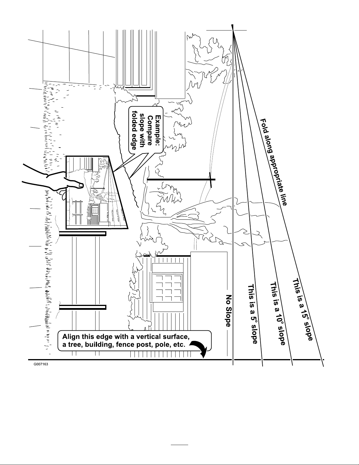
SlopeChart7SafetyandInstructionalDecals
Page 8
Safetydecalsandinstructionsareeasilyvisibletotheoperatorandarelocatednearanyareaof
potentialdanger.Replaceanydecalthatisdamagedorlost.
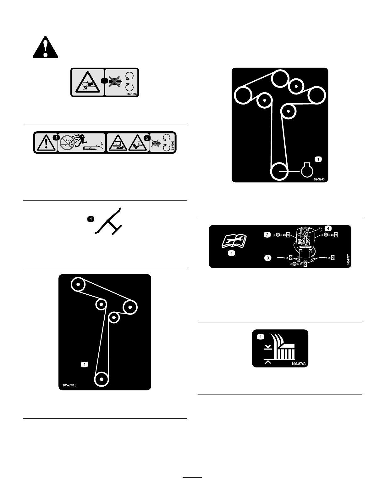
114-1606
1.Entanglementhazard,belt—keepallguardsinplace.
93-7009
1.Warning—don’toperatethemowerwiththedeectorupor
removed;keepthedeectorinplace.
2.Cutting/dismembermenthazardofhandorfoot,mower
blade—stayawayfrommovingparts.
99-3943
ForModelswith50InchDecks
1.Engine
Manufacturer’sMark
1.Indicatesthebladeisidentiedasapartfromtheoriginal
machinemanufacturer.
105-7015
ForModelswith42InchDecks
106-8717
1.Readtheinstructionsbeforeservicingorperforming
maintenance.
2.Checktirepressureevery25operatinghours.
3.Greaseevery25operatinghours.
4.Engine
106-8743
1.Heightofcut
8
Page 9
110-6691
1.Thrownobjecthazard—keepbystandersasafedistance
fromthemachine.
2.Thrownobjecthazard,mower—donotoperatethewithout
deector,dischargecoverorgrasscollectionsystemin
place.
3.Cutting/dismembermentofhandorfoot—stayawayfrom
movingparts.
112-9750
1.Parkingposition4.Neutral
2.Fast5.Reverse
3.Slow
112-9751
1.Parkingposition4.Neutral
2.Fast5.Reverse
3.Slow
110-6824
1.Height-of-cut
115-2500
1.Choke5.Powertake-off(PTO),
2.Fast
3.Continuousvariable
setting
4.Slow
Bladecontrolswitchon
somemodels
6.Bladecontrolswitch—Off
7.Bladecontrolswitch—On
ForModelswith50InchDecks
1.ReadtheOperator’s
Manual.
2.Heightofcut
1.Bypassleverpositionfor
operatingthemachine
112-9840
3.Removetheignitionkey
andreadtheinstructions
beforeservicingor
performingmaintenance.
114-8531
2.Bypassleverpositionfor
pushingthemachine
9
Page 10
114-8532
1.Bypassleverpositionfor
operatingthemachine
2.Bypassleverpositionfor
pushingthemachine
BatterySymbols
Someorallofthesesymbolsareonyourbattery
1.Explosionhazard
2.Nore,opename,or
smoking.
3.Causticliquid/chemical
burnhazard
4.Weareyeprotection9.Flusheyesimmediately
5.ReadtheOperator’s
Manual.
6.Keepbystandersasafe
7.Weareyeprotection;
8.Batteryacidcancause
10.Containslead;donot
distancefromthebattery.
explosivegasescan
causeblindnessandother
injuries
blindnessorsevereburns.
withwaterandgetmedical
helpfast.
discard.
115-2469
1.Warning—readtheOperator’sManual.
2.Warning—readtheinstructionsbeforeservicingorperformingmaintenance;movethemotioncontrolleverstothepark(brake)
position,removetheignitionkeyanddisconnectthesparkplugwire.
3.Cutting/dismembermenthazard,mowerblade;entanglementhazard,belt—donotopenorremovesafetyshieldswhileengineis
running.
4.Tippinghazard—donotmowslopesgreaterthan15degrees,avoidsuddenandsharpturnswhileonslopes.
5.Lossoftraction/controlhazard,slopes—lossoftraction/controlonaslope,disengagethebladecontrolswitch(PTO),proceed
offtheslopeslowly.
6.Crushing/dismembermenthazardofbystanders,reversing;crushing/dismembermenthazardofbystanders—donotcarry
passengers,lookbehindanddownwhenreversing.
7.Thrownobjecthazard—keepbystandersasafedistancefromthemachine,pickupdebrisbeforeoperating,keepdeectorinplace.
10
Page 11

1.Fuelgauge2.Full
1.Fuelgauge2.Full
115-2450
3.Half
4.Empty
115-2451
3.Half
4.Empty
11
Page 12
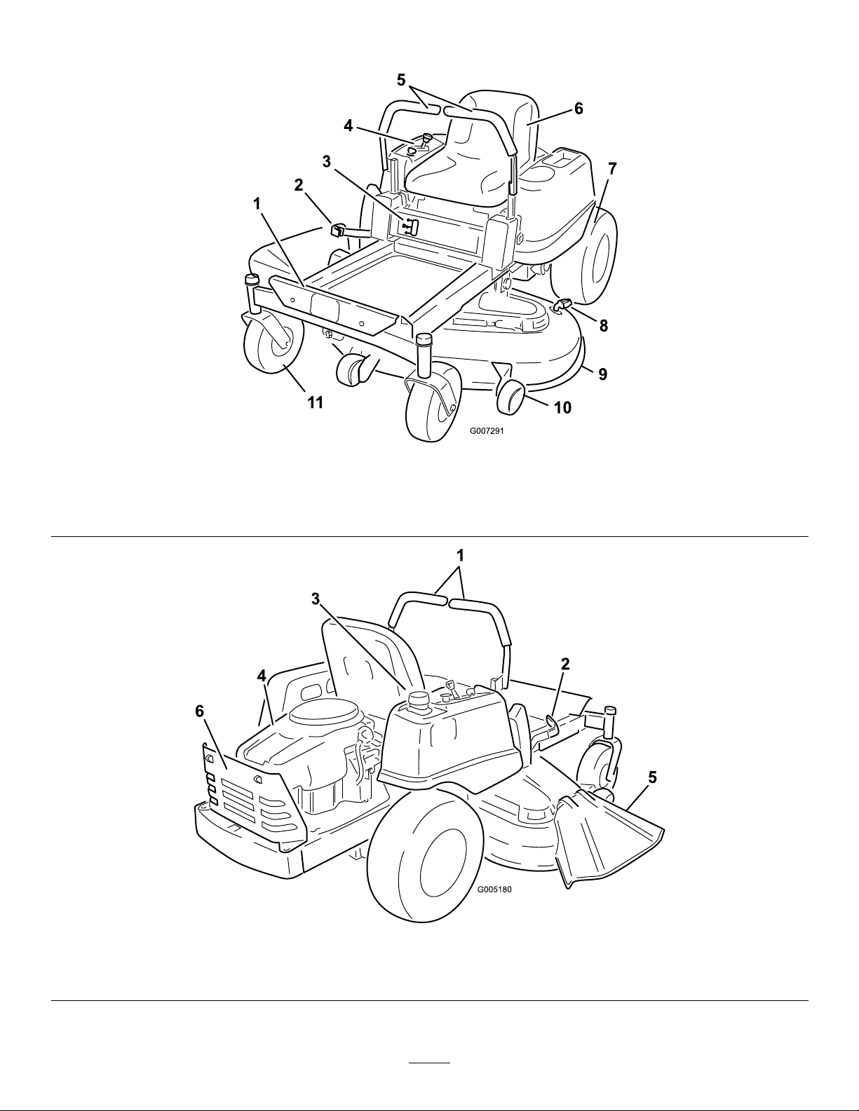
ProductOverview
G005180
1
2
3
4
5
6
1.Footrest
2.Heightofcutlever
3.Fuelgauge
4.Controlpanel
5.Motioncontrollevers
6.Operatorseat
Figure3
7.Reardrivewheel10.Anti-scalproller
8.Washouttting
9.Mowerdeck
11.Frontcasterwheel
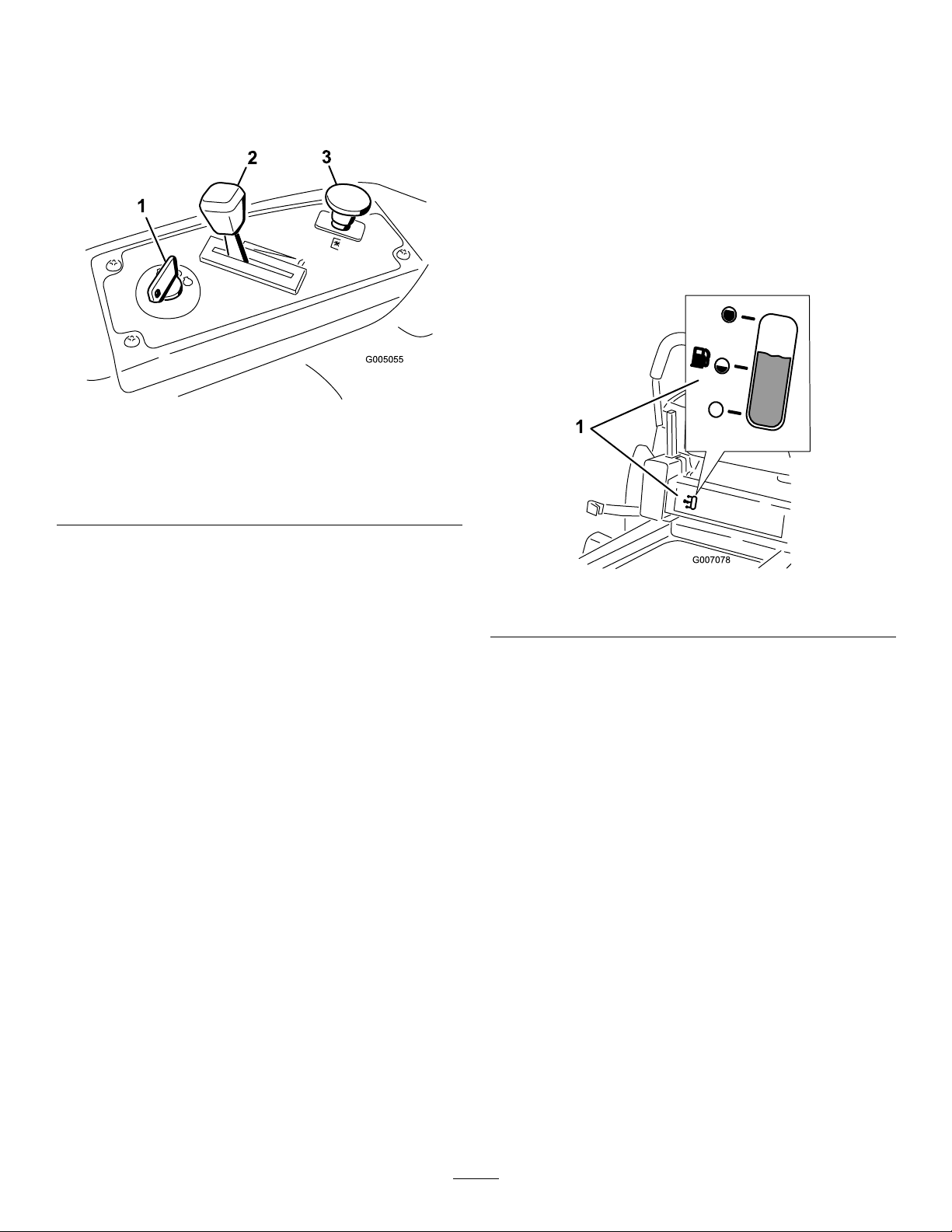
Figure4
1.Motioncontrollevers
2.Heightofcutlever
3.Gastankcap5.Deector
4.Engine6.Engineguard
12
Page 13
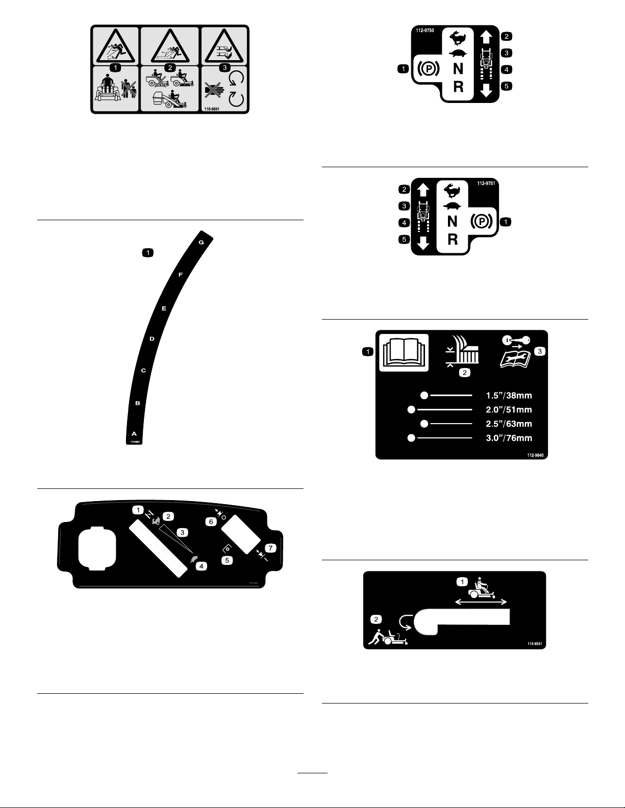
Controls
G005055
1
2
3
BecomefamiliarwithallofthecontrolsinFigure3,
Figure4,andFigure5beforeyoustarttheengineand
operatethemachine.
Figure5
ControlPanel
reverse;wheelspeedisproportionaltotheamountthe
leverismoved.Movethecontrolleversoutwardfrom
thecentertotheparkpositionandexitthemachine
(Figure15).Alwayspositionthemotioncontrollevers
intotheparkpositionwhenyoustopthemachineor
leaveitunattended.
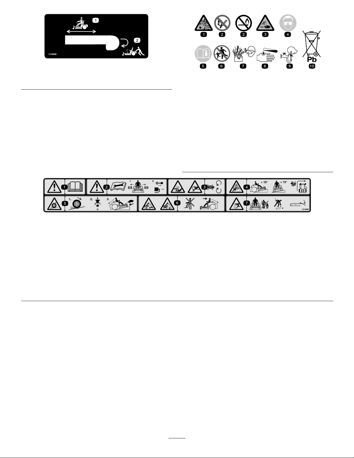
FuelGauge
Thefuelwindowlocatedbelowtheoperatorposition
canbeusedtoverifythelevelofgasolineinthetank
(Figure6).
1.Ignitionswitch3.Bladecontrolswitch
(powertake-off)
2.Throttle/Choke
IgnitionSwitch
Theignitionswitchhasthreepositions,Off,Runand
Start.ThekeywillturntoStartandmovebackto
Runuponrelease.TurningthekeytotheOffposition
willstoptheengine;however,alwaysremovethekey
whenleavingthemachinetopreventsomeonefrom
accidentallystartingtheengine(Figure5).
Throttle/ChokeControl
Thethrottleandchokeiscombinedintoonecontrol
lever.Thethrottlecontrolstheenginespeedandithasa
continuousvariablesettingfromSlowtoFast.Engage
thechokebymovingtheleverpasttheFastsettinguntil
itstops(Figure5).
BladeControlSwitch(PowerTake-Off)
Figure6
1.Fuelgaugewindow
Height-of-CutLever
Theheightofcutleverallowstheoperatortolower
andraisethedeckfromtheseatedposition.Whenthe
leverismovedup,towardtheoperatorthedeckisraised
fromthegroundandwhenmoveddown,awayfromthe
operatoritisloweredtowardtheground.Onlyadjustthe
heightofcutwhilemachineisnotmoving(Figure18).
Thebladecontrolswitch,representedbyapower
take-off(PTO)symbol,engagesanddisengagespower
tothemowerblades(Figure5).
MotionControlLeversandPark
Position
Themotioncontrolleversarespeedsensitivecontrolsof
independentwheelmotors.Movingaleverforwardor
backwardturnsthewheelonthesamesideforwardorin
13
Page 14
Operation
Note:Determinetheleftandrightsidesofthe
machinefromthenormaloperatingposition.
ThinkSafetyFirst
Pleasecarefullyreadallofthesafetyinstructionsand
decalsinthesafetysection.Knowingthisinformation
couldhelpyou,yourfamily,petsorbystandersavoid
injury.
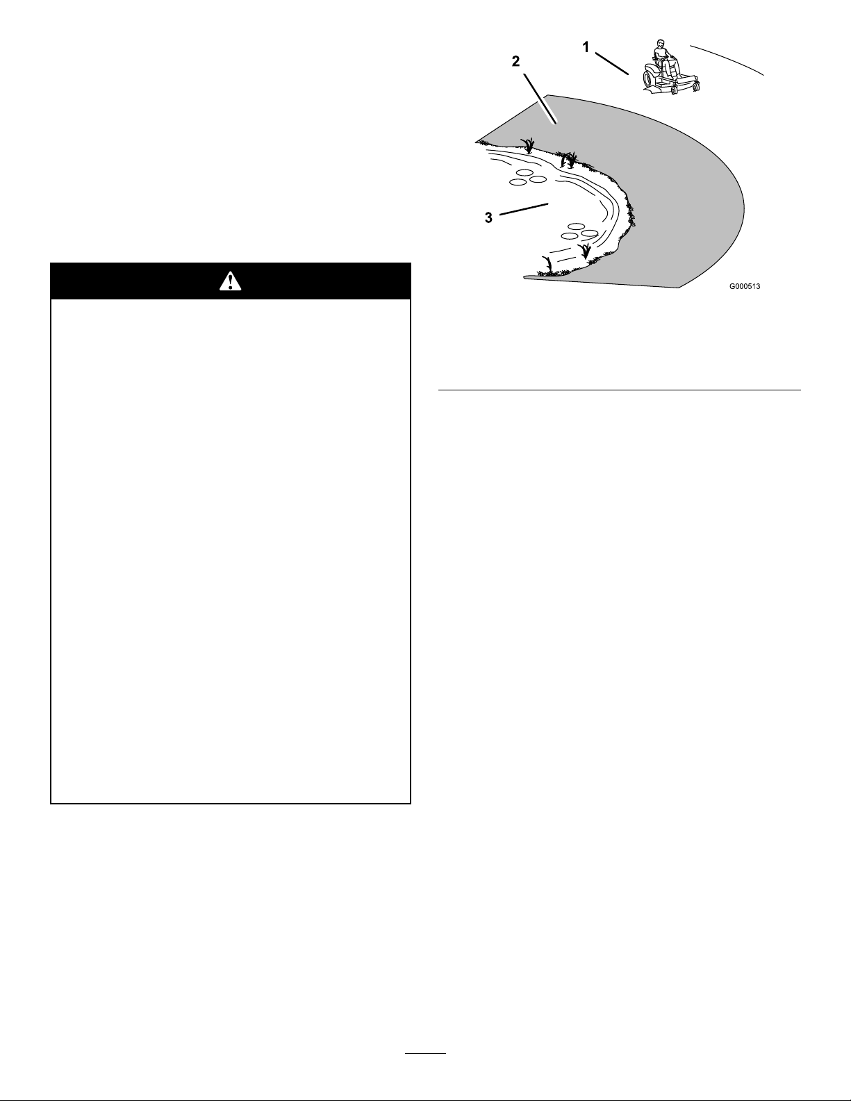
Mowingonwetgrassorsteepslopescancause
slidingandlossofcontrol.
Wheelsdroppingoveredgescancauserollovers,
whichmayresultinseriousinjury,deathor
drowning.
Alossoftractionisalossofsteeringcontrol.
Toavoidlossofcontrolandpossibilityof
rollover:
•Donotmowneardrop-offsornearwater.
•Donotmowslopesgreaterthan15degrees.
•Reducespeedanduseextremecautionon
slopes.
•Whenmowingslopes,graduallyworkfrom
lowertohigherareasontheincline.
•Avoidsuddenturnsorrapidspeedchanges.
•Turnup,intoaninclinewhenchanging
directionsonslopes.Turningdownthe
slopereducestraction.
Figure7
1.SafeZone-usetheTimeCutterhere
2.Usewalkbehindmowerand/orhandtrimmerneardrop-offs
andwater.
3.Water
RecommendedFuel
UseUNLEADEDRegularGasolinesuitablefor
automotiveuse(87pumpoctaneminimum).Leaded
regulargasolinemaybeusedifunleadedregularisnot
available.
Important:Neverusemethanol,gasoline
containingmethanol,orgasoholcontainingmore
than10percentethanolbecausethefuelsystem
couldbedamaged.Donotmixoilwithgasoline.
•Attachmentschangethehandling
characteristicsofthemachine.Useextra
cautionwhenusingattachmentswiththe
machine.
14
Page 15

Incertainconditions,gasolineisextremely
ammableandhighlyexplosive.Areor
explosionfromgasolinecanburnyouand
othersandcandamageproperty.
•Fillthefueltankoutdoors,inanopenarea,
whentheengineiscold.Wipeupany
gasolinethatspills.
Incertainconditionsduringfueling,static
electricitycanbereleasedcausingaspark
whichcanignitethegasolinevapors.Are
orexplosionfromgasolinecanburnyouand
othersandcandamageproperty.
•Alwaysplacegasolinecontainersonthe
groundawayfromyourvehiclebeforelling.
•Neverllthefueltankinsideanenclosed
trailer.
•Donotllthefueltankcompletelyfull.Add
gasolinetothefueltankuntilthebodyof
thetankisfullbutfueldoesnotlltheneck
ofthetank.Thisemptyspaceinthetank
allowsgasolinetoexpand.
•Neversmokewhenhandlinggasoline,and
stayawayfromanopenameorwhere
gasolinefumesmaybeignitedbyaspark.
•Storegasolineinanapprovedcontainerand
keepitoutofthereachofchildren.Never
buymorethana30-daysupplyofgasoline.
•Donotoperatewithoutentireexhaust
systeminplaceandinproperworking
condition.
•Donotllgasolinecontainersinsidea
vehicleoronatruckortrailerbedbecause
interiorcarpetsorplastictruckbedliners
mayinsulatethecontainerandslowtheloss
ofanystaticcharge.
•Whenpractical,removegas-powered
equipmentfromthetruckortrailerand
refueltheequipmentwithitswheelsonthe
ground.
•Ifthisisnotpossible,thenrefuelsuch
equipmentonatruckortrailerfroma
portablecontainer,ratherthanfroma
gasolinedispensernozzle.
•Ifagasolinedispensernozzlemustbeused,
keepthenozzleincontactwiththerimof
thefueltankorcontaineropeningatall
timesuntilfuelingiscomplete.
Gasolineisharmfulorfatalifswallowed.
Long-termexposuretovaporscancauseserious
injuryandillness.
•Avoidprolongedbreathingofvapors.
•Keepfaceawayfromnozzleandgastankor
conditioneropening.
•Keepgasawayfromeyesandskin.
UsingStabilizer/Conditioner
Useafuelstabilizer/conditionerinthemachineto
providethefollowingbenets:
•Keepsgasolinefreshduringstorageof30daysor
less.Forlongerstorageitisrecommendedthatthe
fueltankbedrained.
•Cleanstheenginewhileitruns.
•Eliminatesgum-likevarnishbuildupinthefuel
system,whichcauseshardstarting.
15
Page 16
Addthecorrectamountofgasstabilizer/conditioner
G005302
1
2
3
4
1
2
G005056
1
2
tothegas.
allowsgasolinetoexpand.Donotllthefueltank
completelyfull.
Note:Afuelstabilizer/conditionerismosteffective
whenmixedwithfreshgasoline.Tominimizethe
chanceofvarnishdepositsinthefuelsystem,usefuel
stabilizeratalltimes.
Gasoline/Alcoholblends
Gasohol(upto10percentethylalcohol,90percent
unleadedgasolinebyvolume)isapprovedforfueluse
bytheenginemanufacturer.Othergasoline/alcohol
blends,suchasE85,arenotapproved.
Gasoline/Etherblends
MethylTertiaryButylEther(MTBE)andunleaded
gasolineblends(uptoamaximumof15percentMTBE
byvolume)areapprovedforfuelusebytheengine
manufacturer.Othergasoline/etherblendsarenot
approved.
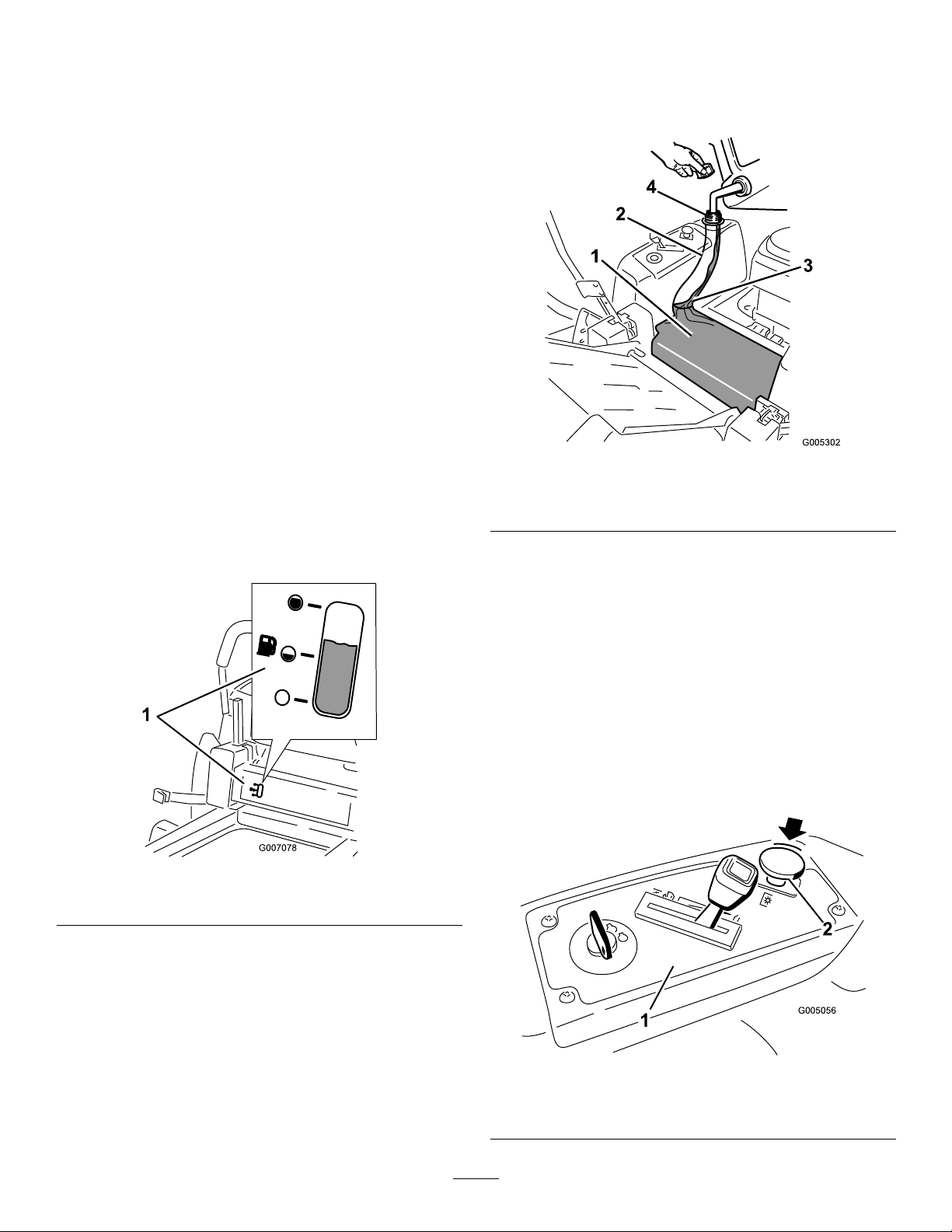
FuelGauge
Usethefuelwindowbelowtheoperatortoverifythe
levelofgasolinebeforellingthetank(Figure8).
4.Installthefueltankcapsecurely.Wipeupany
gasolinethatmayhavespilled.
Figure9
1.Gastankbody
2.Gastankneck4.Gastankopening
3.Filltohere,approximately
CheckingtheEngineOilLevel
Figure8
1.Fuelgaugewindow
FillingtheFuelTank
1.Shuttheengineoffandsetthemotioncontrolsto
theparkposition.Raisetheseatsothegastankis
visiblewhilefueling.
2.Cleanaroundthefueltankcapandremovethecap.
3.Addunleadedregulargasolineuntilthebodyofthe
tankisfullbutfueldoesnotlltheneckofthe
tank(Figure9).Thisspaceintheneckofthetank
Beforeyoustarttheengineandusethemachine,check
theoillevelintheenginecrankcase;refertoChecking
theOilLevelintheEngineMaintenancesection.
StartingtheEngine
1.Sitdownontheseatandmovethemotioncontrols
outwardtotheparkposition.
2.Disengagethebladesbymovingthebladecontrol
switchtoOff(Figure10).
Figure10
1.Controlpanel2.Bladecontrolswitch—Off
position
16
Page 17

3.MovethethrottlelevertoChokebeforestartinga
1
2
2
3
4
5
6
G005057
1
2
2
3
4
5
6
1
2
3
4
5
6
G005058
1
2
3
4
5
6
coldengine(Figure11).
Note:Awarmorhotenginemaynotrequire
choking.
Figure12
1.Controlpanel4.Off
2.Ignitionkey—runposition5.Run
3.Ignitionkey—startposition
6.Start
5.Aftertheenginestarts,movethethrottleleverto
Fast(Figure11).Iftheenginestallsorhesitates,
movethethrottleleverbacktoChokeforafew
seconds.Repeatthisasrequired.
Figure11
1.Controlpanel
2.Throttle/choke
lever—chokeposition
3.Choke6.Slow
4.Fast
5.Continuousvariable
setting
4.TurntheignitionkeytoStarttoenergizethestarter.
Whentheenginestarts,releasethekey(Figure12).
Important:Donotengagethestarterformore
than10secondsatatime.Iftheenginefails
tostart,allowa60secondcool-downperiod
betweenattempts.Failuretofollowthese
instructionscandamagethestartermotor.
OperatingtheBlades
Thebladecontrolswitch,representedbyapower
take-off(PTO)symbol,engagesanddisengagespower
tothemowerblades.Thisswitchcontrolspowertoany
attachmentsthatdrawpowerfromtheengine,including
themowerdeckandcuttingblades.
EngagingtheBlades
Important:Donotengagethebladeswhen
parkedintallgrass.Beltorclutchdamagecan
occur.
1.Releasepressureonthemotioncontrolleversand
placethemachineinneutral.
2.MovethethrottletotheFastposition.
Note:Alwaysengagethebladeswiththethrottle
intheFastposition.
3.Pulluponthebladecontrolswitchtomoveitto
theOnpositionandengagetheblades(Figure13).
17
Page 18

G005059
121
2
Figure13
1
2
G005056
1
2
1.Controlpanel2.Bladecontrolswitch—On
position
TheSafetyInterlockSystem
Ifsafetyinterlockswitchesaredisconnected
ordamagedthemachinecouldoperate
unexpectedlycausingpersonalinjury.
•Donottamperwiththeinterlockswitches.
•Checktheoperationoftheinterlock
switchesdailyandreplaceanydamaged
switchesbeforeoperatingthemachine.
UnderstandingtheSafetyInterlock
System
DisengagingtheBlades
Pushdownonthebladecontrolswitchtomoveitto
theOffpositionanddisengagetheblades(Figure14).
Figure14
1.Controlpanel2.Bladecontrolswitch—Off
StoppingtheEngine
1.Disengagethebladesbymovingthebladecontrol
switchtoOff(Figure14).
2.MovethethrottlelevertobetweenFastandhalf
throttle(Figure12).
3.TurntheignitionkeytoOff(Figure11)andremove
thekey .
Thesafetyinterlocksystemisdesignedtopreventthe
enginefromstartingunless:
•Thebladesaredisengaged.
•Themotioncontrolleversareintheparkposition.
Thesafetyinterlocksystemalsoisdesignedtostop
theenginewhenthecontrolleversareoutofthepark
positionandyourisefromtheseatwhentheblades
areengaged.
TestingtheSafetyInterlockSystem
Testthesafetyinterlocksystembeforeyouusethe
machineeachtime.Ifthesafetysystemdoesnot
operateasdescribedbelow ,haveanAuthorizedService
Dealerrepairthesafetysystemimmediately .
1.Whilesittingontheseat,withthecontrolleversin
parkposition,andmovethebladecontrolswitch
toOn.Trystartingtheengine;theengineshould
notcrank.
2.Whilesittingontheseat,movethebladecontrol
switchtoOff.Moveeithermotioncontrollever
tothecenter,unlockedposition.Trystartingthe
engine;theengineshouldnotcrank.Repeatwith
theothermotioncontrollever.
3.Whilesittingontheseat,movethebladecontrol
switchtoOff,andlockthemotioncontrolleversin
theparkposition.Starttheengine.Whiletheengine
isrunning,engagethebladecontrolswitch,andrise
slightlyfromtheseat;theengineshouldstop.
4.Whilesittingontheseat,movethebladecontrol
switchtoOff,andlockthemotioncontrollevers
intheparkposition.Starttheengine.Whilethe
engineisrunning,movethemotioncontrollevers
tothecenter,unlockedposition,engagetheblade
controlswitch,andriseslightlyfromtheseat;the
engineshouldstop.
18
Page 19

DrivingForwardorBackward
G008952
G008953
Thethrottlecontrolregulatestheenginespeedas
measuredinrpm(revolutionsperminute).Place
thethrottlecontrolintheFastpositionforbest
performance.Alwaysoperateinthefullthrottle
position.
Themachinecanspinveryrapidly .The
operatormaylosecontrolofthemachine
andcausepersonalinjuryordamagetothe
machine.
•Usecautionwhenmakingturns.
•Slowthemachinedownbeforemaking
sharpturns.
Figure16
Togostraight,applyequalpressuretobothmotion
controllevers(Figure15).
Toturn,releasepressureonthemotioncontrollever
towardthedirectionyouwanttoturn(Figure15).
Thefartheryoumovethemotioncontrolleversin
eitherdirection,thefasterthemachinewillmovein
thatdirection.
Tostop,pullthemotioncontrolleverstoneutral.
Backward
1.Movetheleverstothecenter,unlockedposition.
2.Togobackward,slowlypullthemotioncontrol
leversrearward(Figure17).
Figure15
1.Park(brake)position
2.Centerunlockposition
3.Forward
4.Backward
Forward
1.Movetheleverstothecenter,unlockedposition.
2.Togoforward,slowlypushthemotioncontrol
leversforward(Figure15).
Figure17
Togostraight,applyequalpressuretobothmotion
controllevers(Figure17).
19
Page 20

Toturn,releasethepressureonthemotioncontrol
G009619
1
2
3
4
5
6
7
8
levertowardthedirectionyouwanttoturn.
Tostop,pushthemotioncontrolleverstoneutral.
PositioningtheSeat
Theseatcanmoveforwardandbackward.Positionthe
seatwhereyouhavethebestcontrolofthemachine
andaremostcomfortable.
StoppingtheMachine
Tostopthemachine,movethemotioncontrolleversto
neutralandoutwardtotheparkposition,disengagethe
bladecontrolswitch,ensurethethrottleisinthefast
position,andturntheignitionkeytooff.Rememberto
removethekeyfromtheignitionswitch.
Childrenorbystandersmaybeinjuredifthey
moveorattempttooperatethemowerwhileit
isunattended.
Alwaysremovetheignitionkeyandmovethe
motioncontrolleversoutwardtothepark
positionwhenleavingthemachineunattended,
evenifjustforafewminutes.
AdjustingtheHeightofCut
1.Raisetheheight-of-cutlevertothetransport
position,cuttingheightpositionG(alsothe
4-1/2inch[115mm])(Figure18).
1.Raisetheseatandloosentheadjustmentknobjust
enoughthatseatcanmove(Figure19).
Figure19
1.Adjustmentknob
2.Movetheseattothedesiredpositionandtighten
theknob.
AdjustingtheMotionControl
Levers
AdjustingtheHeight
Themotioncontrolleverscanbeadjustedhigheror
lowerformaximumoperatorcomfort.
1.Removethe2boltsholdingthecontrollevertothe
controlarmshaft(Figure20).
2.Movethecontrollevertothenextsetofholes.
Securetheleverwiththe2bolts(Figure20).
Figure18
1.Height-of-cutlever5.3inch(76mm)
2.4.5inch(1 15mm),
Transportposition
3.4inch(102mm)7.2inch(51mm)
4.3.5inch(89mm)8.1.5inch(38mm)
2.Toadjusttheheightofcut,pullinwardandupon
theleverandmoveittothedesiredposition.
6.2.5inch(64mm)
20
Page 21

G005062
1
2
3
4
Figure20
1.Controlarmshaft3.Slotted,upperhole
2.Controllever
4.Bolt
3.Repeattheadjustmentfortheoppositecontrol
lever.
AdjustingtheTilt
Themotioncontrolleverscanbetiltedforeoraftfor
maximumoperatorcomfort.
1.Loosentheupperboltholdingthecontrolleverto
thecontrolarmshaft.
4.Movethebypassleversrearwardandthendown
tolocktheminplaceasshowninFigure21to
disengagethewheelmotors.Repeatthisoneach
sideofthemachine.
5.Movethemotioncontrolleversinwardtothe
neutralposition.
Themachineisnowabletobepushedbyhand.
Figure21
Rightsideshown
1.Bypassleverlocation
2.Leverpositionforpushing
themachine
3.Leverpositionfor
operatingthemachine
2.Loosenthelowerboltjustenoughtopivotthe
controlleverforeoraft(Figure20).Tightenboth
boltstosecurethecontrolinthenewposition.
3.Repeattheadjustmentfortheoppositecontrol
lever.
PushingtheMachinebyHand
Important:Alwayspushthemachinebyhand.
Nevertowthemachinebecausedamagemay
occur.
ToPushtheMachine
1.Parkthemachineonalevelsurfaceanddisengage
thebladecontrolswitch.
2.Movethemotioncontrolleversoutwardtopark
position,stoptheengine,removethekey,andwait
forallmovingpartstostopbeforeleavingthe
operatingposition.
3.Locatethebypassleversattherearofthemachine,
ontheleftandrightsideoftheframe.
ToOperatetheMachine
Movethebypassleversupwardandpushthemforward,
tothemiddleofthehorizontalslot(Figure21)to
engagethewheelmotors.
21
Page 22

GrassDeector
G009660
1
2
3
4
5
Themowerhasahingedgrassdeectorthatdisperses
clippingstothesideanddowntowardtheturf.
Withoutthegrassdeector,dischargecover,
orcompletegrasscatcherassemblymounted
inplace,youandothersareexposedtoblade
contactandthrowndebris.Contactwith
rotatingmowerblade(s)andthrowndebriswill
causeinjuryordeath.
•Neverremovethegrassdeectorfrom
themowerbecausethegrassdeector
routesmaterialdowntowardtheturf.Ifthe
grassdeectoriseverdamaged,replaceit
immediately.
•Neverputyourhandsorfeetunderthe
mower.
•Nevertrytocleardischargeareaormower
bladesunlessyoumovethebladecontrol
switchtoOffandrotatetheignitionkeyto
Off.Alsoremovethekeyandpullthewire
offthesparkplug(s).
forallmovingpartstostopbeforeleavingthe
operatingposition.
3.Removethe2boltsandnutsthatsecurethe
dischargecovertothemower(Figure22).
Figure22
1.Capnut(1/4inch)
2.Dischargecover5.Removethecover
3.Bolt(1/4x2-1/2inches)
4.Rotatethecoverup
ConvertingtoSideDischarge
(ForModelswith42Inch
Decks)
Themowerdeckandmowerbladesshippedwith
thismachineweredesignedforoptimummulching
performance.Sidedischargeperformancecanbe
improvedbyreplacingthemulchingbladeswith
standardcuttingbladesobtainedfromyourlocal
authorizedT orodealer.T omaintainoptimummulching
performance,alwaysinstallthemulchingbladesthatare
shippedwiththisunitwhenchangingbacktomulching
operation.
RemovingtheDischargeCoverfor
SideDischarge
Note:Ifthebaggerattachmentisaddedtothe
machine,standardbladesmustbeinstalledforproper
baggingfunction.ContactyourlocalauthorizedToro
dealerfortheproperpartnumber.
1.Parkthemachineonalevelsurfaceanddisengage
thebladecontrolswitch.
2.Movethemotioncontrolleversoutwardtopark
position,stoptheengine,removethekey,andwait
4.Removethedischargecoverandlowerthegrass
deectoroverthedischargeopening.
Important:Ensurethemowerhasahinged
grassdeectorthatdispersesclippingstothe
sideanddowntowardtheturf,whileinside
dischargemode.
InstallingtheDischargeCoverfor
Mulching
1.Parkthemachineonalevelsurfaceanddisengage
thebladecontrolswitch.
2.Movethemotioncontrolleversoutwardtopark
position,stoptheengine,removethekey,andwait
forallmovingpartstostopbeforeleavingthe
operatingposition.
3.Liftthegrassdeectorandslidethetabsontop
ofthedischargecoverunderthegrassdeector
retainingrod.Rotatethedischargecoverdownover
theopening,andontothelowerlipofthemower
(Figure23).
22
Page 23

G005652
Figure23
G006475
1
2
3
4
1
1.Dischargecover
2.Capnut(1/4inch)
3.Bolt(1/4x2-1/2inches)
4.Securethedischargecovertothelowerlipofthe
mowerwithtwobolts(1/4x2-1/2inches)andtwo
capnuts(1/4inch)asshowninFigure23.
Note:Donotovertightenthenuts;thiscould
distortthecoverandcausebladecontact.
2.Movethemotioncontrolleversoutwardtopark
position,stoptheengine,removethekey,andwait
forallmovingpartstostopbeforeleavingthe
operatingposition.
3.Removetherightmowerblade.RefertotheMower
Maintenancesection.
4.Removethe2knobsandcurvedwashersthatsecure
therightbafetothemowerasshowninFigure24.
Figure24
1.Knob
2.Curvedwasher
3.Bafestudcomingthrough
themower
5.Removetherightbafeandlowerthegrass
deectoroverthedischargeopeningasshownin
Figure25andFigure24.
ConvertingtoSideDischarge
(ForModelswith50Inch
Decks)
Themowerdeckandmowerbladesshippedwith
thismachineweredesignedforoptimummulching
performance.Sidedischargeperformancecanbe
improvedbyreplacingthemulchingbladeswith
standardcuttingbladesobtainedfromyourlocal
authorizedT orodealer.T omaintainoptimummulching
performance,alwaysinstallthemulchingbladesthatare
shippedwiththisunitwhenchangingbacktomulching
operation.
RemovingtheRightBafeforSide
Discharge
Note:Ifthebaggerattachmentisaddedtothe
machine,standardbladesmustbeinstalledforproper
baggingfunction.ContactyourlocalauthorizedToro
dealerfortheproperpartnumber.
1.Parkthemachineonalevelsurfaceanddisengage
thebladecontrolswitch.
Figure25
1.Rightbafe
2.Curvedwasherandknob4.Tab(mustremainoutside
3.Dischargeopening
ofthemower)
23
Page 24

6.Installthefastenersintotheholesinthetopofthe
mowertopreventyingdebris.
Openholesinthemowerexposeyouandothers
tothrowndebriswhichcancausesevereinjury.
•Neveroperatethemowerwithouthardware
mountedinallholesinthemowerhousing.
•Installthehardwareinthemountingholes
whenyouremovethemulchingbafe.
byuncutgrass.Alwaystrytohaveonesideofthe
mowerfreefromuncutgrass,whichallowsairtobe
drawnintothemower.
CuttingaLawnfortheFirstTime
Cutgrassslightlylongerthannormaltoensurethatthe
cuttingheightofthemowerdoesnotscalpanyuneven
ground.However,thecuttingheightusedinthepastis
generallythebestonetouse.Whencuttinggrasslonger
thansixinchestall,youmaywanttocutthelawntwice
toensureanacceptablequalityofcut.
7.Installtherightmowerblade.RefertotheMower
Maintenancesection.
8.Lowerthegrassdeectoroverthedischarge
opening.
Important:Ensurethemowerhasahinged
grassdeectorthatdispersesclippingstothe
sideanddowntowardtheturf,whileinside
dischargemode.
InstallingtheRightBafeforMulching
1.Parkthemachineonalevelsurfaceanddisengage
thebladecontrolswitch.
2.Movethemotioncontrolleversoutwardtopark
position,stoptheengine,removethekey,andwait
forallmovingpartstostopbeforeleavingthe
operatingposition.
3.Removetherightmowerblade.RefertotheMower
Maintenancesection.
4.Slidetherightbafethroughthedischargeopening
andsecureitusing2knobsandcurvedwashers
(cuppedsidefacingthemower)asshownin
Figure24andFigure25.
Cut1/3oftheGrassBlade
Itisbesttocutonlyabout1/3ofthegrassblade.
Cuttingmorethanthatisnotrecommendedunless
grassissparse,oritislatefallwhengrassgrowsmore
slowly.
MowingDirection
Alternatemowingdirectiontokeepthegrassstanding
straight.Thisalsohelpsdisperseclippingswhich
enhancesdecompositionandfertilization.
MowatCorrectIntervals
Normally,moweveryfourdays.Butremember,
grassgrowsatdifferentratesatdifferenttimes.So
tomaintainthesamecuttingheight,whichisagood
practice,mowmoreofteninearlyspring.Asthegrass
growthrateslowsinmidsummer,mowlessfrequently.
Ifyoucannotmowforanextendedperiod,rstmow
atahighcuttingheight;thenmowagaintwodayslater
atalowerheightsetting.
CuttingSpeed
Important:Ensurethatthetabonthefarright
sideoftherightbafeisoutsideofthemower
andisushwiththemowerwall.
5.Installtherightmowerblade.RefertotheMower
Maintenancesection.
OperatingTips
FastThrottleSetting
Forbestmowingandmaximumaircirculation,operate
theengineattheFastposition.Airisrequiredto
thoroughlycutgrassclippings,sodonotsetthe
height-of-cutsolowastototallysurroundthemower
Toimprovecutquality,useaslowergroundspeed.
AvoidCuttingTooLow
Ifthecuttingwidthofthemoweriswiderthanthe
moweryoupreviouslyused,raisethecuttingheightto
ensurethatuneventurfisnotcuttooshort.
LongGrass
Ifthegrassiseverallowedtogrowslightlylongerthan
normal,orifitcontainsahighdegreeofmoisture,raise
thecuttingheighthigherthanusualandcutthegrassat
thissetting.Thencutthegrassagainusingthelower,
normalsetting.
24
Page 25

WhenStopping
Ifthemachine’sforwardmotionmustbestoppedwhile
mowing,aclumpofgrassclippingsmaydropontoyour
lawn.T oavoidthis,moveontoapreviouslycutarea
withthebladesengaged.
KeeptheUndersideoftheMower
Clean
Cleanclippingsanddirtfromtheundersideofthe
moweraftereachuse.Ifgrassanddirtbuildupinside
themower,cuttingqualitywilleventuallybecome
unsatisfactory.
BladeMaintenance
Maintainasharpbladethroughoutthecuttingseason
becauseasharpbladecutscleanlywithouttearingor
shreddingthegrassblades.Tearingandshreddingturns
grassbrownattheedges,whichslowsgrowthand
increasesthechanceofdisease.Checkthecutterblades
dailyforsharpness,andforanywearordamage.File
downanynicksandsharpenthebladesasnecessary.If
abladeisdamagedorworn,replaceitimmediatelywith
agenuineTororeplacementblade.
25
Page 26

Maintenance
Note:Determinetheleftandrightsidesofthemachinefromthenormaloperatingposition.
RecommendedMaintenanceSchedule(s)
MaintenanceService
Interval
Beforeeachuseordaily
Every25hours
Every100hours
Every200hours
Every500hours
Beforestorage
MaintenanceProcedure
•Checkthesafetyinterlocksystem.
•Checktheaircleanerfordirty,looseordamagedparts.
•Checktheengineoillevel.
•Checkairintakeandcoolingareas,cleanasnecessary.
•Checkthecuttingblades.
•Inspectthegrassdeectorfordamage
•Cleanthemowerhousing.
•Greasealllubricationpoints.
•Servicethepaperelement.(moreoftenunderextremelydusty ,dirtyconditions)
•Checktirepressure.
•Checkthebeltsforwear/cracks.
•Replacethepaperelement.(moreoftenunderextremelydusty ,dirtyconditions)
•Changetheengineoilandlter.
•Cleantheblowerhousing(moreoftenunderextremelydusty,dirtyconditions).
•Replacethefuellter.
•Checksparkplugconditionandgap.
•Replacethesparkplug.
•Chargethebatteryanddisconnectbatterycables.
•Performallmaintenanceprocedureslistedabovebeforestorage.
•Paintanychippedsurfaces.
Important:Refertoyourengineoperator’smanualforadditionalmaintenanceprocedures.
Ifyouleavethekeyintheignitionswitch,someonecouldaccidentlystarttheengineandseriously
injureyouorotherbystanders.
Removethekeyfromtheignitionanddisconnectthewirefromthesparkplugbeforeyoudoany
maintenance.Setthewireasidesothatitdoesnotaccidentallycontactthesparkplug.
26
Page 27

Premaintenance
G005066
1
Lubrication
Procedures
GreasingtheBearings
RaisingtheSeat
Makesurethemotioncontrolleversarelockedinthe
parkposition.Lifttheseatforward.
Thefollowingcomponentscanbeaccessedbyraising
theseat:
•Serialplate
•Servicedecal
•Seatadjustmentknob
•Fuellter
•Fuses
•Batterycables
AccessingtheBattery
1.Raisetheseat.
2.RemovetheTORX
theleftcovertotheframeasshowninFigure26.
®
headfasteners(T25)securing
ServiceInterval:Every25hours—Greaseall
lubricationpoints.
GreaseType:No.2GeneralPurposeLithiumBase
Grease
1.Parkthemachineonalevelsurfaceanddisengage
thebladecontrolswitch.
2.Movethemotioncontrolleversoutwardtothe
parkposition,stoptheengine,removethekey,and
waitforallmovingpartstostopbeforeleavingthe
operatingposition.
3.Cleanthegreasettings(Figure27andFigure28)
witharag.Makesuretoscrapeanypaintoffofthe
frontofthetting(s).
Figure26
1.Leftcover
2.Torxheadfasteners(T25)
3.Battery
3.Lifttheplasticcoverawayfromthemachine.Retain
allfasteners.
Replacethecoverandsecureittotheframeusingthe
fastenersremovedpreviously.
1.Frontcastertire
1.Readtheinstructions
beforeservicingor
performingmaintenance.
2.Checktirepressureevery
25operatinghours.
27
Figure27
Figure28
Locatedontheseatpanunderside
3.Greaseevery25operating
hours.
4.Engine
Page 28

4.Connectagreaseguntoeachtting(Figure27and
G005300
1
2
3
4
1
2
3
4
Figure28).Pumpgreaseintothettingsuntilgrease
beginstooozeoutofthebearings.
5.Wipeupanyexcessgrease.
EngineMaintenance
ServicingtheAirCleaner
ServiceInterval:Beforeeachuseordaily—Checkthe
aircleanerfordirty,looseordamaged
parts.
Thisengineisequippedwithareplaceable,highdensity
paperaircleanerelement.Checktheaircleanerdailyor
beforestartingtheengine.Checkforabuildupofdirt
anddebrisaroundtheaircleanersystem.Keepthisarea
clean.Alsocheckforlooseordamagedcomponents.
Replaceallbentordamagedaircleanercomponents.
Note:Operatingtheenginewithlooseordamagedair
cleanercomponentscouldallowunlteredairintothe
enginecausingprematurewearandfailure.
Note:Servicetheaircleanermoreoftenunder
extremelydusty,dirtyconditions.
Figure29
1.Knobs,aircleanercover3.Paperelement
2.Aircleanercover4.Aircleanerbase
ServicingPaperElement
ServiceInterval:Every25hours—Servicethepaper
element.(moreoftenunderextremely
dusty,dirtyconditions)
Every100hours—Replacethepaper
element.(moreoftenunderextremely
dusty,dirtyconditions)
1.Removetheaircleanercover(Figure29).
2.Removetheaircleanerelementwiththeintegral
rubberseal(Figure29).
3.Gentlytapthepleatedsideofthepaperelementto
dislodgedirt.Donotwashthepaperelementor
usepressurizedair,asthiswilldamagetheelement.
28
Page 29

Replaceadirty,bent,ordamagedelement.Handle
G005176
2
3
1
2
F
L
G005068
1
2
3
newelementscarefully;donotuseiftherubberseal
isdamaged.
4.Cleanallaircleanercomponentsofanyaccumulated
dirtorforeignmaterial.Preventanydirtfrom
enteringthecarburetor.
5.Installtheaircleanerelementwiththepleatedside
“out”andseattherubbersealontotheedgesofthe
aircleanerbase(Figure29).
6.Reinstalltheaircleanercoverandsecurewiththe
twoknobs(Figure29).
ServicingtheEngineOil
OilType:Detergentoil(APIserviceSG,SH,SJ,or
higher)
CrankcaseCapacity:1.6qt(1.5l)whenthelteris
changed
Viscosity:Seethetablebelow .
Figure31
1.Oildipstick3.Oillevel
2.Fillertube
Figure30
CheckingtheOilLevel
ServiceInterval:Beforeeachuseordaily—Checkthe
engineoillevel.
1.Parkthemachineonalevelsurface,disengagethe
bladecontrolswitch,stoptheengine,andremove
thekey .
2.Makesuretheengineisstopped,level,andiscoolso
theoilhashadtimetodrainintothesump.
3.Tokeepdirt,grassclippings,etc.,outoftheengine,
cleantheareaaroundtheoilllcap/dipstickbefore
removingit.
4.Pullandremovetheoilllcap/dipstick;wipeoil
off.Reinsertthedipstickandpushrmlyintoplace
(Figure31).
5.Removethedipstickandchecktheoillevel.
(Figure31).
Theoillevelshouldbeupto,butnotover,theF
markonthedipstick.
6.Ifthelevelislow ,addoilofthepropertype,upto
theFmarkonthedipstick.Alwayscheckthelevel
withthedipstickbeforeaddingmoreoil.
Note:Topreventextensiveenginewearordamage,
alwaysmaintaintheproperoillevelinthecrankcase.
Neveroperatetheenginewiththeoillevelbelowthe
“L”markoroverthe“F”markonthedipstick.
ChangingtheOilandtheFilter
ServiceInterval:Every100hours—Changetheengine
oilandlter.
RellwithserviceclassSG,SH,SJorhigheroilas
speciedinthe“ViscosityGrades”table.
Changetheoilandlterwhiletheengineisstillwarm.
Theoilwillowmorefreelyandcarryawaymore
impurities.Makesuretheengineislevelwhenlling,
checking,orchangingtheoil.
Changetheoilandoillterasfollows:
1.Starttheengineandletitrununtilwarm.This
warmstheoilsoitdrainsbetter.
29
Page 30

2.Parkthemachinesothatthedrainsideisslightly
lowerthantheoppositesidetoassuretheoildrains
completely.
3.Disengagethebladecontrolswitchandmovethe
motioncontrolsoutwardtotheparkposition.
4.Stoptheengine,removethekey,andwaitforall
movingpartstostopbeforeleavingtheoperating
position.
5.Cleantheareaaroundthedrainvalveandonthe
machineframe.Locatetheoildrainhoseandslide
itoverthedrainvalve(Figure32).
Figure33
1.Oildrainvalve
2.Machineframe5.Oillter
3.Oildrainhose
4.Pan
Figure32
1.Oildrainhose3.Holeinframe
2.Drainvalve
4.Oillter
6.Placetheoppositeendoftheoildrainhosethrough
thedrainholeintheframe(Figure32).
7.Placeapanunderneathmachinedirectlybelowthe
drainholeintheframeasshowninFigure33.
8.Turnthedrainvalve1/4counterclockwisetoopen
andallowtheoiltodrain(Figure33).Removethe
oilllcap/dipstick(Figure31).
9.Besuretoallowampletimeforcompletedrainage.
10.Removetheoldlterandwipeoffthemountingpad
(Figure33).
11.Whenoilhasdrainedcompletely,closetheoildrain
valve.Removetheoildrainhoseandwipeupany
excessoilontheframe(Figure33).
Note:Disposeoftheusedoilatarecyclingcenter.
12.Placethenewreplacementlterinashallowpan
withtheopenendup.Pournewoiloftheproper
type,inthroughthethreadedcenterhole.Stop
pouringwhentheoilreachesthebottomofthe
threads.Allowaminuteortwofortheoiltobe
absorbedbytheltermaterial.
13.Applyathinlmofcleanoiltotherubbergasketon
thenewlter.
14.Installthereplacementoilltertothemountingpad.
Turntheoillterclockwiseuntiltherubbergasket
contactsthepad,thentightenthelteranadditional
2/3to1turn(Figure34).
30
Page 31

G005177
2
1
3
1.Oillter
G005070
1
2.Gasket
Figure34
Figure35
3.Adapter
1.Sparkplugandwirelocation
15.Slowlypourapproximately80%ofthespeciedoil
CheckingtheSparkPlug
intothellertube(Figure31).
1.Lookatthecenterofthesparkplug(Figure36).
16.Installtheoilllcap/dipstickandpushrmlyinto
place(Figure31).
17.Checktheoillevel(Figure31);refertoChecking
theOilLevel.
18.Slowlyaddadditionaloiltobringittothefullmark.
19.Installtheoilllcap/dipstickandpushrmlyinto
place(Figure31).
Ifyouseelightbrownorgrayontheinsulator,the
engineisoperatingproperly .Ablackcoatingonthe
insulatorusuallymeanstheaircleanerisdirty.
Important:Nevercleanthesparkplug.Always
replacethesparkplugwhenithasablack
coating,wornelectrodes,anoilylm,orcracks.
2.Checkthegapbetweenthecenterandsideelectrodes
(Figure36).Bendthesideelectrode(Figure36)if
ServicingtheSparkPlug
thegapisnotcorrect.
ServiceInterval:Every200hours—Checksparkplug
conditionandgap.
Every500hours—Replacethespark
plug.
ThesparkplugisRFIcompliant.Equivalentalternate
brandplugscanalsobeused.Sparkplugreplacementis
recommendedat500hours.
Type:ChampionXC12YC(orequivalent)
AirGap:0.030inch(0.76mm)
1.Centerelectrodeinsulator3.Airgap(nottoscale)
2.Sideelectrode
Figure36
RemovingtheSparkPlug
1.Disengagethebladecontrolswitch,movethe
motioncontrolsoutwardtotheparkposition,stop
theengine,andremovethekey.
2.Pullthewireoffofthesparkplug(Figure35).Clean
aroundthesparkplugtopreventdirtfromfalling
intotheengineandpotentiallycausingdamage.
Note:Duetothedeeprecessaroundthespark
plug,blowingoutthecavitywithcompressedair
isusuallythemosteffectivemethodforcleaning.
Thesparkplugismostaccessiblewhentheblower
housingisremovedforcleaning.
3.Removethesparkplugandmetalwasher.
InstallingtheSparkPlug
1.Installthesparkplug.Makesurethattheairgapis
setcorrectly.
2.Tightenthesparkplugto30ft-lb(41N-m).
3.Pushthewireontothesparkplug(Figure35).
CleaningtheBlowerHousing
Toensurepropercooling,makesurethegrassscreen,
coolingns,andotherexternalsurfacesoftheengine
arekeptcleanatalltimes.
31
Page 32

Annuallyorevery100hoursofoperation(moreoften
underextremelydusty ,dirtyconditions),removethe
blowerhousingandanyothercoolingshrouds.Clean
thecoolingnsandexternalsurfacesasnecessary.Make
surethecoolingshroudsarereinstalled.Torquethe
blowerhousingscrewsto5.5ft-lb(7.5N-m).
FuelSystem
Maintenance
Important:Operatingtheenginewithablocked
grassscreen,dirtyorpluggedcoolingns,and/or
coolingshroudsremoved,willcauseenginedamage
duetooverheating.
Incertainconditions,gasolineisextremely
ammableandhighlyexplosive.Areor
explosionfromgasolinecanburnyouand
othersandcandamageproperty.
•Performanyfuelrelatedmaintenancewhen
theengineiscold.Dothisoutdoorsinan
openarea.Wipeupanygasolinethatspills.
•Neversmokewhendraininggasoline,and
stayawayfromanopenameorwherea
sparkmayignitethegasolinefumes.
ReplacingtheFuelFilter
ServiceInterval:Every100hours—Replacethefuel
lter.
Neverinstalladirtylterifitisremovedfromthefuel
line.
1.Parkthemachineonalevelsurfaceanddisengage
thebladecontrolswitch.
2.Movethemotioncontrolleversoutwardtothe
parkposition,stoptheengine,removethekey,and
waitforallmovingpartstostopbeforeleavingthe
operatingposition.
3.Raisetheseatandlocatethefuellinecomingfrom
thefueltankbelow .Thefuellterisinthefuelline
betweenthetankandengine.
32
Page 33

G005071
212
3
4
6
5
ElectricalSystem
Maintenance
ChargingtheBattery
RemovingtheBattery
Batteryterminalsormetaltoolscouldshort
againstmetalmachinecomponentscausing
sparks.Sparkscancausethebatterygassesto
explode,resultinginpersonalinjury.
Figure37
1.Fuellinefromtank
2.Hoseclamp5.Flowdirectionarrow
3.Filter6.Fueltank
4.Squeezetheendsofthehoseclampstogetherand
slidethemawayfromthelter(Figure37).
5.Removethelterfromthefuellines.
6.Installanewlterwiththeowdirectionarrow
comingfromthefueltankandpointingtothe
engine.Movethehoseclampsclosetothelter
(Figure37)tosecureitinplace.
4.Fuellinetoengine
•Whenremovingorinstallingthebattery,do
notallowthebatteryterminalstotouchany
metalpartsofthemachine.
•Donotallowmetaltoolstoshortbetween
thebatteryterminalsandmetalpartsofthe
machine.
1.Parkthemachineonalevelsurfaceanddisengage
thebladecontrolswitch.
2.Movethemotioncontrolleversoutwardtothe
parkposition,stoptheengine,removethekey,and
waitforallmovingpartstostopbeforeleavingthe
operatingposition.
3.Removetheleftsideconsoletoaccessthebattery.
RefertheAccessingtheBatteryprocedureinthe
PremaintenanceProceduresforinstructions.
4.Disconnectthenegative(black)groundcablefrom
thebatterypost(Figure38).Retainallfasteners.
Incorrectbatterycableroutingcoulddamage
themachineandcablescausingsparks.Sparks
cancausethebatterygassestoexplode,
resultinginpersonalinjury.
•Alwaysdisconnectthenegative(black)
batterycablebeforedisconnectingthe
positive(red)cable.
•Alwaysconnectthepositive(red)battery
cablebeforeconnectingthenegative(black)
cable.
33
Page 34

5.Slidetherubbercoverupthepositive(red)cable.
G005072
1
2
3
4
5
6
7
Disconnectthepositive(red)cablefromthebattery
post(Figure38).Retainallfasteners.
6.Removethebatteryhold-down(Figure38)andlift
thebatteryfromthebatterytray.
Figure38
1.Battery5.Negativebatterypost
2.Positivebatterypost6.Wingnut,washer,andbolt
3.Bolt,washer ,andnut7.Batteryhold-down
4.Terminalboot
Figure39
1.Positivebatterypost
2.Negativebatterypost
3.Red(+)chargerlead
4.Black(-)chargerlead
Note:Donotrunthemachinewiththebattery
disconnected,electricaldamagemayoccur.
InstallingtheBattery
1.Positionthebatteryinthetraywiththeterminal
poststowardtheoperatingposition(Figure38).
2.Installthepositive(red)batterycabletothepositive
(+)batteryterminalusingthefastenersremoved
previously.
3.Installthenegativebatterycabletothenegative
(-)batteryterminalusingthefastenersremoved
previously.
ChargingtheBattery
ServiceInterval:Beforestorage—Chargethebattery
anddisconnectbatterycables.
1.Removethebatteryfromthechassis;referto
RemovingtheBattery.
2.Chargethebatteryforaminimumof1hourat6to
10amps.Donotoverchargethebattery.
3.Whenthebatteryisfullycharged,unplugthecharger
fromtheelectricaloutlet,thendisconnectthe
chargerleadsfromthebatteryposts(Figure39).
4.Slidetheredterminalbootontothepositive(red)
batterypost.
5.Securethebatterywiththehold-down(Figure38).
6.Installtheleftsideconsole.RefertotheAccessing
theBatteryprocedureinPremaintenanceProcedures
forinstructions.
ServicingtheFuses
Theelectricalsystemisprotectedbyfuses.Itrequires
nomaintenance;however,ifafuseblows,checkthe
component/circuitforamalfunctionorshort.
Fuse:
•MainF1-30amp,blade-type
•ChargeCircuitF2-25amp,blade-type
1.Raisetheseattogainaccesstothefuseholder
(Figure40).
2.Toreplaceafuse,pulloutonthefusetoremoveit
(Figure40).
34
Page 35

G005073
1
2
1.Main-30amp
Figure40
2.Chargecircuit-25amp
DriveSystem
Maintenance
CheckingtheTirePressure
ServiceInterval:Every25hours—Checktirepressure.
Maintaintheairpressureinthefrontandreartiresas
specied.Uneventirepressurecancauseunevencut.
Checkthepressureatthevalvestem(Figure41).Check
thetireswhentheyarecoldtogetthemostaccurate
pressurereading.
RearTires:13psi(90kPa)
FrontTires(casterwheels)–Model74380:35psi
(241kPa)
FrontTires(casterwheels)–Model74391:20psi
(138kPa)
1.Valvestem
Figure41
35
Page 36

MowerMaintenance
G009679
1
2
3
ServicingtheCuttingBlades
Maintainsharpbladesthroughoutthecuttingseason
becausesharpbladescutcleanlywithouttearingor
shreddingthegrassblades.Tearingandshreddingturns
grassbrownattheedges,whichslowsgrowthand
increasesthechanceofdisease.
Checkthecutterbladesdailyforsharpness,andforany
wearordamage.Filedownanynicksandsharpenthe
bladesasnecessary.Ifabladeisdamagedorworn,
replaceitimmediatelywithagenuineTororeplacement
blade.Forconvenientsharpeningandreplacement,you
maywanttokeepextrabladesonhand.
Awornordamagedbladecanbreak,anda
pieceofthebladecouldbethrownintothe
operator’sorbystander’sarea,resultingin
seriouspersonalinjuryordeath.
•Inspectthebladeperiodicallyforwearor
damage.
Figure42
1.Cuttingedge3.Wear/slotforming
2.Curvedarea
4.Damage
CheckingforBentBlades
Note:Themachinemustbeonalevelsurfaceforthe
followingprocedure.
1.Raisethemowerdecktothehighestheight-of-cut
position;alsoconsideredthe’transport’position.
2.Whilewearingthicklypaddedglovesorother
adequatethehandprotectionslowlyrotateblade
tobemeasureintoapositionthatallowseffective
measurementofthedistancebetweenthecutting
edgeandthelevelsurfacethemachineison.
•Replaceawornordamagedblade.
BeforeInspectingorServicingthe
Blades
Parkthemachineonalevelsurface,disengagetheblade
controlswitch,andmovethemotioncontrollevers
outwardtotheparkposition.Stoptheengineand
removethekey.
InspectingtheBlades
ServiceInterval:Beforeeachuseordaily—Checkthe
cuttingblades.
1.Inspectthecuttingedges(Figure42).Iftheedges
arenotsharporhavenicks,removeandsharpenthe
blades;refertoSharpeningtheBlades.
2.Inspecttheblades,especiallythecurvedarea
(Figure42).Ifyounoticeanydamage,wear,or
aslotforminginthisarea(item3inFigure42),
immediatelyinstallanewblade.
Figure43
1.Deck3.Blade
2.Spindlehousing
36
Page 37

3.Measurefromthetipofthebladetotheatsurface
G009680
1
2
3
G009681
1
2
3
G009680
1
2
3
here.
Figure44
1.Blade,inpositionformeasuring
2.Levelsurface
3.Measureddistancebetweenbladeandsurface(A)
Figure46
1.Opposingbladeedge,inpositionformeasuring
2.Levelsurface
3.Secondmeasureddistancebetweenbladeandsurface(B)
4.Rotatethesameblade180degreessothatthe
opposingcuttingedgeisnowinthesameposition.
Figure45
1.Blade,sidepreviouslymeasured
2.Measurementpositionusedpreviously
3.Opposingsideofbladebeingmovedintomeasurement
position
5.Measurefromthetipofthebladetotheatsurface
her.Thevarianceshouldbenomorethan1/8inch
(3mm).
Abladethatisbentordamagedcouldbreak
apartandcouldseriouslyinjureorkillyouor
bystanders.
•Alwaysreplacebentordamagedbladewith
anewblade.
•Neverleorcreatesharpnotchesinthe
edgesorsurfacesofblade.
A.IfthedifferencebetweenAandBisgreater
than1/8inch(3mm)replacethebladewitha
newblade.RefertoRemovingtheBladesand
InstallingtheBlades.
Note:Ifabentbladeisreplacedwithanewone
andthedimensionobtainedcontinuestoexceed
1/8inch(3mm),thebladespindlecouldbebent.
ContactanAuthorizedToroDealerforservice.
B.Ifthevarianceiswithinconstraints,movetothe
nextblade..
Repeatthisprocedureoneachblade.
RemovingtheBlades
Thebladesmustbereplacedifasolidobjectishit,
ifthebladeisoutofbalance,orthebladeisbent.
Toensureoptimumperformanceandcontinued
safetyconformanceofthemachine,usegenuineToro
replacementblades.Replacementbladesmadebyother
manufacturersmayresultinnon-conformancewith
safetystandards.
Holdthebladeendusingaragorthickly-paddedglove.
Removethebladebolt,curvedwasher,bladestiffener,
andbladefromthespindleshaft(Figure47).
37
Page 38

LevelingtheMowerDeck
G009682
1
2
2
3
3
4
4
Checktoensurethemowerdeckislevelanytimeyou
installthemowerorwhenyouseeanunevencuton
yourlawn.
Themowerdeckmustbecheckedforbentblades
priortoleveling;anybentbladesmustberemoved
andreplaced.RefertotheCheckingforBentBlades
procedurebeforecontinuing.
Figure47
1.Sailareaofblade
2.Blade
3.Curvedwasher
4.Bladebolt
5.Bladestiffener
SharpeningtheBlades
1.Usealetosharpenthecuttingedgeatbothends
oftheblade(Figure48).Maintaintheoriginalangle.
Thebladeretainsitsbalanceifthesameamountof
materialisremovedfrombothcuttingedges.
Figure48
1.Sharpenatoriginalangle
2.Checkthebalanceofthebladebyputtingitona
bladebalancer(Figure49).Ifthebladestaysina
horizontalposition,thebladeisbalancedandcanbe
used.Ifthebladeisnotbalanced,lesomemetaloff
theendofthesailareaonly(Figure48).Repeatthis
procedureuntilthebladeisbalanced.
Themowerdeckmustbeleveledside-to-siderstthen
thefronttorearslopecanbeadjusted.
Requirements:
•Themachinemustbeonalevelsurface.
•Allfourtiremustbeproperlyinated.Referto
CheckingtheTirePressureintheDriveSystem
Maintenancesection.
Side-to-SideLeveling
1.Parkthemachineonalevelsurfaceanddisengage
thebladecontrolswitch.
2.Movethemotioncontrolleversoutwardtothe
parkposition,stoptheengine,removethekey,and
waitforallmovingpartstostopbeforeleavingthe
operatingposition.
3.Settheheight-of-cutlevertomiddleposition.
4.Carefullyrotatethebladessothattheyareallsideto
side(Figure50andFigure51).
Figure49
1.Blade2.Balancer
InstallingtheBlades
1.Installthebladeontothespindleshaft(Figure47).
Important:Thecurvedpartoftheblademust
bepointingupwardtowardtheinsideofthe
mowertoensurepropercutting.
1.Bladessidetoside
2.Sailareaofblade4.Measurefromthetipofthe
2.Installthebladestiffener,thecurvedwasher(cupped
MowerDeckswith2Blades
Figure50
3.Outsidecuttingedges
bladetotheatsurface
here
sidetowardtheblade)andthebladebolt(Figure47).
3.Torquethebladeboltto35-65ft-lb(47-88N-m).
38
Page 39

G005278
1
2
2
3
3
4
4
Figure51
3
G005074
1
2
3
4
5
6
MowerDeckswith3Blades
1.Bladessidetoside
2.Sailareaofblade4.Measurefromthetipofthe
3.Outsidecuttingedges
bladetotheatsurface
here
5.Measurebetweentheoutsidecuttingedgesand
theatsurface(Figure50andFigure51).Ifboth
measurementsarenotwithin3/16inch(5mm),an
adjustmentisrequired;continuewiththisprocedure.
6.Movetotheleftsideofthemachine.Loosen,but
donotremove,therearlockingnutonthehanger
bracket(Figure52).
7.Loosenthesidelockingnutonthehangerbracket
justenoughtoallowtheeccentricplatetobeadjusted
(Figure52).Usea3/8inchdriveextensionona
socketwrenchtomanipulatetheeccentricplate.Use
thewrenchtorepositiontheheightofthemower
deckandadjusttothedesiredheight.
8.Stopthedeckattheadjustedpositionandtightenthe
sidelockingnutonthehangerbrackettoholdthe
newposition(Figure52).Tightentherearlocking
nutonthehangerbracket.
Figure52
1.Hangerbracket4.Eccentricadjustmentplate
2.Rearlockingnut
3.Sidelockingnut6.Socketwrenchwith3/8
5.Socketwrenchhole
inchextension
AdjustingtheFront-to-RearBlade
Slope
Checkthefront-to-rearbladelevelanytimeyouinstall
themower.Ifthefrontofthemowerismorethan
5/16inch(7.9mm)lowerthantherearofthemower,
adjustthebladelevelusingthefollowinginstructions:
1.Parkthemachineonalevelsurfaceanddisengage
thebladecontrolswitch.
9.Continuelevelingthedeckbycheckingthe
front-to-rearbladeslope;refertoAdjustingthe
Front-to-RearBladeSlope.
2.Movethemotioncontrolleversoutwardtothe
parkposition,stoptheengine,removethekey,and
waitforallmovingpartstostopbeforeleavingthe
operatingposition.
3.Settheheight-of-cutlevertomiddleposition.
Note:Checkandadjusttheside-to-sideblade
levelifyouhavenotcheckedthesetting;referto
Side-to-SideLeveling.
4.Carefullyrotatethebladessotheyarefacingfrontto
rear(Figure53andFigure54).
39
Page 40

G009658
1
2
2
Figure53
G009659
1
2
3
2
3
MowerDeckswith2Blades
1.Bladesfronttorear
2.Measurefromthetipofthebladetotheatsurfacehere
Figure54
MowerDeckswith3Blades
1.Bladesfronttorear3.Measurefromthetipofthe
bladetotheatsurface
here
2.Outsidecuttingedges
5.Measurefromthetipofthefrontbladetotheat
surfaceandthetipoftherearbladetotheatsurface
(Figure53andFigure54).Ifthefrontbladetipis
not1/16-5/16inch(1.6-7.9mm)lowerthantherear
bladetip,adjustthefrontlocknut.
6.Toadjustthefront-to-rearbladeslope,rotatethe
adjustmentnutinthefrontofthemower(Figure55).
Figure55
1.Adjustingrod3.Locknut
2.Adjustingblock
7.Toraisethefrontofthemower,tightenthe
adjustmentnut.T olowerthefrontofthemower,
loosentheadjustmentnut.
8.Afteradjustment,checkthefront-to-rearslopeagain.
Continueadjustingthenutuntilthefrontbladetip
is1/16-5/16inch(1.6-7.9mm)lowerthantherear
bladetip(Figure53andFigure54).
9.Whenthefront-to-rearbladeslopeiscorrectcheck
theside-to-sidelevelofthemoweragain;referto
LevelingtheMowerfromSide-to-Side.
RemovingtheMower
1.Parkthemachineonalevelsurfaceanddisengage
thebladecontrolswitch.
2.Movethemotioncontrolleversoutwardtothe
parkposition,stoptheengine,removethekey,and
waitforallmovingpartstostopbeforeleavingthe
operatingposition.
3.Lowertheheight-of-cutlevertothelowestposition.
4.Removethehairpincotterandclevispinfromthe
frontsupportrod(Figure56).Carefullylowerthe
frontofthemowerdecktotheground.
40
Page 41

Figure56
2
2
3
G005077
1
2
2
3
1.Frontsupportrod3.Hairpincotterandclevis
pin
2.Lockingnut
MowerBeltMaintenance
InspectingtheBelts
ServiceInterval:Every25hours—Checkthebeltsfor
wear/cracks.
Checkthebeltsforcracks,frayededges,burnmarks,or
anyotherdamage.Replacedamagedbelts.
ReplacingtheMowerBelt
Squealingwhenthebeltisrotating,bladesslippingwhen
cuttinggrass,frayedbeltedges,burnmarks,andcracks
aresignsofawornmowerbelt.Replacethemowerbelt
ifanyoftheseconditionsareevident.
1.Parkthemachineonalevelsurfaceanddisengage
thebladecontrolswitch.
2.Movethemotioncontrolleversoutwardtothe
parkposition,stoptheengine,removethekey,and
waitforallmovingpartstostopbeforeleavingthe
operatingposition.
3.Settheheight-of-cutatA[1-1/2inch(38mm)].
5.Liftthemowerdeckandhangerbracketsclearof
therearliftrodandlowerthemowercarefullyto
theground(Figure57).
Figure57
1.Mowerdeck
2.Hangerbracket
3.Rearliftrod
4.Removethebeltcoversovertheoutsidespindles.
5.Pulltheidlerpulleyinthedirectionshownin
Figure59androllthebeltoffofthepulleys.
Thespringisundertensionwheninstalledand
cancausepersonalinjury.
Becarefulwhenremovingthebelt.
6.Slidethemowerdeckrearwardtoremovethemower
beltfromtheenginepulley .
7.Slidethemowerdeckoutfromunderneaththe
machine.
Note:Retainallpartsforfutureinstallation.
41
Page 42

G005078
1
2
3
3
4
5
1
2
3
3
4
5
G005191
1
2
3
3
4
5
waitforallmovingpartstostopbeforeleavingthe
operatingposition.
3.Slidethemowerunderthemachine.
4.Lowertheheight-of-cutlevertothelowestposition.
5.Lifttherearofthemowerdeckandguidethehanger
bracketsovertherearliftrod(Figure57).
6.Attachthefrontsupportrodtothemowerdeckwith
theclevispinandhairpincotter(Figure56).
7.Installthemowerbeltontotheenginepulley;refer
toReplacingtheMowerBelt.
Figure58
MowerDeckswith2Blades
1.Idlerpulley
2.Mowerbelt5.Enginepulley
3.Outsidepulley
MowerDeckswith3Blades
4.Spring
Figure59
ReplacingtheGrassDeector
ServiceInterval:Beforeeachuseordaily—Inspectthe
grassdeectorfordamage
Anuncovereddischargeopeningcouldallow
thelawnmowertothrowobjectsinthe
operator’sorbystander’sdirectionandresult
inseriousinjury.Also,contactwiththeblade
couldoccur.
Neveroperatethemachinewithoutgrass
deector,dischargecoverorgrasscollection
systeminplace.
Inspectthegrassdeectorfordamagebeforeeachuse.
Replaceanydamagedpartsbeforeuse.
1.LocateitemsshowninFigure60.
1.Idlerpulley
2.Mowerbelt5.Enginepulley
3.Outsidepulley
4.Spring
6.Routethenewbeltaroundtheenginepulleyand
mowerpulleys(Figure59).
7.Pulltheidlerpulleyinthedirectionshownin
Figure59androutethebeltontotheidlerpulley
(Figure59).
8.Installthebeltcoversovertheoutsidespindles.
InstallingtheMower
1.Parkthemachineonalevelsurfaceanddisengage
thebladecontrolswitch.
2.Movethemotioncontrolleversoutwardtothe
parkposition,stoptheengine,removethekey,and
42
Page 43

G005192
1
2
3
4
5
6
7
Figure60
1.Mowerdeck5.Rod
2.Grassdeector6.Nut(3/8inch)
3.Grassdeectorbracket7.Shortstand-off
4.Spring
2.Removethenut(3/8inch)fromtherodunderthe
mower(Figure60).
3.Slidetherodoutoftheshortstand-off,spring,and
grassdeector(Figure60).Removethedamaged
orworngrassdeector.
Cleaning
WashingtheUndersideofthe
Mower
ServiceInterval:Beforeeachuseordaily—Cleanthe
mowerhousing.
Washtheundersideofthemoweraftereachuseto
preventgrassbuildupforimprovedmulchactionand
clippingdispersal.
1.Parkthemachineonalevelsurfaceanddisengage
thebladecontrolswitch.
2.Movethemotioncontrolleversoutwardtothe
parkposition,stoptheengine,removethekey,and
waitforallmovingpartstostopbeforeleavingthe
operatingposition.
3.Attachthehosecouplingtotheendofthemower
washouttting,andturnthewateronhigh
(Figure61).
Note:Spreadpetroleumjellyonthewashouttting
O-ringtomakethecouplingslideoneasierand
protecttheO-ring.
4.Replacethegrassdeector(Figure60).
5.Sliderod,straightend,throughthereargrass
deectorbracket.
6.Placethespringontherod,withendwiresdown,
andbetweenthegrassdeectorbrackets.Sliderod
throughsecondgrassdeectorbracket(Figure60).
7.Insertrodatfrontofgrassdeectorintoshort
stand-offondeck.Securerearendofrodintothe
mowerwithanut(3/8inch)(Figure60).
Important:Thegrassdeectormustbespring
loadedinthedownposition.Liftthedeector
uptotestthatitsnapstothefulldownposition.
Figure61
1.Washouttting3.O-ring
2.Hose
4.Coupling
4.Lowerthemowertothelowestheight-of-cut.
5.Sitontheseatandstarttheengine.Engagetheblade
controlswitchandletthemowerrunforoneto
threeminutes.
6.Disengagethebladecontrolswitch,stoptheengine,
andremovetheignitionkey.Waitforallmoving
partstostop.
7.Turnthewateroffandremovethecouplingfrom
thewashouttting.
43
Page 44

Note:Ifthemowerisnotcleanafteronewashing,
soakitandletitstandfor30minutes.Thenrepeat
theprocess.
8.Runthemoweragainforonetothreeminutesto
removeexcesswater.
Abrokenormissingwashoutttingcould
exposeyouandotherstothrownobjectsor
bladecontact.Contactwithbladeorthrown
debriscancauseinjuryordeath.
•Replacebrokenormissingwashouttting
immediately,beforeusingmoweragain.
•Neverputyourhandsorfeetunderthe
mowerorthroughopeningsinthemower.
Storage
CleaningandStorage
1.Disengagethebladecontrolswitch,movethe
motioncontrolsoutwardtotheparkposition,stop
theengine,andremovethekey.
2.Removegrassclippings,dirt,andgrimefromthe
externalpartsoftheentiremachine,especiallythe
engine.Cleandirtandchafffromtheoutsideofthe
enginecylinderheadnsandblowerhousing.
Important:Youcanwashthemachinewith
milddetergentandwater.Donotpressure
washthemachine.Avoidexcessiveuseof
water,especiallynearthecontrolpanel,engine,
hydraulicpumps,andmotors.
3.Servicetheaircleaner;refertoServicingtheAir
CleanerintheEngineMaintenancesection.
4.Greaseandoilthemachine;refertotheLubrication
section.
5.Changethecrankcaseoilandlter;refertoServicing
theEngineOilintheEngineMaintenancesection.
6.Checkthetirepressure;refertoCheckingtheTire
PressureintheDriveSystemMaintenancesection.
7.Chargethebattery;refertoServicingtheBattery
intheElectricalSystemMaintenancesection.
8.Checktheconditionoftheblades;refertoServicing
theCuttingBladesintheMowerMaintenance
section.
9.Preparethemachineforstoragewhennon-use
occursover30days.Preparethemachineforstorage
asfollows.
10.Addapetroleumbasedstabilizer/conditionertothe
fuelinthetank.Followthemixinginstructionsfrom
thestabilizermanufacturer.Donotuseanalcohol
basedstabilizer(ethanolormethanol).
Note:Afuelstabilizer/conditionerismosteffective
whenmixedwithfreshgasolineandusedatalltimes.
Runtheenginetodistributetheconditionedfuel
throughthefuelsystem(5minutes).
Stoptheengine,allowittocool,anddrainthefuel
tank;refertoDrainingtheFuelTankintheFuel
SystemMaintenancesection.
Restarttheengineandrunituntilitstops.
Choketheengine.Startandruntheengineuntilit
willnotstart.
Disposeoffuelproperly.Recyclepursuanttolocal
codes.
44
Page 45

Important:Donotstorestabilizer/conditioned
gasolineover30days.
11.Removethesparkplug(s)andcheckitscondition;
refertoServicingtheSparkPlugintheEngine
Maintenancesection.Withthesparkplug(s)
removedfromtheengine,pourtwotablespoonsof
engineoilintothesparkplughole.Usethestarter
tocranktheengineanddistributetheoilinsidethe
cylinder.Installthesparkplug(s).Donotinstallthe
wireonthesparkplug(s).
12.Cleananydirtandchafffromthetopofthemower.
13.Scrapeanyheavybuildupofgrassanddirtfromthe
undersideofthemower,thenwashthemowerwith
agardenhose.
14.Checktheconditionofthedriveandmowerbelts.
15.Checkandtightenallbolts,nuts,andscrews.Repair
orreplaceanypartthatiswornordamaged.
16.Paintallscratchedorbaremetalsurfaces.Paintis
availablefromyourAuthorizedServiceDealer.
17.Storethemachineinaclean,drygarageorstorage
area.Removethekeyfromtheignitionswitchand
keepitinamemorableplace.Coverthemachineto
protectitandkeepitclean.
45
Page 46

Troubleshooting
Problem
Theengineoverheats.
Thestarterdoesnotcrank
Theenginewillnotstart,startshard,or
failstokeeprunning.
PossibleCauseCorrectiveAction
1.Theengineloadisexcessive.1.Reducegroundspeed.
2.Theoillevelinthecrankcaseislow.2.Addoiltothecrankcase.
3.Thecoolingnsandairpassages
undertheengineblowerhousingare
plugged.
4.Theaircleanerisdirty .
5.Dirt,water,orstalefuelisinfuel
system.
1.Thebladecontrolswitchisengaged.1.Movethebladecontrolswitchto
2.Themotioncontrolleversarenotinthe
parkposition.
3.Theoperatorisnotseated.
4.Thebatteryisdead.
5.Theelectricalconnectionsarecorroded
orloose.
6.Afuseisblown.6.Replacethefuse.
7.Arelayorswitchisdamaged.
1.Thefueltankisempty .1.Fillthefueltank.
2.Thechokeisnoton.
3.Theaircleanerisdirty .
4.Thesparkplugwire(s)islooseor
disconnected.
5.Thesparkplug(s)ispitted,fouled,or
thegapisincorrect.
6.Thereisdirtinfuellter.6.Replacethefuellter.
7.Dirt,water,orstalefuelisinfuel
system.
8.Thereisincorrectfuelinthefueltank.8.Drainthetankandreplacethefuelwith
9.Theoillevelinthecrankcaseislow.9.Addoiltothecrankcase.
3.Removetheobstructionfromthe
coolingnsandairpassages.
4.Cleanorreplacetheaircleaner
element.
5.ContactanAuthorizedServiceDealer
Disengaged.
2.Movethemotioncontrolleversoutward
totheparkposition.
3.Sitontheseat.
4.Chargethebattery.
5.Checktheelectricalconnectionsfor
goodcontact.
7.ContactanAuthorizedServiceDealer .
2.MovethechokelevertoOn.
3.Cleanorreplacetheaircleaner
element.
4.Installthewire(s)onthesparkplug.
5.Installanew,correctlygappedspark
plug(s).
7.ContactanAuthorizedServiceDealer .
thepropertype.
Theenginelosespower.
Themachinedoesnotdrive.
1.Theengineloadisexcessive.1.Reducegroundspeed.
2.Theaircleanerisdirty .
3.Theoillevelinthecrankcaseislow.3.Addoiltothecrankcase.
4.Thecoolingnsandairpassages
undertheengineblowerhousingare
plugged.
5.Thesparkplug(s)ispitted,fouled,or
thegapisincorrect.
6.Theventinthefuelcapisclosed.6.Opentheventinthefuelcap.
7.Thereisdirtinthefuellter.7.Replacethefuellter .
8.Dirt,water,orstalefuelisinthefuel
system.
9.Thereisincorrectfuelinthefueltank.9.Drainthetankandreplacethefuelwith
1.Thebypassvalvesareopen
2.Thetractionbeltsareworn,loose,or
broken.
3.Thetractionbeltsareoffofthepulleys.3.ContactanAuthorizedServiceDealer.
4.Thetransmissionhasfailed.4.ContactanAuthorizedServiceDealer.
2.Cleantheaircleanerelement.
4.Removetheobstructionfromthe
coolingnsandairpassages.
5.Installanew,correctlygappedspark
plug(s).
8.ContactanAuthorizedServiceDealer .
thepropertype.
1.Closethetowvalves.
2.ContactanAuthorizedServiceDealer .
46
Page 47

Problem
PossibleCauseCorrectiveAction
Thereisabnormalvibration.
Unevencuttingheight.
Thebladesdonotrotate.
1.Theenginemountingboltsareloose.1.Tightentheenginemountingbolts.
2.Theenginepulley ,idlerpulley ,orblade
pulleyisloose.
3.Theenginepulleyisdamaged.
4.Thecuttingblade(s)is/arebentor
unbalanced.
5.Ablademountingboltisloose.5.Tightentheblademountingbolt.
6.Abladespindleisbent.
1.Theblade(s)isnotsharp.1.Sharpentheblade(s).
2.Acuttingblade(s)is/arebent.2.Installanewcuttingblade(s).
3.Themowerisnotlevel.
4.Ananti-scalpwheelisnotsetcorrectly.4.Adjusttheanti-scalpwheelheight.
5.Theundersideofthemowerisdirty .5.Cleantheundersideofthemower.
6.Thetirepressureisincorrect.6.Adjustthetirepressure.
7.Abladespindleisbent.
1.Thedrivebeltisworn,looseorbroken.1.Installanewdrivebelt.
2.Thedrivebeltisoffofthepulley.
3.Themowerbeltisworn,loose,or
broken.
2.Tightentheappropriatepulley.
3.ContactanAuthorizedServiceDealer .
4.Installanewcuttingblade(s).
6.ContactanAuthorizedServiceDealer .
3.Levelthemowerfromside-to-sideand
front-to-rear.
7.ContactanAuthorizedServiceDealer .
2.Installthedrivebeltandcheckthe
adjustingshaftsandbeltguidesforthe
correctposition.
3.Installanewmowerbelt.
47
Page 48

Schematics
G009744
ElectricalDiagram(Rev.A)
48
Page 49

Notes:
49
Page 50

Notes:
50
Page 51

International Distributor List
Distributor: Country: Phone Number:
Atlantis Su ve Sulama Sisstemleri Lt Turkey 90 216 344 86 74
Balama Prima Engineering Equip Hong Kong 852 2155 2163
B-Ray Corporation Korea 82 32 551 2076
Casco Sales Company Puerto Rico 787 788 8383
Ceres S.A Costa Rica 506 239 1138
CSSC Turf Equipment (pvt) Ltd Sri Lanka 94 11 2746100
Cyril Johnston & Co Northern Ireland 44 2890 813 121
Equiver Mexico 52 55 539 95444
Femco S.A. Guatemala 502 442 3277
G.Y.K. Company ltd. Japan 81 726 325 861
Geomechaniki of Athens Greece 30 10 935 0054
Guandong Golden Star China 86 20 876 51338
Hako Ground and Garden Sweden 46 35 10 0000
Hako Ground and Garden Norway 47 22 90 7760
Hayter Limited (U.K.) United Kingdom 44 1279 723 444
Hydroturf Int. Co Dubai United Arab Emirates 97 14 347 9479
Hydroturf Egypt LLC Egypt 202 519 4308
Ibea S.p.A. Italy 39 0331 853611
Irriamc Portugal 351 21 238 8260
Irrigation Products Int'l Pvt Ltd India 86 22 83960789
Jean Heybroek b.v. Netherlands 31 30 639 4611
Lely (U.K.) Limited United Kingdom 44 1480 226 800
Maquiver S.A. Colombia 57 1 236 4079
Maruyama Mfg. Co. Inc. Japan 81 3 3252 2285
Metra Kft Hungary 36 1 326 3880
Mountfield a.s. Czech Republic 420 255 704 220
Munditol S.A. Argentina 54 11 4 821 9999
Oslinger Turf Equipment SA Ecuador 593 4 239 6970
Oy Hako Ground and Garden Ab Finland 358 987 00733
Parkland Products Ltd New Zealand 64 3 34 93760
Prochaska & Cie Austria 43 1 278 5100
RT Cohen 2004 Ltd Israel 972 986 17979
Riversa Spain 34 9 52 83 7500
Roth Motorgerate GmBh & Co Germany 49 7144 2050
Sc Svend Carlsen A/S Denmark 45 66 109 200
Solvert S.A.S France 33 1 30 81 77 00
Spypros Stavrinides Limited Cyprus 357 22 434131
Surge Systems India Limited India 91 1 292299901
T-Markt Logistics Ltd Hungary 36 26 525 500
Toro Australia Australia 61 3 9580 7355
Toro Europe BVBA Belgium 32 14 562 960
374-0102 Rev D
Page 52

The Toro Warranty
Conditions and Products Covered
The Toro® Company and its afliate, Toro Warranty Company,
pursuant to an agreement between them, jointly promises to the
original purchaser* to repair any Toro Product used for normal
residential purposes* if defective in materials or workmanship.
The following time periods apply from the date of original
purchase:
Products
Walk Power Mowers
Rear Engine Riders 2-year limited warranty
Lawn & Garden Tractors
Electric Hand Held Products
Snowthrowers
Consumer Zero Turn
* “Original purchaser” means use the person who originally
purchased Toro products.
* “Normal residential purposes”means use of the product on
the same lot as your home. Use at more than one location is
considered commercial use, and the commercial use warranty
would apply.
Warranty Period
2-year limited warranty
2-year limited warranty
2-year limited warranty
2-year limited warranty
2-year limited warranty
Limited Warranty for Commercial Use
Toro Consumer Products and attachments used for commercial,
institutional, or rental use are warranted against defects in
materials or workmanship for the following time periods from
the date of original purchase:
Products
Walk Power Mowers
Rear Engine Riders 90 day warranty
Lawn & Garden Tractors
Electric Hand Held Products
Snowthrowers
Consumer Zero Turn
Warranty Period
90 day warranty
90 day warranty
90 day warranty
90 day warranty
45 day warranty
Instructions for Obtaining Warranty Service
If you think that your Toro Product contains a defect in materials
or workmanship, follow this procedure:
1. Contact your seller to arrange service of the product. If for
any reason it is impossible for you to contact your seller,
you may contact any Toro Authorized Distributor to arrange
service.
2. Bring the product and your proof of purchase (sales receipt)
to your seller or the Service Dealer.
If for any reason you are dissatised with the Service Dealer’s
analysis or with the assistance provided, contact the Toro
importer or contact us at:
Customer Care Department, Consumer Division
Toro Warranty Company
8111 Lyndale Avenue South
Bloomington, MN 55420-1196
Manager: Technical Product Support: 001-952-887-8248
See attached Distributor List
Owner Responsibilities
You must maintain your Toro Product by following the
maintenance procedures described in the operator’s manual.
Such routine maintenance, whether performed by a dealer or by
you, is at your expense.
Items and Conditions Not Covered
This express warranty does not cover:
• Cost of regular maintenance service or parts, such as lters,
fuel, lubricants, tune-up parts, blade sharpening, brake and
clutch adjustments.
• Any product or part which has been altered or misused
or required replacement or repair due to normal wear,
accidents, or lack of proper maintenance.
• Repairs necessary due to improper fuel, contaminants in the
fuel system, or failure to properly prepare the fuel system
prior to any period of non-use over three months.
• Engine and transmission. These are covered by the
appropriate manufacturer’s guarantees with separate terms
and conditions.
All repairs covered by this warranty must be performed by an
Authorized Toro Service Dealer using Toro approved replacement
parts.
General Conditions
The purchaser is covered by the national laws of each country.
The rights to which the purchaser is entitled with the support of
these laws are not restricted by this warranty.
374-0101 Rev A
 Loading...