

Page 1
FormNo.3361-179RevA
TimeCutter
®
Z4200,Z4220,and
Z5000RidingMowers
ModelNo.74360—SerialNo.290000001andUp
ModelNo.74363—SerialNo.290000001andUp
ModelNo.74370—SerialNo.290000001andUp
Registeratwww.T oro.com.OriginalInstructions(EN)
Page 2
Warning
CALIFORNIA
Proposition65Warning
Theengineexhaustfromthisproduct
containschemicalsknowntotheStateof
Californiatocausecancer,birthdefects,
orotherreproductiveharm.
Important:Thisengineisnotequippedwitha
sparkarrestermufer.ItisaviolationofCalifornia
PublicResourceCodeSection4442touseoroperate
theengineonanyforest-covered,brush-covered,or
grass-coveredland.Otherstatesorfederalareas
mayhavesimilarlaws.
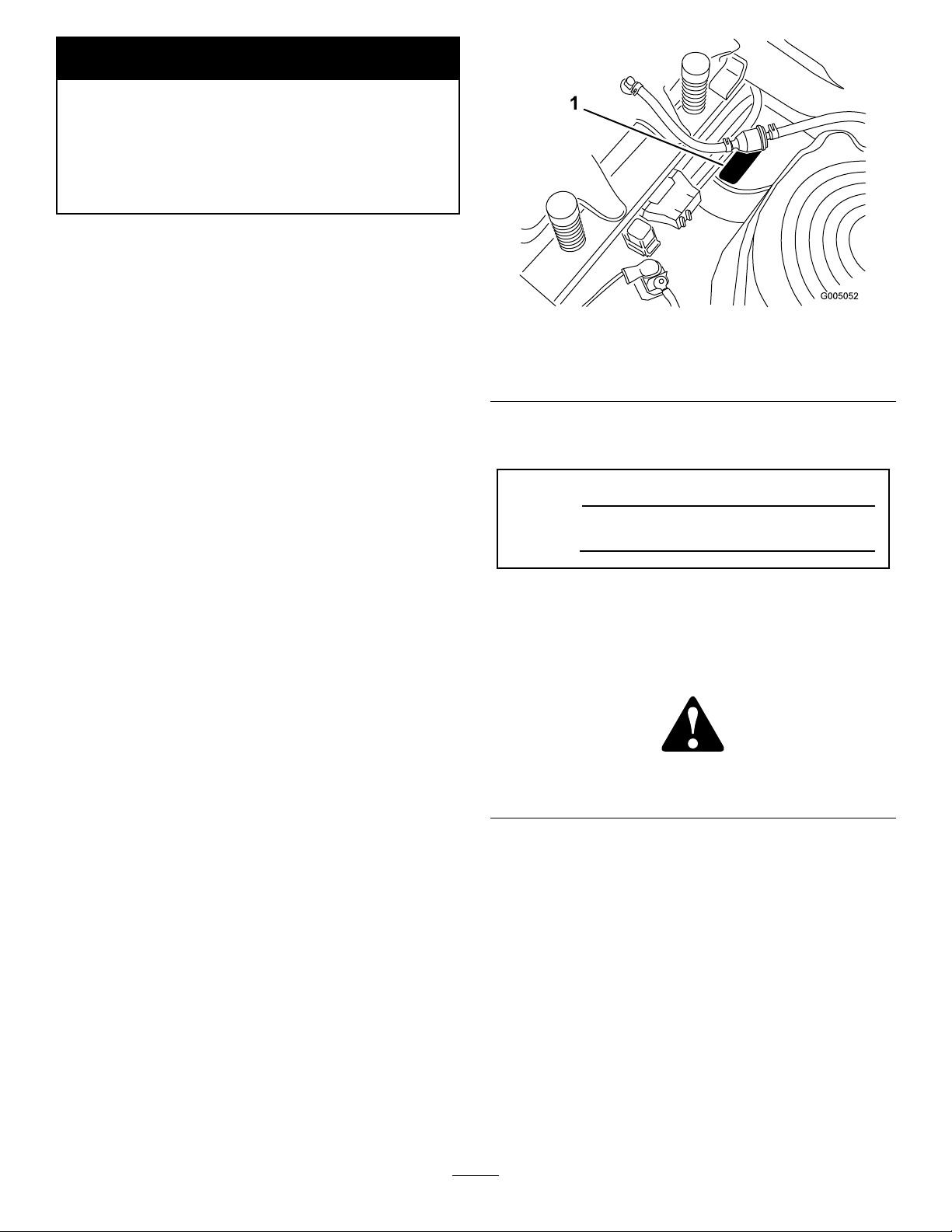
Figure1
Undertheseat
ThissparkignitionsystemcomplieswithCanadian
ICES-002.
Theenclosed
Engine Owner’ s Man ual
issupplied
forinformationregardingtheUSEnvironmental
ProtectionAgency(EPA)andtheCalifornia
EmissionControlRegulationofemissionsystems,
maintenance,andwarranty.Replacementsmaybe
orderedthroughtheenginemanufacturer.
Formodelswithstatedenginehorsepower,thegross
horsepoweroftheenginewaslaboratoryratedbythe
enginemanufacturerinaccordancewithSAEJ1940.
Asconguredtomeetsafety,emission,andoperating
requirements,theactualenginehorsepoweronthisclass
oflawnmowerwillbesignicantlylower.
Introduction
Readthisinformationcarefullytolearnhowtooperate
andmaintainyourproductproperlyandtoavoidinjury
andproductdamage.Youareresponsibleforoperating
theproductproperlyandsafely.
YoumaycontactTorodirectlyatwww .Toro.comfor
productandaccessoryinformation,helpndinga
dealer,ortoregisteryourproduct.
1.Modelandserialnumberplate
Writetheproductmodelandserialnumbersinthespace
below:
ModelNo.
SerialNo.
Thismanualidentiespotentialhazardsandhas
safetymessagesidentiedbythesafetyalertsymbol
(Figure2),whichsignalsahazardthatmaycauseserious
injuryordeathifyoudonotfollowtherecommended
precautions.
Figure2
1.Safetyalertsymbol.
Thismanualusestwootherwordstohighlight
information.Importantcallsattentiontospecial
mechanicalinformationandNoteemphasizesgeneral
informationworthyofspecialattention.
Wheneveryouneedservice,genuineToroparts,or
additionalinformation,contactanAuthorizedService
DealerorToroCustomerServiceandhavethemodel
andserialnumbersofyourproductready .Figure1
identiesthelocationofthemodelandserialnumbers
ontheproduct.Writethenumbersinthespace
provided.
©2008—TheToro®Company
8111LyndaleAvenueSouth
Bloomington,MN55420
Contents
Introduction.................................................................2
Safety...........................................................................3
SafeOperatingPractices.......................................3
ToroRidingMowerSafety....................................5
SlopeChart..........................................................7
SafetyandInstructionalDecals.............................8
ProductOverview......................................................12
Contactusatwww.Toro.com.
2
PrintedintheUSA.
AllRightsReserved
Page 3

Controls.............................................................13
Operation...................................................................14
ThinkSafetyFirst...............................................14
RecommendedGasoline.....................................14
CheckingtheEngineOilLevel............................16
StartingtheEngine.............................................16
OperatingtheBlades..........................................17
StoppingtheEngine...........................................18
TheSafetyInterlockSystem................................18
DrivingForwardorBackward.............................19
StoppingtheMachine.........................................20
AdjustingtheHeightofCut................................20
PositioningtheSeat............................................20
AdjustingtheMotionControlLevers..................20
PushingtheMachinebyHand.............................21
GrassDeector..................................................22
OperatingTips...................................................22
Maintenance...............................................................24
RecommendedMaintenanceSchedule(s)................24
PremaintenanceProcedures....................................25
RaisingtheSeat..................................................25
AccessingtheBattery.........................................25
Lubrication.............................................................25
GreasingtheBearings.........................................25
EngineMaintenance...............................................26
ServicingtheAirCleaner....................................26
ServicingtheEngineOil.....................................27
ServicingtheSparkPlug.....................................29
CleaningtheBlowerHousing..............................29
FuelSystemMaintenance.......................................30
ReplacingtheFuelFilter.....................................30
ElectricalSystemMaintenance................................31
ChargingtheBattery...........................................31
ServicingtheFuses.............................................32
DriveSystemMaintenance.....................................33
CheckingtheTirePressure.................................33
MowerMaintenance...............................................34
ServicingtheCuttingBlades...............................34
LevelingtheMowerDeck...................................36
RemovingtheMower.........................................38
MowerBeltMaintenance....................................39
InstallingtheMower...........................................40
ReplacingtheGrassDeector.............................40
Cleaning.................................................................41
WashingtheUndersideoftheMower..................41
Storage.......................................................................42
CleaningandStorage..........................................42
Troubleshooting.........................................................44
Schematics.................................................................46
Safety
ThismachinemeetsorexceedstheB71.1-2003
specicationsoftheAmericanNationalStandards
Institute,ineffectatthetimeofproduction.
However,improperuseormaintenancebythe
operatororownercanresultininjury.Toreduce
thepotentialforinjury,complywiththesesafety
instructionsandalwayspayattentiontothe
safetyalertsymbol,whichmeansCAUTION,
WARNING,orDANGER-"personalsafety
instruction."Failuretocomplywiththeinstruction
mayresultinpersonalinjuryordeath.
SafeOperatingPractices
ThefollowinginstructionsarefromANSIstandard
B71.1-2003.
Thisproductiscapableofamputatinghandsand
feetandthrowingobjects.Alwaysfollowallsafety
instructionstoavoidseriousinjuryordeath.
GeneralOperation
•Read,understand,andfollowallinstructionsin
theoperator’smanualandonthemachinebefore
starting.
•Donotplacehandsorfeetnearrotatingpartsor
underthemachine.Keepclearofthedischarge
openingatalltimes.
•Allowonlyresponsibleadultswhoarefamiliarwith
theinstructionstooperatethemachine.
•Cleartheareaofobjectssuchasrocks,toys,wire,
etc.,whichcouldbepickedupandthrownbythe
blade.
•Besuretheareaisclearofotherpeoplebefore
mowing.Stopthemachineifanyoneentersthearea.
•Nevercarrypassengers.
•Donotmowinreverseunlessabsolutelynecessary.
Alwayslookdownandbehindbeforeandwhile
backingup.
•Beawareofthemowerdischargedirectionanddo
notpointitatanyone.Avoiddischargingmaterial
againstawallorobstruction.Materialmayricochet
backtowardtheoperator.Stoptheblade(s)when
crossinggravelsurfaces.
•Donotoperatethemachinewithoutdeector,
dischargecoverorentiregrasscollectionsystemin
placeandworking.
•Bealert,slowdownandusecautionwhenmaking
turns.Lookbehindandtothesidebeforechanging
directions.
3
Page 4

•Neverleavearunningmachineunattended.Always
turnoffblades,setparkingbrake,stopengine,and
removekeybeforedismounting.
•Turnoffbladeswhennotmowing.Stoptheengine
andwaitforallpartstocometoacompletestop
beforecleaningthemachine,removingthegrass
catcheroruncloggingthedischargechute.
•Operatethemachineonlyindaylightorgood
articiallight.
•Avoidsuddenstartswhenmowinguphillbecause
themowermaytipbackwards.
•Beawarethatlossoftractionmayoccurgoing
downhill.Weighttransfertothefrontwheelsmay
causedrivewheelstoslipandcauselossofbraking
andsteering.
•Alwaysavoidsuddenstartingorstoppingona
slope.Iftireslosetraction,disengagethebladesand
proceedslowlyofftheslope.
•Donotoperatethemachinewhileunderthe
inuenceofalcoholordrugs.
•Watchfortrafcwhenoperatingnearorcrossing
roadways.
•Useextracarewhenloadingorunloadingthe
machineintoatrailerortruck.
•Alwaysweareyeprotectionwhenoperatingthe
mower.
•Dataindicatesthatoperators,age60yearsand
above,areinvolvedinalargepercentageofriding
mower-relatedinjuries.Theseoperatorsshould
evaluatetheirabilitytooperatetheridingmower
safelyenoughtoprotectthemselvesandothersfrom
seriousinjury.
•Alwaysfollowtherecommendationsforwheel
weightsorcounterweights.
SlopeOperation
Slopesareamajorfactorrelatedtolossofcontroland
tip-overaccidents,whichcanresultinsevereinjuryor
death.Operationonallslopesrequiresextracaution.If
youcannotbackuptheslopeorifyoufeeluneasyonit,
donotmowit.
•Donotmowslopesgreaterthan15degrees.
•Watchforditches,holes,rocks,dips,andrisesthat
changetheoperatingangle,asroughterraincould
overturnthemachine.
•Choosealowgroundspeedsoyouwillnothaveto
stopwhileoperatingonaslope.
•Donotmowslopeswhengrassiswet.Slippery
conditionsreducetractionandcouldcausesliding
andlossofcontrol.
•Alwayskeepthewheelmotorsengagedwhengoing
downslopes.
•Reducespeedanduseextremecautiononslopes.
•Donotmakesuddenturnsorrapidspeedchanges.
•Useextremecarewithgrasscatchersorother
attachments.Thesecanchangethestabilityofthe
machineandcauselossofcontrol.
•Donottrytostabilizethemachinebyputtingyour
footontheground.
•Donotmowneardrop-offs,ditches,steepbanks
orwater.Wheelsdroppingoveredgescancause
rollovers,whichmayresultinseriousinjury,death
ordrowning.
•Useawalkbehindmowerand/orahandtrimmer
neardrop-offs,ditches,steepbanksorwater.
Children
Tragicaccidentscanoccuriftheoperatorisnotalertto
thepresenceofchildren.Childrenareoftenattractedto
themachineandthemowingactivity.Neverassumethat
childrenwillremainwhereyoulastsawthem.
•Keepchildrenoutofthemowingareaandunder
thewatchfulcareofanotherresponsibleadult,not
theoperator.
•Bealertandturnthemachineoffifchildrenenter
thearea.
•Beforeandwhilebackingorchangingdirection,look
behind,down,andside-to-sideforsmallchildren.
•Nevercarrychildren,evenwiththebladesoff.They
mayfalloffandbeseriouslyinjuredorinterferewith
safemachineoperation.
•Childrenwhohavebeengivenridesinthepastmay
suddenlyappearinthemowingareaforanotherride
andberunoverorbackedoverbythemower.
•Neverallowchildrentooperatethemachine.
•Useextracarewhenapproachingblindcorners,
shrubs,trees,theendofafenceorotherobjectsthat
mayobscurevision.
Towing
•Removeormarkobstaclessuchasrocks,treelimbs,
etc.fromthemowingarea.Tallgrasscanhide
obstacles.
Ahitchkitisavailableforthismachineandcanbe
obtainedbycontactinganAuthorizedToroDealer.
Donottowwithoutrstinstallingthismanufacturer
4
Page 5

approvedhitch.Thefollowingguidelinesapplywhen
towingwiththeapprovedhitchkitinstalled.
•Towonlywithamachinethathasahitchdesigned
fortowing.Donotattachtowedequipmentexcept
atthehitchpoint.
•Followthemanufacturer’srecommendationfor
weightlimitsfortowedequipmentandtowingon
slopes.
•Neverallowchildrenorothersinorontowed
equipment.
•Onslopes,theweightofthetowedequipmentmay
causelossoftractionandlossofcontrol.
•Travelslowlyandallowextradistancetostop.
•Keepnutsandboltstight,especiallytheblade
attachmentbolts.Keepequipmentingood
condition.
•Nevertamperwithsafetydevices.Checktheir
properoperationregularly.
•Keepthemachinefreeofgrass,leaves,orother
debrisbuild-up.Cleanupoilorfuelspillagefuel
soakeddebris.Allowthemachinetocoolbefore
storing.
•Stopandinspecttheequipmentifyoustrikean
object.Repair,ifnecessary,beforerestarting.
•Nevermakeanyadjustmentsorrepairswiththe
enginerunning.
Service
SafeHandlingofGasoline:
Toavoidpersonalinjuryorpropertydamage,useextra
carewhenhandlinggasolineandotherfuels.Theyare
ammableandthevaporsareexplosive.
•Extinguishallcigarettes,cigars,pipesandother
sourcesofignition.
•Useonlyanapprovedcontainer.
•Neverremovethegascaporaddfuelwhenthe
engineisrunning.Allowtheenginetocoolbefore
refueling.
•Neverrefuelthemachineindoors.
•Neverstorethemachineorfuelcontainerinside
wherethereisanopename,suchasnearawater
heaterorfurnace.
•Neverllcontainersinsideavehicleoronatruckor
trailerwithaplasticliner.Alwaysplacecontainerson
thegroundawayfromyourvehiclebeforelling.
•Removegas-poweredequipmentfromthetruck
ortrailerandrefuelitontheground.Ifthisisnot
possible,thenrefuelsuchequipmentwithaportable
container,ratherthanfromagasolinedispenser
nozzle.
•Keepthenozzleincontactwiththerimofthefuel
tankorcontaineropeningatalltimesuntilthefueling
iscomplete.Donotuseanozzlelock-opendevice.
•Iffuelisspilledonclothing,changeclothing
immediately.
•Neveroverllthefueltank.Replacegascapand
tightensecurely .
GeneralService:
•Neveroperateamachineinsideaclosedarea.Engine
exhaustcontainscarbonmonoxide,whichisan
odorless,deadlypoisonthatcankillyou.
•Grasscatchercomponentsaresubjecttowear,
damageanddeterioration,whichcouldexpose
movingpartsorallowobjectstobethrown.
Frequentlycheckcomponentsandreplacewith
manufacturers’recommendedparts,whennecessary.
•Mowerbladesaresharpandcancut.Wrapthe
blade(s)orweargloves,anduseextracautionwhen
servicingthem.
•Checkforproperbrakeoperationfrequently.Adjust
andserviceasrequired.
•Maintainorreplacesafetyandinstructiondecalsas
necessary.
•UseonlygenuineTororeplacementpartstoensure
thatoriginalstandardsaremaintained.
ToroRidingMowerSafety
Thefollowinglistcontainssafetyinformationspecicto
Toroproductsorothersafetyinformationthatyoumust
knowthatisnotincludedintheANSIstandards.
•Stoptheengine,disconnectsparkplugwire(s)and
removekeybeforeperforminganyservice,repairs,
maintenanceoradjustments.
•Keephands,feet,hair,andlooseclothingawayfrom
attachmentdischargearea,undersideofmowerand
anymovingpartswhileengineisrunning.
•Donottouchequipmentorattachmentpartswhich
maybehotfromoperation.Allowtocoolbefore
attemptingtomaintain,adjustorservice.
•Batteryacidispoisonousandcancauseburns.Avoid
contactwithskin,eyes,andclothing.Protectyour
face,eyes,andclothingwhenworkingwithabattery.
•Batterygasescanexplode.Keepcigarettes,sparks
andamesawayfrombattery.
5
Page 6

•UseonlyToroapprovedattachments.Warrantymay
bevoidedifusedwithunapprovedattachments.
•Ifloadingthemachineontoatrailerortruck,usea
single,full-widthramponly.Therampangleshould
notexceed15degrees.
Note:Determinetheleftandrightsidesofthe
machinefromthenormaloperatingposition.
6
Page 7
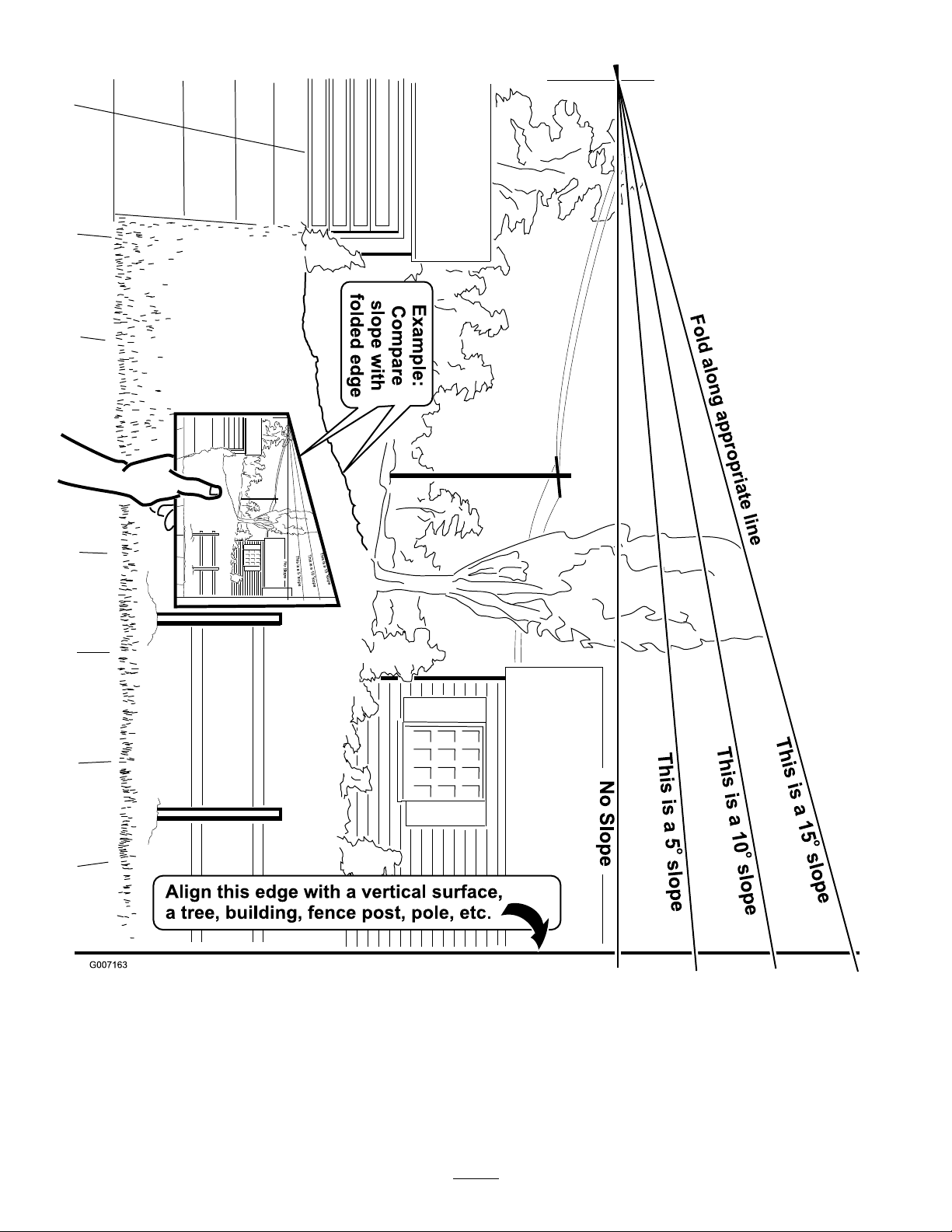
SlopeChart7SafetyandInstructional
Decals
Page 8
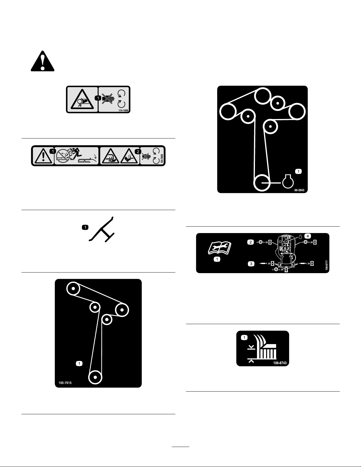
Safetydecalsandinstructionsareeasilyvisibletotheoperatorandarelocatednearanyareaof
potentialdanger.Replaceanydecalthatisdamagedorlost.
114-1606
1.Entanglementhazard,belt—keepallguardsinplace.
93-7009
1.Warning—don’toperatethemowerwiththedeectorupor
removed;keepthedeectorinplace.
2.Cutting/dismembermenthazardofhandorfoot,mower
blade—stayawayfrommovingparts.
99-3943
ForModelswith50InchDecks
1.Engine
Manufacturer’sMark
1.Indicatesthebladeisidentiedasapartfromtheoriginal
machinemanufacturer.
105-7015
ForModelswith42InchDecks
106-8717
1.Readtheinstructionsbeforeservicingorperforming
maintenance.
2.Checktirepressureevery25operatinghours.
3.Greaseevery25operatinghours.
4.Engine
106-8743
1.Heightofcut
8
Page 9
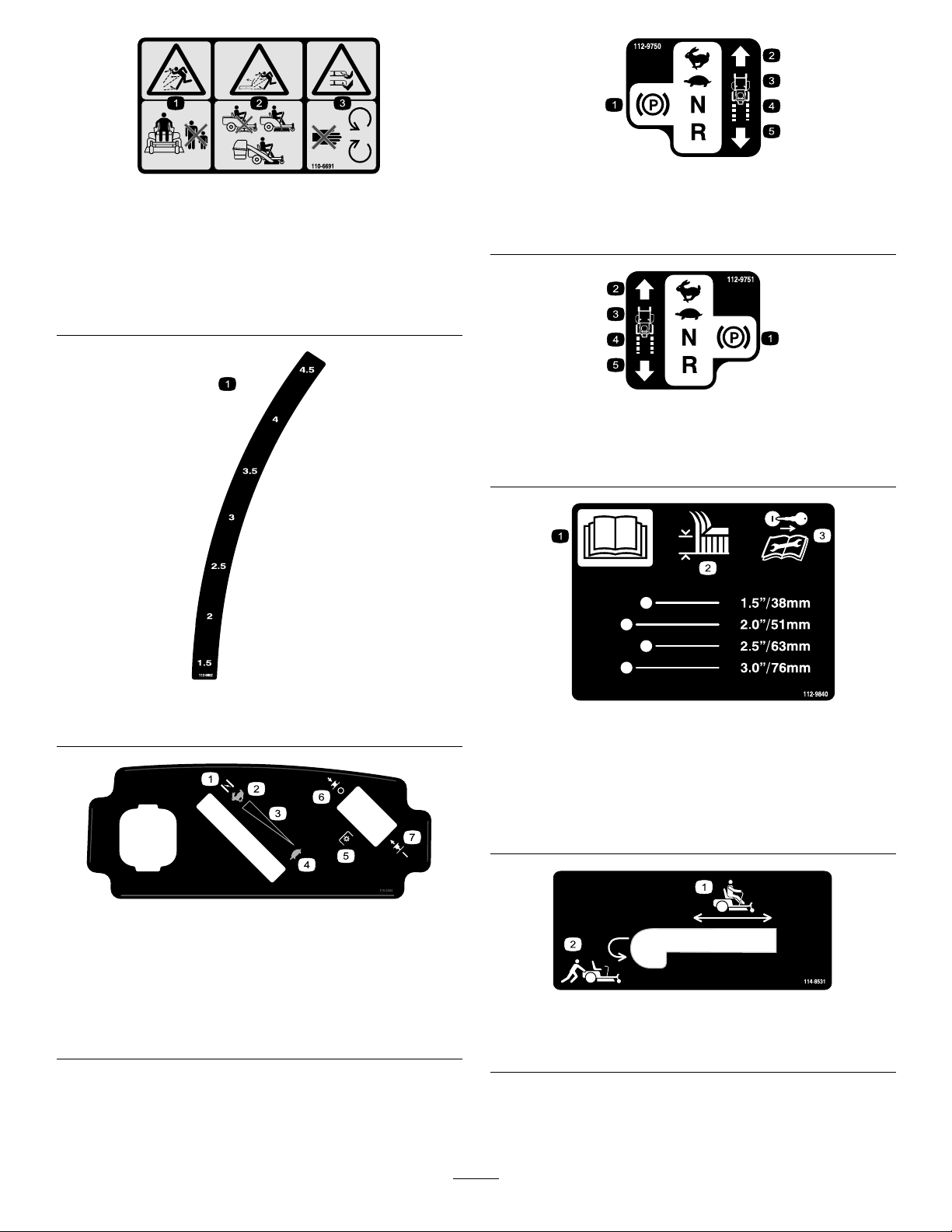
110-6691
1.Thrownobjecthazard—keepbystandersasafedistance
fromthemachine.
2.Thrownobjecthazard,mower—donotoperatethewithout
deector,dischargecoverorgrasscollectionsystemin
place.
3.Cutting/dismembermentofhandorfoot—stayawayfrom
movingparts.
112-9750
1.Parkingposition4.Neutral
2.Fast5.Reverse
3.Slow
112-9751
1.Parkingposition4.Neutral
2.Fast5.Reverse
3.Slow
112-9802
1.Height-of-cut
115-2500
1.Choke5.Powertake-off(PTO),
2.Fast
3.Continuousvariable
setting
4.Slow
Bladecontrolswitchon
somemodels
6.Bladecontrolswitch—Off
7.Bladecontrolswitch—On
ForModelswith50InchDecks
1.ReadtheOperator’s
Manual.
2.Heightofcut
1.Bypassleverpositionfor
operatingthemachine
112-9840
3.Removetheignitionkey
andreadtheinstructions
beforeservicingor
performingmaintenance.
114-8531
2.Bypassleverpositionfor
pushingthemachine
9
Page 10
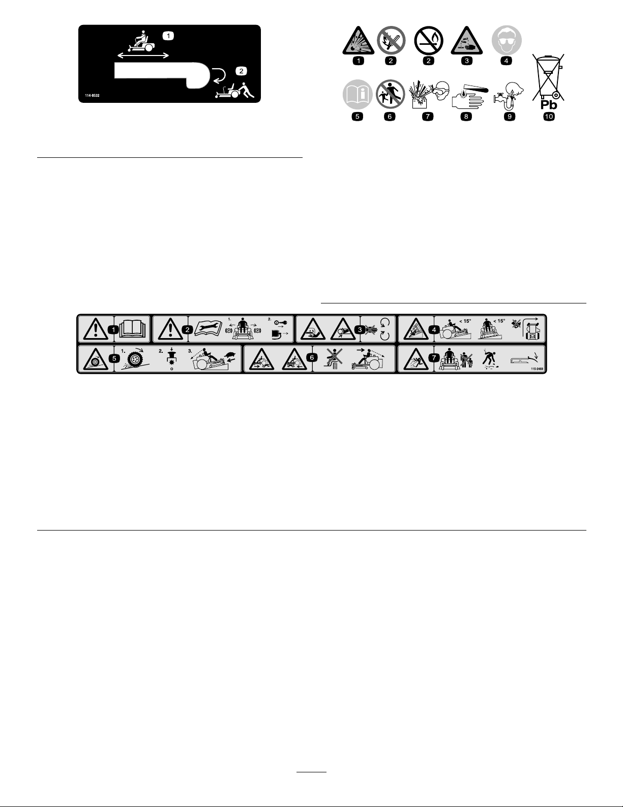
114-8532
1.Bypassleverpositionfor
operatingthemachine
2.Bypassleverpositionfor
pushingthemachine
BatterySymbols
Someorallofthesesymbolsareonyourbattery
1.Explosionhazard
2.Nore,opename,or
smoking.
3.Causticliquid/chemical
burnhazard
4.Weareyeprotection9.Flusheyesimmediately
5.ReadtheOperator’s
Manual.
6.Keepbystandersasafe
7.Weareyeprotection;
8.Batteryacidcancause
10.Containslead;donot
distancefromthebattery.
explosivegasescan
causeblindnessandother
injuries
blindnessorsevereburns.
withwaterandgetmedical
helpfast.
discard.
115-2469
1.Warning—readtheOperator’sManual.
2.Warning—readtheinstructionsbeforeservicingorperformingmaintenance;movethemotioncontrolleverstothepark(brake)
position,removetheignitionkeyanddisconnectthesparkplugwire.
3.Cutting/dismembermenthazard,mowerblade;entanglementhazard,belt—donotopenorremovesafetyshieldswhileengineis
running.
4.Tippinghazard—donotmowslopesgreaterthan15degrees,avoidsuddenandsharpturnswhileonslopes.
5.Lossoftraction/controlhazard,slopes—lossoftraction/controlonaslope,disengagethebladecontrolswitch(PTO),proceed
offtheslopeslowly.
6.Crushing/dismembermenthazardofbystanders,reversing;crushing/dismembermenthazardofbystanders—donotcarry
passengers,lookbehindanddownwhenreversing.
7.Thrownobjecthazard—keepbystandersasafedistancefromthemachine,pickupdebrisbeforeoperating,keepdeectorinplace.
10
Page 11

1.Fuelgauge2.Full
1.Fuelgauge2.Full
115-2450
3.Half
4.Empty
115-2489
3.Half
4.Empty
1.Fuelgauge2.Full
115-2451
3.Half
4.Empty
11
Page 12
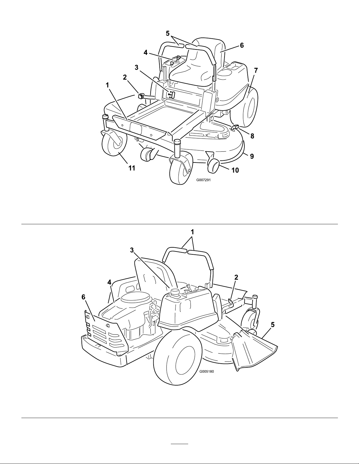
ProductOverview
G005180
1
2
3
4
5
6
1.Footrest
2.Heightofcutlever
3.Fuelgauge
4.Controlpanel
5.Motioncontrollevers
6.Operatorseat
Figure3
7.Reardrivewheel10.Anti-scalproller
8.Washouttting
9.Mowerdeck
11.Frontcasterwheel
Figure4
1.Motioncontrollevers
2.Heightofcutlever
3.Gastankcap5.Deector
4.Engine
12
6.Engineguard(Model74370only)
Page 13
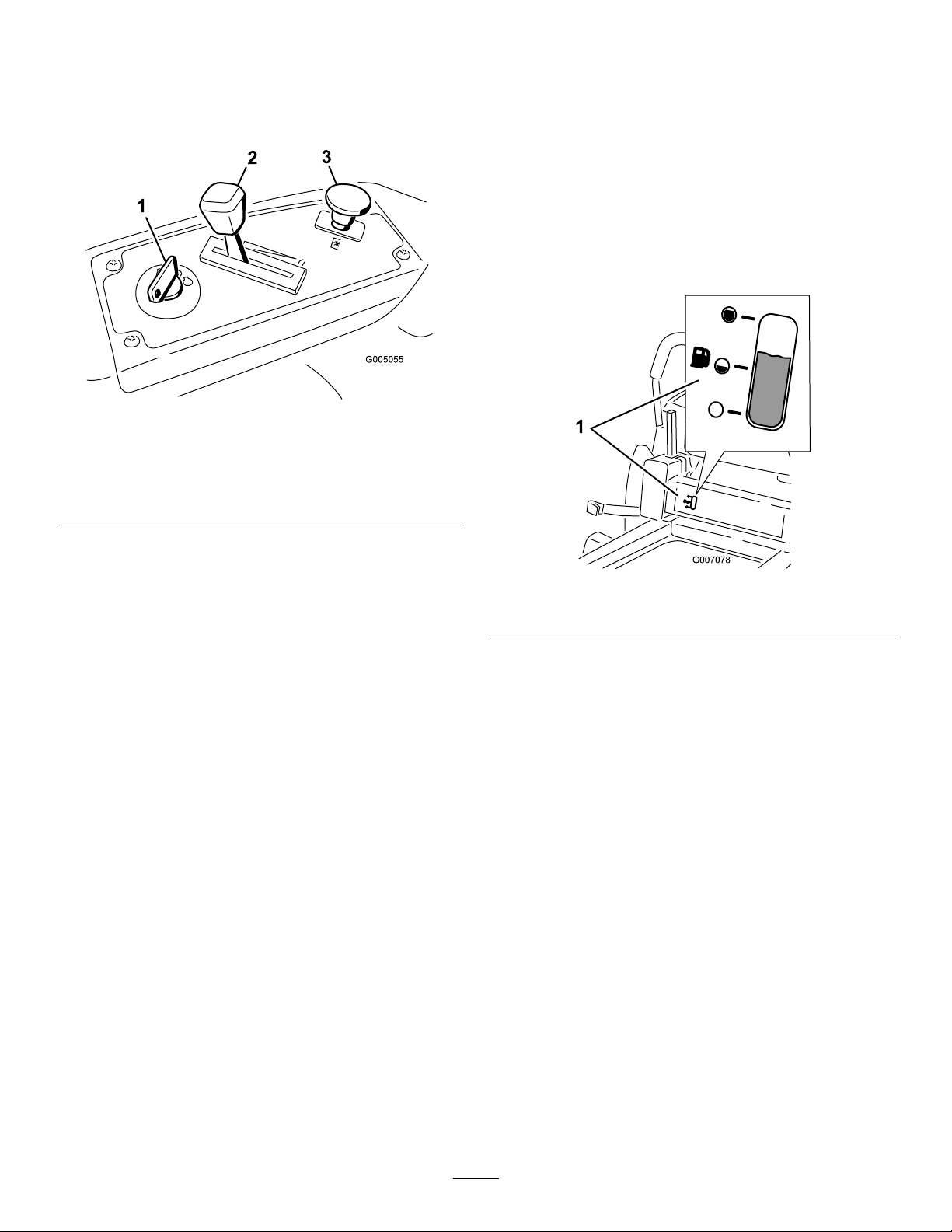
Controls
G005055
1
2
3
BecomefamiliarwithallofthecontrolsinFigure3,
Figure4,andFigure5beforeyoustarttheengineand
operatethemachine.
Figure5
ControlPanel
reverse;wheelspeedisproportionaltotheamountthe
leverismoved.Movethecontrolleversoutwardfrom
thecentertotheparkpositionandexitthemachine
(Figure15).Alwayspositionthemotioncontrollevers
intotheparkpositionwhenyoustopthemachineor
leaveitunattended.
FuelGauge
Thefuelwindowlocatedbelowtheoperatorposition
canbeusedtoverifythelevelofgasolineinthetank
(Figure6).
1.Ignitionswitch3.Bladecontrolswitch
(powertake-off)
2.Throttle/Choke
IgnitionSwitch
Theignitionswitchhasthreepositions,Off,Runand
Start.ThekeywillturntoStartandmovebackto
Runuponrelease.TurningthekeytotheOffposition
willstoptheengine;however,alwaysremovethekey
whenleavingthemachinetopreventsomeonefrom
accidentallystartingtheengine(Figure5).
Throttle/ChokeControl
Thethrottleandchokeiscombinedintoonecontrol
lever.Thethrottlecontrolstheenginespeedandithasa
continuousvariablesettingfromSlowtoFast.Engage
thechokebymovingtheleverpasttheFastsettinguntil
itstops(Figure5).
BladeControlSwitch(PowerTake-Off)
Figure6
1.Fuelgaugewindow
Height-of-CutLever
Theheightofcutleverallowstheoperatortolower
andraisethedeckfromtheseatedposition.Whenthe
leverismovedup,towardtheoperatorthedeckisraised
fromthegroundandwhenmoveddown,awayfromthe
operatoritisloweredtowardtheground.Onlyadjustthe
heightofcutwhilemachineisnotmoving(Figure18).
Thebladecontrolswitch,representedbyapower
take-off(PTO)symbol,engagesanddisengagespower
tothemowerblades(Figure5).
MotionControlLeversandPark
Position
Themotioncontrolleversarespeedsensitivecontrolsof
independentwheelmotors.Movingaleverforwardor
backwardturnsthewheelonthesamesideforwardorin
13
Page 14
Operation
Note:Determinetheleftandrightsidesofthe
machinefromthenormaloperatingposition.
ThinkSafetyFirst
Pleasecarefullyreadallofthesafetyinstructionsand
decalsinthesafetysection.Knowingthisinformation
couldhelpyou,yourfamily,petsorbystandersavoid
injury.
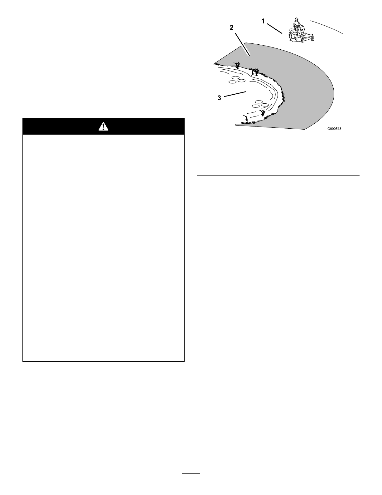
Mowingonwetgrassorsteepslopescancause
slidingandlossofcontrol.
Wheelsdroppingoveredgescancauserollovers,
whichmayresultinseriousinjury,deathor
drowning.
Alossoftractionisalossofsteeringcontrol.
Toavoidlossofcontrolandpossibilityof
rollover:
•Donotmowneardrop-offsornearwater.
•Donotmowslopesgreaterthan15degrees.
•Reducespeedanduseextremecautionon
slopes.
•Whenmowingslopes,graduallyworkfrom
lowertohigherareasontheincline.
•Avoidsuddenturnsorrapidspeedchanges.
•Turnup,intoaninclinewhenchanging
directionsonslopes.Turningdownthe
slopereducestraction.
Figure7
1.SafeZone-usetheTimeCutterhere
2.Usewalkbehindmowerand/orhandtrimmerneardrop-offs
andwater.
3.Water
RecommendedGasoline
UseUNLEADEDRegularGasolinesuitablefor
automotiveuse(87pumpoctaneminimum).Leaded
regulargasolinemaybeusedifunleadedregularisnot
available.
Important:Neverusemethanol,gasoline
containingmethanol,orgasoholcontainingmore
than10percentethanolbecausethefuelsystem
couldbedamaged.Donotmixoilwithgasoline.
•Attachmentschangethehandling
characteristicsofthemachine.Useextra
cautionwhenusingattachmentswiththe
machine.
14
Page 15
Incertainconditions,gasolineisextremely
ammableandhighlyexplosive.Areor
explosionfromgasolinecanburnyouand
othersandcandamageproperty.
•Fillthefueltankoutdoors,inanopenarea,
whentheengineiscold.Wipeupany
gasolinethatspills.
Incertainconditionsduringfueling,static
electricitycanbereleasedcausingaspark
whichcanignitethegasolinevapors.Are
orexplosionfromgasolinecanburnyouand
othersandcandamageproperty.
•Alwaysplacegasolinecontainersonthe
groundawayfromyourvehiclebeforelling.
•Neverllthefueltankinsideanenclosed
trailer.
•Donotllthefueltankcompletelyfull.Add
gasolinetothefueltankuntilthebodyof
thetankisfullbutfueldoesnotlltheneck
ofthetank.Thisemptyspaceinthetank
allowsgasolinetoexpand.
•Neversmokewhenhandlinggasoline,and
stayawayfromanopenameorwhere
gasolinefumesmaybeignitedbyaspark.
•Storegasolineinanapprovedcontainerand
keepitoutofthereachofchildren.Never
buymorethana30-daysupplyofgasoline.
•Donotoperatewithoutentireexhaust
systeminplaceandinproperworking
condition.
•Donotllgasolinecontainersinsidea
vehicleoronatruckortrailerbedbecause
interiorcarpetsorplastictruckbedliners
mayinsulatethecontainerandslowtheloss
ofanystaticcharge.
•Whenpractical,removegas-powered
equipmentfromthetruckortrailerand
refueltheequipmentwithitswheelsonthe
ground.
•Ifthisisnotpossible,thenrefuelsuch
equipmentonatruckortrailerfroma
portablecontainer,ratherthanfroma
gasolinedispensernozzle.
•Ifagasolinedispensernozzlemustbeused,
keepthenozzleincontactwiththerimof
thefueltankorcontaineropeningatall
timesuntilfuelingiscomplete.
Gasolineisharmfulorfatalifswallowed.
Long-termexposuretovaporscancauseserious
injuryandillness.
•Avoidprolongedbreathingofvapors.
•Keepfaceawayfromnozzleandgastankor
conditioneropening.
•Keepgasawayfromeyesandskin.
UsingStabilizer/Conditioner
Useafuelstabilizer/conditionerinthemachineto
providethefollowingbenets:
•Keepsgasolinefreshduringstorageof30daysor
less.Forlongerstorageitisrecommendedthatthe
fueltankbedrained.
•Cleanstheenginewhileitruns.
•Eliminatesgum-likevarnishbuildupinthefuel
system,whichcauseshardstarting.
15
Page 16

Addthecorrectamountofgasstabilizer/conditioner
G005302
1
2
3
4
1
2
G005056
1
2
tothegas.
allowsgasolinetoexpand.Donotllthefueltank
completelyfull.
Note:Afuelstabilizer/conditionerismosteffective
whenmixedwithfreshgasoline.Tominimizethe
chanceofvarnishdepositsinthefuelsystem,usefuel
stabilizeratalltimes.
Gasoline/Alcoholblends
Gasohol(upto10percentethylalcohol,90percent
unleadedgasolinebyvolume)isapprovedforfueluse
bytheenginemanufacturer.Othergasoline/alcohol
blends,suchasE85,arenotapproved.
Gasoline/Etherblends
MethylTertiaryButylEther(MTBE)andunleaded
gasolineblends(uptoamaximumof15percentMTBE
byvolume)areapprovedforfuelusebytheengine
manufacturer.Othergasoline/etherblendsarenot
approved.
FuelGauge
Usethefuelwindowbelowtheoperatortoverifythe
levelofgasolinebeforellingthetank(Figure8).
4.Installthefueltankcapsecurely.Wipeupany
gasolinethatmayhavespilled.
Figure9
1.Gastankbody
2.Gastankneck4.Gastankopening
3.Filltohere,approximately
CheckingtheEngineOilLevel
Figure8
1.Fuelgaugewindow
FillingtheFuelTank
1.Shuttheengineoffandsetthemotioncontrolsto
theparkposition.Raisetheseatsothegastankis
visiblewhilefueling.
2.Cleanaroundthefueltankcapandremovethecap.
3.Addunleadedregulargasolineuntilthebodyofthe
tankisfullbutfueldoesnotlltheneckofthe
tank(Figure9).Thisspaceintheneckofthetank
Beforeyoustarttheengineandusethemachine,check
theoillevelintheenginecrankcase;refertoChecking
theOilLevelintheEngineMaintenancesection.
StartingtheEngine
1.Sitdownontheseatandmovethemotioncontrols
outwardtotheparkposition.
2.Disengagethebladesbymovingthebladecontrol
switchtoOff(Figure10).
Figure10
1.Controlpanel2.Bladecontrolswitch—Off
position
16
Page 17

3.MovethethrottlelevertoChokebeforestartinga
1
2
2
3
4
5
6
G005057
1
2
2
3
4
5
6
1
2
3
4
5
6
G005058
1
2
3
4
5
6
coldengine(Figure11).
Note:Awarmorhotenginemaynotrequire
choking.
Figure12
1.Controlpanel4.Off
2.Ignitionkey—runposition5.Run
3.Ignitionkey—startposition
6.Start
5.Aftertheenginestarts,movethethrottleleverto
Fast(Figure11).Iftheenginestallsorhesitates,
movethethrottleleverbacktoChokeforafew
seconds.Repeatthisasrequired.
Figure11
1.Controlpanel
2.Throttle/choke
lever—chokeposition
3.Choke6.Slow
4.Fast
5.Continuousvariable
setting
4.TurntheignitionkeytoStarttoenergizethestarter.
Whentheenginestarts,releasethekey(Figure12).
Important:Donotengagethestarterformore
than10secondsatatime.Iftheenginefails
tostart,allowa60secondcool-downperiod
betweenattempts.Failuretofollowthese
instructionscandamagethestartermotor.
OperatingtheBlades
Thebladecontrolswitch,representedbyapower
take-off(PTO)symbol,engagesanddisengagespower
tothemowerblades.Thisswitchcontrolspowertoany
attachmentsthatdrawpowerfromtheengine,including
themowerdeckandcuttingblades.
EngagingtheBlades
Important:Donotengagethebladeswhen
parkedintallgrass.Beltorclutchdamagecan
occur.
1.Releasepressureonthemotioncontrolleversand
placethemachineinneutral.
2.MovethethrottletotheFastposition.
Note:Alwaysengagethebladeswiththethrottle
intheFastposition.
3.Pulluponthebladecontrolswitchtomoveitto
theOnpositionandengagetheblades(Figure13).
17
Page 18

G005059
121
2
Figure13
1
2
G005056
1
2
1.Controlpanel2.Bladecontrolswitch—On
position
TheSafetyInterlockSystem
Ifsafetyinterlockswitchesaredisconnected
ordamagedthemachinecouldoperate
unexpectedlycausingpersonalinjury.
•Donottamperwiththeinterlockswitches.
•Checktheoperationoftheinterlock
switchesdailyandreplaceanydamaged
switchesbeforeoperatingthemachine.
UnderstandingtheSafetyInterlock
System
DisengagingtheBlades
Pushdownonthebladecontrolswitchtomoveitto
theOffpositionanddisengagetheblades(Figure14).
Figure14
1.Controlpanel2.Bladecontrolswitch—Off
StoppingtheEngine
1.Disengagethebladesbymovingthebladecontrol
switchtoOff(Figure14).
2.MovethethrottlelevertobetweenFastandhalf
throttle(Figure12).
3.TurntheignitionkeytoOff(Figure11)andremove
thekey .
Thesafetyinterlocksystemisdesignedtopreventthe
enginefromstartingunless:
•Thebladesaredisengaged.
•Themotioncontrolleversareintheparkposition.
Thesafetyinterlocksystemalsoisdesignedtostop
theenginewhenthecontrolleversareoutofthepark
positionandyourisefromtheseatwhentheblades
areengaged.
TestingtheSafetyInterlockSystem
Testthesafetyinterlocksystembeforeyouusethe
machineeachtime.Ifthesafetysystemdoesnot
operateasdescribedbelow ,haveanAuthorizedService
Dealerrepairthesafetysystemimmediately .
1.Whilesittingontheseat,withthecontrolleversin
parkposition,andmovethebladecontrolswitch
toOn.Trystartingtheengine;theengineshould
notcrank.
2.Whilesittingontheseat,movethebladecontrol
switchtoOff.Moveeithermotioncontrollever
tothecenter,unlockedposition.Trystartingthe
engine;theengineshouldnotcrank.Repeatwith
theothermotioncontrollever.
3.Whilesittingontheseat,movethebladecontrol
switchtoOff,andlockthemotioncontrolleversin
theparkposition.Starttheengine.Whiletheengine
isrunning,engagethebladecontrolswitch,andrise
slightlyfromtheseat;theengineshouldstop.
4.Whilesittingontheseat,movethebladecontrol
switchtoOff,andlockthemotioncontrollevers
intheparkposition.Starttheengine.Whilethe
engineisrunning,movethemotioncontrollevers
tothecenter,unlockedposition,engagetheblade
controlswitch,andriseslightlyfromtheseat;the
engineshouldstop.
18
Page 19
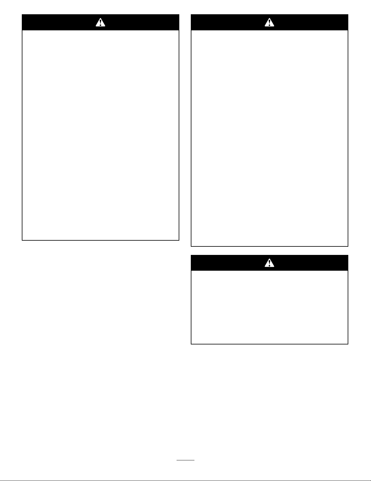
DrivingForwardorBackward
G008952
G008953
Thethrottlecontrolregulatestheenginespeedas
measuredinrpm(revolutionsperminute).Place
thethrottlecontrolintheFastpositionforbest
performance.Alwaysoperateinthefullthrottle
position.
Themachinecanspinveryrapidly .The
operatormaylosecontrolofthemachine
andcausepersonalinjuryordamagetothe
machine.
•Usecautionwhenmakingturns.
•Slowthemachinedownbeforemaking
sharpturns.
Figure16
Togostraight,applyequalpressuretobothmotion
controllevers(Figure15).
Toturn,releasepressureonthemotioncontrollever
towardthedirectionyouwanttoturn(Figure15).
Thefartheryoumovethemotioncontrolleversin
eitherdirection,thefasterthemachinewillmovein
thatdirection.
Tostop,pullthemotioncontrolleverstoneutral.
Backward
1.Movetheleverstothecenter,unlockedposition.
2.Togobackward,slowlypullthemotioncontrol
leversrearward(Figure17).
Figure15
1.Park(brake)position
2.Centerunlockposition
3.Forward
4.Backward
Forward
1.Movetheleverstothecenter,unlockedposition.
2.Togoforward,slowlypushthemotioncontrol
leversforward(Figure15).
Figure17
Togostraight,applyequalpressuretobothmotion
controllevers(Figure17).
19
Page 20

Toturn,releasethepressureonthemotioncontrol
G009619
1
2
3
4
5
6
7
8
levertowardthedirectionyouwanttoturn.
Tostop,pushthemotioncontrolleverstoneutral.
PositioningtheSeat
Theseatcanmoveforwardandbackward.Positionthe
seatwhereyouhavethebestcontrolofthemachine
andaremostcomfortable.
StoppingtheMachine
Tostopthemachine,movethemotioncontrolleversto
neutralandoutwardtotheparkposition,disengagethe
bladecontrolswitch,ensurethethrottleisinthefast
position,andturntheignitionkeytooff.Rememberto
removethekeyfromtheignitionswitch.
Childrenorbystandersmaybeinjuredifthey
moveorattempttooperatethemowerwhileit
isunattended.
Alwaysremovetheignitionkeyandmovethe
motioncontrolleversoutwardtothepark
positionwhenleavingthemachineunattended,
evenifjustforafewminutes.
AdjustingtheHeightofCut
1.Raisetheheight-of-cutlevertothetransport
position,cuttingheightposition4.5(alsothe
4-1/2inch[115mm])(Figure18).
1.Raisetheseatandloosentheadjustmentknobjust
enoughthatseatcanmove(Figure19).
Figure19
1.Adjustmentknob
2.Movetheseattothedesiredpositionandtighten
theknob.
AdjustingtheMotionControl
Levers
AdjustingtheHeight
Themotioncontrolleverscanbeadjustedhigheror
lowerformaximumoperatorcomfort.
1.Removethe2boltsholdingthecontrollevertothe
controlarmshaft(Figure20).
2.Movethecontrollevertothenextsetofholes.
Securetheleverwiththe2bolts(Figure20).
Figure18
1.Height-of-cutlever5.3inch(76mm)
2.4.5inch(1 15mm),
Transportposition
3.4inch(102mm)7.2inch(51mm)
4.3.5inch(89mm)8.1.5inch(38mm)
2.Toadjusttheheightofcut,pullinwardandupon
theleverandmoveittothedesiredposition.
6.2.5inch(64mm)
20
Page 21

G005062
1
2
3
4
Figure20
1.Controlarmshaft3.Slotted,upperhole
2.Controllever
4.Bolt
3.Repeattheadjustmentfortheoppositecontrol
lever.
AdjustingtheTilt
Themotioncontrolleverscanbetiltedforeoraftfor
maximumoperatorcomfort.
1.Loosentheupperboltholdingthecontrolleverto
thecontrolarmshaft.
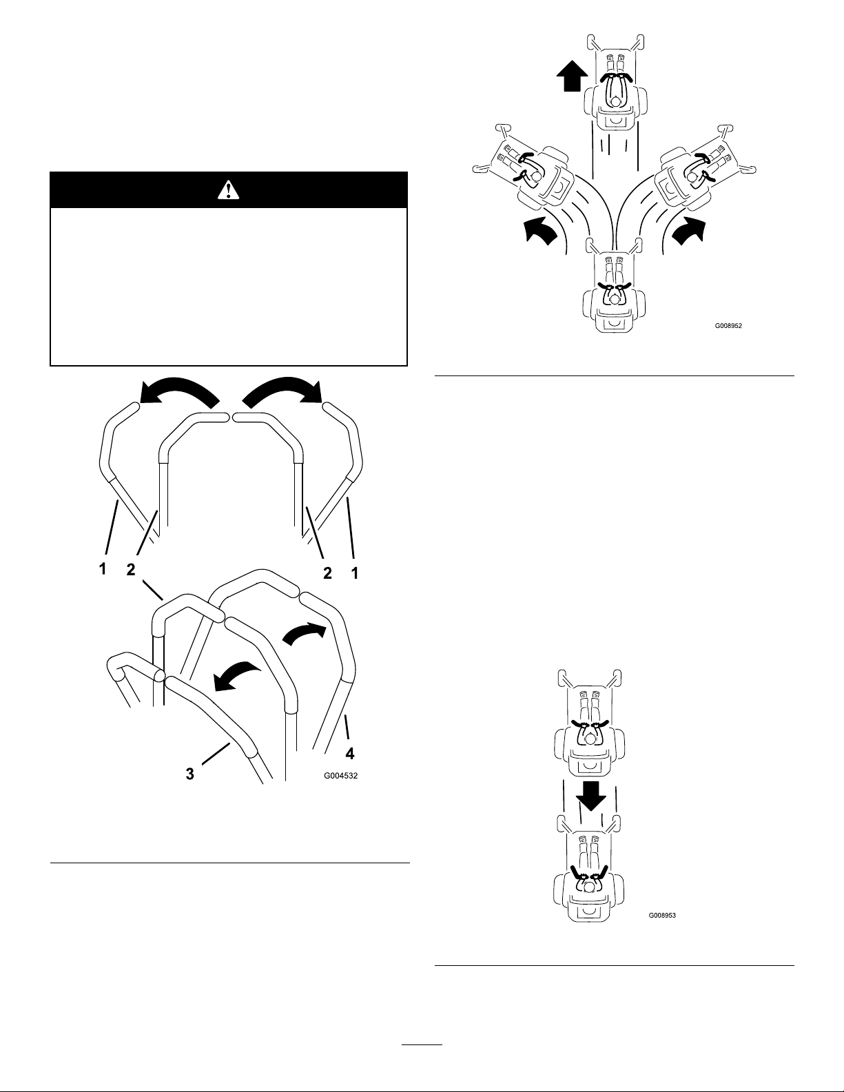
4.Movethebypassleversrearwardandthendown
tolocktheminplaceasshowninFigure21to
disengagethewheelmotors.Repeatthisoneach
sideofthemachine.
5.Movethemotioncontrolleversinwardtothe
neutralposition.
Themachineisnowabletobepushedbyhand.
Figure21
Rightsideshown
1.Bypassleverlocation
2.Leverpositionforpushing
themachine
3.Leverpositionfor
operatingthemachine
2.Loosenthelowerboltjustenoughtopivotthe
controlleverforeoraft(Figure20).Tightenboth
boltstosecurethecontrolinthenewposition.
3.Repeattheadjustmentfortheoppositecontrol
lever.
PushingtheMachinebyHand
Important:Alwayspushthemachinebyhand.
Nevertowthemachinebecausedamagemay
occur.
ToPushtheMachine
1.Parkthemachineonalevelsurfaceanddisengage
thebladecontrolswitch.
2.Movethemotioncontrolleversoutwardtopark
position,stoptheengine,removethekey,andwait
forallmovingpartstostopbeforeleavingthe
operatingposition.
3.Locatethebypassleversattherearofthemachine,
ontheleftandrightsideoftheframe.
ToOperatetheMachine
Movethebypassleversupwardandpushthemforward,
tothemiddleofthehorizontalslot(Figure21)to
engagethewheelmotors.
21
Page 22

GrassDeector
MowingDirection
Themowerhasahingedgrassdeectorthatdisperses
clippingstothesideanddowntowardtheturf.
Withoutthegrassdeector,dischargecover,
orcompletegrasscatcherassemblymounted
inplace,youandothersareexposedtoblade
contactandthrowndebris.Contactwith
rotatingmowerblade(s)andthrowndebriswill
causeinjuryordeath.
•Neverremovethegrassdeectorfrom
themowerbecausethegrassdeector
routesmaterialdowntowardtheturf.Ifthe
grassdeectoriseverdamaged,replaceit
immediately.
•Neverputyourhandsorfeetunderthe
mower.
•Nevertrytocleardischargeareaormower
bladesunlessyoumovethebladecontrol
switchtoOffandrotatetheignitionkeyto
Off.Alsoremovethekeyandpullthewire
offthesparkplug(s).
Alternatemowingdirectiontokeepthegrassstanding
straight.Thisalsohelpsdisperseclippingswhich
enhancesdecompositionandfertilization.
MowatCorrectIntervals
Normally,moweveryfourdays.Butremember,
grassgrowsatdifferentratesatdifferenttimes.So
tomaintainthesamecuttingheight,whichisagood
practice,mowmoreofteninearlyspring.Asthegrass
growthrateslowsinmidsummer,mowlessfrequently.
Ifyoucannotmowforanextendedperiod,rstmow
atahighcuttingheight;thenmowagaintwodayslater
atalowerheightsetting.
CuttingSpeed
Toimprovecutquality,useaslowergroundspeed.
AvoidCuttingTooLow
Ifthecuttingwidthofthemoweriswiderthanthe
moweryoupreviouslyused,raisethecuttingheightto
ensurethatuneventurfisnotcuttooshort.
LongGrass
OperatingTips
FastThrottleSetting
Forbestmowingandmaximumaircirculation,operate
theengineattheFastposition.Airisrequiredto
thoroughlycutgrassclippings,sodonotsetthe
height-of-cutsolowastototallysurroundthemower
byuncutgrass.Alwaystrytohaveonesideofthe
mowerfreefromuncutgrass,whichallowsairtobe
drawnintothemower.
CuttingaLawnfortheFirstTime
Cutgrassslightlylongerthannormaltoensurethatthe
cuttingheightofthemowerdoesnotscalpanyuneven
ground.However,thecuttingheightusedinthepastis
generallythebestonetouse.Whencuttinggrasslonger
thansixinchestall,youmaywanttocutthelawntwice
toensureanacceptablequalityofcut.
Cut1/3oftheGrassBlade
Ifthegrassiseverallowedtogrowslightlylongerthan
normal,orifitcontainsahighdegreeofmoisture,raise
thecuttingheighthigherthanusualandcutthegrassat
thissetting.Thencutthegrassagainusingthelower,
normalsetting.
WhenStopping
Ifthemachine’sforwardmotionmustbestoppedwhile
mowing,aclumpofgrassclippingsmaydropontoyour
lawn.T oavoidthis,moveontoapreviouslycutarea
withthebladesengaged.
KeeptheUndersideoftheMower
Clean
Cleanclippingsanddirtfromtheundersideofthe
moweraftereachuse.Ifgrassanddirtbuildupinside
themower,cuttingqualitywilleventuallybecome
unsatisfactory.
BladeMaintenance
Itisbesttocutonlyabout1/3ofthegrassblade.
Cuttingmorethanthatisnotrecommendedunless
grassissparse,oritislatefallwhengrassgrowsmore
slowly.
Maintainasharpbladethroughoutthecuttingseason
becauseasharpbladecutscleanlywithouttearingor
shreddingthegrassblades.Tearingandshreddingturns
grassbrownattheedges,whichslowsgrowthand
22
Page 23

increasesthechanceofdisease.Checkthecutterblades
dailyforsharpness,andforanywearordamage.File
downanynicksandsharpenthebladesasnecessary.If
abladeisdamagedorworn,replaceitimmediatelywith
agenuineTororeplacementblade.
23
Page 24

Maintenance
Note:Determinetheleftandrightsidesofthemachinefromthenormaloperatingposition.
RecommendedMaintenanceSchedule(s)
MaintenanceService
Interval
Beforeeachuseordaily
Every25hours
Every100hours
Every200hours
Every500hours
Beforestorage
MaintenanceProcedure
•Checkthesafetyinterlocksystem.
•Checktheaircleanerfordirty,looseordamagedparts.
•Checktheengineoillevel.
•Checkairintakeandcoolingareas,cleanasnecessary.
•Checkthecuttingblades.
•Inspectthegrassdeectorfordamage
•Cleanthemowerhousing.
•Greasealllubricationpoints.
•Servicethepaperelement.(moreoftenunderextremelydusty,dirtyconditions)
•Checktirepressure.
•Checkthebeltsforwear/cracks.
•Replacethepaperelement.(moreoftenunderextremelydusty,dirtyconditions)
•Changetheengineoilandlter.
•Cleantheblowerhousing(moreoftenunderextremelydusty,dirtyconditions).
•Replacethefuellter.
•Checksparkplugconditionandgap.
•Replacethesparkplug.
•Chargethebatteryanddisconnectbatterycables.
•Performallmaintenanceprocedureslistedabovebeforestorage.
•Paintanychippedsurfaces.
Important:Refertoyourengineoperator’smanualforadditionalmaintenanceprocedures.
Ifyouleavethekeyintheignitionswitch,someonecouldaccidentlystarttheengineandseriously
injureyouorotherbystanders.
Removethekeyfromtheignitionanddisconnectthewirefromthesparkplugbeforeyoudoany
maintenance.Setthewireasidesothatitdoesnotaccidentallycontactthesparkplug.
24
Page 25

Premaintenance
G005066
1
Lubrication
Procedures
GreasingtheBearings
RaisingtheSeat
Makesurethemotioncontrolleversarelockedinthe
parkposition.Lifttheseatforward.
Thefollowingcomponentscanbeaccessedbyraising
theseat:
•Serialplate
•Servicedecal
•Seatadjustmentknob
•Fuellter
•Fuses
•Batterycables
AccessingtheBattery
1.Raisetheseat.
2.RemovetheTORX
theleftcovertotheframeasshowninFigure22.
®
headfasteners(T25)securing
ServiceInterval:Every25hours—Greaseall
lubricationpoints.
GreaseType:No.2GeneralPurposeLithiumBase
Grease
1.Parkthemachineonalevelsurfaceanddisengage
thebladecontrolswitch.
2.Movethemotioncontrolleversoutwardtothe
parkposition,stoptheengine,removethekey,and
waitforallmovingpartstostopbeforeleavingthe
operatingposition.
3.Cleanthegreasettings(Figure23andFigure24)
witharag.Makesuretoscrapeanypaintoffofthe
frontofthetting(s).
Figure22
1.Leftcover
2.Torxheadfasteners(T25)
3.Battery
3.Lifttheplasticcoverawayfromthemachine.Retain
allfasteners.
Replacethecoverandsecureittotheframeusingthe
fastenersremovedpreviously.
1.Frontcastertire
1.Readtheinstructions
beforeservicingor
performingmaintenance.
2.Checktirepressureevery
25operatinghours.
25
Figure23
Figure24
Locatedontheseatpanunderside
3.Greaseevery25operating
hours.
4.Engine
Page 26
4.Connectagreaseguntoeachtting(Figure23and
G005300
1
2
3
4
1
2
3
4
Figure24).Pumpgreaseintothettingsuntilgrease
beginstooozeoutofthebearings.
5.Wipeupanyexcessgrease.
EngineMaintenance
ServicingtheAirCleaner
ServiceInterval:Beforeeachuseordaily—Checkthe
aircleanerfordirty,looseordamaged
parts.
Thisengineisequippedwithareplaceable,highdensity
paperaircleanerelement.Checktheaircleanerdailyor
beforestartingtheengine.Checkforabuildupofdirt
anddebrisaroundtheaircleanersystem.Keepthisarea
clean.Alsocheckforlooseordamagedcomponents.
Replaceallbentordamagedaircleanercomponents.
Note:Operatingtheenginewithlooseordamagedair
cleanercomponentscouldallowunlteredairintothe
enginecausingprematurewearandfailure.
Note:Servicetheaircleanermoreoftenunder
extremelydusty,dirtyconditions.
Figure25
1.Knobs,aircleanercover3.Paperelement
2.Aircleanercover4.Aircleanerbase
ServicingPaperElement
ServiceInterval:Every25hours—Servicethepaper
element.(moreoftenunderextremely
dusty,dirtyconditions)
Every100hours—Replacethepaper
element.(moreoftenunderextremely
dusty,dirtyconditions)
1.Removetheaircleanercover(Figure25).
2.Removetheaircleanerelementwiththeintegral
rubberseal(Figure25).
3.Gentlytapthepleatedsideofthepaperelementto
dislodgedirt.Donotwashthepaperelementor
usepressurizedair,asthiswilldamagetheelement.
26
Page 27

Replaceadirty,bent,ordamagedelement.Handle
G005176
2
3
1
2
F
L
G005068
1
2
3
newelementscarefully;donotuseiftherubberseal
isdamaged.
4.Cleanallaircleanercomponentsofanyaccumulated
dirtorforeignmaterial.Preventanydirtfrom
enteringthecarburetor.
5.Installtheaircleanerelementwiththepleatedside
“out”andseattherubbersealontotheedgesofthe
aircleanerbase(Figure25).
6.Reinstalltheaircleanercoverandsecurewiththe
twoknobs(Figure25).
ServicingtheEngineOil
OilType:Detergentoil(APIserviceSG,SH,SJ,or
higher)
CrankcaseCapacity:1.6qt(1.5l)whenthelteris
changed
Viscosity:Seethetablebelow .
Figure27
1.Oildipstick3.Oillevel
2.Fillertube
Figure26
CheckingtheOilLevel
ServiceInterval:Beforeeachuseordaily—Checkthe
engineoillevel.
1.Parkthemachineonalevelsurface,disengagethe
bladecontrolswitch,stoptheengine,andremove
thekey .
2.Makesuretheengineisstopped,level,andiscoolso
theoilhashadtimetodrainintothesump.
3.Tokeepdirt,grassclippings,etc.,outoftheengine,
cleantheareaaroundtheoilllcap/dipstickbefore
removingit.
4.Pullandremovetheoilllcap/dipstick;wipeoil
off.Reinsertthedipstickandpushrmlyintoplace
(Figure27).
5.Removethedipstickandchecktheoillevel.
(Figure27).
Theoillevelshouldbeupto,butnotover,theF
markonthedipstick.
6.Ifthelevelislow ,addoilofthepropertype,upto
theFmarkonthedipstick.Alwayscheckthelevel
withthedipstickbeforeaddingmoreoil.
Note:Topreventextensiveenginewearordamage,
alwaysmaintaintheproperoillevelinthecrankcase.
Neveroperatetheenginewiththeoillevelbelowthe
“L”markoroverthe“F”markonthedipstick.
ChangingtheOilandtheFilter
ServiceInterval:Every100hours—Changetheengine
oilandlter.
RellwithserviceclassSG,SH,SJorhigheroilas
speciedinthe“ViscosityGrades”table.
Changetheoilandlterwhiletheengineisstillwarm.
Theoilwillowmorefreelyandcarryawaymore
impurities.Makesuretheengineislevelwhenlling,
checking,orchangingtheoil.
Changetheoilandoillterasfollows:
1.Starttheengineandletitrununtilwarm.This
warmstheoilsoitdrainsbetter.
27
Page 28

2.Parkthemachinesothatthedrainsideisslightly
lowerthantheoppositesidetoassuretheoildrains
completely.
3.Disengagethebladecontrolswitchandmovethe
motioncontrolsoutwardtotheparkposition.
4.Stoptheengine,removethekey,andwaitforall
movingpartstostopbeforeleavingtheoperating
position.
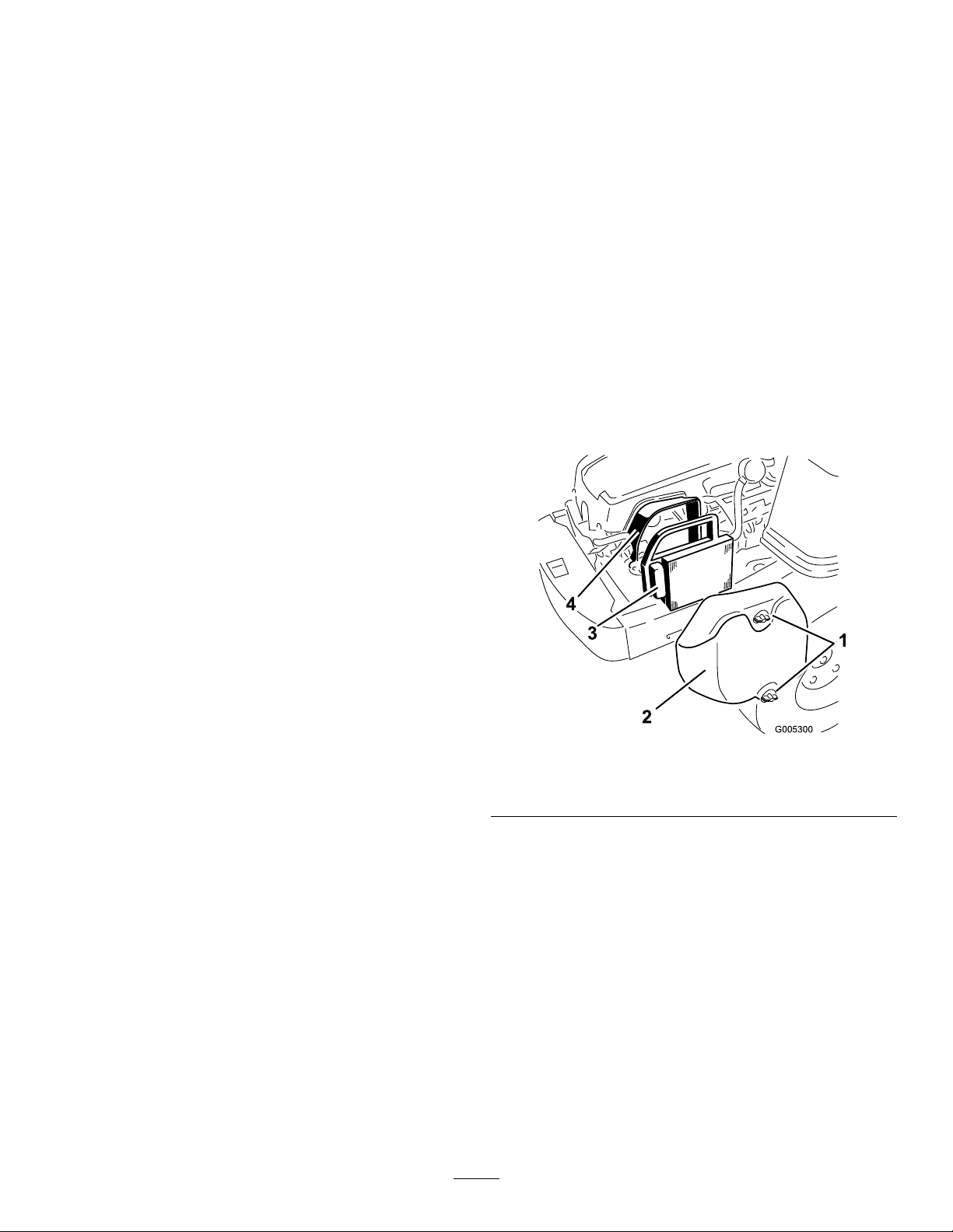
5.Cleantheareaaroundthedrainvalveandonthe
machineframe.Locatetheoildrainhoseandslide
itoverthedrainvalve(Figure28).
Figure29
1.Oildrainvalve
2.Machineframe5.Oillter
3.Oildrainhose
4.Pan
Figure28
1.Oildrainhose3.Holeinframe
2.Drainvalve
4.Oillter
6.Placetheoppositeendoftheoildrainhosethrough
thedrainholeintheframe(Figure28).
7.Placeapanunderneathmachinedirectlybelowthe
drainholeintheframeasshowninFigure29.
8.Turnthedrainvalve1/4counterclockwisetoopen
andallowtheoiltodrain(Figure29).Removethe
oilllcap/dipstick(Figure27).
9.Besuretoallowampletimeforcompletedrainage.
10.Removetheoldlterandwipeoffthemountingpad
(Figure29).
11.Whenoilhasdrainedcompletely,closetheoildrain
valve.Removetheoildrainhoseandwipeupany
excessoilontheframe(Figure29).
Note:Disposeoftheusedoilatarecyclingcenter.
12.Placethenewreplacementlterinashallowpan
withtheopenendup.Pournewoiloftheproper
type,inthroughthethreadedcenterhole.Stop
pouringwhentheoilreachesthebottomofthe
threads.Allowaminuteortwofortheoiltobe
absorbedbytheltermaterial.
13.Applyathinlmofcleanoiltotherubbergasketon
thenewlter.
14.Installthereplacementoilltertothemountingpad.
Turntheoillterclockwiseuntiltherubbergasket
contactsthepad,thentightenthelteranadditional
2/3to1turn(Figure30).
28
Page 29
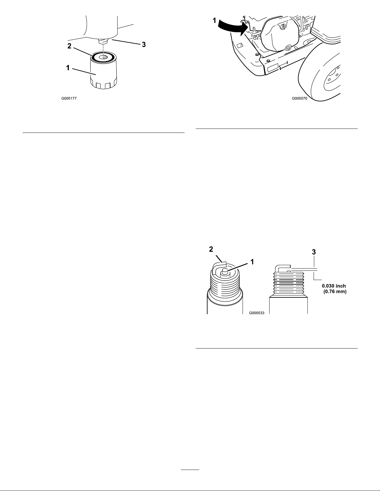
G005177
2
1
3
1.Oillter
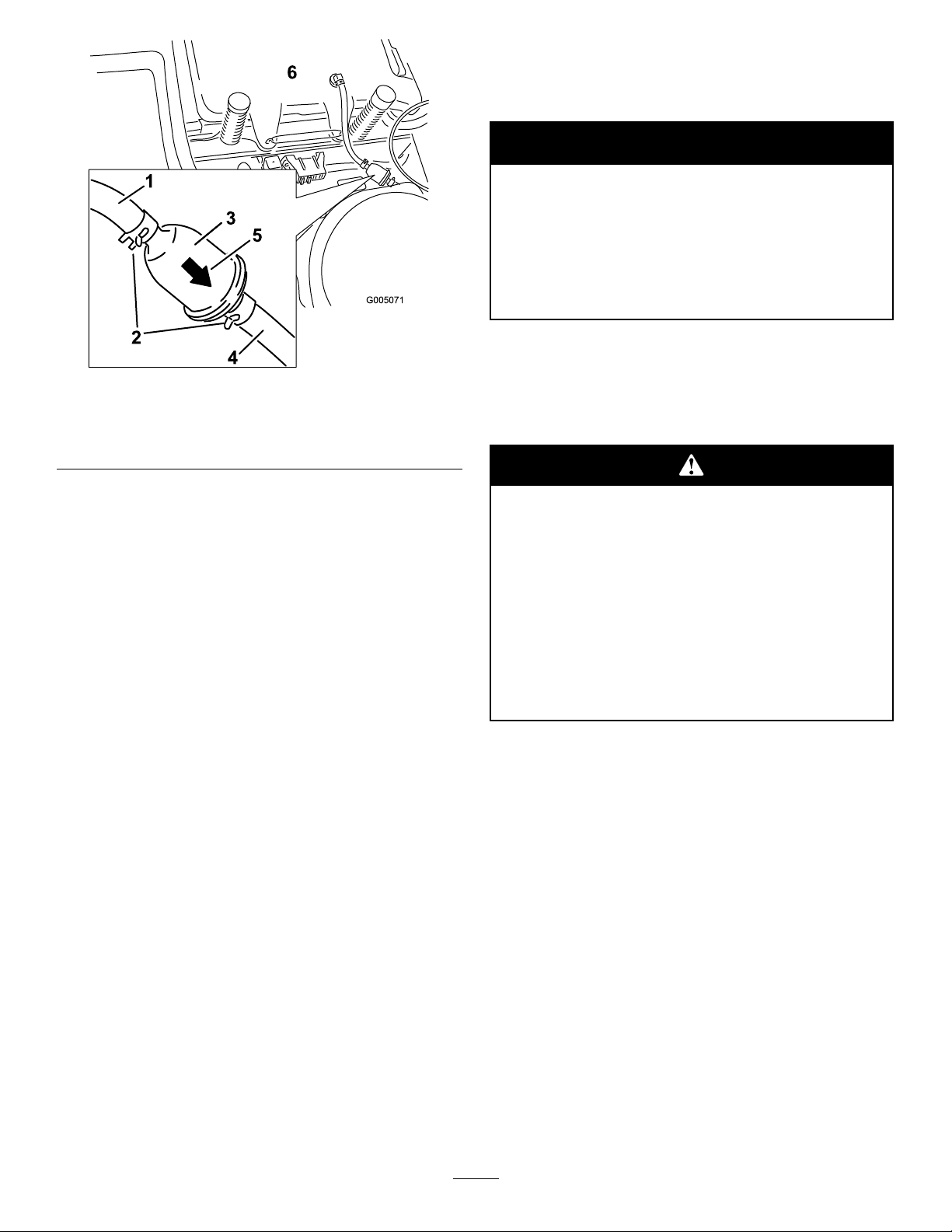
G005070
1
2.Gasket
Figure30
Figure31
3.Adapter
1.Sparkplugandwirelocation
15.Slowlypourapproximately80%ofthespeciedoil
CheckingtheSparkPlug
intothellertube(Figure27).
1.Lookatthecenterofthesparkplug(Figure32).
16.Installtheoilllcap/dipstickandpushrmlyinto
place(Figure27).
17.Checktheoillevel(Figure27);refertoChecking
theOilLevel.
18.Slowlyaddadditionaloiltobringittothefullmark.
19.Installtheoilllcap/dipstickandpushrmlyinto
place(Figure27).
Ifyouseelightbrownorgrayontheinsulator,the
engineisoperatingproperly .Ablackcoatingonthe
insulatorusuallymeanstheaircleanerisdirty.
Important:Nevercleanthesparkplug.Always
replacethesparkplugwhenithasablack
coating,wornelectrodes,anoilylm,orcracks.
2.Checkthegapbetweenthecenterandsideelectrodes
(Figure32).Bendthesideelectrode(Figure32)if
ServicingtheSparkPlug
thegapisnotcorrect.
ServiceInterval:Every200hours—Checksparkplug
conditionandgap.
Every500hours—Replacethespark
plug.
ThesparkplugisRFIcompliant.Equivalentalternate
brandplugscanalsobeused.Sparkplugreplacementis
recommendedat500hours.
Type:ChampionXC12YC(orequivalent)
AirGap:0.030inch(0.76mm)
1.Centerelectrodeinsulator3.Airgap(nottoscale)
2.Sideelectrode
Figure32
RemovingtheSparkPlug
1.Disengagethebladecontrolswitch,movethe
motioncontrolsoutwardtotheparkposition,stop
theengine,andremovethekey.
2.Pullthewireoffofthesparkplug(Figure31).Clean
aroundthesparkplugtopreventdirtfromfalling
intotheengineandpotentiallycausingdamage.
Note:Duetothedeeprecessaroundthespark
plug,blowingoutthecavitywithcompressedair
isusuallythemosteffectivemethodforcleaning.
Thesparkplugismostaccessiblewhentheblower
housingisremovedforcleaning.
3.Removethesparkplugandmetalwasher.
InstallingtheSparkPlug
1.Installthesparkplug.Makesurethattheairgapis
setcorrectly.
2.Tightenthesparkplugto30ft-lb(41N-m).
3.Pushthewireontothesparkplug(Figure31).
CleaningtheBlowerHousing
Toensurepropercooling,makesurethegrassscreen,
coolingns,andotherexternalsurfacesoftheengine
arekeptcleanatalltimes.
29
Page 30

Annuallyorevery100hoursofoperation(moreoften
underextremelydusty ,dirtyconditions),removethe
blowerhousingandanyothercoolingshrouds.Clean
thecoolingnsandexternalsurfacesasnecessary.Make
surethecoolingshroudsarereinstalled.Torquethe
blowerhousingscrewsto5.5ft-lb(7.5N-m).
FuelSystem
Maintenance
Important:Operatingtheenginewithablocked
grassscreen,dirtyorpluggedcoolingns,and/or
coolingshroudsremoved,willcauseenginedamage
duetooverheating.
Incertainconditions,gasolineisextremely
ammableandhighlyexplosive.Areor
explosionfromgasolinecanburnyouand
othersandcandamageproperty.
•Performanyfuelrelatedmaintenancewhen
theengineiscold.Dothisoutdoorsinan
openarea.Wipeupanygasolinethatspills.
•Neversmokewhendraininggasoline,and
stayawayfromanopenameorwherea
sparkmayignitethegasolinefumes.
ReplacingtheFuelFilter
ServiceInterval:Every100hours—Replacethefuel
lter.
Neverinstalladirtylterifitisremovedfromthefuel
line.
1.Parkthemachineonalevelsurfaceanddisengage
thebladecontrolswitch.
2.Movethemotioncontrolleversoutwardtothe
parkposition,stoptheengine,removethekey,and
waitforallmovingpartstostopbeforeleavingthe
operatingposition.
3.Raisetheseatandlocatethefuellinecomingfrom
thefueltankbelow .Thefuellterisinthefuelline
betweenthetankandengine.
30
Page 31
G005071
212
3
4
6
5
ElectricalSystem
Maintenance
Warning
CALIFORNIA
Proposition65Warning
Batteryposts,terminals,andrelated
accessoriescontainleadandleadcompounds,
chemicalsknowntotheStateofCalifornia
tocausecancerandreproductiveharm.
Washhandsafterhandling.
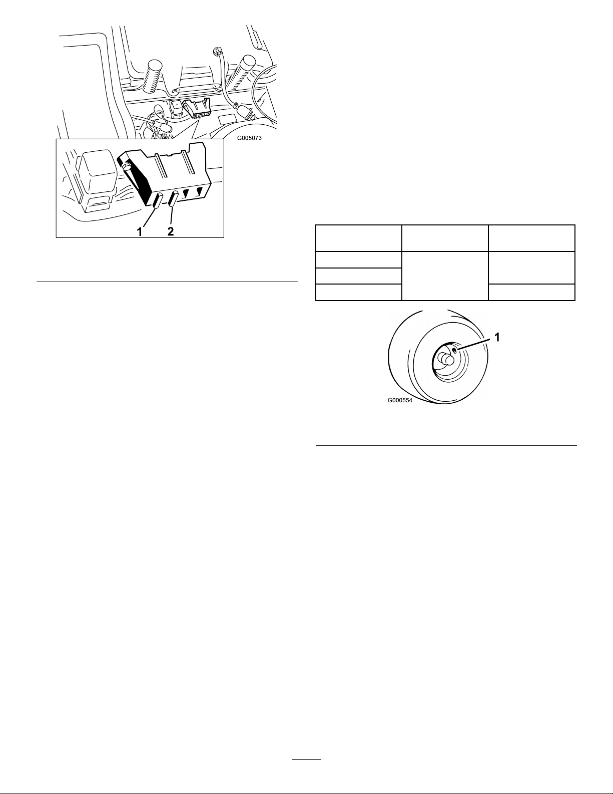
Figure33
1.Fuellinefromtank
2.Hoseclamp5.Flowdirectionarrow
3.Filter6.Fueltank
4.Squeezetheendsofthehoseclampstogetherand
slidethemawayfromthelter(Figure33).
5.Removethelterfromthefuellines.
6.Installanewlterwiththeowdirectionarrow
comingfromthefueltankandpointingtothe
engine.Movethehoseclampsclosetothelter
(Figure33)tosecureitinplace.
4.Fuellinetoengine
ChargingtheBattery
RemovingtheBattery
Batteryterminalsormetaltoolscouldshort
againstmetalmachinecomponentscausing
sparks.Sparkscancausethebatterygassesto
explode,resultinginpersonalinjury.
•Whenremovingorinstallingthebattery,do
notallowthebatteryterminalstotouchany
metalpartsofthemachine.
•Donotallowmetaltoolstoshortbetween
thebatteryterminalsandmetalpartsofthe
machine.
1.Parkthemachineonalevelsurfaceanddisengage
thebladecontrolswitch.
2.Movethemotioncontrolleversoutwardtothe
parkposition,stoptheengine,removethekey,and
waitforallmovingpartstostopbeforeleavingthe
operatingposition.
3.Removetheleftsideconsoletoaccessthebattery.
RefertheAccessingtheBatteryprocedureinthe
31
PremaintenanceProceduresforinstructions.
4.Disconnectthenegative(black)groundcablefrom
thebatterypost(Figure34).Retainallfasteners.
Page 32

Incorrectbatterycableroutingcoulddamage
G005072
1
2
3
4
5
6
7
themachineandcablescausingsparks.Sparks
cancausethebatterygassestoexplode,
resultinginpersonalinjury.
•Alwaysdisconnectthenegative(black)
batterycablebeforedisconnectingthe
positive(red)cable.
•Alwaysconnectthepositive(red)battery
cablebeforeconnectingthenegative(black)
cable.
5.Slidetherubbercoverupthepositive(red)cable.
Disconnectthepositive(red)cablefromthebattery
post(Figure34).Retainallfasteners.
6.Removethebatteryhold-down(Figure34)andlift
thebatteryfromthebatterytray.
Figure35
1.Positivebatterypost
2.Negativebatterypost
3.Red(+)chargerlead
4.Black(-)chargerlead
Note:Donotrunthemachinewiththebattery
disconnected,electricaldamagemayoccur.
InstallingtheBattery
1.Positionthebatteryinthetraywiththeterminal
poststowardtheoperatingposition(Figure34).
2.Installthepositive(red)batterycabletothepositive
(+)batteryterminalusingthefastenersremoved
previously.
Figure34
1.Battery5.Negativebatterypost
2.Positivebatterypost6.Wingnut,washer,andbolt
3.Bolt,washer ,andnut7.Batteryhold-down
4.Terminalboot
ChargingtheBattery
ServiceInterval:Beforestorage—Chargethebattery
anddisconnectbatterycables.
1.Removethebatteryfromthechassis;referto
RemovingtheBattery.
2.Chargethebatteryforaminimumof1hourat6to
10amps.Donotoverchargethebattery.
3.Whenthebatteryisfullycharged,unplugthecharger
fromtheelectricaloutlet,thendisconnectthe
chargerleadsfromthebatteryposts(Figure35).
3.Installthenegativebatterycabletothenegative
(-)batteryterminalusingthefastenersremoved
previously.
4.Slidetheredterminalbootontothepositive(red)
batterypost.
5.Securethebatterywiththehold-down(Figure34).
6.Installtheleftsideconsole.RefertotheAccessing
theBatteryprocedureinPremaintenanceProcedures
forinstructions.
ServicingtheFuses
Theelectricalsystemisprotectedbyfuses.Itrequires
nomaintenance;however,ifafuseblows,checkthe
component/circuitforamalfunctionorshort.
Fuse:
•MainF1-30amp,blade-type
•ChargeCircuitF2-25amp,blade-type
1.Raisetheseattogainaccesstothefuseholder
(Figure36).
2.Toreplaceafuse,pulloutonthefusetoremoveit
(Figure36).
32
Page 33
G005073
1
2
DriveSystem
Maintenance
CheckingtheTirePressure
ServiceInterval:Every25hours—Checktirepressure.
Maintaintheairpressureinthefrontandreartiresas
specied.Uneventirepressurecancauseunevencut.
Checkthepressureatthevalvestem(Figure37).Check
thetireswhentheyarecoldtogetthemostaccurate
pressurereading.
TirePressures
1.Main-30amp
Figure36
2.Chargecircuit-25amp
ModelRearTire
74360
74363
74370
1.Valvestem
13psi(90kPa)
FrontTire(caster
wheels)
35psi(241kPa)
20psi(138kPa)
Figure37
33
Page 34

MowerMaintenance
G009679
1
2
3
ServicingtheCuttingBlades
Maintainsharpbladesthroughoutthecuttingseason
becausesharpbladescutcleanlywithouttearingor
shreddingthegrassblades.Tearingandshreddingturns
grassbrownattheedges,whichslowsgrowthand
increasesthechanceofdisease.
Checkthecutterbladesdailyforsharpness,andforany
wearordamage.Filedownanynicksandsharpenthe
bladesasnecessary.Ifabladeisdamagedorworn,
replaceitimmediatelywithagenuineTororeplacement
blade.Forconvenientsharpeningandreplacement,you
maywanttokeepextrabladesonhand.
Awornordamagedbladecanbreak,anda
pieceofthebladecouldbethrownintothe
operator’sorbystander’sarea,resultingin
seriouspersonalinjuryordeath.
•Inspectthebladeperiodicallyforwearor
damage.
Figure38
1.Cuttingedge3.Wear/slotforming
2.Curvedarea
4.Damage
CheckingforBentBlades
Note:Themachinemustbeonalevelsurfaceforthe
followingprocedure.
1.Raisethemowerdecktothehighestheight-of-cut
position;alsoconsideredthe’transport’position.
2.Whilewearingthicklypaddedglovesorother
adequatehandprotectionslowlyrotatebladeto
bemeasureintoapositionthatallowseffective
measurementofthedistancebetweenthecutting
edgeandthelevelsurfacethemachineison.
•Replaceawornordamagedblade.
BeforeInspectingorServicingthe
Blades
Parkthemachineonalevelsurface,disengagetheblade
controlswitch,andmovethemotioncontrollevers
outwardtotheparkposition.Stoptheengineand
removethekey.
InspectingtheBlades
ServiceInterval:Beforeeachuseordaily—Checkthe
cuttingblades.
1.Inspectthecuttingedges(Figure38).Iftheedges
arenotsharporhavenicks,removeandsharpenthe
blades;refertoSharpeningtheBlades.
2.Inspecttheblades,especiallythecurvedarea
(Figure38).Ifyounoticeanydamage,wear,or
aslotforminginthisarea(item3inFigure38),
immediatelyinstallanewblade.
Figure39
1.Deck3.Blade
2.Spindlehousing
34
Page 35

3.Measurefromthetipofthebladetotheatsurface
G009680
1
2
3
G009681
1
2
3
G009680
1
2
3
here.
Figure40
1.Blade,inpositionformeasuring
2.Levelsurface
3.Measureddistancebetweenbladeandsurface(A)
Figure42
1.Opposingbladeedge,inpositionformeasuring
2.Levelsurface
3.Secondmeasureddistancebetweenbladeandsurface(B)
4.Rotatethesameblade180degreessothatthe
opposingcuttingedgeisnowinthesameposition.
Figure41
1.Blade,sidepreviouslymeasured
2.Measurementpositionusedpreviously
3.Opposingsideofbladebeingmovedintomeasurement
position
5.Measurefromthetipofthebladetotheatsurface
here.Thevarianceshouldbenomorethan1/8inch
(3mm).
Abladethatisbentordamagedcouldbreak
apartandcouldseriouslyinjureorkillyouor
bystanders.
•Alwaysreplacebentordamagedbladewith
anewblade.
•Neverleorcreatesharpnotchesinthe
edgesorsurfacesofblade.
A.IfthedifferencebetweenAandBisgreater
than1/8inch(3mm)replacethebladewitha
newblade.RefertoRemovingtheBladesand
InstallingtheBlades.
Note:Ifabentbladeisreplacedwithanewone
andthedimensionobtainedcontinuestoexceed
1/8inch(3mm),thebladespindlecouldbebent.
ContactanAuthorizedToroDealerforservice.
B.Ifthevarianceiswithinconstraints,movetothe
nextblade..
Repeatthisprocedureoneachblade.
RemovingtheBlades
Thebladesmustbereplacedifasolidobjectishit,
ifthebladeisoutofbalance,orthebladeisbent.
Toensureoptimumperformanceandcontinued
safetyconformanceofthemachine,usegenuineToro
replacementblades.Replacementbladesmadebyother
manufacturersmayresultinnon-conformancewith
safetystandards.
Holdthebladeendusingaragorthickly-paddedglove.
Removethebladebolt,curvedwasher,bladestiffener,
andbladefromthespindleshaft(Figure43).
35
Page 36
LevelingtheMowerDeck
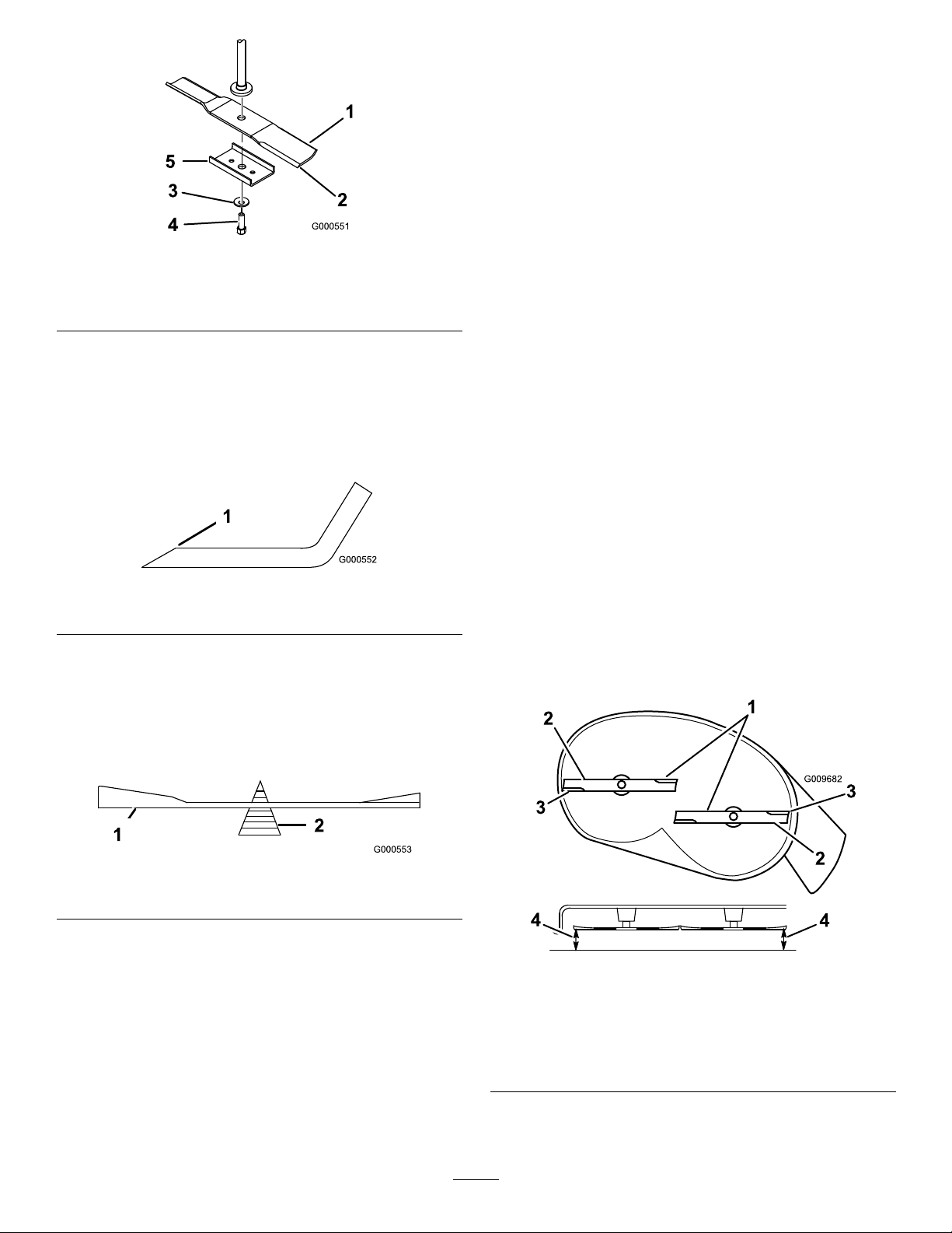
G009682
1
2
2
3
3
4
4
Checktoensurethemowerdeckislevelanytimeyou
installthemowerorwhenyouseeanunevencuton
yourlawn.
Themowerdeckmustbecheckedforbentblades
priortoleveling;anybentbladesmustberemoved
andreplaced.RefertotheCheckingforBentBlades
procedurebeforecontinuing.
Figure43
1.Sailareaofblade
2.Blade
3.Curvedwasher
4.Bladebolt
5.Bladestiffener
SharpeningtheBlades
1.Usealetosharpenthecuttingedgeatbothends
oftheblade(Figure44).Maintaintheoriginalangle.
Thebladeretainsitsbalanceifthesameamountof
materialisremovedfrombothcuttingedges.
Figure44
1.Sharpenatoriginalangle
2.Checkthebalanceofthebladebyputtingitona
bladebalancer(Figure45).Ifthebladestaysina
horizontalposition,thebladeisbalancedandcanbe
used.Ifthebladeisnotbalanced,lesomemetaloff
theendofthesailareaonly(Figure44).Repeatthis
procedureuntilthebladeisbalanced.
Themowerdeckmustbeleveledside-to-siderstthen
thefronttorearslopecanbeadjusted.
Requirements:
•Themachinemustbeonalevelsurface.
•Allfourtiremustbeproperlyinated.Referto
CheckingtheTirePressureintheDriveSystem
Maintenancesection.
Side-to-SideLeveling
1.Parkthemachineonalevelsurfaceanddisengage
thebladecontrolswitch.
2.Movethemotioncontrolleversoutwardtothe
parkposition,stoptheengine,removethekey,and
waitforallmovingpartstostopbeforeleavingthe
operatingposition.
3.Settheheight-of-cutlevertomiddleposition.
4.Carefullyrotatethebladessothattheyareallsideto
side(Figure46andFigure47).
Figure45
1.Blade2.Balancer
InstallingtheBlades
1.Installthebladeontothespindleshaft(Figure43).
Important:Thecurvedpartoftheblademust
bepointingupwardtowardtheinsideofthe
mowertoensurepropercutting.
1.Bladessidetoside
2.Sailareaofblade4.Measurefromthetipofthe
2.Installthebladestiffener,thecurvedwasher(cupped
MowerDeckswith2Blades
Figure46
3.Outsidecuttingedges
bladetotheatsurface
here
sidetowardtheblade)andthebladebolt(Figure43).
3.Torquethebladeboltto35-65ft-lb(47-88N-m).
36
Page 37

G005278
1
2
2
3
3
4
4
Figure47
3
G005074
1
2
3
4
5
6
MowerDeckswith3Blades
1.Bladessidetoside
2.Sailareaofblade4.Measurefromthetipofthe
3.Outsidecuttingedges
bladetotheatsurface
here
5.Measurebetweentheoutsidecuttingedgesand
theatsurface(Figure46andFigure47).Ifboth
measurementsarenotwithin3/16inch(5mm),an
adjustmentisrequired;continuewiththisprocedure.
6.Movetotheleftsideofthemachine.Loosen,but
donotremove,therearlockingnutonthehanger
bracket(Figure48).
7.Loosenthesidelockingnutonthehangerbracket
justenoughtoallowtheeccentricplatetobeadjusted
(Figure48).Usea3/8inchdriveextensionona
socketwrenchtomanipulatetheeccentricplate.Use
thewrenchtorepositiontheheightofthemower
deckandadjusttothedesiredheight.
8.Stopthedeckattheadjustedpositionandtightenthe
sidelockingnutonthehangerbrackettoholdthe
newposition(Figure48).Tightentherearlocking
nutonthehangerbracket.
Figure48
1.Hangerbracket4.Eccentricadjustmentplate
2.Rearlockingnut
3.Sidelockingnut6.Socketwrenchwith3/8
5.Socketwrenchhole
inchextension
AdjustingtheFront-to-RearBlade
Slope
Checkthefront-to-rearbladelevelanytimeyouinstall
themower.Ifthefrontofthemowerismorethan
5/16inch(7.9mm)lowerthantherearofthemower,
adjustthebladelevelusingthefollowinginstructions:
1.Parkthemachineonalevelsurfaceanddisengage
thebladecontrolswitch.
9.Continuelevelingthedeckbycheckingthe
front-to-rearbladeslope;refertoAdjustingthe
Front-to-RearBladeSlope.
2.Movethemotioncontrolleversoutwardtothe
parkposition,stoptheengine,removethekey,and
waitforallmovingpartstostopbeforeleavingthe
operatingposition.
3.Settheheight-of-cutlevertomiddleposition.
Note:Checkandadjusttheside-to-sideblade
levelifyouhavenotcheckedthesetting;referto
Side-to-SideLeveling.
4.Carefullyrotatethebladessotheyarefacingfrontto
rear(Figure49andFigure50).
37
Page 38

G009658
1
2
2
Figure49
G009659
1
2
3
2
3
MowerDeckswith2Blades
1.Bladesfronttorear
2.Measurefromthetipofthebladetotheatsurfacehere
Figure50
MowerDeckswith3Blades
1.Bladesfronttorear3.Measurefromthetipofthe
bladetotheatsurface
here
2.Outsidecuttingedges
5.Measurefromthetipofthefrontbladetotheat
surfaceandthetipoftherearbladetotheatsurface
(Figure49andFigure50).Ifthefrontbladetipis
not1/16-5/16inch(1.6-7.9mm)lowerthantherear
bladetip,adjustthefrontlocknut.
6.Toadjustthefront-to-rearbladeslope,rotatethe
adjustmentnutinthefrontofthemower(Figure51).
Figure51
1.Adjustingrod3.Locknut
2.Adjustingblock
7.Toraisethefrontofthemower,tightenthe
adjustmentnut.T olowerthefrontofthemower,
loosentheadjustmentnut.
8.Afteradjustment,checkthefront-to-rearslopeagain.
Continueadjustingthenutuntilthefrontbladetip
is1/16-5/16inch(1.6-7.9mm)lowerthantherear
bladetip(Figure49andFigure50).
9.Whenthefront-to-rearbladeslopeiscorrectcheck
theside-to-sidelevelofthemoweragain;referto
LevelingtheMowerfromSide-to-Side.
RemovingtheMower
1.Parkthemachineonalevelsurfaceanddisengage
thebladecontrolswitch.
2.Movethemotioncontrolleversoutwardtothe
parkposition,stoptheengine,removethekey,and
waitforallmovingpartstostopbeforeleavingthe
operatingposition.
3.Lowertheheight-of-cutlevertothelowestposition.
4.Removethehairpincotterandclevispinfromthe
frontsupportrod(Figure52).Carefullylowerthe
frontofthemowerdecktotheground.
38
Page 39

Figure52
2
2
3
G005077
1
2
2
3
1.Frontsupportrod3.Hairpincotterandclevis
pin
2.Lockingnut
5.Liftthemowerdeckandhangerbracketsclearof
therearliftrodandlowerthemowercarefullyto
theground(Figure53).
MowerBeltMaintenance
InspectingtheBelts
ServiceInterval:Every25hours—Checkthebeltsfor
wear/cracks.
Checkthebeltsforcracks,frayededges,burnmarks,or
anyotherdamage.Replacedamagedbelts.
ReplacingtheMowerBelt
Squealingwhenthebeltisrotating,bladesslippingwhen
cuttinggrass,frayedbeltedges,burnmarks,andcracks
aresignsofawornmowerbelt.Replacethemowerbelt
ifanyoftheseconditionsareevident.
1.Parkthemachineonalevelsurfaceanddisengage
thebladecontrolswitch.
2.Movethemotioncontrolleversoutwardtothe
parkposition,stoptheengine,removethekey,and
waitforallmovingpartstostopbeforeleavingthe
operatingposition.
3.Settheheight-of-cutatthelowestcuttingposition
[1-1/2inch(38mm)].
4.Removethebeltcoversovertheoutsidespindles.
5.Pulltheidlerpulleyinthedirectionshownin
Figure55androllthebeltoffofthepulleys.
Figure53
1.Mowerdeck
2.Hangerbracket
3.Rearliftrod
6.Slidethemowerdeckrearwardtoremovethemower
beltfromtheenginepulley .
7.Slidethemowerdeckoutfromunderneaththe
machine.
Note:Retainallpartsforfutureinstallation.
Thespringisundertensionwheninstalledand
cancausepersonalinjury.
Becarefulwhenremovingthebelt.
39
Page 40

G005078
1
2
3
3
4
5
1
2
3
3
4
5
G005191
1
2
3
3
4
5
waitforallmovingpartstostopbeforeleavingthe
operatingposition.
3.Slidethemowerunderthemachine.
4.Lowertheheight-of-cutlevertothelowestposition.
5.Lifttherearofthemowerdeckandguidethehanger
bracketsovertherearliftrod(Figure53).
6.Attachthefrontsupportrodtothemowerdeckwith
theclevispinandhairpincotter(Figure52).
7.Installthemowerbeltontotheenginepulley;refer
toReplacingtheMowerBelt.
Figure54
MowerDeckswith2Blades
1.Idlerpulley
2.Mowerbelt5.Enginepulley
3.Outsidepulley
MowerDeckswith3Blades
4.Spring
Figure55
ReplacingtheGrassDeector
ServiceInterval:Beforeeachuseordaily—Inspectthe
grassdeectorfordamage
Anuncovereddischargeopeningcouldallow
thelawnmowertothrowobjectsinthe
operator’sorbystander’sdirectionandresult
inseriousinjury.Also,contactwiththeblade
couldoccur.
Neveroperatethemachinewithoutgrass
deector,dischargecoverorgrasscollection
systeminplace.
Inspectthegrassdeectorfordamagebeforeeachuse.
Replaceanydamagedpartsbeforeuse.
1.LocateitemsshowninFigure56.
1.Idlerpulley
2.Mowerbelt5.Enginepulley
3.Outsidepulley
4.Spring
6.Routethenewbeltaroundtheenginepulleyand
mowerpulleys(Figure55).
7.Pulltheidlerpulleyinthedirectionshownin
Figure55androutethebeltontotheidlerpulley
(Figure55).
8.Installthebeltcoversovertheoutsidespindles.
InstallingtheMower
1.Parkthemachineonalevelsurfaceanddisengage
thebladecontrolswitch.
2.Movethemotioncontrolleversoutwardtothe
parkposition,stoptheengine,removethekey,and
40
Page 41

G005192
1
2
3
4
5
6
7
Figure56
1.Mowerdeck
2.Grassdeector6.Nut(3/8inch)
3.Grassdeectorbracket7.Shortstand-off
4.Rod
5.Spring
2.Removethenut(3/8inch)fromtherodunderthe
mower(Figure56).
3.Slidetherodoutoftheshortstand-off,spring,and
grassdeector(Figure56).Removethedamaged
orworngrassdeector.
Cleaning
WashingtheUndersideofthe
Mower
ServiceInterval:Beforeeachuseordaily—Cleanthe
mowerhousing.
Washtheundersideofthemoweraftereachuseto
preventgrassbuildupforimprovedmulchactionand
clippingdispersal.
1.Parkthemachineonalevelsurfaceanddisengage
thebladecontrolswitch.
2.Movethemotioncontrolleversoutwardtothe
parkposition,stoptheengine,removethekey,and
waitforallmovingpartstostopbeforeleavingthe
operatingposition.
3.Attachthehosecouplingtotheendofthemower
washouttting,andturnthewateronhigh
(Figure57).
Note:Spreadpetroleumjellyonthewashouttting
O-ringtomakethecouplingslideoneasierand
protecttheO-ring.
4.Replacethegrassdeector(Figure56).
5.Sliderod,straightend,throughthereargrass
deectorbracket.
6.Placethespringontherod,withendwiresdown,
andbetweenthegrassdeectorbrackets.Sliderod
throughsecondgrassdeectorbracket(Figure56).
7.Insertrodatfrontofgrassdeectorintoshort
stand-offondeck.Securerearendofrodintothe
mowerwithanut(3/8inch)(Figure56).
Important:Thegrassdeectormustbespring
loadedinthedownposition.Liftthedeector
uptotestthatitsnapstothefulldownposition.
Figure57
1.Washouttting3.O-ring
2.Hose
4.Coupling
4.Lowerthemowertothelowestheight-of-cut.
5.Sitontheseatandstarttheengine.Engagetheblade
controlswitchandletthemowerrunforoneto
threeminutes.
6.Disengagethebladecontrolswitch,stoptheengine,
andremovetheignitionkey.Waitforallmoving
partstostop.
7.Turnthewateroffandremovethecouplingfrom
thewashouttting.
41
Page 42

Note:Ifthemowerisnotcleanafteronewashing,
soakitandletitstandfor30minutes.Thenrepeat
theprocess.
8.Runthemoweragainforonetothreeminutesto
removeexcesswater.
Abrokenormissingwashoutttingcould
exposeyouandotherstothrownobjectsor
bladecontact.Contactwithbladeorthrown
debriscancauseinjuryordeath.
•Replacebrokenormissingwashouttting
immediately,beforeusingmoweragain.
•Neverputyourhandsorfeetunderthe
mowerorthroughopeningsinthemower.
Storage
CleaningandStorage
1.Disengagethebladecontrolswitch,movethe
motioncontrolsoutwardtotheparkposition,stop
theengine,andremovethekey.
2.Removegrassclippings,dirt,andgrimefromthe
externalpartsoftheentiremachine,especiallythe
engine.Cleandirtandchafffromtheoutsideofthe
enginecylinderheadnsandblowerhousing.
Important:Youcanwashthemachinewith
milddetergentandwater.Donotpressure
washthemachine.Avoidexcessiveuseof
water,especiallynearthecontrolpanel,engine,
hydraulicpumps,andmotors.
3.Servicetheaircleaner;refertoServicingtheAir
CleanerintheEngineMaintenancesection.
4.Greaseandoilthemachine;refertotheLubrication
section.
5.Changethecrankcaseoilandlter;refertoServicing
theEngineOilintheEngineMaintenancesection.
6.Checkthetirepressure;refertoCheckingtheTire
PressureintheDriveSystemMaintenancesection.
7.Chargethebattery;refertoServicingtheBattery
intheElectricalSystemMaintenancesection.
8.Checktheconditionoftheblades;refertoServicing
theCuttingBladesintheMowerMaintenance
section.
9.Preparethemachineforstoragewhennon-use
occursover30days.Preparethemachineforstorage
asfollows.
10.Addapetroleumbasedstabilizer/conditionertothe
fuelinthetank.Followthemixinginstructionsfrom
thestabilizermanufacturer.Donotuseanalcohol
basedstabilizer(ethanolormethanol).
Note:Afuelstabilizer/conditionerismosteffective
whenmixedwithfreshgasolineandusedatalltimes.
Runtheenginetodistributetheconditionedfuel
throughthefuelsystem(5minutes).
Stoptheengine,allowittocool,anddrainthefuel
tank;refertoDrainingtheFuelTankintheFuel
SystemMaintenancesection.
Restarttheengineandrunituntilitstops.
Choketheengine.Startandruntheengineuntilit
willnotstart.
Disposeoffuelproperly.Recyclepursuanttolocal
codes.
42
Page 43

Important:Donotstorestabilizer/conditioned
gasolineover30days.
11.Removethesparkplug(s)andcheckitscondition;
refertoServicingtheSparkPlugintheEngine
Maintenancesection.Withthesparkplug(s)
removedfromtheengine,pourtwotablespoonsof
engineoilintothesparkplughole.Usethestarter
tocranktheengineanddistributetheoilinsidethe
cylinder.Installthesparkplug(s).Donotinstallthe
wireonthesparkplug(s).
12.Cleananydirtandchafffromthetopofthemower.
13.Scrapeanyheavybuildupofgrassanddirtfromthe
undersideofthemower,thenwashthemowerwith
agardenhose.
14.Checktheconditionofthedriveandmowerbelts.
15.Checkandtightenallbolts,nuts,andscrews.Repair
orreplaceanypartthatiswornordamaged.
16.Paintallscratchedorbaremetalsurfaces.Paintis
availablefromyourAuthorizedServiceDealer.
17.Storethemachineinaclean,drygarageorstorage
area.Removethekeyfromtheignitionswitchand
keepitinamemorableplace.Coverthemachineto
protectitandkeepitclean.
43
Page 44

Troubleshooting
Problem
Theengineoverheats.
Thestarterdoesnotcrank
Theenginewillnotstart,startshard,or
failstokeeprunning.
PossibleCauseCorrectiveAction
1.Theengineloadisexcessive.1.Reducegroundspeed.
2.Theoillevelinthecrankcaseislow .2.Addoiltothecrankcase.
3.Thecoolingnsandairpassages
undertheengineblowerhousingare
plugged.
4.Theaircleanerisdirty .
5.Dirt,water,orstalefuelisinfuel
system.
1.Thebladecontrolswitchisengaged.1.Movethebladecontrolswitchto
2.Themotioncontrolleversarenotinthe
parkposition.
3.Theoperatorisnotseated.
4.Thebatteryisdead.
5.Theelectricalconnectionsarecorroded
orloose.
6.Afuseisblown.6.Replacethefuse.
7.Arelayorswitchisdamaged.
1.Thefueltankisempty .1.Fillthefueltank.
2.Thechokeisnoton.
3.Theaircleanerisdirty .
4.Thesparkplugwire(s)islooseor
disconnected.
5.Thesparkplug(s)ispitted,fouled,or
thegapisincorrect.
6.Thereisdirtinfuellter.6.Replacethefuellter.
7.Dirt,water,orstalefuelisinfuel
system.
8.Thereisincorrectfuelinthefueltank.8.Drainthetankandreplacethefuelwith
9.Theoillevelinthecrankcaseislow .9.Addoiltothecrankcase.
3.Removetheobstructionfromthe
coolingnsandairpassages.
4.Cleanorreplacetheaircleaner
element.
5.ContactanAuthorizedServiceDealer
Disengaged.
2.Movethemotioncontrolleversoutward
totheparkposition.
3.Sitontheseat.
4.Chargethebattery.
5.Checktheelectricalconnectionsfor
goodcontact.
7.ContactanAuthorizedServiceDealer.
2.MovethechokelevertoOn.
3.Cleanorreplacetheaircleaner
element.
4.Installthewire(s)onthesparkplug.
5.Installanew,correctlygappedspark
plug(s).
7.ContactanAuthorizedServiceDealer.
thepropertype.
Theenginelosespower.
Themachinedoesnotdrive.
1.Theengineloadisexcessive.1.Reducegroundspeed.
2.Theaircleanerisdirty .
3.Theoillevelinthecrankcaseislow .3.Addoiltothecrankcase.
4.Thecoolingnsandairpassages
undertheengineblowerhousingare
plugged.
5.Thesparkplug(s)ispitted,fouled,or
thegapisincorrect.
6.Theventinthefuelcapisclosed.6.Opentheventinthefuelcap.
7.Thereisdirtinthefuellter.7.Replacethefuellter .
8.Dirt,water,orstalefuelisinthefuel
system.
9.Thereisincorrectfuelinthefueltank.9.Drainthetankandreplacethefuelwith
1.Thebypassvalvesareopen
2.Thetractionbeltsareworn,loose,or
broken.
3.Thetractionbeltsareoffofthepulleys.3.ContactanAuthorizedServiceDealer.
4.Thetransmissionhasfailed.4.ContactanAuthorizedServiceDealer.
2.Cleantheaircleanerelement.
4.Removetheobstructionfromthe
coolingnsandairpassages.
5.Installanew,correctlygappedspark
plug(s).
8.ContactanAuthorizedServiceDealer.
thepropertype.
1.Closethetowvalves.
2.ContactanAuthorizedServiceDealer.
44
Page 45

Problem
PossibleCauseCorrectiveAction
Thereisabnormalvibration.
Unevencuttingheight.
Thebladesdonotrotate.
1.Theenginemountingboltsareloose.1.Tightentheenginemountingbolts.
2.Theenginepulley ,idlerpulley,orblade
pulleyisloose.
3.Theenginepulleyisdamaged.
4.Thecuttingblade(s)is/arebentor
unbalanced.
5.Ablademountingboltisloose.5.Tightentheblademountingbolt.
6.Abladespindleisbent.
1.Theblade(s)isnotsharp.1.Sharpentheblade(s).
2.Acuttingblade(s)is/arebent.2.Installanewcuttingblade(s).
3.Themowerisnotlevel.
4.Ananti-scalpwheelisnotsetcorrectly.4.Adjusttheanti-scalpwheelheight.
5.Theundersideofthemowerisdirty .5.Cleantheundersideofthemower.
6.Thetirepressureisincorrect.6.Adjustthetirepressure.
7.Abladespindleisbent.
1.Thedrivebeltisworn,looseorbroken.1.Installanewdrivebelt.
2.Thedrivebeltisoffofthepulley .
3.Themowerbeltisworn,loose,or
broken.
2.Tightentheappropriatepulley.
3.ContactanAuthorizedServiceDealer.
4.Installanewcuttingblade(s).
6.ContactanAuthorizedServiceDealer.
3.Levelthemowerfromside-to-sideand
front-to-rear.
7.ContactanAuthorizedServiceDealer.
2.Installthedrivebeltandcheckthe
adjustingshaftsandbeltguidesforthe
correctposition.
3.Installanewmowerbelt.
45
Page 46
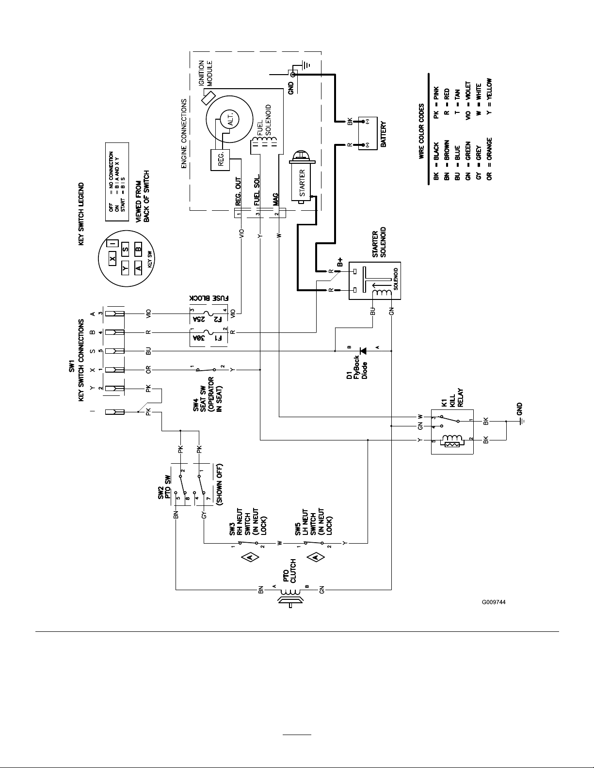
Schematics
G009744
ElectricalDiagram(Rev.A)
46
Page 47

Notes:
47
Page 48

TheT oroT otalCoverageGuarantee
AThree-Y earLimitedWarranty(LimitedWarrantyforCommercialUse)
TimeCutter
ZMowers
ConditionsandProductsCoveredunderTheToroTotal
CoverageGuarantee
TheT oro®Companyanditsafliate,T oroWarrantyCompany,pursuantto
anagreementbetweenthem,jointlypromisetorepairanyT oroProduct
usedforresidentialpurposes*,ifdefectiveinmaterialsorworkmanship
orifitstopsfunctioningduetothefailureofacomponentfortheperiod
listedbelow .
ThisWarrantyappliestoallTimeCutterZMowersandtheiraccessories.
Thiswarrantycoversthecostofpartsandlabor,butyoumustpay
transportationcosts.
Thefollowingtimeperiodsapplyfromthedateofpurchase:
ProductsWarrantyPeriod
TimeCutterZMowers
Attachments(foraboveunits)
Batteries1year
3years
3years
LimitedWarrantyforCommercialUse
Gas-poweredT oroProductsusedatmorethanonelocation,orusedfor
institutionalorrentaluse,arewarrantedfor30daysagainstdefectsin
materialsorworkmanship,90daysonengines.Componentsfailingdueto
normalweararenotcoveredbythiswarranty.
OwnerResponsibilities
YoumustmaintainyourToroProductbyfollowingthemaintenance
proceduresdescribedintheOperator’sManual.Suchroutine
maintenance,whetherperformedbyadealerorbyyou,isatyourexpense.
ItemsandConditionsNotCovered
Thereisnootherexpresswarrantyexceptforspecialemissionsystem
coverageandenginewarrantycoverageonsomeproducts.Thisexpress
warrantydoesnotcoverthefollowing:
•Costofregularmaintenanceserviceorparts,suchaslters,fuel,
lubricants,oilchanges,sparkplugs,airlters,bladesharpening/worn
bladeonmowers,cable/linkageadjustments,orbrakeandclutch
adjustments
•Anyproductorpartwhichhasbeenalteredormisusedandrequires
replacementorrepairduetoaccidentsorlackofpropermaintenance
•Repairsnecessaryduetoimproperbatterycare,failuretousefresh
fuel(lessthanonemonthold),orfailuretoproperlypreparetheunit
priortoanyperiodofnon-useoveronemonth
•Pickupanddeliverycharges
•Operationalmisuse,neglect,oraccidents
•RepairsorattemptedrepairsbyanyoneotherthananAuthorized
ToroServiceDealer
InstructionsforObtainingWarrantyService
IfyouthinkthatyourT oroProductcontainsadefectinmaterialsor
workmanship,followthisprocedure:
1.ContactanyAuthorizedT oroServiceDealertoarrangeserviceattheir
dealership.Tolocateadealerconvenienttoyou,refertotheYellow
Pagesofyourtelephonedirectory(lookunder“LawnMowers”)or
accessourwebsiteatwww.T oro.com.Y oumayalsocallthenumbers
listedinitem#3tousethe24-hourT oroDealerlocatorsystem.
2.Bringtheproductandyourproofofpurchase(salesreceipt)tothe
ServiceDealer.Thedealerwilldiagnosetheproblemanddetermine
ifitiscoveredunderwarranty.
3.IfforanyreasonyouaredissatisedwiththeServiceDealer’s
analysisorwiththeassistanceprovided,contactusat:
CustomerCareDepartment,ConsumerDivision
ToroWarrantyCompany
811 1LyndaleAvenueSouth
Bloomington,MN55420-1 196
Tollfreeat866-216-6029(U.S.customers)
Tollfreeat866-216-6030(Canadiancustomers)
GeneralConditions
Allrepairscoveredbythesewarrantiesmustbeperformedbyan
AuthorizedT oroServiceDealerusingT oroapprovedreplacementparts.
RepairbyanAuthorizedT oroServiceDealerisyoursoleremedyunder
thiswarranty.
NeitherTheToro®CompanynorT oroWarrantyCompanyisliablefor
indirect,incidental,orconsequentialdamagesinconnectionwiththe
useoftheToroProductscoveredbythesewarranties,includingany
costorexpenseofprovidingsubstituteequipmentorserviceduring
reasonableperiodsofmalfunctionornon-usependingcompletionof
repairsunderthesewarranties.
Somestatesdonotallowexclusionsofincidentalorconsequential
damages,sotheaboveexclusionsmaynotapplytoyou.
Thiswarrantygivesyouspeciclegalrights,andyoumayalsohaveother
rightswhichvaryfromstatetostate.
CountriesOtherthantheUnitedStatesorCanada
CustomerswhohavepurchasedT oroproductsexportedfromtheUnitedStatesorCanadashouldcontacttheirT oroDistributor(Dealer)toobtain
guaranteepoliciesforyourcountry,province,orstate.IfforanyreasonyouaredissatisedwithyourDistributor’sserviceorhavedifcultyobtaining
guaranteeinformation,contacttheT oroimporter.Ifallotherremediesfail,youmaycontactusatT oroW arrantyCompany .
*Residentialpurposesmeansuseoftheproductonthesamelotasyourhome.Useatmorethanonelocation,orinstitutionalorrentaluse,isconsidered
commercialuse,andthecommercialusewarrantywouldapply.
374-0257RevA
 Loading...