

Page 1
HGM-H™ Series Motor
Service and Repair Manual
BLN-0043
July 2011
Page 2

Page 3

TABLE OF CONTENTS
Foreword ............................... . . . .1
Description and Operation ................. . . . .2
Introduction ............................. . . . .2
General Description ......................... 2
External Features ........................ . . . .4
Technical Specifications ...................... 5
Product Identification ........................ 5
Safety .................................... 6
Personal Safety .......................... . . . .6
Tool Safety. . . . . . . . . . . . . . . . . . . . . . . . . . . . . . . . . .6
Work Area Safety ........................ . . . .6
Troubleshooting .......................... . . . .7
Work Area Safety ........................ . . . .8
Service and Maintenance .................. . . . .8
External Maintenance ..................... . . . .8
Service and Maintenance Procedures ........ . . . .8
Fluids .................................. . . . .8
Assembly After a Complete Teardown ........ . . .23
Drive Motor Exploded View ................. . . .24
Parts List . . . . . . . . . . . . . . . . . . . . . . . . . . . . . . . . . .25
Glossary of Terms . . . . . . . . . . . . . . . . . . . . . . . . 26-27
Notes . . . . . . . . . . . . . . . . . . . . . . . . . . . . . . . . . . 28-29
Fluid Volume and Level .................... . . . .8
Fluid Change Procedure ................... . . . .8
Purge Procedure ......................... . . . .9
Tear Down and Reassembly ................ . . .10
How to Use This Manual ................... . . .10
General Instructions ...................... . . .10
Tools .................................. . . . 11
Torques ................................ . . .11
Hydraulic Motor Removal .................. . . .12
Axle Hub Assembly ....................... . . .13
Brake Arm Assembly ...................... . . .14
Side Housing ............................ . . .15
Axle Shaft and Planetary Gear Set ........... . . .16
Bearing and Motor Block Cap ............... . . .17
Motor Block ............................. . . . 18
Motor Shaft and Brake Disc ................ . . . 19
Brake Shaft and Cam ..................... . . .20
Screw Tightening Sequence ................ . . .21
Sealant Path ............................ . . .21
Castle Nut Alternate Torque Method .......... . . .22
HGM-H i
Page 4

Page 5

FOREWORD
Headquartered in Sullivan, Illinois,
Hydro-Gear is a world leader in the design,
manufacture, and service of quality hydrostatic
transaxles for the lawn and garden industry.
The mission of our company is to be recognized by our customers and the industry as a
world-class supplier and the quality leader in
everything we do.
This Service and Repair Manual is designed
to provide information useful in servicing and
troubleshooting the Hydro-Gear® HGM-H™
series motor.
Also included is a glossary of terms that are
frequently used throughout the industry and in
Hydro-Gear service publications. Understanding terminology is very important!
It is necessary, and a good shop practice, that
your service area be equipped with the proper
tools and the mechanics be supplied the latest
information available. All repair procedures
illustrated in this guide are suggested, but preferred methods of repair.
Internal repair procedures require that the
HGM-H series motor be removed from the
vehicle.
This is not a certication, test or study guide for
a certication test. If a technician is interested
in certication, they should contact an agent
representing the EETC (Equipment and Engine
Training Council) at (262) 367-6700 or their
Hydro-Gear Central Service Distributor. Many
distributors will be hosting certication testing.
These study guides will cover most of the products and manufacturers in our industry.
For more information about Hydro-Gear or our
products, please contact your Central Service
Distributor, or call our Customer Service Department at (217) 728-2581.
HGM-H 1
Page 6

DESCRIPTION AND OPERATION
INTRODUCTION
The purpose of this manual is to provide information useful in servicing the Hydro-Gear®
HGM-H series motor. This manual includes
the HGM-H series motor general description,
hydraulic schematic, technical specications,
servicing and troubleshooting procedures.
Should servicing be required, the exterior of the
motor will need to be thoroughly cleaned before
beginning most procedures. Do not wash the
transaxle while it is hot. Do not use a pressure
washer to clean the unit.
GENERAL DESCRIPTION
The HGM-H series hydraulic motors are xed
displacement axial piston motors. The motor
is designed to convert hydraulic power into rotational power at the axle shaft. It operates at
an innitely variable speed range between zero
and maximum axle speed determined by motor
displacement and maximum pump ow in both
forward and reverse modes of operation.
movement out of the cylinder block, it gets
pushed back into the cylinder and uid inside
the piston is discharged through the low pressure port of the motor. Pistons develop torque
only through half of the cylinder block rotation
cycle. Therefore, multiple pistons are used to
provide a constant and continuous torque to
the motor shaft. Reversing the direction of the
incoming pressurized uid into the motor reverses the direction of the motor output rotation.
A hydraulic bypass is utilized in a hydraulic
system to permit moving the vehicle for a short
distance at a maximum of 2 m.p.h. (3.2 Km/h)
without starting the engine. The bypass will be
located on the hydraulic pump.
The HGM-H series motor utilizes a friction
type brake controlled by a cam attached to an
external actuating arm.
The HGM-H series motor is available with a
xed displacement of 15 cu. in. or 18 cu. in. (245
to 294 cc) maximum per revolution. The cylinder
block pistons in the HGM H series motors are
set at a xed displacement by a swash angle
that is integral to the motor housing. Therefore,
the motor is always at maximum displacement.
As pressurized uid from the pump pushes
against the cylinder block pistons, they forced
to rotate with the thrust bearing. As the pistons
rotate with the thrust bearing, they create torque
and rotory motion that is transmitted to the axle
shaft. Torque continues to develop as long as
the piston is being pushed out of the cylinder
block. When the piston reaches the end of the
2 HGM-H
Page 7

HGM-H 3
Page 8
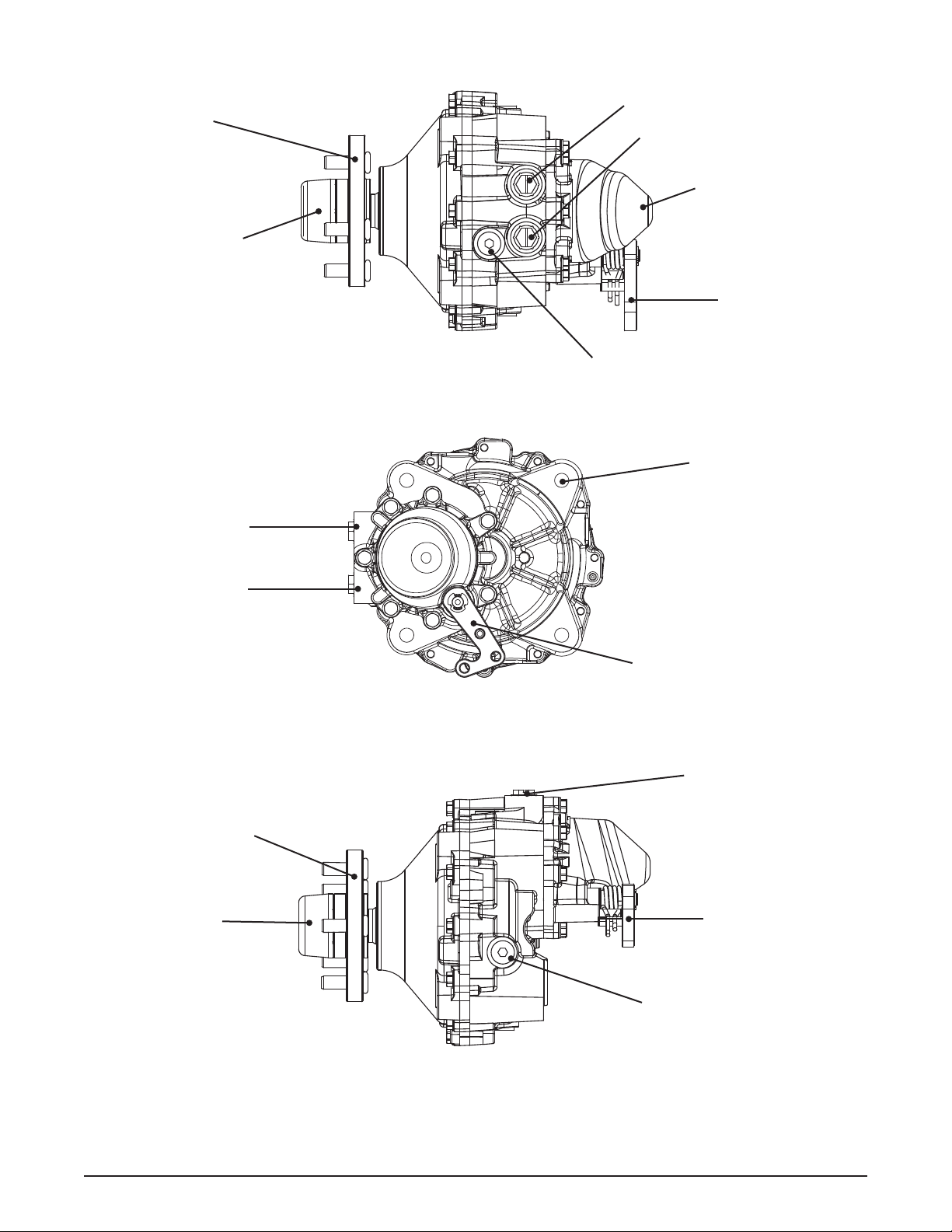
EXTERNAL FEATURES HGM-H SERIES MOTORS
WHEEL HUB
HUB NUT COVER
“B” PORT
“B” PORT
“A” PORT
HYDRAULIC HOUSING CAP
BRAKE ARM
FILL PORT / OPTIONAL CASE DRAIN
— Top View—
MOUNTING HOLE X 4
“A” PORT
WHEEL HUB
HUB NUT COVER
BRAKE ARM
— Back View—
“A” & “B” PORTS
BRAKE ARM
FILL PORT / OPTIONAL CASE DRAIN
— Side View—
Figure 1, External Features
4 HGM-H
Page 9
TECHNICAL SPECIFICATIONS
HGM-H™ Piston Mo to r tECHniCAL sPECiFiCAtions
Geometric Displacement
Maximum Speed
Continuous
Intermittent
Maximum Torque
Peak
Continuous
Intermittent
Maximum Oil Flow
Continuous
Intermittent
Axle Shaft Diameter
Axle Shaft End Options
Parking Brake Type
Max. weight applied to shaft/housing
Wheel Load Force - Radial
Weight of Unit
15 in3/rev (245.81 cc/rev) 18 in3/rev (294.97 cc/rev)
210 rpm
250 rpm
6600 in-lbf (75 N-m)
2700 in-lbf (30 N-m)
4900 in-lbf (75 N-m)
9.4 hp (7 KW)
20.5 hp (15.4 kW)
1.375 in (34.925 mm)
4 Bolt Flange
5 Bolt Flange
Internal Wet Disc
840 lbf (381 kg)
38.2 lb (17.3 kg)
185 rpm
210 rpm
7900 in-lbf (89 N-m)
3200 in-lbf (36 N-m)
5900 in-lbf (64 N-m)
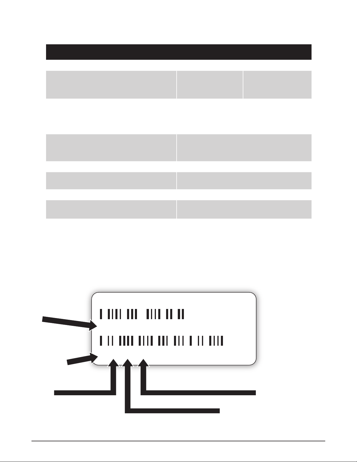
PRODUCT IDENTIFICATION
The model and conguration of the HGM-H can be determined from the label found on the
transaxle.
HYDRO-GEAR
Model Number
HGM-15H-XXCK
1 192 X 10428
Year Built
Date (Julian- Day of year)
Serial Number (unique for that model - for that day)
Type of Product and Build Information
Figure 2, Product Label
Assembled in USA
HGM-H 5
Page 10
SAFETY
This symbol points out important safety
instructions which, if not followed, could endanger the personal safety and/or property of yourself and others. Read and follow all instructions
in this manual before attempting maintenance
on your hydraulic motor. When you see this
symbol - HEED ITS WARNING.
Wear appropriate clothing. Loose or hanging
clothing or jewelry can be hazardous. Use the
appropriate safety equipment, such as eye
and hearing protection, and safety-toe and
slip-proof shoes.
Never use compressed air to clean debris from
yourself or your clothing.
TOOL SAFETY
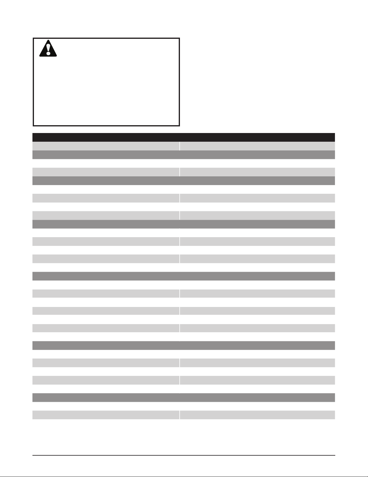
WARNING
POTENTIAL FOR SERIOUS INJURY
Inattention to proper safety, operation, or
maintenance procedures could result in
personal injury, or damage to the equipment. Before servicing or repairing the
hydraulic motor, fully read and understand the safety precautions described
in this section.
PERSONAL SAFETY
Certain safety precautions must be observed
while servicing or repairing the hydraulic motor.
This section addresses some of these precautions but must not be considered an all-inclusive
source on safety information. This section is
to be used in conjunction with all other safety
material which may apply, such as:
1. Other manuals pertaining to this machine,
2. Local and shop safety rules and codes,
3. Governmental safety laws and regulations.
Be sure that you know and understand the
equipment and the hazards associated with it.
Do not place speed above safety.
Use the proper tools and equipment for the
task.
Inspect each tool before use and replace any
tool that may be damaged or defective.
WORK AREA SAFETY
Keep the work area neat and orderly. Be sure
it is well lit, that extra tools are put away, trash
and refuse are in the proper containers, and dirt
or debris have been removed from the working
areas of the machine.
The oor should be clean and dry, and all extension cords or similar trip hazards should be
removed.
SERVICING SAFETY
Certain procedures may require the vehicle to
be disabled in order to prevent possible injury
to the servicing technician and/or bystanders.
The loss of hydrostatic drive line power may
result in the loss of hydrostatic braking capability.
Some cleaning solvents are ammable. Use
only approved cleaning materials: Do not use
explosive or ammable liquids to clean the
equipment.
Notify your supervisor whenever you feel there
is any hazard involving the equipment or the
performance of your job.
Never allow untrained or unauthorized personnel to service or repair the equipment.
6 HGM-H
To avoid possible re, do not use cleaning
solvents in an area where a source of ignition
may be present.
Discard used cleaning material in the appropriate containers.
Page 11
TROUBLESHOOTING
In many cases, problems with a hydraulic sys-
WARNING
Do not attempt any servicing or adjustments with the engine running.
Use extreme caution while inspecting
the drive belt assembly and all vehicle
linkage!
Follow all safety procedures outlined in
the vehicle owner’s manual.
TROUBLESHOOTING CHECKLIST
Possible Cause Corrective Action
Unit Operates In One Direction Only
Control linkage bent or out of adjustment Repair or replace linkage on vehicle pump assembly, Page 8
Drive belt slipping or pulley damaged Repair or replace belt/pulley on vehicle pump assembly, Page 8
Vehicle Does Not Drive/Track Straight
Vehicle tires improperly inated Refer to vehicle manufacturer suggested tire pressure
Control linkage bent or out of adjustment Repair or replace linkage on vehicle pump assembly, Page 8
Drive belt slipping or pulley damaged Repair or replace belt/pulley on vehicle pump assembly, Page 8
Brake Partially Engaged Disengage Brake, Replace damaged brake components, Page 14
Unit Is Noisy
Oil level low or contaminated oil Fill to proper level or change oil, Page 8
Excessive loading Reduce vehicle loading, Page 8
Loose parts Repair or replace loose parts
Air trapped in hydraulic system Purge hydraulic system, Page 9
Brake Partially Engaged Disengage Brake, Replace damaged brake components, Page 14
Unit Has No/Low Power
Engine speed low Adjust to correct setting
Control linkage bent or out of adjustment Repair or replace linkage on vehicle pump assembly, Page 8
Drive belt slipping or pulley damaged Repair or replace belt/pulley on vehicle pump assembly, Page 8
Oil level low or contaminated oil Fill reservoir to proper level or change oil, Page 8
Excessive loading Reduce vehicle loading, Page 8
Air trapped in hydraulic system Purge hydraulic system, Page 9
Brake Partially Engaged Disengage Brake, Replace damaged brake components, Page 14
Unit Is Operating Hot
Debris buildup around transaxle Clean off debris, Page 8
Oil level low or contaminated oil Fill to proper level or change oil, Page 8
Excessive loading Reduce vehicle loading, Page 8
Air trapped in hydraulic system Purge hydraulic system, Page 9
Brake Partially Engaged Disengage Brake, Replace broken, missing or frozen return spring
Transaxle Leaks Oil
Damaged seals, housing, or gaskets Replace damaged components
Air trapped in hydraulic system Purge hydraulic system, Page 9
tems are not related to a defective hydraulic
unit, but are caused by slipping drive belts,
partially engaged bypass valves, and loose or
damaged control linkages. Be sure to perform
all operational checks and adjustments outlined
in Service and Maintenance, before assuming
the hydraulic system is malfunctioning. The
table below provides a troubleshooting checklist to help determine the cause of operational
problems.
HGM-H 7
Page 12

SERVICE AND MAINTENANCE
EXTERNAL MAINTENANCE
Regular external maintenance of the hydraulic
motor should include the following:
1. Check the vehicle operator’s manual for the
recommended load ratings. Insure that the
current application does not exceed load
rating.
2. Check reservoir oil level in accordance with
the vehicle manufacturers recommendations.
3. Inspect the vehicle drive belt, idler pulley(s),
and idler spring(s). Insure that no belt slippage can occur. Slippage can cause low
input speed to the pump resulting in low
ow to the hydraulic motor.
4. Inspect the vehicle control linkage to the
directional control arm on the vehicles pump
assembly.
5. Inspect the hydraulic motors and pumps
for debris. Keeping the units debris free is
important in the overall performance of the
unit.
6. Inspect all external plumbing for possible
leaks or loose ttings. An air leak may be
difcult to detect on the “suction side” or inlet
line to the pump. Refer to Purging Procedure on page 9.
SERVICE AND MAINTENANCE
PROCEDURES
Some of the service procedures presented on
the following pages can be performed while the
transaxle is mounted on the vehicle. Any repair
procedures as mentioned in the repair section
of this manual must be performed after the unit
has been removed from the vehicle.
Cleanliness is a primary means of assuring
satisfactory life on repaired units. Thoroughly
clean all exposed surfaces prior to any type
of maintenance. Cleaning of all parts by using a solvent wash and air drying is usually
adequate. As with any precision equipment,
all parts must be kept free of foreign material
and chemicals.
Protect all exposed sealing surfaces and open
cavities from damage and foreign material. The
external surfaces should be cleaned before
beginning any repairs. Do not use a pressure
washer to clean the transaxle.
FLUIDS
The uids used in Hydro-Gear products have
been carefully selected, and only equivalent, or better products should be substituted
Typically, an engine oil with a minimum rating
of 9.0 cSt (55 SUS) at 230°F (110° C) and an
API classication of SL is recommended. Refer
to the vehicle manufacturer for recommended
oil.
FLUID VOLUME AND LEVEL
Certain situations may require additional uid
to be added or even replaced. In addition to
lling the hydraulic system with uid, an
additional 34 . oz. (1000mL) will need to be
added to the case via the highest ll point
of the HGM-H unit. Reference page 4 for
the proper ll location. Refer to the vehicle
manufacturer’s recommendations for the proper
ll location and level of the complete hydraulic
system. After maintenance or oil change, follow
purging procedures on page 9 and check the
uid level once the unit has been purged and
operated for 1 minute.
FLUID CHANGE
In the event of oil contamination or
degradation, oil addition or change may
alleviate certain performance problems. Refer
to the vehicle manufacturer’s recommended
oil change frequency. Refer to purging
procedures on page 9 after changing uids.
FILTERS
An inlet lter is required to insure that only clean
uid enter the system. Refer to the vehicle
manufacturer for approved lter replacement.
8 HGM-H
Page 13

SERVICE AND MAINTENANCE
PURGING PROCEDURE
The HGM-H motor can not be purged of air
as a stand alone component. The hydraulic
system as a whole will need to be purged after
any addition of oil to the system or a complete
oil change. This will most likely involve the use
of the hydraulic pumps bypass feature. If this
is not available, see the manufacturers recommendation for air purging.
Due to the effects air has on efciency in hydrostatic drive applications, it is critical that air
is removed or purged from the system.
These purge procedures must be preformed
anytime a hydrostatic system has been opened
for maintenance or repair, or if any additional
oil has been added to the system.
Air creates inefciency because it has compression and expansion rates that are higher than
that of oil.
Air trapped in the oil may cause the following
symptoms:
1. Noisy operation.
2. Lack of power or drive after short-term
operation.
3. High operation temperature and excessive
expansion of oil.
WARNING
POTENTIAL FOR SERIOUS INJURY
Certain procedures require the vehicle
engine to be operated and the vehicle to
be raised off of the ground. To prevent
possible injury to the servicing technician and/or bystanders, insure the vehicle is properly secured.
1. With the vehicles pump assembly bypass
valve open and the engine running, slowly
move the directional control in both forward
and reverse directions (10 to 20 times). As
air is purged from the unit, the oil level in
the reservoir may drop.
2. With the bypass valve closed and the engine
running, slowly move the directional control
in both forward and reverse directions (10
to 20 times). Check the oil level, and add
oil as required after stopping engine.
3. It may be necessary to repeat steps 1 and 2
until all the air is completely purged from the
system. When the hydraulic system moves
forward and reverse at normal speed and
the reservoir oil remains at a constant level,
purging is complete.
Before starting, make sure the reservoir is at
the proper oil level. If it is not, ll to the vehicle
manufacturer’s specications.
The following procedures should be performed
with the vehicle drive wheels off the ground,
then repeated under normal operating conditions.
HGM-H 9
Page 14

TEAR DOWN AND REASSEMBLY
HOW TO USE THIS MANUAL
Each subassembly illustrated in this manual is
illustrated with an exploded view showing the
parts involved. The item reference numbers
in each illustration are for assembly instructions only. See page 25 for part names and
descriptions. A complete exploded view and
item list of the transaxle is provided at the end
of the repair section.
GENERAL INSTRUCTIONS
Cleanliness is a primary means of assuring
satisfactory life on repaired units. Thoroughly
clean all exposed surfaces prior to any type
of maintenance. Cleaning of all parts by using a solvent wash and air drying is usually
adequate. As with any precision equipment,
all parts must be kept free of foreign material
and chemicals.
Protect all exposed sealing surfaces and open
cavities from damage and foreign material. The
external surfaces should be cleaned before
beginning any repairs. Do not use a pressure
washer to clean the transaxle.
Upon removal, it is recommended that all seals,
O-rings, and gaskets be replaced. During
installation lightly lubricate all seals, O-rings
and gaskets with a clean petroleum jelly prior
to assembly. Also protect the inner diameter of
seals during installation by covering the shaft
with a cellophane or plastic wrap material. Be
sure all remnants of this covering are removed
after servicing.
Parts requiring replacement must be replaced
from the appropriate kits identied in the Items
Listing, found at the end of this manual. Use
only original Hydro-Gear replacement parts
found at www.hydro-gear.com or at your HydroGear Central Service Distributor.
10 HGM-H
Page 15

TOOLS
REQUIRED TOOLS
Miscellaneous Sockets
Three Jaw Puller 1/2”-3/8” Adapter
Flat Blade Screw Driver (2) 3/8” Deep
Torque Wrench 1-1/8” Deep
Air Impact Wrench 1/4” Allen
Rubber or Neoprene Mallet 3/4” Deep
Breaker Bar
Side Cutters/Snips
Needle Nose Pliers
Large External Snap Ring Pliers
Small Internal Snap Ring Pliers
TORQUES
REQUIRED TORQUE VALUES
Item Description Torque Operation
4 Screw, Housing 280-340 in-lbs (31.6-38.4 Nm) All Housing Screws
10 Nut, Axle, Castlelated 275-350 ft-lbs (372.9-474.5 Nm) Hub
56 Nut, Brake 600-800 in-lbs (67.8-90.4 Nm) Brake Shaft
80 Plug 9/16-16 (Metal) 110-170 in-lbs (12.4-19.2 Nm) Oil Input Port
HGM-H 11
Page 16

MOTOR REMOVAL
NOTE: It is necessary to remove the HGM-H
Motor from the vehicle before performing the repair procedures presented in
this section.
Before starting any disassembly, make
certain that your work area is neat and
clean. Clean the external parts of the
transaxle.
The following procedures are pre-
sented in the order recommended for a
complete tear down of the transaxle.
Do not disassemble the unit any far-
ther than necessary to accomplish the
required repairs.
Reassembly is accomplished by per-
forming the “Assembly” portions of the
procedures. If the unit has been completely disassembled, a summary of
the assembly procedures, in the order
in which they should occur, is given on
page 23.
Figure 3, HGM-H Wheel Motor
12 HGM-H
Page 17

AXLE HUB ASSEMBLY
Refer to Figure 4
1. Remove the axle cap and discard (9).
2. Remove the cotter pin and discard (18).
3. Remove the castle nut (10).
4. Remove the taper hub assembly (11) and
discard.
NOTE: A new hub will have to be ordered
to replace the discarded hub.
5. Remove the axle shaft key (17).
Inspection
1. Check all components for excessive wear
or damage. Replace if necessary.
Assembly
1. Reassemble all parts in the reverse order
of disassembly.
2. When tightening the castle nut (10)*, refer to
the table on page 11 for the required torque
values.
NOTE: As a general rule, use the low end of the
torque specication . Once at the specied torque, rotate castle nut clockwise
to align with nearest cotter pin hole.
*SEE PAGE 22 FOR ALTERNATE
TORQUE METHOD.
11
10
9
17
18
Figure 4, Hub Assembly
HGM-H 13
Page 18

BRAKE ARM ASSEMBLY
Refer to Figure 5
Disassembly
1. Remove all items previously discussed in
their recommended order.
2. Mark the orientation of the brake arm (59)
before removal.
3. Remove the retaining ring (60).
4. Remove the brake handle (59), spring (82)
and spring pin (83).
5. Remove the spring spacer (81) and brake
spacer (57).
5. Remove the dowel pin (84) and the seal
(58). Discard the seal.
NOTE: Only remove the seal (58) and dowel
pin (84) if damaged or worn, or if doing
a complete disassembly.
Assembly
1. Reassemble all parts in the reverse order
of disassembly.
2. Install new seal (58) from seal kit.
Inspection
1. Inspect all parts for wear or damage. Replace as necessary.
57
81
82
84
58
60
83
59
Figure 5, Brake Arm Assembly
14 HGM-H
Page 19
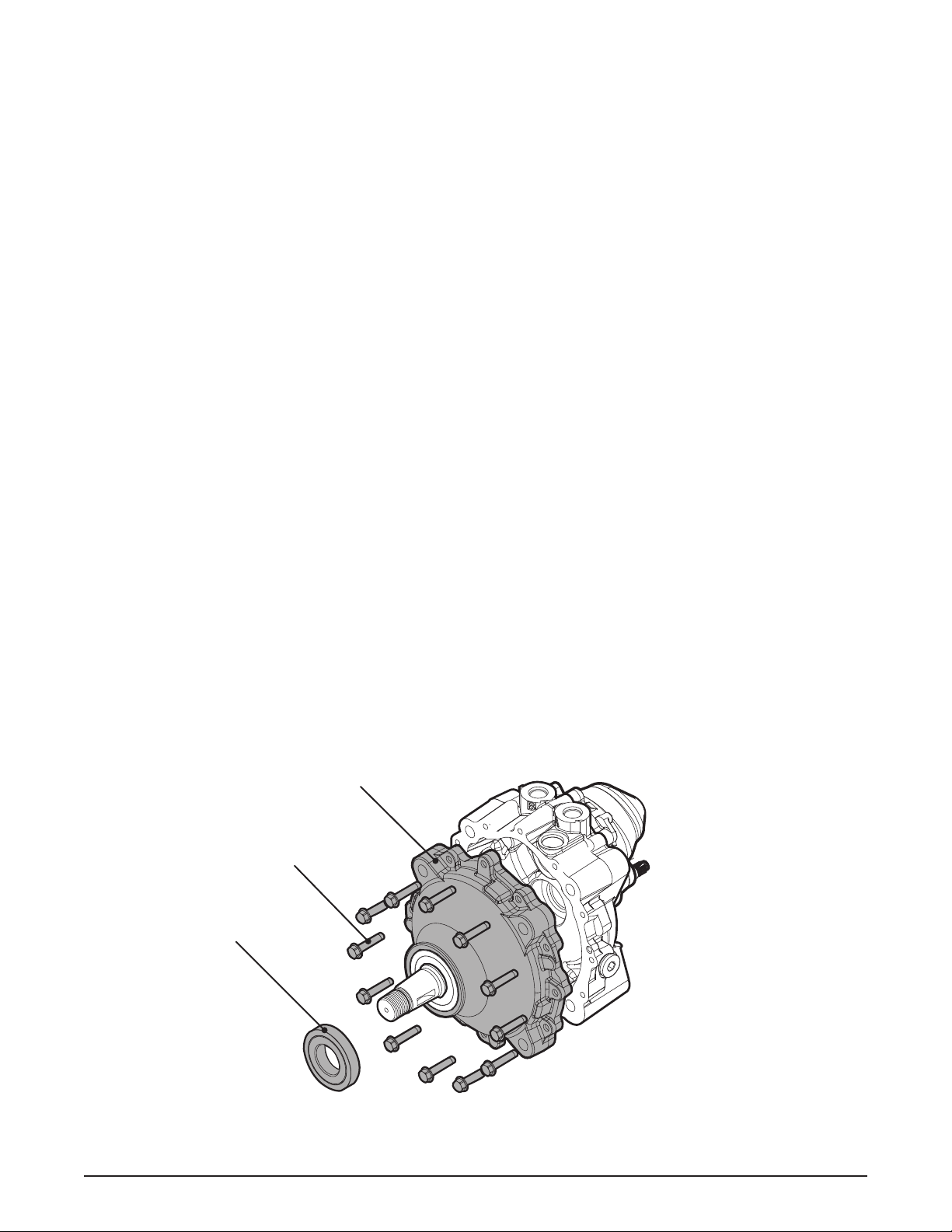
SIDE HOUSING
Refer to Figure 6
Disassembly
1. Remove all external items previously discussed in their recommended order.
2. Remove the seal (13) and discard.
3. Remove the twelve housing screws (4),
then separate axle housing (1) from middle
housing (2).
Inspection
1. Inspect the bearing and bushing areas in the
side cover for excessive wear or damage.
Replace if necessary.
Assembly
1. Reassemble all parts in the reverse order
of disassembly.
2. Apply a bead of sealant around the perimeter of the middle housing face. See “Sealant Application Diagram” on page 21.
NOTE: Remove all old sealant from the axle
housing (1) and the middle housing (2)
before applying new sealant.
3. Align the side housing (2) with the main
housing (1). Use care not to smear the sealant bead.
4. Install the twelve housing screws (6). Refer to the screw tightening pattern on page
21.
5. When tightening the fasteners, refer to the
table on page 11 for the required torque
values.
13
6. Install a new axle seal (13) from the seal
kit.
1
4 (X 12)
Figure 6, Side Housing
HGM-H 15
Page 20

AXLE SHAFT AND PLANETARY GEAR SET
Refer to Figures 7 and 8
Disassembly
1. Remove all external items previously discussed in their recommended order.
NOTE: Note the location of the ring gear
tabs.
2. Remove the axle bearing (14) and washer
(15).
3. Remove the ring gear (21).
4. Remove the axle shaft (16) and planetary
assembly from the middle housing (2).
5. Remove the axle retaining ring (26), axle
shaft spacer (25), axle gear (24), planet
gears (22), sun gear (23) and the carrier
(20).
NOTE: The sun gear (23) and axle gear (24) are
pressed as one piece in some models.
(Figure 8a)
Assembly
1. Reassemble all parts in the reverse order
of disassembly.
2
Ring Gear Tabs
Ring Gear
Axle Shaft (16)
Planetary Assembly
Figure 7, Planetary Gear Set
NOTE: When installing the ring gear assembly
— line up the ring gear tabs with the
housing tabs.
Inspection
1. Inspect all items of the planetary gear set
for wear and or damage.
21
20
16
14
15
25
26
24
23
22 (X 3)
23 & 24
Figure 8a
Figure 8, Planetary Gear Set
16 HGM-H
Page 21

BEARING AND MOTOR BLOCK CAP
Refer to Figure 9
Disassembly
1. Remove all external items previously discussed in their recommended order.
2. Remove the seven housing cap screws (4)
and the housing cap (3).
3. Remove the o-ring (6) and discard.
4. Remove the thrust bearing (45), retaining
ring (47) and washer (46). Discard the retaining ring (47)
Inspection
1. Inspect the races of the thrust bearing (80)
for wear or damage.
Assembly
1. Reassemble all parts in the reverse order
of disassembly.
2. Install new o-ring (6) and retaining ring (47)
from seal kit.
3. Place the thrust bearing assembly (45) so
the thick race contacts the motor block pistons.
4. Install the seven housing screws (6). Refer
to the screw tightening pattern on page
21.
5. When tightening the fasteners, refer to the
table on page 11 for the required torque
values.
47
46
Motor Block Pistons
6
45
Figure 9, Motor Block Cap and Bearing
HGM-H 17
4 (X 7)
3
Page 22

MOTOR BLOCK
Refer to Figure 10
Disassembly
1. Remove all external items previously discussed in their recommended order.
2. Remove the motor block assembly (40) from
the middle housing (2).
3. Disassemble the motor block assembly and
inspect all parts.
Inspection
1. Inspect the pistons (43), piston seats
(42), springs (41) and the motor cylinder
block (40) of the motor block assembly for
scratches and or wear. Replace the motor
block assembly if necessary.
Assembly
1. Reassemble all parts in the reverse order
of disassembly.
2. Apply a light coating of oil to all running surfaces to prevent scoring during reassembly.
42
40
2
Figure 10, Motor Block
41
43
18 HGM-H
Page 23
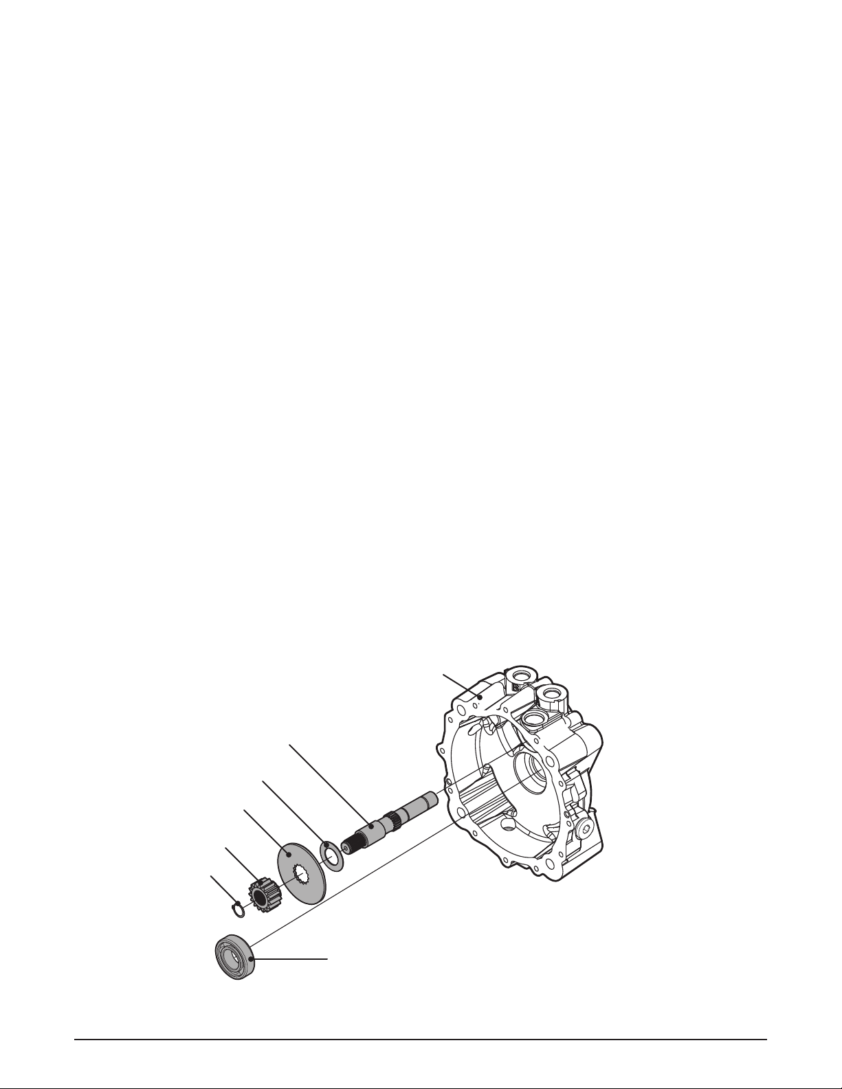
MOTOR SHAFT AND AXLE BEARING
Refer to Figure 11
Disassembly
1. Remove all external items previously discussed in their recommended order.
2. Remove the motor shaft (34), retaining ring
(30) and gear (31) out of the middle housing
(2).
3. Remove the brake rotor (32) and the washer
(33).
4. Remove the inboard axle bearing (27).
Inspection
1. Inspect for scratches and or damage to the
brake rotor (32).
3. Inspect the gear (31) and motor shaft (34)
for wear or damage.
Assembly
1. Reassemble all parts in the reverse order
of disassembly.
2
34
33
32
31
30
27
Figure 11, Motor Shaft and Brake Disc
HGM-H 19
Page 24

BRAKE SHAFT AND CAM
Refer to Figure 12
Disassembly
1. Remove all external items previously discussed in their recommended order.
NOTE: If the brake is working properly and the
brake components are not damaged,
there is no need to remove the brake
assembly.
2. Remove the brake shaft nut (56) and washer
(55).
3. Remove the brake shaft (50), the splined
cam (51), the puck cam (52) and brake puck
(54).
4. Remove the magnet screw (7) magnet (8)
and dowel pin (53).
NOTE: Only remove the dowel pin (53) and
magnet components (7, 8) if damage
is present.
Inspection
1. Inspect the puck (54) for excessive wear.
2. Inspect all components for wear or damage.
Assembly
1. Reassemble all parts in the reverse order
of disassembly.
2. When tightening the nut (56), refer to the
table on page 11 for the required torque
values.
56
52
51
50
20 HGM-H
54
8
53
7
Figure 12, Brake Shaft Assembly
55
Page 25

SCREW TIGHTENING SEQUENCE
1
3
5
7
9
11
2
Figure 13, Side Housing Bolt Sequence
7
12
4
10
1
8
6
6
4
5
2
3
Figure 14, Motor Housing Cap Bolt Sequence
SEALANT PATH
Figure 15, Sealant Path
HGM-H 21
Page 26

CASTLE NUT (10) ALTERNATE TORQUE METHOD
NOTE: The ideal method for installing a new hub and nut is utilizing a torque wrench capable
of 275 ft-lbs. If a 275 ft-lbs torque wrench is not available please use the alternative
procedure outlined in this document. All parts need to be clean and free of lubrication.
Tools:
1. Air Compressor and Air Impact
Wrench or Electric Impact Wrench
(REMOVAL ONLY)
2. 1 7/16” Socket
3. Socket Extension
4. Torque Wrench (Must be capable of
achieving 50 ft-lbs)
5. Paint Pen or visible marker.
6. Flash Light
Procedure:
1. Engage machine parking brake.
2. Remove nut cover.
3. Remove existing nut.
4. Install new nut to 50 ft-lbs
5. Mark a point on the new nut and hub
per Figure 16. (Point A)
6. Measure 2 nut ats or 120º per Figure
16 and mark hub. (Point B)
7. Turn nut clockwise until mark “A” lines
up with mark “B”. (Figure 17)
8. Continue turning nut clockwise until
the slot lines up with the cross hold of
the axle shaft.
9. Install cotter pin.
Placement mark
A
Figure 16
10. Reinstall nut cover.
A
B
Figure 17
Figure 16 / Figure 17, Alternate Torque Method
B
Placement mark
22 HGM-H
Page 27

ASSEMBLY AFTER A COMPLETE TEARDOWN
If the unit has been torn down completely, the
following summary identies the assembly procedures necessary to completely assemble the
unit. Each assembly procedure is located by a
page reference.
The part reference numbers provided in each
assembly procedure are keyed to the individual
exploded views, and are also keyed to the complete unit exploded view on page 24.
1. Install the brake shaft (50) and cam assembly (51, 52) to the middle housing (2).
Page 20
2. Install the inboard axle bearing (27).
Page 19
3. Install the motor shaft (34), washer (33),
brake rotor (32), motor shaft gear (31), retaining ring (30). Page 19
4. Install the block assembly (40) onto the motor shaft (34). Page 18
8. Apply sealant material onto housing middle
housing (2). Page 21
9. Install the axle housing (1), the 12 housing
screws (4), and the axle seal (13).
Page 15
10. Install brake dowel pin (84), brake seal (58),
brake spacer (57), and spring spacer (81).
Page 14
11. Install the brake arm spring (82), the spring
pin (83), the brake arm (59), and the retaining ring (60). Page 14
12. Install the axle key (17), hub assembly (11),
axle nut (10), cotter pin (18) and axle cap
(9). Page 13
13. Install the unit into the machine and ll the
case with 34 . oz. of uid after lling the
hydraulic system. Page 8
5. Install the retaining ring (46) and washer
(47) onto the motor shaft (34). Page 17
6. Install the thrust bearing (45), o-ring (6),
housing cap (3) and housing cap screws
(7). Page 17
7. Install the three planet gears (22) onto the
carrier (20) and then onto the axle shaft
(16). Install the sun gear (23) onto the axle
shaft (16). Install the bull gear (24), thrust
spacer (25) and retaining ring (26) onto the
axle shaft and set assembly aside. Place
the axle assembly into the main housing.
Install the ring gear (21) onto the axle shaft
so that the teeth mesh with the planet gears
and install the washer (15) and axle bearing
(14) onto the axle shaft (16). Page 16
Note: Make sure that two of the tabs on the
outer diameter of the ring gear (21)
locate between the tabs cast into the
main housing.
- Some models will have the sun gear
(23) and the bull gear (24) as one
pressed gear.
HGM-H 23
Page 28

HGM-H MOTOR EXPLODED VIEW
24 HGM-H
Page 29

HGM-H MOTOR PARTS LIST
1 Housing, Axle
2 Housing, Middle
3 Housing, Motor Block
4 Screw, Housing
6 O-ring, Motor Housing
9 Cap, Axle
10 Nut, Axle
11 Hub, Taper (1.25, 4 Bolt / 1.25, 5 Bolt)
13 Seal, Axle
14 Bearing, Axle, Outboard
15 Spacer, Axle
16 Axle
17 Key, Woodruff, Axle
18 Pin, Cotter 5/32 X 2
20 Carrier
21 Gear, Ring
22 Gear, Planet
23 Gear, Sun
24 Gear, Internal, 71T
25 Spacer, Axle, Gear
26 Retaining Ring
27 Bearing, Axle, Inboard
30 Retaining Ring, Motor Shaft
31 Gear, 19T
32 Rotor, Brake
33 Washer, Motor Shaft
34 Shaft, Motor
40 Motor Block Kit, 16cc Cylinder
45 Thrust Bearing
46 Washer
47 Retaining Ring, External
50 Shaft, Brake
51 Splined Cam, Brake
52 Cam Puck, Brake
53 Pin, Ground, Dowel
54 Brake Puck
55 Washer, Flat .63 X 1.0 X.125
56 Nut, Brake
57 Spacer, Brake
58 Seal, Brake
59 Handle, Brake Actuating
60 Retaining Ring, Brake Handle
71 Plug, 3/4 SAE, Plastic
80 Plug, 3/4-16, Metal
81 Spacer, Spring
82 Spring, Torsion
83 Pin, Spring 5/16 X 1.375
84 Pin, Hardened Ground Dowel 5/16 X1.5
HGM-H 25
Page 30

GLOSSARY OF TERMS
Axial Piston: Type of design for hydraulic motors and pumps in which the pistons are arranged
parallel with the spindle (input or output shaft).
Bypass Valve: A valve whose primary function is to open a path for the uid to bypass the motor
or pump. Also referred to occasionally as the freewheel valve or dump valve.
Case Drain Line (Return Line): A line returning uid from the component housing to the reser-
voir.
Cavitation: A concentrated gaseous condition within the uid causing the rapid implosion of a
gaseous bubble.
Center Section: A device which acts as the valve body and manifold of the transmission.
Charge Pump: A device which supplies replenishing uid to the uid power system (closed
loop).
Charge Pressure: The pressure at which replenishing uid is forced into a uid power system.
Charge Relief Valve: A pressure control valve whose primary function is to limit pressure in the
charge circuit.
Check Valve: A valve whose primary function is to restrict ow in one direction.
Closed Loop: A sealed and uninterrupted circulating path for uid ow from the pump to the
motor and back.
Decay Rate: The ratio of pressure decay over time.
End Cap: See “Center Section.”
Entrained Air: A mechanically generated mixture of air bubbles having a tendency to separate
from the liquid phase.
Gerotor: A formed rotor set operating about an eccentric that provides a xed displacement for
pumps or motors.
Hydraulic Motor: A device which converts hydraulic uid power into mechanical force and motion by transfer of ow under pressure.
Hydraulic Pump: A device which converts mechanical force and motion into hydraulic uid power
by producing ow.
Hydrostatic Pump: See “Hydraulic Pump.”
Hydrostatic Transaxle: A multi component assembly including a gear case and a hydrostati-
transmission.
Hydrostatic Transmission: The combination of a hydraulic pump and motor in one housing to
form a device for the control and transfer of power.
Inlet Line: A supply line to the pump.
26 HGM-H
Page 31

Integrated Zero-Turn Transaxle: The combination of a hydrostatic transmission and gear case
in one housing to form a complete transaxle.
Manifold: A conductor which provides multiple connection ports.
Neutral: Typically described as a condition in which uid ow and system pressure is below that
which is required to turn the output shaft of the motor.
Pressure Decay: A falling pressure.
Priming: The lling of the charge circuit and closed loop of the uid power system during start
up, frequently achieved by pressurizing the uid in the inlet line.
Purging: The act of replacing air with uid in a uid power system by forcing uid into all of the
components and allowing the air a path of escape.
Rated Flow: The maximum ow that the power supply system is capable of maintaining at a
specic operating pressure.
Scoring: Scratches in the direction of motion of mechanical parts caused by abrasive contaminants.
Swash Plate: A mechanical device used to control the displacement of the pump pistons in a
uid power system.
System Charge Check Valve: A valve controlling the replenishing ow of uid from a charge
circuit to the closed loop in a uid power system.
System Pressure: The pressure which overcomes the total resistance in a system, including all
efciency losses.
Valve: A device which controls uid ow direction, pressure, or ow rate.
Variable Displacement Pump: A pump in which the displacement per revolution can be var-
ied.
Volumetric Displacement: The volume for one revolution.
HGM-H 27
Page 32

NOTES
28 HGM-H
Page 33

NOTES
HGM-H 29
Page 34

Page 35

Page 36

© 2011 HYDRO-GEAR
Printed in U.S.A.
Rev. P
 Loading...