

Page 1
FormNo.3389-840RevB
ZMaster
®
8000SeriesRiding
Mower
with42inor48inDirect-CollectCuttingUnit
ModelNo.74310—SerialNo.315000001andUp
ModelNo.74311—SerialNo.315000001andUp
ModelNo.74312—SerialNo.315000001andUp
Registeratwww.T oro.com.
OriginalInstructions(EN)
*3389-840*B
Page 2
WARNING
CALIFORNIA
Proposition65Warning
Thisproductcontainsachemicalorchemicals
knowntotheStateofCaliforniatocausecancer,
birthdefects,orreproductiveharm.
Theengineexhaustfromthisproduct
containschemicalsknowntotheStateof
Californiatocausecancer,birthdefects,
orotherreproductiveharm.
ThissparkignitionsystemcomplieswithCanadianICES-002.
Becauseinsomeareastherearelocal,state,orfederal
regulationsrequiringthatasparkarresterbeusedonthe
engineofthismachine,asparkarresterisavailableas
anoption.Ifyourequireasparkarrester,contactyour
AuthorizedToroServiceDealer.
GenuineT orosparkarrestersareapprovedbytheUSDA
ForestryService.
Important:ItisaviolationofCaliforniaPublic
ResourceCodeSection4442touseoroperatetheengine
onanyforest-covered,brush-covered,orgrass-covered
landwithoutasparkarrestermufermaintainedin
workingorder,ortheengineconstricted,equipped,and
maintainedforthepreventionofre.Otherstatesor
federalareasmayhavesimilarlaws.
Theenclosedengineowner’smanualissuppliedfor
informationregardingtheUSEnvironmentalProtection
Agency(EPA)andtheCaliforniaEmissionControl
Regulationofemissionsystems,maintenance,and
warranty.Replacementsmaybeorderedthroughtheengine
manufacturer.
CustomerServiceandhavethemodelandserialnumbersof
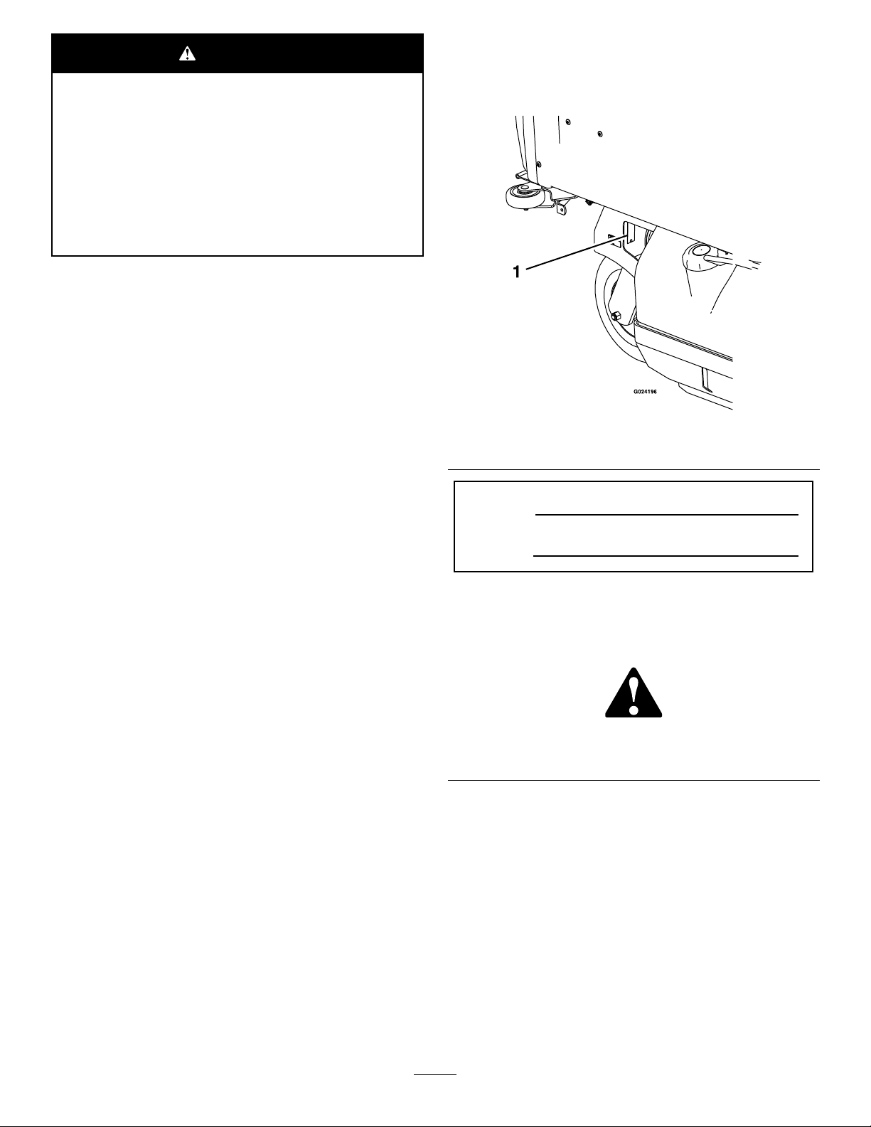
yourproductready.Figure1identiesthelocationofthe
modelandserialnumbersontheproduct.Writethenumbers
inthespaceprovided.
Figure1
1.Modelandserialnumberlocation
ModelNo.
SerialNo.
Thismanualidentiespotentialhazardsandhassafety
messagesidentiedbythesafety-alertsymbol(Figure2),
whichsignalsahazardthatmaycauseseriousinjuryordeath
ifyoudonotfollowtherecommendedprecautions.
Introduction
Thisrotary-blade,ridinglawnmowerisintendedtobeused
byresidentialhomeownersorprofessional,hiredoperators.
Itisdesignedprimarilyforcuttinggrassonwell-maintained
lawnsonresidentialorcommercialproperties.Itisnot
designedforcuttingbrushorforagriculturaluses.
Readthisinformationcarefullytolearnhowtooperateand
maintainyourproductproperlyandtoavoidinjuryand
productdamage.Youareresponsibleforoperatingthe
productproperlyandsafely.
YoumaycontactTorodirectlyatwww .T oro.comforproduct
andaccessoryinformation,helpndingadealer,ortoregister
yourproduct.
Wheneveryouneedservice,genuineT oroparts,oradditional
information,contactanAuthorizedServiceDealerorToro
©2016—TheToro®Company
8111LyndaleAvenueSouth
Bloomington,MN55420
Figure2
1.Safety-alertsymbol
Thismanualuses2wordstohighlightinformation.
Importantcallsattentiontospecialmechanicalinformation
andNoteemphasizesgeneralinformationworthyofspecial
attention.
Contactusatwww.Toro.com.
2
PrintedintheUSA
AllRightsReserved
Page 3

Contents
Safety...........................................................................4
SafeOperatingPractices...........................................4
SlopeIndicator.......................................................6
SafetyandInstructionalDecals.................................7
ProductOverview.........................................................14
Controls...............................................................14
Specications........................................................15
Operation....................................................................16
AddingFuel...........................................................16
CheckingtheEngine-OilLevel.................................17
BreakinginaNewMachine......................................17
ThinkSafetyFirst...................................................17
OperatingtheParkingBrake....................................18
OperatingtheThrottle............................................18
OperatingtheIgnitionSwitch..................................18
UsingtheFuel-ShutoffValve...................................19
OperatingthePTO-EngagementLever.....................19
StartingandStoppingtheEngine..............................19
TheSafetyInterlockSystem.....................................21
DrivingForwardorBackward..................................21
StoppingtheMachine.............................................22
RaisingtheMowerDeckintoServicePosition.............22
LoweringtheMowerDecktotheOperating
Position.............................................................23
AdjustingtheFillReductionSystem(FRS)
Bafes...............................................................23
AdjustingtheHeightofCut.....................................24
EmptyingtheHopper.............................................24
ClearingtheHopperScreen.....................................24
UsingtheDrive-Wheel-ReleaseValves.......................25
TransportingtheMachine........................................25
LoadingtheMachine..............................................26
OperatingTips......................................................27
Maintenance.................................................................28
RecommendedMaintenanceSchedule(s)......................28
Lubrication...............................................................29
LubricatingtheMachine..........................................29
EngineMaintenance..................................................32
ServicingtheAirCleaner.........................................32
ServicingtheEngineOil..........................................33
ServicingtheSparkPlugs.........................................35
CheckingtheSparkArrester(ifequipped)..................35
FuelSystemMaintenance...........................................36
ServicingtheElectronicFuelInjection
System..............................................................36
ReplacingtheFuelFilter..........................................36
ServicingtheFuelTank...........................................36
ElectricalSystemMaintenance....................................37
ServicingtheBattery...............................................37
ServicingtheFuses.................................................38
AdjustingtheSafetySwitches...................................38
JumpStartingtheMachine.......................................38
DriveSystemMaintenance.........................................40
AdjustingtheTracking............................................40
CheckingtheTirePressure......................................40
CheckingtheWheelLugNuts..................................40
CheckingtheWheelHubNuts.................................40
AdjustingtheCasterPivotBearings...........................40
CoolingSystemMaintenance......................................41
CleaningtheEngineScreenandEngine-Oil
Cooler...............................................................41
ServicingtheEngine-OilCooler...............................41
CleaningtheEngineCoolingFinsand
Shrouds.............................................................41
CheckandCleantheHydraulicPumps.......................42
BrakeMaintenance....................................................42
AdjustingtheParkingBrake.....................................42
BeltMaintenance......................................................44
InspectingtheBelts................................................44
ReplacingthePTOBelts.........................................44
ReplacingthePumpDriveBelt.................................44
AdjustingtheBeltGuides........................................45
ControlsSystemMaintenance.....................................45
AdjustingtheReverse-StopRod...............................45
AdjustingtheSpeed-ControlLeverTension...............46
AdjustingtheSpeed-ControlLinkage........................46
AligningthePTO-DrivePulley.................................47
AligningthePump-DrivePulley...............................47
AdjustingthePTOBrakeSpring...............................48
AdjustingtheHopperDoor.....................................48
AdjustingtheLocking-PinStopontheMower
Deck.................................................................48
HydraulicSystemMaintenance....................................49
ServicingtheHydraulicSystem.................................49
MowerDeckMaintenance...........................................50
LevelingtheMowerDeck........................................50
ServicingtheCuttingBlades.....................................51
RemovingtheMowerDeck.....................................53
InstallingtheMowerDeck.......................................54
AdjustingtheLocking-PinStopontheMower
Deck.................................................................55
Cleaning...................................................................55
CleaningundertheMower.......................................55
CleaningDebrisfromtheMachine............................55
DisposingofWaste.................................................55
Storage........................................................................56
CleaningandStorage..............................................56
Troubleshooting...........................................................57
Schematics...................................................................59
3
Page 4

Safety
ThismachinecompliestotheANSIB71.4–2012specication
oftheAmericanNationalStandardsInstitutewiththe
additionoftheoptionalROPSaccessory.
Improperlyusingormaintainingthemachinecanresult
ininjury.T oreducethepotentialforinjury,complywith
thesesafetyinstructionsandalwayspayattentiontothe
safety-alertsymbol,whichmeans
Danger
withtheinstructionmayresultinpersonalinjuryor
death.
Thisproductiscapableofamputatinghandsandfeetand
throwingobjects.Alwaysfollowallsafetyinstructionsto
avoidseriousinjuryordeath.
Thisproductisdesignedforcuttingandrecyclinggrassor,
whenequippedwithagrassbagger,forcatchingcutgrass.
Anyuseforpurposesotherthanthesecouldprovedangerous
totheuserandbystanders.
—personalsafetyinstruction.Failuretocomply
SafeOperatingPractices
ThefollowinginstructionsareadaptedfromANSI
B71.4-2012.
Training
•ReadtheOperator'sManualandothertrainingmaterial.If
theoperator(s)ormechanic(s)cannotreadorunderstand
theinformationitistheowner'sresponsibilitytoexplain
thismaterialtothem.
•Becomefamiliarwiththesafeoperationoftheequipment,
operatorcontrols,andsafetysigns.
•Alloperatorsandmechanicsshouldbetrained.The
ownerisresponsiblefortrainingtheusers.
•Neverletchildrenoruntrainedpeopleoperateorservice
theequipment.Localregulationsmayrestricttheageof
theoperator.
•Theowner/usercanpreventandisresponsiblefor
accidentsorinjuriesoccurringtopeopleordamageto
property.
Preparation
•Evaluatetheterraintodeterminewhataccessoriesand
attachmentsareneededtoproperlyandsafelyperform
thejob.Onlyuseaccessoriesandattachmentsapproved
bythemanufacturer.
•Wearappropriateclothingincludinghardhat,safety
glasses,andhearingprotection.Longhair,looseclothing,
orjewelrymaygettangledinmovingparts.
Caution, W ar ning ,
•Inspecttheareawheretheequipmentistobeusedand
removeallobjectssuchasrocks,toys,andwirewhichcan
bethrownbythemachine.
•Checkthatoperator-presencecontrols,safetyswitches,
andshieldsareattachedandfunctioningproperly.Donot
operateunlesstheyarefunctioningproperly.
Operation
or
•Lightningcancausesevereinjuryordeath.Iflightning
isseenorthunderisheardinthearea,donotoperate
themachine;seekshelter.
•Neverrunanengineinanenclosedarea.
•Onlyoperateingoodlight,keepingawayfromholesand
hiddenhazards.
•BesurethatalldrivesareinNEUTRALandtheparking
brakeisengagedbeforestartingtheengine.Onlystartthe
enginefromtheoperator'sposition.
•Slowdownanduseextracareonhillsides.Besureto
travelsidetosideonhillsides.Turfconditionscanaffect
thestabilityofthemachine.Usecautionwhileoperating
neardrop-offs.
•Slowdownandusecautionwhenmakingturnsandwhen
changingdirectionsonslopes.
•Neverraisedeckwiththebladesrunning.
•NeveroperatewiththePTOshieldorotherguardsnot
securelyinplace.Besureallinterlocksareattached,
adjustedproperly ,andfunctioningproperly.
•Donotchangetheenginegovernorsettingoroverspeed
theengine.
•Stoponlevelground,disengagedrives,engagethe
parkingbrake(ifprovided),andshutofftheenginebefore
leavingtheoperator'spositionforanyreason,including
emptyingthehopperoruncloggingthechute.
•Stopequipmentandinspectbladesafterstrikingobjects
orifanabnormalvibrationoccurs.Makenecessary
repairsbeforeresumingoperations.
•Keepyourhandsandfeetawayfromthecuttingunit.
•Lookbehindanddownbeforebackinguptobesureof
aclearpath.
•Nevercarrypassengersonthemachine.
•Keeppetsandbystandersaway .
•Slowdownandusecautionwhenmakingturnsand
crossingroadsandsidewalks.Stopbladesifnotmowing.
•Beawareofthemowerdischargedirectionanddonot
pointitatanyone.
•Donotoperatethemowerundertheinuenceofalcohol
ordrugs.
•Usecarewhenloadingorunloadingthemachineinto
orfromatrailerortruck.
•Usecarewhenapproachingblindcorners,shrubs,trees,
orotherobjectsthatmayobscurevision.
4
Page 5

SafeHandlingofFuels
•Toavoidpersonalinjuryorpropertydamage,use
extremecareinhandlinggasoline.Gasolineisextremely
ammableandthevaporsareexplosive.
•Extinguishallcigarettes,cigars,pipes,andothersources
ofignition.
•Useonlyanapprovedfuelcontainer.
•Neverremovefuelcaporaddfuelwiththeengine
running.
•Allowenginetocoolbeforeaddingfuel.
•Neveraddfueltothemachineindoors.
•Neverstorethemachineorfuelcontainerwherethereis
anopename,spark,orpilotlightsuchasonawater
heateroronotherappliances.
•Neverllcontainersinsideavehicleoronatruckor
trailerbedwithaplasticliner.Alwaysplacecontainerson
thegroundawayfromyourvehiclebeforelling.
•Usecarewhencheckingtheblades.Wraptheblade(s)or
weargloves,andusecautionwhenservicingthem.Only
replaceblades.Neverstraightenorweldthem.
•Keepyourhandsandfeetawayfrommovingparts.
Ifpossible,donotmakeadjustmentswiththeengine
running.
•Keepallpartsingoodworkingconditionandallhardware
tightened.Replaceallwornordamageddecals.
•Tobestprotectyourinvestmentandmaintainoptimal
performanceofyourToroequipment,countonToro
genuineparts.Whenitcomestoreliability ,Torodelivers
replacementpartsdesignedtotheexactengineering
specicationsofourequipment.Forpeaceofmind,insist
onTorogenuineparts.
Hauling
•Usecarewhenloadingorunloadingthemachineintoa
trailerortruck.
•Removeequipmentfromthetruckortrailerandaddfuel
tothemachineitontheground.Ifthisisnotpossible,
thenrefuelsuchequipmentwithaportablecontainer,
ratherthanfromafuel-dispensernozzle.
•Keepthenozzleincontactwiththerimofthefueltank
orcontaineropeningatalltimesuntilfuelingiscomplete.
•Donotuseanozzlelockopendevice.
•Iffuelisspilledonclothing,changeclothingimmediately.
•Neveroverllfueltank.Replacefuelcapandtighten
securely.
MaintenanceandStorage
•Disengagedrives,settheparkingbrake,shutoffthe
engine,andremovethekeyordisconnectthespark-plug
wire.Waitforallmovementtostopbeforeadjusting,
cleaningorrepairingthemachine.
•Cleangrassanddebrisfromthecuttingunit,thedrives,
themufers,andtheenginetohelppreventres.Clean
upoilorfuelspills.
•Lettheenginecoolbeforestoringanddonotstorenear
ame.
•Usefullwidthrampsforloadingmachineintotraileror
truck.
•Tiethemachinedownsecurelyusingstraps,chains,cable,
orropes.Bothfrontandrearstrapsshouldbedirected
downandoutwardfromthemachine.
•Shutoffthefuelwhilestoringortransporting.Donot
storefuelnearamesordrainindoors.
•Parkthemachineonlevelground.Settheparkingbrake.
Neverallowuntrainedpersonneltoservicethemachine.
•Usejackstandstosupportcomponentswhenrequired.
•Carefullyreleasepressurefromcomponentswithstored
energy.
•Disconnectthebatteryorthespark-plugwirebefore
makinganyrepairs.Disconnectthenegativeterminal
rstandthepositivelast.Connectthepositiverstand
negativelast.
5
Page 6
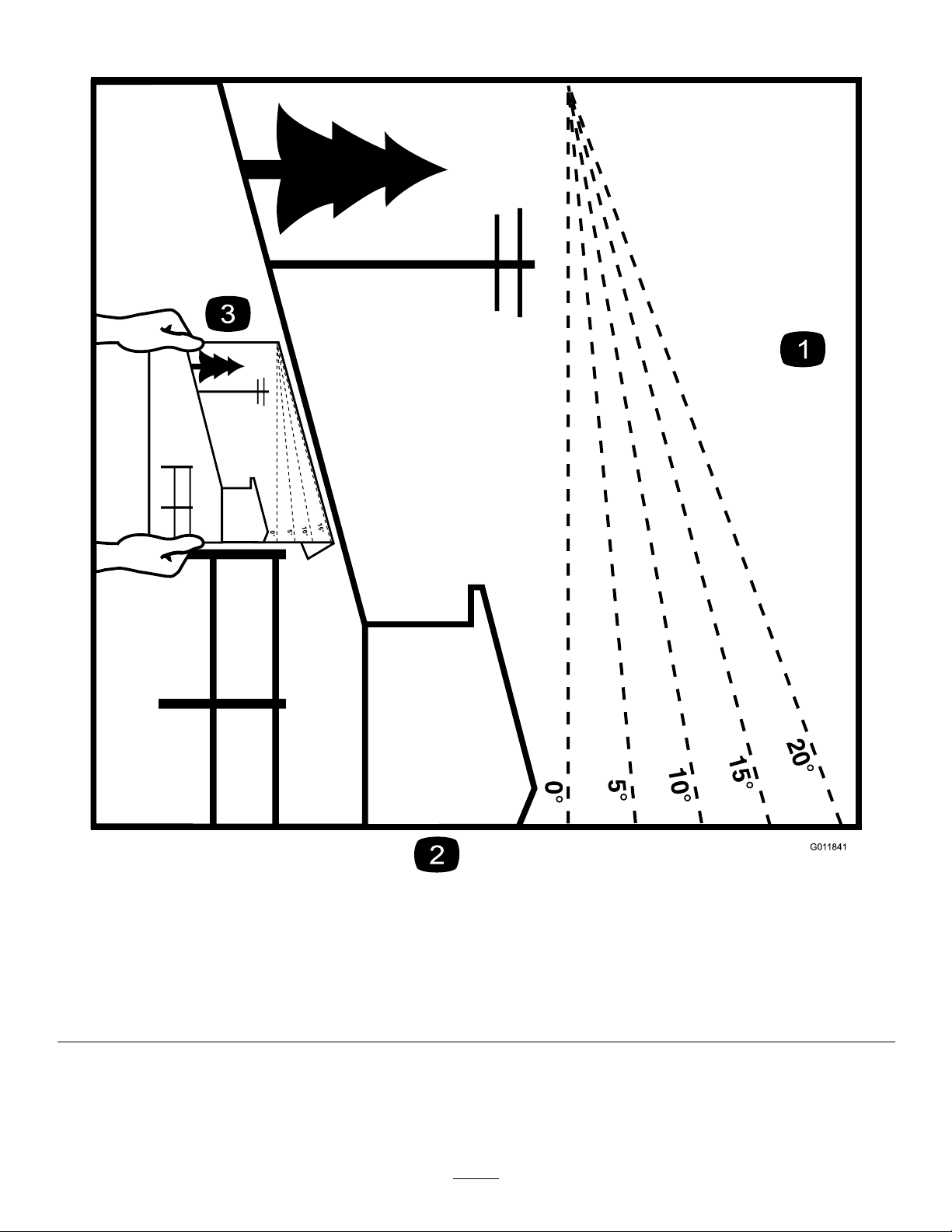
SlopeIndicator
G011841
Figure3
Thispagemaybecopiedforpersonaluse.
1.Themaximumslopeyoucansafelyoperatethemachineonis15degrees.Usetheslopecharttodeterminethedegreeofslope
ofhillsbeforeoperating.Donotoperatethismachineonaslopegreaterthan15degrees.Foldalongtheappropriateline
tomatchtherecommendedslope.
2.Alignthisedgewithaverticalsurface,atree,building,fencepole,etc.
3.Exampleofhowtocompareslopewithfoldededge.
6
Page 7
SafetyandInstructionalDecals
Safetydecalsandinstructionsareeasilyvisibletotheoperatorandarelocatednearanyareaofpotential
danger.Replaceanydecalthatisdamagedorlost.
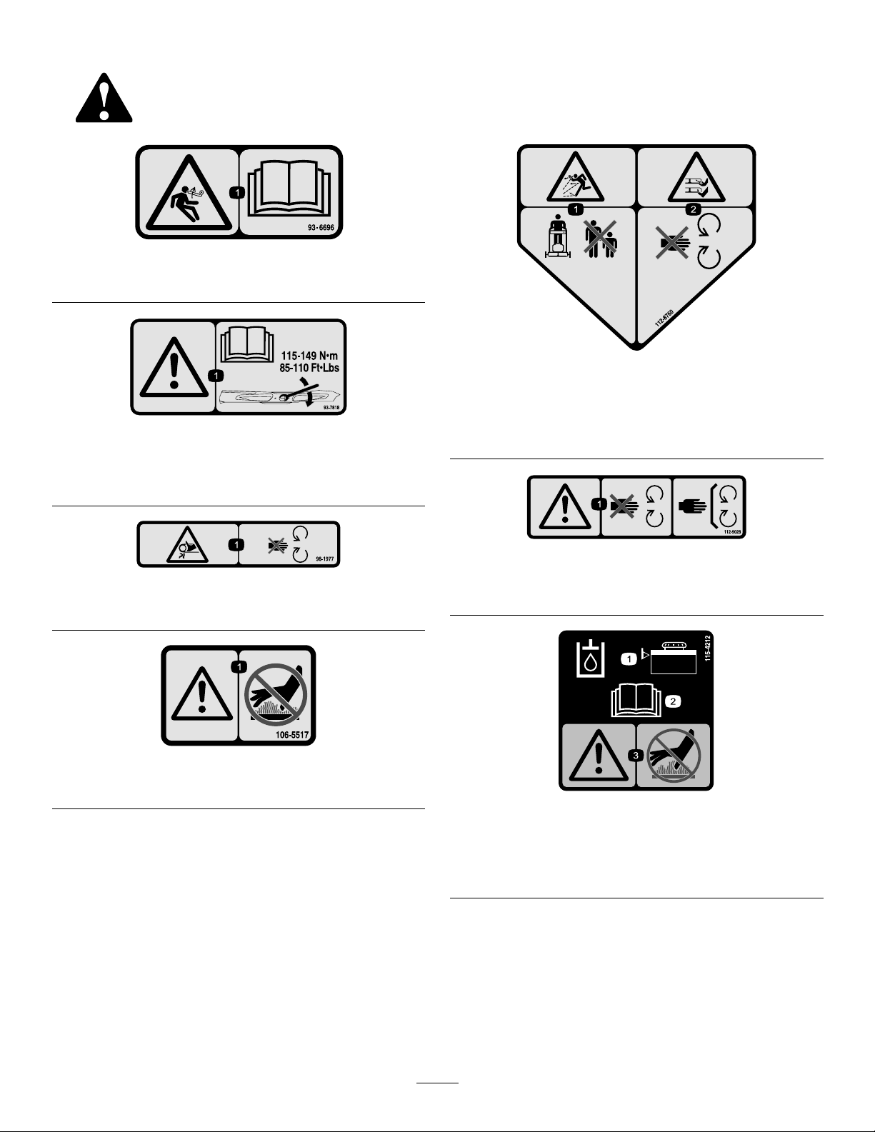
93–6696
1.Storedenergyhazard—readtheOperator'sManual.
93-7818
1.Warning—readtheOperator'sManualforinstructionson
torquingthebladebolt/nutto1 15to149N∙m(85to110
ft-lb).
112-8760
1.Thrownobjecthazard—keepbystandersasafedistance
fromthemachine.
2.Cutting/dismembermentofhandorfoot—stayawayfrom
movingparts.
98-1977
1.Entanglementhazard,belt—stayawayfrommovingparts.
106-5517
1.Warning—donottouchthehotsurface.
112-9028
1.Warning—stayawayfrommovingparts;keepallguardsin
place.
115-4212
1.Hydraulic-uidlevel
2.ReadtheOperator's
Manual.
3.Warning—donottouchthe
hotsurface.
7
Page 8
NVXXXXXX
1
2
3
4 5 6 7
116-8813
1.Hopperupindicator5.Parkingbrake
2.Battery6.Neutral
3.Hourmeter
4.PTO
7.Operator-presenceswitch
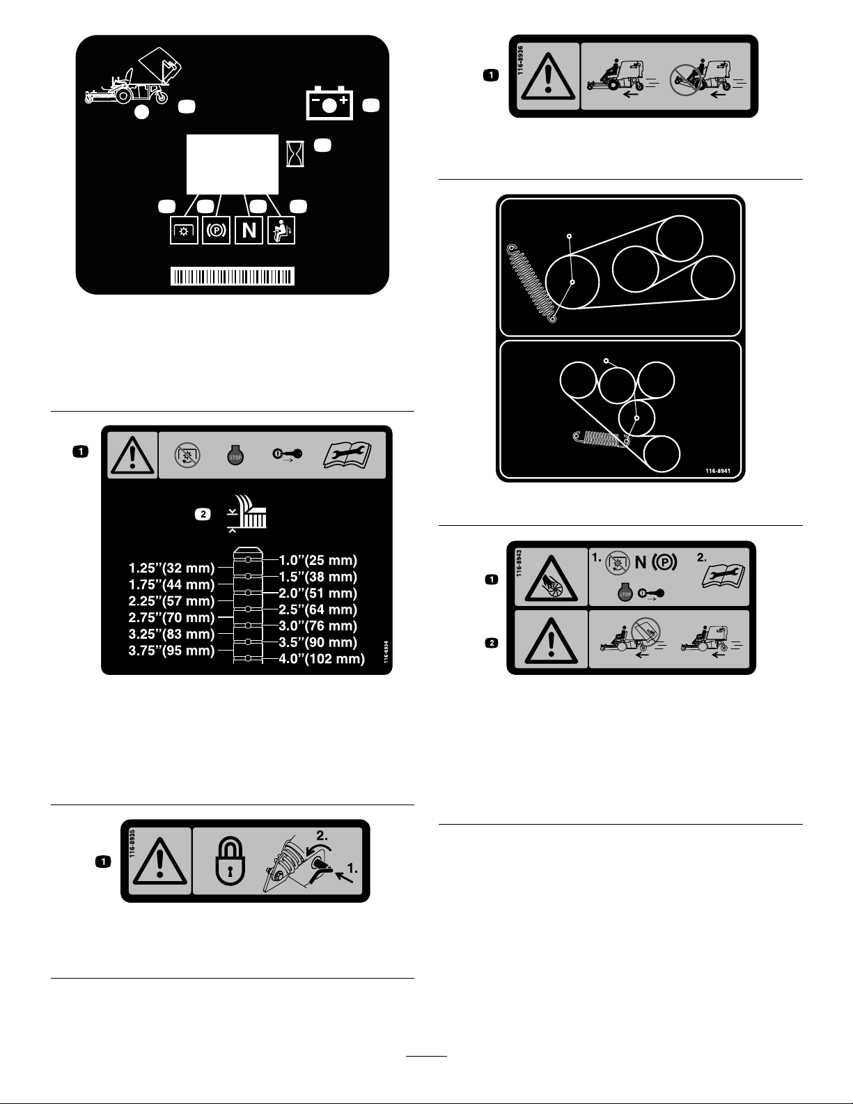
116-8936
1.Danger—donotoperatewithdeckintilt-upposition.
116-8941
116-8934
1.Warning—disengage
bladeclutch,shutoff
theengine,andremove
thekeybeforemaking
adjustments,servicing,or
cleaningthedeck.
1.Warningfoldingdeckhazard—lockthepivotjointby
pushinginwardandrotatingtowardthefrontofthedeck.
116-8935
2.Heightofcut.
116-8943
1.Rotatingbladeshazard-DisengagePTO,movethe
speed-controllevertoNEUTRAL,engagetheparkingbrake,
shutofftheengine,andremovethekeybeforeleavingthe
operator’sposition.Readtheinstructionsbeforeservicing
orperformingmaintenance.
2.Danger—donotoperatewiththemowerhopperinthe
raisedposition.
8
Page 9
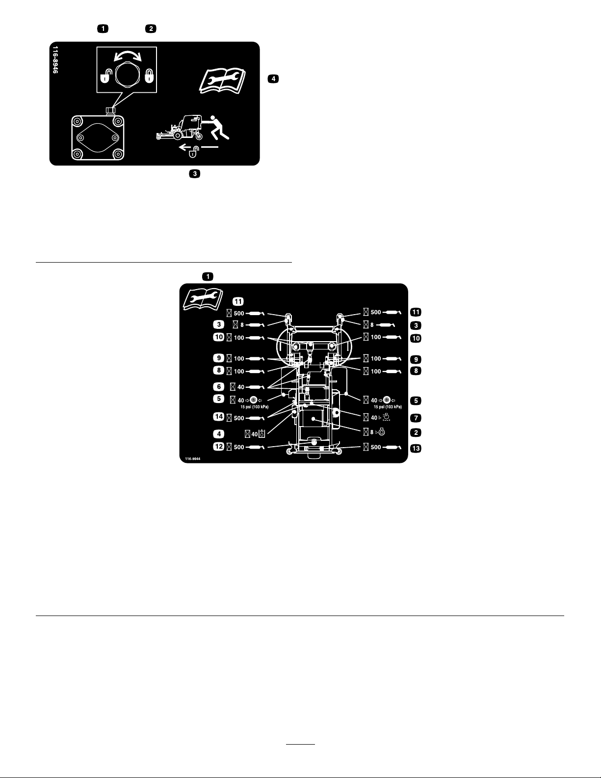
116-8946
1.Rotatecounterclockwise
torelease
2.Rotateclockwisetolock4.Readtheinstructions
3.Unlocktopushthe
machine
beforeservicingor
performingmaintenance.
116-9044
1.ReadtheOperator’sManualbeforeperformingany
maintenance.
2.Checkengineoilevery8hours.9.Greasethedeckpivotsevery100hours.
3.Greasefrontcasterwheelbearingsevery8hours.10.Checkthegearboxoilevery100hours(useonlyMobil1
4.Checkthehydraulic-uidlevelevery40hours(onlyuse
recommendedhydrooil).
5.Checkthetirepressureevery40hours.12.Greasetherearcasterpivotevery500hours.
6.GreasethedeckdrivePTOevery40hours.13.Greasetherearcasterwheelevery500hours.
7.Checktheaircleanerevery40hours.14.Greasethebeltidlersevery500hours.
8.Greasethedecklockmechanismevery100hours.
75W-90gearoil).
11.Greasethefrontcasterpivotsevery500hours.
9
Page 10
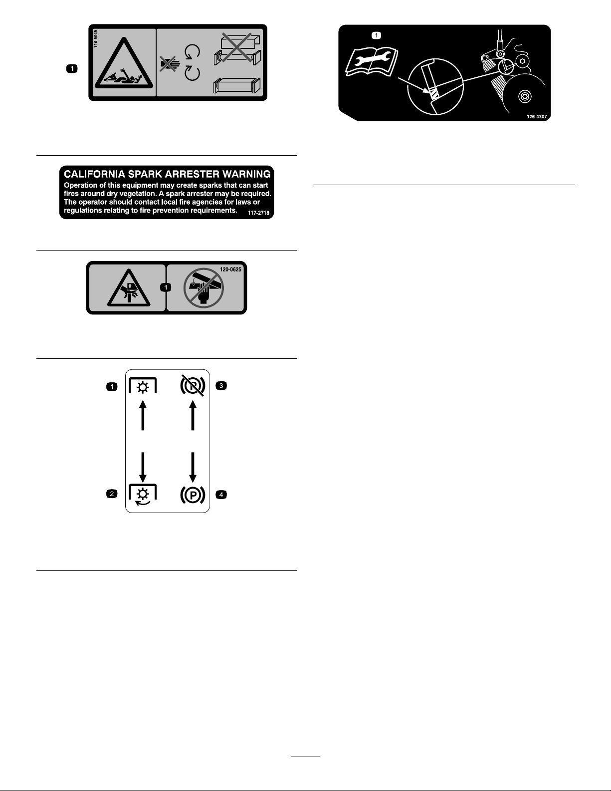
116-9049
1.Rotatingdrivelinehazard—keepalldrivelinesshieldsin
place.Securelyattachbothendsofthedriveline.
117–2718
120-0625
1.Pinchpoint,hand—keephandsaway.
126-4207
1.RefertotheOperator’sManualforadjustmentprocedure.
WhenthePTOisengaged,theidlerarmpositionmustbe
inhatchedareaoranadjustmentisrequired.
MoldedinLHConsole
1.PTO—disengage
2.PTO—engage
3.Parkingbrake—release
4.Parkingbrake—engage
10
Page 11
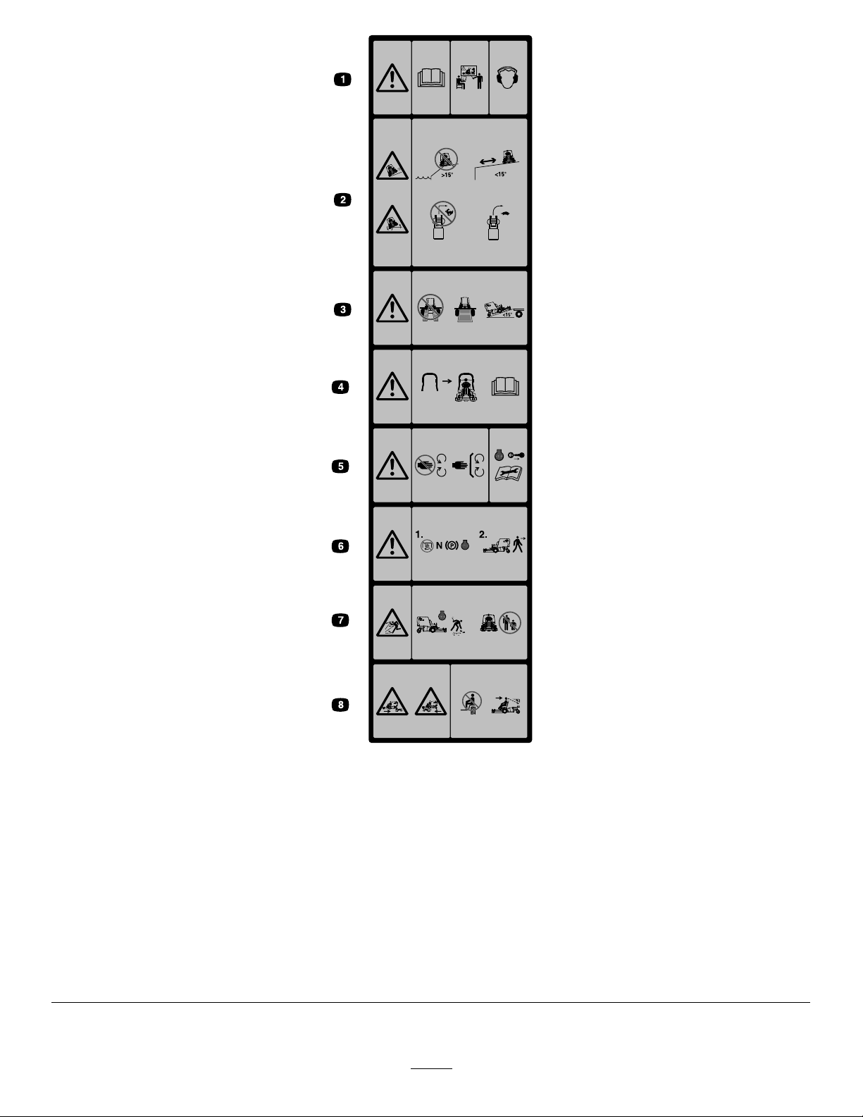
MoldedintoFrontofHopper
1.Warning—ReadtheOperator’sManual.Donotoperatethis
machineunlessyouaretrained.Wearhearingprotection.
2.Sliding,tippinghazard—Donotusethemachinenear
drop-offswithslopesgreaterthan15degrees,usethe
machineasafedistanceformdrop-offsonslopeslessthan
15degrees;Donotturnsharplywhiletravelingfast,drive
slowlywhenturning.
3.Warning—Donotusedualramps,useonepiecerampswhen
transportingmachine;Donotuserampswithinclination
greaterthan15degrees.
4.Arollbarisavailable;useitforareaswherethereareslopes,
drop-offs,orwater.
5.Warning—Stayawayfrommovingparts;keepallguards
inplace.Shutofftheengineandremovethekeybefore
adjusting,servicing,orcleaning.
6.Warning—DisengagethePTO,movethespeed-controllever
toNEUTRALposition,engagetheparkingbrake,andshutoff
theenginebeforeleavingtheoperator’sposition.
7.Thrownobjecthazard—Pickupobjectsthatcouldbethrown
bymower.Donotoperatewhenpeopleandpetsareinthe
area.Keepthedeectorinplace.
8.Crushing/dismembermenthazardofbystanders—Donot
carrypassengers,andlookforwardanddownwhenoperating
themachine,andlookbehindanddownwhenreversing.
11
Page 12
BatterySymbols
Someorallofthesesymbolsareonyourbattery
1.Explosionhazard
2.Nore,opename,or
smoking
3.Causticliquid/chemical
burnhazard
4.Weareyeprotection.9.Flusheyesimmediately
5.ReadtheOperator's
Manual.
6.Keepbystandersasafe
7.Weareyeprotection;
8.Batteryacidcancause
10.Containslead;donot
distancefromthebattery.
explosivegasescan
causeblindnessandother
injuries.
blindnessorsevereburns.
withwaterandgetmedical
helpfast.
discard
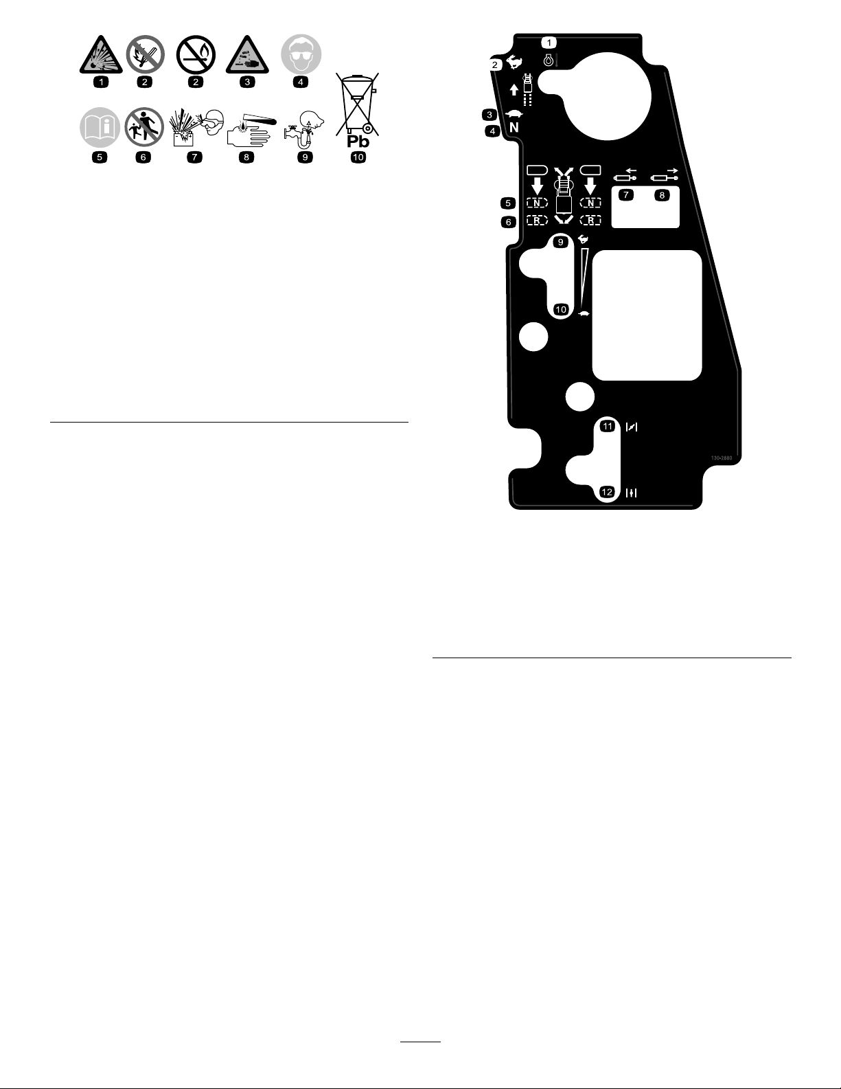
130-2880
1.Enginetemperature7.Retractthepiston
2.Fast8.Extendthepiston
3.Slow
4.Neutral
5.Neutral
6.Reverse
9.Fast
10.Slow
11.Choke—closed/on
12.Choke—open/off
12
Page 13
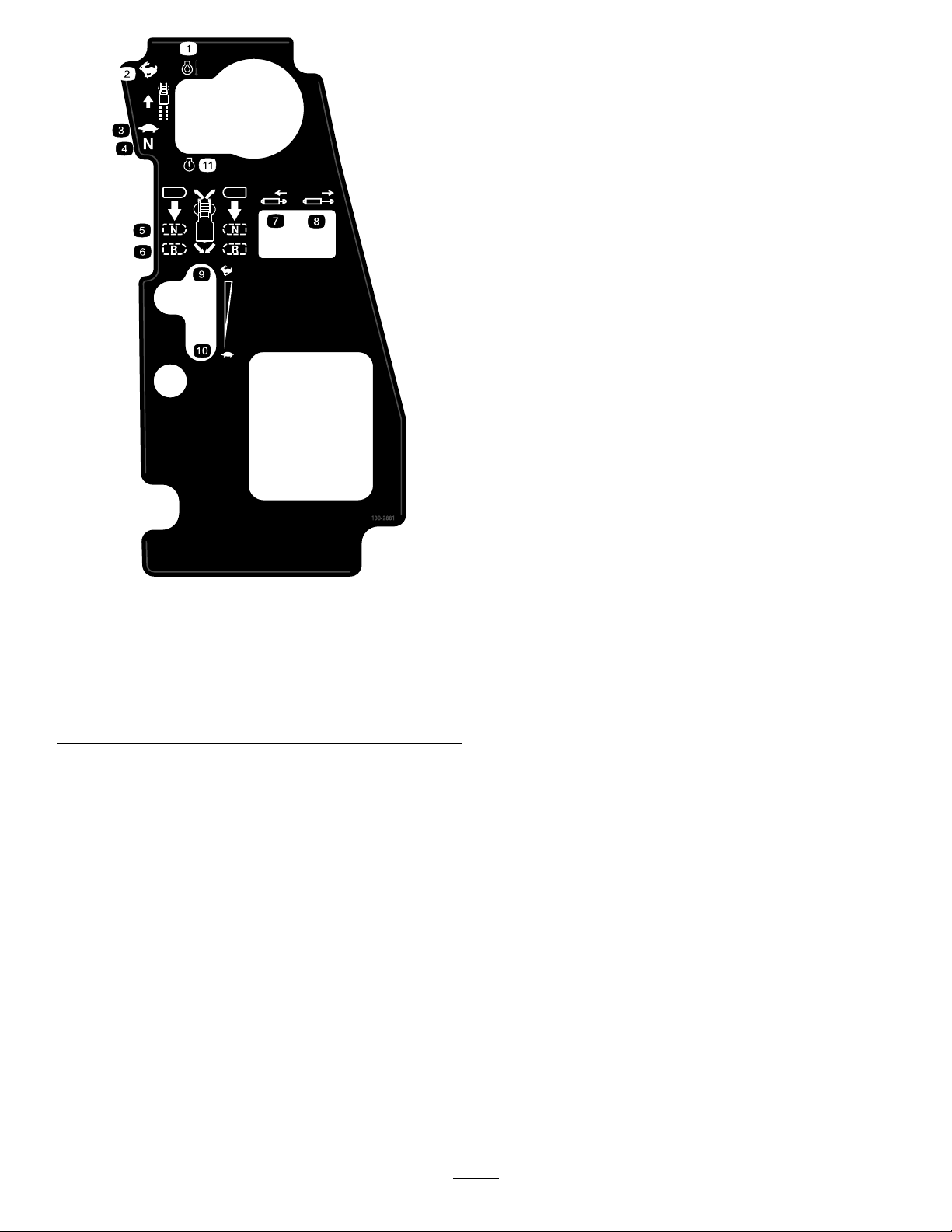
130–2881
1.Enginetemperature7.Retractthepiston
2.Fast8.Extendthepiston
3.Slow
4.Neutral
5.Neutral11.MILtoggleswitch
6.Reverse
9.Fast
10.Slow
13
Page 14
ProductOverview
Motion-ControlLevers
Themotion-controlleversareusedtodrivethemachine
forward,reverse,andturneitherdirection(Figure4).
Speed-ControlLever
Thespeed-controlleversetsmaximumforwardspeedofthe
machine(Figure4).Movingspeed-controlleverrearwardto
theNEUTRALpositionplacesthedrivesystemintoneutral.
ThrottleControl
Thethrottleisusedtocontrolenginespeed.Thethrottle
controlisvariablebetweenFASTandSLOW.
ChokeControl(NotonEFImachines)
Thechokeisusedtoaidinstartingacoldengine.Movethe
choketotheCLOSED/ONpositiontostartacoldengine.
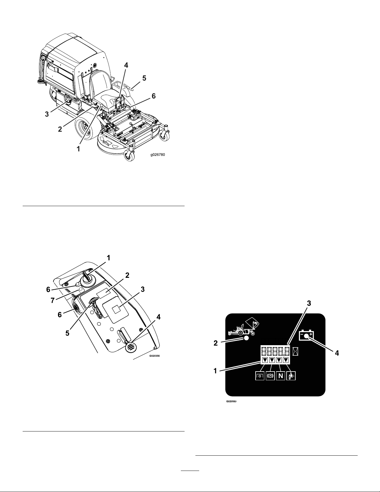
Figure4
1.Speed-controllever
2.Controls5.PTO-engagementlever
3.Fuelcap6.Parking-brakelever
4.Motion-controllevers
Controls
Becomefamiliarwithallthecontrolsbeforeyoustartthe
engineandoperatethemachine(Figure4andFigure5).
Note:DonotrunawarmenginewithchokeintheON
position.
BrakeLever
Thebrakeleverengagesaparkingbrakeonthedrivewheels
(Figure4).
IgnitionSwitch
Thisswitchisusedtostartthemowerengineandhas3
positions:START,RUN,andOFF.
HourMeter
Thehourmeterrecordsthenumberofhourstheenginehas
operated.Thehourmeterisrecordingwhenthedecimal
pointisashinginthehour/voltagedisplay.Usethesetimes
forschedulingregularmaintenance(Figure6).
Figure5
1.Ignitionswitch5.Throttle
2.Hopperswitch6.Engine-oiltemperature
3.Messagedisplay
4.Choke(notonEFI
machines)
7.Checkenginelight(EFI
lightandbuzzer
machinesonly)
Figure6
1.Safety-interlockindicators
2.Hopperup
3.Hour/voltagedisplay
4.Lowvoltageindicatorlight
14
Page 15

Safety-InterlockIndicators
Specications
Therearesymbolsonthehourmeterandtheindicatewitha
blacktrianglethattheinterlockcomponentisinthecorrect
position(Figure6).
Fuel-ShutoffValve
Closethefuel-shutoffvalve(underthehopper)when
transportingorstoringthemower.
PTO-EngagementLever
ThePTO-engagementleverisusedtoengagethebladesand
theblower.Pulltheleveruptoengagethebladesandblower.
Todisengagethebladesblower,pushthePTO-engagement
leverdown.
BatteryIndicatorLight
WhentheignitionkeyisinitiallyturnedtotheRUNposition
forafewseconds,thebatteryvoltagewillbedisplayedinthe
areawherethehoursarenormallydisplayed.
Thebatterylightturnsonwhentheignitionisturnedonand
whenthechargeisbelowthecorrectoperatinglevel(Figure
6).
EngineOilTemperatureLightand
Buzzer
Note:Specicationsanddesignaresubjecttochange
withoutnotice.
Width:
WithoutMower
Deck
WithMowerDeck
42-inchMower
Deck
108.2cm(42.6
inches)
109.7cm(43.2
inches)
48-inchMower
Deck
108.2cm(42.6
inches)
125.0cm(49.2
inches)
Length:
42-inchMower
Deck
WithoutMower
Deck
MowerDeck—Up
Mower
Deck—Down
170.9cm(67.3
inches)
209.3cm(82.4
inches)
233.2cm(91.8
inches)
48-inchMower
Deck
170.9cm(67.3
inches)
207.6cm(81.8
inches)
240.0cm(94.5
inches)
Height:
42-inchMowerDeck48-inchMowerDeck
130.0cm(51.2inches)130.0cm(51.2inches)
Weight:
Theengineoiltemperaturelightmonitorsthetemperatureof
theengineoil.Anilluminatedengineoiltemperaturelightand
intermittentbuzzingsoundsignalstheengineisoverheating.
ElectronicControlUnitMalfunction
IndicatorLight
Theelectroniccontrolunit(ECU)continuouslymonitorsthe
operationoftheEFIsystem.
Ifthesystemdetectsaproblemorfault,themalfunction
indicatorlight(MIL)illuminates.
TheMILislocatedintherightconsolepanel.
IftheMILilluminates,performtheinitialtroubleshooting
checks;refertotheMILsectioninTroubleshooting(page57).
Ifthesechecksdonotcorrecttheproblem,furtherdiagnosis
andservicingbyanAuthorizedServiceDealerisnecessary.
Attachments/Accessories
AselectionofToroapprovedattachmentsandaccessoriesis
availableforusewiththemachinetoenhanceandexpand
itscapabilities.ContactyourAuthorizedServiceDealeror
Distributororgotowww .Toro.comforalistofallapproved
attachmentsandaccessories.
42-inchMowerDeck48-inchMowerDeck
517kg(1,140lb)531kg(1,170lb)
15
Page 16

Operation
Note:Determinetheleftandrightsidesofthemachine
fromthenormaloperatingposition.
DANGER
Incertainconditionsduringfueling,static
electricitycancauseasparkwhichcanignitethe
gasolinevapors.Areorexplosionfromgasoline
canburnyouandothersandcandamageproperty.
AddingFuel
•Forbestresults,useonlyclean,fresh(lessthan30days
old),unleadedgasolinewithanoctaneratingof87or
higher((R+M)/2ratingmethod).
•Ethanol:Gasolinewithupto10%ethanol(gasohol)
or15%MTBE(methyltertiarybutylether)byvolume
isacceptable.EthanolandMTBEarenotthesame.
Gasolinewith15%ethanol(E15)byvolumeisnot
approvedforuse.Neverusegasolinethatcontainsmore
than10%ethanolbyvolume,suchasE15(contains15%
ethanol),E20(contains20%ethanol),orE85(contains
upto85%ethanol).Usingunapprovedgasolinemay
causeperformanceproblemsand/orenginedamage,
whichmaynotbecoveredunderwarranty.
•Donotusegasolinecontainingmethanol.
•Donotstorefueleitherinthefueltankorfuelcontainers
overthewinterunlessyouuseafuelstabilizer.
•Donotaddoiltogasoline.
DANGER
Incertainconditions,gasolineisextremely
ammableandhighlyexplosive.Areorexplosion
fromgasolinecanburnyouandothersandcan
damageproperty.
•Fillthefueltankoutdoors,inanopenarea,
whentheengineiscold.Wipeupanygasoline
thatspills.
•Neverllthefueltankinsideanenclosedtrailer.
•Donotllthefueltankcompletelyfull.Add
gasolinetothefueltankuntilthelevelis6to13
mm(1/4to1/2inch)belowthebottomofthe
llerneck.Thisemptyspaceinthetankallows
gasolinetoexpand.
•Neversmokewhenhandlinggasoline,andstay
awayfromanopenameorwheregasoline
fumesmaybeignitedbyaspark.
•Storegasolineinanapprovedcontainerand
keepitoutofthereachofchildren.Neverbuy
morethana30-daysupplyofgasoline.
•Donotoperatewithouttheentireexhaust
systeminplaceandinproperworkingcondition.
•Alwaysplacegasolinecontainersontheground
awayfromyourvehiclebeforelling.
•Donotllgasolinecontainersinsideavehicleor
onatruckortrailerbed,becauseinteriorcarpets
orplastictruck-bedlinersmayinsulatethe
containerandslowthelossofanystaticcharge.
•Whenpractical,removegas-poweredequipment
fromthetruckortrailerandfueltheequipment
withthewheelsontheground.
•Ifthisisnotpossible,thenfuelsuchequipment
onatruckortrailerfromaportablecontainer,
ratherthanfromagasoline-dispensernozzle.
•Ifagasolinedispensermustbeused,keepthe
nozzleincontactwiththerimofthefueltank
orcontaineropeningatalltimesuntilfuelingis
complete.
WARNING
Gasolineisharmfulorfatalifswallowed.Long-term
exposuretovaporscancauseseriousinjuryand
illness.
•Avoidprolongedbreathingofvapors.
•Keepfaceawayfromnozzleandgastankor
conditionerbottleopening.
•Avoidcontactwithskin;washoffspillswith
soapandwater.
UsingFuelStabilizer/Conditioner
Useafuelstabilizer/conditionerinthemachinetokeep
thefuelfreshduringstorageof90daysorless.Ifyouare
storingthemachineforlonger,drainthefueltank;seeyour
authorizedservicedealer.
Important:Donotusefueladditivescontaining
methanolorethanol.
Addthecorrectamountoffuelstabilizer/conditionertothe
fuel,andfollowthedirectionsofthemanufacturer.
Note:Fuelstabilizer/conditionerismosteffectivewhen
mixedwithfreshgasoline.Tominimizethechanceofvarnish
depositsinthefuelsystem,usefuelstabilizeratalltimes.
16
Page 17
FillingtheFuelTank
G009027
1
2
1.Parkthemachineonlevelground.
2.Shuttheengineoffandsettheparkingbrake.
3.Cleanaroundthefuel-tankcapandremoveit.Add
regularunleadedgasolinetothefueltankuntilthelevel
is6to13mm(1/4to1/2inch)belowthebottom
ofthellerneck.Thisspaceinthetankallowsthe
gasolinetoexpand.Donotllthefueltankcompletely
full;referto(Figure4).
CheckingtheEngine-OilLevel
Beforeyoustarttheengineandusethemachine,check
theoillevelintheenginecrankcase;refertoCheckingthe
Engine-OilLevel(page33).
BreakinginaNewMachine
Newenginestaketimetodevelopfullpower.Mowerdecks
anddrivesystemshavehigherfrictionwhennew,placing
additionalloadontheengine.Allow40to50hoursof
break-intimefornewmachinestodevelopfullpowerand
bestperformance.
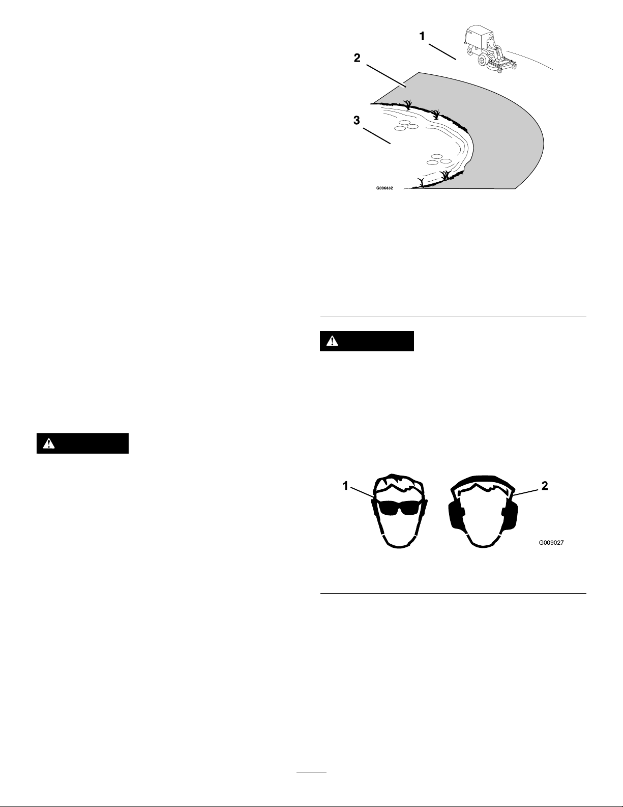
1.Safezone—usethe
machinehereonslopes
lessthan15degreesor
atareas.
2.Dangerzone—useawalk
behindmowerand/ora
handtrimmeronslopes
greaterthan15degrees,
neardrop-offsandwater.
CAUTION
Figure7
3.Water
ThinkSafetyFirst
Pleasereadallsafetyinstructionsandsymbolsinthesafety
section.Knowingthisinformationcouldhelpyouor
bystandersavoidinjury.
DANGER
Operatingonwetgrassorsteepslopescancause
slidingandlossofcontrol.
Wheelsdroppingoveredgescancauserollovers,
whichmayresultinseriousinjury,death,or
drowning.
Toavoidlossofcontrolandpossibilityofrollover:
•Donotoperateneardrop-offsornearwater.
•Donotoperateonslopesgreaterthan15degrees.
•Reducespeedanduseextremecautionon
slopes.
•Avoidsuddenturnsorrapidspeedchanges.
Thismachineproducessoundlevelsinexcessof
85dBAattheoperator’searandcancausehearing
lossthroughextendedperiodsofexposure.
Wearhearingprotectionwhenoperatingthis
machine.
Theuseofprotectiveequipmentforeyes,ears,feet,andhead
isrecommended.
Figure8
1.Weareyeprotection.2.Wearhearingprotection.
17
Page 18
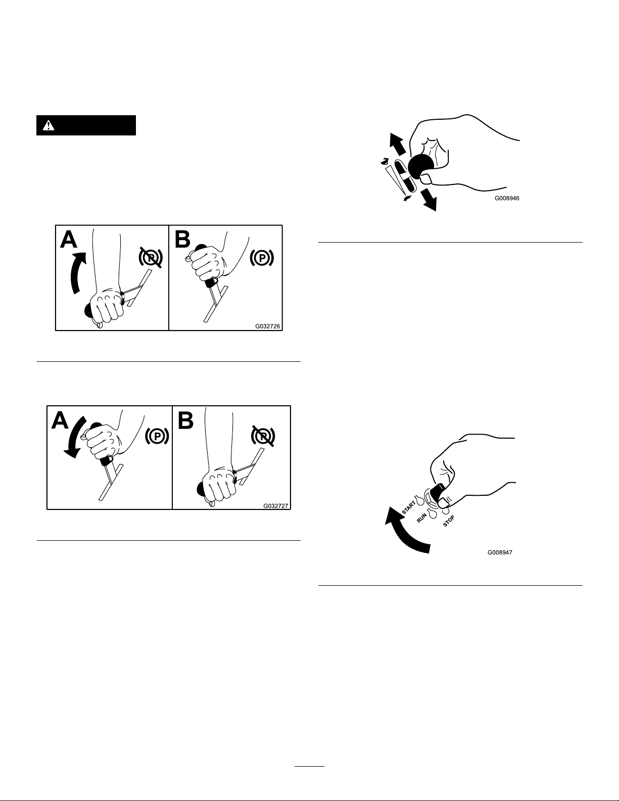
OperatingtheParkingBrake
G008946
START
RUN
STOP
G008947
OperatingtheThrottle
Alwayssettheparkingbrakewhenyoustopthemachineor
leaveitunattended.
SettingtheParkingBrake
WARNING
Theparkingbrakemaynotholdmachineparkedon
aslopeandcouldcausepersonalinjuryorproperty
damage.
Donotparkonslopesunlessthewheelsare
chockedorblocked.
Figure9
ReleasingtheParkingBrake
ThethrottlecontrolcanbemovedbetweentheFASTand
SLOWpositions(Figure11).
Alwaysusethemiddlepositionwhenturningonthemower
deckandblowerwiththePTO-engagementlever.
Figure11
OperatingtheIgnitionSwitch
1.TurntheignitionkeytotheSTARTposition(Figure
12).Whentheenginestarts,releasethekey.
Important:Donotengagethestarterformore
than10secondsatatime.Iftheenginefailsto
start,allowa60secondcool-downperiodbetween
attempts.Failuretofollowtheseinstructionscan
burnoutthestartermotor.
Note:Additionalstartingcyclesmayberequired
whenstartingtheengineforthersttimeafterthefuel
systemhasbeencompletelywithoutfuel.
Figure10
Figure12
2.Toshutofftheengine,turntheignitionkeytothe
STOPposition.
18
Page 19
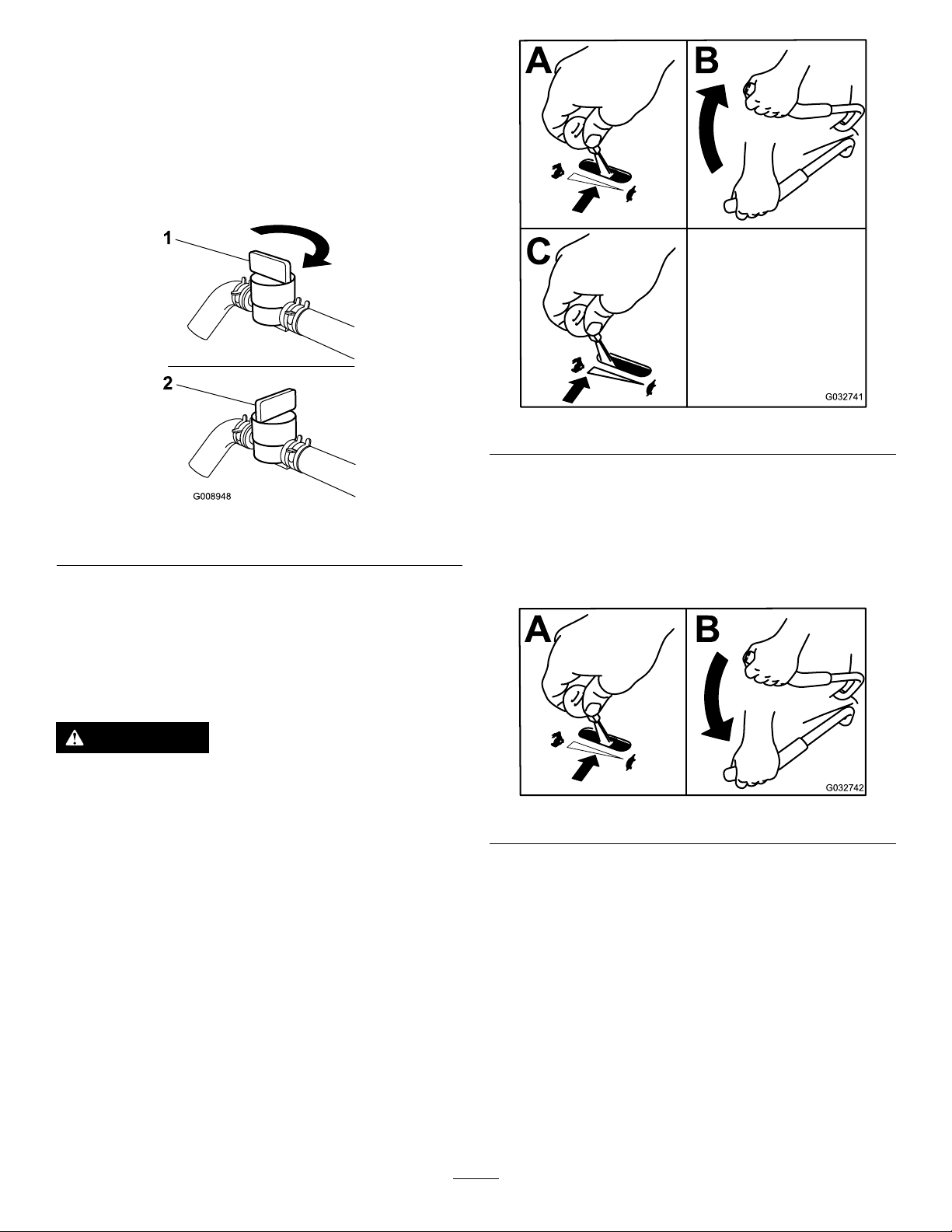
UsingtheFuel-ShutoffValve
G008948
1
2
Thefuel-shutoffvalveislocatedunderthehopper.Raisethe
hoppertoaccessit.
Closethefuel-shutoffvalvefortransport,maintenance,and
storage.
Ensurethatthefuel-shutoffvalveisopenwhenstartingthe
engine.
Figure13
1.On2.Off
Figure14
DisengagingthePTO-Engagement
Lever
1.SetthethrottletotheMIDDLEposition.
2.PushPTOleverdowntotheSTOPpositionstopping
thebladesandblower.
Operatingthe PTO-EngagementLever
ThePTO-engagementleverstartsandstopsthemower
bladesandblower.
WARNING
Anuncovereddischargeopeningallowsobjectsto
bethrownatyouorbystanders.Also,contactwith
theblowerbladescouldoccur.Thrownobjectsor
bladecontactcancauseseriousinjuryordeath.
Neveroperatethemachinewiththehopperor
hopperdoorraised,removed,oraltered.
EngagingthePTO-EngagementLever
1.SetthethrottletotheMIDDLEposition.
2.PullthePTOleverupwarduntillockedovercenter.
3.PlacethethrottleintheFASTpositiontobeginmowing.
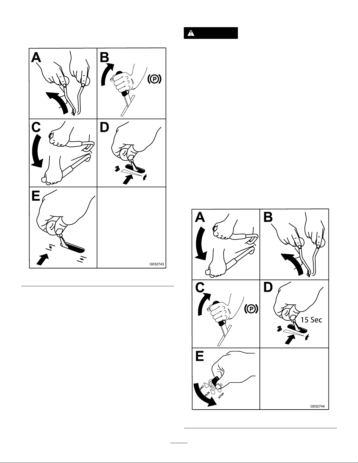
StartingandStoppingthe Engine
StartingtheEngine
1.Movethespeed-controllevertotheNEUTRALposition.
2.Settheparkingbrake;refertoSettingtheParking
Brake(page18).
Figure15
3.MovethePTO-engagementlevertotheOFFposition
(Figure16).
4.MovethethrottlelevermidwaybetweentheSLOWand
FASTpositions.
19
Page 20
5.Onacoldengine,pushthechokeleverforwardinto
theCLOSED/ONposition(notonEFIengines).On
awarmengine,leavethechokeintheOPEN/OFF
position.
StoppingtheEngine
CAUTION
Childrenorbystandersmaybeinjuredifthey
moveorattempttooperatethemachinewhileitis
unattended.
Alwaysremovetheignitionkeyandsettheparking
brakewhenleavingthemachineunattended,even
ifjustforafewminutes.
Important:Makesurethatthefuel-shutoffvalveis
closedbeforetransportingorstoringthemachine,as
fuelleakagemayoccur.Settheparkingbrakebefore
transporting.Makesurethatyouremovethekeyasthe
fuelpumpmayrunandcausethebatterytolosecharge.
1.DisengagethePTO.
2.Movethespeed-controllevertotheNEUTRALposition.
3.Engagetheparkingbrake.
4.Placethethrottletothemiddleposition.
5.Allowtheenginetorunforaminimumof15seconds,
thenturntheignitionswitchtotheOFFpositionto
shutofftheengine.
6.Removethekey.
Figure16
6.TurntheignitionkeytotheSTARTposition(Figure
12).Whentheenginestarts,releasethekey.
Important:Donotcranktheenginecontinuously
formorethan10secondsatatime.Iftheengine
doesnotstart,wait60secondsbetweenstarting
attempts.Failuretofollowtheseguidelinescan
burnoutthestartermotor.
Note:Additionalstartingcyclesmayberequired
whenstartingtheengineforthersttimeafterthefuel
systemhasbeenwithoutfuelcompletely.
7.IfthechokeisintheCLOSED/ONposition,gradually
returnchoketotheOPEN/OFFpositionastheengine
warmsup.
Figure17
20
Page 21

7.Closethefuelshut-offvalvewhenyoudonotusethe
machineforafewdays,whentransporting,orwhen
youparkthemachineinsideabuilding.
TheSafetyInterlockSystem
CAUTION
Ifthesafetyinterlockswitchesaredisconnectedor
damaged,themachinecouldoperateunexpectedly,
causingpersonalinjury.
•Donottamperwiththeinterlockswitches.
•Checktheoperationoftheinterlockswitches
dailyandreplaceanydamagedswitchesbefore
operatingthemachine.
UnderstandingtheSafetyInterlock
System
Thesafetyinterlocksystemisdesignedtopreventtheengine
fromstartingunlessthefollowingoccurs:
•Theparkingbrakeisengaged.
•ThePTO-engagementleverisdisengaged.
•Thespeed-controlleverisintheNEUTRALposition.
Thesafetyinterlocksystemisdesignedtoshutofftheengine
whenyourisefromtheseatwhenthePTOisengaged.
Thehourmeterhassymbolstonotifytheuserwhenthe
interlockcomponentisinthecorrectposition.Whenthe
componentisinthecorrectposition,atrianglelightsupin
thecorrespondingsquare.
TestingtheSafetyInterlockSystem
ServiceInterval:Beforeeachuseordaily
Testthesafetyinterlocksystembeforeyouusethemachine
eachtime.Ifthesafetysystemdoesnotoperateasdescribed
below,haveanAuthorizedServiceDealerrepairthesafety
systemimmediately.
1.Sittingontheseat,engagetheparkingbrake,move
thePTO-engagementlevertoON,andmovethe
speed-controllevertotheNEUTRALposition.Try
startingtheengine;theengineshouldnotcrank.
2.Sittingontheseat,engagetheparkingbrakeand
movethePTO-engagementlevertoOFF.Movethe
speed-controlleveroutoftheNEUTRALposition.Try
startingtheengine;theengineshouldnotcrank.
3.Sittingontheseat,disengagetheparkingbrake,move
thePTO-engagementlevertoOFF,andmovethe
speed-controllevertotheNEUTRALposition.Try
startingtheengine;theengineshouldnotcrank.
4.Sittingontheseat,engagetheparkingbrake,move
thePTO-engagementlevertoOFF,andmovethe
speed-controllevertotheNEUTRALposition.Start
theengine.Whiletheengineisrunning,releasethe
parkingbrake,engagethePTO-engagementlever,and
riseslightlyfromtheseat;theengineshouldshutoff.
5.Sittingontheseat,engagetheparkingbrake,move
thePTO-engagementlevertoOFF,andmovethe
speed-controllevertotheNEUTRALposition.Start
theengine.Movethespeed-controlleverforward;the
engineshouldshutoff.
DrivingForwardorBackward
Thethrottlecontrolregulatestheenginespeedasmeasured
inrpm(revolutionsperminute).Placethethrottlecontrolin
theFASTpositionforbestperformance.Alwaysoperatein
thefullthrottlepositionwhenmowing.
Figure18
1.Triangleslightupwhen
theinterlockcomponents
areinthecorrectposition
2.Hopperup4.Lowvoltageindicatorlight
3.Hour/voltagedisplay
CAUTION
Machinecanspinveryrapidly.Youmaylosecontrol
ofmachineandcausepersonalinjuryordamage
tothemachine.
•Usecautionwhenmakingturns.
•Slowdownthemachinebeforemakingsharp
turns.
DrivingForward
Note:Tobeginmovement(forwardorbackward)youmust
beintheseat,thebrakelevermustbedisengaged(pushed
down)beforethespeed-controllevercanmoveforward;
otherwise,theengineshutsoff.
Tostopthemachine,pullthespeed-controllevertothe
NEUTRALposition.
1.Starttheengine.
21
Page 22

2.Releasetheparkingbrake;refertoReleasingthe
ParkingBrake(page18).
3.Tomoveforwardinastraightlinemovethe
speed-controlleverforward.
Note:Themachinemovesfasterthefartherthe
speed-controlleverismovedawayfromNEUTRAL.
4.Toturnleftorright,pull1ofthesteeringleversback
towardneutralinthedirectiondesired.
5.Tostopthemachine,pullthespeed-controlleverback
totheNEUTRALposition.
DrivingBackward
1.Tomoverearwardinastraightline,pullbothsteering
leversrearwardequally.
Toturnleftorright,releasepressureonthesteering
levertowardthedirectiondesired.
RaisingtheMowerDeckinto ServicePosition
1.Shutofftheengine,waitforallmovingpartstostop,
removethekey,andengagetheparkingbrake.
WARNING
Incorrectlyraisingorloweringamowerdeck
canbedangerous.Adroppedmowerdeckcan
resultinaseriousinjuryorpropertydamage.
•Alwaysraiseandlowerthemowerdeckon
at,dryground,freeofanyobstructions.
•Firmlygraspthemower-deck-lifthandle
andlowerinaslowcontrolledmanner.
•Alwaysmakesurethatthemowerdeckis
securelylatchedintheupordownposition.
2.Tostopthemachine,releasethesteeringleverstothe
NEUTRALposition.
StoppingtheMachine
1.Pullthespeed-controlleverbacktotheNEUTRAL
position,disengagethePTO-engagementlever,and
turntheignitionkeytotheOFFposition.
2.Settheparkingbrakewhenyouleavethemachine;
refertoSettingtheParkingBrake(page18).
3.Removethekeyfromtheignitionswitch.
CAUTION
Childrenorbystandersmaybeinjuredifthey
moveorattempttooperatethemachinewhileitis
unattended.
Alwaysremovetheignitionkeyandsettheparking
brakewhenleavingthemachineunattended,even
ifjustforafewminutes.
2.Releasethemowerdecklockingpinsoneachside
(Figure19).
Figure19
1.Deck-lifthandle
2.Rotatethemowerdecklockingpintowardtherearandpull
outwardtounlock.
3.Pushthedecklockingpininandrotateittowardthefront
tolock.
3.Usingthedeck-lifthandle,liftthedeckupandlatchit
intheupposition(Figure20).
Note:Thelatchislocatedatthefrontcenterofthe
seat.
22
Page 23

Figure20
•Bafesopenwithstandardblades—maximumcollection
•Bafesclosedwithstandardblades—partialmulching
•Bafesclosedwithmulchblades—intermediatemulching
•Mulchpluginstalledwithmulchblades—complete
mulching(requiresmulchkit)
1.Shutofftheengine,waitforallmovingpartstostop,
removethekey,andengagetheparkingbrake.
2.Removethehairpinsandclevispinsfrombothsidesof
thePTOguard(Figure21).
3.Foldtheguardforward.
1.Securethemower-deck
latchontothehook.
2.Hook
3.Deck-lifthandle
WARNING
EngagingthePTOwithadeckintheraised
positioncanresultinaseriousinjuryorproperty
damage.
Alwayslowerandlockmowerdeckintheoperating
positionbeforeengagingthePTO.
LoweringtheMowerDeckto theOperatingPosition
1.Whilermlyholdingontothedeck-lifthandle,unhook
themower-decklatchfromthemachineandslowly
lowerthemowerdecktotheground(Figure20).
2.Pushthedecklockingpinsinwardandrotatethem
forwardtosecurelylockthemowerdeckinthelowered
position(Figure19).
Figure21
1.Hairpinandclevispins
4.LoosenthelocknutsontherearstudsoftheFRS
bafes.
WARNING
Operatingmowerwithoutlockingpinssecurely
latchedcanresultinthemowerdeckfolding
upunexpectedly.Themowerdeckfoldingup
unexpectedlycancauseseriousinjury.
Alwaysoperatemowerwithlockingpinssecurely
latched.
AdjustingtheFillReduction
System(FRS)Bafes
Thellreductionsystemallowsyoutoreducetheamountof
clippingscollectedbyvaryingdegrees.
Theadvantagesincludelessfrequentemptyingofthehopper
andthereturnofnutrientstothesoil.
Thefollowingarepossiblecongurations:
Figure22
1.PTOguardremovedfor
clarity
5.Raisethemowerdeck;refertoRaisingtheMower
DeckintoServicePosition(page22).
6.RemovetheboltandwasheratthefrontofeachFRS
bafe(Figure23).
7.Rotatethebafesintothedesiredpositionandinstall
theboltandwasher.
23
2.Loosenlocknuts
Page 24

g025067
1
2
Figure24
Figure23
1.Bafesshowninclosedposition
2.Bafesshowninopenposition
3.Bolt
4.Washer
5.Bafes
8.Lowerthemowerdeck;refertoLoweringtheMower
DecktotheOperatingPosition(page23).
9.Slightlytightenthelocknutsontherearstudsofthe
FRSbafes.
Note:Thelocknutsontherearstudsmaybeleft
slightlylooseifyouexpecttoadjustthebafes
frequently.
10.InstallthePTOguardusingtheclevispinsandhair
pinsremovedinstep2.
AdjustingtheHeightofCut
Thecuttingheightofthemowerdeckisadjustedfrom2.5to
10.2cm(1to4inches)in6.3mm(1/4inch)increments.
1.Movethespeed-controllevertotheNEUTRALposition
tostopthemachine.
1.Cotterpin
2.Mower-deckhandle
EmptyingtheHopper
Afullhopperisindicatedbyabuzzerlocatedbehindthe
operatorinthehopper.Emptythehopperwhenthebuzzer
soundstopreventcloggingoftheblowerorthemowerdeck.
1.DisengagethePTO,movethespeedcontrolto
NEUTRAL,settheparkingbrake,anddismountthe
machinetodumpthehopper.
2.Makesurethatthemachineisonadry,levelsurface.
3.Liftthereardoorupandallowittorestontopof
hopper.
4.Usingthehandlesatthelowerfrontofthehopper,
raisethehoppertodumpthecontents.
5.Lowerthehopperandclosethehopperdoor.
ClearingtheHopperScreen
Removethescreenbyrmlyliftingthescreenhandles(Figure
25).
Pullthescreentowardthebacktoremoveit.Asneeded,
gentlytapthescreentoremovedebris.
Note:Excessivebuilduponthescreencancausetheblower
toplug.
2.DisengagethePTO ,engagetheparkingbrake,shutoff
theengine,andwaitforallmovingpartstostop.
3.Usingthemower-deckhandle,raisethemowerdeck
andmovethecotterpinstothedesiredheight-of-cut
position.Repeatfortheoppositeside.
Note:Inconditionswherethescreenclogsquickly,thefront
removablescreenpanelcanbeturnedandinstalledunderthe
primaryscreentoallowfreeairowfromthehopper.
24
Page 25

TransportingtheMachine
Useaheavy-dutytrailerortrucktotransportthemachine.
Ensurethatthetrailerortruckhasallnecessarybrakes,
lighting,andmarkingasrequiredbylaw .Pleasecarefullyread
allthesafetyinstructions.Knowingthisinformationcould
helpyou,yourfamily,pets,orbystandersavoidinjury.
WARNING
Figure25
1.Frontremovablescreen
canberotatedandstored
forwetconditions
2.Frontremovablescreen4.Handles
3.Primaryscreen
UsingtheDrive-Wheel-Release Valves
WARNING
Handsmaybecomeentangledintherotatingdrive
componentsbelowtheenginedeck,whichcould
resultinseriousinjury.
Shutofftheengine,removethekey,andallow
allmovingpartstostopbeforeaccessingthe
drive-wheel-releasevalves.
WARNING
Theengineandhydraulic-driveunitscanbecome
veryhot.Touchingahotengineorhydraulic-drive
unitscancausesevereburns.
Drivingonthestreetorroadwaywithoutturn
signals,lights,reectivemarkings,oraslow-moving
vehicleemblemisdangerousandcanleadto
accidents,causingpersonalinjury.
Donotdrivethemachineonapublicstreetor
roadway.
1.Ifusingatrailer,connectittothetowingvehicleand
connectthesafetychains.
2.Ifapplicable,connectthetrailerbrakes.
3.Loadthemachineontothetrailerortruck.
4.Shutofftheengine,removethekey,setthebrake,and
closethefuelvalve.
5.Securelyfastenthemachinetothetrailerortruckwith
straps,chains,cable,orropes.
Allowtheengineandhydraulic-driveunitstocool
completelybeforeaccessingthedrive-wheel-release
valves.
Thedrive-wheel-releasevalvesarelocatedonthetop,left
frontcornerofhydrostaticpumps.
1.Movethespeed-controllevertotheNEUTRALposition
tostopthemachine.
2.DisengagethePTO ,engagetheparkingbrake,shutoff
theengine,andwaitforallmovingpartstostop.
3.Tilttheseatuptogainaccesstothepumps.
4.Rotatebothreleasevalves1turncounterclockwiseto
releasethedrivesystem.Thisallowsthehydraulicuid
tobypassthepump,enablingthewheelstoturn.
5.Disengagetheparkingbrakebeforepushingthe
machine.
Note:Donottowthemachine.
6.Rotatethevalvesclockwisetorunthemachine.
Note:Donotovertightenthevalves.
25
Page 26

LoadingtheMachine
Useextremecautionwhenloadingthemachineontoatrailer
ortruck.Onefull-widthrampthatiswideenoughtoextend
beyondthereartiresisrecommendedinsteadofindividual
rampsforeachsideofthemachine(Figure26).Thelower
rearsectionofthemachineframeextendsbackbetweenthe
rearwheelsandservesasastopfortippingbackward.Having
afull-widthrampprovidesasurfacefortheframemembers
tocontactifthemachinestartstotipbackward.Ifitisnot
possibletouse1full-widthramp,useenoughindividual
rampstosimulateafull-widthcontinuousramp.
Therampshouldbelongenoughsothattheanglesdonot
exceed15degrees(Figure26).Asteeperanglemaycause
mowercomponentstogetcaughtasthemachinemovesfrom
theramptothetrailerortruck.Steeperanglesmayalsocause
themachinetotipbackward.Ifloadingonornearaslope,
positionthetrailerortrucksothatitisonthedownside
oftheslopeandtherampextendsuptheslope.Thiswill
minimizetherampangle.Thetrailerortruckshouldbeas
levelaspossible.
Important:Donotattempttoturnthemachinewhile
ontheramp;youmaylosecontrolanddriveofftheside.
Figure26
1.Trailer3.Notgreaterthan
15degrees
2.Full-widthramp4.Full-widthramp—side
view
Avoidsuddenaccelerationwhendrivinguparampand
suddendecelerationwhenbackingdownaramp.Both
maneuverscancausethemachinetotipbackward.
WARNING
Loadingamachineontoatrailerortruckincreases
thepossibilityofbackwardtip-overandcouldcause
seriousinjuryordeath.
•Useextremecautionwhenoperatingamachine
onaramp.
•Useonlyasingle,full-widthramp;donotuse
individualrampsforeachsideofthemachine.
•Ifyoumustuseindividualramps,useenough
rampstocreateanunbrokenrampsurfacewider
thanthemachine.
•Donotexceeda15-degreeanglebetweenthe
rampandthegroundorbetweentherampand
thetrailerortruck.
•Avoidsuddenaccelerationwhiledrivingthe
machineuparamptoavoidtippingbackward.
•Avoidsuddendecelerationwhilebacking
themachinedownaramptoavoidtipping
backward.
26
Page 27

OperatingTips
FastThrottleSetting
Forbestmowingandmaximumaircirculation,operate
theengineatthefastthrottleposition.Airisrequiredto
thoroughlycutgrassclippings,sodonotsettheheightof
cutsolowastototallysurroundthemowerbyuncutgrass.
Alwaystrytohave1sideofthemowerfreefromuncutgrass,
whichallowsairtobedrawnintothemower.
CuttingaLawnfortheFirstTime
Cutgrassslightlylongerthannormaltoensurethatthe
cuttingheightofthemowerdoesnotscalpanyuneven
ground.However,thecuttingheightusedinthepastis
generallythebestonetouse.Whencuttinggrasslongerthan
13cm(6inches)tall,youmaywanttocutthelawntwiceto
ensureanacceptablequalityofcut.
LongGrass
Ifthegrassiseverallowedtogrowslightlylongerthan
normal,orifitcontainsahighdegreeofmoisture,raisethe
cuttingheighthigherthanusualandcutthegrassatthis
setting.Thencutthegrassagainusingthelower,normal
setting.
WhenStopping
Ifyoumuststoptheforwardmotionofthemachinewhile
mowing,aclumpofgrassclippingsmaydropontoyourlawn.
Toavoidthis,moveontoapreviouslycutareawiththeblades
engaged.
KeeptheUndersideoftheMowerClean
Cleanclippingsanddirtfromtheundersideofthemower
aftereachuse.Ifgrassanddirtbuildupinsidethemower,
cuttingqualitywilleventuallybecomeunsatisfactory.
CutaThirdoftheGrassBlade
Itisbesttocutonlyabout1/3ofthegrassblade.Cutting
morethanthatisnotrecommendedunlessgrassissparse,or
itislatefallwhengrassgrowsmoreslowly.
MowingDirection
Alternatemowingdirectiontokeepthegrassstanding
straight.Thisalsohelpsdisperseclippings,whichenhances
decompositionandfertilization.
MowatCorrectIntervals
Normally,mowevery4days.Butremember,grassgrowsat
differentratesatdifferenttimes.Sotomaintainthesame
cuttingheight,whichisagoodpractice,mowmoreoftenin
earlyspring.Asthegrassgrowthrateslowsinmidsummer,
mowlessfrequently.Ifyoucannotmowforanextended
period,rstmowatahighcuttingheight;thenmowagain2
dayslateratalowerheightsetting.
CuttingSpeed
BladeMaintenance
Maintainasharpbladethroughoutthecuttingseasonbecause
asharpbladecutscleanlywithouttearingorshreddingthe
grassblades.Tearingandshreddingturnsgrassbrownat
theedges,whichslowsgrowthandincreasesthechanceof
disease.Checkthecutterbladesdailyforsharpness,andfor
anywearordamage.Filedownanynicksandsharpenthe
bladesasnecessary.Ifabladeisdamagedorworn,replaceit
immediatelywithagenuineT ororeplacementblade.
Toimprovecutquality,useaslowergroundspeedincertain
conditions.
AvoidCuttingTooLow
Ifthecuttingwidthofthemoweriswiderthanthemower
youpreviouslyused,raisethecuttingheighttoensurethat
uneventurfisnotcuttooshort.
27
Page 28

Maintenance
RecommendedMaintenanceSchedule(s)
MaintenanceService
Interval
Aftertherst50hours
Aftertherst100hours
Beforeeachuseordaily
Every40hours
Every50hours
Every100hours
MaintenanceProcedure
•Changeoilinall3gearboxhousings.Addoilasneededuntilitislevelwiththe
oil-drainplug.
•Checkthewheellugnuttorque.
•Checkthewheelhubnuttorque.
•Checktheparkingbrakeadjustment.
•Changethehydrauliclterandreservoirhydraulicuidwhenusinganytypeofuid.
•Checkthesafetysystem.
•Greasethefrontcasterwheelhubs.
•Checktheengine-oillevel.
•Cleantheenginescreenandtheoilcooler.
•Cleanthehydraulicpumps.
•Checkthemowerblades.
•Cleanthemowerdeck.
•Cleandebrisfromthemachine.
•Greasethedriveshaft.
•Checkthetirepressure.
•Inspectthebeltsforcracksandwear.
•Checkthehydraulic-uidlevel.
•Checkthesparkarrester(ifequipped).
•Greasethemowerdeckip-uppivot.
•Greasethemowerdeckpush-armtubes.
•Changeoilinall3gearboxhousings.Addoilasneededuntilitislevelwiththe
oil-drainplug.
•Changetheengineoil(moreoftenindirtyordustyconditions).
•Cleantheengine-oilcooler.
•Checkandcleantheenginecoolingnsandshrouds.
Every150hours
Every160hours
Every200hours
Every250hours
Every500hours
•Inspecttheprimarylterandair-inletscreen.
•Lubricatethebrake-handlepivot.
•Lubricatethebrake-rodbushings.
•Lubricatethesteering-linkage-rodends.
•Changetheengine-oillter.
•Checkandgapthesparkplug(EFIenginesonly).
•Replacethefuellter(moreoftenindirtyordustyconditions).
•Replacetheprimaryairlterandcheckthesafetyairlter(moreoftenindustyor
sandyconditions).
•ChangethehydrauliclterandreservoirhydraulicuidwhenusingMobil®1uid
(moreoftenindirtyordustyconditions).
•Replacethesafetyairlter.
•Checkandgapthesparkplug(Non-EFIenginesonly).
•Checkthewheellugnuttorque.
•Checkthewheelhubnuttorque.
•Adjustthecasterpivotbearings.
•Checktheparkingbrakeadjustment.
•ChangethehydrauliclterandreservoirhydraulicuidwhenusingT oro®
HYPR-OIL™500hydraulicuid(moreoftenindirtyordustyconditions).
Monthly
•Checkthebattery.
28
Page 29

MaintenanceService
Interval
Yearly
MaintenanceProcedure
•Greasethefront-casterpivots.
•Greasetherear-casterhub.
•Greasethepump-beltidlerarm.
•GreasethePTO-beltidlerarm.(moreoftenindirtyordustyconditions).
•Greasetherear-casterpivot.(moreoftenindirtyordustyconditions).
•Lubricatethecasterwheelhubs.
Yearlyorbeforestorage
•Paintchippedsurfaces.
•Checkallmaintenanceprocedureslistedabovebeforestorage.
Important:Refertoyourengineowner’smanualforadditionalmaintenanceprocedures.
CAUTION
Ifyouleavethekeyintheignitionswitch,someonecouldaccidentlystarttheengineandseriouslyinjure
youorotherbystanders.
Removethekeyfromtheignitionbeforeyouperformanymaintenance.
Lubrication
LubricatingtheMachine
GreasingtheMachine
ServiceInterval:Beforeeachuseordaily—Greasethefront
casterwheelhubs.
Every40hours—Greasethedriveshaft.
Every100hours—Greasethemowerdeckip-up
pivot.
Every100hours—Greasethemowerdeckpush-arm
tubes.
Yearly—Greasethefront-casterpivots.
Yearly—Greasetherear-casterhub.
Yearly—Greasethepump-beltidlerarm.
Yearly—GreasethePTO-beltidlerarm.(moreoften
indirtyordustyconditions).
Yearly—Greasetherear-casterpivot.(moreoftenin
dirtyordustyconditions).
Greasemorefrequentlywhenoperatingconditionsare
extremelydustyorsandy.
GreaseType:No.2lithiumormolybdenumgrease
1.DisengagethePTO,stopthemachine,shutoffthe
engine,removethekey,andwaitforallmovingpartsto
stopbeforeleavingtheoperatingposition.
2.Cleanthegreasettingswitharag.Makesurethatyou
scrapeanypaintoffthefrontofthetting(s).
3.Connectagreaseguntothetting.Pumpgrease
intothettingsuntilgreasebeginstooozeoutofthe
bearings.
4.Wipeupanyexcessgrease.
1.Rear-casterpivot—grease
yearly
2.PTObeltidler
arm—greaseyearly
3.Pumpbeltidler
arm—greaseyearly
4.Rear-casterhub—grease
yearly
5.Driveshaft—greaseevery
40hours
Figure27
6.Front-casterwheel
hub—greaseevery8
hours
7.Deckip-uppivot—grease
every100hours
8.Push-armtubes—grease
every100hours
9.Front-caster
pivots—greaseyearly
29
Page 30

LubricatetheRearCasterWheelHub
ServiceInterval:Yearly
1.Shutofftheengine,waitforallmovingpartstostop,
removethekey,andengagetheparkingbrake.
14.Torquethenutto8to9N∙m(6.0to6.6ft-lb),loosen,
thenre-torqueto2to3N∙m(1.5to2.2ft-lb).
Note:Makesurethattheaxledoesnotextendbeyond
eithernut.
15.Installthesealguardsoverthewheelhubandinsert
thewheelintothecasterfork.Installthecasterbolt
andtightenthenutfully.
Important:Topreventsealandbearingdamage,check
thebearingadjustmentoften.Spinthecastertire.The
tireshouldnotspinfreely(morethan1or2revolutions)
orhaveanysideplay .Ifthewheelspinsfreely,adjustthe
torqueonthespacernutuntilthereisaslightamountof
drag.Applythread-lockingadhesive.
Figure28
1.Sealguard2.Spacernutwithwrench
ats
2.Raisethefrontofthemachineupandsupportitwith
jackstands.
3.Removethecasterwheelfromthecasterforks.
4.Removethesealguardsfromthewheelhub.
5.Remove1ofthespacernutsfromtheaxleassembly
inthecasterwheel.
Note:Notethatthread-lockingadhesivehasbeen
appliedtolockthespacernutstotheaxle.Remove
theaxle(withtheotherspacernutstillassembledtoit)
fromthewheelassembly.
6.Pryouttheseals,andinspectthebearingsforwearor
damageandreplaceifnecessary.
7.Packthebearingswithageneral-purposegrease.
8.Insert1bearingand1newsealintothewheel.
Note:Thesealsmustbereplaced.
9.Iftheaxleassemblyhashadbothspacernutsremoved
(orbrokenloose),applyathread-lockingadhesiveto1
spacernutandthreaditontotheaxlewiththewrench
atsfacingoutward.
Note:Donotthreadthespacernutalloftheway
ontotheendoftheaxle.Leaveapproximately3mm
(1/8inch)fromtheoutersurfaceofthespacernutto
theendoftheaxleinsidethenut.
10.Inserttheassemblednutandaxleintothewheelonthe
sideofthewheelwiththenewsealandbearing.
11.Withtheopenendofthewheelfacingup,llthearea
insidethewheelaroundtheaxlefullofgeneral-purpose
grease.
12.Insertthesecondbearingandnewsealintothewheel.
13.Applyathread-lockingadhesivetothesecondspacer
nutandthreaditontotheaxlewiththewrenchats
facingoutward.
LubricatetheBrake-HandlePivot
ServiceInterval:Every160hours
1.Shutofftheengine,waitforallmovingpartstostop,
removethekey,andengagetheparkingbrake.
2.Lubricatethebronzebushingsonthebrake-handle
pivotwithaspraytypelubricantorlightoil(Figure29).
Figure29
LeftSideofmachineshown
1.Brake-handlepivot
2.PTO-handlepivot
3.Spring-armpivot
4.Togglepivot
LubricatetheBrake-RodBushings
ServiceInterval:Every160hours
1.Shutofftheengine,waitforallmovingpartstostop,
removethekey,andengagetheparkingbrake.
2.Unhooktheseatlatchandtiltseatup.
3.Lubricatethebronzebushingsoneachendofthe
brakerodshaftwithaspraytypelubricantoralight
oil(bushingsarelocatedtotheinsideoftheange
bearings).
30
Page 31

LubricatetheSteering-Linkage-Rod
Ends
ServiceInterval:Every160hours
1.Shutofftheengine,waitforallmovingpartstostop,
removethekey,andengagetheparkingbrake.
2.Unhooktheseatlatchandtilttheseatup.
3.Lubricateeachendofbothsteering-linkagerodswitha
spraylubricantoralightoil.
ChangetheGearboxOil
ServiceInterval:Aftertherst50hours—Changeoilinall
3gearboxhousings.Addoilasneeded
untilitislevelwiththeoil-drainplug.
Every100hours—Changeoilinall3gearbox
housings.Addoilasneededuntilitislevelwiththe
oil-drainplug.
1.Placethemachineonalevelsurface.
2.Shutofftheengine,waitforallmovingpartstostop,
removethekey,andengagetheparkingbrake.
Note:Keepthemowerdeckleveltothegroundwhen
llingthegearboxwithoil.Donotllthrgearboxwith
themowerdeckraisedintheserviceposition.
9.ApplyaPTFEpipesealanttothe3largeoilplugsand
installthemintothegearbox.
3.Removethegearboxanddriveshaftassemblyfromthe
mowerdeck.Retainthehardwareforuselater.
4.Removethelargeoil-drainplugonthefrontofeachof
the3gearboxsectionsanddraintheoil(Figure30).
Figure30
1.Smallmagneticplugs
(frontandback)
2.Largeoildrain/llplug
3.Smallmagneticplug(front
only)
5.Removethesmallmagneticplugsandwipeawayany
materialaccumulatedontheplugs.
6.ApplyaPTFEpipesealanttoallsmallmagneticplugs
andinstallthemintothegearbox.
7.Installthegearboxanddriveshaftassemblytothe
mowerdeck.
8.FillthegearboxwithMobil
®
SHC(synthetic)75W-90
gearlubeoiluntillevelwithoildrain/llplug.
Note:Eachofthegearboxsectionsmustbelled
separately.
31
Page 32

EngineMaintenance
WARNING
Contactwithhotsurfacesmaycausepersonal
injury.
Keepyourhands,feet,face,clothing,andother
bodypartsawaythemuferandotherhotsurfaces.
6.Removethesafetylteronlyifyouintendtoreplaceit.
Important:Donotattempttocleanthesafety
lter.Ifthesafetylterisdirty,thentheprimary
lterisdamaged.Replacebothlters.
7.Inspecttheprimarylterfordamagebylookinginto
thelterwhileshiningabrightlightontheoutsideof
thelter.Holesinthelterwillappearasbrightspots.
Ifthelterisdamaged,discardit.
ServicingtheAirCleaner
ServiceInterval:Every150hours
Every250hours/Yearly(whichevercomes
rst)—Replacetheprimaryairlterandcheck
thesafetyairlter(moreoftenindustyorsandy
conditions).
Every500hours—Replacethesafetyairlter.
Note:Checktheltersmorefrequentlyiftheoperating
conditionsareextremelydustyorsandy.
RemovingtheFilters
1.Movethespeed-controllevertotheNEUTRALposition
tostopthemachine.
2.DisengagethePTO ,engagetheparkingbrake,shutoff
theengine,andwaitforallmovingpartstostop.
3.Releasethelatchesontheaircleanerandpullthe
air-cleanercoverofftheair-cleanerbody(Figure31).
4.Cleantheinsideoftheair-cleanercoverwith
compressedair.
5.Gentlyslidetheprimarylteroutoftheair-cleaner
body(Figure31).
ServicingthePrimaryFilter
•Iftheprimarylterisdirty,bent,ordamaged,replaceit.
•Donotcleantheprimarylter.
ServicingtheSafetyFilter
Replacethesafetylter,nevercleanit.
Important:Neverattempttocleanthesafetylter.
Ifthesafetylterisdirty,thentheprimarylteris
damaged.Replacebothlters.
InstallingtheFilters
Important:Topreventenginedamage,alwaysoperate
theenginewithbothairltersandcoverinstalled.
1.Ifinstallingnewlters,checkeachlterforshipping
damage.Donotuseadamagedlter.
2.Iftheinnerlterisbeingreplaced,carefullyslideitinto
thelterbody(Figure31).
3.Carefullyslidetheprimarylterovertheinnerlter
(Figure31).
Note:Avoidknockingthelterintothesideofthe
body.
Figure31
1.Air-cleanerbody4.Air-cleanercover
2.Primarylter5.Safetylter
3.Latch
Note:Ensurethattheprimarylterisfullyseatedby
pushingonitsouterrimwhileinstallingit.
Important:Donotpressonthesoftinsidearea
ofthelter.
4.Installtheair-cleanercoverandsecurethelatches
(Figure31).
32
Page 33

ServicingtheEngineOil
g012991
0
0
50
SAE 30
OilType:Detergentoil(APIserviceclassSJorhigher)
OilCapacity(Non-EFIengines):withalterchange,
1.8L(1.9USqt);withnolterchange,1.6L(1.7USqt)
OilCapacity(EFIengines):withalterchange,1.9L(2.0
USqt);withnolterchange,1.6L(1.7USqt)
Viscosity:Seethetablebelow.
8.Removethedipstickandreadtheoillevel.
9.Iftheoillevelislow ,wipeofftheareaaroundthe
oil-llcap,removecap,andlltotheFULLmarkon
thedipstick(Figure33).Donotoverll.
Important:Donotoperatetheenginewiththeoil
levelbelowtheLOW(oradd)markonthedipstick,
orovertheFULLmark.
Figure32
CheckingtheEngine-OilLevel
ServiceInterval:Beforeeachuseordaily
Note:Checktheoilwhentheengineiscold.
WARNING
Contactwithhotsurfacesmaycausepersonal
injury.
Keepyourhands,feet,face,clothingandotherbody
partsawayfromthemuferandotherhotsurfaces.
Important:Donotoverllthecrankcasewithoil
becausedamagetotheenginemayresult.Donotrun
enginewithoilbelowtheLOWmarkbecausetheengine
maybedamaged.
1.Movethespeed-controllevertotheNEUTRALposition
tostopthemachine.
Figure33
1.Oil-llcap2.Oildipstick
2.DisengagethePTO ,engagetheparkingbrake,shutoff
theengine,andwaitforallmovingpartstostop.
3.Allowtheenginetocool.
4.Raisethehopper
5.Cleantheareaaroundthedipstick(Figure33).
6.Removethedipstickandwipetheoiloff.
7.Insertthedipstickandpushitallthewaydowninto
thetube.
33
Page 34

ChangingtheEngineOil
2.Changetheengine-oillter(Figure35).
ServiceInterval:Every100hours(moreoftenindirtyor
dustyconditions).
Note:Disposeoftheusedoilatarecyclingcenter.
1.Parkthemachinesothattherearisslightlylowerthan
thefronttoensurethattheoildrainscompletely.
2.Movethespeed-controllevertotheNEUTRALposition
tostopthemachine.
3.DisengagethePTO ,engagetheparkingbrake,shutoff
theengine,andwaitforallmovingpartstostop.
Note:Allow2minutesforthenewoiltobeabsorbed
bythenewltermaterial.
Figure34
4.Slowlypourapproximately80%ofthespeciedoil
intothellertubeandslowlyaddtheadditionaloilto
bringittotheFULLmarkonthedipstick(Figure33).
5.Starttheengineanddrivetoaatarea.Checktheoil
levelagain(Figure33).
6.Ifneeded,addoiltotheFULLmarkonthedipstick.
ChangingtheEngine-OilFilter
ServiceInterval:Every200hours
Note:Changetheengine-oilltermorefrequentlywhen
operatingconditionsareextremelydustyorsandy.
1.Draintheoilfromtheengine;refertoChangingthe
EngineOil(page34).
Figure35
3.Fillthecrankcasewiththepropertypeofnewoil;refer
toChangingtheEngineOil(page34).
34
Page 35

ServicingtheSparkPlugs
B
A
g027478
B
A
g027479
InstallingtheSparkPlugs
ServiceInterval:Every200hours—Checkandgapthe
sparkplug(EFIenginesonly).
Every500hours—Checkandgapthesparkplug
(Non-EFIenginesonly).
Makesurethattheairgapbetweenthecenterandside
electrodesiscorrectbeforeinstallingthesparkplugs.Usea
spark-plugwrenchforremovingandinstallingthesparkplugs
andagappingtool/feelergaugetocheckandadjusttheair
gap.Installnewsparkplugsifnecessary.
TypeforEFIengines:Champion
TypeforNon-EFIengines:Champion
equivalent
AirGap:0.76mm(0.030inch)
®
XC12YCorequivalent
®
RC12YCor
RemovingtheSparkPlugs
1.Movethespeed-controllevertotheNEUTRALposition
tostopthemachine.
2.DisengagethePTO ,engagetheparkingbrake,shutoff
theengine,andwaitforallmovingpartstostop.
3.Removethesparkplugs.
Tightenthesparkplugsto24.4to29.8N∙m(18to22ft-lb).
Figure38
CheckingtheSparkArrester (ifequipped)
Figure36
CheckingtheSparkPlugs
Important:Replacethesparkplugswhentheyhavea
blackcoating,wornelectrodes,anoilylm,orcracks.
Ifyouseelightbrownorgrayontheinsulator,theengineis
operatingproperly .Ablackcoatingontheinsulatorusually
meansthattheaircleanerisdirty.
Setthegapto0.76mm(0.030inch).
ServiceInterval:Every50hours
WARNING
Hotexhaustsystemcomponentsmayignite
gasolinevaporsevenaftertheengineisshutoff.
Hotparticlesexhaustedduringengineoperation
mayigniteammablematerials.Firemayresultin
personalinjuryorpropertydamage.
Donotfuelorruntheengineunlessasparkarrester
isinstalled.
1.Shutofftheengine,waitforallmovingpartstostop,
removethekey,andengagetheparkingbrake.
2.Waitforthemufertocool.
3.Ifanybreaksinthescreenorweldsareobserved,
replacethearrester.
4.Ifpluggingofthescreenisobserved,removethe
arresterandshakelooseparticlesoutofthearrester
andcleanthescreenwithawirebrush(soakinsolvent
ifnecessary).Installthearresterontheexhaustoutlet.
Figure37
35
Page 36

FuelSystem
G008963
12
3
Maintenance
WARNING
Fuelsystemcomponentsareunderhighpressure.
Theuseofimpropercomponentscanresultin
systemfailure,gasolineleakage,andpossible
explosion.
Useonlyapprovedfuellinesandfuellters.
ServicingtheElectronicFuel InjectionSystem
Thismachinecontainsanelectronicfuelinjectionsystem.It
controlsthefuelowunderdifferentoperatingconditions.
Theelectroniccontrolunit(ECU)continuouslymonitorsthe
operationoftheEFIsystem.
Ifaproblemorfaultwithinthesystemisdetected,the
malfunctionindicatorlight(MIL)isilluminated.TheMILis
theredlightlocatedintherightconsolepanel.
OncetheMILilluminates,initialtroubleshooting
checksshouldbemade.RefertotheMILsectionunder
Troubleshooting(page57).
Ifthesechecksdonotcorrecttheproblem,furtherdiagnosis
andservicingbyanAuthorizedServiceDealerisnecessary.
ReplacingtheFuelFilter
ServiceInterval:Every200hours/Yearly(whichevercomes
rst)(moreoftenindirtyordusty
conditions).
Thefuellterislocatedneartheengineonthefrontorrear
sideoftheengine.
Figure39
1.Fuellter
2.Hoseclamp
5.Squeezetheendsofthehoseclampstogetherandslide
themawayfromthelter(Figure39).
6.Removethelterfromthefuellines.
7.Installanewlterandmovethehoseclampscloseto
thelter(Figure39).
8.Openthefuel-shutoffvalve.
Note:Installthefuellinehosesandsecurethemwithplastic
tiesthesameastheywereoriginallyinstalledatthefactoryto
keepthefuellineawayfromcomponentsthatcoulddamage
thefuelline.
3.Fuelline
ServicingtheFuelTank
Donotattempttodrainthefueltank.HaveanAuthorized
ServiceDealerdrainthefueltank.
1.Movethespeed-controllevertotheNEUTRALposition
tostopthemachine.
2.DisengagethePTO ,engagetheparkingbrake,shutoff
theengine,andwaitforallmovingpartstostop.
3.Allowthemachinetocooldown.
4.Closethefuel-shutoffvalveundertheseat(Figure39).
36
Page 37

ElectricalSystem
1.Movethespeed-controllevertotheNEUTRALposition
tostopthemachine.
Maintenance
ServicingtheBattery
ServiceInterval:Monthly
WARNING
CALIFORNIA
Proposition65Warning
Batteryposts,terminals,andrelated
accessoriescontainleadandleadcompounds,
chemicalsknowntotheStateofCalifornia
tocausecancerandreproductiveharm.
W ash hands after handling .
DANGER
Batteryelectrolytecontainssulfuricacid,whichisa
deadlypoisonandcausessevereburns.
Donotdrinkelectrolyteandavoidcontactwith
skin,eyes,orclothing.Wearsafetyglassestoshield
youreyesandrubberglovestoprotectyourhands.
2.DisengagethePTO ,engagetheparkingbrake,shutoff
theengine,andwaitforallmovingpartstostop.
3.Firstdisconnectthenegativebatterycable(black)from
thenegative(black)batteryterminal(Figure40).
4.Slidetheredterminalbootoffthepositive(red)battery
terminalandremovethepositive(red)batterycable
(Figure40).
5.RemovethewingnutssecuringtheJ-hooks(Figure40).
6.Removetheclamp(Figure40).
7.Removethebattery.
Figure40
RemovingtheBattery
WARNING
Batteryterminalsormetaltoolscouldshortagainst
metalmachinecomponentscausingsparks.Sparks
cancausethebatterygasestoexplode,resulting
inpersonalinjury.
•Whenremovingorinstallingthebattery,donot
allowthebatteryterminalstotouchanymetal
partsofthemachine.
•Donotallowmetaltoolstoshortbetween
thebatteryterminalsandmetalpartsofthe
machine.
WARNING
Incorrectbatterycableroutingcoulddamagethe
machineandcablescausingsparks.Sparkscan
causethebatterygasestoexplode,resultingin
personalinjury.
•Alwaysdisconnectthenegative(black)battery
cablebeforedisconnectingthepositive(red)
cable.
•Alwaysconnectthepositive(red)batterycable
beforeconnectingthenegative(black)cable.
1.Negative(black)battery
cable
2.Wingnut
3.J-hook
4.Clamp
5.Positive(red)batterycable
InstallingtheBattery
1.Positionbatteryinthetraywiththeterminalposts
oppositefromthehydraulictank(Figure40).
2.First,installthepositive(red)batterycabletopositive
(+)batteryterminal.
3.Theninstallthenegative(black)batterycableand
groundwiretothenegative(-)batteryterminal.
4.Securethecableswith2bolts,2washers,and2
locknuts(Figure40).
5.Slidetheredterminalbootontothepositive(red)
batterypost.
6.Installtheclampandsecureitwiththewingnutsand
J-hooks(Figure40).
37
Page 38

ChargingtheBattery
ServicingtheFuses
WARNING
Chargingthebatteryproducesgasesthatcan
explode.
Neversmokenearthebatteryandkeepsparksand
amesawayfrombattery.
Important:Alwayskeepthebatteryfullycharged(1.265
specicgravity).Thisisespeciallyimportanttoprevent
batterydamagewhenthetemperatureisbelow0°C
(32°F).
1.Chargebatteryfor10to15minutesat25to30Aor
30minutesat10A.
2.Whenthebatteryisfullycharged,unplugthecharger
fromtheelectricaloutlet;thendisconnectthecharger
leadsfromthebatteryposts(Figure41).
3.Installthebatteryinthemachineandconnectthe
batterycables,refertoInstallingtheBattery(page37).
Note:Donotrunthemachinewiththebattery
disconnected;electricaldamagemayoccur.
Theelectricalsystemisprotectedbyfuses.Itrequires
nomaintenance;however,ifafuseblows,checkthe
component/circuitforamalfunctionorshort.
1.Thefusesarelocatedonrightsideofthemachine,
behindtheseat.
2.Toreplacethefuses,pulloutthefusetoremoveit.
3.Installanewfuse.
AdjustingtheSafetySwitches
Adjustallsafetyswitchessothattheplungerextends4.8to
6.4mm(3/16to1/4inch)fromswitchbodywhenplungeris
compressed(Figure42).
1.Positivebatterypost
2.Negativebatterypost
Figure41
3.Red(+)chargerlead
4.Black(-)chargerlead
Figure42
1.4.8to6.4mm(3/16to1/4inch)
JumpStartingtheMachine
1.Checkandcleancorrosionfromthebatteryterminals
beforejump-starting.Ensurethattheconnectionsare
tight.
CAUTION
Corrosionorlooseconnectionscancause
unwantedelectricalvoltagespikesatanytime
duringthejump-startingprocedure.
Donotattempttojump-startwithlooseor
corrodedbatteryterminals,ordamagetothe
engineorEFImayoccur.
DANGER
Jump-startingaweakbatterythatiscracked
orfrozen,orhasalowelectrolytelevelor
anopen/shortedbatterycellcancausean
explosionresultinginseriouspersonalinjury.
Donotjump-startaweakbatteryifthese
conditionsexist.
2.Makesurethattheboosterbatteryisagoodandfully
chargedlead-acidbatteryat12.6Vorgreater.Use
38
Page 39

properlysizedjumpercableswithshortlengthsto
reducevoltagedropbetweensystems.Makesurethat
thecablesarecolorcodedorlabeledforthecorrect
polarity.
CAUTION
Connectingthejumpercablesincorrectly
(wrongpolarity)canimmediatelydamagethe
EFIsystem.
Becertainofbatteryterminalpolarityand
jumpercablepolaritywhenhookingup
batteries.
WARNING
Batteriescontainacidandproduceexplosive
gases.
•Shieldtheeyesandfacefromthebatteries
atalltimes.
•Donotleanoverthebatteries.
5.Connecttheblacknegative(–)cabletotheother
terminal(negative)oftheboosterbattery.
6.Makethenalconnectionontheengineblock
ofthestalledvehicle(nottothenegativebattery
post)awayfromthebatteryandstandback.
7.Startthevehicleandremovethecablesinthe
reverseorderofconnection(theengineblock(black)
connectionisthersttodisconnect).
Note:Besurethattheventcapsaretightandlevel.
Placeadampcloth,ifavailable,overanyventcaps
onbothbatteries.Besurethevehiclesdonottouch
andthatbothelectricalsystemsareoffandatthe
sameratedsystemvoltage.Theseinstructionsarefor
negativegroundsystemsonly.
3.Connectthepositive(+)cabletothepositive(+)
terminalofthedischargedbatterythatiswiredtothe
starterorsolenoidasshowninFigure43.
Figure43
1.Positive(+)cableon
dischargedbattery
2.Positive(+)cableon
boosterbattery
3.Negative(–)cableonthe
boosterbattery
4.Negative(–)cableonthe
engineblock
5.Boosterbattery
6.Dischargedbattery
7.Engineblock
4.Connecttheotherendofthepositivecabletothe
positiveterminaloftheboosterbattery.
39
Page 40

DriveSystem
g025157
Maintenance
AdjustingtheTracking
Thetrackingknobislocatedundertheseat.
Rotatingthisknoballowsnetuningadjustmentssothat
themachinetracksstraightwiththedriveleversinthefull
forwardposition.
1.Runtheunitat3/4speedforatleast5minutestobring
thehydraulicuiduptotheoperatingtemperature.
Stopthemachineandwaitforallmovingpartstostop.
2.Engagetheparkingbrake.
3.Tilttheseatforwardtogainaccesstothetrackingknob.
Figure45
Note:Donotaddanytypeoftirelinerorfoamllmaterial
tothetires.
4.Rotatetheknobtowardtherighttosteerrightand
rotateittowardsthelefttosteerleft.
5.Adjustin1/8turnincrementsuntilthemachinetracks
straight.
6.Checkandensurethatthemachinedoesnotcreep
whenitisinNEUTRALwiththeparkingbrake
disengaged(Figure44).
Figure44
1.Trackingknob
CheckingtheWheelLugNuts
ServiceInterval:Aftertherst100hours
Every500hours
Checkandtorquethewheellugnutsto122to129N∙m(90
to95ft-lb).
CheckingtheWheelHubNuts
ServiceInterval:Aftertherst100hours
Every500hours
Checkandensurethatthetorqueoftheslottednutis373to
475N∙m(275to350ft-lb).
AdjustingtheCasterPivot Bearings
ServiceInterval:Every500hours/Yearly(whichevercomes
rst)
1.Movethespeed-controllevertotheNEUTRALposition
tostopthemachine.
2.DisengagethePTO ,engagetheparkingbrake,shutoff
theengine,andwaitforallmovingpartstostop.
CheckingtheTirePressure
ServiceInterval:Every40hours
Maintaintheairpressureinthereartiresat103kPa(15psi).
Uneventirepressurecancauseunevencut.Checkthetires
whentheyarecoldtogetthemostaccuratepressurereading.
Note:Thereartireisasemi-pneumatictireanddoesnot
requireair-pressuremaintenance.
3.Removethedustcapfromthecasterandtightenthe
locknut(Figure46andFigure47).
4.Tightenthelocknutuntilthespringwashersareatand
thenbackoffa1/4turntoproperlysetthepre-loadon
thebearings(Figure46andFigure47).
Important:Makesurethatthespringwashers
areinstalledcorrectlyasshowninFigure46and
Figure47.
5.Installthedustcap.
40
Page 41

Figure46
Frontcaster
CoolingSystem
Maintenance
CleaningtheEngineScreen andEngine-OilCooler
ServiceInterval:Beforeeachuseordaily
Removeanybuildupofgrass,dirt,orotherdebrisfromthe
oilcooler.
Beforeeachuseremoveanybuildupofgrass,dirt,orother
debrisfromtheenginescreen.Thishelpsensureadequate
coolingandcorrectenginespeedandreducesthepossibility
ofoverheatinganddamagingtheengine.
ServicingtheEngine-Oil
1.Springwashers
2.Locknut
1.Springwashers
Figure47
Rearcaster
3.Dustcap
Cooler
ServiceInterval:Every100hours
1.Movethespeed-controllevertotheNEUTRALposition
tostopthemachine.
2.DisengagethePTO ,engagetheparkingbrake,shutoff
theengine,andwaitforallmovingpartstostop.
3.Removethefuel-tankmountingnutsandswingout
thefueltank.
4.Keeptheoilcoolerfreeofdebris,bycleaningthens
withabrush.
5.Swingthefueltankinandsecureitwiththemounting
nuts.
6.Backthemountingnutsoffa1/2turntoallowfor
tankexpansion.
CleaningtheEngineCooling FinsandShrouds
ServiceInterval:Every100hours/Yearly(whichevercomes
rst)
1.Movethespeed-controllevertotheNEUTRALposition
tostopthemachine.
2.DisengagethePTO ,engagetheparkingbrake,shutoff
theengine,andwaitforallmovingpartstostop.
3.Removetheairintakescreenandfanhousing.
4.Cleanthedebrisandgrassfromtheengineparts.
5.Installairintakescreenandfanhousing.
41
Page 42

CheckandCleantheHydraulic Pumps
BrakeMaintenance
ServiceInterval:Beforeeachuseordaily
1.Movethespeed-controllevertotheNEUTRALposition
tostopthemachine.
2.DisengagethePTO ,engagetheparkingbrake,shutoff
theengine,andwaitforallmovingpartstostop.
3.Raisetheseat.
4.Cleanthedebrisandgrassfromthehydraulicpumps.
5.Lowertheseat.
AdjustingtheParkingBrake
ServiceInterval:Aftertherst100hours
Every500hoursthereafter
Followthisprocedurealsowheneveryouremoveorreplacea
brakecomponent.
1.Stopthemachineandmovethespeed-controllever
totheNEUTRALposition.
2.DisengagethePTO ,engagetheparkingbrake,shutoff
theengine,andwaitforallmovingpartstostop.
3.Releasetheparkingbrake.
4.Tilttheseatforward.
5.Checkandensurethatthereisnoslackbetweenthe
parking-brakehandleandthelinkage.
6.Ifanadjustmentisnecessary,removetheclevispin
androtatethelinkagecounterclockwisetolengthenor
clockwisetoshorten.
Figure48
1.Parkingbrake
2.Rotateyoke
3.Clevispin
7.Measurethecompressedspringlengthonbothvertical
springassemblies.Thespringshouldmeasurebetween
6to7cm(2.35to2.85inches).Ifnecessary,adjustthe
nutatthetopoftheverticalspringassemblytoachieve
thisdistance.
42
4.Speed-controllever
5.Steeringlevers
Page 43

Figure49
9.Engageanddisengagethebrakestocheckforproper
engagementanddisengagement.Adjustthemif
necessary.
Note:Whenthebrakesaredisengaged,thereshould
belittletonofreeplayinthebrakelinkagewithno
dragginginthebrakes.
1.Parkingbrake4.Verticalspringassembly
2.Steeringlever
3.Speed-controllever6.6to7cm(2.35to2.85
5.Nut
inches)
8.Thelinkagelengthisadjustedwiththe2nutsatthe
bottomoftheverticalspringassembly.Thelinkage
shouldmeasure22.7to23.3cm(8.92to9.16inches).
1.22.7to23.3cm(8.92to
9.16inches)
Figure50
2.Nuts
43
Page 44

BeltMaintenance
InspectingtheBelts
ServiceInterval:Every40hours
1.Stopthemachineandmovethespeed-controllever
totheNEUTRALposition.
2.DisengagethePTO ,engagetheparkingbrake,shutoff
theengine,andwaitforallmovingpartstostop.
3.TiltthehopperupandcheckthepumpandPTOdrive
beltsforwear,cracking,orcontamination.
Note:Thebeltsarespringtensioned;noadjustmentis
necessaryunlessyoureplacethebelts.
ReplacingthePTOBelts
1.Stopthemachineandmovethespeed-controllever
totheNEUTRALposition.
2.DisengagethePTO ,engagetheparkingbrake,shutoff
theengine,andwaitforallmovingpartstostop.
12.EngagethePTOlever.
13.Loosenthejamnutsandadjustthelinkageuntilthe
topoftheidlerarmisalignedwiththebottomofthe
notchonthetensionarmasshowninFigure52.
3.Withtheengineoff,engagethePTOlever,then
removethehairpinandclevispinatthebottomofthe
PTObrakeband.
4.Rotatethebrakebandupwardoutofthewayofthe
beltskeepingclearofthebeltdrive.
5.DisengagethePTOlever.
6.LoosenbeltguidesAandB(Figure51).
7.Removethebelts.
8.Routethenewbeltsontothepulleysasshownin
Figure51.
Figure51
Figure52
1.Tensionarm
2.Loosenthejamnuts.
3.WhenPTOisengaged,alignthetopofidlerarmwith
bottomofnotchontensionarm,asshown.
4.Idlerarm
14.TightenthejamnutsanddisengagethePTOlever.
15.EngagePTOleverandcheckthealignment.
16.CheckandadjustthebeltguidesasstatedinAdjusting
theBeltGuides(page45).
ReplacingthePumpDriveBelt
1.Stopthemachineandmovethespeed-controllever
totheNEUTRALposition.
2.DisengagethePTO ,engagetheparkingbrake,shutoff
theengine,andwaitforallmovingpartstostop.
3.RemovethePTObelts;refertoReplacingthePTO
Belts(page44).
1.Idler5.Engine
2.BeltguideB6.BeltguideA
3.PTObelt
4.Jackshaft
9.EngagethePTOlever.
10.Rotatethebrakebanddownintotheoriginalposition.
11.Installclevispinandhairpintosecurebrakeband.
7.Blower
4.Pullthespringidlerorremovethespringtorelievethe
tensiononthepumpdrivebelt.
5.Removetheoldbelt.
6.Routethenewbeltontothesheavesasshowninthe
decallocatedonthebackoftheleftdriveshield(Figure
53).
44
Page 45

Figure53
1.Pumpdrivebelt4.Pump
2.Pump5.Idler
3.Idler6.Engine
7.InstallthePTObeltsasstatedinReplacingthePTO
Belts(page44).
AdjustingtheBeltGuides
1.Stopthemachineandmovethespeed-controllever
totheNEUTRALposition.
ControlsSystem
Maintenance
AdjustingtheReverse-Stop Rod
1.Stopthemachineandmovethespeed-controllever
totheNEUTRALposition.
2.DisengagethePTO ,engagetheparkingbrake,shutoff
theengine,andwaitforallmovingpartstostop.
3.Checkthemovementofthesteeringleversasfollows:
•Iftheleversmoveslightlyforwardupto3mm
(1/8inch)thennoadjustmentisnecessary.
•Iftheleversdonotmove,thenproceedwiththe
followingsteps:
A.Flipuptheseatuporremovetheseatframe
assembly(withtheseatattached)toobtain
aclearviewofthesteeringcontrolshaftto
completethisadjustment.
B.Placethespeed-controlleverintheNEUTRAL
position.
C.Releasetheparkingbrake.
D.Slightlyadjustthelengthoftherodby
looseningthejamnutandbyrotatingtherod.
2.DisengagethePTO ,engagetheparkingbrake,shutoff
theengine,andwaitforallmovingpartstostop.
3.Withtheengineoff,engagethePTOlever.
4.AdjustbeltguidesasshowninFigure54.
Figure54
1.3mm(1/8inch)4.Rotatewireformguideto
centerbeltsinguide.
2.11mm(7/16inch)5.6mm(1/4inch)
3.3mm(1/8inch)Clearance6.8mm(5/16inch)
1.Parkingbrake
2.Nut
3.Steeringlever
Figure55
4.Speed-controllever
5.Clevispinandstoprod
E.Engagetheparkingbrakeandcheckthe
steeringlevers.
RepeatstepsCthroughEuntilupto3mm
(1/8inch)movementisachieved.
F.Installtheseatframeassembly,ifremovedin
stepA.
45
Page 46

AdjustingtheSpeed-Control
CAUTION
LeverTension
1.Stopthemachineandmovethespeed-controllever
totheNEUTRALposition.
2.DisengagethePTO ,engagetheparkingbrake,shutoff
theengine,andwaitforallmovingpartstostop.
3.Toadjustthetension,adjustthepivotnutwhichis
locatedattheendofthemotion-controlshaftinfront
oftherightconsole(Figure56).
Note:Setthetensionhighenoughthatthe
speed-controlleverpositionismaintainedduring
operationandlooseenoughtobemovedcomfortably
bytheoperator.
Raisingthemowerdeckforserviceormaintenance
relyingsolelyonmechanicalorhydraulicjacks
couldbedangerous.Themechanicalorhydraulic
jacksmaynotbeenoughsupportormay
malfunctionallowingtheunittofall,whichcould
causeinjury.
Donotrelysolelyonmechanicalorhydraulicjacks
forsupport.Useadequatejackstandsorequivalent
support.
SettheNEUTRALpositionasfollows:
1.Stopthemachineandmovethespeed-controllever
totheNEUTRALposition.
2.DisengagethePTO ,engagetheparkingbrake,shutoff
theengine,andwaitforallmovingpartstostop.
3.Removetheelectricalconnectionfromtheseatsafety
switch,locateddirectlyinfrontoftheseatswitch
assembly.
4.Maketheneutraladjustmentwiththedrivewheels
turning.Raisetheframeandplaceitonjackstandsso
thatthedrivewheelscanrotatefreely.
Figure56
1.Pivotnut4.Frictiondisc
2.Springdiscwashers5.Speed-control-friction
3.Speed-control-friction
plate
bracket
6.Speed-controllever
AdjustingtheSpeed-Control Linkage
WARNING
Enginemustberunninganddrivewheelsmust
beturningsomotion-controladjustmentcanbe
performed.Contactwithmovingpartsorhot
surfacesmaycausepersonalinjury.
5.Temporarilyinstallajumperwireacrosstheterminals
intheconnectorofthewireharness.
6.Starttheengine.
7.Runtheunitatleast5minuteswiththespeed-control
leveratfullforwardspeedtobringhydraulicsystem
uiduptooperatingtemperature.
8.Returnthespeed-controllevertotheNEUTRAL(full
rear)position.
9.ToobtaintheNEUTRALposition,adjusttheleftand
rightpumpcontrolrodlinkagesthatconnectthe
steeringcontroltothepumpcontrolarmsuntilthe
wheelsstop,orcreepslightlyinreverse(Figure57).
10.Adjusttheleftpumplinkagebyrotatingthetracking
adjustmentknob.
11.Adjusttherightpumplinkagebyusingawrenchto
turnthedoublenutsontheassembly(Figure57)
Keepngers,hands,andclothingclearofrotating
componentsandhotsurfaces.
46
Page 47

Figure57
1.Rotatetrackingknobon
leftside
2.Rotatedoublenutson
rightside
12.Movethesteeringleverstothereverseposition.While
applyingslightpressuretothelevers,allowthesteering
leverstoreturntoNEUTRAL.Thewheelsmuststop
turningorslightlycreepinreverse.
13.Shutofftheengineandwaitforallmovingpartsto
stop.
pulleysarealignedwithin0.8to1.6mm(1/32to1/16
inch)(Figure58).
Note:Useastraightedgetoalignall3surfaces.
Figure58
1.Alignthe3pump-drive
pulleysurfacesshown
withthispatternwithin0.8
to1.6mm(1/32to1/16
inch).
2.Alignthe3PTOdrive
pulleysurfacesshown
withthispatternwithin0.8
to1.6mm(1/32to1/16
inch).
9.Tightenthe4engine-mountingboltsand4
jackshaft-mountingbolts.Checkthealignmentafter
tightening.
14.Removethejumperwirefromwireharnessconnector
andplugtheconnectorintoseatswitch.
15.Lowerthemachinefromthejackstands.
AligningthePTO-DrivePulley
AlignthePTO-drivepulleyforanyofthefollowing
conditions:
•Theblowerhasbeenremovedorreplaced.
•Theenginemountingboltshavebeenloosenedorthe
enginehasbeenmovedorreplaced.
•Thejackshaftmountingboltshavebeenloosenedorthe
jackshafthasbeenmovedorreplaced.
1.Stopthemachineandmovethespeed-controllever
totheNEUTRALposition.
2.DisengagethePTO ,engagetheparkingbrake,shutoff
theengine,andwaitforallmovingpartstostop.
3.Removethefuel-tankmountingnutsandswingout
thefueltank.
4.Verifythattheblowerisinstalledandtightlysecured.
5.Loosenthe4enginemountingbolts.
6.Unhookthepump-belttensionspring.
7.Loosenthe4jackshaftmountingbolts.
8.Measuringfromtheblowerpulleyasabaseline,move
theengineandjackshaftuntiltherearsurfaceofall3
10.Installthepump-belttensionspring.
11.Swingthefueltankinandinstallthetank-mounting
nuts.
12.Alignthepump-drivepulley;refertoAligningthe
Pump-DrivePulley(page47).
AligningthePump-Drive Pulley
Thepump-drivepulleyalignmentisnecessaryforanyofthe
followingconditions:
•Theenginemountingboltshavebeenloosenedorthe
enginehasbeenmovedorreplaced.
•Thepumppulleyshavebeenloosened,moved,or
replaced.
•ThePTOpulleyalignmenthasbeenperformed;referto
AligningthePTO-DrivePulley(page47).
1.Stopthemachineandmovethespeed-controllever
totheNEUTRALposition.
2.DisengagethePTO ,engagetheparkingbrake,shutoff
theengine,andwaitforallmovingpartstostop.
3.Loosenthesetscrewsonbothpumppulleys.
4.Usingastraightedge,aligneachpumppulleywiththe
enginepulleybyslidingitalongthepumpshaft(Figure
58).
47
Page 48

5.Tightenthepulleysetscrewsandcheckthealignment.
AdjustingthePTOBrake Spring
ThePTObrakespringadjustmentisonlynecessaryifthe
blowerhasbeenremovedorreplacedorifthePTOdrive
idlerarmhasbeendisassembled.
1.Stopthemachineandmovethespeed-controllever
totheNEUTRALposition.
2.DisengagethePTO ,engagetheparkingbrake,shutoff
theengine,andwaitforallmovingpartstostop.
3.Locatethebrakespringandthreadthe2jamnutsout
totheendofthebrakespringrod(Figure59).
4.Tightenthejamnutstogetheratendofthebrake-spring
rod.
Figure60
1.Loosendoorhingenuts-3
perside
AdjustingtheLocking-Pin StopontheMowerDeck
2.Placeapieceof9.5mm
(3/8inch)rubberonthis
surface.
Figure59
1.Tightenthejamnutshere.
2.PTObrake-springassembly
AdjustingtheHopperDoor
1.Stopthemachineandmovethespeed-controllever
totheNEUTRALposition.
2.DisengagethePTO ,engagetheparkingbrake,shutoff
theengine,andwaitforallmovingpartstostop.
3.Loosenthe6doorhingenuts(Figure60).
4.Openthedoorandplacea3/8inchrubberstripor
3/8inchdiameterhosebetweenthehopperandthe
hopperdoor(Figure60).
1.Slidethemowerdecklockingpinsinonbothsidesand
rotatetolockthemowerdeckintheoperatingposition.
2.Loosenthejamnutandturnthestopscrewclockwise
untilthelockingpinsistightandcannotberotatedby
hand(Figure61).
Figure61
1.Rotatestopscrewclockwiseuntillockingpinistight,then
backoff1/2turn.
2.Loosenthejamnut.
3.Loosenthestopscrewcounterclockwise1/2turnand
tightenthejamnut
5.Closethedoorandpushittightagainstthehopper.
6.Tightenthehingehardware.Openthehopperdoor
andremovetherubberstrip.
4.Testthelockingpintomakesurethatitslidesfreely .
Adjustitifnecessary.
48
Page 49

HydraulicSystem
Maintenance
ServicingtheHydraulic System
HydraulicFluidType:Toro
uidorMobil
Important:Useuidspecied.Otheruidscould
causesystemdamage.
®
115W -50.
®
HYPR-OIL
™
500hydraulic
CheckingtheHydraulicFluid
ServiceInterval:Every40hours—Checkthehydraulic-uid
level.
1.Positionthemachineonalevelsurface.
2.Movethespeed-controllevertotheNEUTRALposition
tostopthemachine.
3.DisengagethePTO ,engagetheparkingbrake,shutoff
theengine,andwaitforallmovingpartstostop.
4.Allowtheengineandthehydraulicsystemtocoolfor
10minutes.
Note:Togetthecorrectreading,checkthe
hydraulic-uidlevelwhenthemachineisnothot.
5.Raisetheseatup.
6.Cleantheareaaroundthedipstickofthe
hydraulic-systemreservoir(Figure62).
7.Removethedipstickfromthehydraulicreservoir
(Figure62).
8.Wipethedipstickoffandthreadthedipstickintothe
reservoir.
9.Removethedipstickandlookattheend(Figure62).
IftheuidlevelisattheADDmark,slowlypouronly
enoughuidintothehydraulicreservoirtoraisethe
leveltothefullline.
Important:Donotoverllthehydraulicunits
withuidasdamagemayoccur.Donotrunthe
machinewiththeuidbelowtheADDmark.
10.Installthedipstick.
Figure62
1.Full2.Add
WARNING
Hydraulicuidescapingunderpressurecan
penetrateskinandcauseinjury.
•Ifhydraulicuidisinjectedintotheskinit
mustbesurgicallyremovedwithinafew
hoursbyadoctorfamiliarwiththistype
ofinjury.Gangrenemayresultifthisis
notdone.
•Keepbodyandhandsawayfrompinhole
leaksornozzlesthatejecthigh-pressure
hydraulicuid.
•Usecardboardorpapertondhydraulic
leaks.
•Safelyrelieveallpressureinthehydraulic
systembeforeperforminganyworkonthe
hydraulicsystem.
•Makesurethatallhydraulic-uidhoses
andlinesareingoodconditionandall
hydraulicconnectionsandttingsare
tightbeforeapplyingpressuretohydraulic
system.
ReplacingtheHydraulicFilter
ServiceInterval:Aftertherst100hours—Changethe
hydrauliclterandreservoirhydraulic
uidwhenusinganytypeofuid.
Every250hours—Changethehydrauliclterand
reservoirhydraulicuidwhenusingMobil
(moreoftenindirtyordustyconditions).
Every500hours—Changethehydrauliclter
andreservoirhydraulicuidwhenusingT oro
HYPR-OIL
ordustyconditions).
™
500hydraulicuid(moreoftenindirty
®
1uid
®
Note:Useasummerlterwhenthetemperatureis0°C
(32°F)andabove.Useawinterlterwhenthetemperatureis
0°C(32°F)andbelow .
1.Movethespeed-controllevertotheNEUTRALposition
tostopthemachine.
49
Page 50

2.DisengagethePTO ,engagetheparkingbrake,shutoff
theengine,andwaitforallmovingpartstostop.
MowerDeck
3.Carefullycleantheareaaroundthelter.
Important:Ensurethatnodirtorcontamination
enterthehydraulicsystem.
4.Unscrewandremovethelterandallowtheoilto
drainfromthereservoir.
Note:Donotchangehydraulicsystemoil(except
forwhatcanbedrainedwhenchangingthelter),
unlessitisfelttheoilhasbeencontaminatedor
beenextremelyhot.Changingthehydraulicuid
unnecessarilycoulddamagethehydraulicsystemby
introducingcontaminatesintothesystem.
5.Beforeinstallingthenewlter,llitwithToro
HYPR-OIL
ofoilonthesurfaceoftherubberseal.
6.Turnthelterclockwiseuntiltherubbersealcontacts
thelteradapter,thentightenthelteranadditional
2/3to3/4turn.
7.FillthereservoirasstatedinCheckingtheHydraulic
Fluid(page49).
8.Raisetherearofmachineupandsupportwithjack
stands(orequivalentsupport)justhighenoughto
allowdrivewheelstoturnfreely.
9.Starttheengineandmovethethrottlecontrolaheadto
fullthrottleposition.
™
500hydraulicuidandapplyathincoat
®
Maintenance
LevelingtheMowerDeck
SettinguptheMachine
Note:Ensurethatthemowerdeckisleveledbefore
matchingtheheightofcut(HOC).
1.Positionthemachineonaatsurface.
2.Movethespeed-controllevertotheNEUTRALposition
tostopthemachine.
3.DisengagethePTO ,engagetheparkingbrake,shutoff
theengine,andwaitforallmovingpartstostop.
4.Checkthetirepressureofthedrivetires.Ifneeded,
adjustthepressureto103kPa(15psi).
LevelingtheDeck
1.Stopthemachineandmovethespeed-controllever
totheNEUTRALposition.
2.DisengagethePTO ,engagetheparkingbrake,shutoff
theengine,andwaitforallmovingpartstostop.
3.Verifyallhairpincottersareinthe7.62cm(3inch)
mowerdeckheightholeswiththespacersunderthe
hairpincotters(Figure63).
10.Movethespeed-controlleverstothefullspeedposition
andrunthemachineforseveralminutes.Shutdown
themachineandchecktheoillevel.
Figure63
RightSideShown
1.Hairpincotter3.Mowerdecksupportpin
2.Spacer
4.Shortenorlengtheneachmowerdecksupportpinto
obtainbladetipheightof7.62cm(3inches)atthe
frontofthedeckand8.26cm(31/4inches)attherear
ofthedeck(Figure63).
Note:Thefrontpinsarethreadintothemowerdeck
andhaveajamnut.Therearpinshavearodend
threadedintothemwithajamnut.
50
Page 51

ServicingtheCuttingBlades
G025243
Maintainsharpbladesthroughoutthecuttingseason,because
sharpbladescutcleanlywithouttearingorshreddingthegrass
blades.Tearingandshreddingturnsgrassbrownattheedges,
whichslowsgrowthandincreasesthechanceofdisease.
Checkthecutterbladesdailyforsharpness,andforany
wearordamage.Filedownanynicksandsharpenthe
bladesasnecessary.Ifabladeisdamagedorworn,replace
itimmediatelywithagenuineT ororeplacementblade.For
convenientsharpeningandreplacement,youmaywantto
keepextrabladesonhand.
DANGER
Awornordamagedbladecanbreak,andapiece
ofthebladecouldbethrownatyouorbystanders,
resultinginseriouspersonalinjuryordeath.
•Inspectthebladeperiodicallyforwearor
damage.
•Replaceawornordamagedblade.
BeforeInspectingorServicingthe
Blades
4.Lowerthemowerdeckintooperatingposition.Refer
toLoweringtheMowerDecktotheOperatingPosition
(page23).
CheckingforBentBlades
1.Movethespeed-controllevertotheNEUTRALposition
tostopthemachine.
2.DisengagethePTO ,engagetheparkingbrake,shutoff
theengine,andwaitforallmovingpartstostop.
3.Rotate1bladeasshowninFigure65.
4.Measurefromalevelsurfacetothecuttingedge
atpositionAoftheblade(Figure65).Notethis
dimension.
Parkthemachineonalevelsurface,disengagetheblade
controlswitch(PTO),andsettheparkingbrake.Turnthe
ignitionkeytooff.Removethekey.
InspectingtheBlades
ServiceInterval:Beforeeachuseordaily
1.Liftthemowerdeckandsecureintheraisedposition.
RefertoRaisingtheMowerDeckintoServicePosition
(page22).
2.Inspectthecuttingedges(Figure64).Iftheedges
arenotsharporhavenicks,removeandsharpenthe
blades.RefertoSharpeningtheBlades(page52).
3.Inspecttheblades,especiallythecurvedarea(Figure
64).Ifyounoticeanydamage,wear,oraslotforming
inthisarea(Figure64),immediatelyinstallanewblade.
Figure65
1.Measureherefromblade
tohardsurface
5.RotatetheoppositeendofthebladetopositionA.
6.Measurefromalevelsurfacetothecuttingedgeof
thebladeatthesamepositionasinstep3above.The
differencebetweenthedimensionsobtainedinsteps
3and5mustnotexceed3mm(1/8inch).Ifthis
dimensionexceeds3mm(1/8inch),thebladeisbent
andmustbereplaced;refertoRemovingtheBlades
(page52)andInstallingtheBlades(page53).
7.Repeatthepreviousstepsfortheoppositeblade.
2.PositionA
WARNING
Abladethatisbentordamagedcouldbreak
apartandcouldseriouslyinjureorkillyouor
bystanders.
Figure64
1.Cuttingedge3.Wear/slotforming
2.Curvedarea4.Crack
•Alwaysreplacebentordamagedblade
withanewblade.
•Neverleorcreatesharpnotchesinthe
edgesorsurfacesofblade.
51
Page 52

RemovingtheBlades
Note:Makenoteoftheredcoloredbladeposition.From
thenormaluserposition,itislocatedontherightside.
Bladesmustbereplacedifasolidobjectishit,ifthebladeis
outofbalanceorisbent.Toensureoptimumperformance
andcontinuedsafetyconformanceofthemachine,use
genuineT ororeplacementblades.Replacementbladesmade
byothermanufacturersmayresultinnon-conformancewith
safetystandards.
Figure67
1.Sharpenatoriginalangle
1.Liftthemowerdeckandsecureintheraisedposition.
RefertoRaisingtheMowerDeckintoServicePosition
(page22).
2.Holdthebladeendusingaragorthickly-paddedglove.
3.Removetheblade,washer,andbladeboltthatsecures
thebladeandbladedriver(Figure66).
Figure66
1.Bladebolt—torqueto115to149N∙m(85to110ft-lb).
2.Washer
3.Shearbolts—torqueto9.2to11.3N∙m(6.6to8.3ft-lb).
4.Bladedriver
5.Locknuts
2.Checkthebalanceofthebladebyputtingitonablade
balancer(Figure68).Ifthebladestaysinahorizontal
position,thebladeisbalancedandcanbeused.Ifthe
bladeisnotbalanced,lesomemetalofftheendof
thesailareaonly.Repeatthisprocedureuntiltheblade
isbalanced.
Figure68
1.Blade2.Balancer
4.Removethebladedriverfromtheexistingblade
(Figure66).
SharpeningtheBlades
WARNING
Whensharpeningblades,piecesofabladecouldbe
thrownandcauseseriousinjury.
Wearpropereyeprotectionwhensharpening
blades.
1.Usealetosharpenthecuttingedgeatbothendsof
theblade(Figure67).Maintaintheoriginalangle.The
bladeretainsitsbalanceifthesameamountofmaterial
isremovedfrombothcuttingedges.
52
Page 53

InstallingtheBlades
RemovingtheMowerDeck
Note:Determinetheleftandrightsidesofthemachine
fromthenormaloperatingposition.
Note:Ensurethattheredbladeisinstalledontherightside
ofthemachine.
1.Installthebladedrivertothenewbladeswiththeshear
boltsandlocknuts(Figure66).
2.Torquetheshearboltsto9.2to11.3N∙m(6.6to8.3
ft-lb).
Note:Theblade-driveratsmustbealignedwith
theatsontheshaftwheninstallingthebladeonthe
mowerdeck.
3.Installtheblade,washer,andbladebolttothespindle
shaft(Figure66).
4.Torquethebladeboltto115to149N∙m(85to110
ft-lb).
5.Lowerthemowerdecktotheoperatingposition.
RefertoLoweringtheMowerDecktotheOperating
Position(page23).
WARNING
Operatingamowerdeckwithlooseor
weakenedbladeboltscanbedangerous.A
looseorweakenedbladeboltcouldallowa
bladerotatingatahighspeedtocomeout
fromunderthemowerdeck,causingserious
injuryorpropertydamage.
WARNING
OperatingthismachinewithoutanapprovedT oro
frontmountattachmentincreasesthepossibilityof
operatorentanglementindrivewheelsorforward
tipover.Entanglementortip-overcouldcause
seriousinjuryordeath.
Whenoperatingthismachinewithoutanapproved
Torofrontmountattachment,observethefollowing:
•Keepfeetandclothingawayfromtires.
•Limitoperationtominimumrequiredtoinstall
adifferentfrontmountattachment.
•Minimizespeedanduseextremecaution.
•Onlyoperateonaatlevelsurface.
•Donotoperateupordownatrailerramp.
•Avoidsuddenaccelerationordeceleration.
Important:Donottransportthismachinewithoutan
approvedTorofrontmountattachment.
1.Shutofftheengine,waitforallmovingpartstostop,
removethekey,andengagetheparkingbrake.
2.Raisemowerdeckupandlatchwithdecklockingpins.
RefertoRaisingtheMowerDeckintoServicePosition
(page22).
3.Removehairpinsandwashersatthetopofthedecklift
assistspringoneachsideoftheunit(Figure69).
•Replacethebladeboltafterstrikinga
foreignobject.
•UseonlygenuineT ororeplacementparts.
•Donotlubricatethethreadsoftheboltor
spindlebeforeassembly.
Figure69
1.Spring-anchorpinunderconsole
2.Securespringswithawasherandhairpin.
3.Slidethespringontothespring-anchorpin.
4.Removethespringfromthespringanchor.Repeatfor
othersideofthemachine.
5.Unlatchthemowerdeckfromtheraisedposition
andslowlylowerthemowerdecktoground;referto
53
Page 54

LoweringtheMowerDecktotheOperatingPosition
(page23).
Note:Themowerdeckwillbecomeheavierafter
youremovethespringsfromtheanchors.Lowerthe
mowerdeckcarefully.
6.Removethelynchpinsatfrontofpusharmsonboth
sidesofthemachine(Figure70).
Figure72
1.Jackshaft2.Driveshaft
9.Pullthemowerdeckforwardtoremoveitfromthe
machine.
Figure70
1.Slidethepusharmintothedeckpush-armtube.
2.Securethepushpinarmwiththelynchpin.
7.Removethehairpinandclevisfrombothsidesofthe
PTOguard(Figure71).
Figure71
1.SecurethePTOguardwithaclevispinandahairpin.
InstallingtheMowerDeck
Important:Donottransportthemachinewithoutan
approvedTorofrontmountattachment.
1.Shutofftheengine,waitforallmovingpartstostop,
removethekey,andengagetheparkingbrake.
2.Rollthemowerdeckuptothemachinewiththe
dischargetubedown,makingsurethatthedecksprings
arelocatedabovethedrivewheelandbelowthe
consoleoneachside.
3.Raisetheseatandinstalltheldriveshaftontothe
jackshaft(Figure72)
4.Alignthemowerdeckpush-armtubestomachine
push-armsandpushthemowerdeckrearward.
5.Securethepusharmswiththelynchpinsontheleft
andrightsidesofthemachine(Figure70).
6.AligntheupperportionoftherubberPTOguardto
thetabsonthefrontoftheconsoleandsecureitwitha
clevispinandhairpinoneachside(Figure71).
7.Releasethemowerdecklockingpinsoneachside,raise
themowerdecktotheservicepositionandsecurethe
decklatchontothehook.RefertoRaisingtheMower
DeckintoServicePosition(page22).
8.Raisetheseatanddisconnectthedriveshaftusingthe
quickcoupleratthejackshaft(Figure72).
8.Installthespringsontothespring-anchorpinsunder
theleftandrightconsolesandsecurethemwitha
washerandhairpin(Figure69).
9.Unlatchthemowerdeckfromtheraisedposition,
slowlylowerthemowerdecktogroundandlockthe
deck-lockingpinsoneachside.RefertoLoweringthe
MowerDecktotheOperatingPosition(page23).
54
Page 55

AdjustingtheLocking-Pin StopontheMowerDeck
Cleaning
1.Slidethemowerdeck-lockingpinsinonbothsidesand
rotatetolockthedeckintheoperatingposition.
2.Loosenthejamnutandturnthestopscrewclockwise
untilthelockingpinistightandcannotberotatedby
hand(Figure73).
Figure73
1.Rotatethestopscrewclockwiseuntillockingpinistight,
thenbackoff1/2turn.
2.Loosenthejamnut
3.Loosenthestopscrewcounterclockwise1/2turnand
tightenthejamnut.
4.Testthelockingpintomakesurethatitslidesfreely .
Adjustitifnecessary.
CleaningundertheMower
ServiceInterval:Beforeeachuseordaily
1.Movethespeed-controllevertotheNEUTRALposition
tostopthemachine.
2.DisengagethePTO ,engagetheparkingbrake,shutoff
theengine,andwaitforallmovingpartstostop.
3.Liftthemowerdeckandsecureintheraisedposition.
RefertoRaisingtheMowerDeckintoServicePosition
(page22).
4.Cleananygrassbuildupunderthemowerdeck.
5.Lowerthemowerdecktotheoperatingposition.
RefertoLoweringtheMowerDecktotheOperating
Position(page23).
CleaningDebrisfromthe Machine
ServiceInterval:Beforeeachuseordaily
1.Shutofftheengine,waitforallmovingpartstostop,
removethekey,andengagetheparkingbrake.
2.Cleanoffanyoil,debris,orgrassbuilduponthe
machine,especiallyaroundthefueltank,aroundthe
engineandexhaustarea.
DisposingofWaste
Engineoil,batteries,hydraulicuid,andenginecoolantare
pollutantstotheenvironment.Disposeoftheseaccordingto
yourstateandlocalregulations.
55
Page 56

Storage
CleaningandStorage
1.Disengagethepowertakeoff(bladecontrolswitch
(PTO),settheparkingbrake,andturntheignitionkey
toOff.Removethekey.
2.Removegrassclippings,dirt,andgrimefromthe
externalpartsoftheentiremachine,especiallythe
engineandhydraulicsystem.Cleandirtandchafffrom
theoutsideoftheenginecylinderheadnsandblower
housing.
Important:Youcanwashthemachinewithmild
detergentandwater.Donotpressurewashthe
machine.Avoidexcessiveuseofwater,especially
nearthecontrolpanel,engine,hydraulicpumps,
andmotors.
3.Checkthebrake;refertoAdjustingtheParkingBrake
(page42).
4.Servicetheaircleaner;refertoServicingtheAir
Cleaner(page32).
C.Shutofftheengine,allowittocool,anddrainthe
fueltank;refertoServicingtheFuelTank(page
36).
D.Starttheengineandrunituntilitstops.
E.Disposeoffuelproperly .Recycleasperlocal
codes.
Important:Donotstore
stabilizer/conditionedfuelover90days.
13.Checkandtightenallbolts,nuts,andscrews.Repairor
replaceanypartthatisdamaged.
14.Paintallscratchedorbaremetalsurfaces.Paintis
availablefromyourAuthorizedServiceDealer.
15.Storethemachineinaclean,drygarageorstoragearea.
Removethekeyfromtheignitionswitchandkeepit
outofreachofchildrenorotherunauthorizedusers.
Coverthemachinetoprotectitandkeepitclean.
5.Greasethemachine;refertoGreasingtheMachine
(page29).
6.Changethecrankcaseoil;refertoServicingtheEngine
Oil(page33).
7.Checkthetirepressure;refertoCheckingtheTire
Pressure(page40).
8.Changethehydrauliclters;refertoServicingthe
HydraulicSystem(page49).
9.Chargethebattery;refertoChargingtheBattery(page
38).
10.Scrapeanyheavybuildupofgrassanddirtfromthe
undersideofthemower,thenwashthemowerwith
agardenhose.
Note:Runthemachinewiththebladecontrolswitch
(PTO)engagedandtheengineathighidlefor2to5
minutesafterwashing.
11.Checktheconditionoftheblades;refertoServicing
theCuttingBlades(page51).
12.Forstorageover30days,preparethemachineas
follows:
A.Addapetroleum-basedstabilizer/conditionerto
fuelinthetank.Followthemixinginstructions
fromthestabilizermanufacturer.Donotusean
alcohol-basedstabilizer(ethanolormethanol).
Note:Afuelstabilizer/conditionerismost
effectivewhenmixedwithfreshfuelandusedat
alltimes.
B.Runtheenginetodistributeconditionedfuel
throughthefuelsystem(5minutes).
56
Page 57

Troubleshooting
Problem
ThemalfunctionIndicatorLight(MIL)
comeson.
Thestarterdoesnotcrank.
PossibleCauseCorrectiveAction
1.Theengineistoohot.
2.Thereisoldgasinthegastank.2.Usenewgas.
3.Thefuelshut-offvalveisnotopen
completely.
4.Theaircleanerisdirty.4.Makesurethattheaircleanerand
5.Thebatteryisnotcharged.
6.Incorrectfuelltersarebeingusedor
thefuelltersaredirty.
7.Theconnectionstothesensors
electroniccontrolunit(ECU)andfuel
injectorsarenotsecuredproperly .
8.Thereislowvoltagefromthebattery.
9.Afuseisblown.9.Checkandreplaceanyblownfuses.
1.PTOisengaged.1.DisengagethePTO.
2.Theparkingbrakeisnotset.
3.Thespeed-controlleverisnotin
NEUTRALposition.
4.Thebatterydoesnothaveafull
charge.
5.Theelectricalconnectionsare
corroded,looseorfaulty.
6.Thefuseisblown.6.Replacetheblownfuse.
7.Therelayorswitchiswornor
damaged.
1.Turntheengineoffandletitcool.
3.Openthefuelshut-offvalve.
precleanerareclean.Replaceif
necessary.
5.Chargeorreplacethebattery.
6.ContactanAuthorizedServiceDealer.
7.ContactanAuthorizedServiceDealer.
8.Ensurethatagood12Vbatteryis
beingusedandisfullycharged.
2.Settheparkingbrake.
3.Ensurethatthespeed-controlleveris
intheNEUTRALposition.
4.Chargethebattery.
5.Checktheelectricalconnectionsfor
goodcontact.
7.ContactanAuthorizedServiceDealer.
Theenginedoesnotstart,startshard,or
failstokeeprunning.
1.Thefueltankisempty.1.Fillthefueltank.
2.Thefuel-shutoffvalveisclosed.2.Openthefuel-shutoffvalve.
3.Theoillevelinthecrankcaseislow.3.Addoiltothecrankcase.
4.Thethrottleandchokearenotinthe
correctposition.
5.Thereisdirtinthefuellter.5.Replacethefuellter.
6.Thereisdirt,water,orstalefuelisin
thefuelsystem.
7.Theaircleanerisdirty.
8.Theelectricalconnectionsare
corroded,loose,ordamaged.
9.Therelayorswitchiswornor
damaged.
10.Thesparkplugisfouledorimproperly
gapped.
11.Thespark-plugwireisnotconnected.
4.Besurethethrottlecontrolismidway
betweenthe“SLOW”and“FAST”
positions,andthechokeisinthe
closed/onpositionforacoldengine
(exceptKohlerEFI)ortheopen/off
positionforawarmengine.
6.ContactanAuthorizedServiceDealer.
7.Cleanorreplacetheair-cleaner
element.
8.Checktheelectricalconnections
forgoodcontact.Cleanthe
connectorterminalsthoroughlywith
electrical-contactcleaner,apply
dielectricgrease,andmakethe
appropriateconnections.
9.ContactanAuthorizedServiceDealer.
10.Adjustorreplacethesparkplug.
11.Checkthespark-plugwireconnection.
57
Page 58

Problem
PossibleCauseCorrectiveAction
Theenginelosespower.
Theengineoverheats.
Themowerpullsleftorright(withlevers
fullyforward).
Themachinedoesnotdrive.
1.Theengineloadisexcessive.1.Reducethegroundspeed.
2.Theaircleanerisdirty.
3.Theoillevelinthecrankcaseislow.3.Addoiltothecrankcase.
4.Thecoolingnsandtheairpassages
abovetheengineareplugged.
5.Theventholeinthefuelcapisplugged.5.Cleanorreplacethefuelcap.
6.Thereisdirtinthefuellter.6.Replacethefuellter.
7.Thereisdirt,water,orstalefuelisin
thefuelsystem.
1.Theengineloadisexcessive.1.Reducethegroundspeed.
2.Theoillevelinthecrankcaseislow.2.Addoiltothecrankcase.
3.Thecoolingnsandairpassagesfor
theengineareplugged.
1.Thetrackingneedsadjustment.1.Adjustthetracking.
2.Thetirepressureindrivetiresnot
correct.
3.Thereverseindicatorandspeed
controllinkageneedadjustment.
1.Thebypassvalveisnotclosedtight.1.Tightenthebypassvalve.
2.Thedriveorpumpbeltisworn,loose
orbroken.
3.Thedriveorpumpbeltisoffapulley.3.Changethebelt.
4.Theidlerspringisbrokenormissing.4.Replacethespring.
5.Thehydraulicuidlevelislowortoo
hot.
2.Cleantheair-cleanerelement.
4.Removetheobstructionfromthe
coolingnsandtheairpassages.
7.ContactanAuthorizedServiceDealer.
3.Removetheobstructionsfromthe
coolingnsandairpassages.
2.Adjusttirepressureinthedrivetires.
3.Adjustthereverseindicatorandthe
speedcontrollinkage.
2.Changethebelt.
5.Addhydraulicuidtoreservoirorletit
cooldown.
Themachinevibratesabnormally .
Themachineproducesanunevencutting
height.
Thebladesdonotrotate.
1.Thecuttingblade(s)is/arebentor
unbalanced.
2.Theblademountingboltisloose.2.Tightentheblademountingbolt.
3.Theenginemountingboltsareloose.3.Tightentheenginemountingbolts.
4.Thereisalooseenginepulley,idler
pulley,orbladepulley.
5.Theenginepulleyisdamaged.
6.Thebladespindleisbent.
7.Thebeltisdamaged.7.Installnewbelt.
1.Theblade(s)is/arenotsharp.1.Sharpentheblade(s).
2.Thecuttingblade(s)is/arebent.2.Installnewcuttingblade(s).
3.Themowerdeckisnotlevel.
4.Theundersideofmowerisdirty.4.Cleantheundersideofthemower.
5.Thetirepressureindrivetiresnot
correct.
6.Thespacersareinthewronglocation.6.Positionthespacersunderhairpins.
7.Thetipsofadjacentbladesareatan
unevencuttingheight.Bladestips
shouldbeevenwithin3/16inchwhich
isapproximately1bladethickness.
1.ThePTObeltisworn,loose,orbroken.1.Checkthebelttensionorreplacebelt
2.ThePTOshaftisnotconnected.2.ConnectthePTOshaft.
3.ThePTObeltisoffpulley.3.Checkthebeltfordamage.Installthe
1.Installnewcuttingblade(s).
4.Tightentheappropriatepulley .
5.ContactanAuthorizedServiceDealer.
6.ContactanAuthorizedServiceDealer.
3.Levelthemowerdeckfromside-to-side
andfront-to-rear.
5.Adjustthetirepressureinthedrive
tires.
7.Replaceblades,spindlesand(or)
checkfordamagetomowerdeck.
beltandcheckadjustingshaftsand
beltguidesforcorrectposition.
58
Page 59

Schematics
WireDiagram(NotEFImachines)(Rev.A)
59
Page 60

WireDiagram(EFImachines)(Rev.A)
60
Page 61

HydraulicDiagram(Rev .A)
61
Page 62

Notes:
62
Page 63

Notes:
63
Page 64

TheToroWarranty
ALimitedWarranty(seewarrantyperiodsbelow)Contractor
Landscape
Equipment
(LCE)
ConditionsandProductsCovered
TheToroCompanyanditsafliate,T oroWarrantyCompany,pursuanttoanagreement
betweenthem,jointlypromisetotheoriginalpurchasertorepairtheT oroProducts
listedbelowifdefectiveinmaterialsorworkmanship.
Thefollowingtimeperiodsapplyfromthedateofpurchase:
ProductsWarrantyPeriod
21in.Mowers2yearsResidentialUse
1yearCommercialUse
3
•Engines
Honda–2years
Kawasaki–3years
30in.Mowers2yearsResidentialUse
1yearCommercialUse
3
•Engines
Mid-SizeWalk-BehindMowers
3
•Engines
GrandStand
3
•Engines
®
ZMaster
•Engines
ZMaster
•Engines
ZMaster
•Engines
®
®
2000SeriesMowers
3
3000SeriesMowers
3
5000SeriesMowers
3
®
Mowers
Kawasaki–3years
2years
Kawasaki–3years
5yearsor1,200hours
3years
4yearsor500hours
3years
5yearsor1,200hours
3years
5yearsor1,200hours
KohlerCommand–2years
KohlerEFI–3years
®
ZMaster
•Engines
ZMaster
•Engines
ZMaster
•Engines
3
®
3
®
3
6000SeriesMowers
7000SeriesMowers
8000SeriesMowers
5yearsor1,200hours
Kawasaki–3years
5yearsor1,200hours
2years
2yearsor1,200hours
2years
AllMowers
•Battery90daysPartsandLabor
1yearPartsonly
•BeltsandTires90days
•Attachments1year
1
Residentialusemeansuseoftheproductonthesamelotasyourhome.Useatmorethanone
locationisconsideredcommercialuseandthecommercialwarrantywouldapply.
2
Whicheveroccursrst.
3
SomeenginesusedonToroProductsarewarrantedbytheenginemanufacturer .
1
1
2
2
2
2
2
2
2
InstructionsforObtainingWarrantyService
IfyouthinkthatyourT oroProductcontainsadefectinmaterialsorworkmanship,
followthisprocedure:
1.ContactanyAuthorizedT oroServiceDealertoarrangeserviceattheir
dealership.Tolocateadealerconvenienttoyou,accessourwebsiteat
www.T oro.com.Youmayalsocallthenumberslistedinitem#3tousethe
24-hourT oroDealerlocatorsystem.
2.Bringtheproductandyourproofofpurchase(salesreceipt)totheService
Dealer.Thedealerwilldiagnosetheproblemanddetermineifitiscovered
underwarranty.
3.IfforanyreasonyouaredissatisedwiththeServiceDealer’sanalysisorwith
theassistanceprovided,contactusat:
ToroWarrantyCompany
811 1LyndaleAvenueSouth
Bloomington,MN55420-1 196
888-865-5676(U.S.Customers)
888-865-5691(Canadacustomers)
OwnerResponsibilities
YoumustmaintainyourT oroProductbyfollowingthemaintenanceprocedures
describedintheOperator'sManual.Suchroutinemaintenance,whetherperformedby
adealerorbyyou,isatyourexpense.
ItemsandConditionsNotCovered
Thereisnootherexpresswarrantyexceptforspecialemissionsystemcoverage
andenginewarrantycoverageonsomeproducts.Thisexpresswarrantydoesnot
coverthefollowing:
•Costofregularmaintenanceserviceorparts,suchaslters,fuel,lubricants,oil
changes,sparkplugs,airltersbladesharpeningorwornblades,cable/linkage
adjustments,orbrakeandclutchadjustments
•Componentsfailingduetonormalwear
•Anyproductorpartwhichhasbeenalteredormisusedorneglectedorrequires
replacementorrepairduetoaccidentsorlackofpropermaintenance
•Pickupanddeliverycharges
•RepairsorattemptedrepairsbyanyoneotherthananAuthorizedT oroService
Dealer
•Repairsnecessaryduetofailuretofollowrecommendedfuelprocedure(consult
Operator'sManualformoredetails)
–Removingcontaminantsfromthefuelsystemisnotcovered
–Useofoldfuel(morethanonemonthold)orfuelwhichcontainsmorethan
10%ethanolormorethat15%MTBE
–Failuretodrainthefuelsystempriortoanyperiodofnon-useoverone
month
GeneralConditions
AllrepairscoveredbythesewarrantiesmustbeperformedbyanAuthorizedT oro
ServiceDealerusingT oroapprovedreplacementparts.
NeitherTheToroCompanynorToroWarrantyCompanyisliableforindirect,
incidentalorconsequentialdamagesinconnectionwiththeuseoftheT oro
Productscoveredbythiswarranty ,includinganycostorexpenseofproviding
substituteequipmentorserviceduringreasonableperiodsofmalfunctionor
non-usependingcompletionofrepairsunderthiswarranty.
Allimpliedwarrantiesofmerchantability(thattheproductistforordinaryuse)
andtnessforuse(thattheproductistforaparticularpurpose)arelimitedto
thedurationoftheexpresswarranty.
Somestatesdonotallowexclusionsofincidentalorconsequentialdamages,
orlimitationsonhowlonganimpliedwarrantylasts,sotheaboveexclusions
andlimitationsmaynotapplytoyou.
Thiswarrantygivesyouspeciclegalrights,andyoumayalsohaveotherrights
whichvaryfromstatetostate.
CountriesOtherthantheUnitedStatesorCanada
CustomerswhohavepurchasedT oroproductsoutsidetheUnitedStatesorCanadashouldcontacttheirT oroDistributor(Dealer)toobtainguaranteepoliciesforyourcountry,
province,orstate.IfforanyreasonyouaredissatisedwithyourDistributor'sserviceorhavedifcultyobtainingguaranteeinformation,contacttheToroimporter.Ifallother
remediesfail,youmaycontactusatT oroWarrantyCompany .
AustralianConsumerLaw:AustraliancustomerswillnddetailsrelatingtotheAustralianConsumerLaweitherinsidetheboxoratyourlocalT oroDealer.
374-0252RevH
 Loading...