

Page 1

ZMaster
®
8000SeriesRidingMower
with42inor48inDirect-CollectCuttingUnit
ModelNo.74310—SerialNo.314000001andUp
ModelNo.74311—SerialNo.314000001andUp
ModelNo.74312—SerialNo.314000001andUp
WARNING
CALIFORNIA
Proposition65Warning
Thisproductcontainsachemicalorchemicals
knowntotheStateofCaliforniatocausecancer,
birthdefects,orreproductiveharm.
Theengineexhaustfromthisproduct
containschemicalsknowntotheStateof
Californiatocausecancer,birthdefects,
orotherreproductiveharm.
FormNo.3383-798RevB
SetupInstructions
Setup
LooseParts
Usethechartbelowtoverifythatallpartshavebeenshipped.
ProcedureDescription
1
2
3
4
5
6
7
Nopartsrequired
Rearcasterwheel1
Bolt(1/2x13inches)
Locknut(1/2inch)
Nopartsrequired
Nopartsrequired
Nopartsrequired
Wingnut(1/4inch)
Nopartsrequired
Qty.
–
1
1
–
–
–
2Installthebattery.
–
Openthecrate.
Removethemachinefromthecrate.
Checkthetirepressure.
Checktheengine-oillevel.
Checkthewheellugnuttorque.
Chargethebattery.
Use
8
9
©2014—TheT oro®Company
8111LyndaleAvenueSouth
Bloomington,MN55420
Nopartsrequired
Number2general-purposelithium-base
ormolybdenum-basegrease.(Purchase
separately.)
Registeratwww.T oro.com.
–
1tube
Checkthehydraulicoil.
Checkthemachineforgrease.
OriginalInstructions(EN)
PrintedintheUSA.
AllRightsReserved
*3383-798*B
Page 2
ProcedureDescription
Qty.
Use
10
11
Nopartsrequired
Operator'sManual
EngineOwner'sManual
Registrationcard1
Operator-trainingmaterial
Key2
1
OpeningtheCrate
NoPartsRequired
Procedure
1.Lowertheendsofthecrate.
2.Removetheretainingstraps.
3.Removetheplastictiesaroundthehopperhandles.
–
1
1
1
2.Removetheboltholdingtherear-framesupporttothe
frame(Figure1).
Checkthemachinebeforedeliveryto
thecustomer(Allmachines).
Deliveringthemachinetothecustomer
(Allmachines).
CAUTION
Raisingthemowerdeckforserviceor
maintenancerelyingsolelyonmechanical
orhydraulicjackscouldbedangerous.The
mechanicalorhydraulicjacksmaynotbe
enoughsupportormaymalfunctionallowing
theunittofall,whichcouldcauseinjury.
DoNotrelysolelyonmechanicalorhydraulic
jacksforsupport.Useadequatejackstands
orequivalentsupport.
2
RemovingtheMachinefrom
theCrate
Partsneededforthisprocedure:
1Rearcasterwheel
1
Bolt(1/2x13inches)
1
Locknut(1/2inch)
DrivingtheMachineOfftheCrate
CAUTION
ThemowerdeckisshippedintheUpposition,but
notlatched.Removingshippingreinforcements
withoutsupportingthefrontofthedeckwillcause
thedecktodropwhichmayresultininjuryor
propertydamage.
Alwayssecurelysupportthefrontofthedeckwhile
settinguptheunit.
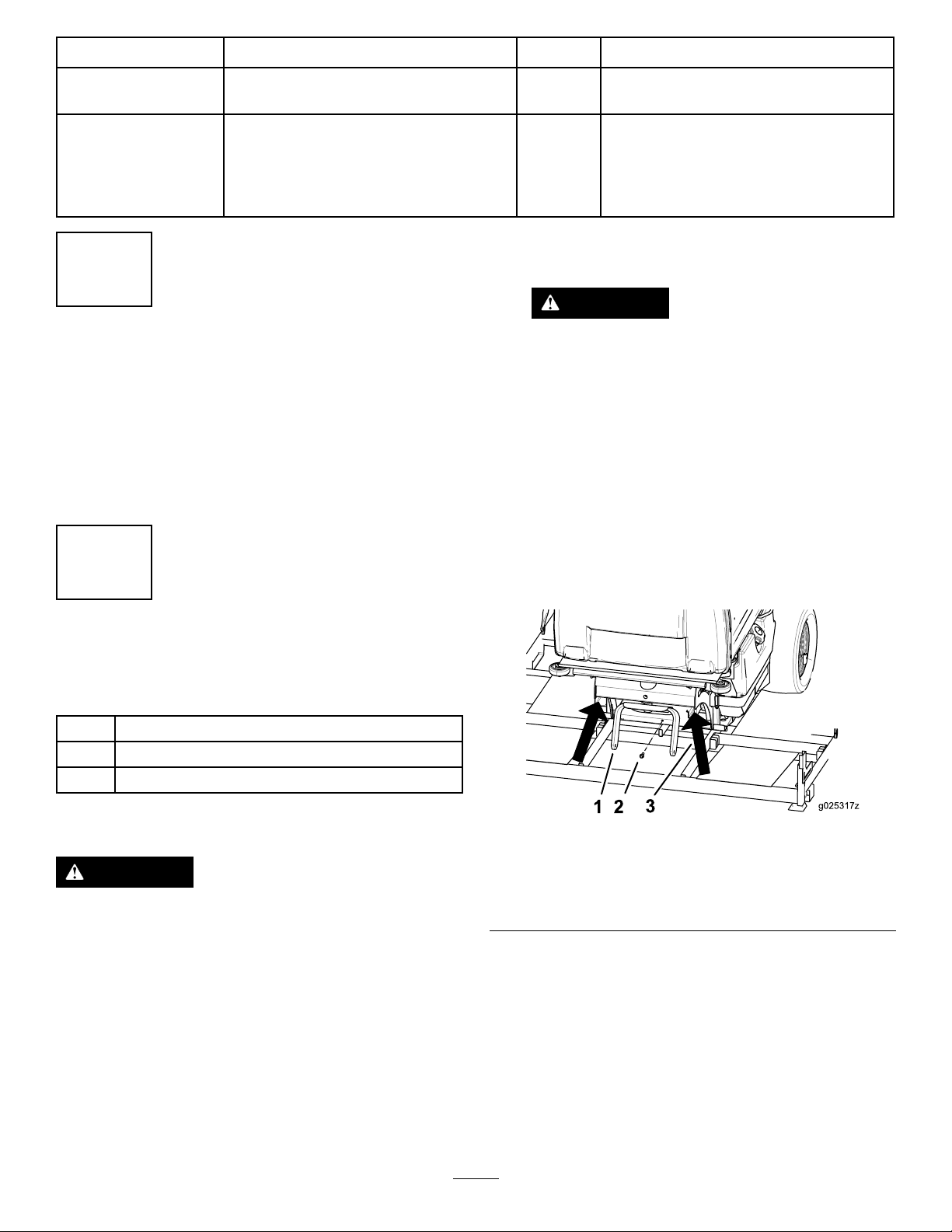
3.Raisetherearoftheunitapproximately25.4to30.5
cm(10to12inches)andsupportitwithjackstandsor
equivalentsupport(Figure1).
Figure1
1.Rearcasterfork
2.Boltholdingtherear-frame
support
4.Removeanddiscardtherear-framesupport,located
behindthedrivetires,fromthemachine.
5.Installtherearcasterwheeltotherearcasterforkwith
abolt(1/2x13inches)andlocknut(1/2inch)(Figure
2).
3.Placethejackstandsat
thearrows
Note:Ensurethedischargetubedoesnotcatchonthecrate
whendrivingthemachineoffthecrate(Figure4).
1.Removetherearcasterwheelassemblyfrominside
thehopper.
6.Torquetheboltto90.8to112.5N-m(67to83ft-lb).
2
Page 3
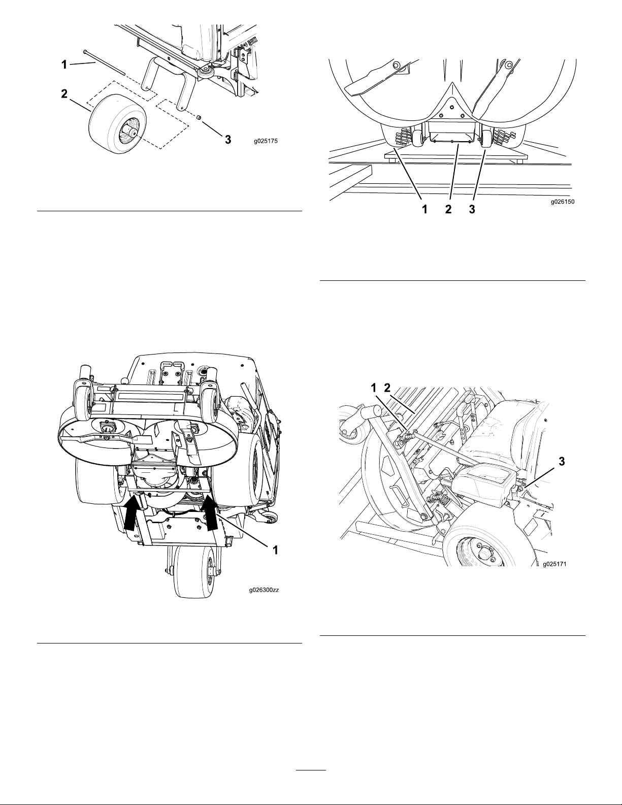
Figure2
1 2 3
g026150
1.Bolt(1/2x13inches)3.Locknut(1/2inch)
2.Rearcasterwheel
providesupportforthedeckwhentheunitisdriven
offofthecrate(Figure4).
7.Carefullyremovethejackstandsandlowerthemachine.
Important:Ensurethemowerdeckisinthe
uprightpositionbeforeraisingthefrontofthe
machine.
8.Raisethefrontofthemachineandsupportitwithjack
standsoranequivalentsupport(Figure3).
Note:Liftthedeckjustenoughtoremovethedeck
supportandtoinsertothersupportsintothecrate
opening.
Figure4
1.Drivetire3.Plywoodsheetunderthe
reardeckrollers
2.Dischargetube
11.Carefullyremovethejackstandsandlowerthemachine.
12.Whilesupportingthemowerdeck,removeanddiscard
thetwosidestruts,mountingbrackets,andtheir
hardwareonbothsidesoftheseat(Figure5).
13.Removeanddiscardthestrutlocatedbetweenthefront
decksupportpins(Figure5).
Figure3
1.Placejackstandsatthearrows
9.Removeanddiscardthedecksupportfromunderthe
reardeckrollers.
Note:Beforethedeckisloweredintotheoperating
position(steps10through14),thecrateopeningunder
thedeckmustbefullycovered.
10.Placeaplywoodsheet(58.4cmx81.3cm(23inches
x32inches)),orsimilarsupport,overtheopeningto
Figure5
1.Decksupportpin
2.Strutbetweendeck
supportpins
3.Sidestruthardware
14.Withthedecklockingpinspulledoutintheunlock
position,carefullylowerthedeck(Figure6).
3
Page 4
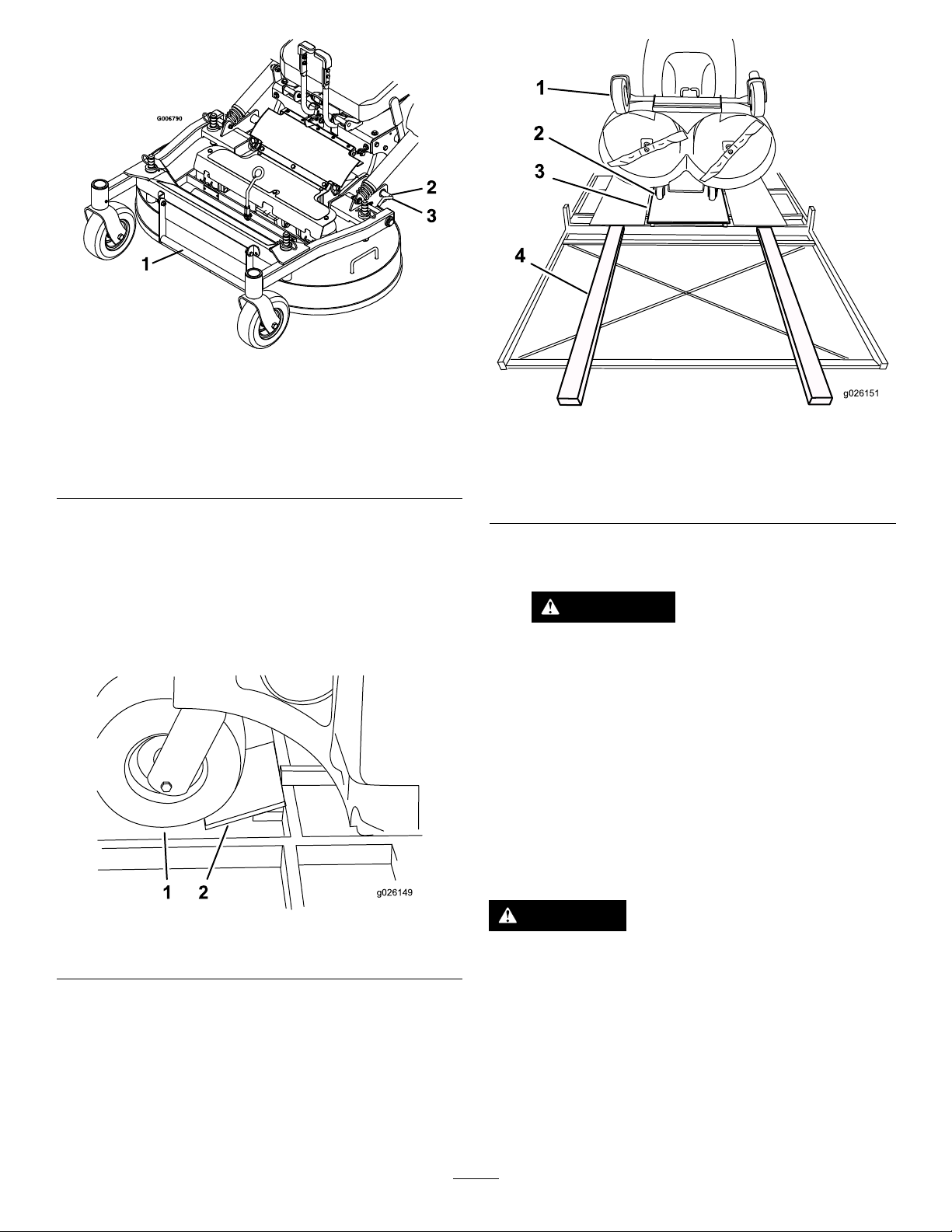
Figure6
1 2
g026149
g026151
1
2
3
4
1.Decklifthandle
2.Rotatethedecklocking
pintowardtherearand
pulloutwardtounlock
3.Pushthedecklockingpin
inandrotatetowardthe
fronttolock
15.Pushthedeck-lockingpinsinwardandrotatethem
forwardtosecurelylockthedeckinthelowered
position.
16.Raisethemowerdecktothehighestheight-of-cut
position.
17.Installpiecesofwood,toformaramp,infrontofthe
reartire(Figure7).
Figure8
1.Frontcaster3.Plywoodbetweendrive
2.Reardeckrollers
wheels
4.Woodrampforfront
casters(2x4’s)
Note:Ensurethedischargetubedoesnotcatchonthe
cratewhendrivingthemachineoffthecrate(Figure4).
WARNING
Operatingmowerwithoutlockingpins
securelylatchedcanresultinthemowerdeck
foldingupunexpectedly.Themowerdeck
foldingupunexpectedlycancauseserious
injury.
Alwaysoperatemowerwithlockingpins
securelylatched.
19.Drivethemachineoffthecrate.
1.Reartire2.Woodramp
18.Toformaramp,place2longpiecesofwood(2x4’s)
Figure7
infrontofeachfront-castertire(Figure8).
RemovingtheMachinefromtheCrate
UsingaHoist
CAUTION
ThemowerdeckisshippedintheUpposition,but
notlatched.Removingshippingreinforcements
withoutsupportingthefrontofthedeckwillcause
thedecktodropwhichmayresultininjuryor
propertydamage.
Alwayssecurelysupportthefrontofthedeckwhile
settinguptheunit.
1.Removetherearcasterwheelassemblyfrominside
thehopper.
4
Page 5

2.Removetheboltholdingtherearframetothecrate
(Figure11).
3.Liftthefrontofthehopperup.
Note:Usecarewhenhoistingthemachinetoprevent
damagetothehopper.
4.Usingthehoist,liftthemachineatthelocationshown
inFigure9.
Figure10
Figure9
1.Withthehopperup,liftthemachineoneachsidehere
CAUTION
Raisingthemowerdeckforserviceor
maintenancerelyingsolelyonmechanical
orhydraulicjackscouldbedangerous.The
mechanicalorhydraulicjacksmaynotbe
enoughsupportormaymalfunctionallowing
theunittofall,whichcouldcauseinjury.
DoNotrelysolelyonmechanicalorhydraulic
jacksforsupport.Useadequatejackstands
orequivalentsupport.
5.Raisetherearoftheunitapproximately25.4to30.5
cm(10to12inches)andsupportitwithjackstandsor
equivalentsupport(Figure10).
1.Rearcasterfork
2.Boltholdingrearframe
3.Placejackstandsatthe
arrows
6.Removeanddiscardtherear-framesupportandits
hardware,locatedbehindthedrivetires.
7.Installtherearcasterwheeltotherearcasterforkwith
abolt(1/2x13inches)andlocknut(1/2inch)(Figure
11).
8.Torquetheboltto90.8to112.5N-m(67to83ft-lb).
Figure11
1.Bolt(1/2x13inches)3.Locknut(1/2inch)
2.Rearcasterwheel
9.Carefullyremovethejackstandsandlowerthemachine.
10.Lowerthefrontofthehopper.
11.Tilttheseatup.
12.Placethehoisthooksoneachsideoftheseatasshown
inFigure12.
5
Page 6

Figure12
1.Liftpointsoneachsideoftheseat
1.Decksupportpin
2.Strutbetweenthe
deck-supportpins
Figure13
3.Side-struthardware
Important:Ensurethemowerdeckisinthe
uprightpositionbeforeraisingthefrontofthe
machine.
13.Raiseupthefrontofthemachine,justenoughto
removeanddiscardthedecksupportfromunderthe
reardeckrollers.
14.Lowerthemachinetotheground.
15.Liftthefrontofthehopperup.
16.Usingthehoist,liftthemachineatthelocationsshown
inFigure9andFigure12.
17.Removethecratefromunderthemachine.
18.Lowerthemachinetotheground.
19.Whilesupportingthemowerdeck,removeanddiscard
thetwosidestruts,mountingbrackets,andtheir
hardwareonbothsidesoftheseat(Figure13).
20.Removeanddiscardthestrutlocatedbetweenthefront
decksupportpins(Figure13).
21.Withthedecklockingpinspulledoutintheunlock
position,carefullylowerthedeck(Figure14).
Figure14
1.Decklifthandle
2.Rotatethedecklocking
pintowardtherearand
pulloutwardtounlock
3.Pushthedecklockingpin
inandrotatetowardthe
fronttolock
22.Pushthedecklockingpinsinwardandrotatethem
forwardtosecurelylockthedeckinthelowered
position.
6
Page 7

WARNING
Operatingmowerwithoutlockingpins
securelylatchedcanresultinthemowerdeck
foldingupunexpectedly.Themowerdeck
foldingupunexpectedlycancauseserious
injury.
Alwaysoperatemowerwithlockingpins
securelylatched.
6
InstallingtheBattery
Partsneededforthisprocedure:
2
Wingnut(1/4inch)
Procedure
3
CheckingtheTirePressure
NoPartsRequired
Procedure
Pressure:103kPa(15psi)
Note:Checkthetirepressurebeforestartingthemachine.
RefertoyourOperator’sManualforthecorrecttiretype,
correctairpressureneeded,andprocedure.
4
CheckingtheEngine-OilLevel
NoPartsRequired
Procedure
Beforeyoustarttheengineandusethemachine,check
theoillevelintheenginecrankcase;refertoServicingthe
Engine-OilLevelintheOperator'sManual.
WARNING
CALIFORNIA
Proposition65Warning
Batteryposts,terminals,andrelated
accessoriescontainleadandleadcompounds,
chemicalsknowntotheStateofCalifornia
tocausecancerandreproductiveharm.
Washhandsafterhandling .
CAUTION
Batteryelectrolytecontainssulfuricacid,whichis
poisonousandcancausesevereburns.Swallowing
electrolytecanbefatalorifittouchesskincan
causesevereburns.
•Wearsafetyglassestoshieldeyes,andrubber
glovestoprotectskinandclothingwhen
handlingelectrolyte.
•DoNotswallowelectrolyte.
•Intheeventofanaccident,ushwithwaterand
calladoctorimmediately.
WARNING
5
CheckingtheWheelLugNut
Torque
NoPartsRequired
Procedure
Beforeyoustarttheengineandusethemachine,checkthe
wheellugnuttorque;refertoCheckingtheWheelLugNuts
intheOperator'sManual
IftheignitionisintheOnpositionthereispotential
forsparksandengagementofcomponents.Sparks
couldcauseanexplosionormovingpartscould
accidentallyengagecausingpersonalinjury.
BesureignitionswitchisintheOffpositionbefore
chargingthebattery.
Locatethebattery-mountinghardwareandinstallthenegative
batterycable.RefertoInstallingtheBatteryintheOperator's
Manual.
Note:Ifthepositivecableisalsodisconnected,connectthe
positive(red)cabletothepositivebatteryterminalrst,then
thenegative(black)cabletothenegativebatteryterminal.
Slipinsulatorbootoverthepositiveterminal.
7
Page 8

Note:Iftimedoesnotpermitchargingthebattery,orif
chargingequipmentisnotavailable,connectthenegative
batterycableandrunthevehiclecontinuouslyfor20to30
minutestosufcientlychargethebattery.
8
CheckingtheHydraulicOil
7
ChargingtheBattery
NoPartsRequired
Procedure
WARNING
Chargingthebatteryproducesgassesthatcan
explodeandcauseseriousinjury.
•Keepcigarettes,sparksandamesawayfrom
thebattery.
•Makesuretheignitionswitchisoff.
•Ventilatewhenchargingorusingthebatteryin
anenclosedspace.
Important:Donotrunthemachinewiththebattery
disconnected;electricaldamagemayoccurtothe
engine.
Chargethebattery.RefertotheOperator'sManualfor
instructions.
NoPartsRequired
Procedure
Themachineisshippedwithhydraulicoilinthereservoir.
1.Checkandensurethereservoirhashydraulicoil.
2.IfneededaddToroHYPR-OIL™500hydraulicoil.
3.Runthemachineforapproximately15minutestoallow
anyextraairtopurgeoutofthehydraulicsystem.
4.Waituntiltheunitcoolsbeforecheckingthehydraulic
oil.
5.Tiltthehopperup.
6.Removethehydraulicreservoircap.
7.Wipethedipstickcleanandinsertthecapbackinto
thehydro.
8.Lightlytightenthecap.
9.Removethecapagainandchecktheleveloftheoil
onthedipstick(Figure16).
10.Checkthehydraulicreservoirandifnecessaryll
thereservoirtotheappropriatelevelwithToro
HYPR-OIL™500hydraulicoil.
Figure15
Figure16
1.Full2.Add
11.IfthedipstickoillevelisattheAddmark,addhydraulic
oil.Donotoverll.
12.Replacehydraulicreservoircapandtightenuntilsnug.
Donotovertighten.
8
Page 9

9
CheckingtheMachinefor
Grease
Partsneededforthisprocedure:
1tube
Procedure
Beforeyouusethemachine,checkthemachineforgrease;
refertoLubricationintheOperator'sManual.
Number2general-purposelithium-baseor
molybdenum-basegrease.(Purchaseseparately.)
9
Page 10

10
CheckingtheMachineBeforeDeliverytotheCustomer
NoPartsRequired
Procedure
Beforedeliveringthemachinetothecustomer,ensurethatyouperformorhaveperformedtheprocedureslistedinthe
followingtableandinitialeachwhennished.RefertotheOperator'sManualforinstructionsonperformingtheseprocedures.
Initial
Checkthetirepressure.
Checkthelevelofthemachine.
Checkthemowerdeckgearboxesforoil.
Checktheengine-oillevel.
Checkthehydraulic-uidlevel.
Checktheadjustmentoftheparkingbrake.
Ensurethatthemachinetrackscorrectly;refertotheOperator'sManualfortheadjustmentprocedure.
Checkthesafetyinterlocksystem;refertotheOperator'sManual.
EnsurethatthePTOworks.
Checkallfastenersthatyouinstalledtoensurethattheyaretight.
Whenyounishsettingupthemachine,signanddateinthespaceprovidedbelow:
Signature:
CheckProcedure
Date:
10
Page 11

11
DeliveringtheMachinetotheCustomer
Partsneededforthisprocedure:
1
Operator'sManual
1
EngineOwner'sManual
1Registrationcard
1
Operator-trainingmaterial
2Key
Procedure
Atdelivery,llinthemodelandserialnumber,completetheitemslistedinthefollowingtable,andinitialeachwhennished.
ModelNo.
SerialNo.
11
Page 12

DealerInitial
CustomerInitialCheckProcedure
Showthecustomerwherethefollowingfeaturesarelocatedandhowtheyfunction:
•
Fueltank
•
Oilllcap/Oildipstick
•
Sparkplug(s)
•
Engine-oillter
•
Engine-oildrain
•
Fuelgauge,valveandhose
•
Airlter
•
Hydraulic-uidreservoir
•
Hydrauliclter
•
Battery
•
Ignitionswitch
•
Throttlelever
•
Choke(ifapplicable)
•
Powertakeoff(PTO)
•
Motion-controllevers
•
Parkingbrake
•
Height-of-cut
•
Adjustableseat
•
Hydraulic-bypassvalves
•
Mowerdeckbafe
RefertotheOperator'sManualtopointoutsafetyprocedures,operation,and
maintenanceprocedures.
ReviewthewarrantystatementasshownintheOperator'sManual.
Describethepostsaleserviceproceduresforyourstore.
Assistthecustomerinllingoutandmailingtheregistrationcardorregisteronlineat
www.T oro.com
MakesurethatthecustomerreceivestheOperator'sManual,EngineOwner'sManual,
SetUpInstructions,andoperatortrainingmaterial.
MakesurethecustomerknowsthePartsCatalogisavailableatwww.T oro.com.
Assistthecustomerinloadingthemachine.
Note:Whenyou,thedealerrepresentative,havenisheddeliveringthemachinetothecustomer,signanddateinthespace
providebelowandkeepacopyofthispagefordealerrecords.Also,thedealermustremindthecustomertouseafull-width
trailerramptoloadthemachine.
Signature:
Signature:Date:
Date:
12
 Loading...