

Page 1

Consumer Products
TimeCutter® Z / Precision® Z
Zero Radius Turn Riding Mower
Service Manual
Page 2

ABOUT THIS MANUAL
This service manual was written expressly for Toro and Lawn-Boy service technicians. The Toro
Company has made every effort to make the information in this manual complete and correct.
Basic shop safety knowledge and mechanical/electrical skills are assumed. The Table of
Contents lists the systems and the related topics covered in this manual.
For additional information on the electrical system, please refer to the Toro Electrical
Demystifi cation Guide (492-4761) and subsequent. For service information on drive systems,
please refer to the Hydro-Gear EZT service manual (492-4778). For information specifi c to the
engines used on this unit, refer to the appropriate engine manufacturer’s service and repair
instructions.
Toro TimeCutter
are covered in this manual. The manual may also be specifi ed for use on later model products.
The hydrostatic transaxle is a sophisticated piece of machinery. Maintain strict cleanliness
control during all stages of service and repair. Cover or cap all hose ends and fi ttings whenever
they are exposed. Even a small amount of dirt or other contamination can severely damage the
system.
We are hopeful that you will fi nd this manual a valuable addition to your service shop. If you
have any questions or comments regarding this manual, please contact us at the following
address:
The Toro Company
Consumer Service Training Department
8111 Lyndale Avenue South
Bloomington, MN 55420
The Toro Company reserves the right to change product specifi cations or this manual without
notice.
®
Z model year 2003 - 2006 and Lawn-Boy Precision® Z model year 2005 - 2006
Copyright© All Rights Reserved
©2007 The Toro Company
Page 3

TABLE OF CONTENTS
SAFETY INFORMATION
General Information . . . . . . . . . . . . . . . . . . . . . . . . . . . . . . . . . .
Think Safety First . . . . . . . . . . . . . . . . . . . . . . . . . . . . . . . . . . .
A1-2
A1-2
SPECIFICATIONS
General Specifi cations Toro TimeCutter
General Specifi cations Lawn-Boy Precision® Z . . . . . . . . . . . . . . . . . . . . . . .
Hydrostatic Transaxles . . . . . . . . . . . . . . . . . . . . . . . . . . . . . . . .
Transaxle Specifi cations . . . . . . . . . . . . . . . . . . . . . . . . . . . . . . . .
Hydrostatic Transaxles cont. . . . . . . . . . . . . . . . . . . . . . . . . . . . . . .
Torque Specifi cations . . . . . . . . . . . . . . . . . . . . . . . . . . . . . . . . .
Standard Torque for Dry, Zinc Plated, and Steel Fasteners (Inch Series) . . . . . . . . . . . . .
Standard Torque for Dry, Zinc, and Steel Fasteners (Metric Fasteners) . . . . . . . . . . . . . .
Other Torque Specifi cations . . . . . . . . . . . . . . . . . . . . . . . . . . . . . . .
Equivalents and Conversions . . . . . . . . . . . . . . . . . . . . . . . . . . . . . .
U.S. to Metric Conversions . . . . . . . . . . . . . . . . . . . . . . . . . . . . . . .
CHASSIS
Model and Serial Number Location . . . . . . . . . . . . . . . . . . . . . . . . . . . .
Engine Model and Serial Number Identifi cation . . . . . . . . . . . . . . . . . . . . . . .
Greasing and Lubrication . . . . . . . . . . . . . . . . . . . . . . . . . . . . . . . .
Front Castor Fork Removal and Installation . . . . . . . . . . . . . . . . . . . . . . . .
Removal . . . . . . . . . . . . . . . . . . . . . . . . . . . . . . . . . . . .
Installation . . . . . . . . . . . . . . . . . . . . . . . . . . . . . . . . . . . .
Castor Support Removal . . . . . . . . . . . . . . . . . . . . . . . . . . . . . . . .
Installation . . . . . . . . . . . . . . . . . . . . . . . . . . . . . . . . . . . .
Side Panel Removal . . . . . . . . . . . . . . . . . . . . . . . . . . . . . . . . .
Left Side Panel Removal . . . . . . . . . . . . . . . . . . . . . . . . . . . . . .
Installation . . . . . . . . . . . . . . . . . . . . . . . . . . . . . . . . . . . .
Right Side Panel and Gas Tank Removal . . . . . . . . . . . . . . . . . . . . . . . . .
Installation . . . . . . . . . . . . . . . . . . . . . . . . . . . . . . . . . . . .
Lift Arm Assembly . . . . . . . . . . . . . . . . . . . . . . . . . . . . . . . . . .
Removal . . . . . . . . . . . . . . . . . . . . . . . . . . . . . . . . . . . .
Installation . . . . . . . . . . . . . . . . . . . . . . . . . . . . . . . . . . . .
Belt Replacement . . . . . . . . . . . . . . . . . . . . . . . . . . . . . . . . . .
Removal . . . . . . . . . . . . . . . . . . . . . . . . . . . . . . . . . . . .
Belt Installation . . . . . . . . . . . . . . . . . . . . . . . . . . . . . . . . . . .
®
Z . . . . . . . . . . . . . . . . . . . . . . . . .
A2-2
A2-4
A2-6
A2-5
A2-7
A2-8
A2-9
A2-10
A2-11
A2-12
A2-13
3-2
3-2
3-2
3-3
3-3
3-3
3-3
3-4
3-4
3-4
3-4
3-5
3-6
3-6
3-6
3-6
3-7
3-7
3-8
HYDRO-GEAR TRANSAXLE
Hydro-Gear (310-2200) EZT™ Transaxles . . . . . . . . . . . . . . . . . . . . . . . . .
Internal Service . . . . . . . . . . . . . . . . . . . . . . . . . . . . . . . . . .
Fluid Change . . . . . . . . . . . . . . . . . . . . . . . . . . . . . . . . . .
Transaxle Removal . . . . . . . . . . . . . . . . . . . . . . . . . . . . . . . .
Removing Transaxles from the Hydro Mount Frame . . . . . . . . . . . . . . . . . . . . .
Assembly . . . . . . . . . . . . . . . . . . . . . . . . . . . . . . . . . . . .
Wheel Hub Removal . . . . . . . . . . . . . . . . . . . . . . . . . . . . . . . . .
Installation Wheel Hub . . . . . . . . . . . . . . . . . . . . . . . . . . . . . . .
Transaxle Installation . . . . . . . . . . . . . . . . . . . . . . . . . . . . . . . . .
Purging Procedures - Hydro-Gear Transaxles . . . . . . . . . . . . . . . . . . . . . . . .
Neutral Adjustment . . . . . . . . . . . . . . . . . . . . . . . . . . . . . . . . . .
Tracking Adjustments . . . . . . . . . . . . . . . . . . . . . . . . . . . . . . . . .
Brake Adjustment . . . . . . . . . . . . . . . . . . . . . . . . . . . . . . . . . .
Actuator Arm Removal . . . . . . . . . . . . . . . . . . . . . . . . . . . . . . . . .
4-2
4-2
4-2
4-2
4-4
4-5
4-5
4-5
4-6
4-8
4-9
4-11
4-11
4-12
iTimeCutter Z / Precision Z Service Manual
Page 4

TABLE OF CONTENTS
HYDRO-GEAR TRANSAXLE cont.
Actuator Arm Installation . . . . . . . . . . . . . . . . . . . . . . . . . . . . . . . .
310-2200 EZT™ Troubleshooting Checklist . . . . . . . . . . . . . . . . . . . . . . . .
ELECTRICAL SYSTEM
Electrical System . . . . . . . . . . . . . . . . . . . . . . . . . . . . . . . . . . .
Relay (Kill Relay) . . . . . . . . . . . . . . . . . . . . . . . . . . . . . . . . . . .
Purpose . . . . . . . . . . . . . . . . . . . . . . . . . . . . . . . . . . . . .
Location . . . . . . . . . . . . . . . . . . . . . . . . . . . . . . . . . . . . .
How It Works . . . . . . . . . . . . . . . . . . . . . . . . . . . . . . . . . . .
Testing . . . . . . . . . . . . . . . . . . . . . . . . . . . . . . . . . . . . .
Solenoid . . . . . . . . . . . . . . . . . . . . . . . . . . . . . . . . . . . . . .
Purpose . . . . . . . . . . . . . . . . . . . . . . . . . . . . . . . . . . . . .
Location . . . . . . . . . . . . . . . . . . . . . . . . . . . . . . . . . . . . .
How It Works . . . . . . . . . . . . . . . . . . . . . . . . . . . . . . . . . . .
Testing . . . . . . . . . . . . . . . . . . . . . . . . . . . . . . . . . . . . .
Ignition Switch . . . . . . . . . . . . . . . . . . . . . . . . . . . . . . . . . . . .
Purpose . . . . . . . . . . . . . . . . . . . . . . . . . . . . . . . . . . . . .
Location . . . . . . . . . . . . . . . . . . . . . . . . . . . . . . . . . . . . .
How It Works . . . . . . . . . . . . . . . . . . . . . . . . . . . . . . . . . . .
Testing . . . . . . . . . . . . . . . . . . . . . . . . . . . . . . . . . . . . .
PTO Switch . . . . . . . . . . . . . . . . . . . . . . . . . . . . . . . . . . . . .
Purpose . . . . . . . . . . . . . . . . . . . . . . . . . . . . . . . . . . . . .
Location . . . . . . . . . . . . . . . . . . . . . . . . . . . . . . . . . . . . .
How It Works . . . . . . . . . . . . . . . . . . . . . . . . . . . . . . . . . . .
Testing . . . . . . . . . . . . . . . . . . . . . . . . . . . . . . . . . . . . .
Electric PTO Clutch . . . . . . . . . . . . . . . . . . . . . . . . . . . . . . . . . .
Purpose . . . . . . . . . . . . . . . . . . . . . . . . . . . . . . . . . . . . .
Location . . . . . . . . . . . . . . . . . . . . . . . . . . . . . . . . . . . . .
How It Works . . . . . . . . . . . . . . . . . . . . . . . . . . . . . . . . . . .
Testing . . . . . . . . . . . . . . . . . . . . . . . . . . . . . . . . . . . . .
Coil Resistance Measurement . . . . . . . . . . . . . . . . . . . . . . . . . . . .
Measuring Clutch Current Draw . . . . . . . . . . . . . . . . . . . . . . . . . . .
Park Brake Switch . . . . . . . . . . . . . . . . . . . . . . . . . . . . . . . . . .
Purpose . . . . . . . . . . . . . . . . . . . . . . . . . . . . . . . . . . . . .
Location . . . . . . . . . . . . . . . . . . . . . . . . . . . . . . . . . . . . .
How It Works . . . . . . . . . . . . . . . . . . . . . . . . . . . . . . . . . . .
Testing . . . . . . . . . . . . . . . . . . . . . . . . . . . . . . . . . . . . .
Seat Switch . . . . . . . . . . . . . . . . . . . . . . . . . . . . . . . . . . . . .
Purpose . . . . . . . . . . . . . . . . . . . . . . . . . . . . . . . . . . . . .
Location . . . . . . . . . . . . . . . . . . . . . . . . . . . . . . . . . . . . .
How It Works . . . . . . . . . . . . . . . . . . . . . . . . . . . . . . . . . . .
Testing . . . . . . . . . . . . . . . . . . . . . . . . . . . . . . . . . . . . .
4-14
4-16
5-2
5-2
5-2
5-2
5-2
5-2
5-3
5-3
5-3
5-3
5-3
5-4
5-4
5-4
5-4
5-4
5-5
5-5
5-5
5-5
5-5
5-7
5-7
5-7
5-7
5-7
5-7
5-7
5-8
5-8
5-8
5-8
5-9
5-9
5-9
5-9
5-9
5-9
MOWER DECKS - 38”/42”, 44” AND 48” DECK ASSEMBLIES
38”/42” Mower Decks
Leveling the Mower from Side-to-Side . . . . . . . . . . . . . . . . . . . . . . . . .
Adjusting the Front-to-Rear Blade Slope . . . . . . . . . . . . . . . . . . . . . . . .
Inspecting the Belts . . . . . . . . . . . . . . . . . . . . . . . . . . . . . . . .
Replacing the Mower Belt . . . . . . . . . . . . . . . . . . . . . . . . . . . . . .
Removing the Mower . . . . . . . . . . . . . . . . . . . . . . . . . . . . . . .
Installing the Mower . . . . . . . . . . . . . . . . . . . . . . . . . . . . . . . .
ii TimeCutter Z / Precision Z Service Manual
6-2
6-3
6-4
6-4
6-6
6-7
Page 5

TABLE OF CONTENTS
MOWER DECKS - 38”/42”, 44” AND 48” DECK ASSEMBLIES cont.
44” Mower Decks
Leveling the Mower from Side-to-Side . . . . . . . . . . . . . . . . . . . . . . . . .
Adjusting the Front-to-Rear Blade Slope . . . . . . . . . . . . . . . . . . . . . . . .
Inspecting the Belts . . . . . . . . . . . . . . . . . . . . . . . . . . . . . . . .
Replacing the Mower Belt . . . . . . . . . . . . . . . . . . . . . . . . . . . . . .
Removing the Mower . . . . . . . . . . . . . . . . . . . . . . . . . . . . . . .
Installing the Mower . . . . . . . . . . . . . . . . . . . . . . . . . . . . . . . .
48” Mower Decks
Leveling the Mower from Side-to-Side . . . . . . . . . . . . . . . . . . . . . . . . .
Adjusting the Front-to-Rear Blade Slope . . . . . . . . . . . . . . . . . . . . . . . .
Removing the Mower . . . . . . . . . . . . . . . . . . . . . . . . . . . . . . .
Mower Belt Maintenance . . . . . . . . . . . . . . . . . . . . . . . . . . . . . .
Installing the Mower . . . . . . . . . . . . . . . . . . . . . . . . . . . . . . . .
6-8
6-8
6-10
6-10
6-11
6-12
A6-13
A6-14
A6-16
A6-17
A6-18
iiiTimeCutter Z / Precision Z Service Manual
Page 6

TABLE OF CONTENTS
THIS PAGE INTENTIONALLY LEFT BLANK.
iv TimeCutter Z / Precision Z Service Manual
Page 7

SAFETY INFORMATION
TIMECUTTER® Z / PRECISION® Z SERVICE MANUAL
Safety Information . . . . . . . . . . . . . . . . . . . . . . . . .
Specifi cations . . . . . . . . . . . . . . . . . . . . . . . . . . . .
Chassis . . . . . . . . . . . . . . . . . . . . . . . . . . . . . . .
Hydro-Gear
Transaxle . . . . . . . . . . . . . . . . . . . . . . . .
1
1
2
2
3
3
4
4
Electrical Systems . . . . . . . . . . . . . . . . . . . . . . . . . .
Mower Decks . . . . . . . . . . . . . . . . . . . . . . . . . . . .
5
5
6
6
A1-1TimeCutter Z / Precision Z Service Manual
Page 8

SAFETY INFORMATION
General Information
This symbol means WARNING or
PERSONAL SAFETY INSTRUCTION
1
This manual is intended as a service and repair
manual only. The safety instructions provided herein
are for troubleshooting, service, and repair of the
TimeCutter
Z®. The TimeCutter® Z zero radius tractor and the
Think Safety First
- read the instruction because it has to
do with your safety. Failure to comply
with the instruction may result in
personal injury or even death.
Z zero radius tractor and the Precision
Precision Z® attachment operator’s manuals contain
safety information and operating tips for safe operating
practices. Operator’s manuals are available through
your Toro parts source or:
The Toro Company
Publications Department
8111 Lyndale Avenue South
Bloomington, MN 55420
Avoid unexpected starting of engine...
Always turn off the engine and disconnect the spark
plug wire(s) before cleaning, adjusting, or repair.
Avoid lacerations and amputations...
Stay clear of all moving parts whenever the engine is
running. Treat all normally moving parts as if they were
moving whenever the engine is running or has the
potential to start.
Avoid burns...
Do not touch the engine, muffler, or other components
which may increase in temperature during operation,
while the unit is running or shortly after it has been
running.
Avoid fires and explosions...
Avoid spilling fuel and never smoke while working with
any type of fuel or lubricant. Wipe up any spilled fuel or
oil immediately. Never remove the fuel cap or add fuel
when the engine is running. Always use approved,
labeled containers for storing or transporting fuel and
lubricants.
Avoid injury from batteries...
Battery acid is poisonous and can cause burns. Avoid
contact with skin, eyes, and clothing. Battery gases
can explode. Keep cigarettes, sparks, and flames away
from the battery.
Avoid injury due to inferior parts...
Use only original equipment parts to ensure that
important safety criteria are met.
Avoid injury to bystanders...
Always clear the area of bystanders before starting or
testing powered equipment.
Avoid injury due to projectiles...
Always clear the area of sticks, rocks, or any other
debris that could be picked up and thrown by the
powered equipment.
Avoid modifications...
Never alter or modify any part unless it is a factory
approved procedure.
Avoid asphyxiation...
Never operate an engine in a confined area without
proper ventilation.
A1-2 TimeCutter Z / Precision Z Service Manual
Avoid unsafe operation...
Always test the safety interlock system after making
adjustments or repairs on the machine. Refer to the
Electrical section in this manual for more information.
Page 9

SPECIFICATIONS
TIMECUTTER® Z / PRECISION® Z SERVICE MANUAL
Safety Information . . . . . . . . . . . . . . . . . . . . . . . . . .
Specifi
Chassis . . . . . . . . . . . . . . . . . . . . . . . . . . . . . . .
Hydro-Gear Transaxle . . . . . . . . . . . . . . . . . . . . . . . .
cations . . . . . . . . . . . . . . . . . . . . . . . . . . .
1
1
2
2
3
3
4
4
Electrical Systems . . . . . . . . . . . . . . . . . . . . . . . . . .
Mower Decks . . . . . . . . . . . . . . . . . . . . . . . . . . . .
5
5
6
6
A2-1TimeCutter Z / Precision Z Service Manual
Page 10

SPECIFICATIONS
General Specifi cations - Toro TimeCutter® Z
Item Specifi cation
Engines All units were manufactured with Briggs & Stratton engines ranging from 14 to 17
horsepower. For information on servicing the engine, contact Briggs & Stratton
Corporation.
RPM setting,
all models
2
Construction Frame: 10 gauge steel
Fuel Capacity 2 gallons (7.5 liters) Diesel Fuel
Wheel Base 47.6” (120.9cm) center of front to center of drive tires
Overall Length 72.6” (184.4cm)
Overall Width Model Width
High RPM Setting (no load) 3300 + 100 RPM
14-38Z & Z380 45.4” (115.3cm) with deck defl ector down, 42.4” (107.7cm) Gate
width with defl ector up.
16-42Z, 17-42Z &
Z420
18-44Z 60” (152.4cm) with deck defl ector down, 46.6” (118.4cm) Gate
Z480 62.5” (158.8cm) with deck defl ector down, 53.5” (135.9cm) Gate
Weight Model Net Weight Model Net Weight
14-38Z & Z380 505 lbs. (229kg) est. 18-44Z 535 lbs. (243kg) est.
16-42Z & Z420 516 lbs. (234kg) est. Z480 550 lbs. (249kg) est.
17-42Z 516 lbs. (234kg) est.
Traction System Transaxles: Twin Hydro-Gear EZT
Transaxle Drive: Belt Drive with self-tensioning system.
Ground Speed Forward: Infi nite 0 – 6.0 mph (9.6km/hr)
Reverse: Infi nite 0 – 3 mph (5km/hr)
Tires Front Tires all models - 410/350 x 4-4.25
Rear Tires 18 x 6.5 - 8, 14-38Z/Z380
Rear Tires 18 x 7.5 - 8, 16-42Z/Z420
Rear Tires 18 x 8.5 - 8, 17-42Z/18-44Z/Z480
Tire Pressure Front Tires 35 psi (241kPa)
Rear Tires 13 psi (90kPa)
Attachment Drive Electric Clutch, Maintenance Free, No Adjustments
50.7” (128cm) with deck defl ector down, 45.0” (116.8cm) Gate
width with defl ector up.
width with deck defl ector up.
width with deck defl ector up.
A2-2 TimeCutter Z / Precision Z Service Manual
Page 11

SPECIFICATIONS
Item Specifi cation
Mower Decks 38” (97cm) cut, right side discharge, two blade mid-mount rotary. Drawn 13 gauge steel
deck with welded mounting brackets. Frame supported
42” (107cm) right side discharge, two blade mid-mount rotary. Drawn 13 gauge steel
deck with welded mounting brackets. Frame supported.
44” (112cm) cut, right side discharge, three blade mid-mount rotary. Drawn 13 gauge
steel deck with welded mounting brackets. Frame supported.
48” (121.8cm) cut, right side discharge, three blade mid-mount rotary. Drawn 13 gauge
steel deck with welded mounting brackets. Frame supported.
Blade Tip Speed Model Speed
14-38Z & Z380 16,760 ft/min @ 3300 RPM nominal, 17,270 ft/min @ 3400 RPM
max.
16-42Z & 17-42Z &
Z420
18-44Z 17,310 ft/min @ 2700 RPM
Z480 15,230 ft/min @3300 RPM nominal, 15,710 ft/min @ 3400 RPM
14-38Z (Int’l model) 13,710 ft/min @ 2700 RPM
16-42Z (Int’l model) 14,140 ft/min @ 2700 RPM
Height-of-Cut All models except Z480 - Seven height-of-cut positions from 1.5” (38mm) to 4.5
(114mm), 1/2” (12.7mm) increments.
Z480 - Seven height-of-cut positions from 1.0” (25.4mm) to 4.0 (101.6mm), 1/2”
(12.7mm) increments.
Electrical System Battery Voltage: 12 volt negative ground
Battery Type: BCI Group U1
17,290 ft/min @ 3300 RPM nominal, 17,810 ft/min @ 3400 RPM
max.
max.
2
A2-3TimeCutter Z / Precision Z Service Manual
Page 12

SPECIFICATIONS
General Specifi cations - Lawn-Boy Precision Z
Item Specifi cation
Engines Units were manufactured with Briggs & Stratton and Honda engines ranging from
390cc to 530cc displacement. For information on servicing the engines, contact Briggs
& Stratton Corporation or Honda.
RPM setting,
all models
2
Construction Frame: 10 gauge steel
Fuel Capacity 1.8 gallons (6.8 liters)
Wheel Base 47.6” (120.9cm) center of front tire to center of drive tires
Overall Length 72.6” (184.4cm)
Overall Width Model Width
High RPM Setting (no load) 3300 ± 100 RPM
Z320H & Z310 45.4” (115.3cm) with deck defl ector down, 42.4” (107.7cm) Gate
width with deck defl ector up.
Z330LX &
Z340HLX
Z350HLX 60” (152.4cm) with deck defl ector down, 46.6” (118.4cm) Gate
Weight Model Net Weight Model Net Weight
Z320H 502 lbs. (228 kg) est. Z340HLX 523 lbs. (237 kg) est.
Z310 502 lbs. (228 kg) est. Z350HLX 560 lbs. (254 kg) est.
Z330LX 514 lbs. (233 kg) est.
Traction System Transaxles: Twin Hydro-Gear EZT Transaxle drive. Belt Drive with self-tensioning
system.
Ground Speed Forward: 0 – 6.0 mph (9.7km/hr)
Reverse: 0 – 3.0 mph (5.0km/hr)
Tires Front Tires all Models – 410/350 x 4 with “sawtooth” tread
Rear Tires 18x6.5-8 – Z320H – Z310
Rear Tires 18x8.5-8 – Z330LX
Rear Tires 18x7.5-8 – Z340HLX
Rear Tires 18x8.5-8 – Z350HLX
Tire Pressure Front Tires 35 psi (241kPa)
Rear Tires 13 psi (90kPa)
Attachment Drive Electric Clutch, Maintenance Free, No Adjustments
50.7” (128.8cm) with deck defl ector down, 46.0” (116.8cm) Gate
width with deck defl ector up.
width with deck defl ector up.
A2-4 TimeCutter Z / Precision Z Service Manual
Page 13

SPECIFICATIONS
Item Specifi cation
Mower Decks 38” (97cm) cut, right side discharge, two blade mid-mount rotary. Drawn 13 gauge steel
deck with welded mounting brackets. Frame supported.
42” (107cm) cut, right side discharge, two blade mid-mount rotary. Drawn 13 gauge
steel deck with welded mounting brackets. Frame supported.
44” (112cm) cut, right side discharge, two blade mid-mount rotary. Drawn 13 gauge
steel deck with welded mounting brackets. Frame supported.
Blade Tip Speed Model Speed
Z320H/Z310 16,760 ft/min @3300 RPM nominal, 17,270 ft/min @ 3400 RPM
max.
Z330LX/Z340HLX 17,290 ft/min @ 3300 RPM nominal, 17,810 ft/min @ 3400 RPM
max.
Z350HLX 16,740 ft/min @ 3300 RPM nominal, 17,310 ft/min @ 3400 RPM
max.
Height-of-Cut Seven height-of-cut positions from 1.5” (38mm) to 4.5” (114mm), 1/2” (12.7mm)
increments.
Electrical System Battery Voltage: 12 volt negative ground
Battery Type: BCI Group U1
2
A2-5TimeCutter Z / Precision Z Service Manual
Page 14
SPECIFICATIONS
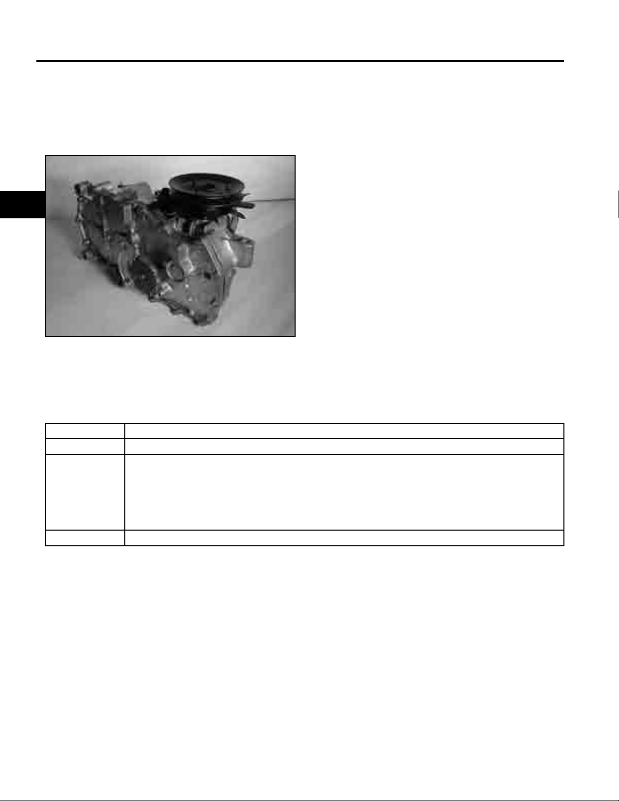
Hydrostatic Transaxles
Identifi cation:
Hydro-Gear EZT Hydrostatic Transaxles
2
MVC-204X
Transaxle Specifi cations
Lubrication SAE 20W-50 API Classifi cation SH/CD
Oil Capacity 1.6 to 1.7 qt. (1.5 to 1.6 liters)
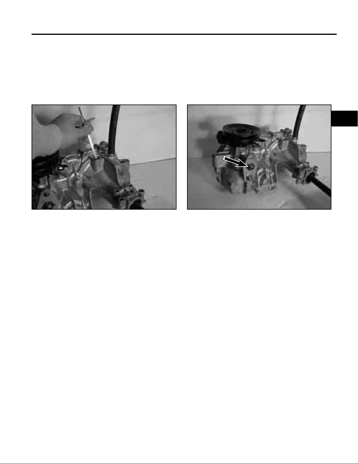
Oil Level The transaxle is a sealed system and does not require periodic checking. Check oil at the oil
fi ll plug location only. Do not check the oil at the vent tube. Checking oil at the vent tube will
only give you a false reading or no reading at all, since this is the oil expansion area. If the oil
needs to be checked, the transaxle must be removed to check oil level and IT CAN BE ONLY
CHECKED COLD. There is a fi ll plug located at the top of the transaxle. To check the level of
the oil, remove the fi ll plug. Oil level should be 3/4” (1.9cm) from the top of the oil fi ll plug.
Fluid Change The transaxle is factory fi lled and does not require regular oil changes.
A2-6 TimeCutter Z / Precision Z Service Manual
Page 15
Hydrostatic Transaxles cont.
Note: If you are replacing the transaxle, after you
have installed the hydro rods, remove the nut
and washer located on the cam plate. Also,
check the oil prior to installation.
SPECIFICATIONS
2
MVC-206X MVC-205X
A2-7TimeCutter Z / Precision Z Service Manual
Page 16
SPECIFICATIONS
Torque Specifications
Recommended fastener torque values are listed in the
following tables. For critical applications, as
determined by Toro, either the recommended torque or
a torque that is unique to the application is clearly
identified and specified in the service manual.
These torque specifications for the installation and
2
tightening of fasteners shall apply to all fasteners which
do not have a specific requirement identified in the
service manual. The following factors shall be
considered when applying torque: cleanliness of the
fastener, use of a thread sealant (Loctite), degree of
lubrication on the fastener, presence of a prevailing
torque feature, hardness of the surface underneath of
the fastener’s head, or similar condition which affects
the installation.
As noted in the following tables, torque values should
be reduced by 25% for lubricated fasteners to
achieve the similar stress as a dry fastener. Torque
values may also have to be reduced when the fastener
is threaded into aluminum or brass. The specific
torque value should be determined based on the
aluminum or brass material strength, fastener size,
length of thread engagement, etc.
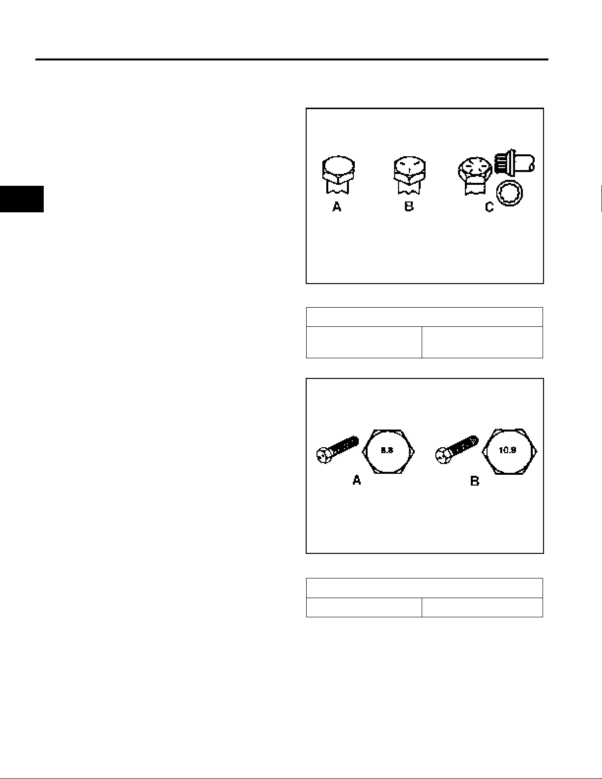
Fastener Identification
Inch Series Bolts and Screws
(A) Grade 1
(B) Grade 5
Figure A
(C) Grade 8
1
The standard method of verifying torque shall be
performed by marking a line on the fastener (head or
nut) and mating part, then back off fastener 1/4 of a
turn. Measure the torque required to tighten the
fastener until the lines match up.
Figure B
Metric Bolts and Screws
(A) Class 8.8 (B) Class 10.9
2
A2-8 TimeCutter Z / Precision Z Service Manual
Page 17

SPECIFICATIONS
2
Standard Torque for Dry, Zinc Plated, and Steel Fasteners (Inch Series)
Grade 1, 5, &
Thread Size
# 6 - 32 UNC
# 6 - 40 UNF 17 ± 2 190 ± 20 25 ± 2 280 ± 20
# 8 - 32 UNC
# 8 - 36 UNF 31 ± 3 350 ± 30 43 ± 4 31 ± 3
# 10 - 24 UNC
#10 - 32 UNF 48 ± 4 540 ± 45 68 ± 6 765 ± 70
1/4 - 20 UNC 48 ± 7 53 ± 7 599 ± 79 100 ± 10 1125 ± 100 140 ± 15 1580 ± 170
1/4 - 28 UNF 53 ± 7 65 ± 10 734 ± 113 115 ± 10 1300 ± 100 160 ± 15 1800 ± 170
5/16 - 18 UNC 115 ± 15 105 ± 17 1186 ± 169 200 ± 25 2250 ± 280 300 ± 30 3390 ± 340
5/16 - 24 UNF 138 ± 17 128 ± 17 1446 ± 192 225 ± 25 2540 ± 280 325 ± 30 3670 ± 340
3/8 - 16 UNC 16 ± 2 16 ± 2 22 ± 3 30 ± 3 41 ± 4 43 ± 4 58 ± 5
3/8 - 24 UNF 17 ± 2 18 ± 2 24 ± 3 35 ± 3 47 ± 4 50 ± 4 68 ± 5
7/16 - 14 UNC 27 ± 3 27 ± 3 37 ± 4 50 ± 5 68 ± 7 70 ± 7 68 ± 9
7/16 - 20 UNF 29 ± 3 29 ± 3 39 ± 4 55 ± 5 75 ± 7 77 ± 7 104 ± 9
1/2 - 13 UNC 30 ± 3 48 ± 7 65 ± 9 75 ± 8 102 ± 11 105 ± 10 142 ± 14
1/2 - 20 UNF 32 ± 3 53 ± 7 72 ± 9 85 ± 8 115 ± 11 120 ± 10 163 ± 14
5/8 - 11 UNC 65 ± 10 88 ± 12 119 ± 16 150 ± 15 203 ± 20 210 ± 20 285 ± 27
5/8 - 18 UNF 75 ± 10 95 ± 15 129 ± 20 170 ± 15 230 ± 20 240 ± 20 325 ± 27
3/4 - 10 UNC 93 ± 12 140 ± 20 190 ± 27 265 ± 25 359 ± 34 374 ± 35 508 ± 47
3/4 - 16 UNF 115 ± 15 165 ± 25 224 ± 34 300 ± 25 407 ± 34 420 ± 35 569 ± 47
7/8 - 9 UNC 140 ± 20 225 ± 25 305 ± 34 430 ± 45 583 ± 61 600 ± 60 813 ± 81
7/8 - 14 UNF 155 ± 25 260 ± 30 353 ± 41 475 ± 45 644 ± 61 660 ± 60 895 ± 81
8 with Thin
Height Nuts
In-lb In-lb N-cm In-lb N-cm In-lb N-cm
10 ± 2 13 ± 2 147 ± 23
13 ± 2 25 ± 5 282 ± 30
18 ± 2 30 ± 5 339 ± 56
ft-lb ft-lb N-m ft-lb N-m ft-lb N-m
SAE Grade 1 Bolts, Screws,
Studs, & Sems with Regular
Height Nuts (SAE J995
Grade 2 or Stronger Nuts)
SAE Grade 5 Bolts, Screws,
Studs, & Sems with Regular
Height Nuts (SAE J995
Grade 2 or Stronger Nuts)
15 ± 2 170 ± 20 23 ± 2 260 ± 20
29 ± 3 330 ± 30 41 ± 4 460 ± 45
42 ± 4 475 ± 45 60 ± 6 674 ± 70
SAE Grade 8 Bolts, Screws,
Studs, & Sems with Regular
Height Nuts (SAE J995
Grade 2 or Stronger Nuts)
2
Note: Reduce torque values listed in the table above
by 25% for lubricated fasteners. Lubricated fasteners
are defined as threads coated with a lubricant such as
oil, graphite, or thread sealant such as Loctite.
Note: Torque values may have to be reduced when
installing fasteners into threaded aluminum or brass.
The specific torque value should be determined based
on the fastener size, the aluminum or base material
strength, length of thread engagement, etc.
Note: The nominal torque values listed above for
Grade 5 and 8 fasteners are based on 75% of the
minimum proof load specified in SAE J429. The
tolerance is approximately
value. Thin height nuts include jam nuts.
± 10% of the nominal torque
A2-9TimeCutter Z / Precision Z Service Manual
Page 18

SPECIFICATIONS
Standard Torque for Dry, Zinc, and Steel Fasteners (Metric Fasteners)
Class 8.8 Bolts, Screws, and Studs with
Thread Size
M5 X 0.8 57 ± 5 in-lb 640 ± 60 N-cm 78 ± 7 in-lb 885 ± 80 N-cm
M6 X 1.0 96 ± 9 in-lb 1018 ± 100 N-cm 133 ± 13 in-lb 1500 ± 150 N-cm
M8 X 1.25 19 ± 2 ft-lb 26 ± 3 N-m 27 ± 2 ft-lb 36 ± 3 N-m
M10 X 1.5 38 ± 4 ft-lb 52 ± 5 N-m 53 ± 5 ft-lb 72 ± 7 N-m
2
M12 X 1.75 66 ± 7 ft-lb 90 ± 10 N-m 92 ± 9 ft-lb 125 ± 12 N-m
M16 X 2.0 166 ± 15 ft-lb 225 ± 20 N-m 229 ± 22 ft-lb 310 ± 30 N-m
M20 X 2.5 325 ± 33 ft-lb 440 ± 45 N-m 450 ± 37 ft-lb 610 ± 50 N-m
Note: Reduce torque values listed in the table above
by 25% for lubricated fasteners. Lubricated fasteners
are defined as threads coated with a lubricant such as
oil, graphite, or thread sealant such as Loctite.
Note: Torque values may have to be reduced when
installing fasteners into threaded aluminum or brass.
The specific torque value should be determined based
on the fastener size, the aluminum or base material
strength, length of thread engagement, etc.
Regular Height Nuts
(Class 8 or Strong Nuts)
Class 10.9 Bolts, Screws, and Studs with
Regular Height Nuts (
Class 10 or Strong Nuts)
Note: The nominal torque values listed above are
based on 75% of the minimum proof load specified in
SAE J1199. The tolerance is approximately
the nominal torque value. Thin height nuts include jam nuts.
± 10% of
A2-10 TimeCutter Z / Precision Z Service Manual
Page 19

TIMECUTTER Z SERVICE MANUAL
CHASSIS
Safety Information . . . . . . . . . . . . . . . . . . . . . . . . . . . . . . . . . .
Specifications . . . . . . . . . . . . . . . . . . . . . . . . . . . . . . . . . . . . .
Chassis. . . . . . . . . . . . . . . . . . . . . . . . . . . . . . . . . . . . . . . . . .
Hydro-Gear Transaxle. . . . . . . . . . . . . . . . . . . . . . . . . . . . . . .
Electrical Systems. . . . . . . . . . . . . . . . . . . . . . . . . . . . . . . . . .
1
2
3
4
5
Mower Decks. . . . . . . . . . . . . . . . . . . . . . . . . . . . . . . . . . . . . .
TimeCutter Z Service Manual 3 - 1
6
Page 20
CHASSIS
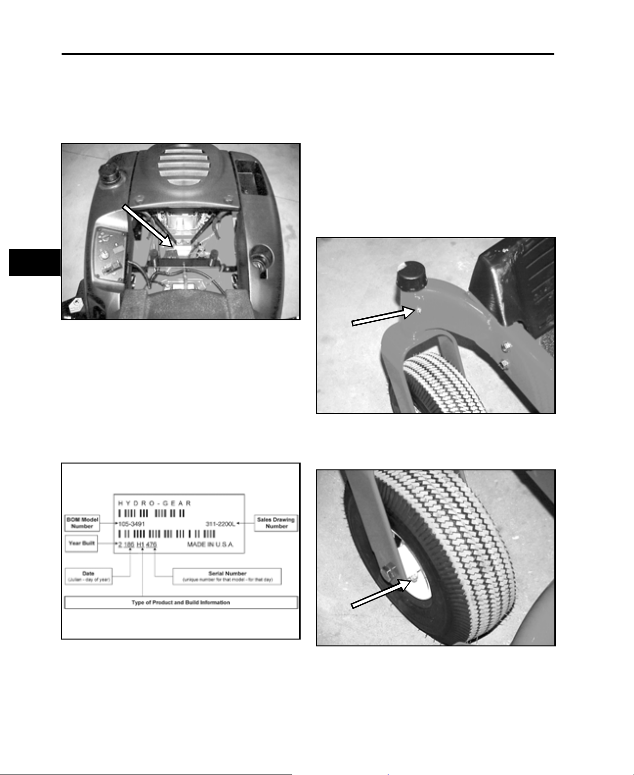
Model and Serial Number Location
The unit model and serial number plate is located on
the frame under the seat as shown in the illustration
(Figure 3).
3
Figure 3
Engine Model and Serial Number
Identification
Greasing and Lubrication
The unit should be greased every 25 hours or more
often when operated in dusty , dirty or sandy conditions.
Grease Type: No. 2 general purpose lithium base
grease.
There are four grease fittings located in the front wheel
area:
1. One grease fitting is located in each of the cast
iron pivot castor supports (Figure 5).
mvc-049
Consult the appropriate engine manufacturer’s service
literature for the location and translation of the engine
model and serial number information (Figure 4).
Transaxle Model and Serial Number
Figure 4
Figure 5
2. One grease fitting is located on each front wheel
hub on the front tire (Figure 6).
Figure 6
mvc-050
mvc-051
3 - 2 TimeCutter Z Service Manual
Page 21
CHASSIS
Front Castor Fork Removal and
Installation
Removal
1. Park the machine on a level surface, disengage
the blade control (PTO), and turn the ignition key
to OFF to stop the engine. Remove the ignition
key.
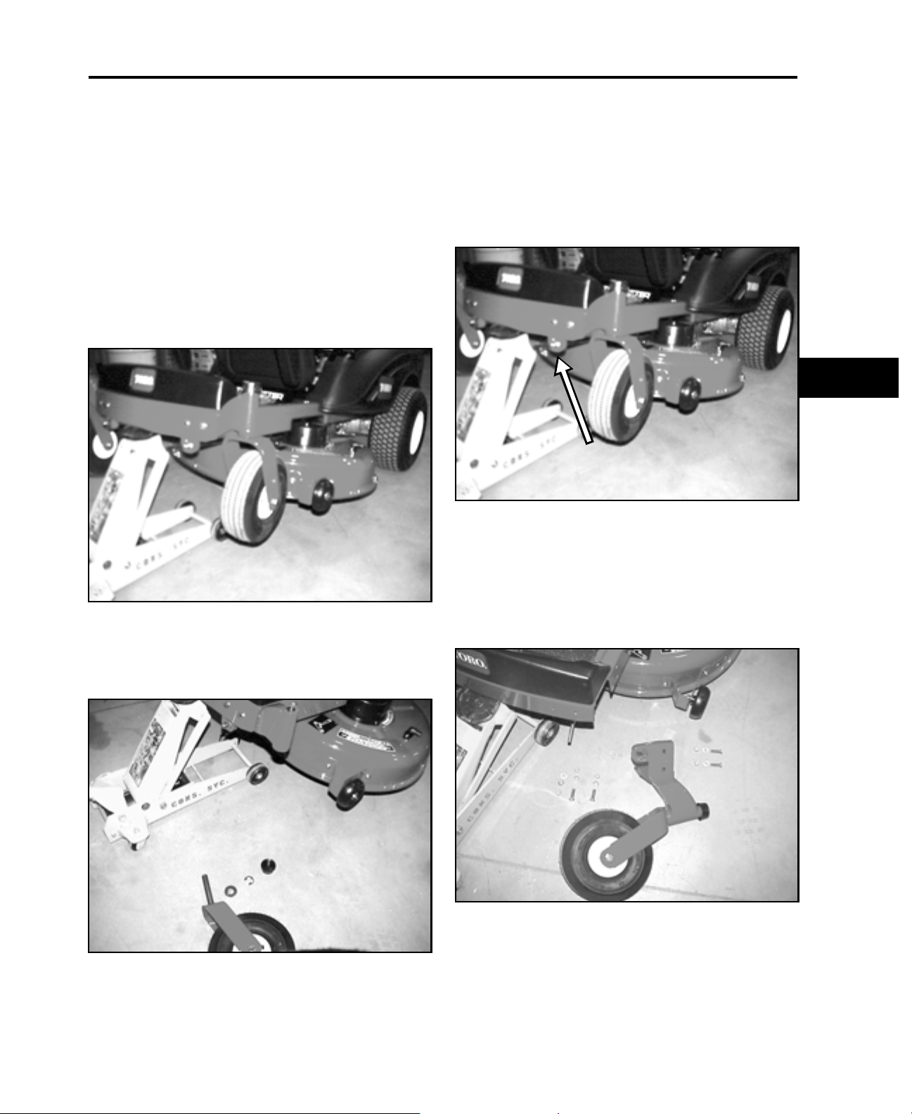
2. Raise the front of the unit high enough so you
have enough room to lower the castor forks from
the pivot castor supports (Figure 7).
Installation
Follow the removal procedure in reverse.
Castor Support Removal
1. Raise the front end of the unit (Figure 9).
Figure 9
3
mvc-053
Figure 7
3. Remove the plastic dust cover, e-ring, and
washer. Slide the ca stor fork down out of the pivot
castor support (Figure 8).
mvc-053
2. Remove the locknut, nut, and washer from the
mower deck hanger rod (Figure 9).
3. Remove the (4) nuts, bolts, and washers holding
the castor support to the frame and remove the
castor support (Figure 10).
Figure 10
mvc-070
Figure 8
TimeCutter Z Service Manual 3 - 3
mvc-070
Page 22
CHASSIS
Installation
Reverse the order of removal. The mower deck, frontto-rear blade scope, needs to be adjusted, Refer to
“Adjusting the Front-to-Rear Blade Slope” on page 6 -
3.
Side Panel Removal
Left Side Panel Removal
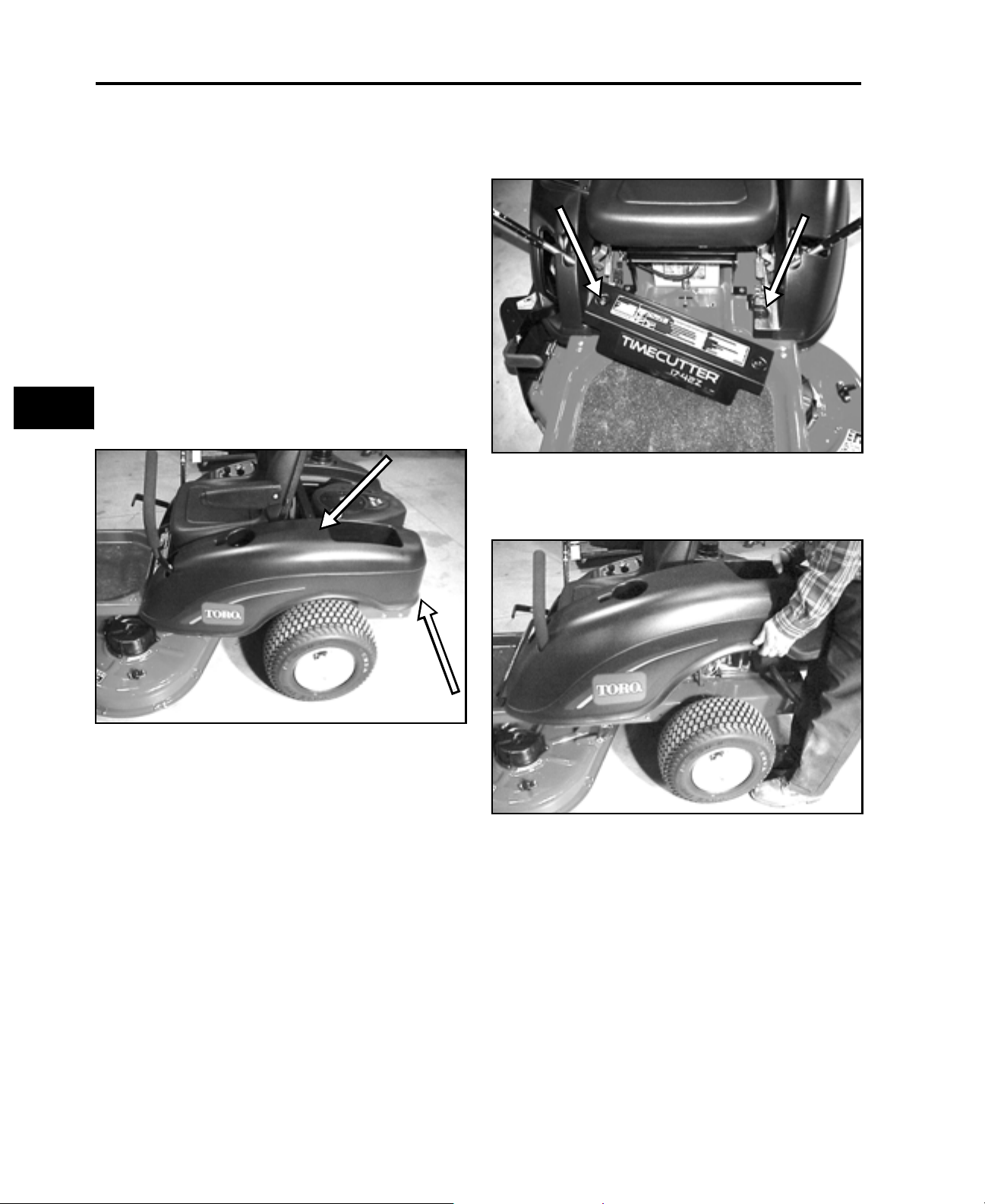
1. Remove the three fasteners holding the rear
portion of the left side panel. Two fasteners are
located in the middle, under the side panel
connecting the panel to the rear support bracket.
3
The third fastener is located at the rear of the
panel (Figure 11).
2. Remove the two carriage bolts and nuts fastening
the front bracket support to the frame and remove
the bracket (Figure 12).
Figure 12
3. Remove the left side panel off of the frame (Figure
13).
mvc-060
Figure 11
3 - 4 TimeCutter Z Service Manual
mvc-059
Figure 13
Installation
Follow the removal procedure in reverse.
mvc-062
Page 23

CHASSIS
Right Side Panel and Gas Tank
Removal
1. Before removing the right side panel, disconnect
the negative battery cable and shut the fuel off at
the fuel valve, located under the fuel tank.
2. The left side panel must be removed first before
the right side panel can be removed. Follow
procedures for removing the left side panel.
3. Remove the 4 screws on the control panel and
move the control panel away from the side panel
(Figure 14).
5. Remove the two bolts holding rear bracket support
to the brace assembly (Figure 16).
Figure 16
6. To ease removal of the side panel, remove the two
bolts holding the right side motion control lever
and remove the lever. Remove the right side panel
cover, leaving the fuel tank in place (Figure 17).
mvc-066
3
Figure 14
4. Remove the bolt and nut securing the rear of the
side panel to the frame (Figure 15).
Figure 15
mvc-065
mvc-146
Figure 17
mvc-067
TimeCutter Z Service Manual 3 - 5
Page 24

CHASSIS
7. Disconnect the gas line at the carburetor.
Remove the two spring clips located at the bottom
of the gas tank, disconnect the gas line and
remove the tank (Figure 18).
3
Figure 18
Installation
Reinstall the gas tank and right side panel in reverse
order.
mvc-068
2. Unbolt the flange bearing from the left side of the
unit and remove from the end of the lift arm shaft
(Figure 20).
Figure 20
3. Remove the lift arm assembly (Figure 21).
mvc-073
Lift Arm Assembly
Removal
1. Remove the two bolts and washers retaining the
lift lever to the lift block and remove them from the
lift arm assembly (Figure 19).
Figure 19
mvc-072
Figure 21
Installation
Reverse the order of removal.
mvc-074
3 - 6 TimeCutter Z Service Manual
Page 25

CHASSIS
Belt Replacement
Removal
1. Before removing or replacing the belt, disconnect
the negative battery cable and shut the fuel off at
the fuel valve, located under the fuel tank.
2. Remove the mower drive belt from the electric
PTO clutch.
3. Disconnect the plug connection to the electric
clutch (Figure 22).
5. Disconnect the spring connected to the rear idler
arm and remove the lower drive belt off the engine
pulley and around the left transaxle pulley (Figure
24).
Figure 24
6. Disconnect the front idler spring from the front
spring bracket and work the belt off the right
transaxle pulley , then of f the engine pulley (Figure
25).
mvc-083
3
Figure 22
4. Remove the PTO clutch bolt and remove the
electric clutch (Figure 23).
Figure 23
mvc-079
mvc-081
Figure 25
mvc-084
TimeCutter Z Service Manual 3 - 7
Page 26

CHASSIS
Belt Installation
1. Install belt around the upper groove of the engine
drive pulley and then around the right side
transaxle pulley. Install idler spring to the front
spring bracket (Figure 26).
3
Figure 26
3. Apply anti-seize lubricant on the crankshaft and
install the electric PTO clutch on the engine
crankshaft; make sure the slot on the clutch goes
into the clutch stop bracket.
NOTE: Loctite 242 should be applied to the threads of
the clutch bolt before installing. Torque the clutch bolt
to 50 - 60 ft. lbs. Reinstall the electrical plug
connection into the clutch.
mvc-091
2. Install the second drive belt around the left side
transaxle pulley and then work it around the
engine drive pulley. Install idler spring to the rear
spring bracket (Figure 27).
Figure 27
mvc-093
Figure 28
4. Install the mower drive belt around the electric
PTO clutch.
5. Reconnect the negative battery cable and turn the
fuel ON at the fuel valve, located under the fuel
tank.
mvc-094
3 - 8 TimeCutter Z Service Manual
Page 27

HYDRO-GEAR TRANSAXLE
TIMECUTTER Z SERVICE MANUAL
Safety Information . . . . . . . . . . . . . . . . . . . . . . . . . . . . . . . . . .
Specifications . . . . . . . . . . . . . . . . . . . . . . . . . . . . . . . . . . . . .
Chassis . . . . . . . . . . . . . . . . . . . . . . . . . . . . . . . . . . . . . . . . . .
Hydro-Gear Transaxle. . . . . . . . . . . . . . . . . . . . . . . . . . . . . .
Electrical Systems. . . . . . . . . . . . . . . . . . . . . . . . . . . . . . . . . .
1
2
3
4
5
Mower Decks. . . . . . . . . . . . . . . . . . . . . . . . . . . . . . . . . . . . . .
TimeCutter Z Service Manual 4 - 1
6
Page 28

HYDRO-GEAR TRANSAXLE
Hydro-Gear (310-2200) EZT™
Transaxles
Internal Service
Internal service information is contained in the HydroGear Transaxle Service Manual, Form # 492-4778.
Note: Under warranty, the transaxles should NOT
disassembled or internally repaired, unless authorized
by either your Distributor Service Manager or The Toro
Company.
Fluid Change
The Hydro-Gear transaxles do not require periodic oil
changes under normal conditions. In the event of oil
contamination or degradation, oil replacement may
correct certain performance problems.
Using the “Transaxle Removal” procedure”, remove the
transaxle, and drain the oil through the fluid fill port. Fill
4
unit to the proper level; refer to “General
Specifications” on page 2 - 2. Reinstall transaxles and
perform “Purging Procedures – Hydro-Gear
Transaxles” on page 4 - 8.
.
be
2. Raise the rear end of the unit and remove the right
and left rear tires (Figure 29).
Figure 29
3. Install jack stands in front of the transaxles (Figure
30).
mvc-134
Transaxle Removal
The right and left transaxles are secured to a hydro
mount frame. The hydro mount frame is fastened to the
main frame. If either one of the transaxles need to be
removed from the unit, the whole hydro mount frame
must be removed with both transaxles on it.
1. Disconnect the negative battery cable from the
battery.
Figure 30
4. Remove the hydrostatic transaxle drive belts, refer
to “Belt Replacement” on page 3 - 7.
mvc-117
4 - 2 TimeCutter Z Service Manual
Page 29

HYDRO-GEAR TRANSAXLE
5. Remove the bolt, washer, and spacer ret aining the
brake arm on both the right and left transaxles.
Make sure dirt and debris is cleaned off around
the vent hose connected to each transaxle, then
remove the vent hoses. Cover the open hole in
each transaxle with tape to prevent dirt entry
(Figure 31).
Figure 31
mvc-096
7. Remove the 4 bolts and washers on the left side
of the frame (Figure 33).
Figure 33
8. Remove the 4 bolts located on th e right side of the
frame (Figure 34).
mvc-739
4
6. Loosen the four bolts and nuts holding the
transaxles to the hydro support brackets (Figure
32).
Figure 32
mvc-099
Figure 34
mvc-736
TimeCutter Z Service Manual 4 - 3
Page 30

HYDRO-GEAR TRANSAXLE
9. Slowly lower the hydro frame and the transaxles
down about half way out of the frame of the unit
and stop.
Figure 35
10. Disconnect both the right and left hydro rods by
4
removing the bolt and nut through the frame of the
unit (Figure 36).
mvc-114
12. Hydro mount frame and the two transaxles
removed from the frame of the unit (Figure 37).
Figure 37
mvc-105
Removing Transaxles from the
Hydro Mount Frame
1. Remove the bolt and nut retaining bypass arm to
the bypass lever and remove the arm off the hydro
frame (Figure 38).
Figure 36
11. Lift up on the front of the hydro frame and move
the hydro mount frame toward the rear end of the
unit. Use caution not to bend the right and left
brake rods and the hydro rods (Figure 36).
4 - 4 TimeCutter Z Service Manual
mvc-115
Figure 38
mvc-106
Page 31

HYDRO-GEAR TRANSAXLE
2. Remove the two bolts, washers, and nuts
securing the transaxle to the hydro frame and
remove the transaxle from the hydro frame (Figure
39).
Figure 39
3. NOTE: If you are replacing the transaxle, after
installing the hydro rods, remove the nut and
washer on the cam plate (Figure 40).
mvc-110
Wheel Hub Removal
1. Remove the bolt holding the locking tab to the hub
(Figure 41).
Figure 41
2. Remove the center hub bolt and washer. Slide
the hub off the axle shaft (Figure 42).
mvc-111
4
Figure 40
Assembly
Reverse the order of removal.
TimeCutter Z Service Manual 4 - 5
mvc-206
Installation Wheel Hub
Reverse the order of removal. Apply anti-seize
lubricant on the axle and apply Loctite 242 to the
threads of the bolt holding the locking tab and tighten.
Figure 42
mvc-113
Page 32

HYDRO-GEAR TRANSAXLE
Transaxle Installation
1. Slide the hydro frame/transaxles under the frame
(Figure 43).
Figure 43
4
2. Lift the front of the hydro frame up into the frame,
making sure both the hydro rods and the brake
rods are in the right positions. Drop it down so the
notches in the hydro frame engage with the two
bolts and tubes located on the frame of the unit.
mvc-114
4. Install the 4 bolts on both the right and left sides of
the frame and tighten (Figure 45).
Figure 45
5. Install and tighten the four bolts on the right and
left support brackets (Figure 46).
mvc-739
3. Before raising the rear portion of the transaxle,
connect the two hydro rods to the hydro control
arm (Figure 44).
Figure 44
mvc-115
Figure 46
mvc-099
4 - 6 TimeCutter Z Service Manual
Page 33

HYDRO-GEAR TRANSAXLE
6. Install the transaxle vent tubes to the transaxles.
Make sure the protective caps fit under the rear
bracket support (Figure 47).
Figure 47
7. Install transaxle drive belts. Refer to “Belt
Installation” on page 3 - 8.
8. Leave the two brake arms disconnected from the
transaxles. Make sure the brake arms are clear of
the cog brake discs (Figure 48).
mvc-116
9. Put a floor jack under the frame and raise the unit.
Remove the floor jack stands and install the right
and left rear tires. For stability, position the floor
jack stands at the rear of the unit (Figure 49).
Figure 49
10. Connect the negative battery cable.
11. Unplug the seat switch and temporarily connect a
jumper wire across the plug connector on the
harness (Figure 50).
mvc-128
4
Figure 48
TimeCutter Z Service Manual 4 - 7
mvc-735
12. NOTE: When installing a new transaxle in the
machine or if any work was performed internally
on the transaxle or if the oil was changed, make
sure the system is purged prior to doing any
neutral adjustment. Refer to “Purging Procedures
– Hydro-Gear Transaxles” on page 4 - 8.
Figure 50
mvc-130
Page 34

HYDRO-GEAR TRANSAXLE
13. After any service where control linkage was
disturbed or after purging procedures have been
performed, check the neutral adjustment. If the
neutral adjustment needs to be performed, refer to
“Neutral Adjustment” on page 4 - 9.
14. Reconnect the brake levers and check the brakes,
refer to “Brake Adjustment” on page 4 - 11.
15. Remove the jumper wire to the seat and
reconnect the seat switch (Figure 51).
4
Figure 51
16. Remove the jack stands. Operate the unit making
sure the unit and all the safety devices are
working properly.
Purging Procedures – Hydro-Gear
Transaxles
Due to the effects air has on efficiency in hydrostatic
drive applications, it is critical that it be purged from the
system.
These purge procedures should be implemented any
time a hydrostatic system has been opened to facilitate
maintenance, any additional oil has been added to the
system, or a replacement transaxle has been installed.
Air creates inefficiency because its compression and
expansion rate is higher than that of the oil normally
approved for use in hydrostatic drive systems.
The resulting symptoms in hydrostatic systems may
be:
1. Noisy operation.
2. Lack of power or drive after short term operation.
3. High operation temperature and excessive
expansion of “oil”, in the latter case, oil may
overflow.
mvc-133
The following procedures should be performed with the
vehicle wheels off the ground, then repeated under
operating conditions.
1. With the bypass valve open (push position) and
the engine running, slowly move the directional
controls (forward/reverse levers) in both forward
and reverse directions 5 to 6 times; as air is
purged from the transaxles, the oil level will drop.
2. With the bypass valves in the closed position (run
position) and the engine running, slowly move the
directional control levers in both forward and
reverse directions 5 to 6 times.
3. It may be necessary to repeat steps 1 and 2 until
all the air is completely purged from the
transaxles. When the transaxles move forward at
normal speed, purging is complete.
4 - 8 TimeCutter Z Service Manual
Page 35

HYDRO-GEAR TRANSAXLE
Neutral Adjustment
Before making a neutral adjustment, the transaxles
must be warmed up, usually 5 to 10 minutes. Steps to
perform neutral adjustment:
1. Jack-up and support the rear end of the unit.
Place jack stands at the rear to stabilize the unit
(Figure 52).
3. Unplug the seat switch and temporarily connect a
jumper wire across the plug connector on the
harness (Figure 54).
Figure 54
4. Put the forward/reverse levers in the park position
and start the engine. Operate the lever of the
transaxle needing adjustment in forward and
reverse (Figure 55).
mvc-130
4
Figure 52
2. Remove the brake arm on the transaxle, you are
performing the neutral adjustment on. In this case,
we are performing a neutral adjustment on both
transaxles. Make sure the brake arms are clear of
the cog brake system disc (Figure 53).
Figure 53
mvc-128
mvc-735
Figure 55
mvc-136
TimeCutter Z Service Manual 4 - 9
Page 36

HYDRO-GEAR TRANSAXLE
5. Observe the rear tire to see if the wheel is
creeping in forward or reverse, in the neutral
position (Figure 56).
Figure 56
6. If the rear wheel is creeping in forward or reverse,
4
remove the bolt and nut on the end of the control
rod (Figure 57).
mvc-137
7. Move the control rod back and forth and watch the
tire direction. Adjust the rod so that it is mid-point
between forward and reverse wheel rotation.
Now, check the alignment of the bolt on the end of
the control rod. The bolt should enter at a right
angle to the actuator arm assembly (Figure 58).
Figure 58
8. If the bolt is not aligned properly, loosen the jam
nut and turn the ball joint until the holes align so
the bolt on the end of the control rod enters at a
right angle to the actuator arm and then tighten
the jam nut (Figure 59).
mvc-140
Figure 57
4 - 10 TimeCutter Z Service Manual
mvc-138
Figure 59
9. Start the unit up and operate the forward and
reverse levers to make sure it is now neutralized.
Reconnect the brake arms. Refer to “Brake
Adjustment” on page 4 - 11.
mvc-145
Page 37

HYDRO-GEAR TRANSAXLE
10. Reconnect the seat switch and lower the unit to
the ground. Operate the equipment to make sure
the adjustments and the safety devices are
operating properly.
Tracking Adjustments
Tracking adjustment is necessary when the speed of
one transaxle is faster then the other; so that the unit
will not travel in a reasonable straight line. The faster
transaxle must be slowed down to correct this. Before
making this adjustment, ensue there is no other reason
for poor tracking – tire pressure, bent or dragging
wheel, loose linkage, etc. (Figure 60).
Behind the right and left actuator arm is an eccentric
bushing. There is a bolt and nut through the center of
the eccentric bushing. Loosen the bolt and nut and turn
the eccentric bushing to decrease the actuator arm
movement forward. NOTE: The tracking adjustment is
for forward motion only. In reverse, you may have a
slight speed difference; this is normal. Tighten the bolt
and nut on the eccentric bushing when you obtain
equal tracking in the forward position (Figure 61).
4
Figure 60
mvc-183
Figure 61
mvc-184
Brake Adjustment
1. Move the forward/reverse control handles to the
run position (handles inward) (Figure 62).
Figure 62
mvc-176
TimeCutter Z Service Manual 4 - 11
Page 38

HYDRO-GEAR TRANSAXLE
2. Pull back on the brake rod and adjust the nut on
the end of the rod (Figure 63) until the tab at the
bottom of the brake lever and the tab located on
the transaxle housing meet (Figure 64).
Figure 63
4
mvc-177
3. Move the forward/reverse handle to the p ark
position (handles out) and then back to the run
position (handles in). Make sure the brake arms
are clear from the disc brake cogs in the run
position (Figure 65).
Figure 65
Actuator Arm Removal
mvc-182
Figure 64 mvc-179
1. Remove side panel, see “Side Panel Removal” on
page 3 - 4.
2. Unbolt and remove the damper control strut
(Figure 66).
Figure 66
mvc-147
4 - 12 TimeCutter Z Service Manual
Page 39

HYDRO-GEAR TRANSAXLE
3. Remove the bolt and nut retaining the hydro rod to
the actuator arm (Figure 67).
Figure 67
4. Remove the nut on the brake link (Figure 68).
mvc-150
5. Remove the bolt and nut retaining the rear of the
hydro rod to the control arm and slide the hydro
rod towards the rear (Figure 69).
Figure 69
6. Unplug and remove the park brake switch from
the lower bellcrank bracket (Figure 70).
mvc-103
4
Figure 68
TimeCutter Z Service Manual 4 - 13
mvc-152
Figure 70
mvc-157
Page 40

HYDRO-GEAR TRANSAXLE
7. Remove the bolt and nut holding the bellcrank and
remove (Figure 71).
Figure 71
8. Slide the actuator off the welded stud (Figure 72).
4
mvc-158
Actuator Arm Installation
1. Slide the actuator on the welded stud and install a
washer and nut and tighten (Figure 73).
Figure 73
2. Install the park brake switch in the lower bellcrank
bracket and plug in the wire connector.
mvc-155
Figure 72
mvc-159
3. Install the bellcrank with bolt and nut. The washer
gets installed between the brackets (Figure 74).
Figure 74
mvc-161
4 - 14 TimeCutter Z Service Manual
Page 41

HYDRO-GEAR TRANSAXLE
4. Install the brake link to the bellcrank with a nut and
tighten (Figure 75).
Figure 75
mvc-162
5. Connect the rear of the hydro rod to the transaxle
control arm and tighten (Figure 76).
Figure 76
6. Install the hydro rod to the actuator.
mvc-103
4
TimeCutter Z Service Manual 4 - 15
Page 42

HYDRO-GEAR TRANSAXLE
WARNING
Do not attempt any servicing or adjustments
with the engine running.
Use extreme caution while inspecting the
drive belt assembly and all vehicle linkage!
Follow all safety procedures outlined in
the vehicle owner’s manual.
310-220 EZT™ Troubleshooting Checklist
Possible Cause Corrective Action
UNIT OPERATES IN ONE DIRECTION ONLY
• Control linkage bent or out of adjustment.
• Drive belt slipping or pulley damaged.
4
• Vehicle tires improperly inflated
• Control linkage bent or out of adjustment
• Bypass assembly sticking
• Oil level low or contaminated oil
• Excessive loading
• Loose parts
• Bypass assembly sticking
• Air trapped in hydraulic system
• Engine speed low
• Control linkage bent or out of adjustment
• Drive belt slipping or pulley damaged
• Oil level low or contaminated oil
• Excessive loading
• Bypass assembly sticking
• Air trapped in hydraulic system
• Debris buildup around transaxle
• Cooling fan damaged
• Oil level low or contaminated oil
• Excessive loading
• Air trapped in hydraulic system
• Damaged seals, housing, or gaskets
• Air trapped in hydraulic system
VEHICLE DOES NOT DRIVE/TRACK STRAIGHT
UNIT HAS NO/LOW POWER
UNIT IS OPERATING HOT
TRANSAXLE LEAKS OIL
In many cases, problems with the 310-2200 are not
related to a defective transaxle, but are caused by
slipping drive belts, partially engaged bypass valves,
and loose or damaged control linkages. The table
below provides a troubleshooting checklist to help
determine the cause of operational problems.
• Repair or replace linkage.
• Repair or replace drive belt or pulley.
• Refer to vehicle manufacturer suggested pressure
• Repair or replace linkage
• Repair or replace bypass
UNIT IS NOISY
• Fill to proper level or change oil
• Reduce vehicle loading
• Repair or replace loose parts
• Repair or replace linkage
• Purge hydraulic system
• Adjust to correct setting
• Repair or replace linkage
• Repair or replace drive belt or pulley
• Fill to proper level or change oil
• Reduce vehicle loading
• Repair or replace linkage
• Purge hydraulic system
• Clean off debris
• Repair or replace cooling fan
• Fill to proper level or change oil
• Reduce vehicle loading
• Purge hydraulic system
• Replace damaged component
• Purge hydraulic system
4 - 16 TimeCutter Z Service Manual
Page 43

TIMECUTTER Z SERVICE MANUAL
ELECTRICAL SYSTEM
Safety Information . . . . . . . . . . . . . . . . . . . . . . . . . . . . . . . . . .
Specifications . . . . . . . . . . . . . . . . . . . . . . . . . . . . . . . . . . . . .
Chassis . . . . . . . . . . . . . . . . . . . . . . . . . . . . . . . . . . . . . . . . . .
Hydro-Gear Transaxle. . . . . . . . . . . . . . . . . . . . . . . . . . . . . . .
Electrical Systems. . . . . . . . . . . . . . . . . . . . . . . . . . . . . . . . .
1
2
3
4
5
Mower Decks. . . . . . . . . . . . . . . . . . . . . . . . . . . . . . . . . . . . . .
TimeCutter Z Service Manual 5 - 1
6
Page 44

ELECTRICAL SYSTEM
Electrical System
Two things happen when turning the ignition switch to
the “START” position: (1) Current flows from the
ignition switch to the starter solenoid coil terminal. (2)
At the same time, current will flow through the PTO
(Power Take Off) switch in the OFF position, through
both the brake switches, in the OFF or P ARK position,
to the coil terminal of the interlock relay (kill relay). The
interlock relay (kill relay) activates and takes the engine
electronic ignition ground wire off ground to allow the
engine to spark and grounds the starter solenoid to
engage the starter motor of the engine.
Relay (Kill Relay)
Purpose
The relay used in the TimeCutter
or disconnect the engine electronic ignition and starter
solenoid from chassis ground.
Location
Z is used to connect
2. Switch: Terminals 30, 87, and 87a are actually
part of a single pole, double throw (SPDT) switch.
Terminal 30 is the common lead. The switch is
spring loaded so that 30 and 87a are connected
when the coil is not energized. When the coil is
energized, the switch is “thrown” and 30 and 87
are connected (Figure 78).
Figure 78
mvc-671
The relay is located in front of the engine (Figure 77).
How it Works
5
Figure 77
A relay is an electrically actuated switch.
1. Coil: T erminals 85 and 86 are connected to a coil.
Applying 12 volts to these terminals energizes the
coil turning it into an electromagnet.
mvc-190
Testing
1. Disconnect the relay from the harness.
2. Verify the coil resistance between terminals 85
and 86 with a multimeter (ohms setting).
Resistance should be from 70 to 90 ohms. There
should be continuity between terminals 87a and
30.
3. Connect multimeter (ohms setting) leads to relay
terminals 30 and 87. Ground terminal 86 and
apply +12 VDC to 85. The relay should make and
break continuity between terminals 30 and 87 as
12 VDC is applied and removed from terminal 85.
4. Connect multimeter (ohms setting) leads to relay
terminals 30 and 87a. Apply +12 VDC to terminal
85. With terminal 86 still grounded, the relay
should break and make continuity between
terminals 30 and 87a as 12 VDC is applied and
removed from terminal.
5 - 2 TimeCutter Z Service Manual
Page 45

ELECTRICAL SYSTEM
5. Disconnect voltage and multimeter leads from
relay terminals (Figure 79).
Figure 79
Solenoid
Purpose
xlrelay
How it Works
The solenoid has two primary parts. One, a coil of wire
wrapped around an iron core. Whenever 12 volts is
applied to the coil, it becomes a magnet. The other
part is a bar type switch. Because it has a large
contact area with the contact terminals, it can easily
handle the high current loads required by the starter
motor of the engine.
When 12 volts is applied to the coil, it becomes an
electromagnet. This quickly pulls the cbar toward the
contacts and closes the switch. When power is
removed from the coil, the spring loaded bar returns to
its “normally open” position. The solenoid closes and
opens the switch very quickly. This minimizes the
“arcing” that can damage other type of switches.
The ignition switch is protected because only a small
amount of current is needed to activate the coil.
The solenoid’s purpose is simply to connect the battery
to the starter motor on the engine when the ignition
switch is turned to “START”. The solenoid is used to
protect the ignition switch from the high current drawn
by the starter motor.
Location
The solenoid is located on the frame in front of the
engine (Figure 80).
Figure 81
Testing
1. Disconnect the solenoid from the wiring harness.
2. With a multimeter (ohms setting), check to ensure
that terminals “c” and “d” are open (no continuity).
3. Apply +12 VDC to terminal “a” and ground
terminal “b”. Terminals “c” and “d” should now be
closed (continuity) (Figure 81).
xl solenoid
5
Figure 80
TimeCutter Z Service Manual 5 - 3
mvc-191
Page 46

ELECTRICAL SYSTEM
4. You should be able to hear the solenoid switch
“click” when you make the connection (Figure 82).
B
C
A
Figure 82
(A) & (B) Coil Terminals (C) & (D) Contact Terminals
Ignition Switch
Purpose
5
The ignition switch provides the proper switching for
the starter, ignition, accessories, and safety circuits.
Location
D
mvc-675
How it Works
Detents inside the switch give it 3 positions: OFF , RUN,
and START. The START position is spring loaded so
the cylinder automatically returns to RUN once the key
is released (Figure 84).
B
S
I
Figure 84
Ignition Switch
B = Battery voltage “in”
S = Starting Circuit
I = Safety & Starting Circuit
A = Alternator/Regulator Circuit
Y = Safety & Starting Circuit
X = Safety/Start/Light Circuit
A
Y
X
mvc-166
The ignition switch is located on the control panel, to
the right side of the operator (Figure 83).
Figure 83
5 - 4 TimeCutter Z Service Manual
mvc-196
Testing
1. Disconnect the switch from the wiring harness.
2. Verify that continuity exists between the terminals
listed for the switch position. Verify that there is
NO continuity between terminals not listed for the
switch position.
OFF No continuity between terminals
RUN Continuity - B I A and X Y
START Continuity - B I S
Page 47

ELECTRICAL SYSTEM
PTO Switch
Purpose
The PTO (Power Take Off) switch is typically used to
turn on the Electric PTO Clutch and to function as part
of the safety interlock system.
Location
The PTO switch is located on the control panel, to the
right side of the operator (Figure 85).
How it Works
When the PTO switch is pulled out to the ON position,
contacts inside the switch electrically connect various
terminals. One terminal is connected to the wire that
goes directly to the electric clutch. When the PTO is
pulled out to the ON position, voltage flows to the
electric clutch and engages.
Testing
1. Disengage the PTO, set the parking brake, and
turn the ignition to OFF and remove the key.
2. Disconnect the wiring harness from the PTO
switch.
3. Press in on the locking tabs, on each side of the
switch, and pull the switch out of the control panel.
4. Verify that there is continuity between the
appropriate terminals in the ON and OFF positions
(Figure 86).
5. Replace the switch if your test results do not
correspond with those given in Figure 86.
Figure 85
mvc-196
6. Mount the PTO switch back into the control panel
and reinstall the wiring harness.
5
TimeCutter Z Service Manual 5 - 5
Page 48

ELECTRICAL SYSTEM
5
Figure 86
2-24
5 - 6 TimeCutter Z Service Manual
Page 49

ELECTRICAL SYSTEM
Electric (PTO) Clutch
Purpose
This clutch electrically controls the engagement and
disengagement of the Power Take Off (PTO) pulley.
Location
The electric clutch is located on the PTO end of the
engine crankshaft (Figure 87).
Coil Resistance Measurement
1. Disengage the PTO, set the parking brake, turn
the ignition to OFF, and remove the key.
2. Disconnect clutch wire connector.
3. Set the multimeter or volt/ohm meter to check
resistance (ohms).
4. Connect the meter lead wires to the wires in the
clutch connector (Figure 88).
Figure 87
How it Works
The PTO clutch is composed of three major
components; the field, the clutch plate, and the friction
plate. The clutch plate always turns with the engine.
The field is a coil of wire on an iron core, which
becomes an electromagnet when power is applied.
The friction plate is the only piece that can slide up and
down on the crankshaft axis. It is normally spring
loaded so that it is not in contact with the clutch plate
and is pressed against the brake material opposite the
clutch. When power is applied, the friction plate is
drawn toward the clutch plate and the two rotate as
one.
Testing
If the electric PTO clutch is not engaging or is
suspected as a cause of electrical problems, use the
troubleshooting steps. These procedures will help you
determine if the clutch has failed or is the cause of the
electrical problem.
mvc-195
Figure 88
5. The meter should read between 2.40 ohms and
3.40 ohms. If the reading is above or below these
readings, the field has failed and needs to be
replaced. If the reading is between these two
limits, measure the clutch current draw.
Measuring Clutch Current Draw
1. Disengage the PTO, set the parking brake, turn
the ignition key to OFF, and remove the key.
2. Disconnect the clutch wire connector.
3. Set the multimeter to check amps (10 amp scale).
4. Connect the positive meter lead to the tractor
terminal (1) of the clutch wire, Figure 89.
5. Connect the negative meter lead to the
corresponding wire terminal (3), Figure 89.
6. Connect a short jumper lead from terminal (2) to
terminal (4), Figure 89.
3-6
5
TimeCutter Z Service Manual 5 - 7
Page 50

ELECTRICAL SYSTEM
7. Turn the ignition key in the switch to “RUN”
position and the PTO switch to the “ON” position.
8. If the meter is 3.5 amps or above, the system is
functioning properly. If the meter reading is below
3.5 amps, check the electrical system for
problems (i.e., the battery, ignition switch, PTO
switch, or wiring harness may be malfunctioning).
Figure 89
Location
The park brake switches are located at the base of the
actuator arm linkage. There are 2 parking brake
switches. One for right side linkage and the other for
the left side linkage (Figure 90).
Figure 90
How it Works
3-7
mvc-193
Park Brake Switch
5
Purpose
Used to ensure the transaxles are in neutral and the
park brakes are engaged. It is activated when the
forward/reverse control levers are in the park position
(handles in the out position).
This single pole plunger type switch has two terminals.
When the forward/reverse control levers are in the park
position (handles in the out position), it pushes on the
plunger, closing the contact, and connecting the
terminals (Figure 91).
Figure 91
mvc-122
5 - 8 TimeCutter Z Service Manual
Page 51

ELECTRICAL SYSTEM
Testing
1. Disconnect the switch from the wiring harness.
2. Using a VOM or test light, check first to ensure
there is no continuity between either terminal,
plunger out.
3. With the plunger pushed in, there should be
continuity between the terminals.
Switch, Seat
Purpose
The switch is in the safety circuit. If the engine is
running and the operator vacates the seat with either
the PTO engaged or the parking brake off, the engine
will shut down.
Location
The seat switch is fastened to the bottom of the seat
base (Figure 92).
How it Works
When the seat is vacated, the switch is open and there
should be NO continuity between the two terminals.
When the seat is occupied, the switch closes and there
should be continuity between the two terminals (Figure
93).
Figure 93
Testing
mvc-390
Figure 92
mvc-194
1. Disconnect the switch from the wiring harness.
2. With a multimeter, check the continuity between
the two terminals of the switch. There should be
NO continuity.
3. With weight or pressure on the seat, check the
continuity again on the two terminals of the switch.
There should be continuity.
5
TimeCutter Z Service Manual 5 - 9
Page 52

THIS PAGE INTENTIONALLY LEFT BLANK
5 - 10 TimeCutter Z Service Manual
Page 53

TIMECUTTER Z SERVICE MANUAL
MOWER DECKS
Safety Information . . . . . . . . . . . . . . . . . . . . . . . . . . . . . . . . . .
Specifications . . . . . . . . . . . . . . . . . . . . . . . . . . . . . . . . . . . . .
Chassis . . . . . . . . . . . . . . . . . . . . . . . . . . . . . . . . . . . . . . . . . .
Hydro-Gear Transaxle. . . . . . . . . . . . . . . . . . . . . . . . . . . . . . .
Electrical Systems. . . . . . . . . . . . . . . . . . . . . . . . . . . . . . . . . .
1
2
3
4
5
Mower Decks . . . . . . . . . . . . . . . . . . . . . . . . . . . . . . . . . . . . .
TimeCutter Z Service Manual 6 - 1
6
Page 54

38”/42” MOWER DECKS
Leveling the Mower from Side-toSide
The mower blades must be level from side to side.
Check the side-to-side level any time you install the
mower or when you see an uneven cut on your lawn.
1. Park the machine on a level surface and
disengage the blade control (PTO).
2. Move the motion control levers to the brake
position, stop the engine, remove the key, and
wait for all moving parts to stop before leaving the
operating position.
3. Check the air pressure of all four tires. If needed,
adjust to the recommended inflation; refer to
“General Specifications” on page 2 - 2.
4. Set the height-of-cut lever to position D [3 inch
(76mm)].
5. Carefully rotate the blade(s) side to side (Figure
94). Measure between the outside cutting edges
and the flat surface (Figure 94). If both
measurements are not within 3/16 inch (5mm), an
adjustment is required; refer to steps 6 through 8.
7. To level the blade(s), reposition the leveling
bracket(s) in a different hole and install the washer
and hairpin cotter. (Figure 95 and Figure 96). A
front hole lowers the blade height and a rear hole
raises its height. Adjust both sides as required.
Figure 95
(1) Hairpin cotter and washer
(2) Leveling bracket - 42 inch
model shown
(3) Front hole
(4) Rear hole
m-6437
6
Figure 96 m-6432
Figure 94
(1) Blades side to side
(2) Outside cutting edges
6. Remove the hairpin cotter and washer from the
leveling bracket (Figure 95).
6 - 2 TimeCutter Z Service Manual
(3) Measure here
m-6426
(1) Hairpin cotter and washer
(2) Leveling bracket - 38 inch
model shown
8. Check the front-to-rear blade slope; “Adjusting the
Front-to-Rear Blade Slope” on page 6 - 3.
(3) Front hole
(4) Rear hole
Page 55

38”/42” MOWER DECKS
Adjusting the Front-to-Rear Blade
Slope
Check the front-to-rear blade level any time you install
the mower. If the front of the mower is more than 5/16
inch (8mm) lower than the rear of the mower , adjust the
blade level using the following instructions:
1. Park the machine on a level surface and
disengage the blade control (PTO).
2. Move the motion control levers to the brake
position, stop the engine, remove the key, and
wait for all moving parts to stop before leaving the
operating position.
3. Check the air pressure of all four tires. If needed,
adjust to the recommended inflation; refer to
“General Specifications” on page 2 - 2.
4. Check and adjust the side-to-side blade level if
you have not checked the setting; refer to
“Leveling the Mower from Side-to-Side” on page 6
- 2.
7. Install the end of the rod into the hole in the mower
mount and secure it with the washer and hairpin
cotter. Repeat steps 5 through 7 for the opposite
side of the mower.
Figure 97
(1) Leveling bracket - 38
inch model shown
(2) Adjusting block
(3) Adjusting rod
(4) Hairpin cotter and
washer
m-6432-2
5. Measure the length of the rod extending out of the
adjusting block on the sides of the chassis (Figure
97).
6. If the rod length is not 3/4 inch (19mm), remove
the hairpin cotter and washer from the end of the
adjusting rod (Figure 97) and turn the rod until the
3/4 inch (19mm) dimension is obtained.
8. Set the height-of-cut at position D [3 inch (76mm)]
and carefully rotate the blades so they are facing
front to rear (Fig. 42).
6
TimeCutter Z Service Manual 6 - 3
Page 56

38”/42” MOWER DECKS
9. Measure from the tip of the front blade to the flat
surface and the tip of the rear blade to the flat
surface (Figure 98). If the front blade tip is not 1/
16 - 5/16 inch (1.5 - 8mm) lower than the rear
blade tip, adjust the front locknuts.
Figure 98
(1) Blades front to rear
(2) Outside cutting edges
10. To adjust the front-to-rear blade slope, remove the
locknuts and then rotate the adjustment nuts in the
front of the mower (Figure 99).
(3) Measure here
m-6427
Note: After adjusting the adjustment nuts, make sure
there is no slack in either support rod (Figure 101).
Tighten either one to remove the slack (Figure 99).
Figure 99
(1) Locknut and adjusting nut
(2) Front tire
13. When the front-to-rear blade slope is correct,
tighten the locknuts and re-check the side-to-side
level of the mower; refer to “Leveling the Mower
from Side-to-Side” on page 6 - 2.
(3) Adjustment nut
(4) Locknut
m-4634
11. To raise the front of the mower, tighten the
adjustment nuts. To lower the front of the mower,
loosen the adjustment nuts.
6
12. After adjusting both adjustment nuts evenly, check
the front-to-rear slope again. Continue adjusting
the nuts until the front blade tip is 1/16–5/16 inch
(1.5 - 8mm) lower than the rear blade tip (Figure
99).
Inspecting the Belts
Inspect all belts every 100 hours.
Check the belts for cracks, frayed edges, burn marks,
or any other damage. Replace damaged belts.
Replacing the Mower Belt
Squealing when the belt is rotating, blades slipping
when cutting grass, frayed belt edges, burn marks, and
cracks are signs of a worn mower belt. Replace the
mower belt if any of these conditions are evident.
1. Park the machine on a level surface and
disengage the blade control (PTO).
2. Move the motion control levers to the brake
position, stop the engine, remove the key, and
wait for all moving parts to stop before leaving the
operating position.
3. Set the height-of-cut at A [1-1/2 inch (38mm)].
6 - 4 TimeCutter Z Service Manual
Page 57

38”/42” MOWER DECKS
4. Remove the belt covers over the outside spindles.
5. Pull the idler pulley in the direction shown in
Figure 100 and roll the belt off of the pulleys.
CAUTION
The spring is under tension when installed and
can cause personal injury.
Be careful when removing the spring.
6. Route the new belt around the engine pulley and
mower pulleys (Figure 100).
7. Pull the idler pulley in the direction shown in
Figure 100 and route the belt onto the idler pulley
(Figure 100).
8. Rotate the belt guide, on the idler arm, so it is 1/32
to 1/8 inch (0.8–3mm) away from the side of the
mower belt (Figure 100).
9. Install the belt covers over the outside spindles.
(1) Mower belt
(2) Idler arm
(3) Outside pulley
(4) Spring
Figure 100
(5) Engine pulley
(6) Belt cover
(7) Belt guide
(8) 1/32 to 1/8 inch (0.8 - 3mm)
m-6428
6
TimeCutter Z Service Manual 6 - 5
Page 58

38”/42” MOWER DECKS
Removing the Mower
Note: Before removing the mower, make a note for
which holes are used in the leveling brackets (Figure
102).
1. Park the machine on a level surface and
disengage the blade control (PTO).
2. Move the motion control levers to the brake
position, stop the engine, remove the key, and
wait for all moving parts to stop before leaving the
operating position.
3. Lower the height-of-cut lever to the lowest
position.
4. Remove the hairpin cotter and clevis pin from the
front support rod on each side of the mower
(Figure 101).
6. Remove the hairpin cotter and washer at the
mower leveling brackets (Figure 102) on each
side of the mower. Note which hole the leveling
bracket is mounted in for future installation. Slide
the brackets off of the mounting pin.
Figure 102
(1) Leveling bracket - 38 inch
model shown
(2) Hairpin cotter and
washer
(3) Adjusting rod
m-6432
6
Figure 101
(1) Hairpin cotter and clevis pin (2) Support rod
5. Remove the hairpin cotter and washer from the
adjusting rod (Figure 102) on each side of the
mower.
7. Slide the mower rearward to remove the mower
belt from the engine pulley.
8. Slide the mower out from underneath the tractor.
Note: Retain all parts for future installation.
m-6431
6 - 6 TimeCutter Z Service Manual
Page 59

Installing the Mower
1. Park the machine on a level surface and
disengage the blade control (PTO).
2. Move the motion control levers to the brake
position, stop the engine, remove the key, and
wait for all moving parts to stop before leaving the
operating position.
3. Slide the mower under the tractor.
4. Lower the height-of-cut lever to the lowest
position.
5. Attach the adjusting rod to the tractor with the
washer and hairpin cotter (Figure 102) on each
side of the mower.
6. Slide the leveling brackets onto the mounting pins
and secure them with the washers and hairpin
cotters (Figure 102).
38”/42” MOWER DECKS
7. Attach the front support rods to the tractor with the
clevis pins and hairpin cotters (Figure 101).
8. Install the mower belt onto the engine pulley; refer
to “Replacing the Mower Belt” on page 6 - 4.
6
TimeCutter Z Service Manual 6 - 7
Page 60

44”MOWER DECKS
Leveling the Mower from Side-toSide
The mower blades must be level from side to side.
Check the side-to-side level any time you install the
mower or when you see an uneven cut on your lawn.
1. Park the machine on a level surface and
disengage the blade control (PTO).
2. Move the motion control levers to the brake
position, stop the engine, remove the key, and
wait for all moving parts to stop before leaving the
operating position.
3. Check the air pressure of all four tires. If needed,
adjust to the recommended inflation; refer to “Tire
Pressure” on page 2 - 2.
4. Set the height-of-cut lever to position D [3 inch (76
mm)].
5. Carefully rotate the blade(s) side to side (Figure
103). Measure between the outside cutting edges
and the flat surface (Figure 103). If both
measurements are not within 3/16 inch (5 mm), an
adjustment is required; refer to steps 6 through 8.
7. To level the blade(s), reposition the leveling
bracket(s) in a different hole and install the washer
and hairpin cotter. (Figure 104). A front hole
lowers the blade height and a rear hole raises its
height. Adjust both sides as required.
Figure 104
(1) Hairpin cotter and washer
(2) Leveling bracket
8. Check the front-to-rear blade slope; refer to
“Adjusting the Front-to-Rear Blade Slope” on page
6 - 8.
(3) Front hole
(4) Rear hole
m-6437
6
Figure 103
(1) Blades side to side
(2) Outside cutting edges
6. Remove the hairpin cotter and washer from the
leveling bracket (Figure 104).
(3) Measure here
m-7262
Adjusting the Front-to-Rear Blade
Slope
Check the front-to-rear blade level any time you install
the mower. If the front of the mower is more than 5/16
inch (7.9 mm) lower than the rear of the mower, adjust
the blade level using the following instructions:
1. Park the machine on a level surface and
disengage the blade control (PTO).
2. Move the motion control levers to the brake
position, stop the engine, remove the key, and
wait for all moving parts to stop before leaving the
operating position.
3. Check the air pressure of all four tires. If needed,
adjust to the recommended inflation; refer to “Tire
Pressure” on page 2 - 2.
6 - 8 TimeCutter Z Service Manual
Page 61

44” MOWER DECKS
4. Check and adjust the side-to-side blade level if
you have not checked the setting; refer to
“Leveling the Mower from Side-to-Side” on page 6
- 8.
5. Measure the length of the rod extending out of the
adjusting block on the sides of the chassis (Figure
105).
6. If the rod length is not a 3/4 inch (19 mm), remove
the hairpin cotter and washer from the end of the
adjusting rod (Figure 105) and turn the rod until
the 3/4 inch (19 mm) dimension is obtained.
7. Install the end of the rod into the hole in the mower
mount and secure it with the washer and hairpin
cotter. Repeat steps 5 through 7 for the opposite
side of the mower.
9. Measure from the tip of the front blade to the flat
surface and the tip of the rear blade to the flat
surface (Figure 106). If the front blade tip is not
1/16–5/16 inch (1.6–7.9 mm) lower than the rear
blade tip, adjust the front locknuts.
Figure 106
(1) Blades front to rear
(2) Outside cutting edges
(3) Measure here
m-7260
Figure 105
(1) Leveling bracket
(2) Adjusting block
8. Set the height-of-cut at position D [3 inch (76 mm)]
and carefully rotate the blades so they are facing
front to rear (Figure 106).
(3) Adjusting rod
(4) Hairpin cotter and
washer
m-6432
10. To adjust the front-to-rear blade slope, remove the
locknuts and then rotate the adjustment nuts in the
front of the mower (Figure 107).
11. To raise the front of the mower, tighten the
adjustment nuts. To lower the front of the mower,
loosen the adjustment nuts.
6
TimeCutter Z Service Manual 6 - 9
Page 62

44”MOWER DECKS
12. After adjusting both adjustment nuts evenly, check
the front-to-rear slope again. Continue adjusting
the nuts until the front blade tip is 1/16–5/16 inch
(1.6–7.9 mm) lower than the rear blade tip (Figure
107).
Note: After adjusting the adjustment nuts, make sure
there is no slack in either support rod (Figure 109).
Tighten either one to remove the slack (Figure 107).
Replacing the Mower Belt
Squealing when the belt is rotating, blades slipping
when cutting grass, frayed belt edges, burn marks, and
cracks are signs of a worn mower belt. Replace the
mower belt if any of these conditions are evident.
1. Park the machine on a level surface and
disengage the blade control (PTO).
2. Move the motion control levers to the brake
position, stop the engine, remove the key, and
wait for all moving parts to stop before leaving the
operating position.
3. Set the height-of-cut at A [1-1/2 inch (38 mm)].
4. Remove the belt covers over the outside spindles.
5. Pull the idler pulley in the direction shown in
Figure 108 and roll the belt off of the pulleys.
CAUTION
Figure 107
(1) Locknut and adjusting nut
(2) Front tire
13. When the front-to-rear blade slope is correct,
tighten the locknuts and check the side-to-side
6
level of the mower; refer to “Leveling the Mower
from Side-to-Side” on page 6 - 8.
(3) Adjustment nut
(4) Locknut
Inspecting the Belts
Inspect all belts every 100 hours.
Check the belts for cracks, frayed edges, burn marks,
or any other damage. Replace damaged belts.
m-4634
The spring is under tension when installed and
can cause personal injury.
Be careful when removing the spring.
6. Route the new belt around the engine pulley and
mower pulleys (Figure 108).
7. Pull the idler pulley in the direction shown in
Figure 108 and rout e the belt onto the idler pulley
(Figure 108).
8. Rotate the belt guide toward the pulley until it
stops on the idler arm (Figure 108).
6 - 10 TimeCutter Z Service Manual
Page 63

44” MOWER DECKS
9. Install the belt covers over the outside spindles.
2. Move the motion control levers to the brake
position, stop the engine, remove the key, and
wait for all moving parts to stop before leaving the
operating position.
3. Lower the height-of-cut lever to the lowest
position.
4. Remove the hairpin cotter and clevis pin from the
front support rod on each side of the mower
(Figure 109).
m-7263
(1) Mower belt
(2) Idler arm
(3) Outside pulley
(4) Spring
Figure 108
(5) Engine pulley
(6) Belt cover
(7) Belt guide
Removing the Mower
Note: Before removing the mower, make a note for
which holes are used in the leveling brackets (Figure
110).
1. Park the machine on a level surface and
disengage the blade control (PTO).
Figure 109
(1) Hairpin cotter and clevis pin (2) Support rod
5. Remove the hairpin cotter and washer from the
adjusting rod (Figure 110) on each side of the
mower.
m-6431
6
TimeCutter Z Service Manual 6 - 11
Page 64

44”MOWER DECKS
6. Remove the hairpin cotter and washer at the
mower leveling brackets (Figure 1 10) on each side
of the mower. Note which hole the leveling
bracket is mounted in for future installation. Slide
the brackets off of the mounting pin.
m-6432-2
(1) Leveling bracket -
38” model shown
Figure 110
(2) Hairpin cotter and washer
(3) Adjusting rod
Installing the Mower
1. Park the machine on a level surface and
disengage the blade control (PTO).
2. Move the motion control levers to the brake
position, stop the engine, remove the key, and
wait for all moving parts to stop before leaving the
operating position.
3. Slide the mower under the tractor.
4. Lower the height-of-cut lever to the lowest
position.
5. Attach the adjusting rod to the tractor with the
washer and hairpin cotter (Figure 110) on each
side of the mower.
6. Slide the leveling brackets onto the mounting pins
and secure them with the washers and hairpin
cotters (Figure 110).
7. Attach the front support rods to the tractor with the
clevis pins and hairpin cotters (Figure 109).
7. Slide the mower rearward to remove the mower
belt from the engine pulley .
8. Slide the mower out from underneath the tractor.
Note: Retain all parts for future installation.
6
8. Install the mower belt onto the engine pulley; refer
to “Replacing the Mower Belt” on page 6 - 10.
6 - 12 TimeCutter Z Service Manual
Page 65

48” MOWER DECKS
Leveling the Mower from
Side-to-Side
The mower blades must be level from side to side.
Check the side-to-side level any time you install the
mower or when you see an uneven cut on your lawn.
1. Park the machine on a level surface and disengage
the blade control switch.
2. Move the motion control levers to the brake
position, stop the engine, remove the key, and
wait for all moving parts to stop before leaving the
operating position.
3. Check the air pressure of all four tires. If needed,
adjust to the recommended inflation; refer to
Specifi cations, Section 2.
4. Set the height-of-cut lever to position 4
[4” (108mm)].
5. Carefully rotate the blade(s) side to side. Measure
between the outside cutting edges and the flat
surface. If both measurements are not within 3/16”
(5mm), an adjustment is required; continue with this
procedure (Fig. A6 001).
B
C
6. Remove the hairpin cotter and washer from the
leveling bracket (Fig. A6 002).
A
B
C
D
Fig A6 002 fi g. 42 G000542
A. Hairpin cotter and C. Rear hole
washer D. Leveling bracket
B. Front hole
7. To level the blade(s), reposition the leveling
bracket(s) in a different hole and install the washer
and hairpin cotter (Fig. A6 002). A front hole lowers
the blade height and a rear hole raises its height.
Adjust both sides as required.
8. Check the front-to-rear blade slope; refer to
Adjusting the Front-to-Rear Blade Slope.
6
A
C
Fig A6 001 fi g. 41 G001774
A. Blades side to side C. Measure here
B. Outside cutting edges
B
A6-13TimeCutter Z / Precision Z Service Manual
Page 66

48” MOWER DECKS
Adjusting the Front-to-Rear Blade
Slope
Check the front-to-rear blade level anytime you install
the mower. If the front of the mower is more than 5/16”
(7.9mm) lower than the rear of the mower, adjust the
blade level using the following instructions:
1. Park the machine on a level surface and disengage
the blade control switch.
2. Move the motion control levers to the brake
position, stop the engine, remove the key, and
wait for all moving parts to stop before leaving the
operating position.
3. Check the air pressure of all four tires. If needed,
adjust to the recommended inflation; refer to
Specifi cations, Section 2.
4. Check and adjust the side-to-side blade level if you
have not checked the setting; refer to Leveling the
Mower from Side-to-Side.
6. If the rod length is not 3/4” (19mm) remove the
hairpin cotter and washer from the end of the
adjusting rod (Fig. A6 003) and turn the rod until the
3/4” (19mm) dimension is obtained.
7. Install the end of the rod into the hole in the mower
mount and secure it with the washer and hairpin
cotter.
8. Repeat steps 5 through 7 for the opposite side of
the mower.
9. Set the height-of-cut at position 4 [4” (108mm)] and
carefully rotate the blades so they are facing front
to rear (Fig. A6 004).
C
A
B
B
5. Measure the length of the rod extending out of the
adjusting block on the sides of the chassis (Fig. A6
003).
6
B
A
C
Fig A6 003 fi g. 43 G001850
A. Leveling bracket C. Adjusting rod
B. Adjusting block D. Hairpin cotter and
washer
D
A
C
C
Fig A6 004 fi g. 44 G001775
A. Blades front to rear C. Measure here
B. Outside cutting edges
10. Measure from the tip of the front blade to the flat
surface and the tip of the rear blade to the flat
surface (Fig. 044). If the front blade tip is not 1/16”
- 5/16” (1.6 - 7.9mm) lower than the rear blade tip,
adjust the front locknuts.
A6-14 TimeCutter Z / Precision Z Service Manual
Page 67

48” MOWER DECKS
11. To adjust the front-to-rear blade slope, remove the
locknuts and then rotate the adjustment nuts in the
front of the mower (Fig. A6 005).
AA
B
B
13. After adjusting both adjustment nuts evenly, check
the front-to-rear slope again. Continue adjusting the
nuts until the front blade tip is 1/16” - 5/16” (1.6 -
7.9mm) lower than the rear blade tip (Fig. A6 005).
Note: After adjusting the adjustment nuts, make
sure there is no slack in either support rod
(Fig. A6 006). Tighten either one to remove
the slack (Fig. A6 005).
C
D
Fig A6 005 fi g. 45 G000546
A. Locknut and C. Adjustment nut
adjusting nut D. Locknut
B. Front tire
A
B
12. To raise the front of the mower, tighten the adjustment nuts. To lower the front of the mower, loosen
the adjustment nuts.
Fig A6 006 fi g. 46 G000547
A. Hairpin cotter and B. Support rod
clevis
6
14. When the front-to-rear blade slope is correct,
tighten the locknuts and check the side-to-side
level of the mower; refer to Leveling the Mower
from Side-to-Side.
A6-15TimeCutter Z / Precision Z Service Manual
Page 68

48” MOWER DECKS
Removing the Mower
Note: Before removing the mower, make a note of
which holes are used in the leveling brackets
(Fig. A6 007).
B
C
A
Fig A6 007 fi g. 42 G000542
A. Leveling bracket C. Adjusting rod
B. Hairpin cotter and
washer
1. Park the machine on a level surface and disengage
6
the blade control switch.
2. Move the motion control levers to the brake
position, stop the engine, remove the key, and
wait for all moving parts to stop before leaving the
operating position.
3. Lower the height-of-cut lever to the lowest position.
B
4. Remove the hairpin cotter and clevis pin from the
front support rod on each side of the mower (Fig.
A6 008).
B
A
Fig A6 008 fi g. 46 G000547
A. Hairpin cotter and B. Support rod
clevis
5. Remove the hairpin cotter and washer from the
adjusting rod (Fig. A6 007) on each side of the
mower.
6. Remove the hairpin cotter and washer at the mower
leveling brackets (Fig. A6 007) on each side of
the mower. Note which hole the leveling bracket is
mounted in for future installation. Slide the brackets
off of the mounting pin.
7. Slide the mower rearward to remove the mower belt
from the engine pulley.
8. Slide the mower out from underneath the machine.
Note: Retain all parts for future installation.
A6-16 TimeCutter Z / Precision Z Service Manual
Page 69

48” MOWER DECKS
Mower Belt Maintenance
Inspecting the Belts
Inspect all belts every 100 hours.
Check the belts for cracks, frayed edges, burn marks,
or any other damage. Replace damaged belts.
Replacing the Mower Belt
Squealing when the belt is rotating, blades slipping
when cutting grass, frayed belt edges, burn marks, and
cracks are signs of a worn mower belt. Replace the
mower belt if any of these conditions are evident.
1. Park the machine on a level surface and disengage
the blade control switch.
2. Move the motion control levers to the brake
position, stop the engine, remove the key, and
wait for all moving parts to stop before leaving the
operating position.
4. Remove the belt covers over the outside spindles
(Fig. A6 009).
A
B
C
D
E
D
E
F
3. Set the height-of-cut at 1 [1” (25mm)].
Fig A6 009 fi g. 48 G001776
A. Engine pulley D. Idler arm
B. Mower belt E. Spring
C. Outside pulley F. Belt cover
6
A6-17TimeCutter Z / Precision Z Service Manual
Page 70

48” MOWER DECKS
5. Pull the idler pulley in the direction shown in Figure
A6 009 and roll the belt off of the pulleys.
A
The spring is under tension when installed
and can cause personal injury. Be careful
when removing the spring.
6. Route the new belt around the engine pulley and
mower pulleys (Fig. A6 009).
7. Pull the idler pulley in the direction shown in Figure
A6 009 and route the belt on to the idler pulley.
8. Rotate the belt guide, on the idler arm, towards the
pulley until it stops (Fig. A6 009).
9. Tighten the belt guide (Fig. A6 009).
10. Install the belt covers over the outside spindles.
!
Installing the Mower
1. Park the machine on a level surface and disengage
the blade control switch.
2. Move the motion control levers to the brake
6
position, stop the engine, remove the key, and
wait for all moving parts to stop before leaving the
operating position.
3. Slide the mower under the machine.
4. Lower the height-of-cut lever to the lowest position.
5. Attach the adjusting rod to the machine with the
washer and hairpin cotter (Fig. A6 007) on each
side of the mower.
6. Slide the leveling brackets onto the mounting pins
and secure them with the washers and hairpin
cotters (Fig. A6 007).
7. Attach the front support rods to the machine with
the clevis pins and hairpin cotters (Fig. A6 008).
8. Install the mower belt onto the engine pulley; refer
to Replacing the Mower Belt page A6-17.
A6-18 TimeCutter Z / Precision Z Service Manual
Page 71

TimeCutter Z Service Manual 6 - 13
Page 72

TimeCutter® Z /
Precision® Z
Service Manual
Form No. 492-4780 Revised 4-07
 Loading...