

Page 1
FormNo.3359-415RevA
Z500ZMaster
®
,With52inor60in
7-GaugeSideDischargeMower
ModelNo.74291—SerialNo.280000001andUp
ModelNo.74292—SerialNo.280000001andUp
Registeratwww.T oro.com.OriginalInstructions(EN)
Page 2
Warning
CALIFORNIA
Proposition65Warning
Theengineexhaustfromthisproduct
containschemicalsknowntotheStateof
Californiatocausecancer,birthdefects,
orotherreproductiveharm.
Important:Thisengineisnotequippedwitha
sparkarrestermufer.ItisaviolationofCalifornia
PublicResourceCodeSection4442touseoroperate
theengineonanyforest-covered,brush-covered,or
grass-coveredland.Otherstatesorfederalareas
mayhavesimilarlaws.
ThissparkignitionsystemcomplieswithCanadian
ICES-002.
Theenclosed
Engine Owner’ s Man ual
issupplied
forinformationregardingtheUSEnvironmental
ProtectionAgency(EPA)andtheCalifornia
EmissionControlRegulationofemissionsystems,
maintenance,andwarranty.Replacementsmaybe
orderedthroughtheenginemanufacturer.
Introduction
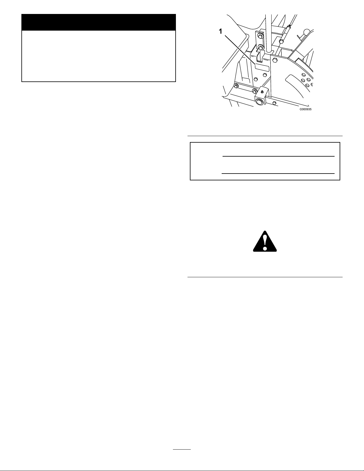
Figure1
1.Modelandserialnumberlocation
ModelNo.
SerialNo.
Thismanualidentiespotentialhazardsandhas
safetymessagesidentiedbythesafetyalertsymbol
(Figure2),whichsignalsahazardthatmaycauseserious
injuryordeathifyoudonotfollowtherecommended
precautions.
Readthisinformationcarefullytolearnhowtooperate
andmaintainyourproductproperlyandtoavoidinjury
andproductdamage.Youareresponsibleforoperating
theproductproperlyandsafely.
YoumaycontactTorodirectlyatwww .Toro.comfor
productandaccessoryinformation,helpndinga
dealer,ortoregisteryourproduct.
Wheneveryouneedservice,genuineToroparts,or
additionalinformation,contactanAuthorizedService
DealerorToroCustomerServiceandhavethemodel
andserialnumbersofyourproductready .Figure1
identiesthelocationofthemodelandserialnumbers
ontheproduct.Writethenumbersinthespace
provided.
Figure2
1.Safetyalertsymbol
Thismanualuses2otherwordstohighlightinformation.
Importantcallsattentiontospecialmechanical
informationandNoteemphasizesgeneralinformation
worthyofspecialattention.
Contents
Introduction.................................................................2
Safety...........................................................................4
SafeOperatingPractices.......................................4
SlopeChart..........................................................6
SafetyandInstructionalDecals.............................7
ProductOverview......................................................11
Controls.............................................................11
Operation...................................................................12
AddingFuel.......................................................12
CheckingtheEngineOilLevel............................13
©2007—TheToro®Company
8111LyndaleAvenueSouth
Bloomington,MN55420
Contactusatwww.Toro.com.
2
PrintedintheUSA.
AllRightsReserved
Page 3

UsingtheRolloverProtectionSystem
(ROPS)..........................................................13
ThinkSafetyFirst...............................................14
OperatingtheParkingBrake...............................15
StartingandStoppingtheEngine........................16
OperatingthePowerTakeOff(PTO).................17
TheSafetyInterlockSystem................................17
DrivingForwardorBackward.............................18
StoppingtheMachine.........................................19
AdjustingtheControlLeverResistance...............19
AdjustingtheHeight-of-Cut...............................19
AdjustingtheAnti-ScalpRollers.........................20
PositioningtheSeat............................................21
UnlatchingtheSeat.............................................21
PushingtheMachinebyHand.............................21
UsingtheSideDischarge....................................22
BreakingInaNewMachine................................22
TransportingMachines.......................................22
LoadingMachines..............................................23
OperatingTips...................................................23
Maintenance...............................................................25
RecommendedMaintenanceSchedule(s)................25
Lubrication.............................................................25
GreasingandLubrication...................................25
EngineMaintenance...............................................27
ServicingtheAirCleaner....................................27
ServicingtheEngineOil.....................................27
ServicingtheSparkPlugs....................................29
FuelSystemMaintenance.......................................30
ReplacingtheFuelFilter.....................................30
DrainingtheFuelTank.......................................31
ElectricalSystemMaintenance................................31
ServicingtheBattery...........................................31
ServicingtheFuses.............................................33
DriveSystemMaintenance.....................................33
AdjustingtheTracking........................................33
CheckingtheTirePressure.................................33
CheckingtheWheelHubSlottedNut..................34
AdjustingtheCasterPivotBearing......................34
CoolingSystemMaintenance..................................35
CleaningtheEngineScreenandtheOil
Cooler............................................................35
CleaningtheEngineFins....................................35
BrakeMaintenance.................................................35
AdjustingtheParkingBrake................................35
BeltMaintenance....................................................36
InspectingtheBelts............................................36
ReplacingtheMowerBelt...................................36
AdjustingtheMowerBeltTension......................36
CheckingandReplacingthePumpDrive
Belt................................................................37
ControlsSystemMaintenance.................................38
AdjustingtheControlHandleNeutral
Position..........................................................38
HydraulicSystemMaintenance...............................39
CheckingtheHydraulicFluid..............................39
ReplacingtheHydraulicFilterandOil.................40
BleedingtheHydraulicSystem............................41
CheckingtheHydraulicHoses............................41
SettingtheHydraulicPumpNeutral
Position..........................................................41
MowerDeckMaintenance......................................43
LevelingtheMoweratThreePositions................43
ServicingtheCuttingBlades...............................45
ReplacingtheGrassDeector.............................47
Cleaning.................................................................48
CleaningUndertheMower.................................48
WasteDisposal...................................................48
Storage.......................................................................48
Troubleshooting.........................................................50
Schematics.................................................................52
3
Page 4

Safety
•Useextracarewhenhandlinggasolineandother
fuels.Theyareammableandvaporsareexplosive.
Improperuseormaintenancebytheoperatororowner
canresultininjury.Toreducethepotentialforinjury,
complywiththesesafetyinstructionsandalwayspay
attentiontothesafetyalertsymbol,whichmeans
CAUTION,WARNING,orDANGER-“personal
safetyinstruction."Failuretocomplywiththe
instructionmayresultinpersonalinjuryordeath.
Thisproductiscapableofamputatinghandsand
feetandthrowingobjects.Alwaysfollowallsafety
instructionstoavoidseriousinjuryordeath.
Thisproductisdesignedforcuttingandrecyclinggrass
or,whenequippedwithagrassbagger,forcatching
cutgrass.Anyuseforpurposesotherthanthesecould
provedangeroustouserandbystanders.
SafeOperatingPractices
ThefollowinginstructionsarefromANSIstandard
B71.4-2004.
Training
•ReadtheOperator’sManualandothertraining
material.Iftheoperator(s)ormechanic(s)cannot
readEnglishitistheowner’ sresponsibilitytoexplain
thismaterialtothem.
•Becomefamiliarwiththesafeoperationofthe
equipment,operatorcontrols,andsafetysigns.
•Alloperatorsandmechanicsshouldbetrained.The
ownerisresponsiblefortrainingtheusers.
•Neverletchildrenoruntrainedpeopleoperateor
servicetheequipment.Localregulationsmayrestrict
theageoftheoperator.
•Theowner/usercanpreventandisresponsiblefor
accidentsorinjuriesoccurringtohimselforherself,
otherpeopleorproperty.
–Useonlyanapprovedcontainer
–Neverrefuelordrainthemachineindoors.
–Neverremovegascaporaddfuelwithengine
running.Allowenginetocoolbeforerefueling.
Donotsmoke.
•Checkthatoperator’spresencecontrols,safety
switchesandshieldsareattachedandfunctioning
properly.Donotoperateunlesstheyarefunctioning
properly.
Operation
•Neverrunanengineinanenclosedarea.
•Onlyoperateingoodlight,keepingawayfromholes
andhiddenhazards.
•Besurealldrivesareinneutralandparkingbrakeis
engagedbeforestartingengine.Starttheengineonly
fromtheoperator’sposition.Useseatbelts.
•Neverraisemowerwiththebladesrunning.
•NeveroperatewithoutthePTOshield,orother
guardssecurelyinplace.Besureallinterlocksare
attached,adjustedproperly,andfunctioningproperly.
•Neveroperatewiththedischargedeectorraised,
removedoraltered,unlessusingagrasscatcher.
•Donotchangetheenginegovernorsettingor
overspeedtheengine.
•Stoponlevelground,lowerimplements,disengage
drives,engageparkingbrake,shutoffenginebefore
leavingtheoperator’spositionforanyreason
includingemptyingthecatchersoruncloggingthe
chute.
•Stopequipmentandinspectbladesafterstriking
objectsorifanabnormalvibrationoccurs.Make
necessaryrepairsbeforeresumingoperations.
•Keephandsandfeetawayfromthecuttingunits.
Preparation
•Evaluatetheterraintodeterminewhataccessories
andattachmentsareneededtoproperlyand
safelyperformthejob.Onlyuseaccessoriesand
attachmentsapprovedbythemanufacturer.
•Wearappropriateclothingincludinghardhat,safety
glassesandhearingprotection.Longhair,loose
clothingorjewelrymaygettangledinmovingparts.
•Inspecttheareawheretheequipmentistobeused
andremoveallobjectssuchasrocks,toysandwire
whichcanbethrownbythemachine.
•Nevercarrypassengersandkeeppetsandbystanders
away.
•Bealert,slowdownandusecautionwhenmaking
turns.Lookbehindandtothesidebeforechanging
directions.
•Slowdownandusecautionwhencrossingroadsand
sidewalks.Stopbladesifnotmowing.
•Beawareofthemowerdischargedirectionanddo
notpointitatanyone.
•Donotoperatethemowerundertheinuenceof
alcoholordrugs.
4
Page 5

•Useextremecarewhenloadingorunloadingthe
machineintoatrailerortruck.
•Usecarewhenapproachingblindcorners,shrubs,
trees,orotherobjectsthatmayobscurevision.
SlopeOperation
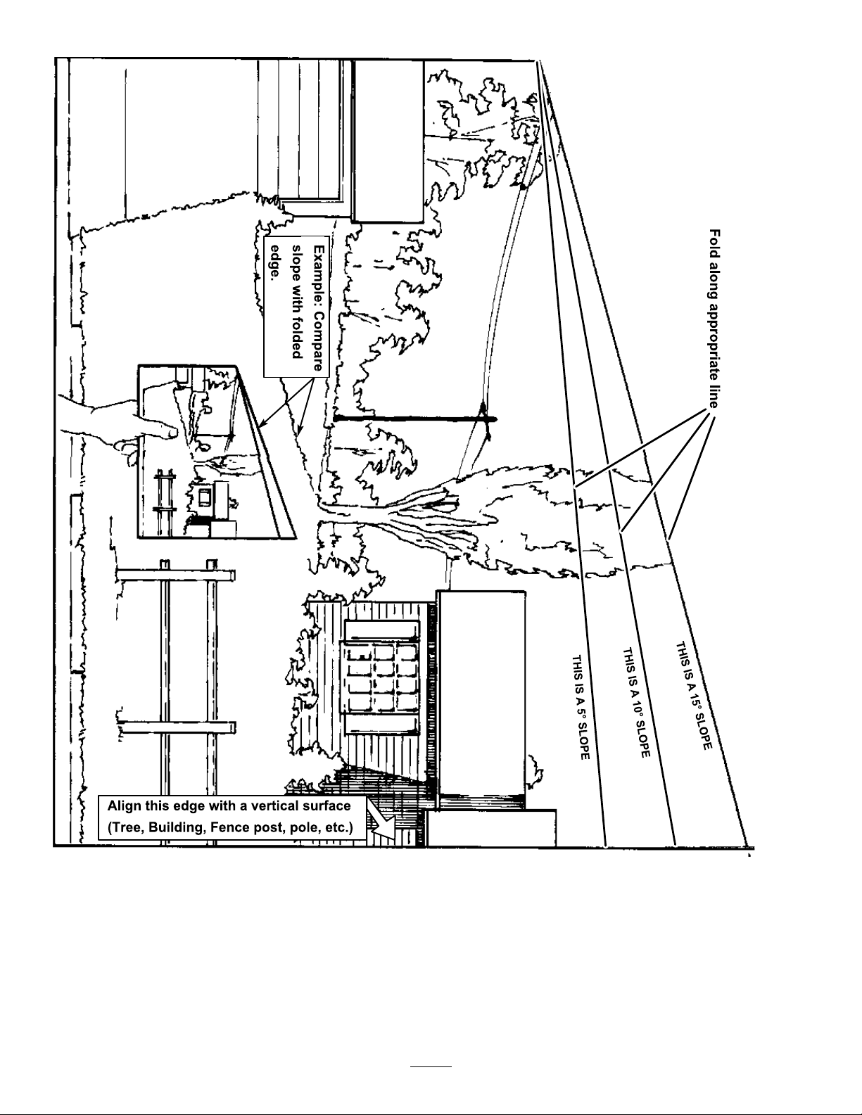
•Donotmowslopesgreaterthan15degrees.
•Donotmowneardrop-offs,ditches,steepbanks
orwater.Wheelsdroppingoveredgescancause
rollovers,whichmayresultinseriousinjury,death
ordrowning.
•Checktheareatobemowedandneverfoldthe
ROPSinareaswherethereareslopes,dropoffsor
water.
•Lowertherollbaronlywhenabsolutelynecessary.
Donotweartheseatbeltwiththerollbarfolded
down.
•Checkcarefullyforoverheadclearances(i.e.
branches,doorways,electricalwires)beforedriving
underanyobjectsanddonotcontactthem.
Maintenanceandstorage
•Donotmowslopeswhengrassiswet.Slippery
conditionsreducetractionandcouldcausesliding
andlossofcontrol.
•Donotmakesuddenturnsorrapidspeedchanges.
•Useawalkbehindmowerand/orahandtrimmer
neardrop-offs,ditches,steepbanksorwater.
•Reducespeedanduseextremecautiononslopes.
•Removeormarkobstaclessuchasrocks,treelimbs,
etc.fromthemowingarea.Tallgrasscanhide
obstacles.
•Watchforditches,holes,rocks,dips,andrisesthat
changetheoperatingangle,asroughterraincould
overturnthemachine.
•Avoidsuddenstartswhenmowinguphillbecause
themowermaytipbackwards.
•Beawarethatlossoftractionmayoccurgoing
downhill.Weighttransfertothefrontwheelsmay
causedrivewheelstoslipandcauselossofbraking
andsteering.
•Alwaysavoidsuddenstartingorstoppingona
slope.Iftireslosetraction,disengagethebladesand
proceedslowlyofftheslope.
•Followthemanufacturer’srecommendationsfor
wheelweightsorcounterweightstoimprovestability.
•Useextremecarewithgrasscatchersorother
attachments.Thesecanchangethestabilityofthe
machineandcauselossofcontrol.
•Disengagedrives,lowerimplement,setparking
brake,stopengineandremovekeyordisconnect
sparkplugwire.Waitforallmovementtostop
beforeadjusting,cleaningorrepairing.
•Cleangrassanddebrisfromcuttingunits,drives,
mufers,andenginetohelppreventres.Cleanup
oilorfuelspillage.
•Letenginecoolbeforestoringanddonotstorenear
ame.
•Shutofffuelwhilestoringortransporting.Donot
storefuelnearamesordrainindoors.
•Parkmachineonlevelground.Neverallowuntrained
personneltoservicemachine.
•Usejackstandstosupportcomponentswhen
required.
•Carefullyreleasepressurefromcomponentswith
storedenergy.
•Disconnectbatteryorremovesparkplugwirebefore
makinganyrepairs.Disconnectthenegativeterminal
rstandthepositivelast.Reconnectpositiverst
andnegativelast.
•Usecarewhencheckingblades.Wraptheblade(s)or
weargloves,andusecautionwhenservicingthem.
Onlyreplaceblades.Neverstraightenorweldthem.
•Keephandsandfeetawayfrommovingparts.If
possible,donotmakeadjustmentswiththeengine
running.
UsingtheRolloverProtectionSystem
(ROPS)
•Keeptherollbarintheraisedandlockedposition
andusetheseatbeltwhenoperatingthemachine.
•Becertainthattheseatbeltcanbereleasedquickly
intheeventofanemergency.
•Beawarethereisnorolloverprotectionwhenthe
rollbarisdown.
•Chargebatteriesinanopenwellventilatedarea,
awayfromsparkandames.Unplugchargerbefore
connectingordisconnectingfrombattery.W ear
protectiveclothinganduseinsulatedtools.
•Keepallpartsingoodworkingconditionandall
hardwaretightened.Replaceallwornordamaged
decals.
•UseonlyToroapprovedattachments.Warrantymay
bevoidedifusedwithunapprovedattachments.
5
Page 6
SlopeChart6SafetyandInstructional
Decals
Page 7
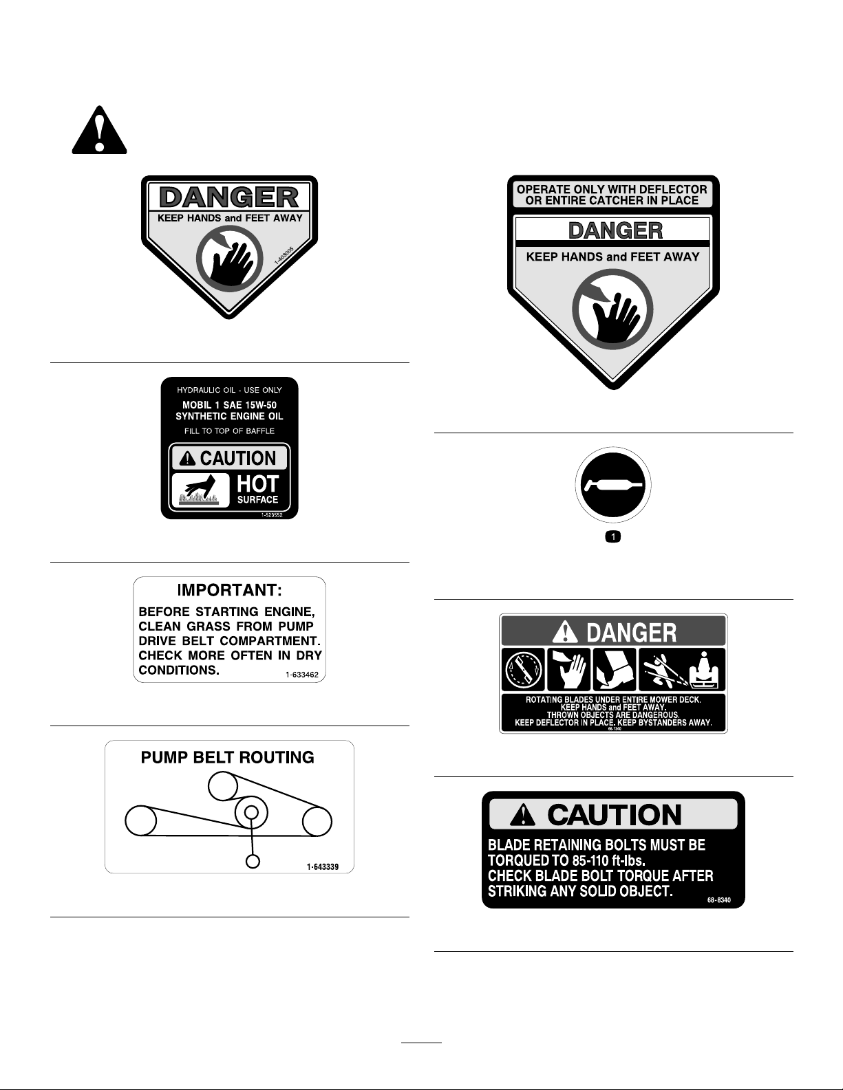
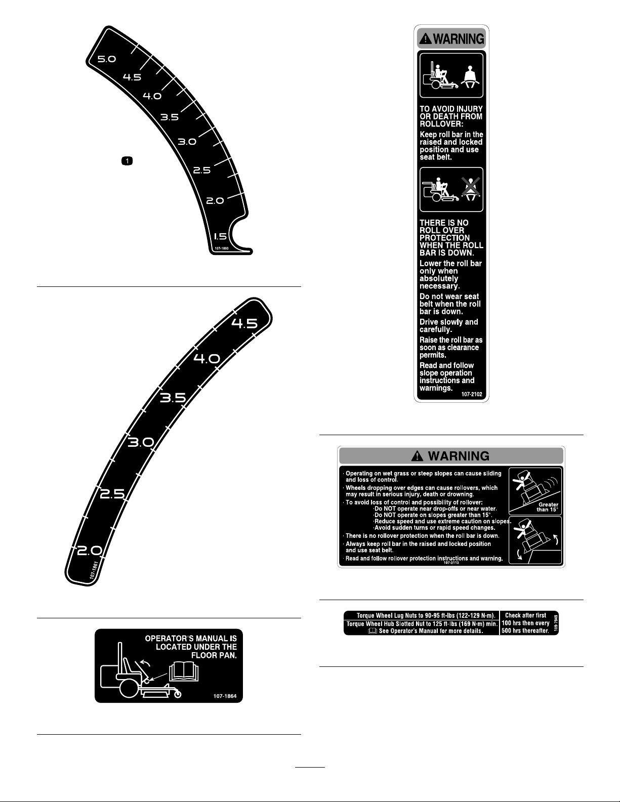
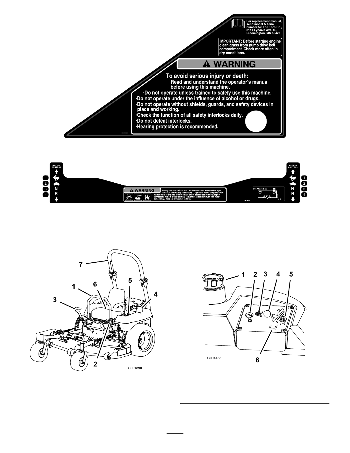
Safetydecalsandinstructionsareeasilyvisibletotheoperatorandarelocatednearanyareaof
potentialdanger.Replaceanydecalthatisdamagedorlost.
1-403005
54-9220
1-523552
58-6520
1.Grease
1-633462
66-1340
1-643339
68-8340
7
Page 8
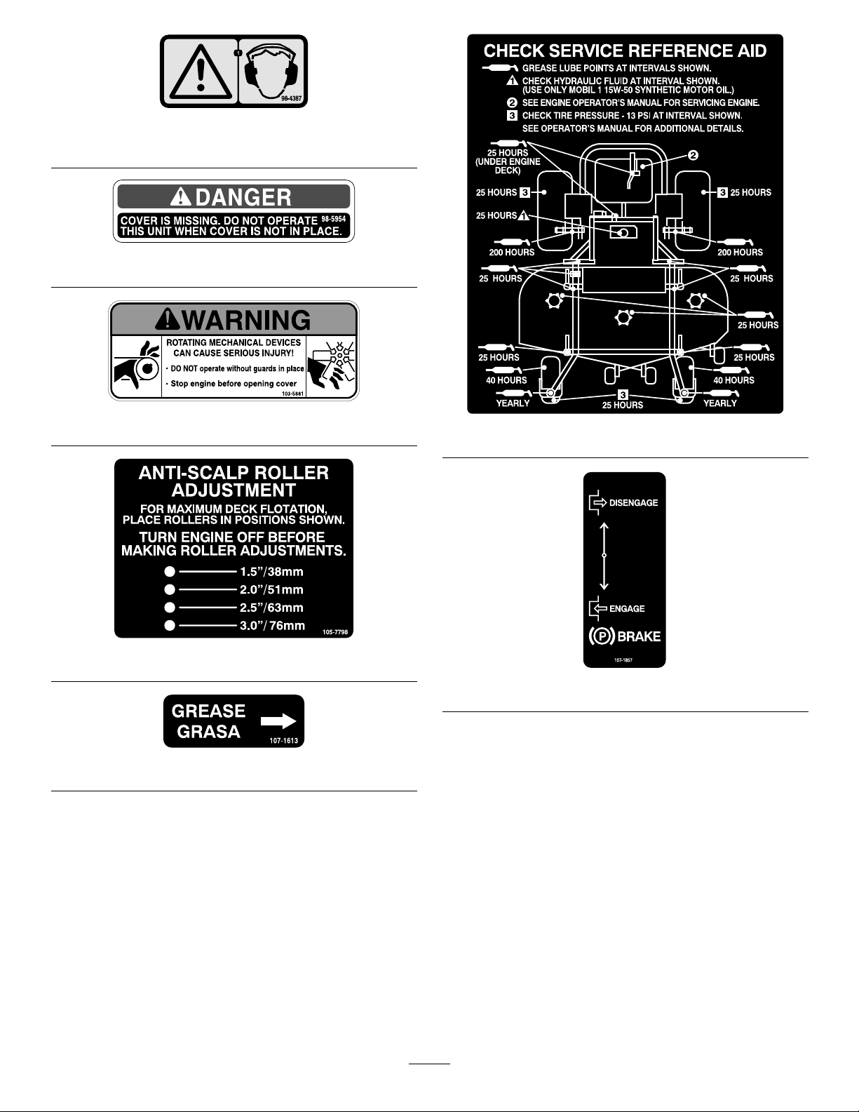
1.Warning—wearhearingprotection.
98-4387
98-5954
103-5881
107-1621
105-7798
107-1857
107-1613
8
Page 9
107-1860
107-2102
107-2112
107-1861
109-7949
107-1864
9
Page 10
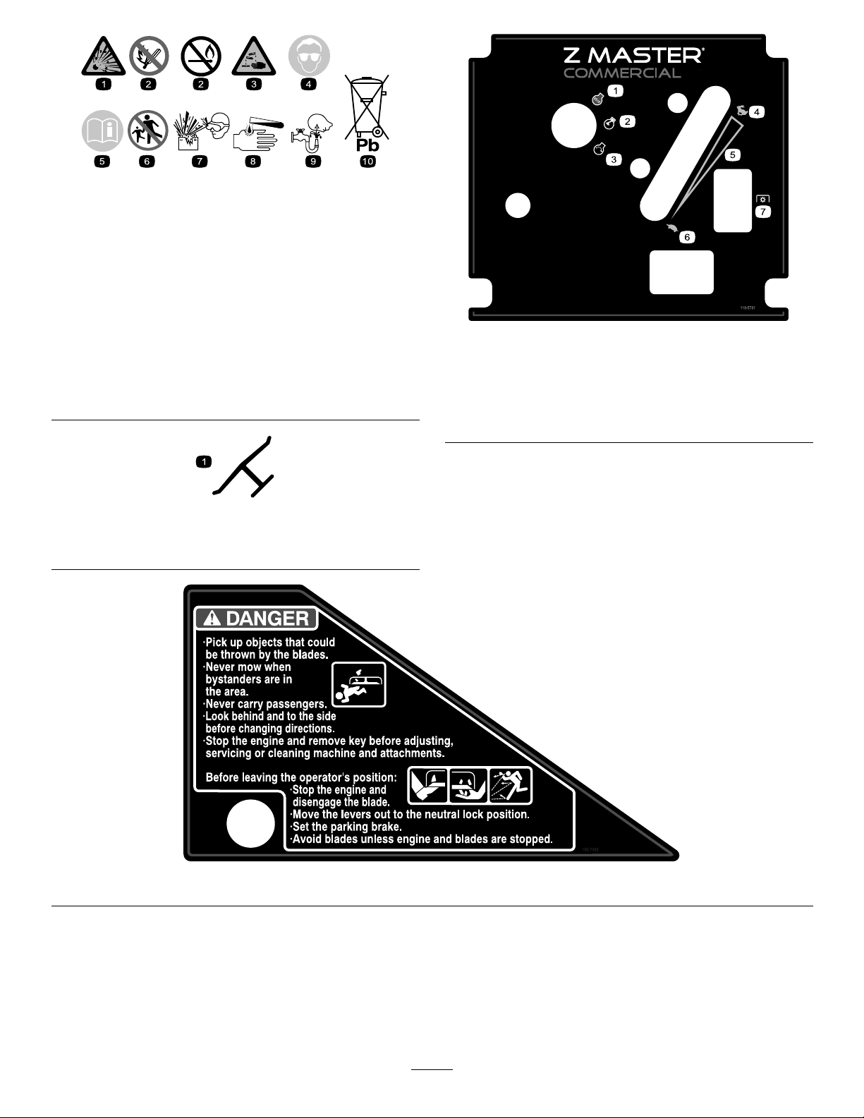
BatterySymbols
Someorallofthesesymbolsareonyourbattery
1.Explosionhazard
2.Nore,opename,or
smoking.
3.Causticliquid/chemical
burnhazard
4.Weareyeprotection9.Flusheyesimmediately
5.ReadtheOperator’s
Manual.
6.Keepbystandersasafe
distancefromthebattery.
7.Weareyeprotection;
explosivegasescan
causeblindnessandother
injuries
8.Batteryacidcancause
blindnessorsevereburns.
withwaterandgetmedical
helpfast.
10.Containslead;donot
discard.
Manufacturer’sMark
1.Indicatesthebladeisidentiedasapartfromtheoriginal
machinemanufacturer.
110-5731
1.Engine—stop
2.Engine—run
3.Engine—start
4.Fast
5.Continuousvariable
setting
6.Slow
7.Powertake-off(PTO)
106-7492
10
Page 11
106-9989
107-8076
1.Fast
2.Slow
3.Neutral4.Reverse
ProductOverview
1.Motioncontrollever
2.Parkingbrakelever
3.Height-of-cutlever
4.Fuelcap(bothsides)
Figure3
5.Controls
6.Seatbelt
7.Rollbar
Controls
Becomefamiliarwithallthecontrolsbeforeyoustartthe
engineandoperatethemachine(Figure3andFigure4).
Figure4
1.Gascap
2.Choke5.Powertakeoff(PTO)
3.Ignitionswitch6.Hourmeter
4.Throttle
11
Page 12

HourMeter
Thehourmeterrecordsthenumberofhourstheengine
hasoperated.Itoperateswhentheengineisrunning.
Usethesetimesforschedulingregularmaintenance
(Figure4).
ThrottleControl
Thethrottlecontrolhastwopositions:FastandSlow.
Choke
Operation
Note:Determinetheleftandrightsidesofthe
machinefromthenormaloperatingposition.
AddingFuel
UseUnleadedRegularGasolinesuitablefor
automotiveuse(85pumpoctaneminimum).Leaded
regulargasolinemaybeusedifunleadedregularisnot
available.
Usethechoketostartacoldengine.
BladeControlSwitch(PTO)
Thebladecontrolswitch(PTO)isusedtoengagethe
electricclutchtodrivethemowerbladeswiththemotion
controlleversinthecenter,un-lockedposition.Pullthe
switchuptoengagethebladesandrelease.Todisengage
theblades,pushthebladecontrolswitch(PTO)down.
IgnitionSwitch
Thisswitchisusedtostartthemowerengineandhas
threepositions:Start,RunandOff.
Attachments/Accessories
AselectionofToroapprovedattachmentsand
accessoriesareavailableforusewiththemachineto
enhanceandexpanditscapabilities.Contactyour
AuthorizedServiceDealerorDistributororgoto
www.Toro.comforalistofallapprovedattachments
andaccessories.
Important:Neverusemethanol,gasoline
containingmethanol,orgasoholcontainingmore
than10%ethanolbecausethefuelsystemcouldbe
damaged.Donotmixoilwithgasoline.
Incertainconditions,gasolineisextremely
ammableandhighlyexplosive.Areor
explosionfromgasolinecanburnyouand
othersandcandamageproperty.
•Fillthefueltankoutdoors,inanopenarea,
whentheengineiscold.Wipeupany
gasolinethatspills.
•Neverllthefueltankinsideanenclosed
trailer.
•Donotllthefueltankcompletelyfull.Add
gasolinetothefueltankuntilthelevelis1/4
to1/2inch(6to13mm)belowthebottomof
thellerneck.Thisemptyspaceinthetank
allowsgasolinetoexpand.
•Neversmokewhenhandlinggasoline,and
stayawayfromanopenameorwhere
gasolinefumesmaybeignitedbyaspark.
•Storegasolineinanapprovedcontainerand
keepitoutofthereachofchildren.Never
buymorethana30-daysupplyofgasoline.
•Donotoperatewithoutentireexhaust
systeminplaceandinproperworking
condition.
12
Page 13

Important:Donotusefueladditivescontaining
methanolorethanol.
Incertainconditionsduringfueling,static
electricitycanbereleasedcausingaspark
whichcanignitethegasolinevapors.Are
orexplosionfromgasolinecanburnyouand
othersandcandamageproperty.
•Alwaysplacegasolinecontainersonthe
groundawayfromyourvehiclebeforelling.
•Donotllgasolinecontainersinsidea
vehicleoronatruckortrailerbedbecause
interiorcarpetsorplastictruckbedliners
mayinsulatethecontainerandslowtheloss
ofanystaticcharge.
•Whenpractical,removegas-powered
equipmentfromthetruckortrailerand
refueltheequipmentwithitswheelsonthe
ground.
•Ifthisisnotpossible,thenrefuelsuch
equipmentonatruckortrailerfroma
portablecontainer,ratherthanfroma
gasolinedispensernozzle.
Addthecorrectamountofgasstabilizer/conditioner
tothegas.
Note:Afuelstabilizer/conditionerismosteffective
whenmixedwithfreshgasoline.Tominimizethe
chanceofvarnishdepositsinthefuelsystem,usefuel
stabilizeratalltimes.
FillingtheFuelTank
1.Shuttheengineoffandsettheparkingbrake.
2.Cleanaroundeachfueltankcapandremovethecap.
3.Addunleadedregulargasolinetobothfueltanks,
untilthelevelis1/4to1/2inch(6mmto13mm)
belowthebottomofthellerneck.
Thisspaceinthetankallowsgasolinetoexpand.
Donotllthefueltankscompletelyfull.
4.Installfueltankcapssecurely.
5.Wipeupanygasolinethatmayhavespilled.
•Ifagasolinedispensernozzlemustbeused,
keepthenozzleincontactwiththerimof
thefueltankorcontaineropeningatall
timesuntilfuelingiscomplete.
Gasolineisharmfulorfatalifswallowed.
Long-termexposuretovaporscancauseserious
injuryandillness.
•Avoidprolongedbreathingofvapors.
•Keepfaceawayfromnozzleandgastankor
conditioneropening.
•Keepgasawayfromeyesandskin.
UsingStabilizer/Conditioner
Useafuelstabilizer/conditionerinthemachineto
providethefollowingbenets:
CheckingtheEngineOilLevel
Beforeyoustarttheengineandusethemachine,check
theoillevelintheenginecrankcase;refertoChecking
theOilLevelinEngineMaintenance,page27
UsingtheRolloverProtection
System(ROPS)
Toavoidinjuryordeathfromrollover:keepthe
rollbarintheraisedlockedpositionanduse
theseatbelt.
Ensurethattherearpartoftheseatissecured
withtheseatlatch.
•Keepsgasolinefreshduringstorageof90daysor
less.Forlongerstorageitisrecommendedthatthe
fueltankbedrained.
•Cleanstheenginewhileitruns
•Eliminatesgum-likevarnishbuildupinthefuel
system,whichcauseshardstarting
13
Page 14
Thereisnorolloverprotectionwhentherollbar
G004955
1
2
3
4
isinthedownposition.
•Lowertherollbaronlywhenabsolutely
necessary.
•Donotweartheseatbeltwhentherollbaris
inthedownposition.
•Driveslowlyandcarefully.
•Raisetherollbarassoonasclearance
permits.
•Checkcarefullyforoverheadclearances(i.e.
branches,doorways,electricalwires)before
drivingunderanyobjectsanddonotcontact
them.
Important:Lowertherollbaronlywhen
absolutelynecessary.
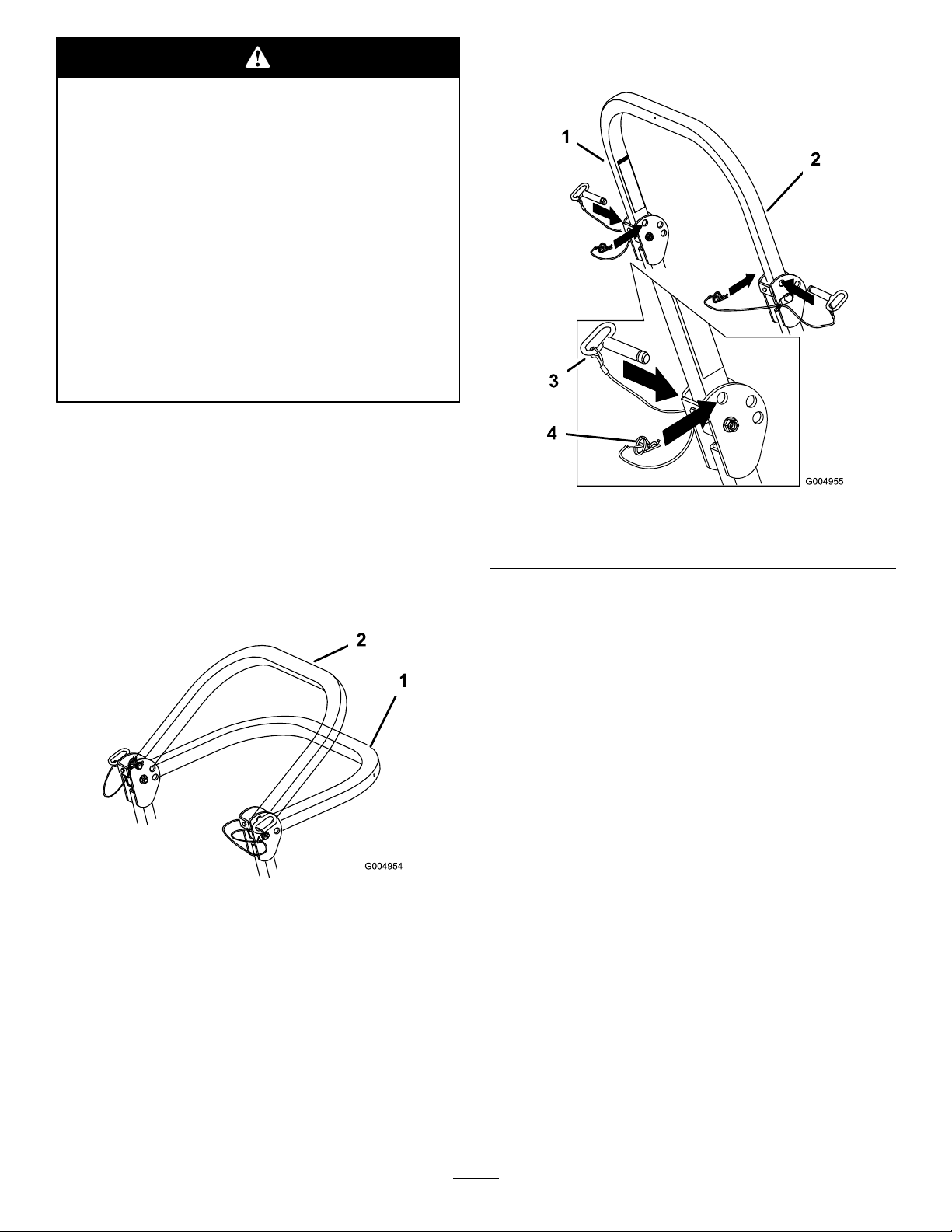
1.Removethehairpincotterpinsandremovethetwo
pins(Figure6).
2.Lowertherollbartothedownposition.Thereare
twodownpositions.SeeFigure5forthepositions.
Important:Alwaysusetheseatbeltwiththe
rollbarintheraisedposition.
Figure6
1.Rollbar3.Pin
2.Raisedposition4.Hairpincotterpin
3.Installthetwopinsandsecurethemwiththe
hairpincotterpins(Figure6).
1.Fulldownposition2.Downpositionwithbagger
Figure5
Important:Ensurethattherearpartofthe
seatissecuredwiththeseatlatch.
ThinkSafetyFirst
Pleasereadallsafetyinstructionsandsymbolsinthe
safetysection.Knowingthisinformationcouldhelp
youorbystandersavoidinjury.
installed
4.Toraisetherollbar,removethehairpincotterpins
andremovethetwopins(Figure6).
5.Raisetherollbartotheuprightpositionandinstall
thetwopinsandsecurethemwiththehairpincotter
pins(Figure6).
14
Page 15
Operatingonwetgrassorsteepslopescan
causeslidingandlossofcontrol.
Wheelsdroppingoveredgescancauserollovers,
whichmayresultinseriousinjury,deathor
drowning.
Thereisnorolloverprotectionwhentheroll
barisdown.
Alwayskeeptherollbarintheraisedandlocked
positionandusetheseatbelt.
Readandfollowtherolloverprotection
instructionsandwarnings.
Toavoidlossofcontrolandpossibilityof
rollover:
Thismachineproducessoundlevelsinexcess
of85dBAattheoperatorsearandcancause
hearinglossthroughextendedperiodsof
exposure.
Wearhearingprotectionwhenoperatingthis
machine.
Theuseofprotectiveequipmentforeyes,ears,feetand
headisrecommended.
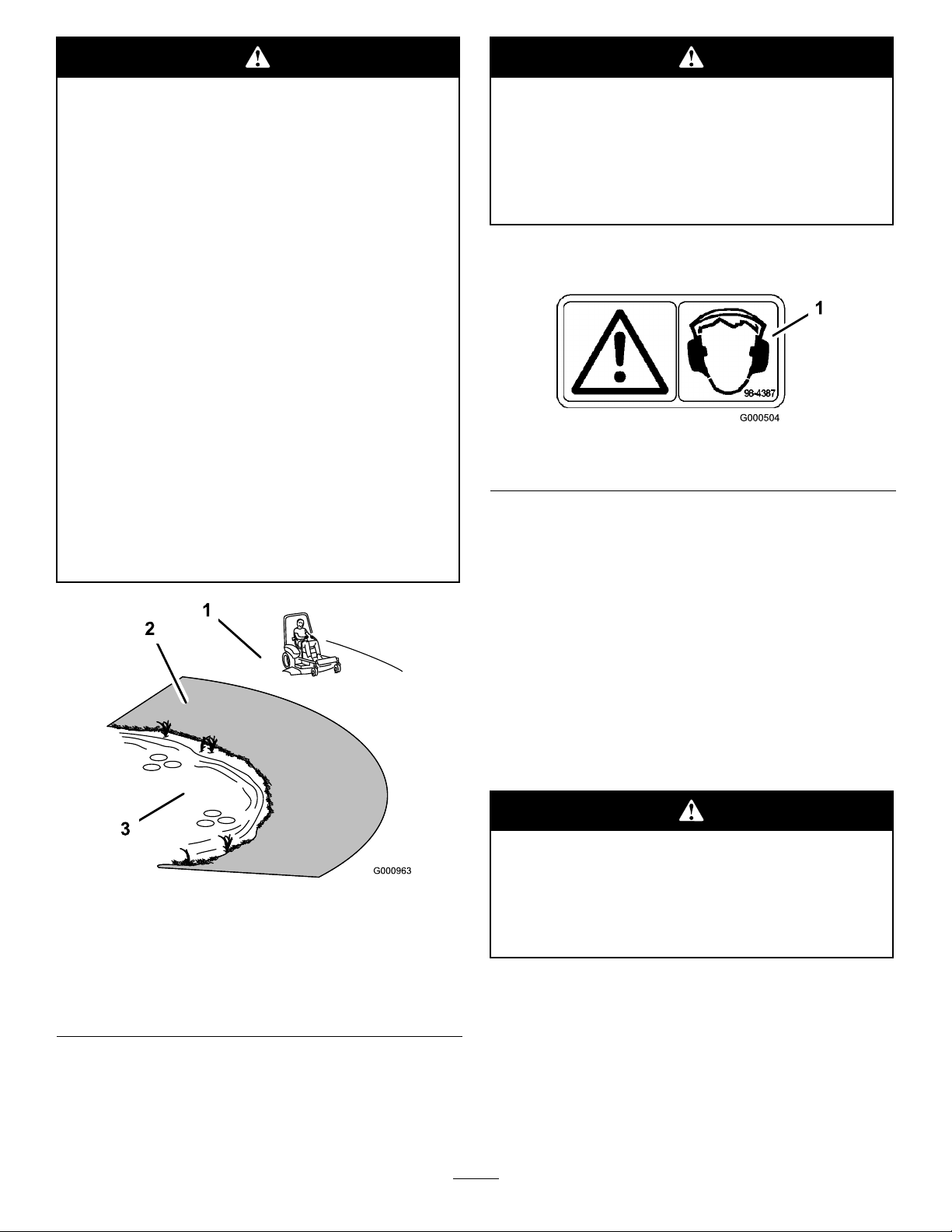
•Donotoperateneardrop-offsornearwater.
•Donotoperateonslopesgreaterthan
15degrees.
•Reducespeedanduseextremecautionon
slopes.
•Avoidsuddenturnsorrapidspeedchanges.
Figure7
1.SafeZone-usethe
ZMasterhereonslopes
lessthan15degreesor
atareas.
2.Usewalkbehindmower
and/orhandtrimmernear
drop-offsandwater.
3.Water
Figure8
1.Warning—wearhearingprotection
OperatingtheParkingBrake
Alwayssettheparkingbrakewhenyoustopthe
machineorleaveitunattended.
SettingtheParkingBrake
1.Movethemotioncontrollevers(Figure15)outto
theneutrallockposition.
2.Pullupandbackontheparkingbrakelevertoset
theparkingbrake(Figure9).Theparkingbrake
levershouldstayrmlyintheengagedposition.
Parkingbrakemaynotholdmachineparked
onaslopeandcouldcausepersonalinjuryor
propertydamage.
Donotparkonslopesunlesswheelsare
chockedorblocked
ReleasingtheParkingBrake
Pushforwardanddownontheparkingbrakelever
toreleasetheparkingbrake(Figure9).Theparking
brakeisdisengagedandtheleverwillrestagainstthe
brakestop.
15
Page 16
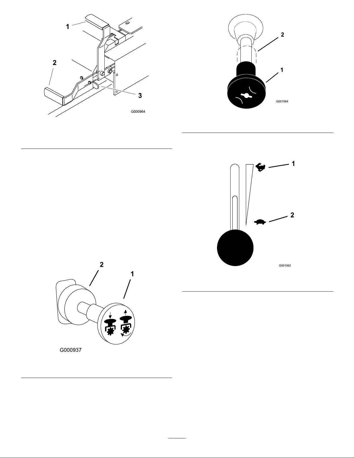
Figure9
1.Parkingbrake-ON3.BrakeStop
2.Parkingbrake-OFF
StartingandStoppingthe
Engine
StartingtheEngine
1.Sitontheseatandmovethemotioncontrolsto
neutrallockedposition.
2.Settheparkingbrake;refertoSettingtheParking
Brake.
3.MovethePTO(powertakeoff)switchtotheOff
position(Figure10).
Figure11
1.Choke—on2.Choke—off
5.MovethethrottlecontroltotheFastposition
beforestartingacoldengine(Figure12).
Figure12
1.Throttle—fast
2.Throttle—slow
Figure10
1.PTO—on2.PTO—off
4.Movethechokecontroltotheonpositionbefore
startingacoldengine(Figure11).
Note:Awarmorhotenginemaynotrequire
choking.Afterenginestarts,movechokecontrolto
Runposition.
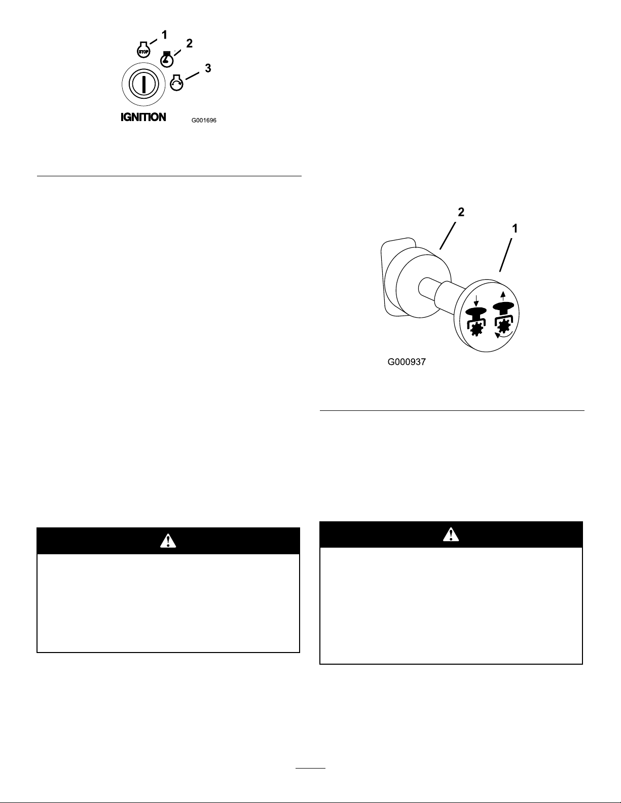
6.TurntheignitionkeytoStart(Figure13).Whenthe
enginesstarts,releasethekey.
Important:Donotengagestarterformore
than10secondsatatime.Ifenginefailstostart,
allow30secondcool-downperiodbetween
attempts.Failuretofollowtheseinstructions
canburnoutstartermotor.
16
Page 17
EngagingthePTO
1.Iftheengineiscold,allowtheenginetowarmup5
to10minutesbeforeengagingthePTO.
2.Whileseatedintheseat,releasethepressureonthe
tractioncontrolleversandplaceinneutral.
3.Placethethrottleinthefastposition.
Figure13
1.Off3.Start
2.Run
7.Aftertheenginestarts,movethechoketooff
(Figure11).Iftheenginestallsorhesitates,move
thechokebacktoonforafewseconds,thenmove
thethrottlelevertodesiredsetting.Repeatthisas
required.
StoppingtheEngine
1.PushthePTOtotheoffposition(Figure10).
2.Movethethrottlelevermidwaybetweentheslow
andfastpositions(Figure12).
3.Lettheengineidlefor60seconds.
4.Turntheignitionkeytotheoffpositionandremove
thekey(Figure13).
5.Closethefuelshutoffvalvebeforetransporting
orstoringthemachine.RefertoFuelSystem
Maintenance,page30.
Important:Makesurethatthefuelshutoff
valveisclosedbeforetransportingorstoring
themachine,asfuelleakagemayoccur.Setthe
parkingbrakebeforetransporting.Makesure
toremovethekeyasthefuelpumpmayrun
andcausethebatterytolosecharge.
Note:EngagingthePTOwiththethrottleatthe
halforlesspositionwillcauseexcessiveweartothe
drivebelts.
4.Pulloutonthepowertakeoff(PTO)switchto
engageit(Figure14).
Figure14
1.PTO-On2.PTO-Off
DisengagingthePTO
Todisengage,pushthePTOswitchtotheoffposition
(Figure14).
TheSafetyInterlockSystem
Childrenorbystandersmaybeinjuredifthey
moveorattempttooperatethetractorwhileit
isunattended.
Alwaysremovetheignitionkeyandsetthe
parkingbrakewhenleavingthemachine
unattended,evenifjustforafewminutes.
OperatingthePowerTakeOff
(PTO)
Thepowertakeoff(PTO)switchstartsandstopsthe
mowerbladesandanypoweredattachments.
Ifsafetyinterlockswitchesaredisconnected
ordamagedthemachinecouldoperate
unexpectedlycausingpersonalinjury.
•Donottamperwiththeinterlockswitches.
•Checktheoperationoftheinterlock
switchesdailyandreplaceanydamaged
switchesbeforeoperatingthemachine.
UnderstandingtheSafetyInterlock
System
Thesafetyinterlocksystemisdesignedtopreventthe
enginefromstartingunless:
17
Page 18

•Youaresittingontheseat.
•Theparkingbrakeisengaged.
•Thepowertakeoff(PTO)isdisengaged.
•Themotioncontrolleversareintheneutrallocked
position
Thesafetyinterlocksystemalsoisdesignedtostopthe
enginewhenthetractioncontrolsaremovedfromthe
lockedpositionwiththeparkingbrakeengagedorif
yourisefromtheseatwhenthePTOisengaged.
TestingtheSafetyInterlockSystem
ServiceInterval:Beforeeachuseordaily
Testthesafetyinterlocksystembeforeyouusethe
machineeachtime.Ifthesafetysystemdoesnot
operateasdescribedbelow ,haveanAuthorizedService
Dealerrepairthesafetysystemimmediately .
1.Sittingontheseat,engagetheparkingbrakeand
movethePTOtoon.Trystartingtheengine;the
engineshouldnotcrank.
2.Sittingontheseat,engagetheparkingbrakeand
movethePTOtooff.Moveeithermotioncontrol
lever(outofneutrallockedposition).Trystarting
theengine;theengineshouldnotcrank.Repeatfor
othercontrollever.
3.Sittingontheseat,engagetheparkingbrake,
movethePTOswitchtooffandmovethemotion
controlleverstoneutrallockposition.Nowstart
theengine.Whiletheengineisrunning,release
theparkingbrake,engagethePTOandriseslightly
fromtheseat;theengineshouldstop.
Machinecanspinveryrapidly .Operatormay
losecontrolofmachineandcausepersonal
injuryordamagetomachine.
•Usecautionwhenmakingturns.
•Slowthemachinedownbeforemaking
sharpturns.
DrivingForward
1.Releasetheparkingbrake;refertoReleasingthe
ParkingBrake.
2.Movetheleverstothecenter,un-lockedposition.
3.Togoforward,slowlypushthemotioncontrol
leversforward(Figure15).
Note:Theenginewillkillifthetractioncontrol
leversaremovedwiththeparkingbrakeengaged.
Togostraight,applyequalpressuretobothmotion
controllevers(Figure15).
Toturn,movethemotioncontrollevertoward
neutralinthedirectionyouwanttoturn(Figure15).
Thefartheryoumovethetractioncontrolleversin
eitherdirection,thefasterthemachinewillmovein
thatdirection.
Tostop,pullthemotioncontrolleverstotheneutral
position.
4.Sittingontheseat,engagetheparkingbrake,move
thePTOswitchtooffandmovethemotioncontrol
leverstoneutrallockposition.Nowstarttheengine.
Whiletheengineisrunning,centereithermotion
controlandmove(forwardorreverse);theengine
shouldstop.Repeatforothermotioncontrol.
5.Sittingontheseat,disengagetheparkingbrake,
movethePTOswitchtooffandmovethemotion
controlleverstoneutrallockposition.Trystarting
theengine;theengineshouldnotcrank.
DrivingForwardorBackward
Thethrottlecontrolregulatestheenginespeedas
measuredinrpm(revolutionsperminute).Place
thethrottlecontrolinthefastpositionforbest
performance.Alwaysoperateinthefullthrottle
positionwhenmowing.
18
Page 19
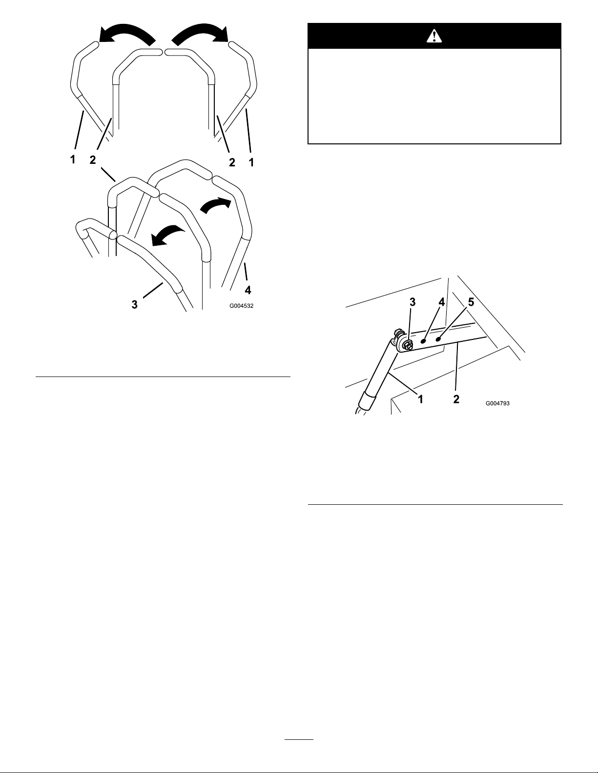
1.Motioncontrol
lever-neutrallockposition
2.Centerun-lockposition
Childrenorbystandersmaybeinjuredifthey
moveorattempttooperatethetractorwhileit
isunattended.
Alwaysremovetheignitionkeyandsetthe
parkingbrakewhenleavingthemachine
unattended,evenifjustforafewminutes.
AdjustingtheControlLever
Resistance
Thetopdampermountingboltcanbeadjustedto
obtainadesiredmotioncontrolleverresistance.Refer
toFigure16forthemountingoptions.
Torquetheboltto200in-lb(22.6N⋅m).
Figure15
3.Forward
4.Backward
DrivingBackward
1.Movetheleverstothecenter,un-lockedposition.
2.Togobackward,slowlypullthemotioncontrol
leversrearward(Figure15).
Togostraight,applyequalpressuretobothmotion
controllevers(Figure15).
Toturn,releasepressureonthemotioncontrollever
towardthedirectionyouwanttoturn(Figure15).
Tostop,pushthemotioncontrolleverstothe
neutralposition.
StoppingtheMachine
Tostopthemachine,movethetractioncontrollevers
toneutralandmovetolockedposition,disengagethe
powertakeoff(PTO),andturntheignitionkeytooff.
Settheparkingbrakewhenyouleavethemachine;refer
toSettingtheParkingBrake.Remembertoremovethe
keyfromtheignitionswitch.
Figure16
1.Damper4.Mediumresistanceor
2.Motioncontrolbracket
3.Mostresistanceorrmest
feel
mediumfeel
5.Leastresistanceorsoftest
feel
AdjustingtheHeight-of-Cut
Theheight-of-cutisadjustedfrom1-1/2to5inch
(38to127mm)in1/4inch(6mm)incrementsby
relocatingtheclevispinintodifferentholelocations.
1.Raisetheheight-of-cutlevertothetransport
position(alsothe5inch(127mm)cuttingheight
position)(Figure17).
19
Page 20
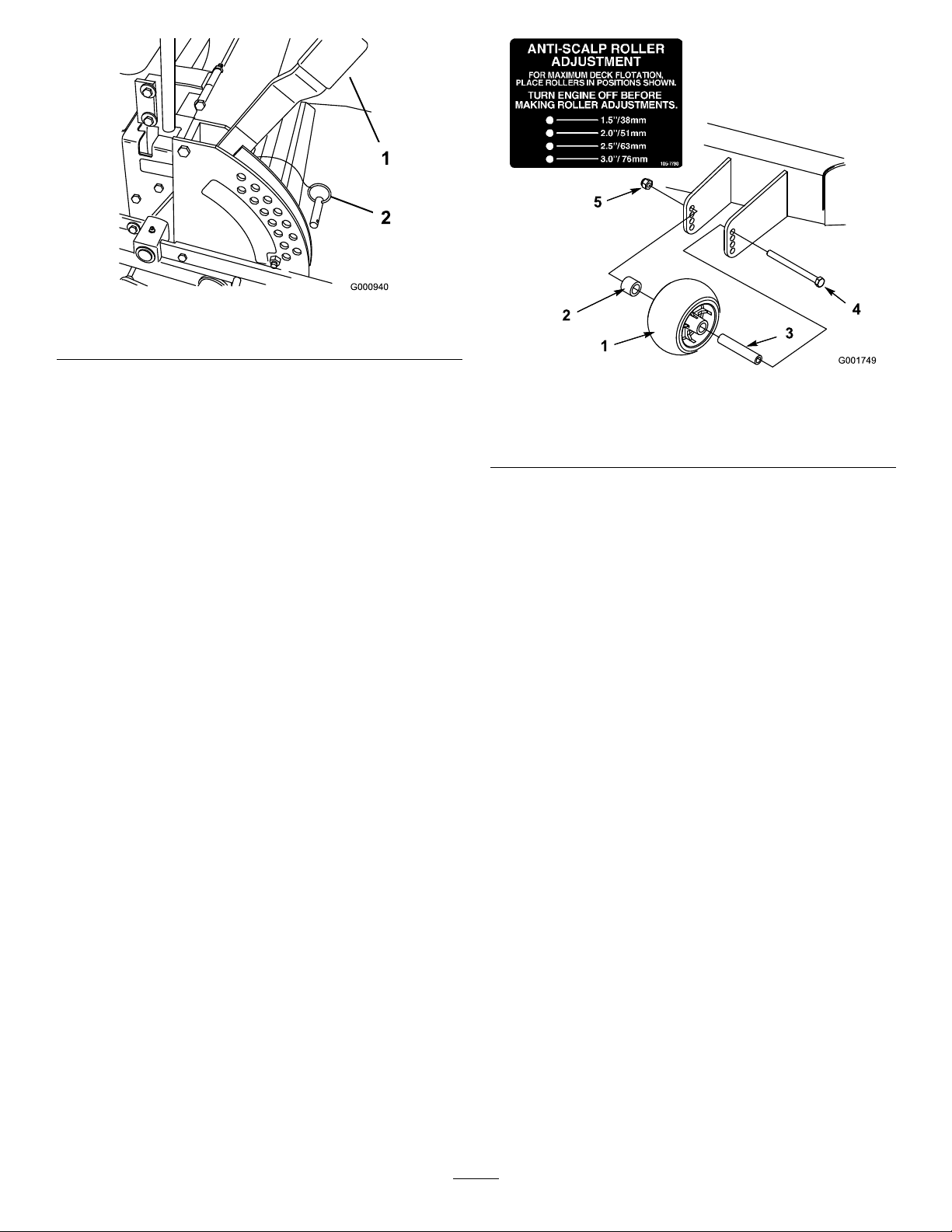
Figure17
1.Heightofcutlever2.ClevisPin
2.Toadjust,removetheclevispinfromthe
height-of-cutbracket(Figure17).
3.Selectaholeintheheight-of-cutbracket
correspondingtotheheight-of-cutdesiredand,
inserttheclevispin(Figure17).
4.Movethelevertotheselectedheight.
AdjustingtheAnti-Scalp
Rollers
Wheneveryouchangetheheight-of-cut,itis
recommendedtoadjusttheheightoftheanti-scalp
rollers.
AdjustingtheOuterRoller
1.DisengagethePTO,movethemotioncontrol
leverstotheneutrallockedposition,andsetthe
parkingbrake.
2.Stoptheengine,removethekey ,andwaitforall
movingpartstostopbeforeleavingtheoperating
position.
Figure18
1.Outerroller
2.Spacer
3.Bushing
4.Bolt
5.Nut
4.Selectaholesothattheouterrollerispositioned
tothenearestcorrespondingheight-of-cutdesired
(Figure18).
5.Installtheouterroller,bushing,spacer,bolt,and
nut(Figure18).
6.Torquetheboltto40to45ft-lb(54to61N⋅m).
AdjustingtheCenterRollers
1.DisengagethePTO,movethemotioncontrol
leverstotheneutrallockedposition,andsetthe
parkingbrake.
2.Stoptheengine,removethekey ,andwaitforall
movingpartstostopbeforeleavingtheoperating
position.
3.Afteradjustingtheheight-of-cut,removetheange
nut,bushing,andbolt(Figure19).
3.Afteradjustingtheheight-of-cut,removetheange
nut,bushing,spacer,andbolt(Figure18).
20
Page 21
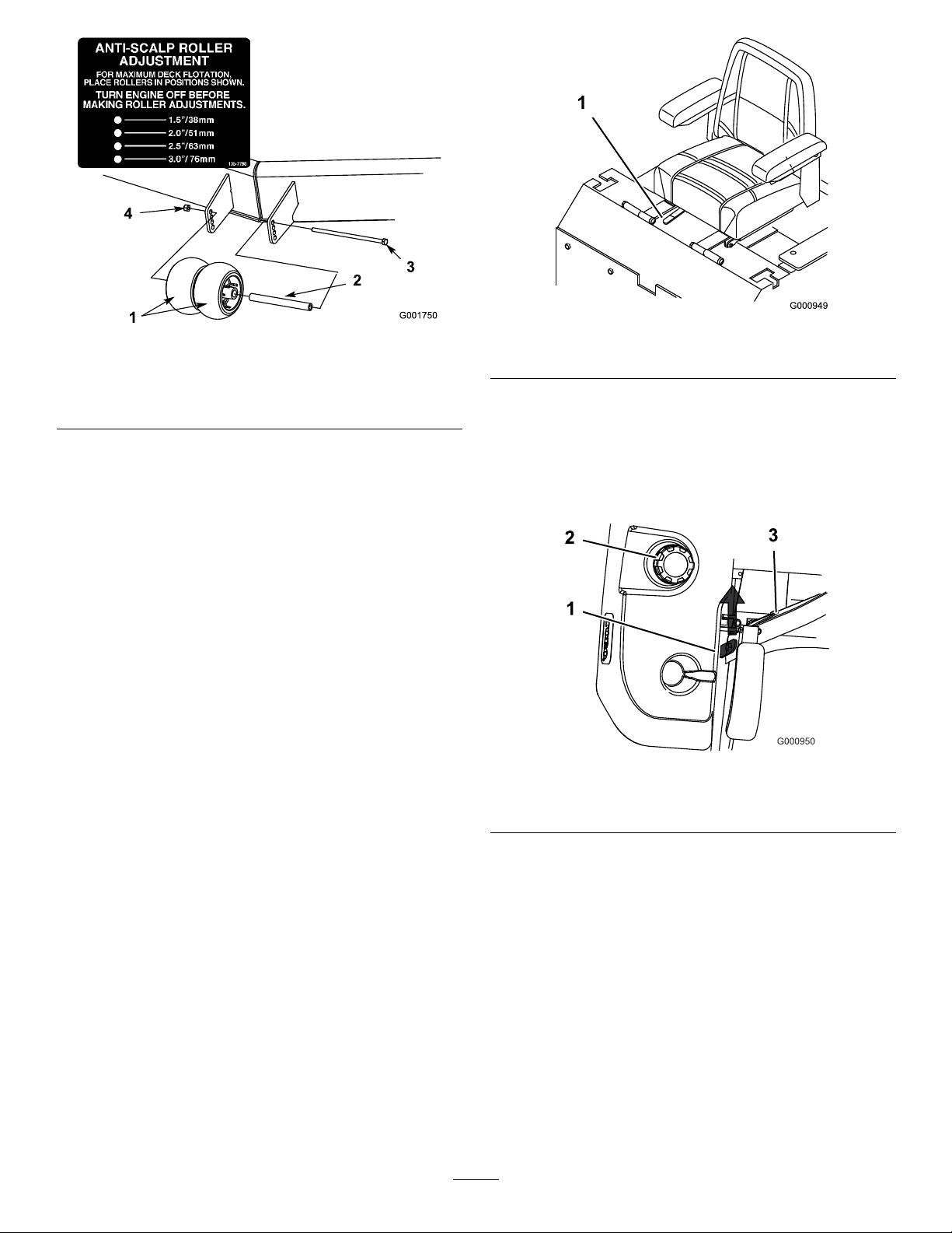
1.Outerroller
2.Spacer
3.Bushing
Figure19
Figure20
1.Adjustmentlever
4.Bolt
5.Nut
UnlatchingtheSeat
4.Selectaholesothatthecenterrollersarepositioned
tothenearestcorrespondingheight-of-cutdesired
(Figure19).
Note:Donotadjusttherollerstosupportthe
mowerhousing.
5.Installthecenterrollers,bushing,spacer,bolt,and
nut(Figure19).
6.Torquetheboltto40to45ft-lb(54to61N⋅m).
PositioningtheSeat
Theseatcanmoveforwardandbackward.Positionthe
seatwhereyouhavethebestcontrolofthemachine
andaremostcomfortable.
Important:T oadjust,movetheleversidewaysto
unlockseat(Figure20).
Slidetheseattothedesiredpositionandreleaselever
tolockinposition.
Pushtheseatlatchrearwardtounlatchtheseat.
Thiswillallowaccesstothemachineundertheseat
(Figure21).
Figure21
1.Seatlatch3.Seat
2.Fuelcap
PushingtheMachinebyHand
Important:Alwayspushthemachinebyhand.
Nevertowthemachinebecausehydraulicdamage
mayoccur.
PushingtheMachine
1.Disengagethepowertakeoff(PTO)andturnthe
ignitionkeytooff.Movetheleverstoneutrallocked
positionandapplyparkingbrake.Removethekey.
2.Rotatetheby-passvalvescounterclockwise1turn
topush.Thisallowshydraulicuidtoby-passthe
pumpenablingthewheelstoturn(Figure22).
21
Page 22
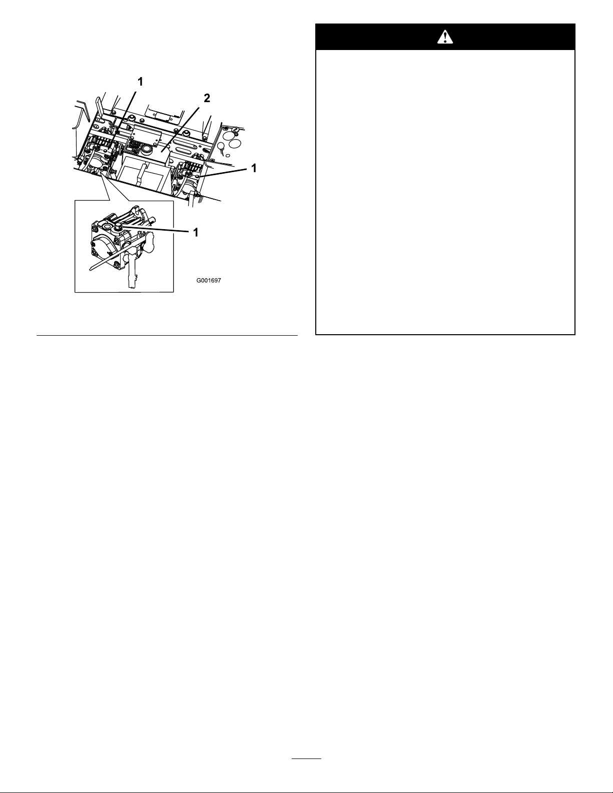
Important:Donotrotateby-passvalvesmore
than1turn.Thispreventsvalvesfromcoming
outofthebodyandcausinguidtorunout.
Figure22
1.By-passvalve2.Hydraulictank
Withoutthegrassdeector,dischargecover,
orcompletegrasscatcherassemblymounted
inplace,youandothersareexposedtoblade
contactandthrowndebris.Contactwith
rotatingmowerblade(s)andthrowndebriswill
causeinjuryordeath.
•Neverremovethegrassdeectorfrom
themowerbecausethegrassdeector
routesmaterialdowntowardtheturf.Ifthe
grassdeectoriseverdamaged,replaceit
immediately.
•Neverputyourhandsorfeetunderthe
mower.
•Nevertrytoclearthedischargeareaor
mowerbladesunlessyoumovethepower
takeoff(PTO)totheoffposition,rotatethe
ignitionkeytooffandremovethekey.
•Makesurethegrassdeectorisinthedown
position.
3.Disengageparkingbrakebeforepushing.
ChangingtoMachineOperation
Rotatetheby-passvalvesclockwise1turntooperate
machine(Figure22).
Note:Donotovertightentheby-passvalves.
Themachinewillnotdriveunlessby-passvalvesare
turnedin.
UsingtheSideDischarge
Themowerhasahingedgrassdeectorthatdisperses
clippingstothesideanddowntowardtheturf.
BreakingInaNewMachine
Newenginestaketimetodevelopfullpower.Mower
decksanddrivesystemshavehigherfrictionwhennew,
placingadditionalloadontheengine.Allow40to50
hoursofbreak-intimefornewmachinestodevelopfull
powerandbestperformance.
TransportingMachines
Useaheavy-dutytrailerortrucktotransportthe
machine.Ensurethatthetrailerortruckhasall
necessarylightingandmarkingasrequiredbylaw .
Pleasecarefullyreadallthesafetyinstructions.
Knowingthisinformationcouldhelpyou,yourfamily ,
petsorbystandersavoidinjury.
Totransportthemachine:
•Lockthebrakeandblockthewheels.
•Securelyfastenthemachinetothetrailerortruck
withstraps,chains,cable,orropes.
Important:Donotusethemotioncontrol
leversasanchorsfortieingthemachinedown.
•Secureatrailertothetowingvehiclewithsafety
chains.
22
Page 23
Drivingonthestreetorroadwaywithoutturn
signals,lights,reectivemarkings,oraslow
movingvehicleemblemisdangerousandcan
leadtoaccidentscausingpersonalinjury.
Donotdrivemachineonapublicstreetor
roadway.
LoadingMachines
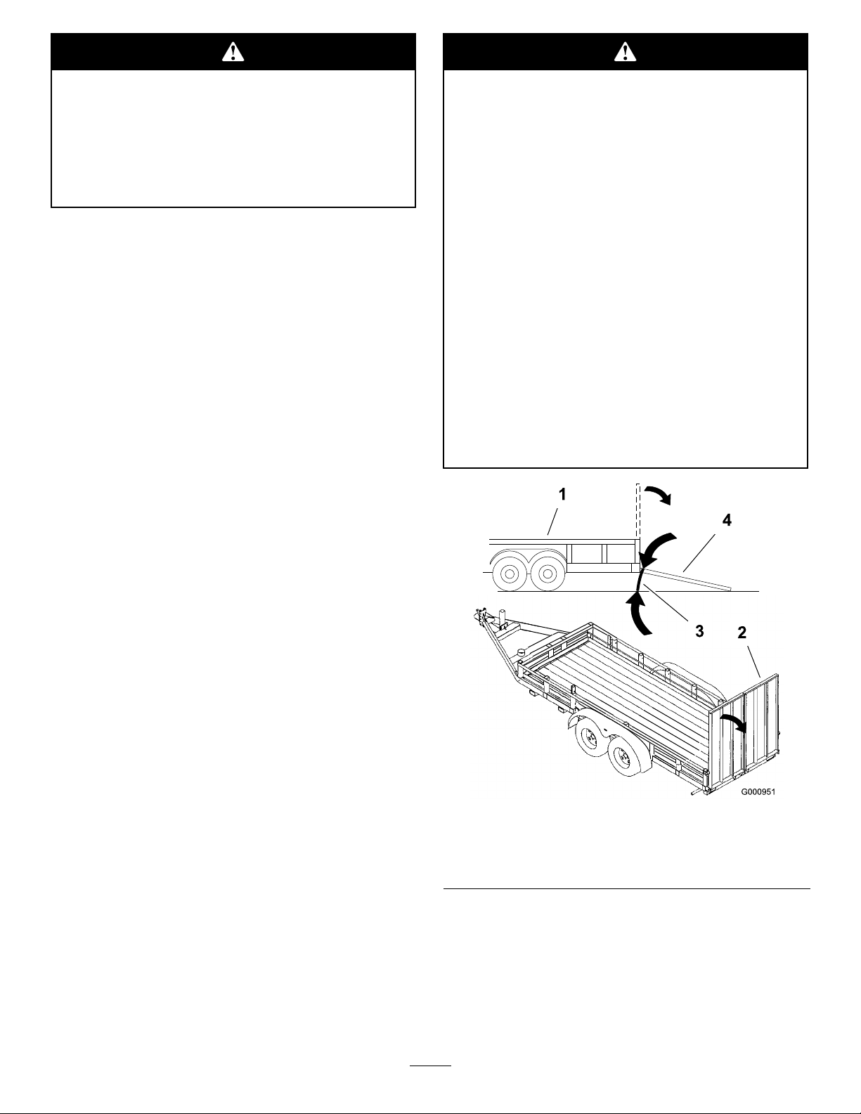
Useextremecautionwhenloadingunitsontrailersor
trucks.Onefullwidthrampthatiswideenoughto
extendbeyondthereartiresisrecommendedinsteadof
individualrampsforeachsideoftheunit(Figure23).
Thelowerrearsectionofthetractorframeextends
backbetweentherearwheelsandservesasastopfor
tippingbackward.Havingafullwidthrampprovides
asurfacefortheframememberstocontactifthe
unitstartstotipbackward.Ifitisnotpossibletouse
onefullwidthramp,useenoughindividualrampsto
simulateafullwidthcontinuousramp.
Loadingaunitontoatrailerortruckincreases
thepossibilityofbackwardtip-overandcould
causeseriousinjuryordeath.
•Useextremecautionwhenoperatingaunit
onaramp.
•Useonlyasingle,fullwidthramp;DoNot
useindividualrampsforeachsideofthe
unit.
•Ifindividualrampsmustbeused,use
enoughrampstocreateanunbrokenramp
surfacewiderthantheunit.
•Donotexceeda15degreeanglebetween
rampandgroundorbetweenrampand
trailerortruck.
•Avoidsuddenaccelerationwhiledrivingunit
uparamptoavoidtippingbackward.
•Avoidsuddendecelerationwhilebacking
unitdownaramptoavoidtippingbackward.
Therampshouldbelongenoughsothattheangles
donotexceed15degrees(Figure23).Asteeperangle
maycausemowercomponentstogetcaughtastheunit
movesfromramptotrailerortruck.Steeperangles
mayalsocausetheunittotipbackward.Ifloadingon
ornearaslope,positionthetrailerortrucksoitison
thedownsideoftheslopeandtherampextendsupthe
slope.Thiswillminimizetherampangle.Thetraileror
truckshouldbeaslevelaspossible.
Important:DoNotattempttoturntheunitwhile
ontheramp;youmaylosecontrolanddriveoff
theside.
Avoidsuddenaccelerationwhendrivinguparampand
suddendecelerationwhenbackingdownaramp.Both
maneuverscancausetheunittotipbackward.
Figure23
1.Trailer3.Notgreaterthan
15degrees
2.Fullwidthramp4.Fullwidthramp—sideview
OperatingTips
FastThrottleSetting
Forbestmowingandmaximumaircirculation,operate
theengineatthefastthrottleposition.Airisrequired
23
Page 24

tothoroughlycutgrassclippings,sodonotsetthe
height-of-cutsolowastototallysurroundthemower
byuncutgrass.Alwaystrytohaveonesideofthe
mowerfreefromuncutgrass,whichallowsairtobe
drawnintothemower.
CuttingaLawnfortheFirstTime
Cutgrassslightlylongerthannormaltoensurethe
cuttingheightofthemowerdoesnotscalpanyuneven
ground.However,thecuttingheightusedinthepastis
generallythebestonetouse.Whencuttinggrasslonger
thansixinchestall,youmaywanttocutthelawntwice
toensureanacceptablequalityofcut.
Cut1/3oftheGrassBlade
Itisbesttocutonlyabout1/3ofthegrassblade.
Cuttingmorethanthatisnotrecommendedunless
grassissparse,oritislatefallwhengrassgrowsmore
slowly.
MowingDirection
Alternatemowingdirectiontokeepthegrassstanding
straight.Thisalsohelpsdisperseclippingswhich
enhancesdecompositionandfertilization.
MowatCorrectIntervals
thissetting.Thencutthegrassagainusingthelower,
normalsetting.
WhenStopping
Ifthemachine’sforwardmotionmustbestoppedwhile
mowing,aclumpofgrassclippingsmaydropontoyour
lawn.T oavoidthis,moveontoapreviouslycutarea
withthebladesengaged.
KeeptheUndersideoftheMower
Clean
Cleanclippingsanddirtfromtheundersideofthe
moweraftereachuse.Ifgrassanddirtbuildupinside
themower,cuttingqualitywilleventuallybecome
unsatisfactory.
BladeMaintenance
Maintainasharpbladethroughoutthecuttingseason
becauseasharpbladecutscleanlywithouttearingor
shreddingthegrassblades.Tearingandshreddingturns
grassbrownattheedges,whichslowsgrowthand
increasesthechanceofdisease.Checkthecutterblades
dailyforsharpness,andforanywearordamage.File
downanynicksandsharpenthebladesasnecessary.If
abladeisdamagedorworn,replaceitimmediatelywith
agenuineTOROreplacementblade.
Normally,moweveryfourdays.Butremember,
grassgrowsatdifferentratesatdifferenttimes.So
tomaintainthesamecuttingheight,whichisagood
practice,mowmoreofteninearlyspring.Asthegrass
growthrateslowsinmidsummer,mowlessfrequently.
Ifyoucannotmowforanextendedperiod,rstmow
atahighcuttingheight;thenmowagaintwodayslater
atalowerheightsetting.
CuttingSpeed
Toimprovecutquality,useaslowergroundspeedin
certainconditions.
AvoidCuttingTooLow
Ifthecuttingwidthofthemoweriswiderthanthe
moweryoupreviouslyused,raisethecuttingheightto
ensurethatuneventurfisnotcuttooshort.
LongGrass
Ifthegrassiseverallowedtogrowslightlylongerthan
normal,orifitcontainsahighdegreeofmoisture,raise
thecuttingheighthigherthanusualandcutthegrassat
24
Page 25
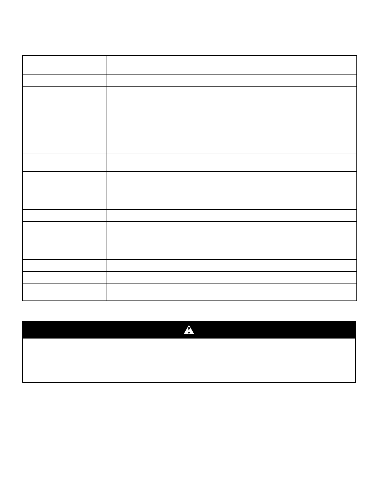
Maintenance
RecommendedMaintenanceSchedule(s)
MaintenanceService
Interval
Aftertherst8hours
Aftertherst25hours
Beforeeachuseordaily
Every25hours
Every50hours
Every100hours
Every150hours
Every200hours
MaintenanceProcedure
•Checkthehydraulicuid.
•Changethehydrauliclter.
•Checkthesafetyinterlocksystem.
•Checktheengineoillevel.
•Cleantheenginescreenandtheoilcooler.
•Checkthemowerblades.
•Cleanthemowerdeck.
•Greasethemowerbearings.
•Checkthehydraulicuid.
•Checkthetirepressure.ormonthly ,whicheveroccursrst.
•Checkthepumpdrivebelt.
•Changetheengineoil.
•Checkthewheelhubslottednut.
•Cleantheenginecylinderandcylinderheadcoolingns
•Inspectthebeltsforcracksandwear.
•Checkthehydraulichoses.
•Lubricatethemachinewithlightoil.
•Checkand/orreplacetheprimaryairlter.
•Replacetheoillter.
•Checkthesparkplugs.
•Replacethefuellteroryearly,whicheveroccursrst.
•Greasethebrakepivotandlever.
Every500hours
Every600hours
Yearly
•Adjustthecasterpivotbearingoratstorage,whichevercomesrst.
•Replacethesafetylter.
•Greasethefrontcasterpivots(moreoftenindirtyordustyconditions).
•Changethehydrauliclterandoil.
Important:Refertoyourengineoperator’smanualforadditionalmaintenanceprocedures.
Ifyouleavethekeyintheignitionswitch,someonecouldaccidentlystarttheengineandseriously
injureyouorotherbystanders.
Removethekeyfromtheignitionanddisconnectthewirefromthesparkplug(s)beforeyoudoany
maintenance.Setthewireasidesothatitdoesnotaccidentallycontactthesparkplug.
Lubrication
GreasingandLubrication
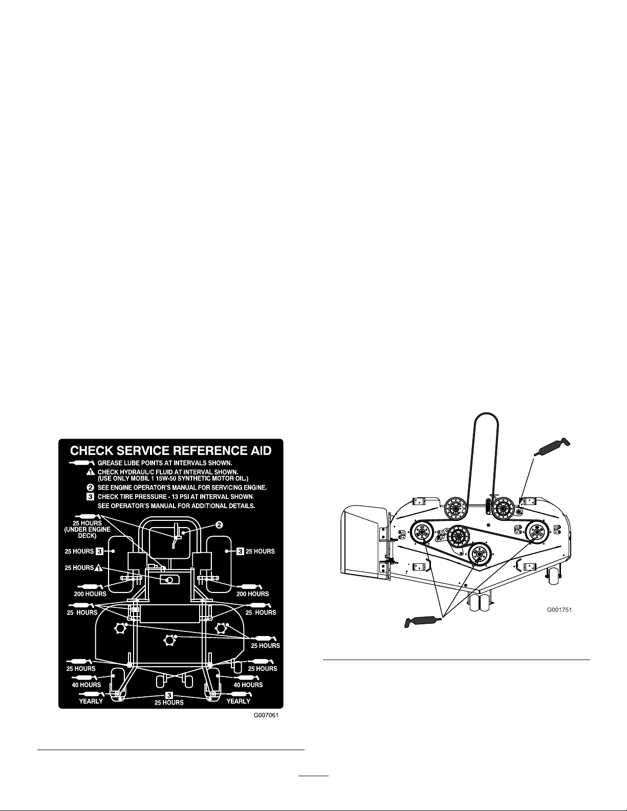
LubricatethemachinewhenshownontheCheckService
ReferenceAiddecal(Figure24).Greasemorefrequently
whenoperatingconditionsareextremelydustyorsandy .
GreaseType:General-purposegrease.
HowtoGrease
1.DisengagethePTO,movethemotioncontrollevers
totheneutrallockedpositionandsettheparking
brake.
25
Page 26
2.Stoptheengine,removethekey,andwaitforall
movingpartstostopbeforeleavingtheoperating
position.
3.Cleanthegreasettingswitharag.Makesureto
scrapeanypaintoffthefrontofthetting(s).
4.Connectagreaseguntothetting.Pumpgrease
intothettingsuntilgreasebeginstooozeoutof
thebearings.
5.Wipeupanyexcessgrease.
WheretoAddLightOilorSpray
Lubrication
ServiceInterval:Every150hours
Lubricatethemachineinthefollowingareaswithspray
typelubricantorlightoil.
•Seatswitchactuator.
•Brakehandlepivot.
•Brakerodbushings.
GreasingtheFrontCasterPivots
ServiceInterval:Yearly
1.Removethedustcapandadjustthecasterpivots.
Keepthedustcapoffuntilgreasingisdone.Referto
AdjustingtheCasterPivotBearinginDriveSystem
Maintenance,page33.
2.Removethehexplug.Threadagreasezerkintothe
hole.
3.Pumpgreaseintothezerkuntilitoozesoutaround
thetopbearing.
4.Removethegreasezerkinthehole.Installthehex
plugandcap.
WheretoAddGrease
LubricatethegreasettingsasshownontheCheck
ServiceReferenceAiddecal(Figure24).
•Motioncontrolbronzebushings.
GreasingtheBearings
ServiceInterval:Every25hours
GreasewithNo.2general-purposelithium-baseor
molybdenum-basegrease.
1.DisengagethePTO,movethemotioncontrollevers
totheneutrallockedposition,andsettheparking
brake.
2.Stoptheengine,removethekey,andwaitforall
movingpartstostopbeforeleavingtheoperating
position.
3.Greasethettingsonthe3spindlebearings
(Figure25).
Figure24
Figure25
4.Greasetheidlerpulleypivot(Figure25).
26
Page 27
EngineMaintenance
ServicingthePrimaryFilter
ServiceInterval:Every200hours
ServicingtheAirCleaner
Note:Checktheltersmorefrequentlyiftheoperating
conditionsareextremelydustyorsandy .
RemovingtheFilters
1.DisengagethePTO,movethemotioncontrollevers
totheneutrallockedposition,andsettheparking
brake.
2.Stoptheengine,removethekey,andwaitforall
movingpartstostopbeforeleavingtheoperating
position.
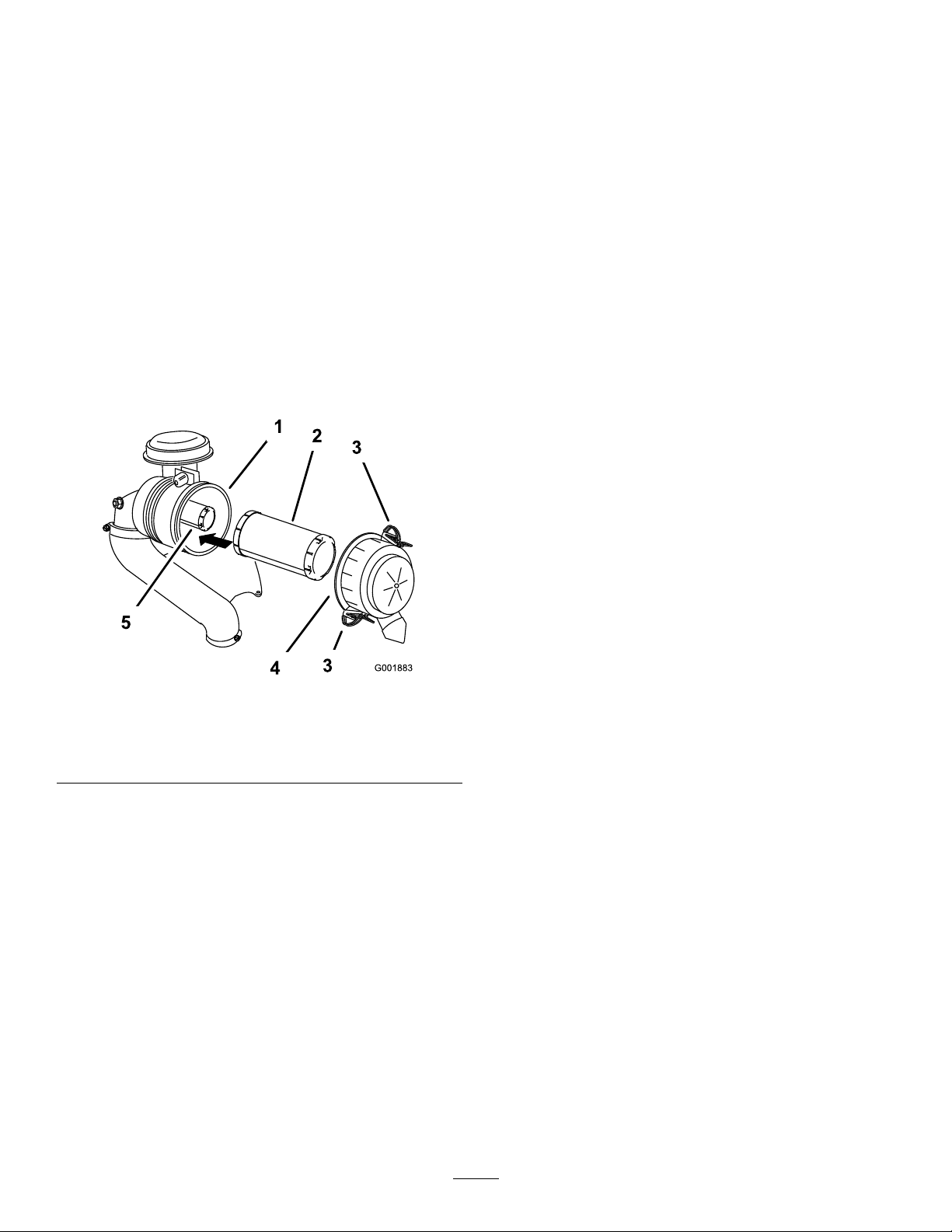
3.Releasethelatchesontheaircleanerandpulltheair
cleanercoverofftheaircleanerbody(Figure26).
•Iftheprimarylterisdirty,bent,ordamaged,
replaceit.
•Donotcleantheprimarylter.
ServicingtheSafetyFilter
ServiceInterval:Every600hours
Important:Neverattempttocleanthesafetylter.
Ifthesafetylterisdirty,thentheprimarylteris
damaged.Replacebothlters.
InstallingtheFilters
Important:Topreventenginedamage,always
operatetheenginewithbothairltersandcover
installed.
1.Ifinstallingnewlters,checkeachlterforshipping
damage.Donotuseadamagedlter.
2.Ifthesafetylterisbeingreplaced,carefullyslideit
intothelterbody(Figure26).
Figure26
1.Aircleanerbody4.Aircleanercover
2.Primarylter5.Safetylter
3.Latch
4.Cleantheinsideoftheaircleanercoverwith
compressedair.
5.Gentlyslidetheprimarylteroutoftheaircleaner
body(Figure26).
Note:Avoidknockingthelterintothesideofthe
body.
6.Removethesafetylteronlyifyouintendtoreplace
it.
Important:Neverattempttocleanthesafety
lter.Ifthesafetylterisdirty,thentheprimary
lterisdamaged.Replacebothlters.
3.Carefullyslidetheprimarylteroverthesafetylter
(Figure26).
Note:Ensurethattheprimarylterisfullyseated
bypushingonitsouterrimwhileinstallingit.
Important:Donotpressonthesoftinsidearea
ofthelter.
4.Installtheaircleanercoverwiththesideindicatedas
upfacingupwardandsecurethelatches(Figure26).
ServicingtheEngineOil
Note:Changetheoilmorefrequentlywhenthe
operatingconditionsareextremelydustyorsandy .
OilType:Detergentoil(APIserviceSG,SH,SJor
higher)
CrankcaseCapacity:w/lter,67oz.(2l)
Viscosity:Seethetablebelow .
7.Inspecttheprimarylterfordamagebylookinginto
thelterwhileshiningabrightlightontheoutside
ofthelter.Holesinthelterwillappearasbright
spots.Ifthelterisdamaged,discardit.
27
Page 28
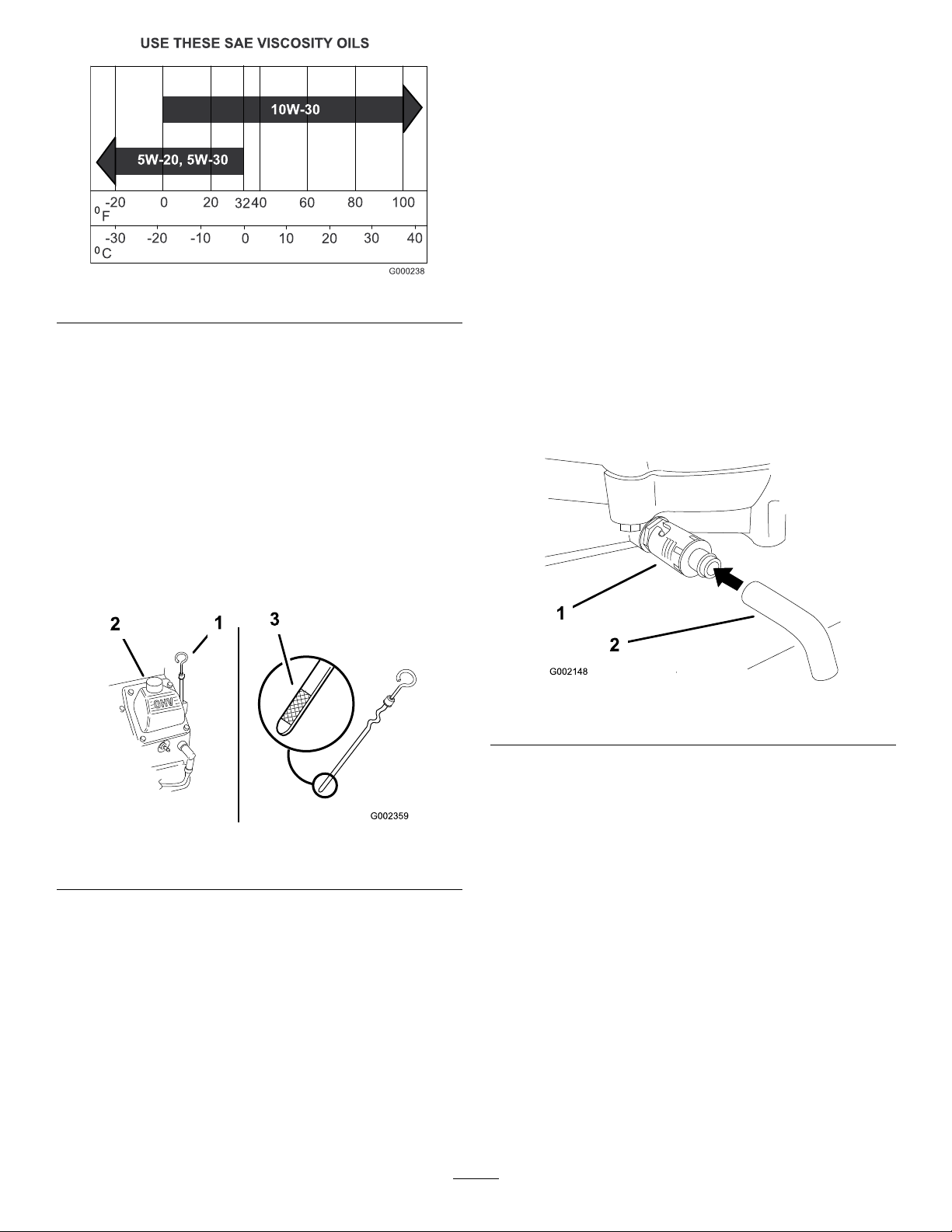
Figure27
CheckingtheEngineOilLevel
ServiceInterval:Beforeeachuseordaily
1.Parkthemachineonalevelsurface.
2.DisengagethePTO,turntheignitionkeytooff,and
removethekey.
ChangingtheOil
ServiceInterval:Every100hours
1.Starttheengineandletitrunveminutes.This
warmstheoilsoitdrainsbetter.
2.Parkthemachinesothatthedrainsideisslightly
lowerthantheoppositesidetoensuretheoildrains
completely.
3.DisengagethePTOandsettheparkingbrake.
4.Stoptheengine,removethekey,andwaitforall
movingpartstostopbeforeleavingtheoperating
position.
5.Placeapanbelowthedrain.Rotateoildrainvalveto
allowoiltodrain(Figure29).
6.Whenoilhasdrainedcompletely,closethedrain
valve.
Note:Disposeoftheusedoilatarecyclingcenter.
3.Waitforallmovingpartstostopbeforeleavingthe
operatingpositionandthenchockorblocktires.
4.Cleanaroundtheoildipstick(Figure28)sothatdirt
cannotfallintothellerholeanddamagetheengine.
Figure28
1.Oildipstick
2.Fillertube
5.Unscrewtheoildipstickandwipetheendclean
(Figure28).
6.Slidetheoildipstickfullyintothellertube,butdo
notthreadontotube(Figure28).
7.Pullthedipstickoutandlookatthemetalend.Ifthe
oillevelislow,slowlypouronlyenoughoilintothe
llertubetoraisetheleveltotheFullmark.
Important:Donotoverllthecrankcasewith
oilandruntheengine;enginedamagecan
result.
Figure29
1.Oildrainvalve2.Oildrainhose
7.Slowlypourapproximately80%ofthespeciedoil
intothellertube(Figure28).
8.Checktheoillevel;refertoCheckingtheEngineOil
Level.
9.SlowlyaddtheadditionaloiltobringittotheFull
mark.
ChangingtheOilFilter
ServiceInterval:Every200hours
Note:Changetheoilltermorefrequentlywhenthe
operatingconditionsareextremelydustyorsandy .
1.Draintheoilfromtheengine;refertoChangingthe
EngineOil.
2.Removetheoldlterandwipethelleradapter
gasketsurface(Figure30).
28
Page 29
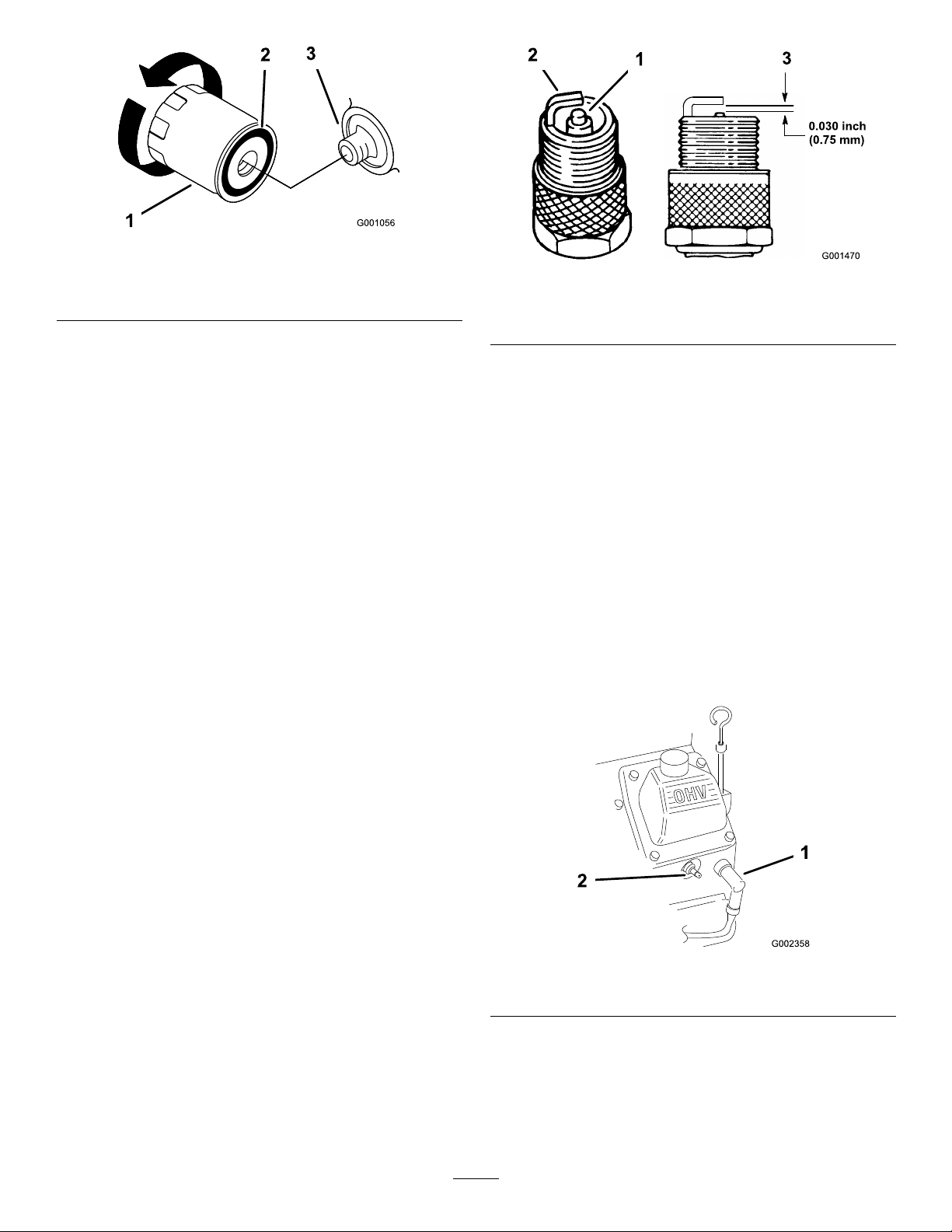
Figure30
1.Oillter
2.Adaptergasket
3.Adapter
3.Pournewoilinthroughthecenterholeofthelter.
Fillituptothebottomofthethreadsinside.
4.Allowtheltermaterialtoabsorbthenewoilfor
1to2minutes.
Figure31
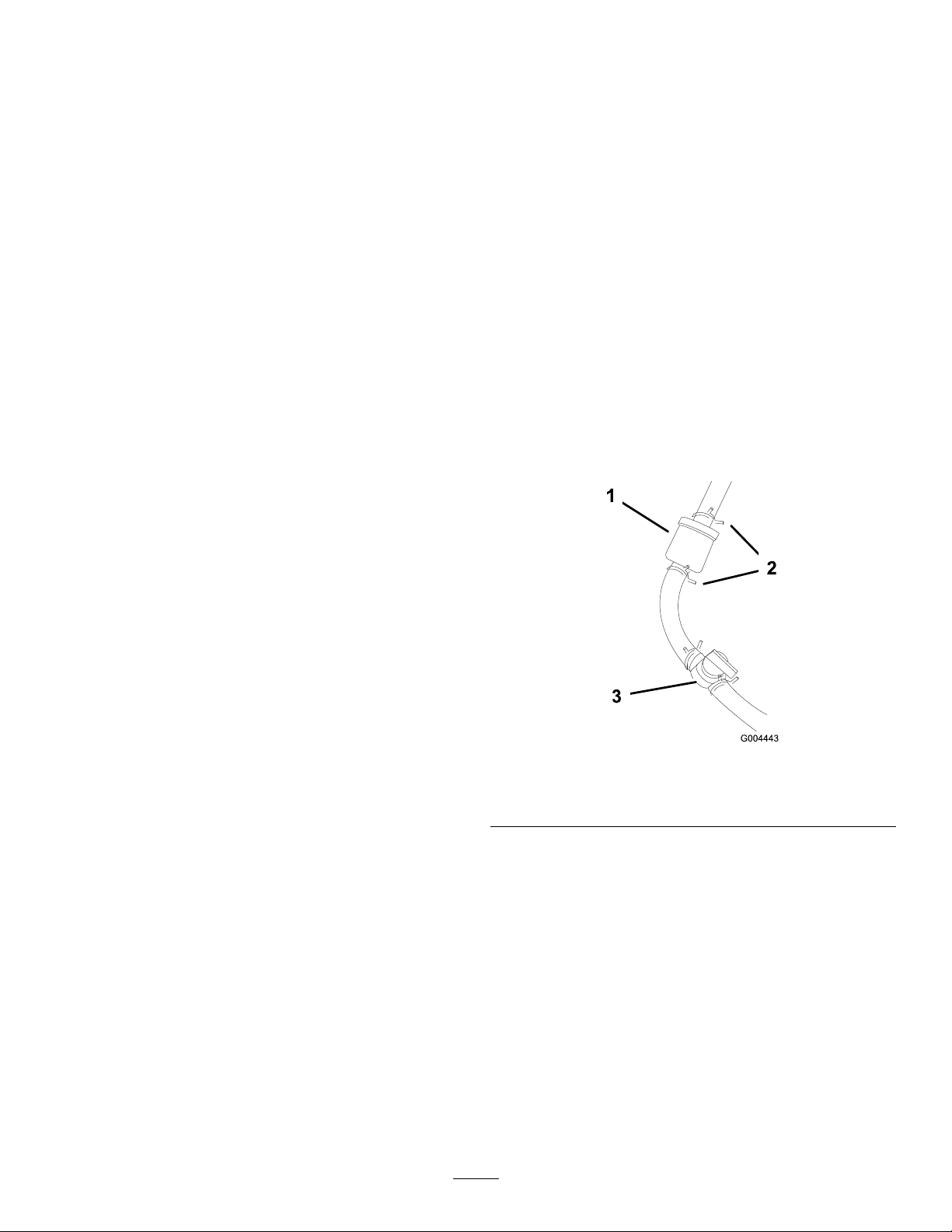
1.Centerelectrodeinsulator3.Airgap(nottoscale)
2.Sideelectrode
Important:Alwaysreplacethesparkplugs
whenithasablackcoating,wornelectrodes,
anoilylm,orcracks.
5.Applyathincoatofnewoiltotherubbergasketon
thereplacementlter(Figure30).
6.Installthereplacementoilltertothelteradapter,
turntheoillterclockwiseuntiltherubbergasket
contactsthelteradapter,thentightenthelteran
additional2/3to1turn(Figure30).
7.Fillthecrankcasewiththepropertypeofnewoil;
refertoServicingtheEngineOil.
8.Runtheengineforabout3minutes,stoptheengine,
andcheckforoilleaksaroundtheoillter.
9.Checktheengineoillevelandaddoilifneeded.
ServicingtheSparkPlugs
Ensurethattheairgapbetweenthecenterandside
electrodesiscorrectbeforeinstallingthesparkplug.
Useasparkplugwrenchforremovingandinstallingthe
sparkplugsandagappingtool/feelergaugetocheckand
adjusttheairgap.Installanewsparkplugsifnecessary.
Type:Champion®RC12YC,Champion®Platinum
3071orequivalent
2.Checkthegapbetweenthecenterandsideelectrodes
(Figure31).Bendthesideelectrode(Figure31)if
thegapisnotcorrect.
RemovingtheSparkPlugs
1.DisengagethePTOandsettheparkingbrake.
2.Stoptheengine,removethekey,andwaitforall
movingpartstostopbeforeleavingtheoperating
position.
3.Disconnectthewiresfromthesparkplugs
(Figure32).
AirGap:0.030inch(0.76mm)
CheckingtheSparkPlugs
ServiceInterval:Every200hours
1.Lookatthecenterofthesparkplugs(Figure31).
Ifyouseelightbrownorgrayontheinsulator,the
engineisoperatingproperly .Ablackcoatingonthe
insulatorusuallymeansthattheaircleanerisdirty.
Figure32
1.Spark-plugwire/sparkplug
4.Cleanaroundthesparkplugstopreventdirtfrom
fallingintotheengineandpotentiallycausing
damage.
5.Removethesparkplugsandthemetalwashers.
29
Page 30
InstallingtheSparkPlugs
1.Installthesparkplugsandthemetalwasher.Ensure
thattheairgapissetcorrectly.
2.Tightenthesparkplugsto18to22ft-lb(24.4to
29.8N⋅m).
FuelSystem
Maintenance
ReplacingtheFuelFilter
3.Connectthewirestothesparkplugs(Figure32).
ServiceInterval:Every200hoursoryearly ,whichever
occursrst.
Neverinstalladirtylterifitisremovedfromthefuel
line.
1.DisengagethePTO,movethemotioncontrollevers
totheneutrallockedpositionandsettheparking
brake.
2.Stoptheengine,removethekey,andwaitforall
movingpartstostopbeforeleavingtheoperating
position.
3.Allowtheenginetocooldown.
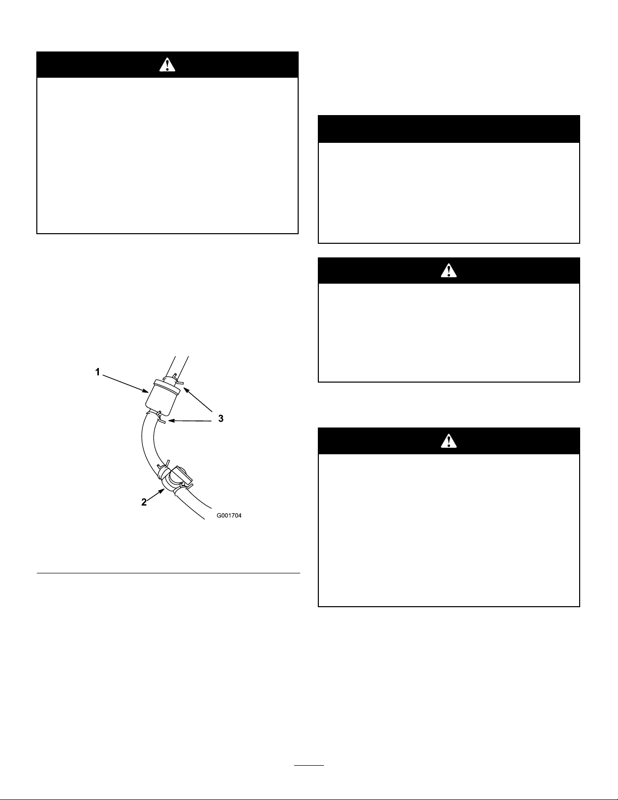
4.Closethefuelshut-offvalve(Figure33).
Figure33
1.Filter
2.Hoseclamp
5.Squeezetheendsofthehoseclampstogetherand
slidethemawayfromthelter(Figure33).
6.Removethelterfromthefuellines.
7.Installanewlterandmovethehoseclampsclose
totheltertosecurethefuelline(Figure33).
8.Wipeupanyspilledfuel.
9.Openthefuelshut-offvalve.
30
3.Fuelshut-offvalve
Page 31
DrainingtheFuelTank
ElectricalSystem
Maintenance
Incertainconditions,gasolineisextremely
ammableandhighlyexplosive.Areor
explosionfromgasolinecanburnyouand
othersandcandamageproperty.
•Draingasolinefromthefueltankwhenthe
engineiscold.Dothisoutdoorsinanopen
area.Wipeupanygasolinethatspills.
•Neversmokewhendraininggasoline,and
stayawayfromanopenameorwherea
sparkmayignitethegasolinefumes.
1.DisengagethePTO,movethemotioncontrollevers
totheneutrallockedpositionandsettheparking
brake.
2.Stoptheengine,removethekey,andwaitforall
movingpartstostopbeforeleavingtheoperating
position.
3.Closefuelshut-offvalve(Figure34).
ServicingtheBattery
Warning
CALIFORNIA
Proposition65Warning
Batteryposts,terminals,andrelated
accessoriescontainleadandleadcompounds,
chemicalsknowntotheStateofCalifornia
tocausecancerandreproductiveharm.
Washhandsafterhandling.
Batteryelectrolytecontainssulfuricacidwhich
isadeadlypoisonandcausessevereburns.
Donotdrinkelectrolyteandavoidcontactwith
skin,eyesorclothing.Wearsafetyglassesto
shieldyoureyesandrubberglovestoprotect
yourhands.
Figure34
1.Filter3.Hoseclamp
2.Fuelshut-offvalve
4.Loosenthehoseclampatthefuellterandslideit
awayfromthefuellter(Figure34).
5.Pullthefuellineofffuellter(Figure34).Openfuel
shut-offvalveandallowgasolinetodrainintoagas
canordrainpan.
Note:Nowisthebesttimetoinstallanewfuel
lterbecausethefueltankisempty .
6.Installthefuellineontothefuellter.Slidethehose
clampclosetothefuelltertosecurethefuelline
(Figure34).
RemovingtheBattery
Batteryterminalsormetaltoolscouldshort
againstmetalmachinecomponentscausing
sparks.Sparkscancausethebatterygassesto
explode,resultinginpersonalinjury.
•Whenremovingorinstallingthebattery,do
notallowthebatteryterminalstotouchany
metalpartsofthemachine.
•Donotallowmetaltoolstoshortbetween
thebatteryterminalsandmetalpartsofthe
machine.
31
Page 32
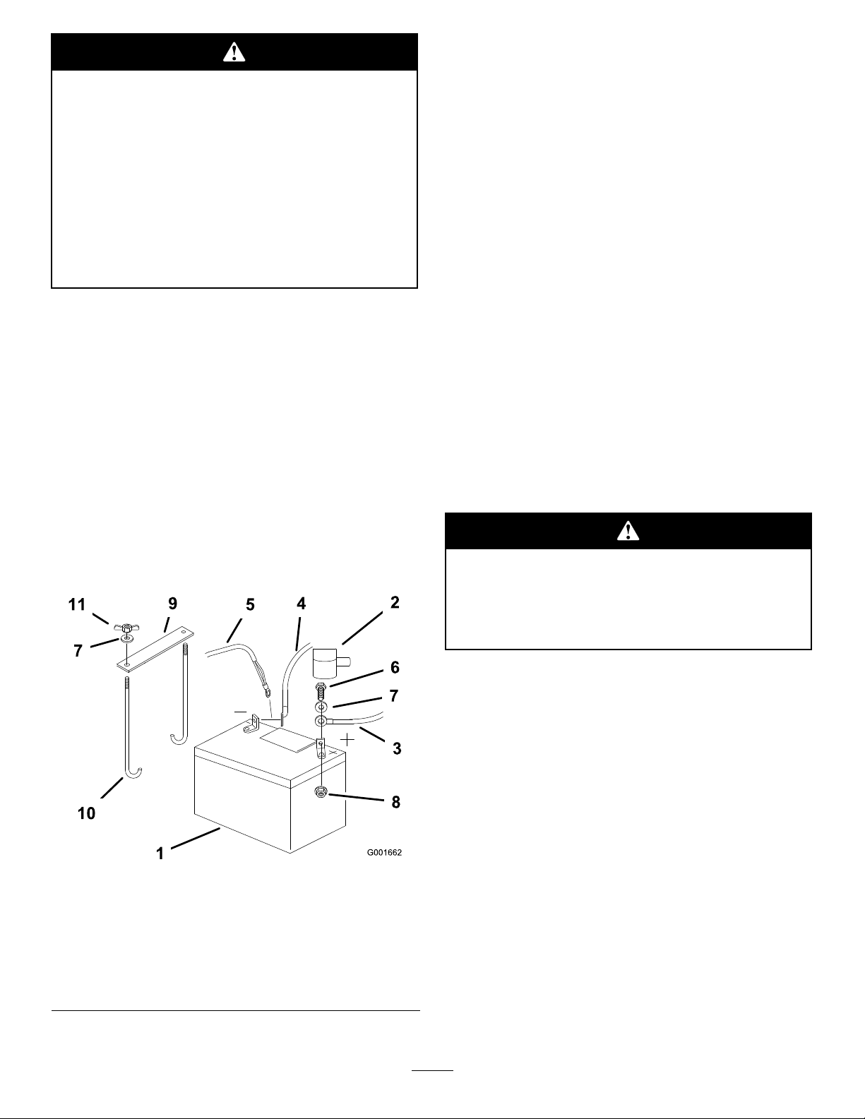
6.Removebothwingnuts(1/4inch)securingthe
batteryclamp(Figure35).
Incorrectbatterycableroutingcoulddamage
themachineandcablescausingsparks.Sparks
cancausethebatterygassestoexplode,
resultinginpersonalinjury.
•AlwaysDisconnectthenegative(black)
batterycablebeforedisconnectingthe
positive(red)cable.
•AlwaysReconnectthepositive(red)battery
cablebeforereconnectingthenegative
(black)cable.
1.DisengagethePTO,movethemotioncontrollevers
totheneutrallockedposition,andsettheparking
brake.
2.Stoptheengine,removethekey,andwaitforall
movingpartstostopbeforeleavingtheoperating
position.
3.Unlatchtheseatandtilttheseatup.
4.Firstdisconnectthenegativebatterycableand
groundwirefromthenegative(-)batteryterminal
(Figure35).
7.Removethebattery.
InstallingtheBattery
1.Positionbatteryinthetraywiththeterminalposts
towardtheengine(Figure35).
2.First,installthepositive(red)batterycableto
positive(+)batteryterminal.
3.Theninstallthenegativebatterycableandground
wiretothenegative(-)batteryterminal.
4.Securethecableswith2bolts(1/4x3/4inch),
2washers(1/4inch),and2locknuts(1/4inch)
(Figure35).
5.Slidetheredterminalbootontothepositive(red)
batterypost.
6.SecurebatterywithJ-bolts,holddownclampand
2washers(1/4inch),and2wingnuts(1/4inch)
(Figure35).
ChargingtheBattery
5.Slidetheredterminalbootoffthepositive(red)
batteryterminal.Thenremovethepositive(red)
batterycable(Figure35).
Figure35
1.Battery
2.Terminalboot
3.Positivebatterycable9.Batteryclamp
4.Negativebatterycable10.J-bolts
5.Groundwire11.Wingnut(1/4inch)
6.Bolt(1/4x3/4inch)
7.Washer(1/4inch)
8.Locknut(1/4inch)
Chargingthebatteryproducesgassesthatcan
explode.
Neversmokenearthebatteryandkeepsparks
andamesawayfrombattery.
Important:Alwayskeepthebatteryfullycharged
(1.265specicgravity).Thisisespeciallyimportant
topreventbatterydamagewhenthetemperatureis
below32°F(0°C).
1.Removethebatteryfromthechassis.
2.Chargebatteryfor10to15minutesat25to30amps
or30minutesat4-6amps.
3.Whenthebatteryisfullycharged,unplugthecharger
fromtheelectricaloutlet,thendisconnectthe
chargerleadsfromthebatteryposts(Figure36).
32
Page 33
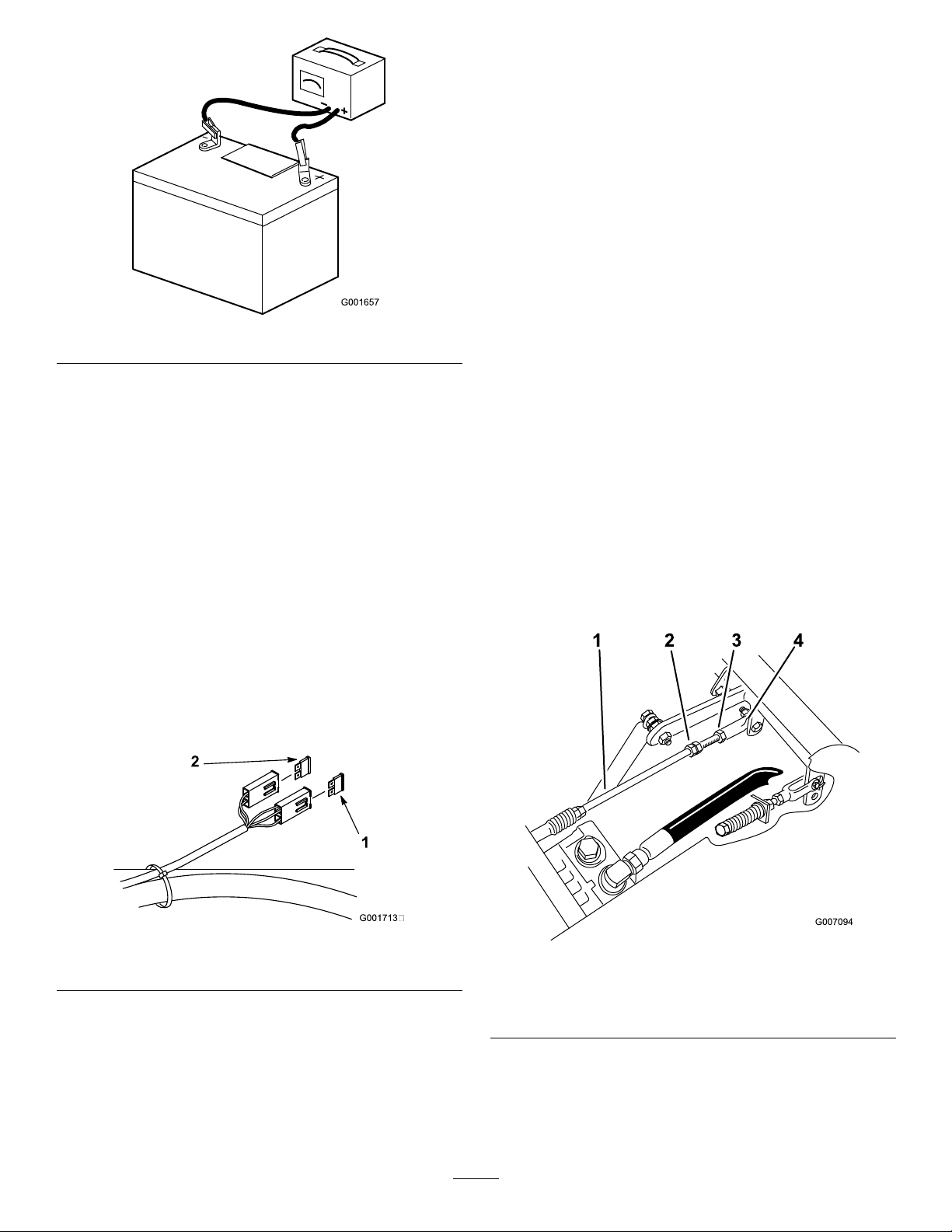
Figure36
4.Installthebatteryinthemachineandconnectthe
batterycables;refertoInstallingtheBattery.
Note:Donotrunthemachinewiththebattery
disconnected,electricaldamagemayoccur.
ServicingtheFuses
Theelectricalsystemisprotectedbyfuses.Itrequires
nomaintenance,however,ifafuseblowscheck
component/circuitformalfunctionorshort.
Thefusesareasfollows:
DriveSystem
Maintenance
AdjustingtheTracking
Note:Determinetheleftandrightsidesofthemachine
fromthenormaloperatingposition.
Note:Adjustthehandleneutralandhydraulicpump
neutralbeforeadjustingthetracking.RefertoAdjusting
theHandleNeutralandAdjustingtheHydraulicPump
Neutral.
1.Pushbothcontrolleversforwardthesamedistance.
2.Checkifthemachinepullstooneside.Ifitdoes,
stopthemachineandsettheparkingbrake.
3.Unlatchtheseatandtiptheseatuptoaccessthe
pumpcontrolrod.
4.Loosenthelocknutattheballjointonrighthand
pumpcontrolrod(Figure38).
•Tomakethemachinegoright,rotatethedouble
nutsonrodtotherightsideofthemachine.
•Tomakethemachinegoleft,rotatethedouble
nutsonrodtotheleftsideofthemachine.
5.Tightenthelocknutattheballjointandtestthe
tracking(Figure38).
6.Repeatthisadjustmentuntilthetrackingiscorrect.
•MainF1-30amp,blade-type
•AlternatorF2-25amp,blade-type
1.Unlatchtheseatandraisetheseattogainaccessto
fuseholder(Figure37).
Figure37
1.MainF1-30amp2.AlternatorF2-25amp
2.Toreplacethefuses,pulloutonthefusetoremove
it.
3.Installanewfuse(Figure37).
Figure38
1.Righthandpumpcontrol
rod
2.Doublenuts4.Balljoint
CheckingtheTirePressure
3.Locknut
ServiceInterval:Every50hoursormonthly ,whichever
occursrst.
33
Page 34
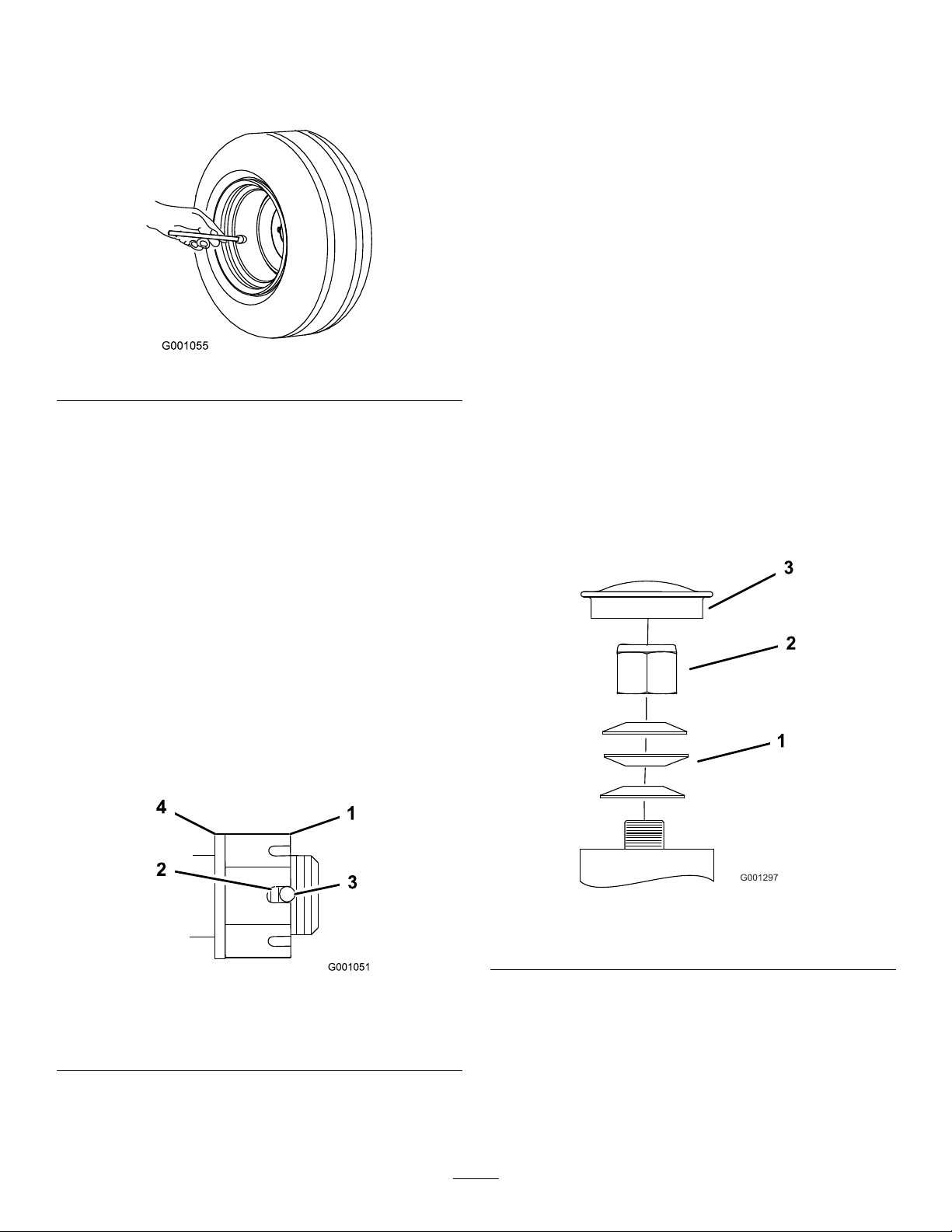
Maintaintheairpressureinthefrontandreartiresat
13psi(90kPa).Uneventirepressurecancauseuneven
cut.Checkthetireswhentheyarecoldtogetthemost
accuratepressurereading(Figure39).
6.Ifmorethantwothreadsareshowingremovenut
andinstallwasherbetweenhubandnut.
7.Torquetheslottednutto125ft-lb.(170N⋅m)
(Figure40).
8.Tightenthenutuntilthenextsetofslotslineupwith
theholeintheshaft(Figure40).
9.Replacethecotterpin.
AdjustingtheCasterPivot
Bearing
ServiceInterval:Every500hoursoratstorage,which
evercomesrst.
Figure39
CheckingtheWheelHub
SlottedNut
ServiceInterval:Every100hours
Theslottednutneedstobetorquedto125ft-lb
(170N⋅m).
1.DisengagethePTO,movethemotioncontrollevers
totheneutrallockedpositionandsettheparking
brake.
2.Stoptheengine,removethekey,andwaitforall
movingpartstostopbeforeleavingtheoperating
position.
3.Removethecotterpin.
4.Torquetheslottednutto125ft-lb(170N⋅m)
(Figure40).
1.DisengagethePTO,movethemotioncontrollevers
totheneutrallockedpositionandsettheparking
brake.
2.Stoptheengine,removethekey,andwaitforall
movingpartstostopbeforeleavingtheoperating
position.
3.Removethedustcapfromcasterandtightenlock
nut(Figure41).
Figure40
1.SlottedNut3.Holeinthreadedshaft
2.Twothreadsorless
showing
4.Washer(ifneeded)
5.Checkthedistancefrombottomofslotinnutto
insideedgeofhole.Twothreadsorlessshouldbe
showing(Figure40).
Figure41
1.SpringWashers3.DustCap
2.LockNut
4.Tightenthelocknutuntilthespringwashersareat
andthenbackoffa1/4turntoproperlysetthe
pre-loadonthebearings(Figure41).
Important:Makesurespringwashersare
installedcorrectlyasshowninFigure41.
5.Installthedustcap(Figure41).
34
Page 35
CoolingSystem
Maintenance
BrakeMaintenance
AdjustingtheParkingBrake
CleaningtheEngineScreen
andtheOilCooler
ServiceInterval:Beforeeachuseordaily
Beforeeachuse,checkandcleantheenginescreenand
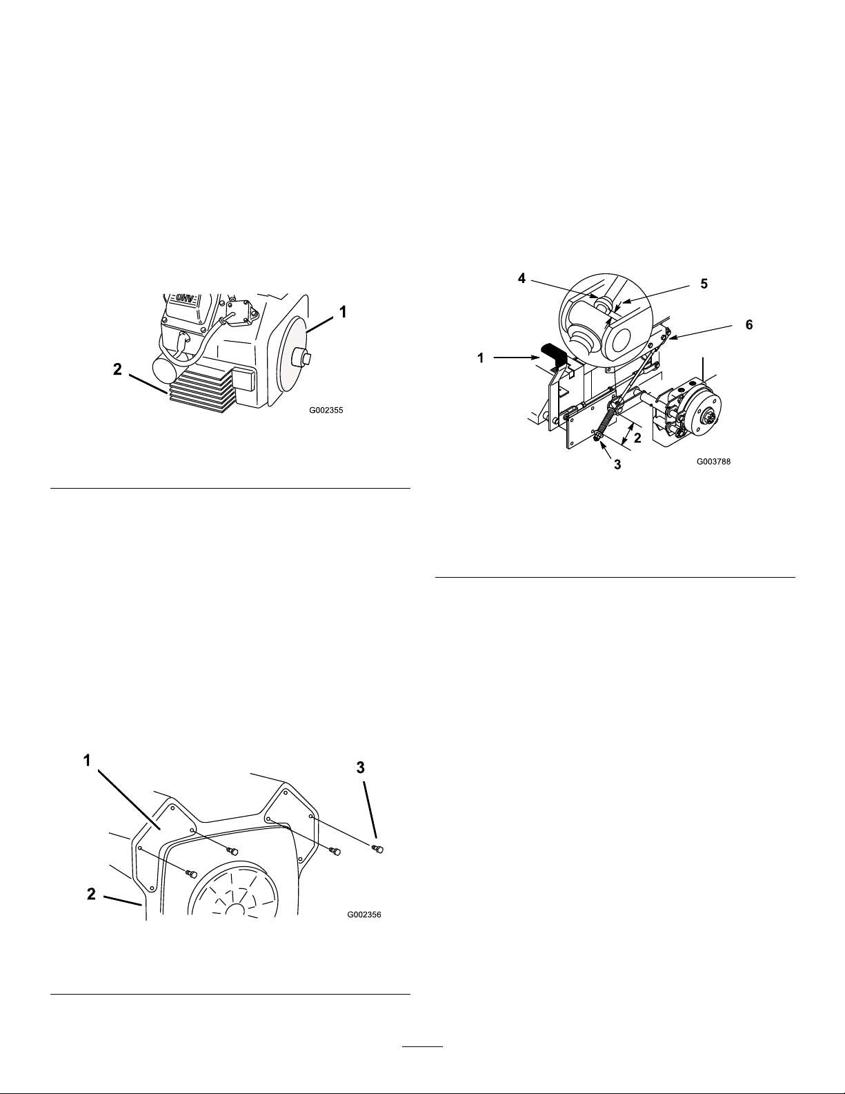
oilcooler.Removeanybuild-upofgrass,dirtorother
debrisfromtheoilcoolerscreenandenginescreen
(Figure42andFigure43).
Figure42
1.Enginescreen
2.Oilcooler
CleaningtheEngineFins
ServiceInterval:Every100hours
ServiceInterval:Every200hours
Checktheparkingbrakeforproperadjustment.
1.Disengagebrakelever(leverdown).
2.Measurethelengthofthespring.
Themeasurementshouldbe2-3/4inch(70mm)
betweenwashers(Figure44).
Figure44
1.Brakelever
2.Spring(2-3/4inches/70
mm)
3.Adjustingnuts6.Jamnutandyoke
4.Collaronbrakerod
5.3/16–1/4inch(5–7mm)
Cleanaroundthecarburetor,thegovernorleversand
thelinkage.Thiswillmakesureadequatecoolingto
hydraulicpumps,motorsandengineandwillreducethe
possibilityofoverheatingandmechanicaldamage.
1.Removetheengineshroud.
2.Cleantheenginecoolingns.
3.Installtheengineshroud.
Figure43
1.Panel
2.Engineshroud
3.Screws
3.Ifadjustmentisnecessary,loosenthejamnutbelow
thespringandtightenthenutdirectlybelowthe
yoke(Figure44).Turnthenutuntilthecorrect
measurementisobtained.Tightenthetwonuts
togetherandrepeatonoppositesideofunit.
4.Turnnutsclockwisetoshortenspringlengthand
turncounter-clockwisetolengthenthespring.
5.Engageparkingbrake,leverup.
6.Measurethedistancebetweenthetrunnionroller
andthecollaronbrakerod.
Themeasurementshouldbe3/16-1/4inch(5-7
mm)(Figure44).
7.Ifadjustmentisnecessary,loosenthejamnut
directlybelowtheyoke.Turnthebottomroduntil
thecorrectmeasurementisobtained(Figure44).
Tightenjamnutatyoke
35
Page 36
BeltMaintenance
InspectingtheBelts
ServiceInterval:Every100hours
Checkthebeltsforcracks,frayededges,burnmarksor
anyotherdamage.Replacedamagedbelts.
ReplacingtheMowerBelt
Squealingwhenthebeltisrotating,bladesslippingwhen
cuttinggrass,frayedbeltedges,burnmarksandcracks
aresignsofawornmowerbelt.Replacethemowerbelt
ifanyoftheseconditionsareevident.
1.DisengagethePTO,movethemotioncontrollevers
totheneutrallockedposition,andsettheparking
brake.
2.Stoptheengine,removethekey,andwaitforall
movingpartstostopbeforeleavingtheoperating
position.
3.Removethebeltcovers.
4.Loosenthenutsecuringtheidlerplateandmove
theidlerplatetorelievethebelttensionontheidler
pulley(Figure45).
5.Removethenut,washerandbeltguidefromtherear
leftsidepulley .
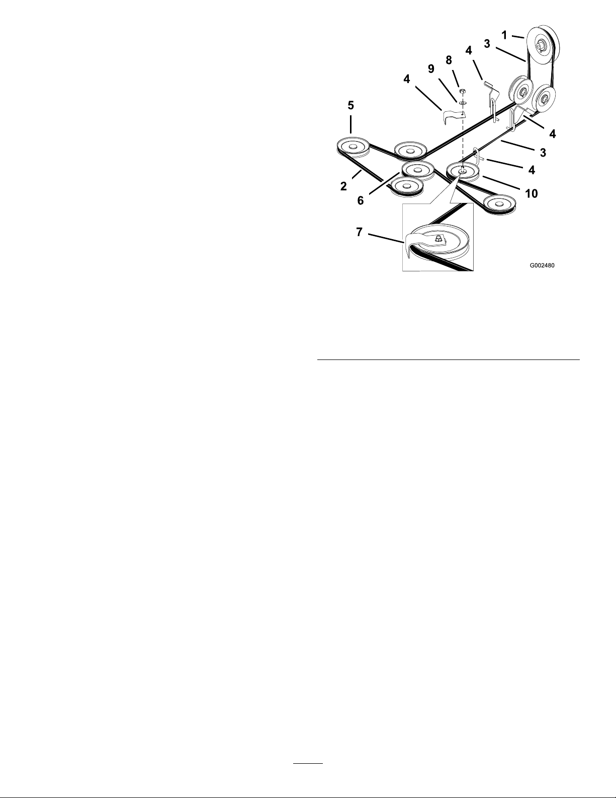
Figure45
1.Clutch
2.Mowerbelt7.Beltguideinstalled
3.1/4trunbelttwist
4.Beltguide9.Washer
5.Mowerspindlepulley
9.Adjustthebelttension,refertoAdjustingtheMower
BeltTension.
10.Installthebeltcoversandclosethelatches.
6.Moweridlerpulley
8.Nut
10.Rearleftsidepulley
6.Removethemowerbeltfromthebeltguidesand
removethebelt(Figure45).
7.Installthenewmowerbeltaroundthemowerspindle
pulleys,moweridlerpulley,intothebeltguides,into
rearidlerarmassembly,andtheclutch(Figure45).
8.Installthebeltguidewithawasherandnutontothe
rearleftsidepulley .
Note:Checktheamountoftwistinthebelt
betweenthepulleys.Ensureitisonlywhatis
speciedinFigure45.
AdjustingtheMowerBelt
Tension
1.DisengagethePTO,movethemotioncontrollevers
totheneutrallockedposition,andsettheparking
brake.
2.Stoptheengine,removethekey,andwaitforall
movingpartstostopbeforeleavingtheoperating
position.
3.Raisethemowertothetransportposition.
Important:Checktheamountoftwistinthe
beltbetweenthepulleys.Makesureitisonly
whatisspeciedinFigure45.
Important:Checkandmakesurethebeltis
installedintoboththefrontandrearbeltguides
(Figure46).
4.Checkthebelttension.Thespringloadedidler
centerboltneedstobenearthetopalignmenthole
inleftsupportplate(Figure46).
36
Page 37
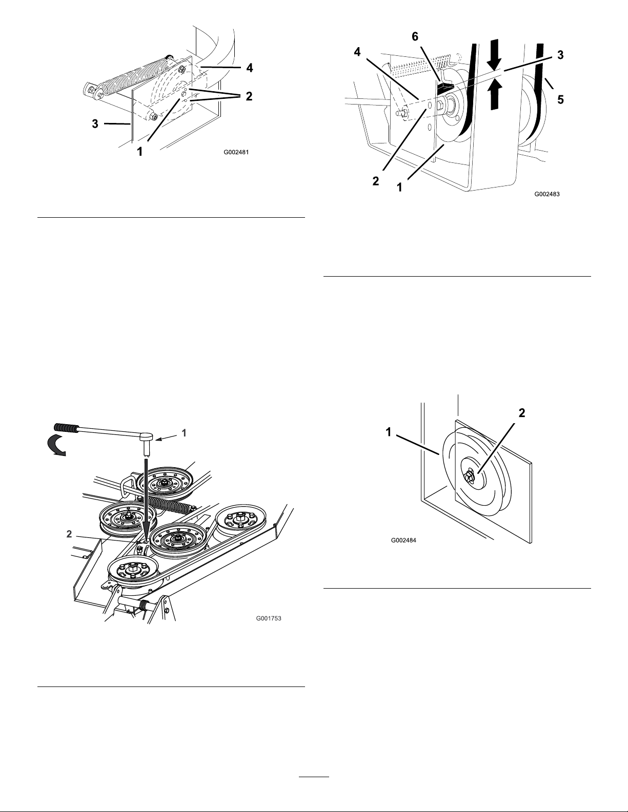
Figure46
1.Centerbolt3.Leftsupportplate
2.Alignmenthole
4.Springloadedidler
5.Ifadjustmentisrequired,loosentheidlerplateto
adjustit(Figure47).
6.Insertaratchetorbreakerbarintothesquareholein
theidlerplatetoadjustthetension(Figure47).
7.Toincreasebelttension,rotatetheratchetorbreaker
bartomovethexedidleruntilyoufeelincreased
resistanceandthespring-loadedidlerpulleystops
moving(Figure47).
Note:Donotincreasethebelttensionbeyondthe
pointwherethexedidlerarmstops.
8.Whileholdingthebelttension,tightentheidlerplate
boltsthatsecuretheidlerplate(Figure47).
Figure48
1.Springloadedidlerpulley
2.Topalignmenthole5.Belt
3.0to1/4inchgap(0to6
mm)
4.Idlerpulleyarm
6.Rubberbumper
10.Adjustthebelttensionandtheidlerplate,if
necessary,andtightenallhardwaresecurely
(Figure47).
11.Iftheidlerplatecontactstheendoftheadjustment
slotandmorebelttensionisrequired,asmallchange
totherightsidexedidlercancreatemorebelt
tensionadjustment(Figure49).
Figure47
1.Rachetwithshort
extensionorbreaker
bar
2.IdlerplatewithSquare
hole
9.Checkthedistancefromtherubberstopandthe
armofthespringloadedidlerpulleywhentheidler
plateistightened.Itneedstobe0to1/4inch(0to
6mm)fromtherubberstop(Figure48).
Figure49
1.Fixedidler2.Adjustmentslot
CheckingandReplacingthe
PumpDriveBelt
ServiceInterval:Every50hours—Checkthepump
drivebelt.
1.Checkthepumpdrivebeltforwear.
2.Pullthespringloadedidlerdownandremove
tractionbeltfromtheengineandhydropump
pulleys(Figure50).Removebeltbetweenpulleys.
37
Page 38
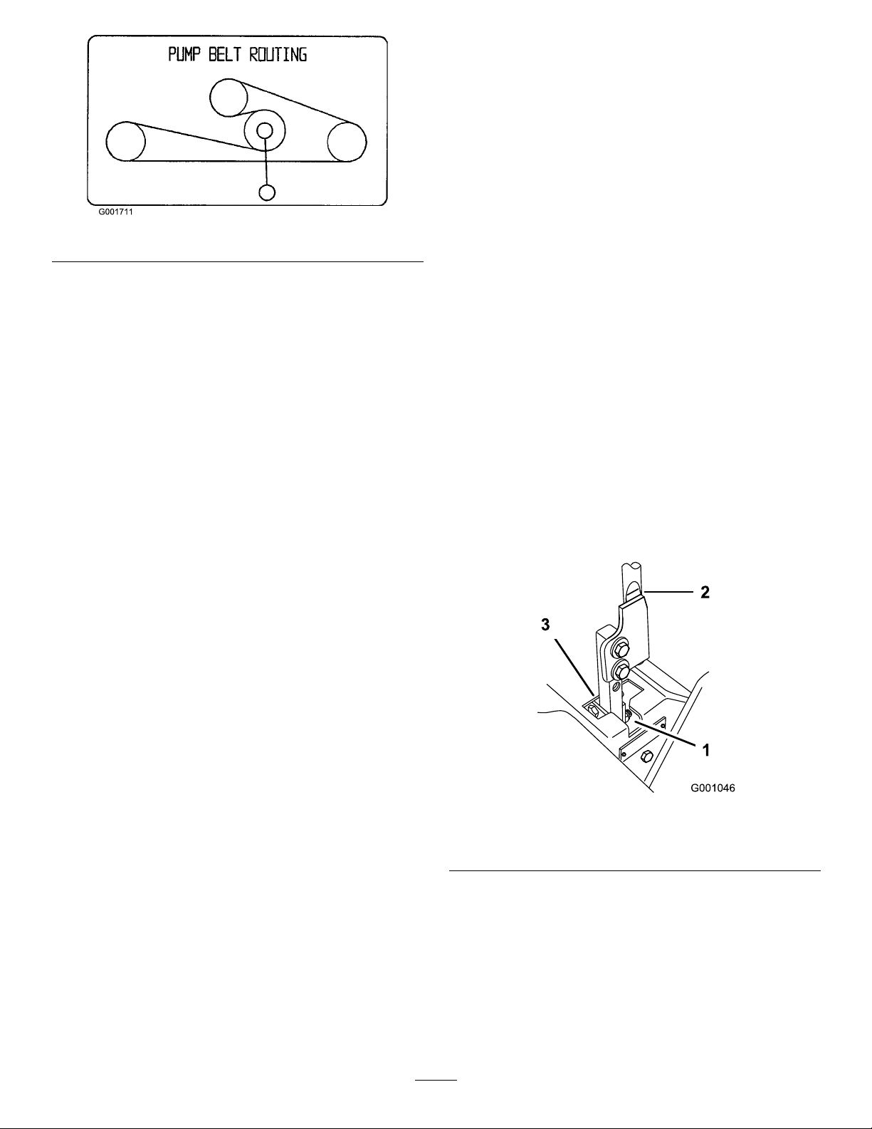
Figure50
3.Installnewbeltaroundengineandhydropump
pulleys(Figure50).
4.Pullspringloadedidlerdownandalignbelow
tractionbelt.Releasethepressureonthespring
loadedidler(Figure50).
ControlsSystem
Maintenance
AdjustingtheControlHandle
NeutralPosition
Ifmotioncontrolleversdonotalign,ormoveeasilyinto
theconsolenotch,adjustmentisrequired.Adjusteach
lever,springandrodseparately.
Note:Motioncontrolleversmustbeinstalledcorrectly.
SeeInstallingtheMotionControlLeversinthesetup
instructions.
1.DisengagethePTO,movethemotioncontrollevers
totheneutrallockedpositionandsettheparking
brake.
2.Stoptheengine,removethekey,andwaitforall
movingpartstostopbeforeleavingtheoperating
position.
3.Unlatchtheseatandtilttheseatforward.
4.Beginwitheithertheleftorrightmotioncontrol
lever.
5.Movethelevertotheneutralpositionbutnotlocked
(Figure51).
Figure51
1.Neutrallockedposition3.Neutralposition
2.Controllever
6.Pulltheleverbackuntiltheclevispin(onarm
belowpivotshaft)contactstheendoftheslot(just
beginningtoputpressureonthespring)(Figure51).
7.Checkwherethecontrolleverisrelativetonotchin
console(Figure51).Itshouldbecenteredallowing
levertopivotoutwardtotheneutrallockposition.
8.Ifadjustmentisneeded,loosenthenutandjamnut
againsttheyoke(Figure52).
38
Page 39
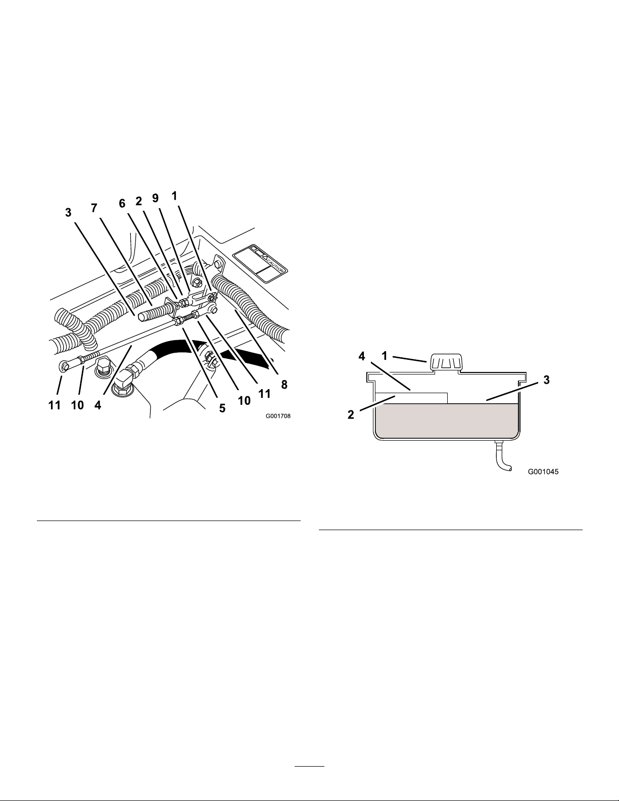
9.Applyslightrearwardpressureonthemotion
controllever,turntheheadoftheadjustmentbolt
intheappropriatedirectionuntilthecontrolleveris
centeredintheneutrallockposition(Figure52).
HydraulicSystem
Maintenance
Note:Keepingrearwardpressureontheleverwill
keepthepinattheendoftheslotandallowthe
adjustmentbolttomovethelevertotheappropriate
position.
10.Tightenthenutandjamnut(Figure52).
11.Repeatfortheoppositesideofthemachine.
CheckingtheHydraulicFluid
ServiceInterval:Aftertherst8hours
Every25hours
FluidType:Mobil115W-50syntheticmotoroilor
equivalentsyntheticoil.
Important:Useoilspeciedorequivalent.Other
uidscouldcausesystemdamage.
HydraulicSystemOilCapacity:67oz.(2.0l)
Note:Therearetwowaysofcheckingthehydraulicoil.
Oneiswhentheoiliswarmandoneiswhentheoilis
cold.Thebafeinsidethetankhastwolevelsdepending
iftheoiliswarmorcold.
1.Positionthemachineonalevelsurfaceandsetthe
parkingbrake.
2.Cleantheareaaroundllerneckofhydraulictank
(Figure53).
Figure52
1.Clevispininslot7.Spring
2.Nutagainstyoke
3.Adjustmentbolt9.Y oke
4.Pumprod10.Locknut
5.Doublenuts11.Balljoint
6.Jamnut
8.Pivotshaft
Figure53
1.Cap3.Colduidlevel-full
2.Bafe4.Hotuidlevel-full
3.Removethecapfromthellerneck.Lookinsideto
checkifthereisuidinthereservoir(Figure53).
4.Ifthereisnouid,adduidtothereservoiruntilit
reachesthecoldlevelofthebafe.
5.Runthemachineatlowidlefor15minutestoallow
anyairtopurgeoutofthesystemandwarmthe
uid.RefertoStartingandStoppingtheEnginein
Operation,page12.
6.Rechecktheuidlevelwhiletheuidiswarm.The
uidshouldbebetweencoldandhot.
7.Ifrequired,adduidtothehydraulictank.
Note:Theuidlevelshouldbetothetopofthehot
levelofthebafe,whentheuidishot(Figure53).
8.Installcaponllerneck.
39
Page 40
Hydraulicuidescapingunderpressurecan
penetrateskinandcauseinjury.
•Ifhydraulicuidisinjectedintotheskin
itmustbesurgicallyremovedwithinafew
hoursbyadoctorfamiliarwiththistypeof
injury.Gangrenemayresultifthisisnot
done.
•Keepbodyandhandsawayfrompinhole
leaksornozzlesthatejecthighpressure
hydraulicuid.
•Usecardboardorpapertondhydraulic
leaks.
•Safelyrelieveallpressureinthehydraulic
systembeforeperforminganyworkonthe
hydraulicsystem.
•Makesureallhydraulicuidhosesand
linesareingoodconditionandallhydraulic
connectionsandttingsaretightbefore
applyingpressuretohydraulicsystem.
Figure54
1.Hydrauliclter
4.Applyathincoathydrouidtotherubbergasketon
thereplacementlter(Figure55).
ReplacingtheHydraulicFilter
andOil
ServiceInterval:Aftertherst25hours
Yearly
Usesummerlterabove32°F(0°C)
Usewinterlterbelow32°F(0°C)
1.DisengagethePTO,movethemotioncontrollevers
totheneutrallockedpositionandsettheparking
brake.
2.Stoptheengine,removethekey,andwaitforall
movingpartstostopbeforeleavingtheoperating
position.
Important:Donotsubstituteautomotiveoil
lterorseverehydraulicsystemdamagemay
result.
3.Placedrainpanunderlter,removetheoldlter
andwipethelteradaptergasketsurfaceclean
(Figure54).
Figure55
1.Hydrauliclter
2.Gasket
3.Adapter
5.Installthereplacementhydrauliclterontothelter
adapter.Donottighten.
6.Fillthehydraulictankwithhydraulicuiduntilthe
uidoverowsthelterandthenturntheoillter
clockwiseuntiltherubbergasketcontactsthelter
adapter,thentightenthelteranadditional1/2turn
(Figure55).
7.Cleanupanyspilleduid.
8.Adduidtothecoldlevelofthebafeinthe
hydraulictank.
9.Starttheengineandletitrunforabouttwominutes
topurgeairfromthesystem.Stoptheengineand
checkforleaks.Ifoneorbothwheelswillnotdrive,
referBleedingHydraulicSystem.
10.Rechecktheuidlevelwhiletheuidiswarm.The
uidshouldbebetweencoldandhot.
11.Ifrequired,adduidtothehydraulictank.Donot
overll.
40
Page 41

BleedingtheHydraulicSystem
SettingtheHydraulicPump
Thetractionsystemisselfbleeding,however,itmaybe
necessarytobleedthesystemifuidischangedorafter
workisperformedonthesystem.
1.Raiserearofthemachinesowheelsareoffthe
groundandsupportwithjackstands.
2.Starttheengineandrunatlowidlespeed.Engage
theleverandtractionononesideandspinthewheel
byhand.
3.Whenthewheelbeginstospinonitsown,keepit
engageduntilwheeldrivessmoothly.(minimum
2minutes)
4.Checkhydraulicuidlevelandaddasrequiredto
maintainproperlevel.
5.Repeatthisprocedureontheoppositewheel.
CheckingtheHydraulicHoses
ServiceInterval:Every100hours
Checkthehydraulichosesforleaks,loosettings,
kinkedlines,loosemountingsupports,wear,weather
andchemicaldeterioration.Makenecessaryrepairs
beforeoperating.
Note:Keepareasaroundthehydraulicsystemclean
fromgrassanddebrisbuildup.
NeutralPosition
Note:Adjustthehandleneutralrst.Thatneedstobe
correctbeforethefollowingadjustmentcanbemade.
Mechanicalorhydraulicjacksmayfailto
supportmachineandcauseaseriousinjury.
•Usejackstandwhensupportingmachine.
•Donotusehydraulicjacks.
Enginemustberunningsomotioncontrol
adjustmentcanbeperformed.Contactwith
movingpartsorhotsurfacesmaycause
personalinjury.
Keephands,feet,face,clothingandotherbody
partsawayfromrotatingparts,muferand
otherhotsurfaces.
Thisadjustmentmustbemadewithdrivewheelsturning.
1.Raisetheframeandusejackstandstoholdupthe
machinesodrivewheelscanrotatefreely.
Hydraulicuidescapingunderpressurecan
penetrateskinandcauseinjury.
•Ifhydraulicuidisinjectedintotheskin
itmustbesurgicallyremovedwithinafew
hoursbyadoctorfamiliarwiththistypeof
injury.Gangrenemayresultifthisisnot
done.
•Keepbodyandhandsawayfrompinhole
leaksornozzlesthatejecthighpressure
hydraulicuid.
•Usecardboardorpapertondhydraulic
leaks.
•Safelyrelieveallpressureinthehydraulic
systembeforeperforminganyworkonthe
hydraulicsystem.
•Makesureallhydraulicuidhosesand
linesareingoodconditionandallhydraulic
connectionsandttingsaretightbefore
applyingpressuretohydraulicsystem.
2.Unlatchtheseat,tilttheseatforwardanddisconnect
electricalconnectorfromtheseatsafetyswitch.
3.Temporarilyinstallajumperwireacrossterminals
inthewiringharnessconnector.
4.Slidetheseatforward,disconnecttheproprodand
tilttheseatfullyforward.
SettingtheRight-handHydraulicPump
NeutralPosition
1.Starttheengine,openthethrottle1/2wayand
releasetheparkingbrake.RefertoStartingand
StoppingtheEngineinOperation,page12.
Note:Themotioncontrollevermustbeinneutral
whilemakinganyadjustments.
2.Loosenthelocknutagainsttheballjoint.
3.Adjustthepumprodlengthbyrotatingthedouble
nutsonrod,intheappropriatedirection,until
thewheelisstillorslightlycreepinginreverse
(Figure56).
41
Page 42
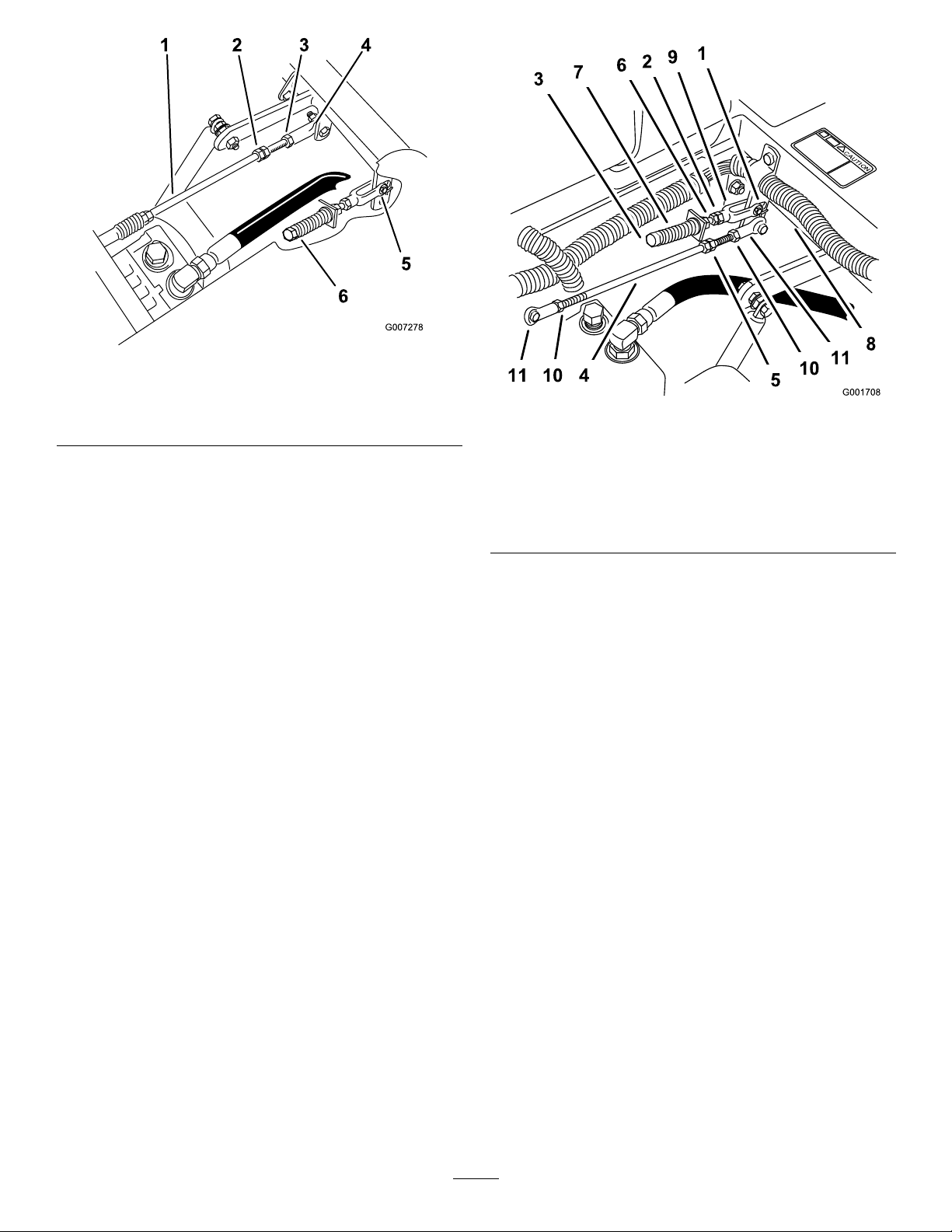
Figure56
1.Pumprod4.Balljoint
2.Doublenuts5.Yoke
3.Locknut6.Adjustmentbolt
4.Movethemotioncontrolleverforwardandreverse,
thenbacktoneutral.Thewheelmuststopturning
orslightlycreepinreverse.
5.Openthethrottletofast.Makesurethewheel
remainsstoppedorslightlycreepsinreverse,adjust
ifnecessary.
6.Tightenthelocknutattheballjoint(Figure56).
Figure57
1.Clevispininslot7.Spring
2.Nutagainstyoke
3.Adjustmentbolt9.Y oke
4.Pumprod10.Locknut
5.Doublenuts11.Balljoint
6.Jamnut
8.Pivotshaft
2.Starttheengine,openthrottle1/2way,andrelease
parkingbrake.RefertoStartingandStoppingthe
EngineinOperation,page12.
SettingtheLeft-handHydraulicPump
NeutralPosition
1.Loosenthelocknutsattheballjointsonthepump
controlrod(Figure57).
Note:Themotioncontrollevermustbeinneutral
whilemakinganyadjustments.
Note:Thefrontnutonthepumprodhasleft-hand
threads.
3.Adjustthepumprodlengthbyrotatingthedouble
nutsonrod,intheappropriatedirection,untilwheel
isstillorslightlycreepsinreverse(Figure57).
4.Movethemotioncontrolleverforwardandreverse,
thenbacktoneutral.Thewheelmuststopturning
orslightlycreepinreverse.
5.Openthethrottletofast.Makesurethewheel
remainsstoppedorslightlycreepsinreverse,adjust
ifnecessary.
6.Tightenthelocknutsattheballjoints(Figure57).
42
Page 43

MowerDeck
Electricalsystemwillnotperformpropersafety
shutoffwithjumperwireinstalled.
•Removejumperwirefromwireharness
connectorandplugconnectorintoseat
switchwhenadjustmentiscompleted.
•Neveroperatethisunitwithjumperinstalled
andseatswitchbypassed.
7.Afterbothpumpneutralsareset,shutoffthe
machine.
8.Removethejumperwirefromthewireharness
connectorandplugtheconnectorintotheseat
switch.
9.Installtheseatrodandlowertheseatintoposition.
10.Removethejackstands.
Maintenance
LevelingtheMoweratThree
Positions
Important:Thereareonlythreemeasuring
positionsneededtolevelthemower.
SettingUptheMachine
1.Positionmoweronaatsurface.
2.DisengagethePTO,movethemotioncontrollevers
totheneutrallockedpositionandsettheparking
brake.
3.Stoptheengine,removethekey,andwaitforall
movingpartstostopbeforeleavingtheoperating
position.
4.Checktirepressureofallfourtires.Ifneeded,adjust
to13psi(90kPa)
5.Lowerthemowertothe3inch(76mm)height-of-cut
position.
6.Inspectthefourchains.Thechainsneedtohave
tension.
Note:Adjusttherearchainstothetopoftheslot,
wheretheyareattachedtothemower.
•Ifonerearchainisloose,lower(loosen)thefront
supportarmonthesameside.RefertoAdjusting
theFront-to-RearMowerPitch.
•Ifonefrontchainisloose,raise(tighten)the
frontsupportarmforthatchain.Referto
AdjustingtheFront-to-RearMowerPitch.
LevelingtheMowerSide-to-Side
1.Positiontherightbladeside-to-side(Figure58).
43
Page 44
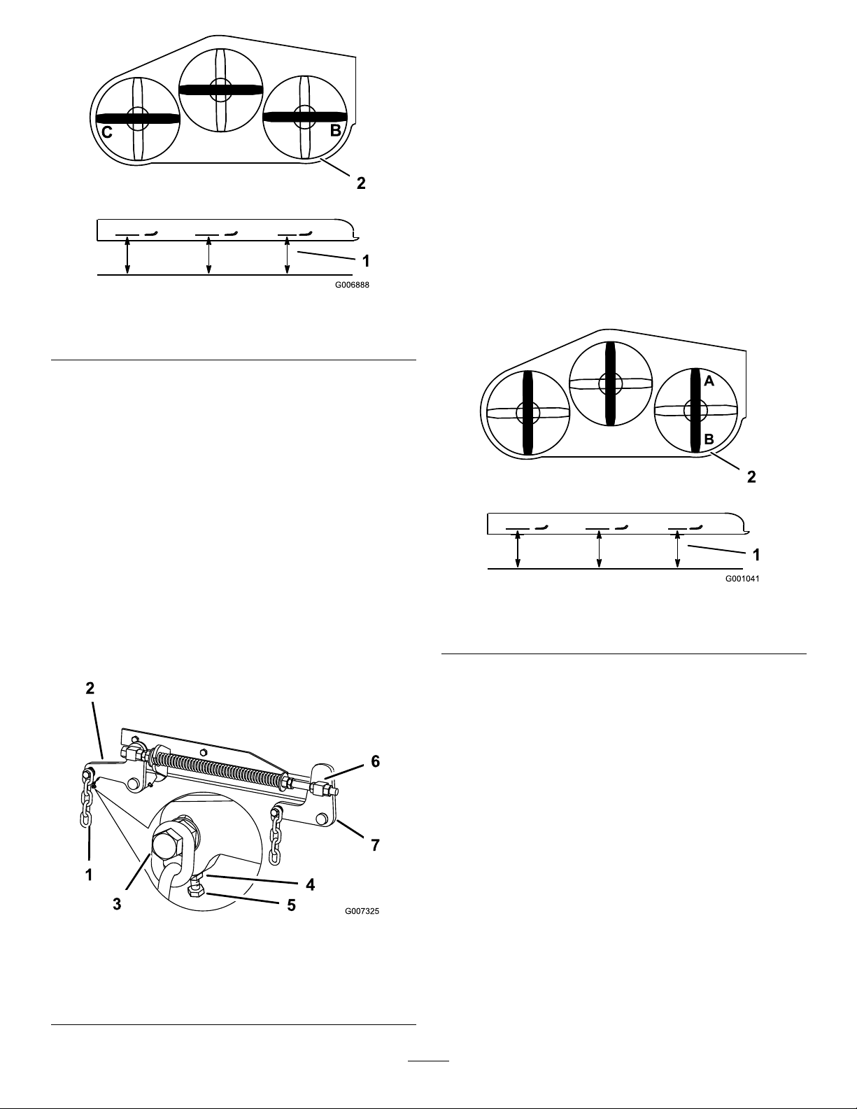
Figure58
1.Measureherefromblade
tohardsurface
2.MeasureatBandC
2.MeasuretherightbladeattheBlocation,froma
levelsurfacetothecuttingedgeofthebladetip
(Figure58).
3.Recordthismeasurement.Thismeasurementneeds
tobe3-1/8to3-1/4inches.
8.Loosenthejamnutundertherearsupportarmand
adjusttheadjustmentbolttogetameasurementof
3-1/8to3-1/4inches(80to83mm)(Figure59).
Note:Itisrecommendedthatbothsidesofthe
mowerareadjustedthesamedistance.
9.Tightenthejamnutundertherearsupportarm
andtightentheboltsecuringthechaintotherear
supportarm.
10.Adjusttheoppositesideifneeded.
AdjustingtheFront-to-RearMower
Pitch
1.Positiontherightbladefront-to-rear(Figure60).
4.Positiontheleftbladeside-to-side(Figure58).
5.MeasuretheleftbladeattheClocation(Figure58),
fromalevelsurfacetothecuttingedgeoftheblade
tip.
6.Recordthismeasurement.Thismeasurementneeds
tobe3-1/8to3-1/4inches(80to83mm).
7.IfthemeasurementsatpositionsBorCarenot
correct,loosentheboltattachingtherearchainto
therearsupportarm(Figure59).
Figure59
1.Rearchain5.Adjustmentbolt
2.Rearsupportarm6.Frontswivel
3.Bolt7.Frontsupportarm
4.JamNut
Figure60
1.Measureherefromblade
tohardsurface
2.MeasureatAandB
2.MeasuretherightbladeattheAlocation,froma
levelsurfacetothecuttingedgeofthebladetip
(Figure60).
3.Recordthismeasurement.
4.MeasuretherightbladeattheBlocation,froma
levelsurfacetothecuttingedgeofthebladetip
(Figure60).
5.Recordthismeasurement.
6.Themowerbladeshouldbea1/4to3/8inch
(6to10mm)loweratpositionAthanatposition
B(Figure60).Ifitisnotcorrect,proceedtothe
followingsteps.
Note:Bothofthefrontswivelsneedtobeadjusted
thesameamounttomaintainequalchaintension.
7.Loosenthefrontswiveljamnuts,atthefrontof
therightandleftswivels,approximatelya1/2inch
(13mm)(Figure59).
44
Page 45
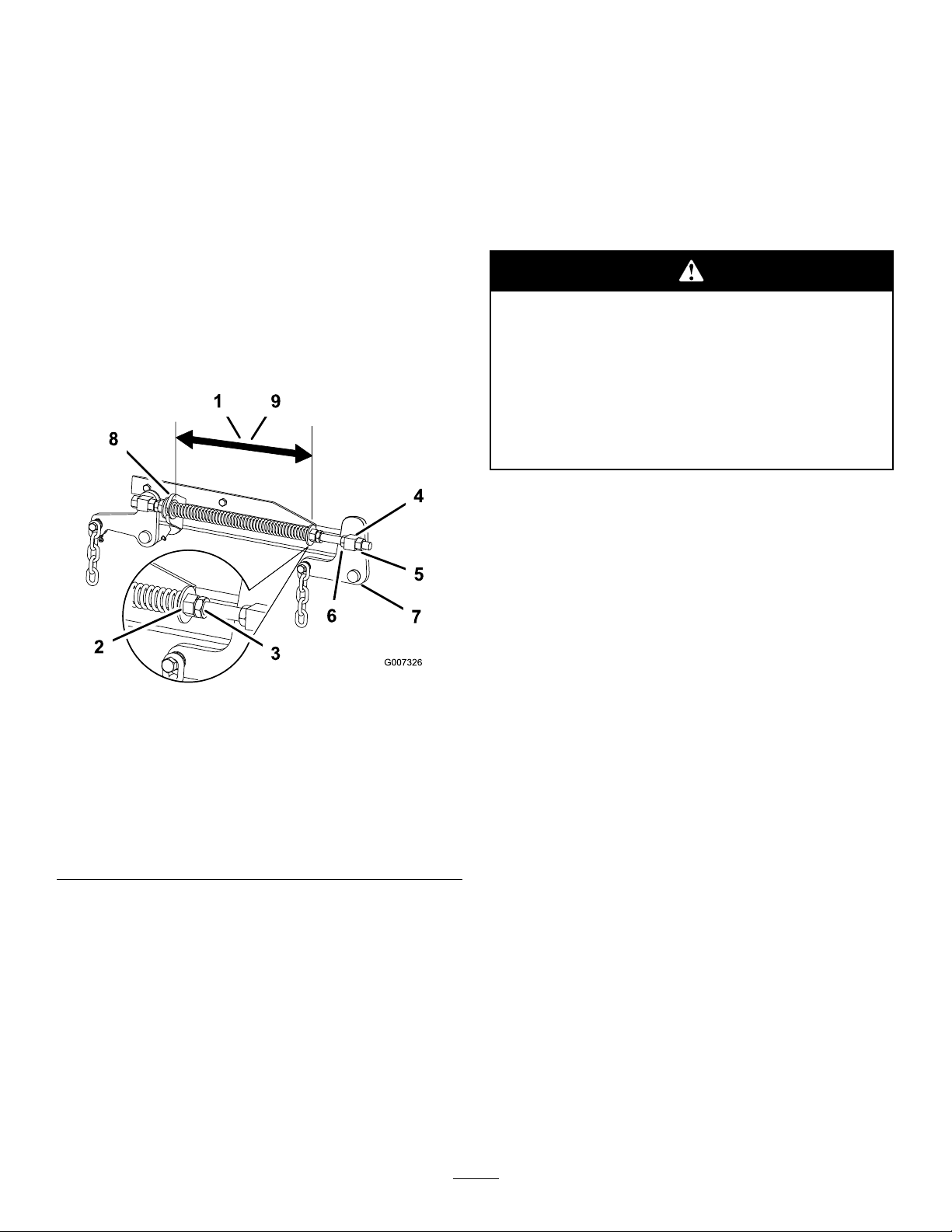
8.Adjusttheliftnutsonboththeleftandtheright
sideofthemachinetoachieve1/4to3/8inch
(6to10mm)lowerinfrontatAthanintherearat
B(Figure59).
9.Tightenbothswiveljamnutsagainstthefrontswivel
tolocktheheight.
10.Checktomakesurethereisequaltensiononthe
chainsandadjustagainifneeded.
AdjustingtheCompressionSpring
1.Raisethemowerliftlevertothetransportposition.
shreddingthegrassblades.Tearingandshreddingturns
grassbrownattheedges,whichslowsgrowthand
increasesthechanceofdisease.
Checkthecutterbladesdailyforsharpness,andforany
wearordamage.Filedownanynicksandsharpenthe
bladesasnecessary.Ifabladeisdamagedorworn,
replaceitimmediatelywithagenuineTororeplacement
blade.Forconvenientsharpeningandreplacement,you
maywanttokeepextrabladesonhand.
2.Checkthedistancebetweenthetwolargewashers,
itneedstobe11-1/8inches(28.2cm)for52inch
mowerdecksand10-1/2inches(26.7cm)for60
inchmowerdecks(Figure61).
Figure61
1.11–1/8inch(28.2cm)
betweenthelargewashers
for52inchmowerdecks
2.Frontnut7.Frontsupportarm
3.Springjamnut
4.Frontswivel
5.Swiveljamnut
6.Liftnut
8.Largewasher
9.10-1/2inch(26.7cm)
betweenthelargewashers
for60inchmowerdecks
Awornordamagedbladecanbreak,anda
pieceofthebladecouldbethrownintothe
operator’sorbystander’sarea,resultingin
seriouspersonalinjuryordeath.
•Inspectthebladeperiodicallyforwearor
damage.
•Replaceawornordamagedblade.
BeforeInspectingorServicingthe
Blades
1.Parkthemachineonalevelsurface,disengagethe
bladecontrol(PTO),andsettheparkingbrake.
2.TurntheignitionkeytoOffandremovethekey.
3.Disconnectthesparkplugwire(s)fromthespark
plug(s).
InspectingtheBlades
ServiceInterval:Beforeeachuseordaily
1.Inspectthecuttingedges(Figure62).
Iftheedgesarenotsharporhavenicks,removeand
sharpentheblades.RefertoSharpeningtheBlades.
3.Adjustthisdistance,bylooseningthespringjam
nutandturningthenutinfrontofeachspring
(Figure61).Turningthenutclockwisewillshorten
thespring;counter-clockwisewilllengthenthe
spring.
4.Lockthenutintopositionbytighteningthespring
jamnut(Figure61).
ServicingtheCuttingBlades
Maintainsharpbladesthroughoutthecuttingseason
becausesharpbladescutcleanlywithouttearingor
45
Page 46
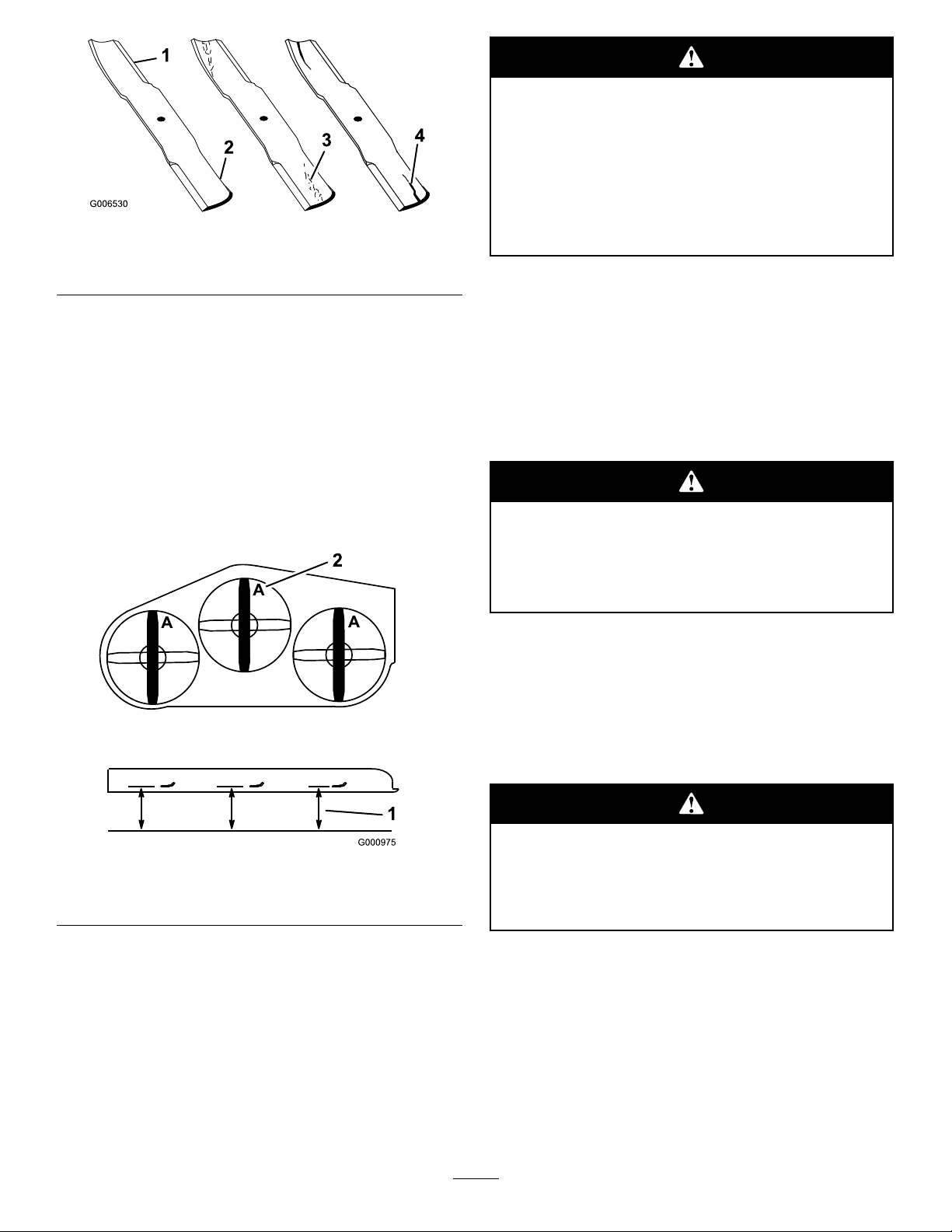
Abladethatisbentordamagedcouldbreak
apartandcouldseriouslyinjureorkillyouor
bystanders.
•Alwaysreplacebentordamagedbladewith
anewblade.
Figure62
1.CuttingEdge3.Wear/slotForming
2.CurvedArea4.Crack
2.Inspecttheblades,especiallythecurvedarea
(Figure62).
Ifyounoticeanydamage,wear,oraslotformingin
thisarea(Figure62),immediatelyinstallanewblade.
CheckingforBentBlades
1.Rotatethebladesuntiltheendsfaceforwardand
backward(Figure63).Measurefromalevelsurface
tothecuttingedge,positionA,oftheblades
(Figure63).Notethisdimension.
•Neverleorcreatesharpnotchesinthe
edgesorsurfacesofblade.
RemovingtheBlades
Bladesmustbereplacedifasolidobjectishit,ifthe
bladeisoutofbalanceorisbent.T oensureoptimum
performanceandcontinuedsafetyconformanceof
themachine,usegenuineTororeplacementblades.
Replacementbladesmadebyothermanufacturersmay
resultinnon-conformancewithsafetystandards.
Contactwithasharpbladecancauseserious
injury.
Wearglovesorwrapsharpedgesoftheblade
witharag.
1.Holdthebladeendusingaragorthickly-padded
glove.
Figure63
1.Measureherefromblade
tohardsurface
2.PositionA
2.Rotatetheoppositeendsofthebladesforward.
3.Measurefromalevelsurfacetothecuttingedgeof
thebladesatthesamepositionasinstep1above.
Thedifferencebetweenthedimensionsobtainedin
steps1and2mustnotexceed1/8inch(3mm).If
thisdimensionexceeds1/8inch(3mm),theblade
isbentandmustbereplaced;refertoRemovingthe
BladesandInstallingtheBlades.
2.Removethebladebolt,springdiskandbladefrom
thespindleshaft(Figure66).
SharpeningtheBlades
Whensharpeningblade,piecesofbladecould
bethrownandcauseseriousinjury.
Wearpropereyeprotectionwhensharpening
blade.
1.Usealetosharpenthecuttingedgeatbothends
oftheblade(Figure64).Maintaintheoriginalangle.
Thebladeretainsitsbalanceifthesameamountof
materialisremovedfrombothcuttingedges.
46
Page 47
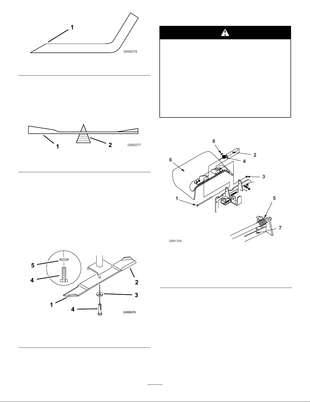
1.Sharpenatoriginalangle
Figure64
ReplacingtheGrassDeector
Anuncovereddischargeopeningcouldallow
thelawnmowertothrowobjectsinthe
operator’sorbystander’sdirectionandresult
inseriousinjury.Also,contactwiththeblade
couldoccur.
2.Checkthebalanceofthebladebyputtingitona
bladebalancer(Figure65).Ifthebladestaysina
horizontalposition,thebladeisbalancedandcanbe
used.Ifthebladeisnotbalanced,lesomemetaloff
theendofthesailareaonly(Figure66).Repeatthis
procedureuntilthebladeisbalanced.
Figure65
1.Blade2.Balancer
InstallingtheBlades
1.Installthebladeontothespindleshaft(Figure66).
Important:Thecurvedpartoftheblademust
bepointingupwardtowardtheinsideofthe
mowertoensurepropercutting.
•Neveroperatethelawnmowerunlessyou
installacoverplate,amulchplate,oragrass
chuteandcatcher.
•Makesurethegrassdeectorisinthedown
position.
1.Removethelocknut,bolt,springandspacerholding
thedeectortothepivotbrackets(Figure67).
2.Installthespringdiskandbladebolt.Thespring
diskconemustbeinstalledtowardthebolthead
(Figure66).
Figure66
1.SailAreaofBlade
2.Blade
3.SpringDisk
4.BladeBolt
5.ConeTowardsBoltHead
3.Torquethebladeboltto85-110ft-lb(115-150N⋅m).
Figure67
1.Bolt
2.Spacer6.GrassDeector
3.Locknut7.Placebehinddeckedge
4.Spring8.Hookendofspring
5.Springinstalled
beforeinstallingbolt
2.Removethedamagedorworngrassdeector.
3.Installtheboltandnut.
4.PlacetheJhookendofthespringaroundthegrass
deector(Figure67).
Important:Thegrassdeectormustbeableto
lowerdownintoposition.Liftthedeectorup
totestthatitlowersintothefulldownposition.
47
Page 48

Cleaning
CleaningUndertheMower
ServiceInterval:Beforeeachuseordaily
Removethegrassbuildupunderthemowerdaily.
1.DisengagethePTO,movethemotioncontrollevers
totheneutrallockedpositionandsettheparking
brake.
Storage
1.Disengagethepowertakeoff(PTO),settheparking
brakeandturntheignitionkeytooff.Removespark
plugwire.Removethekey.
2.Removegrassclippings,dirt,andgrimefromthe
externalpartsoftheentiremachine,especiallythe
engineandhydraulicsystem.Cleandirtandchaff
fromtheoutsideoftheengine’scylinderheadns
andblowerhousing.
2.Stoptheengine,removethekey,andwaitforall
movingpartstostopbeforeleavingtheoperating
position.
3.Raisethemowertothetransportposition.
WasteDisposal
Engineoil,batteries,hydraulicoil,andenginecoolant
arepollutantstotheenvironment.Disposeofthese
accordingtoyourstateandlocalregulations.
Important:Youcanwashthemachinewith
milddetergentandwater.Donotpressure
washthemachine.Avoidexcessiveuseof
water,especiallynearthecontrolpanel,engine,
hydraulicpumpsandmotors.
3.Servicetheaircleaner;refertoServicingtheAir
CleanerinEngineMaintenance,page27.
4.Greaseandoilthemachine;refertoGreasingand
LubricationinLubrication,page25.
5.Changethecrankcaseoil;refertoServicingthe
EngineOilinEngineMaintenance,page27.
6.Changethehydrauliclter;refertoServicingthe
HydraulicSysteminHydraulicSystemMaintenance,
page39.
7.Checkthetirepressure;refertoCheckingtheTire
PressureinDriveSystemMaintenance,page33.
8.Chargethebattery;refertoServicingtheBatteryin
ElectricalSystemMaintenance,page31.
9.Scrapeanyheavybuildupofgrassanddirtfromthe
undersideofthemower,thenwashthemowerwith
agardenhose.
Note:RunthemachinewiththePTOengaged
andtheengineathighidlefor2to5minutesafter
washing.
10.Checktheconditionoftheblades.RefertoServicing
theCuttingBlades.
11.Preparethemachineforstoragewhennon-use
occursover30days.Preparemachineforstorage
asfollows.
A.Addapetroleumbasedstabilizer/conditionerto
fuelinthetank.Followmixinginstructionsfrom
stabilizermanufacture.Donotuseanalcohol
basedstabilizer(ethanolormethanol).
Note:Afuelstabilizer/conditionerismost
effectivewhenmixedwithfreshgasolineand
usedatalltimes.
B.Runenginetodistributeconditionedfuelthrough
thefuelsystem(5minutes).
48
Page 49

C.Stopengine,allowtocoolanddrainthefuel
tank;refertoServicingtheFuelTankinFuel
SystemMaintenance,page30.
D.Restartengineandrunituntilitstops.
E.Choketheengine.Startandrunengineuntilit
willnotstart.
F.Disposeoffuelproperly .Recycleasperlocal
codes.
Important:Donotstorestabilizer/conditioned
gasolineover90days.
12.Removethesparkplug(s)andcheckitscondition;
refertoServicingtheSparkPluginEngine
Maintenance,page27.Withthesparkplug(s)
removedfromtheengine,pourtwotablespoonsof
engineoilintothesparkplughole.Nowusethe
startertocranktheengineanddistributetheoil
insidethecylinder.Installthesparkplug(s).Donot
installthewireonthesparkplug(s).
13.Checkandtightenallbolts,nuts,andscrews.Repair
orreplaceanypartthatisdamagedordefective.
14.Paintallscratchedorbaremetalsurfaces.Paintis
availablefromyourAuthorizedServiceDealer.
15.Storethemachineinaclean,drygarageorstorage
area.Removethekeyfromtheignitionswitchand
keepitoutofreachofchildrenorotherunauthorized
users.Coverthemachinetoprotectitandkeepit
clean.
49
Page 50

Troubleshooting
Problem
Starterdoesnotcrank
Enginewillnotstart,startshard,orfails
tokeeprunning.
Enginelosespower.
PossibleCauseCorrectiveAction
1.Bladecontrol(PTO)isengaged.1.Movebladecontro(PTO)to
2.Parkingbrakeisnoton.
3.Operatorisnotseated.3.Sitontheseat.
4.Batteryisdead.
5.Electricalconnectionsarecorrodedor
loose.
6.Fuseisblown.
7.Relayorswitchisdefective.7.ContactanAuthorizedServiceDealer.
1.Fueltankisempty.
2.Aircleanerisdirty.
3.Dirtinthefuellter.3.Replacethefuellter.
4.Dirt,water,orstalefuelisinthefuel
system.
1.Engineloadisexcessive.1.Reducethegroundspeed.
2.Aircleanerisdirty.
3.Oillevelinthecrankcaseislow .
4.Coolingnsandairpassagesabove
theengineareplugged.
5.Ventholeinthefuelcapisplugged.5.Cleanorreplacethefuelcap.
6.Dirtinthefuellter.6.Replacethefuellter.
7.Dirt,water,orstalefuelisinthefuel
system.
disengaged.
2.Settheparkingbrake.
4.Chargethebattery .
5.Checktheelectricalconnectionsfor
goodcontact.
6.Replacefuse.
1.Fillfueltankwithfuel.
2.Cleanorreplacetheaircleaner
element.
4.ContactanAuthorizedServiceDealer.
2.Cleantheaircleanerelement.
3.Addoiltothecrankcase.
4.Removetheobstructionfromthe
coolingnsandairpassages.
7.ContactanAuthorizedServiceDealer.
Engineoverheats.
Machinedoesnotdrive.
Abnormalvibration.
1.Engineloadisexcessive.1.Reducethegroundspeed.
2.Oillevelinthecrankcaseislow .
3.Coolingnsandairpassagesabove
theengineareplugged.
1.Bypassvalveisnotclosedtight.1.Tightenthebypassvalve.
2.Driveorpumpbeltisworn,looseor
broken.
3.Driveorpumpbeltisoffapulley.3.Changethebelt.
4.Brokenormissingidlerspring.4.Replacethespring.
5.Hydraulicuidlevelislowortoohot.5.Addhydraulicuidtoreservoirorletit
1.Cuttingblade(s)is/arebentor
unbalanced.
2.Blademountingboltisloose.2.Tightentheblademountingbolt.
3.Enginemountingboltsareloose.3.Tightentheenginemountingbolts.
4.Looseenginepulley,idlerpulley,or
bladepulley .
5.Enginepulleyisdamaged.
6.Bladespindleisbent.
7.Motormountislooseorworn.
2.Addoiltothecrankcase.
3.Removetheobstructionfromthe
coolingnsandairpassages.
2.Changethebelt.
cooldown.
1.Installnewcuttingblade(s).
4.Tightentheappropriatepulley.
5.ContactanAuthorizedServiceDealer.
6.ContactanAuthorizedServiceDealer.
7.ContactanAuthorizedServiceDealer.
50
Page 51

Problem
PossibleCauseCorrectiveAction
Unevencuttingheight.
Bladesdonotrotate.
1.Blade(s)notsharp.1.Sharpentheblade(s).
2.Cuttingblade(s)is/arebent.2.Installnewcuttingblade(s).
3.Mowerisnotlevel.
4.Undersideofmowerisdirty .4.Cleantheundersideofthemower.
5.Tirepressureisnotcorrect.5.Adjustthetirepressure.
6.Bladespindlebent.
1.Drivebeltisworn,looseorbroken.
2.Drivebeltisoffpulley.
3.Deckbeltisworn,looseorbroken.3.Installnewdeckbelt.
4.Deckbeltisoffpulley.
5.Brokenormissingidlerspring.5.Replacethespring.
3.Levelmowerfromside-to-sideand
front-to-rear.
6.ContactanAuthorizedServiceDealer.
1.Checkthebelttension.
2.Installdrivebeltandcheckadjusting
shaftsandbeltguidesforcorrect
position.
4.Installdeckpulleyandchecktheidler
pulley,idlerarmandspringforcorrect
positionandfunction.
51
Page 52
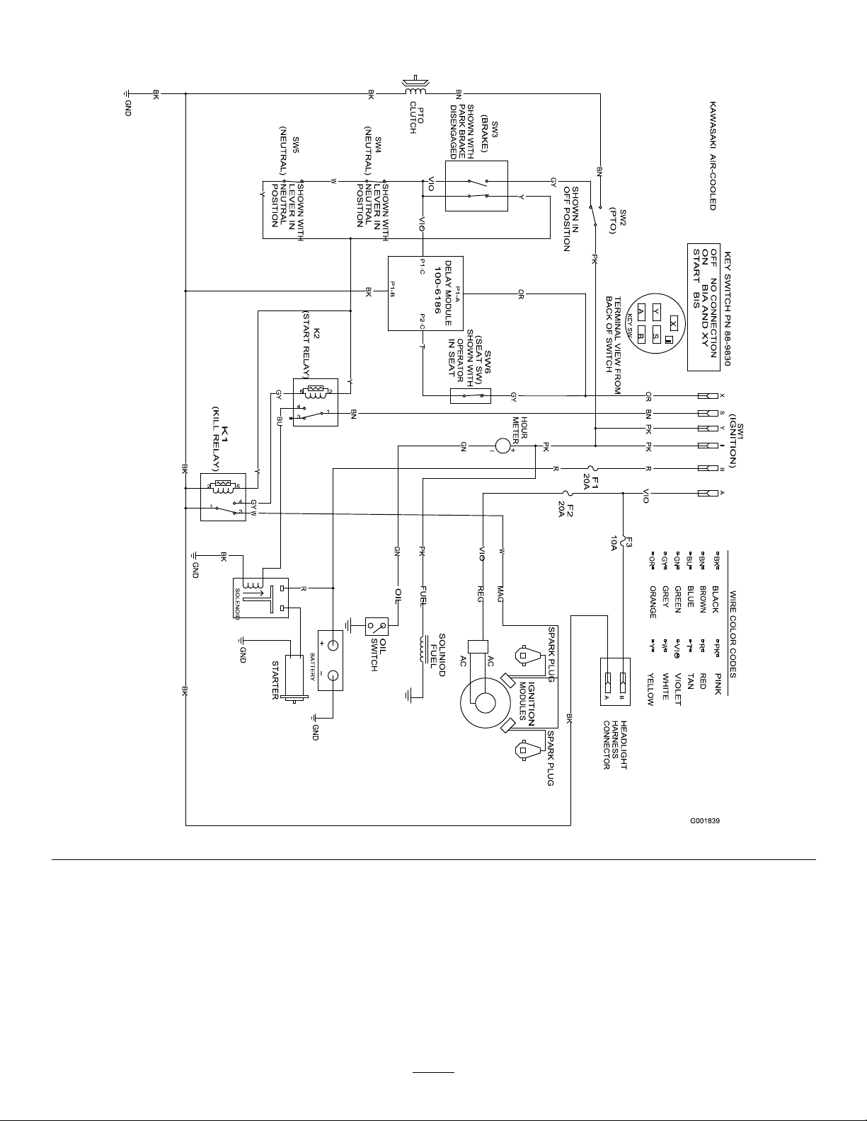
Schematics
WireDiagram(Rev.A)
52
Page 53

Notes:
53
Page 54

Notes:
54
Page 55

Notes:
55
Page 56

Landscape
Contractor
Equipment (LCE)
The Toro Total Coverage Guarantee
A Limited Warranty
Conditions and Products Covered
The Toro® Company and its afliate, Toro Warranty Company, pursuant to an
agreement between them, jointly promise to repair the listed Toro Products if
defective in materials or workmanship. The following time periods apply from
the date of purchase:
This warranty applies to:
•
ProLine Mid-Size Mowers and Attachments
•
Z Master Mid-Mount ZRTs and Attachments
Components
Traction Unit Frame and Carrier Frame
All Spindles
Engines* and /Hydraulic System
Deck Shells (34 ″ -72 ″ )
Z500 Series Electric Clutch
Remaining Components
* S o m e e n g i n e s u s e d o n T o r o L C E P r o d u c t s a r e w a r r a n t e d b y t h e e n g i n e m a n u f a c t u r e r .
This warranty includes the cost of parts and labor, but you must pay
transportation costs.
Warranty Period
1 year
1 year
2 year
3 years Parts
2 years Labor
2 years
2 years
2 years
1 year
Instructions for Obtaining Warranty Service
If you think that your Toro Product contains a defect in materials or
workmanship, follow this procedure:
1. Contact any Toro Authorized or Master Service Dealer to arrange service at
their dealership. To locate a dealer convenient to you, access our website at
www.Toro.com. You may also call our Toro Customer Care Department
toll free at 888–865–5676 (U.S. Customers) or 888–865–5691 (Canada
customers).
2. Bring the product and your proof of purchase (sales receipt) to the Service
Dealer.
If for any reason you are dissatised with the Service Dealer’s analysis or with
the assistance provided, contact us at:
LCB Customer Service Department
Toro Warranty Company
8111 Lyndale Avenue South
Bloomington, MN 55420-1196
Owner Responsibilities
You must maintain your Toro Product by following the maintenance procedures
described in the operator’s manual. Such routine maintenance, whether
performed by a dealer or by you, is at your expense.
Items and Conditions Not Covered
There is no other express warranty except for special emission system coverage
on some products. This express warranty does not cover the following:
• Cost of regular maintenance service or parts, such as lters, fuel, lubricants,
tune-up parts, blade sharpening, brake and clutch adjustments.
• Any product or part which has been altered or misused or required
replacement or repair due to normal wear, accidents, or lack of proper
maintenance.
• Repairs necessary due to improper fuel, contaminants in the fuel system, or
failure to properly prepare the fuel system prior to any period of non-use
over three months.
• Pickup and delivery charges.
General Conditions
All repairs covered by this warranty must be performed by an Authorized Toro
Service Dealer using Toro approved replacement parts.
Neither The Toro® Company nor Toro Warranty Company is liable for
indirect, incidental or consequential damages in connection with the
use of the Toro Products covered by this warranty, including any
cost or expense of providing substitute equipment or service during
reasonable periods of malfunction or non-use pending completion
of repairs under this warranty.
Some states do not allow exclusions of incidental or consequential
damages, or limitations on how long an implied warranty lasts, so
the above exclusions and limitations may not apply to you.
All implied warranties of merchantability (that the product is t
for ordinary use) and tness for use (that the product is t for
a particular purpose) are limited to the duration of the express
warranty.
This warranty gives you specic legal rights, and you may also have
other rights which vary from state to state.
Countries Other than the United States or Canada
Customers who have purchased Toro products exported from the United States or Canada should contact their Toro Distributor (Dealer) to obtain guarantee
policies for your country, province, or state. If for any reason you are dissatised with your Distributor’s service or have difculty obtaining guarantee information,
contact the Toro importer. If all other remedies fail, you may contact us at Toro Warranty Company.
374-0037 Rev F
 Loading...