

Page 1
Form No. 3355-374 Rev A
Z597-D Z Master® with a 62 or
72 Rear Discharge Mower
Model No. 74280TE —Serial No. 260000001 and Up
Model No. 74281TE —Serial No. 260000001 and Up
Register your product at www.Toro.com Original Instructions (EN)
Page 2
T his spark ignition system complies with Canadian
ICES-002
Introduction
R ead this infor mation carefully to lear n ho w to
operate and maintain y our product properly and
to a v oid injur y and product damag e . Y ou are
responsible for operating the product properly
and safely .
Y ou ma y contact T oro directly at www .T oro .com
for product and accessor y infor mation, help
finding a dealer , or to register y our product.
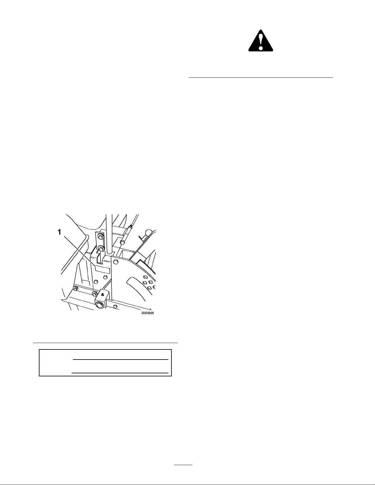
Figure 2
1. Safety alert symbol
T his man ual uses 2 other w ords to highlight
infor mation. Impor tant calls attention to special
mec hanical infor mation and Note emphasizes
g eneral infor mation w or th y of special attention.
Contents
W henev er y ou need ser vice , g en uine T oro par ts ,
or additional infor mation, contact an A uthorized
Ser vice Dealer or T oro Customer Ser vice and ha v e
the model and serial n umbers of y our product
ready . Figure 1 identifies the location of the model
and serial n umbers on the product. W rite the
n umbers in the space pro vided.
Figure 1
1. Model and serial number location
Model No.
Serial No.
T his man ual identifies potential hazards and has
safety messag es identified b y the safety aler t
symbol ( Figure 2 ), whic h signals a hazard that ma y
cause serious injur y or death if y ou do not follo w
the recommended precautions .
Introduction . . . . . . . . . . . . . . . . . . . . . . . . . . . . . . . . . . . . . . . . . . . . . . . . . . . . . . . 2
Safety . . . . . . . . . . . . . . . . . . . . . . . . . . . . . . . . . . . . . . . . . . . . . . . . . . . . . . . . . . . . . . . . . . 4
Safe Operating Practices . . . . . . . . . . . . . . . . . . . . . . 4
T oro Riding Mo w er Safety . . . . . . . . . . . . . . . . . . . 6
Sound Pressure Lev el . . . . . . . . . . . . . . . . . . . . . . . . . . . 6
Sound P o w er Lev el . . . . . . . . . . . . . . . . . . . . . . . . . . . . . . 7
Vibration Lev el . . . . . . . . . . . . . . . . . . . . . . . . . . . . . . . . . . . . 7
Slope Char t . . . . . . . . . . . . . . . . . . . . . . . . . . . . . . . . . . . . . . . . . 8
Safety and Instr uctional Decals . . . . . . . . . . . . 9
Product Ov er view . . . . . . . . . . . . . . . . . . . . . . . . . . . . . . . . . . . . . . . . . . . . . 16
Controls . . . . . . . . . . . . . . . . . . . . . . . . . . . . . . . . . . . . . . . . . . . 16
Operation . . . . . . . . . . . . . . . . . . . . . . . . . . . . . . . . . . . . . . . . . . . . . . . . . . . . . . . . . . 17
Adding Fuel . . . . . . . . . . . . . . . . . . . . . . . . . . . . . . . . . . . . . . 17
Chec king the Engine Oil Lev el . . . . . . . . . . . 18
Switc hing the Fuel T anks . . . . . . . . . . . . . . . . . . . 18
Using the R ollo v er Protection
System (R OPS) . . . . . . . . . . . . . . . . . . 18
T hink Safety First . . . . . . . . . . . . . . . . . . . . . . . . . . . . . . 19
Understanding the A udible
Alar ms . . . . . . . . . . . . . . . . . . . . . . . . . . . . . . 20
Operating the P arking Brak e . . . . . . . . . . . . . . 21
Star ting and Stopping the
Engine . . . . . . . . . . . . . . . . . . . . . . . . . . . . . . 21
Operating the P o w er T ak e Off
(PTO) . . . . . . . . . . . . . . . . . . . . . . . . . . . . . . . 23
T he Safety Interloc k System . . . . . . . . . . . . . . . 23
Dri ving F orw ard or Bac kw ard . . . . . . . . . . . . 24
Stopping the Mac hine . . . . . . . . . . . . . . . . . . . . . . . . 25
Adjusting the Height-of-Cut . . . . . . . . . . . . . . 25
Using the Lift Assist Lev er . . . . . . . . . . . . . . . . . 25
Adjusting the Anti-Scalp
R ollers . . . . . . . . . . . . . . . . . . . . . . . . . . . . . . . 25
P ositioning the Seat . . . . . . . . . . . . . . . . . . . . . . . . . . . 27
Unlatc hing the Seat . . . . . . . . . . . . . . . . . . . . . . . . . . . . 27
Pushing the Mac hine b y Hand . . . . . . . . . . . . 28
T ranspor ting Mac hines . . . . . . . . . . . . . . . . . . . . . . 28
Loading Mac hines . . . . . . . . . . . . . . . . . . . . . . . . . . . . . 29
© 2006—The Toro® Company
8111 Lyndale Avenue South
Bloomington, MN 55420
Contact us at www.Toro.com.
2
Printed in the USA.
All Rights Reserved
Page 3

Using the Z Stand® . . . . . . . . . . . . . . . . . . . . . . . . . . . 30
Operating Tips . . . . . . . . . . . . . . . . . . . . . . . . . . . . . . . . . . 31
Maintenance . . . . . . . . . . . . . . . . . . . . . . . . . . . . . . . . . . . . . . . . . . . . . . . . . . . . . . 33
R ecommended Maintenance
Sc hedule(s) . . . . . . . . . . . . . . . . . . . . . . . . . . . . . . . 33
Lubrication . . . . . . . . . . . . . . . . . . . . . . . . . . . . . . . . . . . . . . . . . . . . . . . . 34
Greasing and Lubrication . . . . . . . . . . . . . . . . . . . 34
Greasing the Mo w er Dec k and Belt
Idlers . . . . . . . . . . . . . . . . . . . . . . . . . . . . . . . . . 34
W here to Add Light Oil or Spra y
Lubrication . . . . . . . . . . . . . . . . . . . . . . . . 35
Grease the Idler Ar ms . . . . . . . . . . . . . . . . . . . . . . . . 35
Engine Maintenance . . . . . . . . . . . . . . . . . . . . . . . . . . . . . . . . . . 35
Ser vicing the Air Cleaner . . . . . . . . . . . . . . . . . . . 35
Ser vicing the Engine Oil . . . . . . . . . . . . . . . . . . . . 37
Fuel System Maintenance . . . . . . . . . . . . . . . . . . . . . . . . . . 39
Ser vicing the Fuel Filter . . . . . . . . . . . . . . . . . . . . . 39
Ser vicing the Fuel T ank . . . . . . . . . . . . . . . . . . . . . . 40
Electrical System Maintenance . . . . . . . . . . . . . . . . . . . 40
Ser vicing the Batter y . . . . . . . . . . . . . . . . . . . . . . . . . . 40
Ser vicing the Fuses . . . . . . . . . . . . . . . . . . . . . . . . . . . . 41
Dri v e System Maintenance . . . . . . . . . . . . . . . . . . . . . . . . . 42
Adjusting the T rac king . . . . . . . . . . . . . . . . . . . . . . . 42
Chec king the Tire Pressure . . . . . . . . . . . . . . . . . 43
Chec king the W heel Hub Slotted
Nut . . . . . . . . . . . . . . . . . . . . . . . . . . . . . . . . . . . 43
Adjusting the Caster Pi v ot
Bearing . . . . . . . . . . . . . . . . . . . . . . . . . . . . . . 43
Cooling System Maintenance . . . . . . . . . . . . . . . . . . . . . 44
Ser vicing the Cooling System . . . . . . . . . . . . . 44
Brak e Maintenance . . . . . . . . . . . . . . . . . . . . . . . . . . . . . . . . . . . . 45
Adjusting the P arking Brak e . . . . . . . . . . . . . . . 45
Belt Maintenance . . . . . . . . . . . . . . . . . . . . . . . . . . . . . . . . . . . . . . . 46
Inspecting the Belts . . . . . . . . . . . . . . . . . . . . . . . . . . . 46
R e placing the Mo w er Belt . . . . . . . . . . . . . . . . . . 46
R e placing the Dri v e Belts . . . . . . . . . . . . . . . . . . . 47
Adjusting the Dri v e Belts . . . . . . . . . . . . . . . . . . . 47
R e placing the Pump Dri v e
Belt . . . . . . . . . . . . . . . . . . . . . . . . . . . . . . . . . . . 48
R e placing and T ensioning the
Alter nator Belt . . . . . . . . . . . . . . . . . . . 49
Controls System Maintenance . . . . . . . . . . . . . . . . . . . . 49
Adjusting the Control Handle
Neutral P osition . . . . . . . . . . . . . . . . 49
Hy draulic System Maintenance . . . . . . . . . . . . . . . . . . 50
Ser vicing the Hy draulic
System . . . . . . . . . . . . . . . . . . . . . . . . . . . . . . . 50
Setting the Hy draulic Pump
Neutral P osition . . . . . . . . . . . . . . . . 53
Mo w er Dec k Maintenance . . . . . . . . . . . . . . . . . . . . . . . . . 54
Lev eling the Mo w er at T hree
P ositions . . . . . . . . . . . . . . . . . . . . . . . . . . . 54
Ser vicing the Cutting Blades . . . . . . . . . . . . . . . 57
Cleaning . . . . . . . . . . . . . . . . . . . . . . . . . . . . . . . . . . . . . . . . . . . . . . . . . . . . 59
Cleaning Under the Mo w er . . . . . . . . . . . . . . . . 59
W aste Disposal . . . . . . . . . . . . . . . . . . . . . . . . . . . . . . . . . . 59
Storag e . . . . . . . . . . . . . . . . . . . . . . . . . . . . . . . . . . . . . . . . . . . . . . . . . . . . . . . . . . . . . . 60
Cleaning and Storag e . . . . . . . . . . . . . . . . . . . . . . . . . 60
T roubleshooting . . . . . . . . . . . . . . . . . . . . . . . . . . . . . . . . . . . . . . . . . . . . . . . . 61
Sc hematics . . . . . . . . . . . . . . . . . . . . . . . . . . . . . . . . . . . . . . . . . . . . . . . . . . . . . . . . 64
3
Page 4

Safety
◊ the type of mac hine is unsuitable for its
task;
T his mac hine meets or ex ceeds European
Standards in effect at the time of production.
Ho w ev er , improper use or maintenance b y the
operator or o wner can result in injur y . T o reduce
the potential for injur y , comply with these safety
instr uctions and alw a ys pa y attention to the
safety aler t symbol, whic h means CA UTION ,
W ARNING , or D ANGER—personal safety
instr uction. F ailure to comply with the instr uction
ma y result in personal injur y or death.
Safe Operating Practices
T he follo wing instr uctions are from the CEN
standard EN 836:1997.
T his product is capable of amputating hands and
feet and thro wing objects . Alw a ys follo w all safety
instr uctions to a v oid serious injur y or death.
Training
• R ead the Operator’ s Manual and other training
material carefully . Be familiar with the
controls , safety signs , and the proper use of the
equipment.
• Nev er allo w c hildren or people unfamiliar with
these instr uctions to use the la wnmo w er . Local
regulations can restrict the ag e of the operator .
• Nev er mo w while people , especially c hildren,
or pets are nearb y .
• K ee p in mind that the operator or user is
responsible for accidents or hazards occur ring
to other people or their proper ty .
• Do not car r y passeng ers .
• All dri v ers should seek and obtain professional
and practical instr uction. Suc h instr uction
should emphasize:
– the need for care and concentration when
w orking with ride-on mac hines;
– control of a ride-on mac hine sliding on a
slope will not be reg ained b y the application
of the control lev ers . T he main reasons for
loss of control are:
◊ insufficient wheel g rip , especially on
w et g rass;
◊ being dri v en too fast;
◊ inadequate braking;
◊ lac k of a w areness of the effect of
g round conditions , especially slopes;
◊ incor rect hitc hing and load distribution.
Preparation
• W hile mo wing, alw a ys w ear substantial
footw ear and long trousers . Do not operate
the equipment when barefoot or w earing open
sandals .
• T horoughly inspect the area where the
equipment is to be used and remo v e all objects
whic h ma y be thro wn b y the mac hine .
• W ar ning -Fuel is highly flammable .
– Store fuel in containers specifically designed
for this pur pose .
– R efuel outdoors only and do not smok e
while refueling .
– Add fuel before star ting the engine . Nev er
remo v e the cap of the fuel tank or add fuel
while the engine is r unning or when the
engine is hot.
– If fuel is spilled, do not attempt to star t the
engine but mo v e the mac hine a w a y from
the area of spillag e and a v oid creating any
source of ignition until fuel v apors ha v e
dissipated.
– R e place all fuel tank and container caps
securely .
• R e place faulty silencers/m ufflers .
• Before using, alw a ys visually inspect to see that
the blades , blade bolts and cutter assembly
are not w or n or damag ed. R e place w or n or
damag ed blades and bolts in sets to preser v e
balance .
• On m ulti-bladed mac hines , tak e care as rotating
one blade can cause other blades to rotate .
Operation
• Be aler t, slo w do wn and use caution when
making tur ns . Look behind and to the side
before c hanging directions .
• Do not operate the engine in a confined space
where dang erous carbon mono xide fumes can
collect.
4
Page 5

• Mo w only in da ylight or in g ood ar tificial light.
• Before attempting to star t the engine ,
diseng ag e all blade attac hment clutc hes and
shift into neutral.
• Do not use on slopes g reater than 15 deg rees .
• R emember there is no suc h thing as a safe
slope . T ra v el on g rass slopes requires par ticular
care . T o guard ag ainst o v er tur ning:
– do not stop or star t suddenly when on a
slope;
– use slo w speeds on slopes and during tight
tur ns;
– sta y aler t for humps and hollo ws and other
hidden hazards;
• Use care when pulling loads or using hea vy
equipment.
– Use only appro v ed dra wbar hitc h points .
– Limit loads to those y ou can safely control.
– Do not tur n shar ply . Use care when
rev ersing .
• W atc h out for traffic when crossing or near
roadw a ys .
• Stop the blades from rotating before crossing
surfaces other than g rass .
• W hen using any attac hments , nev er direct
disc harg e of material to w ard b ystanders
nor allo w any one near the mac hine while in
operation.
• Nev er operate the mac hine with damag ed
guards , shields , or without safety protecti v e
devices in place .
• Do not c hang e the engine g o v er nor settings or
o v erspeed the engine . Operating the engine
at ex cessi v e speed ma y increase the hazard of
personal injur y .
• Before lea ving the operator’ s position:
– diseng ag e the po w er tak e-off and lo w er the
attac hments;
– c hang e into neutral and set the parking
brak e;
– stop the engine and remo v e the k ey .
• Diseng ag e dri v e to attac hments , stop the
engine , and disconnect the spark plug wire(s)
or remo v e the ignition k ey:
– before clearing bloc kag es or unclog ging
c hute;
– before c hec king, cleaning or w orking on
the la wnmo w er;
– after striking a foreign object. Inspect
the la wnmo w er for damag e and mak e
re pairs before restar ting and operating the
equipment;
– if the mac hine star ts to vibrate abnor mally
(c hec k immediately).
• Diseng ag e dri v e to attac hments when
transpor ting or not in use .
• Stop the engine and diseng ag e dri v e to
attac hment
– before refuelling;
– before remo ving the g rass catc her;
– before making height adjustment unless
adjustment can be made from the operator’ s
position.
• R educe the throttle setting during engine
r un-out and, if the engine is pro vided with
a shut-off v alv e , tur n the fuel off at the
conclusion of mo wing .
Maintenance and Storage
• K ee p all n uts , bolts and screws tight to be sure
the equipment is in safe w orking condition.
• Nev er store the equipment with fuel in the
tank inside a building where fumes ma y reac h
an open flame or spark.
• Allo w the engine to cool before storing in any
enclosure .
• T o reduce the fire hazard, k ee p the engine ,
silencer/m uffler , batter y compar tment and fuel
storag e area free of g rass , lea v es , or ex cessi v e
g rease .
• Chec k the g rass catc her frequently for w ear or
deterioration.
• R e place w or n or damag ed par ts for safety .
• If the fuel tank has to be drained, do this
outdoors .
• On m ulti-bladed mo w ers , tak e care as rotating
one blade can cause other blades to rotate .
• W hen mac hine is to be park ed, stored or left
unattended, lo w er the cutting means unless a
positi v e mec hanical loc k is used.
5
Page 6

Toro Riding Mower Safety
T he follo wing list contains safety infor mation
specific to T oro products or other safety
infor mation that y ou m ust kno w that is not
included in the CEN standard.
• Engine exhaust contains carbon mono xide ,
whic h is an odorless , deadly poison that can
kill y ou. Do not r un engine indoors or in an
enclosed area.
• K ee p hands , feet, hair and loose clothing a w a y
from attac hment disc harg e area, underside of
mo w er and any mo ving par ts while engine is
r unning .
• Do not touc h equipment or attac hment par ts
whic h ma y be hot from operation. Allo w to
cool before attempting to maintain, adjust, or
ser vice .
• Batter y acid is poisonous and can cause bur ns .
A v oid contact with skin, eyes and clothing .
Protect y our face , eyes , and clothing when
w orking with a batter y .
• Batter y g ases can explode . K ee p cig arettes ,
sparks and flames a w a y from batter y .
• Use only g en uine T oro re placement par ts to
ensure that original standards are maintained.
• Use only T oro appro v ed attac hments .
W ar ranty ma y be v oided if used with
unappro v ed attac hments .
Slope Operation
• Do not mo w slopes g reater than 15 deg rees .
• Do not mo w near drop-offs , ditc hes , stee p
banks or w ater . W heels dropping o v er edg es
can cause rollo v ers , whic h ma y result in serious
injur y , death or dro wning .
• Do not mo w slopes when g rass is w et. Slipper y
conditions reduce traction and could cause
sliding and loss of control.
• Do not mak e sudden tur ns or rapid speed
c hang es .
• Use a w alk behind mo w er and/or a hand
trimmer near drop-offs , ditc hes , stee p banks
or w ater .
• R educe speed and use extreme caution on
slopes .
• R emo v e or mark obstacles suc h as roc ks , tree
limbs , etc . from the mo wing area. T all g rass
can hide obstacles .
• W atc h for ditc hes , holes , roc ks , dips , and rises
that c hang e the operating angle , as rough
ter rain could o v er tur n the mac hine .
• A v oid sudden star ts when mo wing uphill
because the mo w er ma y tip bac kw ards .
• Be a w are that loss of traction ma y occur g oing
do wnhill. W eight transfer to the front wheels
ma y cause dri v e wheels to slip and cause loss
of braking and steering .
• Alw a ys a v oid sudden star ting or stopping on
a slope . If tires lose traction, diseng ag e the
blades and proceed slo wly off the slope .
• F ollo w the man ufacturer’ s recommendations
for wheel w eights or counterw eights to
impro v e stability .
• Use extreme care with g rass catc hers or other
attac hments . T hese can c hang e the stability of
the mac hine and cause loss of control.
Using the Rollover Protection System
(ROPS)
• K ee p the roll bar in the raised and loc k ed
position and use the seat belt when operating
the mac hine .
• Be cer tain that the seat belt can be released
quic kly in the ev ent of an emerg ency .
• Be a w are there is no rollo v er protection when
the roll bar is do wn.
• Chec k the area to be mo w ed and nev er fold
the R OPS in areas where there are slopes , drop
offs or w ater .
• Lo w er the rollbar only when absolutely
necessar y . Do not w ear the seat belt with the
roll bar folded do wn.
• Chec k carefully for o v erhead clearances (i.e .
branc hes , doorw a ys , electrical wires) before
dri ving under any objects and do not contact
them.
Sound Pressure Level
T his unit has a maxim um sound pressure lev el
at the operator’ s ear of 94 dB A, based on
measurements of identical mac hines per EN 11094
and EN 836.
6
Page 7

Sound Power Level
T his unit has a guaranteed sound po w er lev el of
105 dB A, based on measurements of identical
mac hines per EN 11094.
Vibration Level
Hand-Arm
T his unit does not ex ceed a hand/ar m vibration
lev el of 1.26 m/s
identical mac hines per EN 1033.
Whole Body
T his unit does not ex ceed a whole body vibration
lev el of 0.06 m/s
identical mac hines per EN 1032.
2
, based on measurements of
2
, based on measurements of
7
Page 8
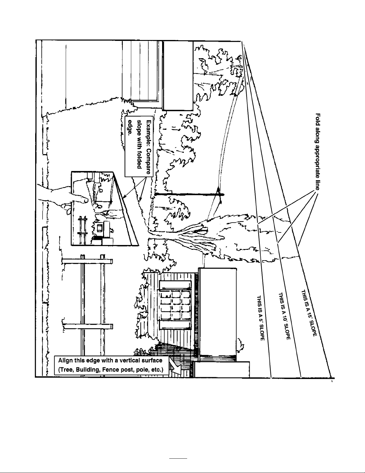
Slope Chart
8
Page 9
Safety and Instructional
Decals
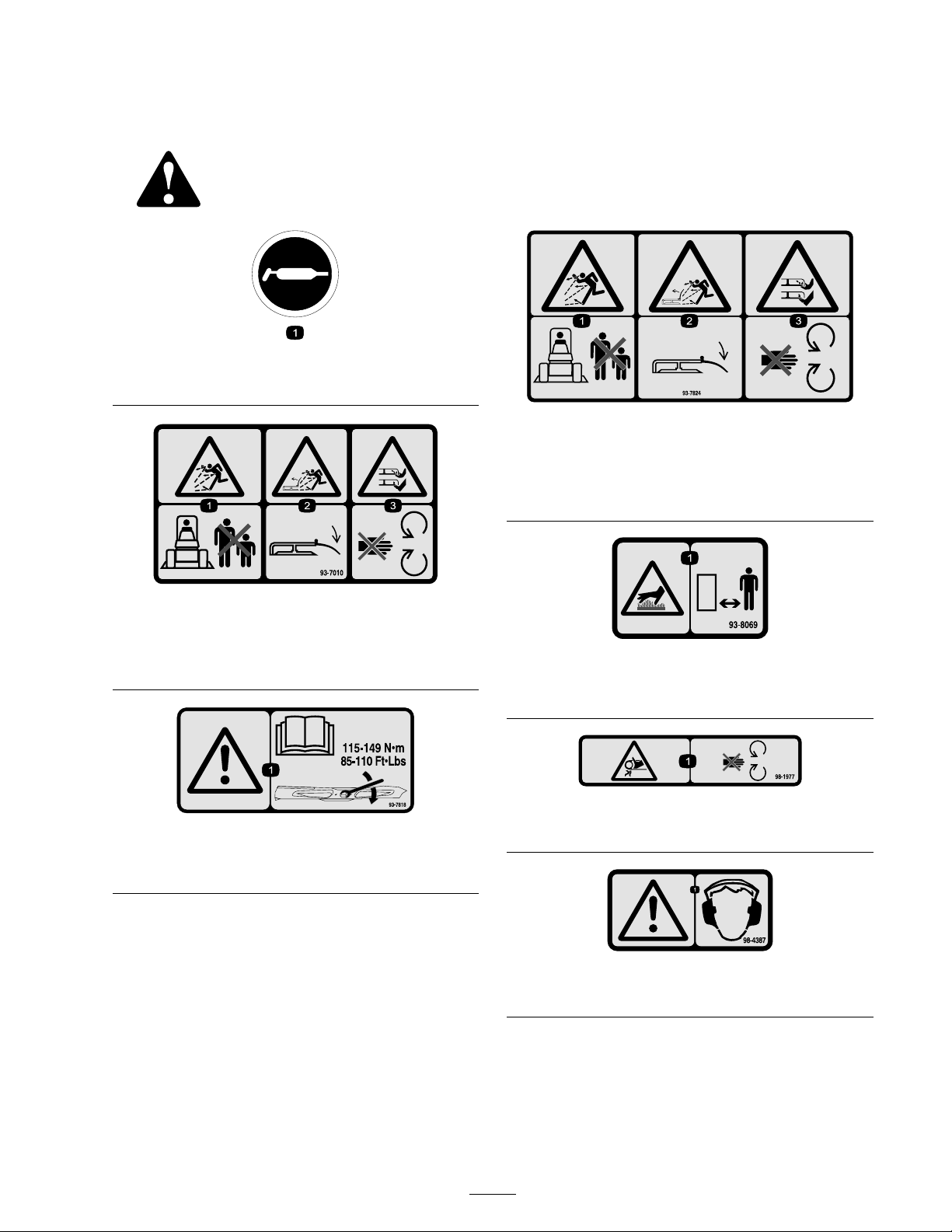
Safety decals and instr uctions are easily visible to the operator and are located near any
area of potential dang er . R e place any decal that is damag ed or lost.
58-6520
1. Grease
93-7824
1. Thrown object hazard—stay a safe distance from the
machine.
2. Thrown object hazard, mower—keep the deector in place.
3. Cutting/dismemberment of hand or foot—stay away from
moving parts.
93-7010
1. Thrown object hazard—
2. Thrown object hazard, mower—keep the deector in place.
3. Cutting/dismemberment of hand or foot—stay away from
moving parts.
93-7818
1. Warning—read the Operator’s Manual for instructions on
torquing the blade bolt/nut to 115-149 N•m (85-110 ft-lb).
93-8069
1. Hot surface/burn hazard—stay a safe distance from the hot
surface.
98-1977
1. Entanglement hazard, belt—stay away from moving parts.
98-4387
1. Warning—wear hearing protection.
9
Page 10
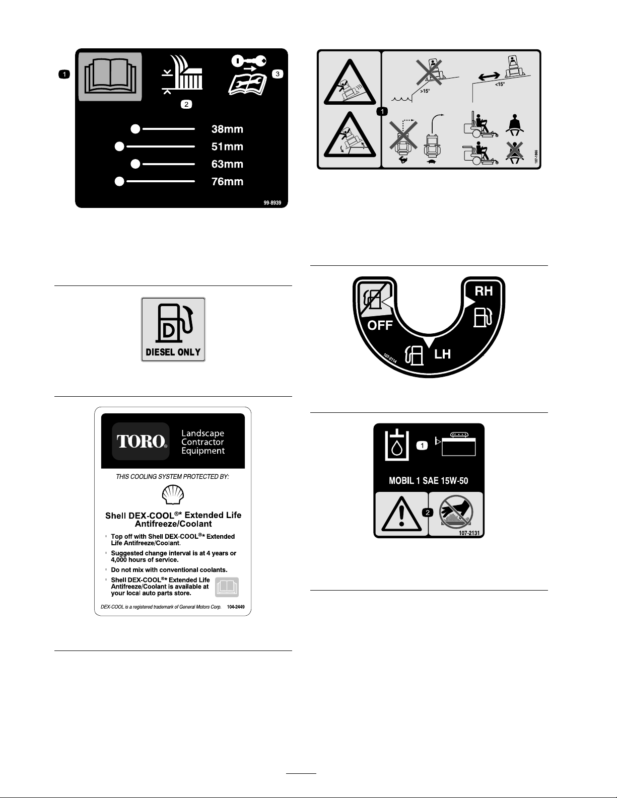
1. Read the Operator’s
Manual .
2. Height of cut
107-1866
1. Sliding and loss of control hazard and tipping hazard,
drop-offs—do not operate the machine near drop-offs,
99-8939
3. Remove the ignition key
and read the instructions
before servicing or
performing maintenance.
slopes greater than 15 degrees, or water; keep a safe
distance from drop-offs; do not turn sharply while traveling
fast, instead, slow down and turn gradually; if the roll bar is
raised, wear the seat belt; if the roll bar is lowered, do not
wear the seat belt.
103-1636
107-2114
107-2131
1. Hydraulic oil level 2. Warning—do not touch the
hot surface.
104-2449
10
Page 11
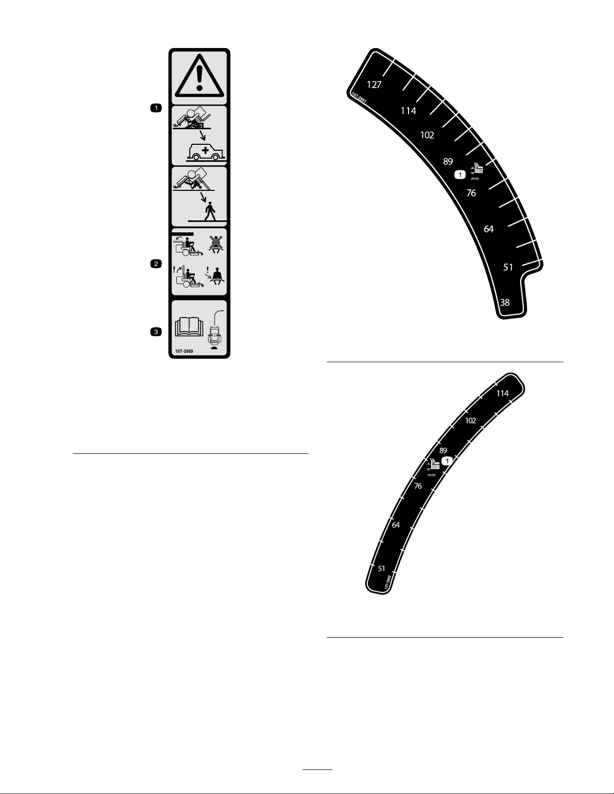
107-3069
1. Warning—there is no rollover protection when the roll bar is
down.
2. To avoid injury or death from a rollover accident, keep the
roll bar in the raised and locked position and wear the seat
belt. Lower the roll bar only when absolutely necessary; do
not wear the seat belt when the roll bar is down.
3. Read the Operator’s Manual ; drive slowly and carefully.
107-3961
1. Height of cut in millimeters
107-3962
1. Height of cut in millimeters
11
Page 12
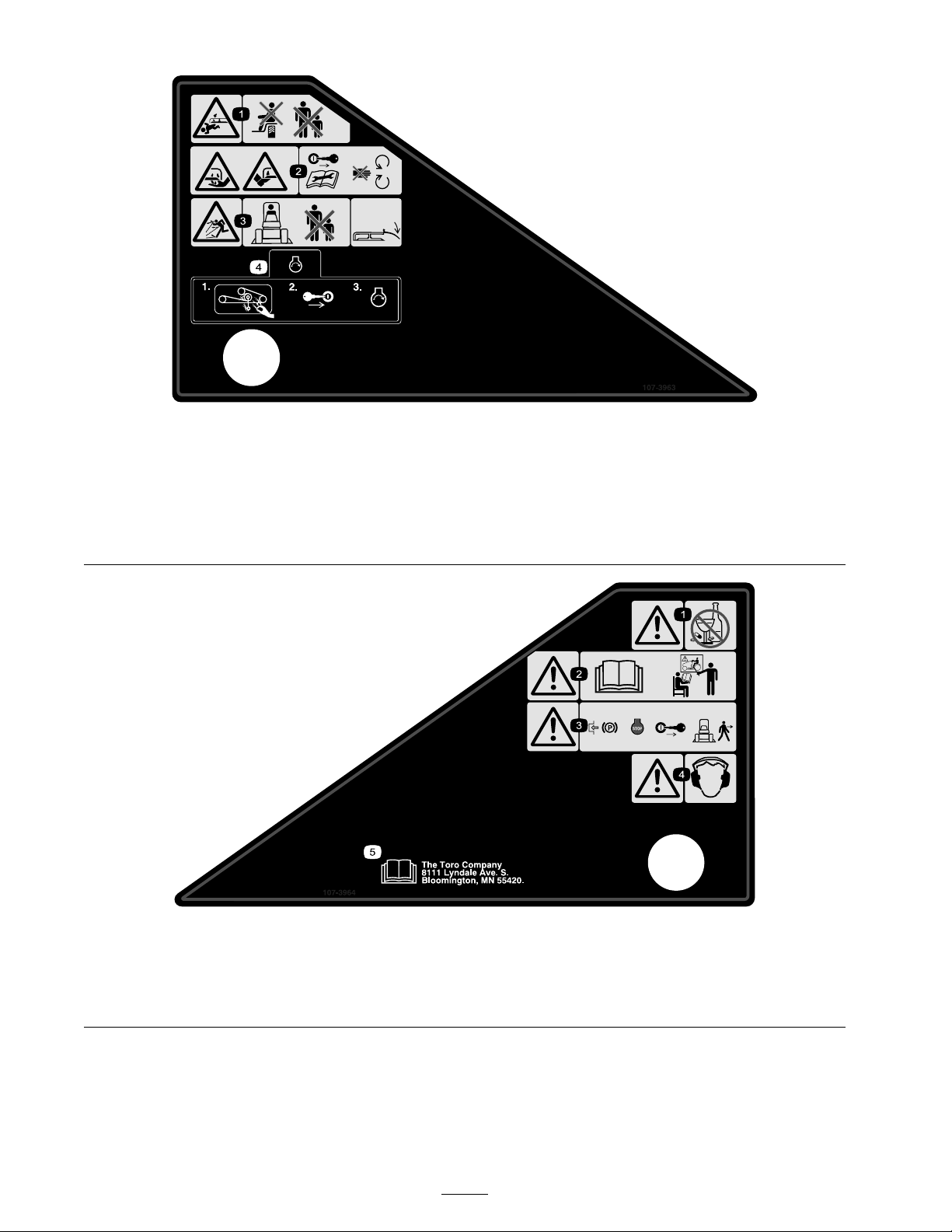
1. Cutting/dismemberment
hazard, mower blade—do
not carry passengers and
keep bystanders away.
2. Cutting/dismemberment
hazard of hand or foot,
mower blade—remove the
ignition key and read the
instructions before servicing
or performing maintenance;
stay away from moving
parts.
107-3963
3. Thrown object hazard—keep
bystanders a safe distance
from the machine and keep
the deector in place.
4. Before starting the engine,
clean grass and debris from
the mower belt and pulleys,
insert the ignition key, and
start the engine.
107-3964
1. Warning—do not use drugs or alcohol. 3. Warning—engage the parking brake,
2. Warning—read the Operator’s Manual
and receive training.
stop the engine, and remove the
ignition key before leaving the machine.
4. Warning—wear hearing protection.
12
5. Read the Operator’s Manual .
Page 13
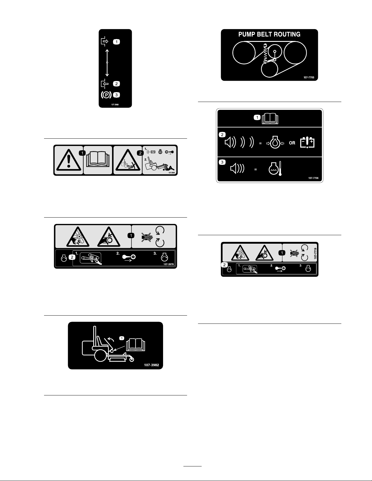
107-3968
1. Disengage
2. Engage
3. Parking brake
107-3969
1. Warning—read the Operator’s Manual .
2. Crushing hazard, mower—engage the parking brake, stop
the engine, and remove the ignition key before working
under the mower.
1. Read the Operator’s
Manual .
2. Pulsing tone indicates low
oil pressure or alternator
not charging.
107-7705
107-7706
3. Continuous tone indicates
that the engine is
overheating.
107-3978
1. Cutting/dismemberment hazard, fan and entanglement
hazard, belt—stay away from moving parts.
2. Before starting the engine, clean grass and debris from the
mower belt and pulleys, insert the ignition key, and start
the engine.
107-3982
1. Operator’s Manual location
107-7719
1. Cutting/dismemberment hazard, fan and entanglement
hazard, belt—stay away from moving parts.
2. Before starting the engine, clean grass and debris from the
mower belt and pulleys, insert the ignition key, and start
the engine.
13
Page 14
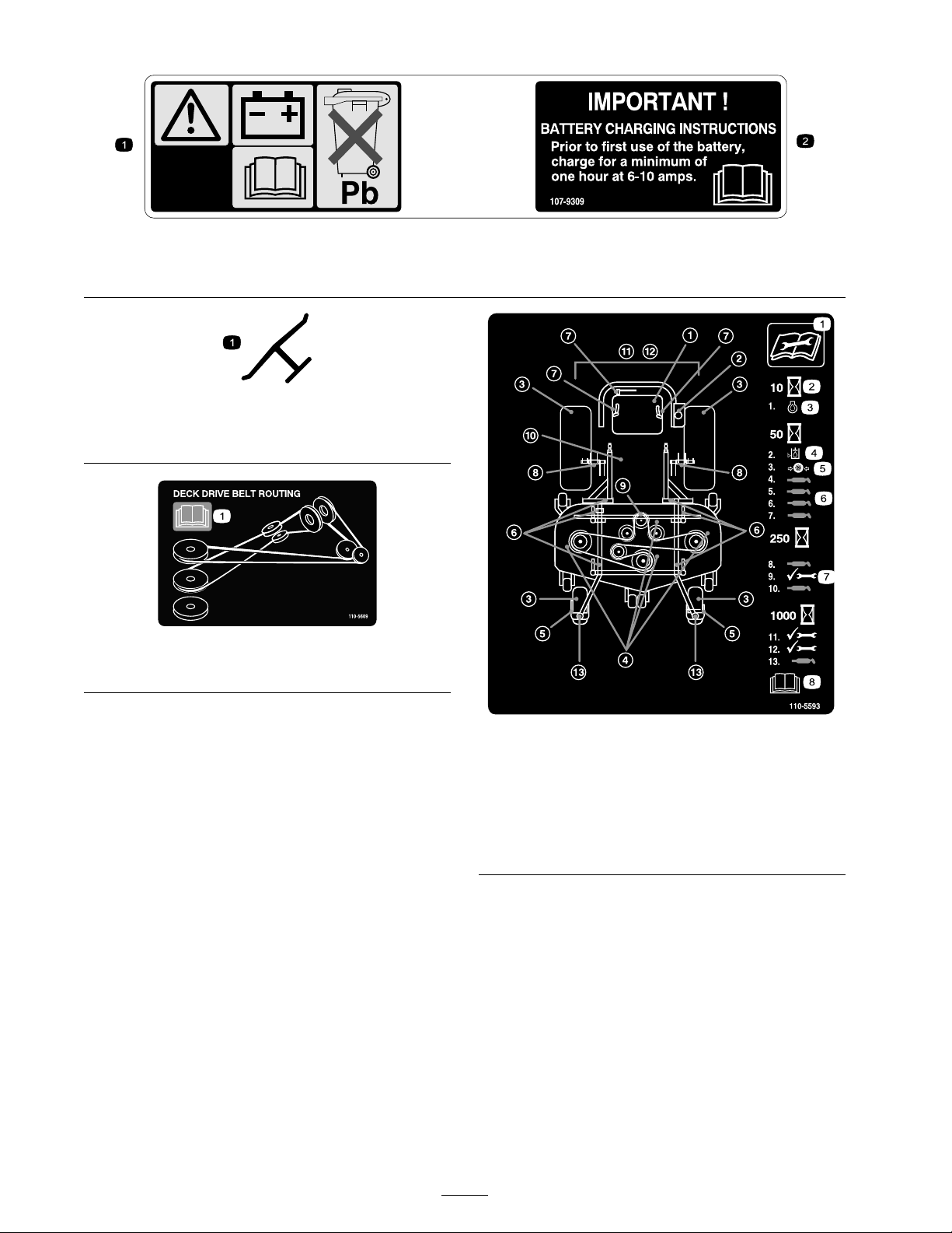
107-9309
1. Warning—read the Operator’s Manual for information on charging the battery; contains lead; do not discard.
2. Read the Operator’s Manual .
Manufacturer’s Mark
1. Indicates the blade is identied as a part from the original
machine manufacturer.
110-5609
1. Read the Operator’s Manual.
110-5593
1. Read the Operator’s
Manual before servicing or
performing maintenance.
2. Maintenance time interval 6. Grease here
3. Engine oil 7. Check and perform any
4. Hydraulic oil level
5. Tire pressure
maintenance necessary.
8. Read the Operator’s Manual
for more information.
14
Page 15
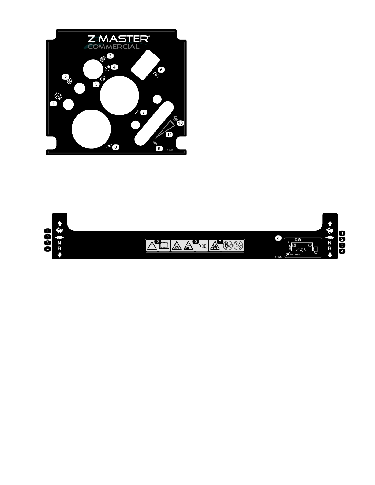
1. Water in fuel warning
2. Engine—preheat
3. Engine—stop
4. Engine—run
5. Engine—start
6. Power take-off (PTO)
1. Fast
2. Slow
110-5724
7. Temperature
8. Power (Volts)
9. Slow
10. Fast
11. Continuous variable setting
107-3967
3. Neutral 5. Warning—read the
4. Reverse
Operator’s Manual .
6. Poison and caustic
liquid/chemical burn
hazard—keep children a
safe distance from the
battery.
7. Explosion hazard—no re,
open ames, or smoking;
avoid sparks.
8. To unlock the traction
drive, turn the by-pass
valve 1 complete revolution
counterclockwise using a
5/8 inch or 16 mm wrench
15
Page 16
Product Overview
Hour Meter
T he hour meter records the n umber of hours the
engine has operated. It operates when the engine
is r unning . Use these times for sc heduling regular
maintenance ( Figure 4 ).
Glow Plug Light (Orange Light)
T he glo w plug indicator light tur ns on when the
ignition switc h is tur ned to the on position. W hen
the light tur ns off , the engine is ready to be star ted
( Figure 4 ).
Water in Fuel Light (Red Light)
T he w ater in fuel light tur ns on when there is w ater
in the fuel. W hen the indicator light tur ns off , the
engine is ready to be star ted ( Figure 4 ).
Temperature Gauge
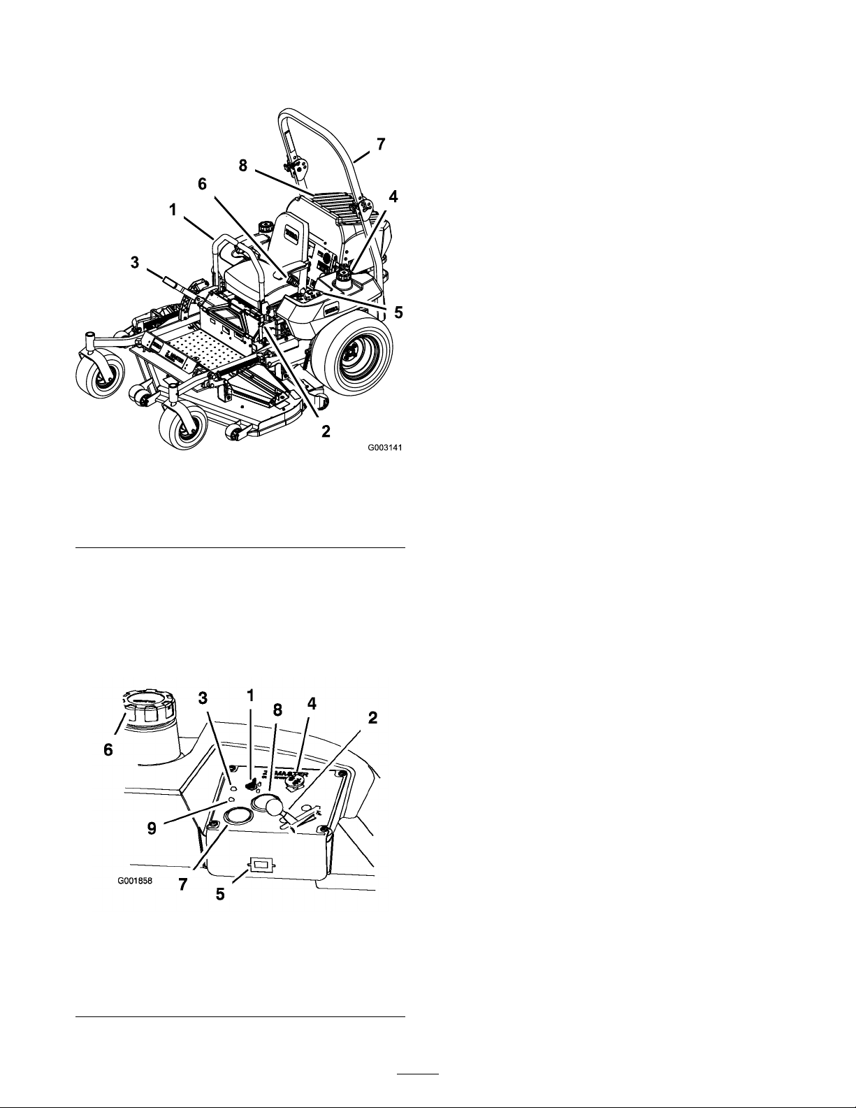
Figure 3
1. Motion control lever 5. Controls
2. Parking brake lever 6. Seat belt
3. Height-of-cut lever 7. Roll bar
4. Fuel cap (both sides)
8. Engine screen
Controls
Become familiar with all the controls before y ou
star t the engine and operate the mac hine ( Figure 3
and Figure 4 ).
T he temperature g aug e registers the temperature
of the coolant in the cooling system ( Figure 4 ).
Audible Alarm
T his mac hine has an audible alar m that aler ts the
user to tur n off the engine or engine damag e can
occur from o v er heating . R efer to Ser vicing the
Cooling System in Cooling System Maintenance ,
pag e 44 .
Volt Meter
T he v olt meter registers the output of the c harging
system ( Figure 4 ).
Figure 4
1. Ignition switch 6. Fuel cap
2. Throttle control 7. Volt meter
3. Glow plug light
4. Power take off (PTO) Switch
5. Hour meter
8. Engine Temperature gauge
9. Water in fuel light
16
Page 17

Operation
Note: Deter mine the left and right sides of the
mac hine from the nor mal operating position.
Adding Fuel
T he engine r uns on clean, fresh diesel fuel with
a minim um octane rating of 40. Purc hase fuel
in quantities that can be used within 30 da ys to
ensure fuel freshness .
Use summer g rade diesel fuel (No . 2-D) at
temperatures abo v e 20° F (-7° C) and winter g rade
diesel fuel (No . 1-D or No . 1-D/2-D blend) belo w
20° F (-7° C). Use of winter g rade diesel fuel at
lo w er temperatures pro vides lo w er flash point
and pour point c haracteristics , therefore easing
star tability and lessening c hances of c hemical
se paration of the fuel due to lo w er temperatures
(w ax appearance , whic h ma y plug filters).
Use of summer g rade diesel fuel abo v e 20° F (-7°
C) will contribute to w ard long er life of the pump
components .
Important: Do not use k er osene or gasoline
instead of diesel fuel. F ailur e to obser v e this
caution will dama ge the engine.
In cer tain conditions, fuel is extr emel y
flamma ble and highl y explosi v e. A fir e or
explosion fr om fuel can bur n y ou and other s
and can dama ge pr oper ty .
• Fill the fuel tank outdoor s, in an open
ar ea, when the engine is cold. W ipe up
an y fuel that spills.
• Nev er fill the fuel tank inside an enclosed
trailer .
• Do not fill the fuel tank completel y full.
Add fuel to the fuel tank until the lev el is
1/4 to 1/2 inch (6 to 13 mm) belo w the
bottom of the filler neck. T his empty
space in the tank allo ws fuel to expand.
• Nev er smok e when handling fuel, and
stay a w ay fr om an open flame or wher e
fuel fumes may be ignited by a spar k.
• Stor e fuel in an appr o v ed container and
k eep it out of the r each of childr en.
Nev er buy mor e than a 30-day suppl y of
fuel.
• Al w ays place fuel container s on the
g r ound a w ay fr om y our v ehicle bef or e
filling .
Fuel is har mful or f atal if s w allo w ed.
Long-ter m exposur e to v apor s can cause
serious injur y and illness.
• A v oid pr olonged br eathing of v apor s.
• K eep f ace a w ay fr om nozzle and gas tank
or conditioner opening .
• K eep gas a w ay fr om ey es and skin.
• Do not fill fuel container s inside a v ehicle
or on a tr uck or trailer bed because
interior car pets or plastic tr uck bed liner s
may insulate the container and slo w the
loss of an y static charge.
• W hen practical, r emo v e gas-po w er ed
equipment fr om the tr uck or trailer and
r efuel the equipment with its wheels on
the g r ound.
• If this is not possible, then r efuel such
equipment on a tr uck or trailer fr om a
por ta ble container , rather than fr om a
fuel dispenser nozzle.
• If a fuel dispenser nozzle must be used,
k eep the nozzle in contact with the rim
of the fuel tank or container opening at
all times until fueling is complete.
Filling the Fuel Tank
1. Shut the engine off and set the parking brak e .
17
Page 18
2. Clean around eac h fuel tank cap and remo v e
the cap . Add fuel to both fuel tanks , until the
lev el is 1/4 to 1/2 inc h (6 to 13 mm) belo w
the bottom of the filler nec k. T his space in the
tank allo ws the fuel to expand. Do not fill the
fuel tanks completely full.
3. Install fuel tank caps securely . Wipe up any
fuel that ma y ha v e spilled.
4. If possible , fill the fuel tank after eac h use . T his
will minimize possible buildup of condensation
inside the fuel tank.
Checking the Engine Oil
Level
Before y ou star t the engine and use the mac hine ,
c hec k the oil lev el in the engine crankcase; refer
to Chec king Oil Lev el in Engine Maintenance ,
pag e 35
Switching the Fuel Tanks
Important: Do not r un the machine out of
fuel.
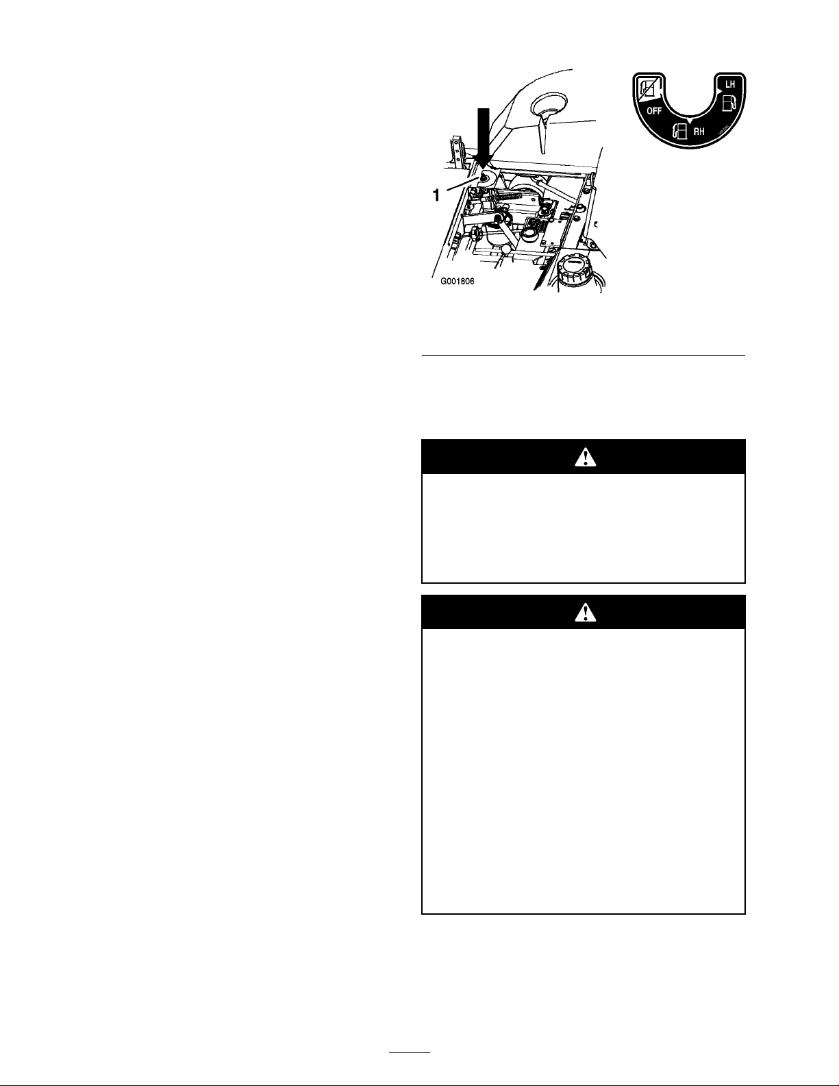
T he fuel selector v alv e is located behind the left
side of the seat.
T he unit has tw o fuel tanks . One tank is on the left
side and one on the right side . Eac h tank connects
to the fuel selector v alv e . F rom there a common
fuel line leads to the engine ( Figure 5 ).
T o use the left side fuel tank rotate the fuel selector
v alv e to the LH, left-hand, location. T o use the
right side fuel tank rotate the fuel selector v alv e to
the RH, right-hand, location ( Figure 5 )
Close the fuel selector v alv e before transpor ting
or storing mac hine .
Figure 5
1. Left side fuel tank 2. Fuel selector valve
Using the Rollover
Protection System (ROPS)
T o a v oid injur y or death fr om r ollo v er : k eep
the r oll bar in the raised lock ed position and
use the seat belt.
Ensur e that the r ear par t of the seat is
secur ed with the seat latch.
T her e is no r ollo v er pr otection when the r oll
bar is in the do wn position.
• Lo w er the r oll bar onl y when a bsolutel y
necessar y .
• Do not w ear the seat belt when the r oll
bar is in the do wn position.
• Dri v e slo wl y and car efull y .
• R aise the r oll bar as soon as clearance
per mits.
• Check car efull y f or o v erhead clearances
(i.e. branches, doorw ays, electrical wir es)
bef or e dri ving under an y objects and do
not contact them.
Important: Lo w er the r oll bar onl y when
a bsolutel y necessar y .
1. T o lo w er the roll bar , remo v e the hair pin cotter
pins and remo v e the tw o pins ( Figure 7 ).
18
Page 19
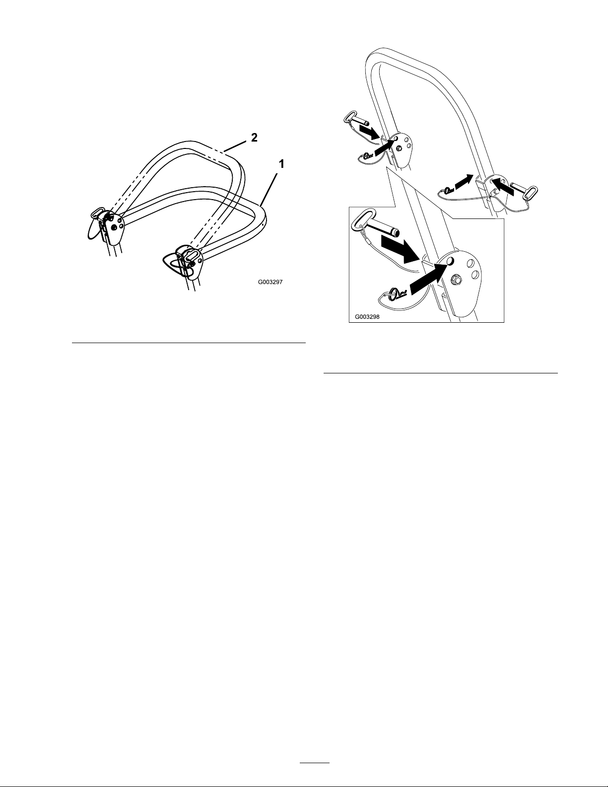
2. Lo w er the roll bar to the do wn position. T here
are tw o do wn positions . See Figure 6 for the
positions .
3. Install the tw o pins and secure them with the
hair pin cotter pins ( Figure 7 ).
Figure 6
1. Full down position 2. Down position with bagger
installed
Important: Ensur e that the r ear par t of
the seat is secur ed with the seat latch.
1. Roll bar
2. Raised position
Figure 7
3. Pin
4. Hairpin cotter pin
4. T o raise the roll bar , remo v e the hair pin cotter
pins and remo v e the tw o pins ( Figure 7 ).
5. Raise the roll bar to the upright position and
install the tw o pins and secure them with the
hair pin cotter pins ( Figure 7 ).
Important: Al w ays use the seat belt with
the r oll bar in the raised position.
Think Safety First
Please read all safety instr uctions and symbols
in the safety section. Kno wing this infor mation
could help y ou or b ystanders a v oid injur y .
19
Page 20
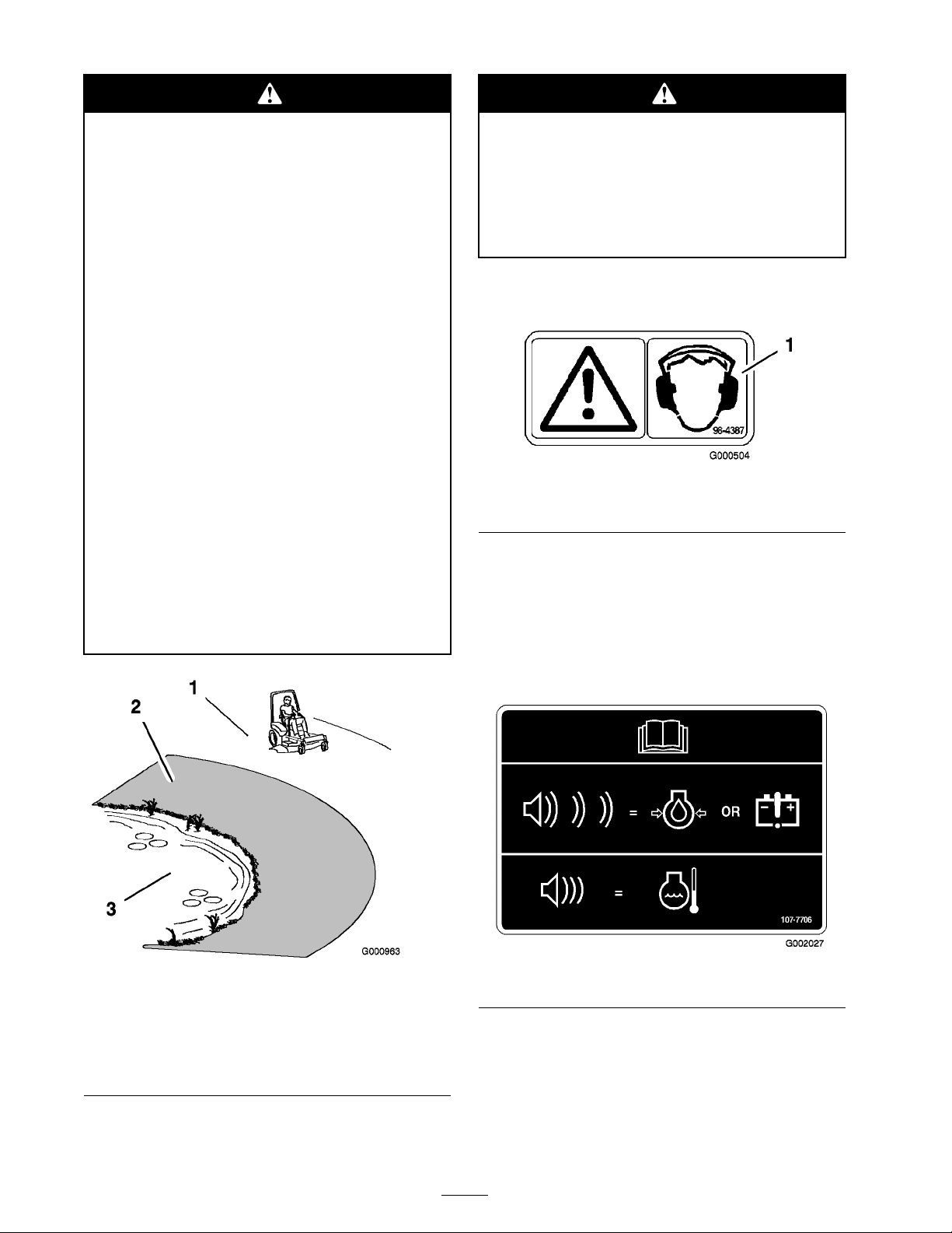
Operating on w et g rass or steep slopes can
cause sliding and loss of contr ol.
W heels dr opping o v er edges can cause
r ollo v er s, which may r esult in serious injur y ,
death or dr o wning .
T her e is no r ollo v er pr otection when the r oll
bar is do wn.
Al w ays k eep the r oll bar in the raised and
lock ed position and use the seat belt.
R ead and f ollo w the r ollo v er pr otection
instr uctions and w ar nings.
T o a v oid loss of contr ol and possibility of
r ollo v er :
T his machine pr oduces sound lev els in
ex cess of 85 dB A at the operator s ear and
can cause hearing loss thr ough extended
periods of exposur e.
W ear hearing pr otection when operating
this machine.
T he use of protecti v e equipment for eyes , ears ,
feet and head is recommended.
• Do not operate near dr op-of fs or near
w ater .
• Do not operate on slopes g r eater than
15 deg r ees.
• R educe speed and use extr eme caution
on slopes.
• A v oid sudden tur ns or rapid speed
changes.
Figure 9
1. Warning— wear hearing protection
Understanding the Audible
Alarms
T his mac hine has an audible alar m that aler ts the
user to tur n off the engine or engine damag e can
occur .
1. Safe Zone-use the Z Master
here on slopes less than
15 degrees or at areas.
2. Use walk behind mower
and/or hand trimmer near
drop-offs and water.
Figure 8
Figure 10
3. Water
Continuous Audible Alarm
T he contin uous audible alar m aler ts the user that
the engine is o v er heating . R efer to Ser vicing the
Cooling System.
20
Page 21
Pulsing Audible Alarm
T he pulsing audible alar m aler ts the user to lo w oil
pressure or the alter nator is not c harging . R efer to
Chec king the Engine Oil and c hec k the alter nator
belt.
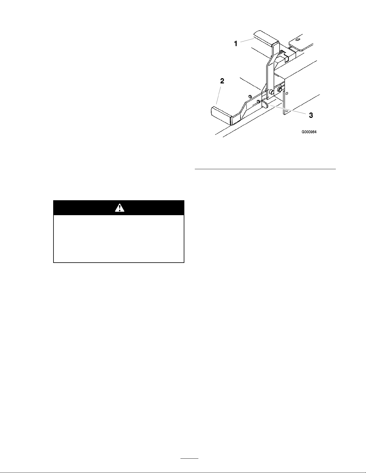
Operating the Parking
Brake
Alw a ys set the parking brak e when y ou stop the
mac hine or lea v e it unattended.
Setting the Parking Brake
1. Mo v e the motion control lev ers ( Figure 16 ) out
to the neutral loc k position.
2. Pull up and bac k on the parking brak e lev er to
set the parking brak e ( Figure 11 ). T he parking
brak e lev er should sta y fir mly in the eng ag ed
position.
P ar king brak e may not hold machine
par k ed on a slope and could cause
per sonal injur y or pr oper ty dama ge.
Do not par k on slopes unless wheels ar e
chock ed or block ed
Releasing the Parking Brake
Push forw ard and do wn on the parking brak e
lev er to release the parking brak e ( Figure 11 ). T he
parking brak e is diseng ag ed and the lev er will rest
ag ainst the brak e stop .
Figure 11
1. Parking brake-ON 3. Brake Stop
2. Parking brake-OFF
Starting and Stopping the
Engine
Starting the Engine in Normal
Weather
1. Raise the R OPS up and loc k into place , sit on
the seat and fasten the seat belt.
2. Mo v e the motion controls to the neutral loc k ed
position.
3. Set the parking brak e; refer to Setting the
P arking Brak e .
4. Mo v e the PTO (po w er tak e off) switc h to the
off position ( Figure 12 ).
5. Mo v e the throttle lev er to the middle position
( Figure 12 ).
6. T ur n the ignition k ey cloc kwise to the r un
position ( Figure 12 ). T he glo w plug light will
tur n on.
7. After the glo w plug indicator light g oes out,
tur n the k ey to the star t position. when the
engines star ts release the k ey .
21
Page 22
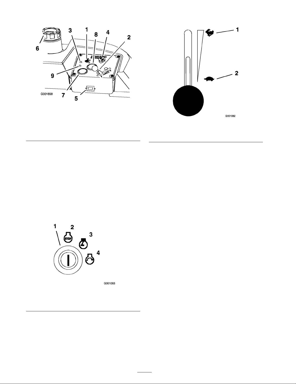
Figure 12
1. Ignition switch 6. Fuel cap
2. Throttle control 7. Volt meter
3. Glow plug light
4. Power take off (PTO) Switch
5. Hour meter
8. Engine Temperature gauge
9. Water in fuel light
Important: Use star ting cy cles of no
mor e than 30 seconds per min ute to a v oid
o v erheating the star ter motor .
Figure 14
1. Throttle—fast 2. Throttle—slow
Starting the Engine in Cold Weather
(Below 14°F or -10°C)
8. If the engine does not star t immediately , mo v e
the throttle control to fast and tur n the k ey to
the star t position.
Note: Additional star ting cycles ma y be
required when star ting the engine for the first
time after the fuel system has been completely
without fuel.
Figure 13
1. Ignition switch
2. Off
3. Run
4. Start
Use the cor rect engine oil for the star ting
temperature . R efer to Ser vicing the Engine Oil in
Engine Maintenance , pag e 35 .
1. Star t the engine with the throttle in the F ast
position.
2. T ur n the ignition k ey cloc kwise to the r un
position ( Figure 13 ). T he glo w plug light will
tur n on.
3. After the glo w plug indicator light g oes out,
tur n the k ey to the star t position. when the
engines star ts release the k ey .
Important: Use star ting cy cles of no
mor e than 30 seconds per min ute to a v oid
o v erheating the star ter motor .
Stopping the Engine
1. Diseng ag e the PTO , mo v e the motion control
lev ers to the neutral loc k ed position and set
the parking brak e ( Figure 15 ).
2. Mo v e the throttle lev er midw a y betw een the
slo w and fast positions ( Figure 14 ).
3. Let the engine idle for 60 seconds .
4. T ur n the ignition k ey to the off position
( Figure 13 ). W ait for all mo ving par ts to stop
before lea ving the operating position.
22
Page 23
5. R emo v e the k ey to prev ent possibility of
someone accidentally star ting the mac hine
before transpor ting or storing mac hine .
6. Close the fuel selector v alv e before transpor ting
or storing the mac hine .
Important: Mak e sur e that the fuel
selector v alv e is closed bef or e transpor ting
or storing the machine, as fuel leaka ge
may occur . Set the par king brak e bef or e
transpor ting .
Important: Mak e sur e to r emo v e the k ey
as the fuel pump may r un and cause the
batter y to lose charge.
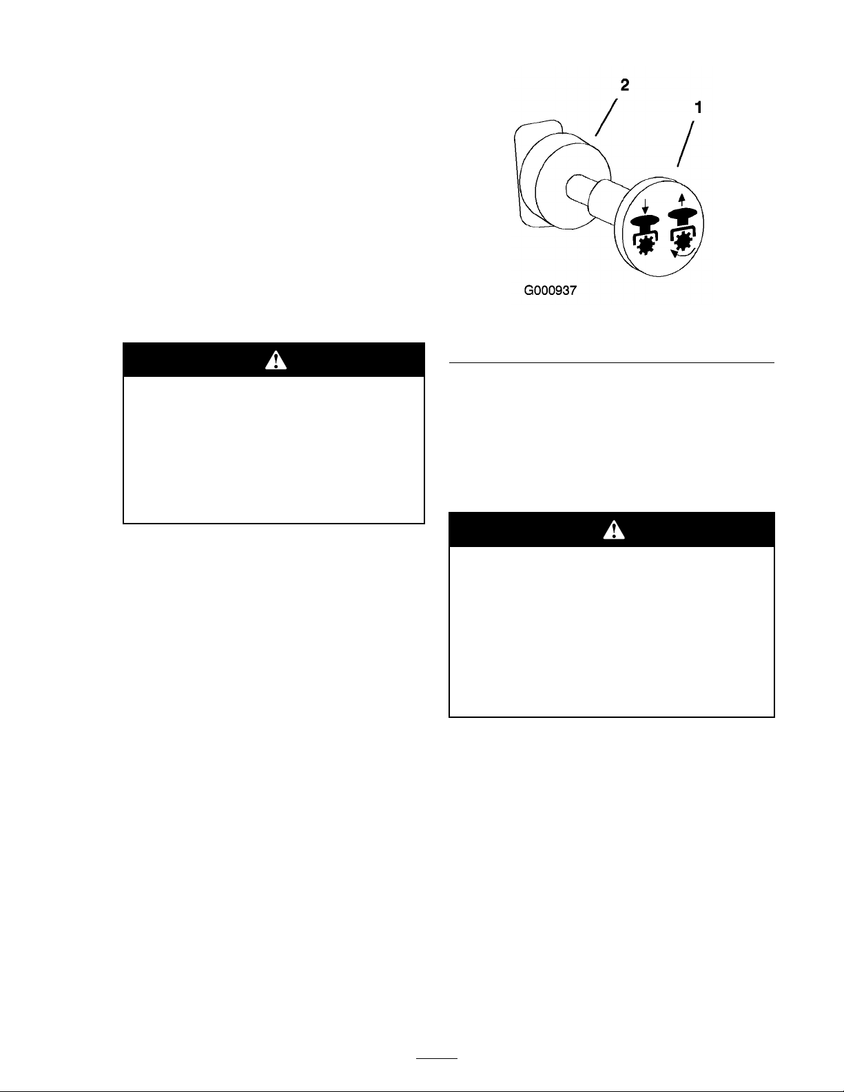
Figure 15
1. PTO-On
2. PTO-Off
Childr en or bystander s may be injur ed
if they mo v e or attempt to operate the
tractor while it is unattended.
Al w ays r emo v e the ignition k ey and
set the par king brak e when lea ving the
machine unattended, ev en if just f or a
few min utes.
Operating the Power Take
Off (PTO)
T he po w er tak e off (PTO) switc h star ts and stops
the mo w er blades and any po w ered attac hments .
Engaging the PTO
1. If the engine is cold, allo w the engine to w ar m
up 5 to 10 min utes before eng aging the PTO .
2. W hile seated in the seat, release the pressure on
the traction control lev ers and place in neutral.
Disengaging the PTO
T o diseng ag e , push the PTO switc h to the of f
position ( Figure 15 ).
The Safety Interlock System
If safety inter lock s witches ar e disconnected
or dama ged the machine could operate
unexpectedl y causing per sonal injur y .
• Do not tamper with the inter lock
s witches.
• Check the operation of the inter lock
s witches dail y and r eplace an y dama ged
s witches bef or e operating the machine.
Understanding the Safety Interlock
System
3. Place the throttle in the fast position.
Note: Eng aging the PTO with the throttle
at the half or less position will cause ex cessi v e
w ear to the dri v e belts .
4. Pull out on the po w er tak e off (PTO) switc h to
eng ag e it ( Figure 15 ).
T he safety interloc k system is designed to prev ent
the engine from star ting unless:
• Y ou are sitting on the seat.
• T he parking brak e is eng ag ed.
• T he po w er tak e off (PTO) is diseng ag ed.
• T he motion control lev ers are in the neutral
loc k ed position
T he safety interloc k system also is designed to stop
the engine when the traction controls are mo v ed
from the loc k ed position with the parking brak e
23
Page 24
eng ag ed or if y ou rise from the seat when the PTO
is eng ag ed.
Testing the Safety Interlock System
T est the safety interloc k system before y ou use
the mac hine eac h time . If the safety system
does not operate as described belo w , ha v e an
A uthorized Ser vice Dealer re pair the safety system
immediately .
Machine can spin v er y rapidl y . Operator
may lose contr ol of machine and cause
per sonal injur y or dama ge to machine.
• Use caution when making tur ns.
• Slo w the machine do wn bef or e making
shar p tur ns.
1. Sitting on the seat, eng ag e the parking brak e
and mo v e the PTO to on. T r y star ting the
engine; the engine should not crank.
2. Sitting on the seat, eng ag e the parking brak e
and mo v e the PTO to off . Mo v e either motion
control lev er (out of neutral loc k ed position).
T r y star ting the engine; the engine should not
crank. R e peat for other control lev er .
3. Sitting on the seat, eng ag e the parking brak e ,
mo v e the PTO switc h to off and mo v e the
motion control lev ers to neutral loc k position.
No w star t the engine . W hile the engine is
r unning, release the parking brak e , eng ag e the
PTO and rise slightly from the seat; the engine
should stop .
4. Sitting on the seat, eng ag e the parking brak e ,
mo v e the PTO switc h to off and mo v e the
motion control lev ers to neutral loc k position.
No w star t the engine . W hile the engine is
r unning, center either motion control and
mo v e (forw ard or rev erse); the engine should
stop . R e peat for other motion control.
5. Sitting on the seat, diseng ag e the parking brak e ,
mo v e the PTO switc h to off and mo v e the
motion control lev ers to neutral loc k position.
T r y star ting the engine; the engine should not
crank.
Driving Forward
1. R elease the parking brak e; refer to R eleasing
the P arking Brak e in Operation , pag e 17 .
2. Mo v e the lev ers to the center , un-loc k ed
position.
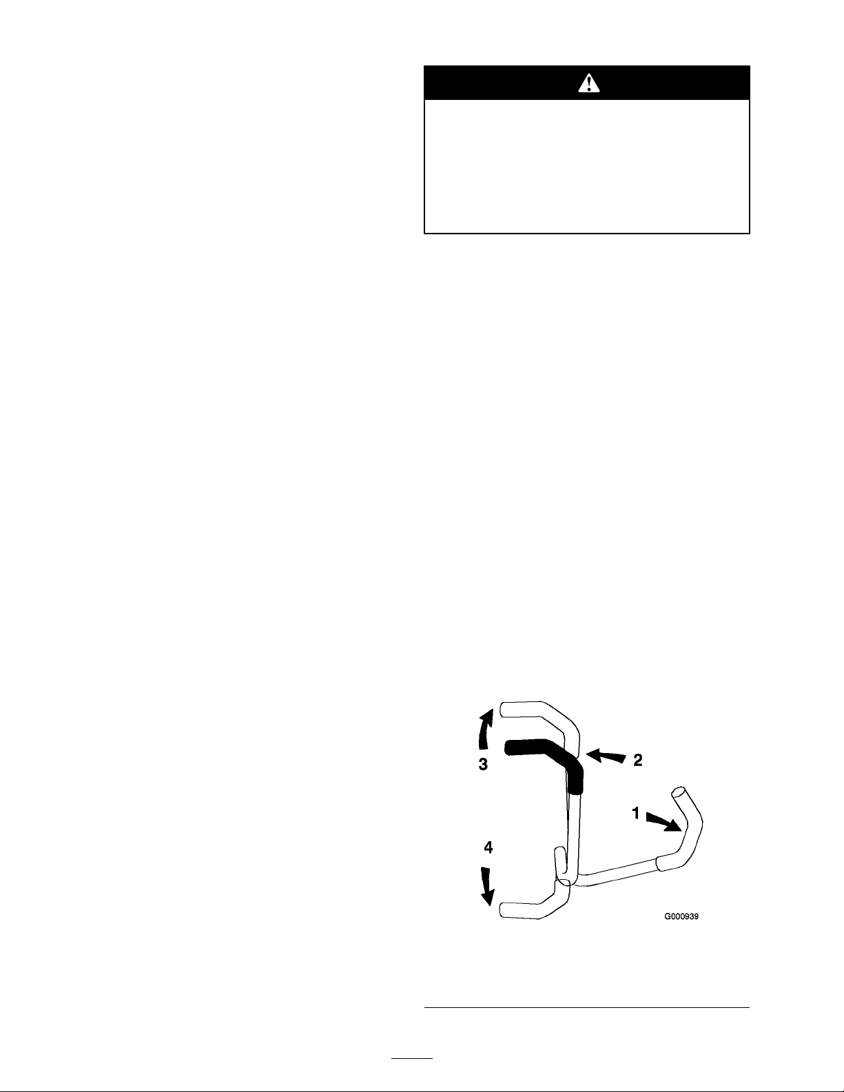
3. T o g o forw ard, slo wly push the motion control
lev ers forw ard ( Figure 16 ).
Note: T he engine will kill if the traction
control lev ers are mo v ed with the parking
brak e eng ag ed.
T o g o straight, apply equal pressure to both
motion control lev ers ( Figure 16 ).
T o tur n, mo v e the motion control lev er to w ard
neutral in the direction y ou w ant to tur n
( Figure 16 ).
T he far ther y ou mo v e the traction control
lev ers in either direction, the faster the mac hine
will mo v e in that direction.
T o stop , pull the motion control lev ers to the
neutral position.
Driving Forward or
Backward
T he throttle control regulates the engine speed as
measured in r pm (rev olutions per min ute). Place
the throttle control in the fast position for best
perfor mance . Alw a ys operate in the full throttle
position when mo wing .
1. Motion control
lever-neutral lock position
2. Center un-lock position 4. Backward
24
Figure 16
3. Forward
Page 25
Driving Backward
1. Mo v e the lev ers to the center , un-loc k ed
position.
2. T o g o bac kw ard, slo wly pull the motion control
lev ers rearw ard ( Figure 16 ).
T o g o straight, apply equal pressure to both
motion control lev ers ( Figure 16 ).
T o tur n, release pressure on the motion control
lev er to w ard the direction y ou w ant to tur n
( Figure 16 ).
T o stop , push the motion control lev ers to the
neutral position.
Stopping the Machine
T o stop the mac hine , mo v e the traction control
lev ers to neutral and mo v e to loc k ed position,
diseng ag e the po w er tak e off (PTO), and tur n the
ignition k ey to off .
Set the parking brak e when y ou lea v e the mac hine;
refer to Setting the P arking Brak e in Operation ,
pag e 17 . R emember to remo v e the k ey from the
ignition switc h.
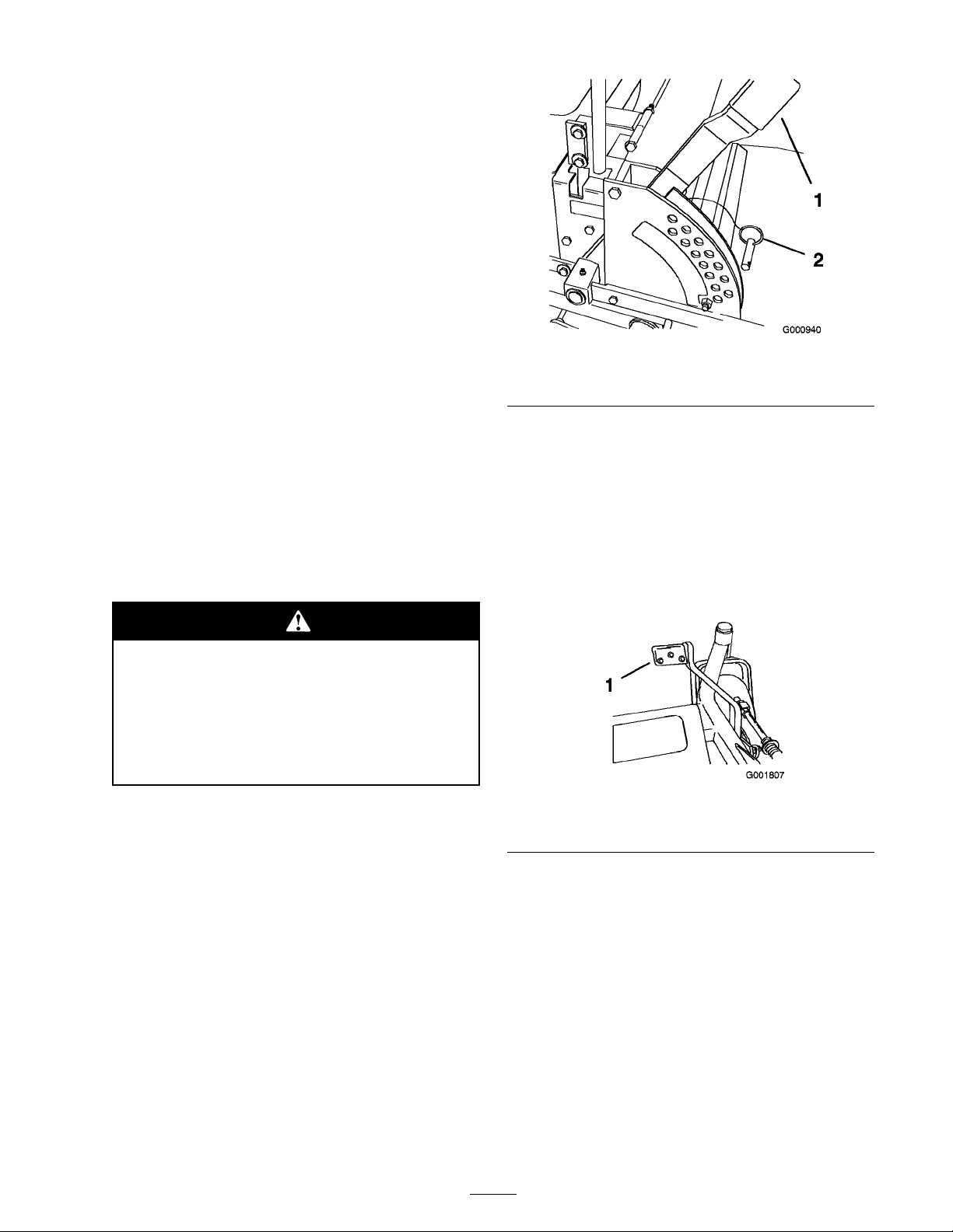
Figure 17
1. Height of cut lever 2. Clevis Pin
Using the Lift Assist Lever
T he lift assist lev er is used along with the
height-of-cut lev er for raising the mo w er . T his
allo ws for easier raising of the mo w er .
1. Place y our foot onto lift assist lev er .
2. Press on the lift assist lev er while pulling up on
the height-of-cut lev er ( Figure 18 ).
Childr en or bystander s may be injur ed if
they mo v e or attempt to operate the tractor
while it is unattended.
Al w ays r emo v e the ignition k ey and set the
par king brak e when lea ving the machine
unattended, ev en if just f or a few min utes.
Adjusting the Height-of-Cut
T he height-of-cut is adjusted from 1-1/2 to 5 inc h
(38 to 127 mm) in 1/4 inc h (6 mm) increments
b y relocating the clevis pin into different hole
locations .
1. Raise the height-of-cut lev er to the transpor t
position (also the 5 inc h (127 mm) cutting
height position) ( Figure 17 ).
2. T o adjust, remo v e the clevis pin from the
height-of-cut brac k et ( Figure 17 ).
3. Select a hole in the height-of-cut brac k et
cor responding to the height-of-cut desired
and, inser t the clevis pin ( Figure 17 ).
4. Mo v e the lev er to the selected height.
Figure 18
1. Lift Assist Lever
Adjusting the Anti-Scalp
Rollers
W henev er y ou c hang e the height-of-cut, it is
recommended to adjust the height of the anti-scalp
rollers .
1. Diseng ag e the PTO , mo v e the motion control
lev ers to the neutral loc k ed position and set
the parking brak e .
2. Stop the engine , remo v e the k ey , and w ait for
all mo ving par ts to stop before lea ving the
operating position.
25
Page 26
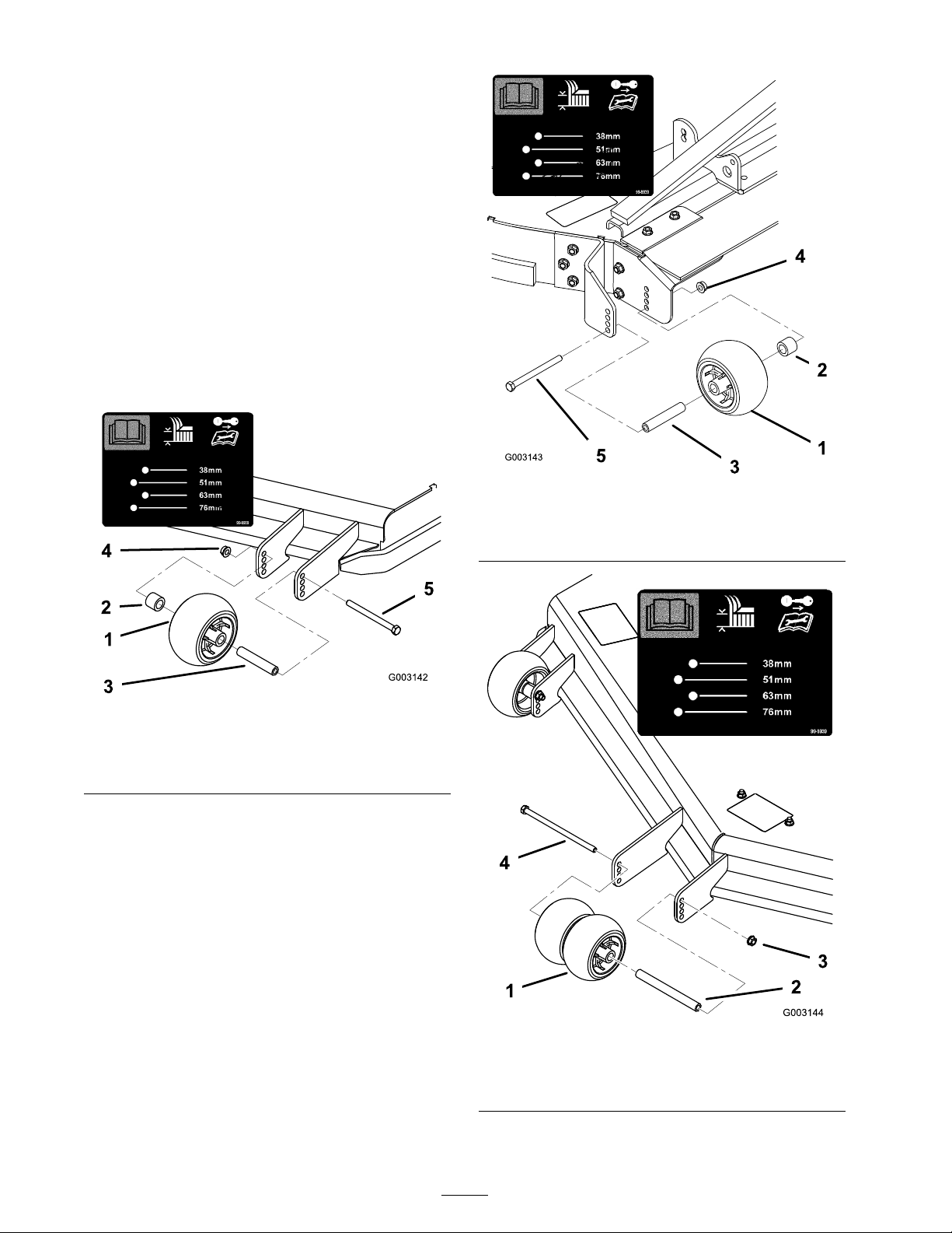
3. After adjusting the height-of-cut, adjust the
rollers b y remo ving the flang e n ut, bushing,
spacer , and bolt ( Figure 19 , Figure 20 and
Figure 21 ).
Note: T he tw o middle rollers will not ha v e a
spacer ( Figure 20 ).
4. Select a hole so the anti-scalp roller is
positioned to the nearest cor responding
height-of-cut desired.
5. Install the flang e n ut bushing, spacer , and bolt.
T or que to 40-45 ft-lb (54-61 N•m) ( Figure 19 ,
Figure 20 and Figure 21 ).
6. R e peat this adjustment on the other anti-scalp
rollers .
Figure 20
1. Anti-scalp roller 3. Flange Nut
2. Bushing 4. Bolt
Figure 19
1. Anti-scalp roller 4. Flange Nut
2. Spacer
3. Bushing
5. Bolt
Figure 21
1. Anti-scalp roller 4. Flange Nut
2. Spacer
3. Bushing
5. Bolt
26
Page 27
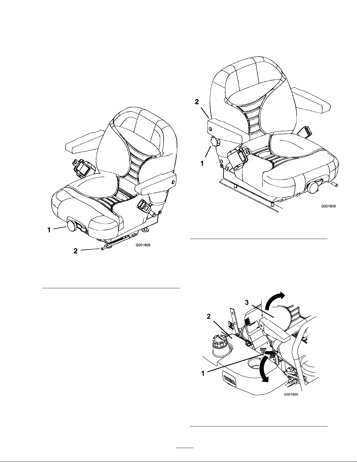
Positioning the Seat
Changing the Seat Position
T he seat can mo v e forw ard and bac kw ard.
P osition the seat where y ou ha v e the best control
of the mac hine and are most comfor table .
1. T o adjust, mo v e the lev er sidew a ys to unloc k
seat ( Figure 22 ).
T o adjust it, tur n the knob , under the right-side
ar m rest, in either direction to pro vide the best
comfor t ( Figure 23 ).
Figure 22
1. Seat suspension knob 2. Seat position adjustment
lever
2. Slide the seat to the desired position and
release lev er to loc k in position.
Changing the Seat Suspension
T he seat can be adjusted to pro vide a smooth and
comfor table ride . P osition the seat where y ou are
most comfor table .
T o adjust it, tur n the knob in front either direction
to pro vide the best comfor t ( Figure 22 ).
Changing the Back Position
Figure 23
1. Back rest knob 2. Right-side arm rest
Unlatching the Seat
Push the seat latc h rearw ard to unlatc h the seat.
T his will allo w access to the mac hine under the
seat ( Figure 24 ).
T he bac k of the seat can be adjusted to pro vide
a comfor table ride . P osition the bac k of the seat
where it is most comfor table .
Figure 24
1. Seat latch
2. Fuel cap
27
3. Seat
Page 28
Pushing the Machine by
Hand
Important: Al w ays push the machine
by hand. Nev er to w the machine because
h y draulic dama ge may occur .
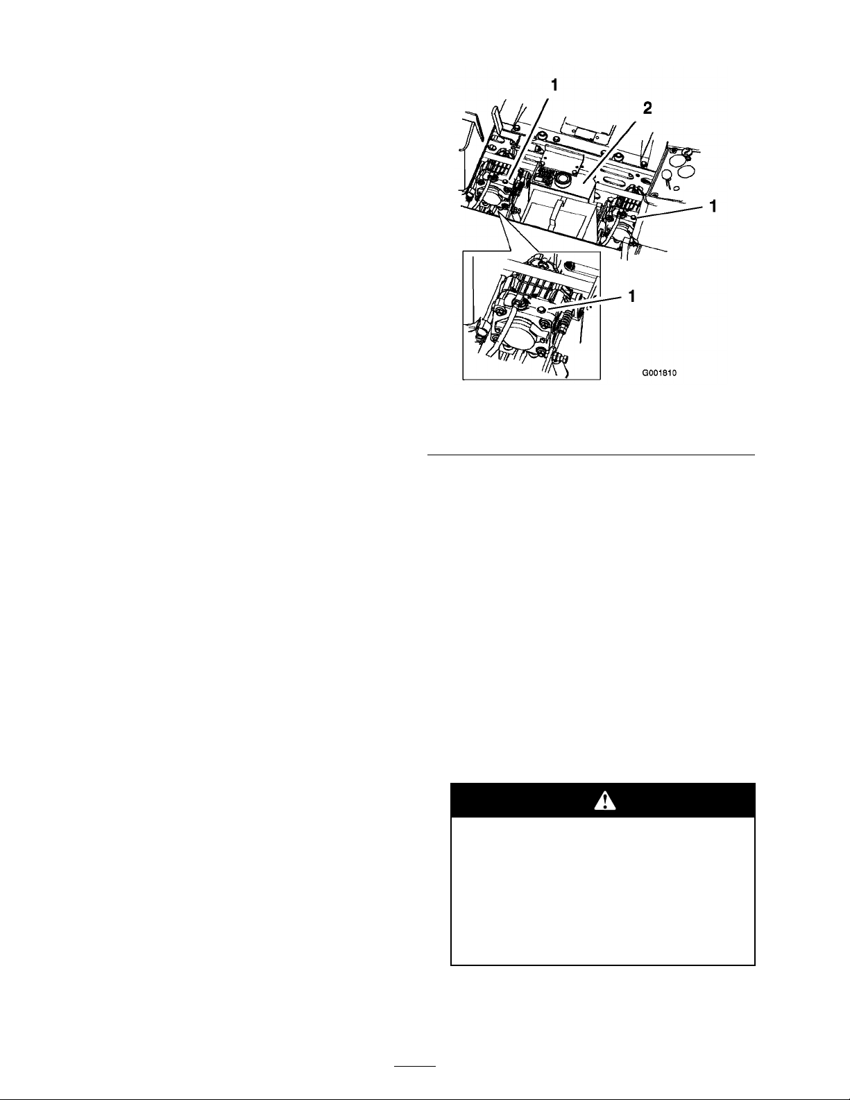
Pushing the Machine
1. Diseng ag e the po w er tak e off (PTO) and
tur n the ignition k ey to off . Mo v e the lev ers
to neutral loc k ed position and apply parking
brak e . R emo v e the k ey .
2. R otate the b y-pass v alv es countercloc kwise
1 tur n to push. T his allo ws h y draulic fluid to
b y-pass the pump enabling the wheels to tur n
( Figure 25 ).
Important: Do not r otate by-pass v alv es
mor e than 1 tur n. T his pr ev ents v alv es
fr om coming out of the body and causing
fluid to r un out.
Figure 25
1. Side console controls 3. Hydraulic pumps
2. By-pass valve
3. Diseng ag e parking brak e before pushing .
Changing to Machine Operation
R otate the b y-pass v alv es cloc kwise 1 tur n to
operate mac hine ( Figure 25 ).
Note: Do not o v er tighten the b y-pass v alv es .
T he mac hine will not dri v e unless b y-pass v alv es
are tur ned in.
Transporting Machines
Use a hea vy-duty trailer or tr uc k to transpor t the
mac hine . Ensure that the trailer or tr uc k has all
necessar y lighting and marking as required b y la w .
Please carefully read all the safety instr uctions .
Kno wing this infor mation could help y ou, y our
family , pets or b ystanders a v oid injur y .
T o transpor t the mac hine:
• Loc k the brak e and bloc k the wheels .
• Securely fasten the mac hine to the trailer or
tr uc k with straps , c hains , cable , or ropes .
• Secure a trailer to the to wing v ehicle with
safety c hains .
Dri ving on the str eet or r oad w ay without
tur n signals, lights, r eflecti v e mar kings,
or a slo w mo ving v ehicle emblem is
danger ous and can lead to accidents
causing per sonal injur y .
Do not dri v e machine on a public str eet
or r oad w ay .
28
Page 29
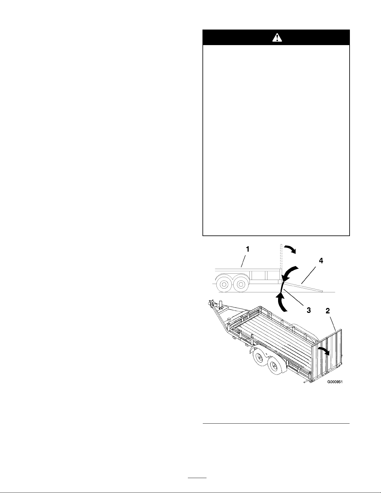
Loading Machines
Use extreme caution when loading units on trailers
or tr uc ks . One full width ramp that is wide enough
to extend bey ond the rear tires is recommended
instead of indi vidual ramps for eac h side of the
unit ( Figure 26 ). T he lo w er rear section of the
tractor frame extends bac k betw een the rear
wheels and ser v es as a stop for tipping bac kw ard.
Ha ving a full width ramp pro vides a surface for the
frame members to contact if the unit star ts to tip
bac kw ard. If it is not possible to use one full width
ramp , use enough indi vidual ramps to sim ulate a
full width contin uous ramp .
T he ramp should be long enough so that the
angles do not ex ceed 15 deg rees ( Figure 26 ). A
stee per angle ma y cause mo w er components to g et
caught as the unit mo v es from ramp to trailer or
tr uc k. Stee per angles ma y also cause the unit to tip
bac kw ard. If loading on or near a slope , position
the trailer or tr uc k so it is on the do wn side of the
slope and the ramp extends up the slope . T his
will minimize the ramp angle . T he trailer or tr uc k
should be as lev el as possible .
Important: Do Not attempt to tur n the unit
while on the ramp; y ou may lose contr ol and
dri v e of f the side.
Loading a unit onto a trailer or tr uck
incr eases the possibility of backw ard
tip-o v er and could cause serious injur y or
death.
• Use extr eme caution when operating a
unit on a ramp .
• Use onl y a sing le, full width ramp; Do
Not use indi vidual ramps f or each side
of the unit.
• If indi vidual ramps must be used, use
enough ramps to cr eate an unbr ok en
ramp surf ace wider than the unit.
• Do not ex ceed a 15 deg r ee ang le betw een
ramp and g r ound or betw een ramp and
trailer or tr uck.
• A v oid sudden acceleration while dri ving
unit up a ramp to a v oid tipping backw ard.
• A v oid sudden deceleration while backing
unit do wn a ramp to a v oid tipping
backw ard.
A v oid sudden acceleration when dri ving up a ramp
and sudden deceleration when bac king do wn a
ramp . Both maneuv ers can cause the unit to tip
bac kw ard.
Figure 26
1. Trailer 3. Not greater than
15 degrees
2. Full width ramp 4. Full width ramp—side view
29
Page 30
Using the Z Stand®
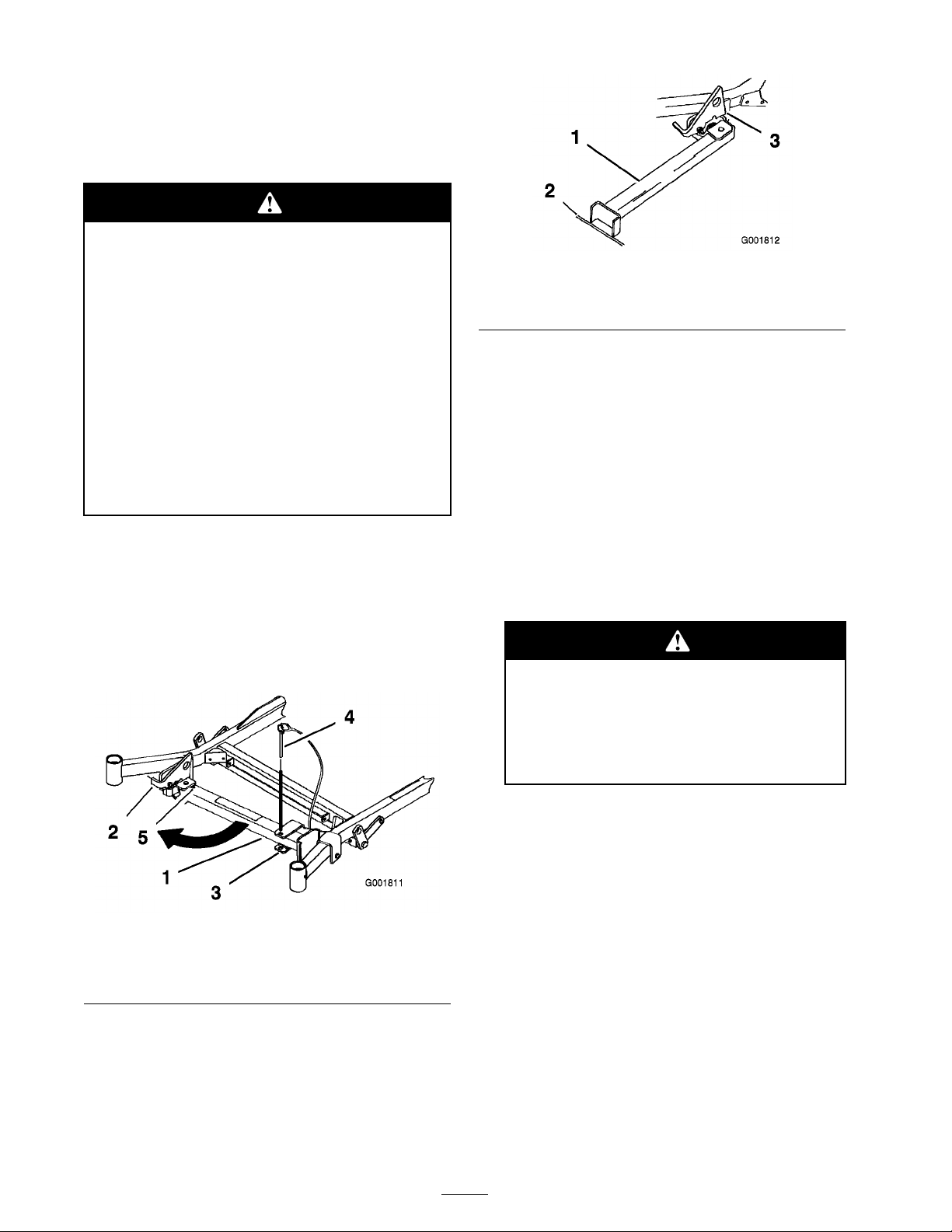
T he Z Stand raises the front end of the mac hine
to allo w y ou to clean the mo w er and remo v e the
blades .
T he machine could f all onto someone and
cause serious injur y or death.
• Use extr eme caution when operating the
machine on the Z Stand.
1. Z Stand (Positioned in slot)
2. Crack in side walk or turf
Figure 28
3. Latch resting on pivot tab
• Use onl y f or cleaning the mo w er and
r emo ving the blades.
• Do not k eep the machine on the Z Stand
f or extended periods of time.
• Al w ays tur n the engine of f, set the
par king brak e, and r emo v e the k ey
bef or e perf or ming an y maintenance to
the mo w er .
Driving up onto the Z Stand
Important: Use the Z Stand on a lev el
surf ace.
1. Raise the mo w er to the transpor t position.
2. R emo v e the brac k et pin ( Figure 27 ).
4. Set the foot of stand on the g round and rest
the latc h on the pi v ot tab ( Figure 28 ).
5. Star t the engine and put it at half throttle .
Note: F or best results , place the foot of
stand into seams in sidew alks or into the turf
( Figure 28 ).
6. Dri v e onto the stand. Stop when the latc h
drops o v er the tab into the loc k ed position
( Figure 28 ). Once onto the stand, eng ag e the
parking brak e and tun off the engine .
7. Choc k or bloc k the dri v e wheels .
P ar king brak e may not hold machine
par k ed on Z Stand and could cause
per sonal injur y or pr oper ty dama ge.
Do not par k on Z Stand unless wheels
ar e chock ed or block ed.
Figure 27
1. Z Stand 4. Bracket Pin
2. Latch 5. Bottom of slot
3. Bracket
3. Raise the latc h. Swing the stand foot out
front and slide stand to w ard mac hine , into the
bottom of slot ( Figure 27 and Figure 28 ).
8. P erfor m the maintenance .
Driving off the Z Stand
1. R emo v e the c hoc ks or bloc ks .
2. Raise the latc h to the unloc k ed position
( Figure 29 ).
30
Page 31
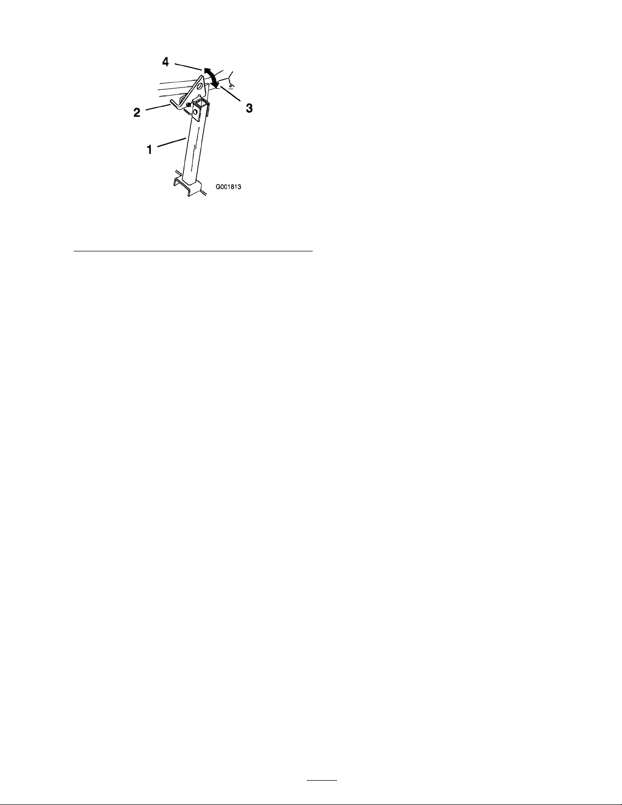
Figure 29
1. Z Stand 3. Locked position
2. Latch 4. Unlocked position
Mowing Direction
Alter nate mo wing direction to k ee p the g rass
standing straight. T his also helps disperse clippings
whic h enhances decomposition and fer tilization.
Mow at Correct Intervals
Nor mally , mo w ev er y four da ys . But remember ,
g rass g ro ws at different rates at different times .
So to maintain the same cutting height, whic h is a
g ood practice , mo w more often in early spring . As
the g rass g ro wth rate slo ws in mid summer , mo w
less frequently . If y ou cannot mo w for an extended
period, first mo w at a high cutting height; then
mo w ag ain tw o da ys later at a lo w er height setting .
3. Star t the engine and place it at half throttle .
Diseng ag e the parking brak e .
4. Slo wly dri v e bac kw ards off of the stand.
5. R etur n the stand to its rest position ( Figure 27 ).
Operating Tips
Fast Throttle Setting
F or best mo wing and maxim um air circulation,
operate the engine at the fast throttle position. Air
is required to thoroughly cut g rass clippings , so
do not set the height-of-cut so lo w as to totally
sur round the mo w er b y uncut g rass . Alw a ys tr y to
ha v e one side of the mo w er free from uncut g rass ,
whic h allo ws air to be dra wn into the mo w er .
Cutting a Lawn for the First Time
Cut g rass slightly long er than nor mal to ensure the
cutting height of the mo w er does not scalp any
unev en g round. Ho w ev er , the cutting height used
in the past is g enerally the best one to use . W hen
cutting g rass long er than six inc hes tall, y ou ma y
w ant to cut the la wn twice to ensure an acce ptable
quality of cut.
Cut 1/3 of the Grass Blade
It is best to cut only about 1/3 of the g rass blade .
Cutting more than that is not recommended unless
g rass is sparse , or it is late fall when g rass g ro ws
more slo wly .
Cutting Speed
T o impro v e cut quality , use a slo w er g round speed
in cer tain conditions .
Avoid Cutting Too Low
If the cutting width of the mo w er is wider than the
mo w er y ou previously used, raise the cutting height
to ensure that unev en turf is not cut too shor t.
Long Grass
If the g rass is ev er allo w ed to g ro w slightly long er
than nor mal, or if it contains a high deg ree of
moisture , raise the cutting height higher than usual
and cut the g rass at this setting . T hen cut the g rass
ag ain using the lo w er , nor mal setting .
When Stopping
If the mac hine’ s forw ard motion m ust be stopped
while mo wing, a clump of g rass clippings ma y
drop onto y our la wn. T o a v oid this , mo v e onto a
previously cut area with the blades eng ag ed.
Keep the Underside of the Mower
Clean
Clean clippings and dir t from the underside of the
mo w er after eac h use . If g rass and dir t build up
inside the mo w er , cutting quality will ev entually
become unsatisfactor y .
Blade Maintenance
Maintain a shar p blade throughout the cutting
season because a shar p blade cuts cleanly without
tearing or shredding the g rass blades . T earing and
31
Page 32

shredding tur ns g rass bro wn at the edg es , whic h
slo ws g ro wth and increases the c hance of disease .
Chec k the cutter blades daily for shar pness , and
for any w ear or damag e . File do wn any nic ks
and shar pen the blades as necessar y . If a blade is
damag ed or w or n, re place it immediately with a
g en uine TOR O re placement blade .
32
Page 33

Maintenance
Recommended Maintenance Schedule(s)
Maintenance Service
Interval
After the rst 8 operating
hours
After the rst 25
operating hours
After the rst 50
operating hours
Before each use or daily
Every 25 hours
Every 50 hours
Maintenance Procedure
• Check cooling system level.
• Adjust the drive belts.
• Check the hydraulic uid.
• Change the hydraulic lter and oil.
• Change the engine oil.
• Change the engine oil lter.
• Test the safety system.
• Check the engine oil.
• Check cooling system level.
• Clean the cooling system.
• Inspect the belts for cracks and wear.
• Check the mower blades.
• Clean the mower deck.
• Grease the mower deck and spindles.
• Grease the mower belt idler arm.
• Grease the pump belt idler arm.
• Grease the drive belt idler arm.
• Grease the brake lever.
• Check the hydraulic uid.
• Check the tire pressure.
• Adjust the drive belts.
• Check the pump drive belt.
• Check the alternator belt.
• Change the engine oil.
Every 100 hours
Every 150 hours
Every 200 hours
Every 500 hours
Every 600 hours
Every 800 hours
Yearly
Every 2 years
• Check the cooling system hoses.
• Check the hydraulic hoses.
• Lubricate the machine with light oil (Refer to Lubrication).
• Replace the primary air lter.
• Change the engine oil lter.
• Grease the brake pivot.
• Check the wheel hub slotted nut.
• Adjust the caster pivot bearing.
• Replace the fan hydraulic lter.
• Replace the safety air lter.
• Replace the fuel lter.
• Grease the front caster pivots (more often in dirty or dusty conditions).
• Change the hydraulic lter and oil.
• Change the engine coolant.
Important: R efer to y our Engine Operator’ s Man ual f or additional maintenance pr ocedur es.
33
Page 34
If y ou lea v e the k ey in the ignition s witch, someone could accidentl y star t the engine and
seriousl y injur e y ou or other bystander s.
R emo v e the k ey fr om the ignition and disconnect the wir e fr om the spar k plug(s) bef or e y ou
do an y maintenance. Set the wir e aside so that it does not accidentall y contact the spar k plug .
Lubrication
Greasing and Lubrication
Lubricate the mac hine when sho wn on the Chec k
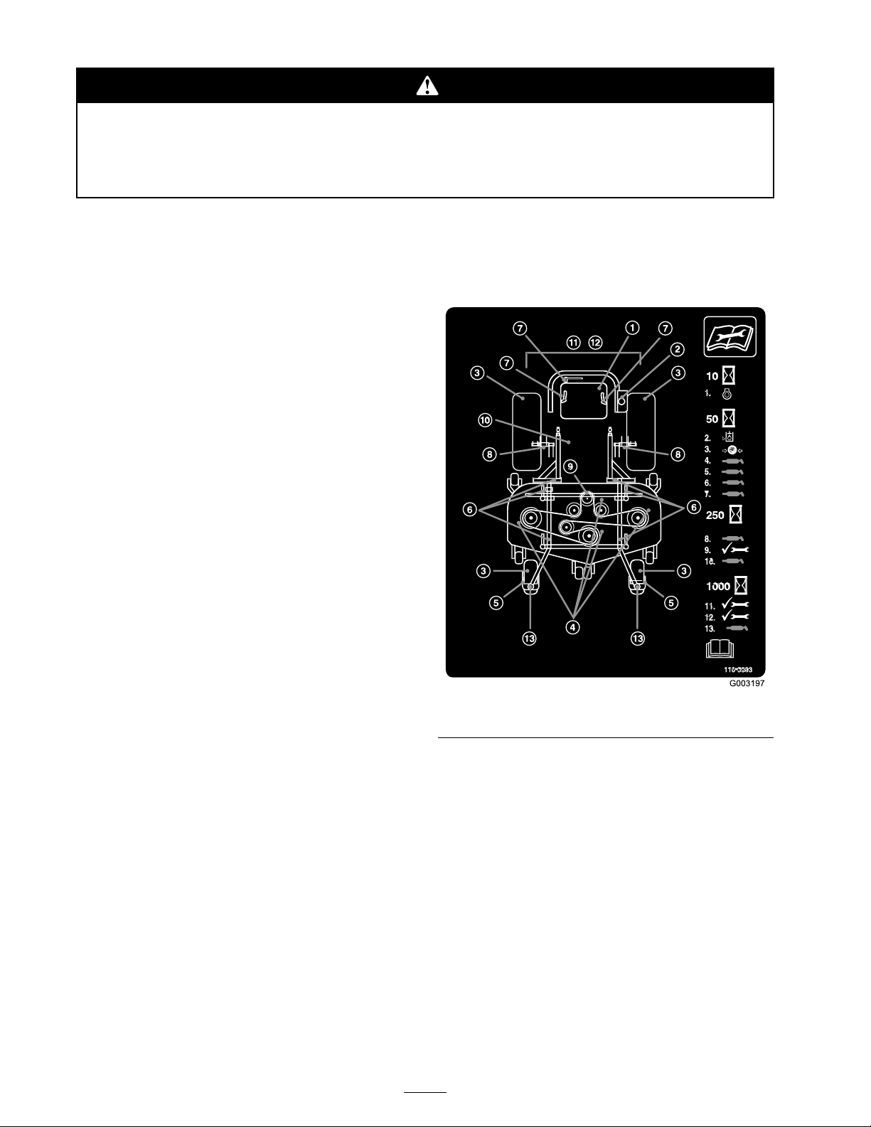
Ser vice R eference Aid decal ( Figure 30 ). Grease
more frequently when operating conditions are
extremely dusty or sandy .
Grease T ype: General-pur pose g rease .
How to Grease
1. Diseng ag e the PTO , mo v e the motion control
lev ers to the neutral loc k ed position and set
the parking brak e .
2. Stop the engine , remo v e the k ey , and w ait for
all mo ving par ts to stop before lea ving the
operating position.
3. Clean the g rease fittings with a rag . Mak e
sure to scrape any paint off the front of the
fitting(s).
Where to Add Grease
Lubricate the g rease fittings as sho wn on the
Chec k Ser vice R eference Aid decal ( Figure 30 ).
4. Connect a g rease gun to the fitting . Pump
g rease into the fittings until g rease begins to
ooze out of the bearings .
5. Wipe up any ex cess g rease .
Greasing the Front Caster Pivots
Lubricate the front caster pi v ots once a year .
1. R emo v e the dust cap and adjust the caster
pi v ots . K ee p the dust cap off until g reasing
is done . R efer to Adjusting the Caster Pi v ot
Bearing in Dri v e System Maintenance , pag e 42 .
2. R emo v e the hex plug . T hread a g rease zerk
into the hole .
3. Pump g rease into the zerk until it oozes out
around the top bearing .
4. R emo v e the g rease zerk in the hole . Install the
hex plug and cap .
Figure 30
Greasing the Mower Deck
and Belt Idlers
T he mo w er dec k m ust be lubricated w eekly or
ev er y 25 hours . Grease with No . 2 g eneral pur pose
lithium base or molybden um base g rease .
Important: Mak e sur e cutting unit spindles
ar e full of g r ease w eekl y .
1. Diseng ag e the PTO , mo v e the motion control
lev ers to the neutral loc k ed position and set
the parking brak e .
2. Stop the engine , remo v e the k ey , and w ait for
all mo ving par ts to stop before lea ving the
operating position.
34
Page 35
3. R emo v e the screws and belt co v ers .
4. Grease the three spindle bearings under the
pulleys until g rease comes out the lo w er seals
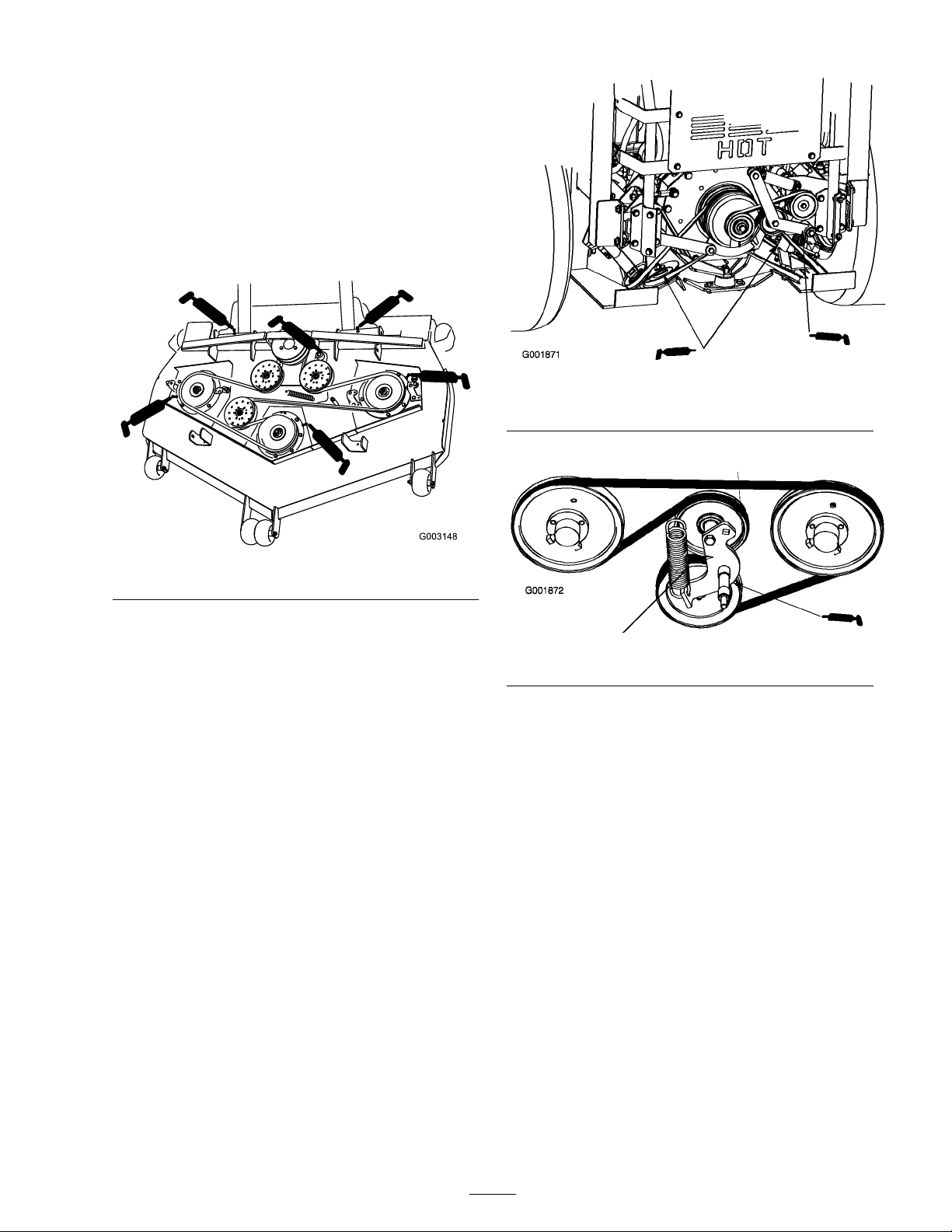
( Figure 31 ).
5. Grease the idler ar m on the mo w er dec k
( Figure 31 ).
6. Grease the fittings on the push ar ms
( Figure 31 ).
Figure 32
1. Left adjustable pulley 2. Back of the machine
3. Grease the pump belt idler ar m.
Figure 31
Where to Add Light Oil or
Spray Lubrication
Lubricate the mac hine in the follo wing areas with
spra y type lubricant or light oil. Lubricate ev er y
150 hours .
• Seat switc h actuator .
• Brak e handle pi v ot.
• Brak e rod bushings .
• Motion control bronze bushings .
Grease the Idler Arms
1. Grease the cooling fan belt idler ar m
( Figure 32 ).
2. Grease the dri v e belt idler ar ms ( Figure 32 ).
Figure 33
Engine Maintenance
Servicing the Air Cleaner
Primar y Filter : Chec k and/or re place after ev er y
200 operating hours or more often in dusty
conditions .
Safety Filter : R e place after ev er y 600 operating
hours .
Note: Ser vice the air cleaner more frequently if
operating conditions are extremely dusty or sandy .
Removing the Filters
1. Diseng ag e the PTO , mo v e the motion control
lev ers to the neutral loc k ed position and set
the parking brak e .
2. Stop the engine , remo v e the k ey , and w ait for
all mo ving par ts to stop before lea ving the
operating position.
35
Page 36
3. Tilt the seat forw ard and remo v e the front
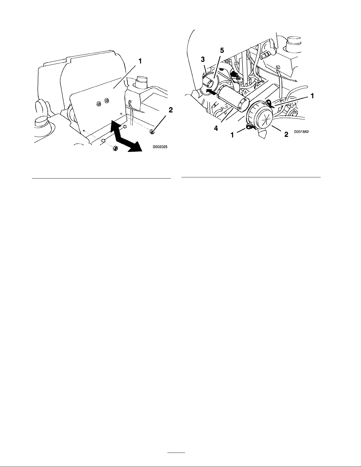
engine panel ( Figure 34 ).
Figure 34
1. Front engine panel
2. Nut
Figure 35
1. Latches 4. Primary lter
2. Air cleaner cover 5. Safety lter
3. Air lter body
4. R elease the latc hes on the air cleaner and pull
the air cleaner co v er off of the air cleaner body
( Figure 35 ).
5. Clean the inside of the air cleaner co v er with
compressed air .
6. Gently slide the primar y filter out of the air
cleaner body ( Figure 35 ). A v oid knoc king the
filter into the side of the body .
7. R emo v e the safety filter only if y ou intend to
re place it.
Important: Nev er attempt to clean the
safety filter . If the safety filter is dir ty ,
then the primar y filter is dama ged and y ou
should r eplace both filter s.
8. Inspect the primar y filter for damag e b y
looking into the filter while shining a bright
light on the outside of the filter . Holes in the
filter will appear as bright spots . If the filter
is damag ed discard it.
Servicing the Primary Filter
1. Do not clean the paper filter . R e place it after
200 operating hours ( Figure 35 ).
2. Inspect the element for tears , an oily film, or
damag e to the r ubber seal.
3. R e place the paper element if it is damag ed.
Servicing the Safety Filter
Do not clean the safety filter . R e place it after
600 operating hours .
Important: Nev er attempt to clean the
safety filter . If the safety filter is dir ty , then
the primar y filter is dama ged and y ou should
r eplace both filter s.
Installing the Filters
Important: T o pr ev ent engine dama ge,
al w ays operate the engine with both air filter s
and co v er installed.
1. If installing new filters , c hec k eac h filter for
shipping damag e . Do not use a damag ed filter .
2. If the safety filter is being re placed, carefully
slide it into the filter body ( Figure 35 ).
3. Carefully slide the primar y filter o v er the safety
filter ( Figure 35 ). Ensure that it is fully seated
b y pushing on the outer rim of the filter while
installing it.
36
Page 37
Important: Do not pr ess on the soft
inside ar ea of the filter .
4. Install the air cleaner co v er with the side
indicated as UP facing up and secure the
latc hes ( Figure 35 ).
5. Install the front engine panel.
Servicing the Engine Oil
Chang e oil after the first 50 operating hours and
then ev er y 150 operating hours thereafter .
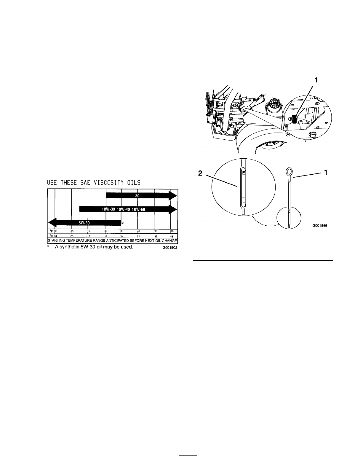
Oil T ype: High-quality deterg ent oil classified “ API
Ser vice CF or CF-4" or higher for diesel engines .
Do not use special additi v es with recommended
oils .
Crankcase Capacity: 3.5 quar ts (3.3 liters)
Viscosity: See the table belo w .
Important: Do not o v erfill the crankcase
with oil because this may cause engine
dama ge. Do not r un the engine with oil
belo w the lo w mar k because the engine
may be dama ged as a r esult.
Figure 36
Checking the Engine Oil Level
Note: Chec k the oil when the engine is cold.
1. Diseng ag e the PTO , mo v e the motion control
lev ers to the neutral loc k ed position and set
the parking brak e .
2. Stop the engine , remo v e the k ey , and w ait for
all mo ving par ts to stop before lea ving the
operating position.
3. Clean around the oil dipstic k ( Figure 37 ) so
dir t cannot fall into the filler hole and damag e
the engine .
4. Pull the oil dipstic k out and wipe the metal end
clean ( Figure 37 ).
5. Slide the oil dipstic k fully into the tube . Pull
the dipstic k out and look at the metal end
( Figure 37 ). If the oil lev el is lo w , slo wly pour
only enough oil into the fill hole to raise the
lev el to the full mark.
Figure 37
1. Oil dipstick 3. Right side of machine
2. Metal end
Changing the Engine Oil
1. Star t the engine and let it r un for fiv e min utes .
T his w ar ms the oil so it drains better .
2. P ark the mac hine on a lev el surface .
3. Diseng ag e the PTO , mo v e the motion control
lev ers to the neutral loc k ed position and set
the parking brak e .
4. Stop the engine , remo v e the k ey , and w ait for
all mo ving par ts to stop before lea ving the
operating position.
5. Place a pan belo w the oil drain. R emo v e the
drain plug and let the oil drain completely
( Figure 41 ).
6. R emo v e the oil filler cap from the top of the
engine ( Figure 39 ). T his will help the oil to
drain.
7. Install the drain plug and tighten it to
25-1/2 ft-lb (35 N•m).
37
Page 38
Note: Dispose of the used oil at a recycling
center .
Adding Engine Oil
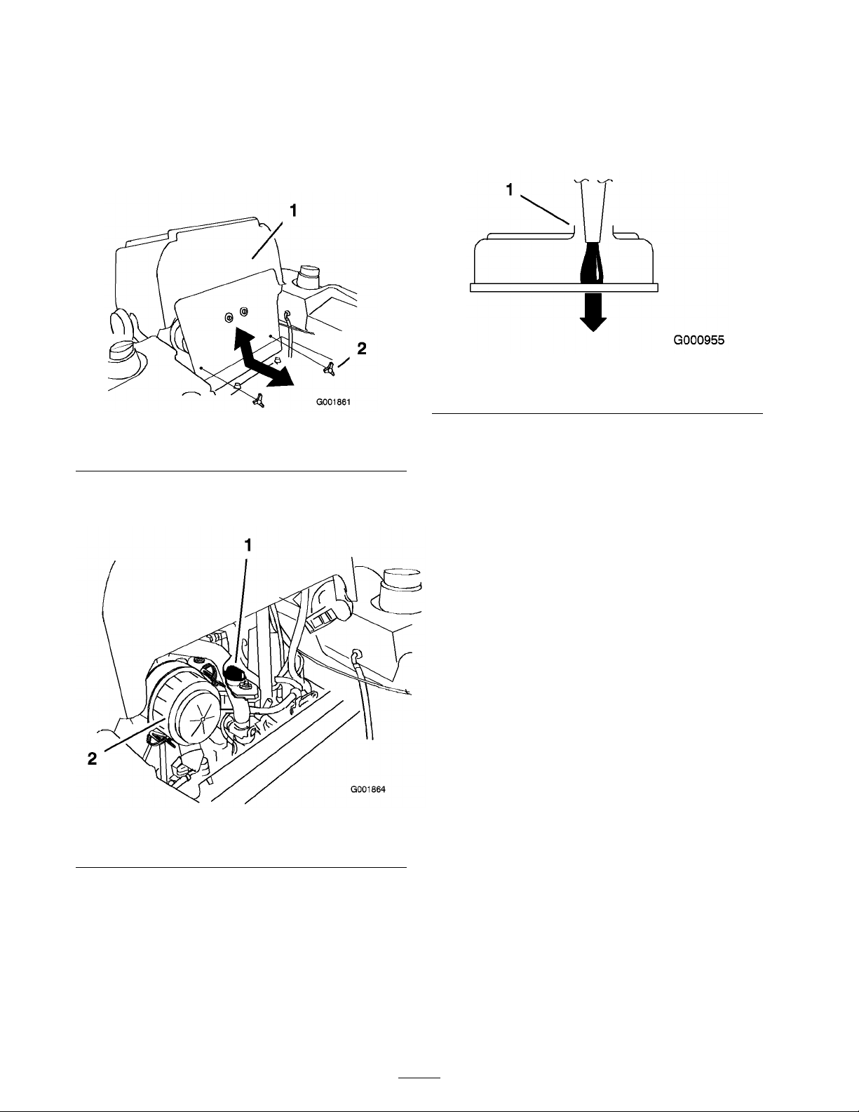
1. Tilt the seat forw ard and remo v e the front
engine panel ( Figure 38 ).
Important: Add the oil v er y slo wl y and
do not block the opening of the filler hole
( Figur e 40 ). If y ou add oil too f ast or block
the hole, the oil could back up and f oul the
air intak es, causing engine dama ge.
Figure 40
1. Note the clearance left in the ller opening.
Figure 38
1. Front engine panel 2. Knob
2. R emo v e the oil filler cap and the dipstic k
( Figure 39 ).
Figure 39
1. Engine
2. Oil ll cap
3. T o add oil to the engine , locate and use a hose
and funnel for adding oil.
4. Add oil slo wly , c hec king the lev el with the
dipstic k frequently until the lev el reac hes the
upper hole on the dipstic k. F or the cor rect
oil type and viscosity to use in different
temperature conditions , refer to Ser vicing the
Engine Oil in Engine Maintenance , pag e 35 , ).
5. R e place the dipstic k and install the front engine
panel.
6. Star t the engine and r un it at idle for 5 min utes .
7. Shut off the engine .
8. W ait 3 min utes and c hec k the oil lev el.
9. Add oil, if required, to bring the lev el to the
upper hole on the dipstic k.
10. R e place the dipstic k and , filler cap , and the
front engine panel.
11. Chec k for leaks .
Important: Do not o v erfill the crankcase
with oil because this may cause engine
dama ge.
Changing the Engine Oil Filter
R e place the oil filter after the first 50 operating
hours and then ev er y 200 operating hours
thereafter .
1. Drain the oil from the engine; refer to
Changing the Engine Oil.
Place a drip pan beneath the oil drip tra y to
recei v e oil from the oil filter and oil passag es
in the engine .
2. T ur n the filter countercloc kwise to remo v e it
( Figure 42 and Figure 42 ).
Note: Dispose of the oil filter properly .
R ecycle in accordance with local codes .
38
Page 39
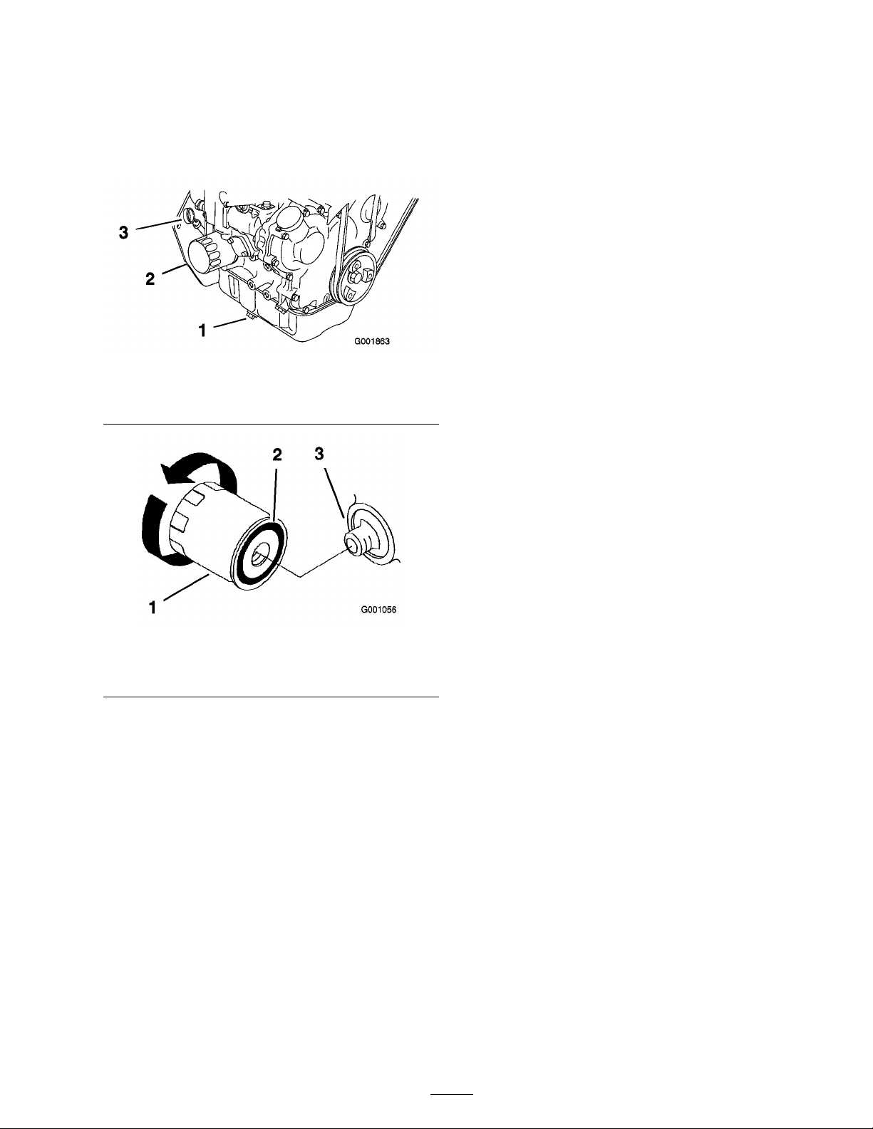
3. Before installing the filter , lightly oil the g ask et
on the filter with fresh, clean oil. Screw the
filter on b y hand until the g ask et contacts the
oil filter adapter . Tighten 1/2 to 3/4 tur n more .
4. Add oil; refer to Adding Engine Oil.
3. Disconnect the neg ati v e batter y cable; R efer to
R emo ving the Batter y .
4. Allo w the mac hine to cool do wn.
5. Place a drain pan under the fuel filter and
loosen the drain plug 1 tur n.
6. Let the w ater drain. If necessar y , operate the
priming pump to drain w ater , but only until
fuel flo ws from the filter .
7. Tighten the drain plug when fuel begins to
flo w .
8. Bleed the air from the fuel line b y priming the
fuel system; refer to Priming the Fuel System.
Figure 41
1. Drain plug 3. Dip stick
2. Oil lter
Figure 42
1. Oil lter 3. Adapter
2. Gasket
Fuel System
Maintenance
Servicing the Fuel Filter
Changing the Fuel Filter
R e place the fuel filter after ev er y 800 operating
hours or yearly , whic hev er occurs first.
Nev er install a dir ty filter if it is remo v ed from the
fuel line .
1. Allo w the mac hine to cool do wn.
2. Diseng ag e the PTO , mo v e the motion control
lev ers to the neutral loc k ed position and set
the parking brak e .
3. Stop the engine , remo v e the k ey , and w ait for
all mo ving par ts to stop before lea ving the
operating position.
4. Close the fuel shut-off v alv e .
5. Disconnect the sensor wire .
6. R emo v e the drain plug and discard the o-ring
( Figure 43 ).
7. R emo v e the filter .
8. Install a new filter on b y hand until the g ask et
contacts the housing, then tighten an extra 1/3
of a tur n ( Figure 43 ).
Draining Water from the Fuel Filter
If the w ater in fuel light comes on stop the engine
and drain the w ater from the fuel filter .
1. Diseng ag e the PTO , mo v e the motion control
lev ers to the neutral loc k ed position and set
the parking brak e .
2. Stop the engine , remo v e the k ey , and w ait for
all mo ving par ts to stop before lea ving the
operating position.
9. Install the drain plug with a new O-ring and
connect the sensor wire .
10. Bleed the air from the fuel line b y priming the
fuel system, refer to Priming the Fuel System.
11. Open fuel shut-off v alv e .
12. Star t the engine and c hec k for leaks .
39
Page 40
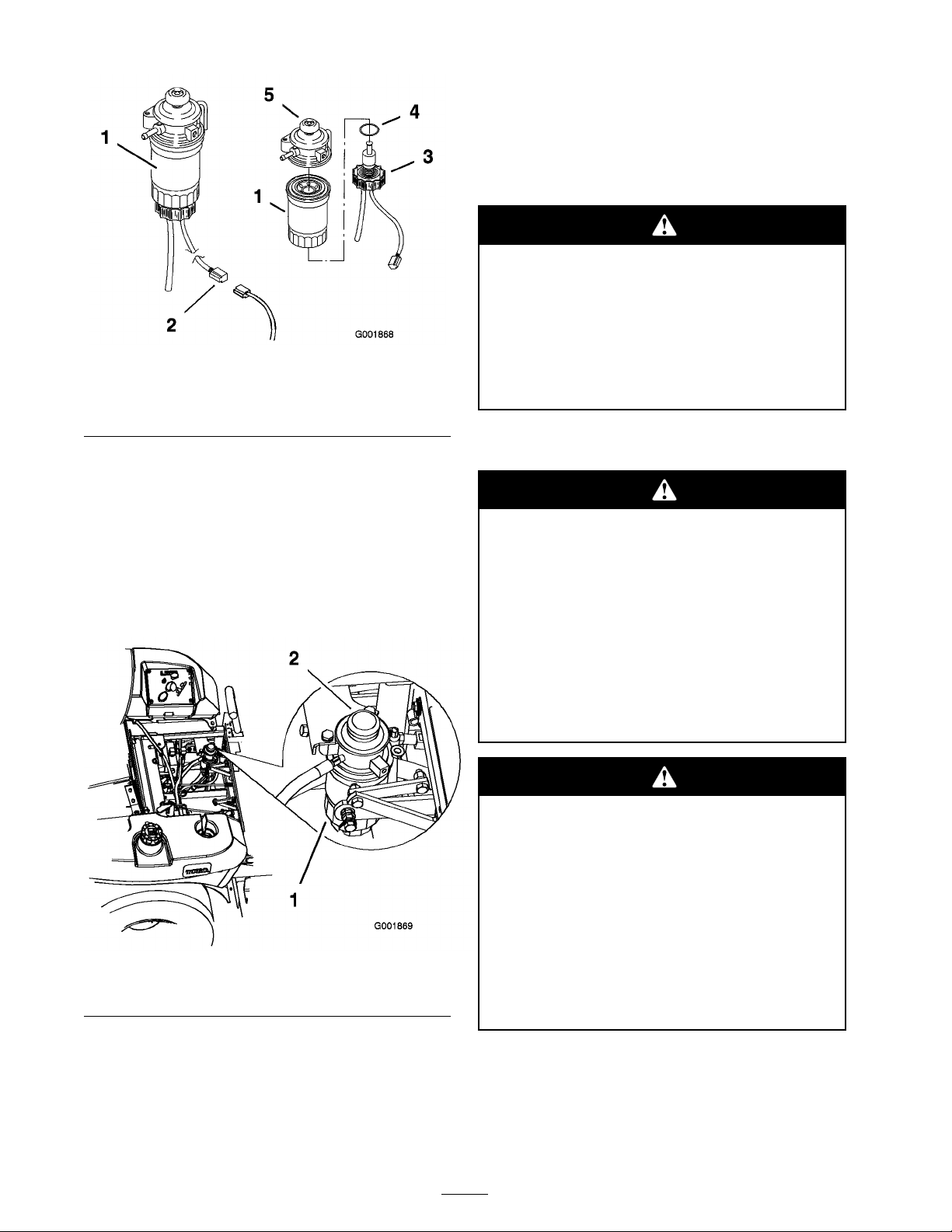
Figure 43
1. Fuel lter
2. Sensor wire
3. Drain plug
4. O-ring
5. Metal primer button
Priming the Fuel System
T he primer pump is the g old metal button on top
of the fuel filter ( Figure 44 ).
T o bleed air from the fuel system, push do wn on
the primer pump until resistance becomes fir m.
T his should tak e about 10-15 pushes on the primer
pump .
Electrical System
Maintenance
Servicing the Battery
Batter y electr ol yte contains sulfuric acid
which is a deadl y poison and causes sev er e
bur ns.
Do not drink electr ol yte and a v oid contact
with skin, ey es or clothing . W ear safety
g lasses to shield y our ey es and r ub ber g lo v es
to pr otect y our hands.
Removing the Battery
Batter y ter minals or metal tools could shor t
a gainst metal machine components causing
spar ks. Spar ks can cause the batter y gasses
to explode, r esulting in per sonal injur y .
• W hen r emo ving or installing the batter y ,
do not allo w the batter y ter minals to
touch an y metal par ts of the machine.
Figure 44
1. Fuel lter 2. Gold metal primer pump
Servicing the Fuel Tank
Do not attempt to drain the fuel tank. Ensure that
an A uthorized Ser vice Dealer drains the fuel tank
and ser vices any components of the fuel system.
• Do not allo w metal tools to shor t betw een
the batter y ter minals and metal par ts of
the machine.
Incor r ect batter y ca ble r outing could
dama ge the machine and ca bles causing
spar ks. Spar ks can cause the batter y gasses
to explode, r esulting in per sonal injur y .
• Al w ays Disconnect the negati v e (black)
batter y ca ble bef or e disconnecting the
positi v e (r ed) ca ble.
• Al w ays R econnect the positi v e (r ed)
batter y ca ble bef or e r econnecting the
negati v e (black) ca ble.
1. Diseng ag e the PTO , mo v e the motion control
lev ers to the neutral loc k ed position and set
the parking brak e .
40
Page 41
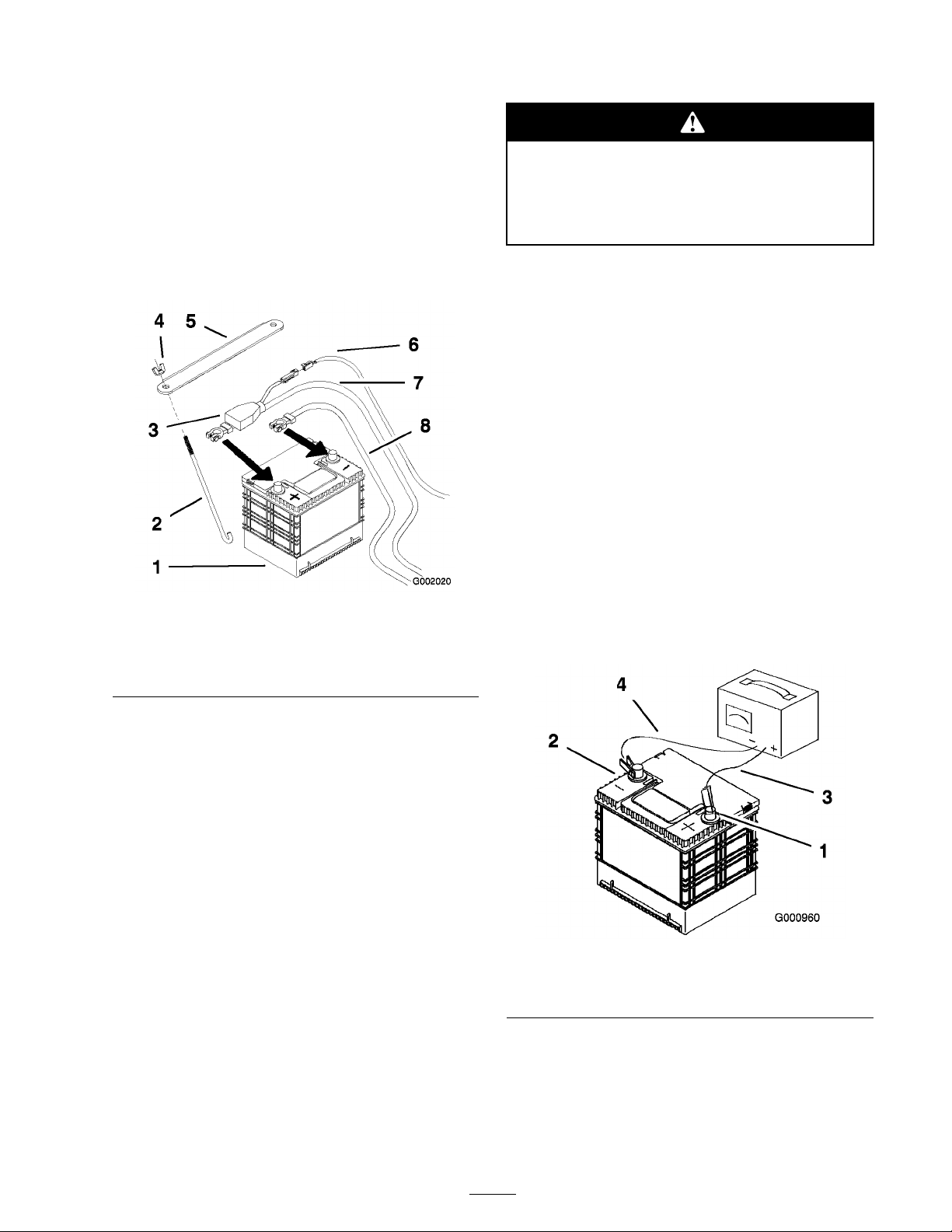
2. Stop the engine , remo v e the k ey , and w ait for
all mo ving par ts to stop before lea ving the
operating position.
Charging the Battery
3. Unlatc h the seat and tilt the seat up .
4. First disconnect the neg ati v e batter y cable from
the neg ati v e (-) batter y ter minal ( Figure 45 ).
5. Slide the red ter minal boot off the positi v e
(red) batter y ter minal. T hen remo v e the
positi v e (red) batter y cable ( Figure 45 ).
Figure 45
1. Battery
2. J-bolts 6. Ground wire
3. Terminal boot
4. Wing nut (1/4 inch) 8. Black (-) cable
5. Battery clamp
7. Red (+) cable
Charging the batter y pr oduces gasses that
can explode.
Nev er smok e near the batter y and k eep
spar ks and flames a w ay fr om batter y .
Important: Al w ays k eep the batter y
full y charged (1.265 specific g ra vity). T his
is especiall y impor tant to pr ev ent batter y
dama ge when the temperatur e is belo w 32°F
(0°C).
1. Mak e sure the filler caps are installed in batter y .
Charg e batter y for 10 to 15 min utes at 25 to 30
amps or 30 min utes at 10 amps .
2. W hen the batter y is fully c harg ed, unplug
the c harg er from the electrical outlet, then
disconnect the c harg er leads from the batter y
posts ( Figure 46 ).
3. Install the batter y in the mac hine and connect
the batter y cables , refer to Installing the
Batter y .
Note: Do not r un the mac hine with the
batter y disconnected, electrical damag e ma y
occur .
6. R emo v e the batter y .
Installing the Battery
1. P osition batter y in the tra y with the ter minal
posts opposite from the h y draulic tank
( Figure 45 ).
2. First, install the positi v e (red) batter y cable to
positi v e (+) batter y ter minal.
3. T hen install the neg ati v e batter y cable and
g round wire to the neg ati v e (-) batter y ter minal.
4. Secure the cables with 2 bolts (1/4 x 3/4 inc h),
2 w ashers (1/4 inc h), and 2 loc kn uts (1/4 inc h)
( Figure 45 ).
5. Slide the red ter minal boot onto the positi v e
(red) batter y post.
6. Secure the batter y with J-bolts , hold do wn
clamp , 2 w ashers (1/4 inc h), and 2 wing n uts
(1/4 inc h) ( Figure 45 ).
Figure 46
1. Positive Battery Post
2. Negative Battery Post
3. Red (+) Charger Lead
4. Black (-) Charger Lead
Servicing the Fuses
T he electrical system is protected b y fuses . It
requires no maintenance , ho w ev er , if a fuse blo ws
c hec k component/circuit for malfunction or shor t.
41
Page 42
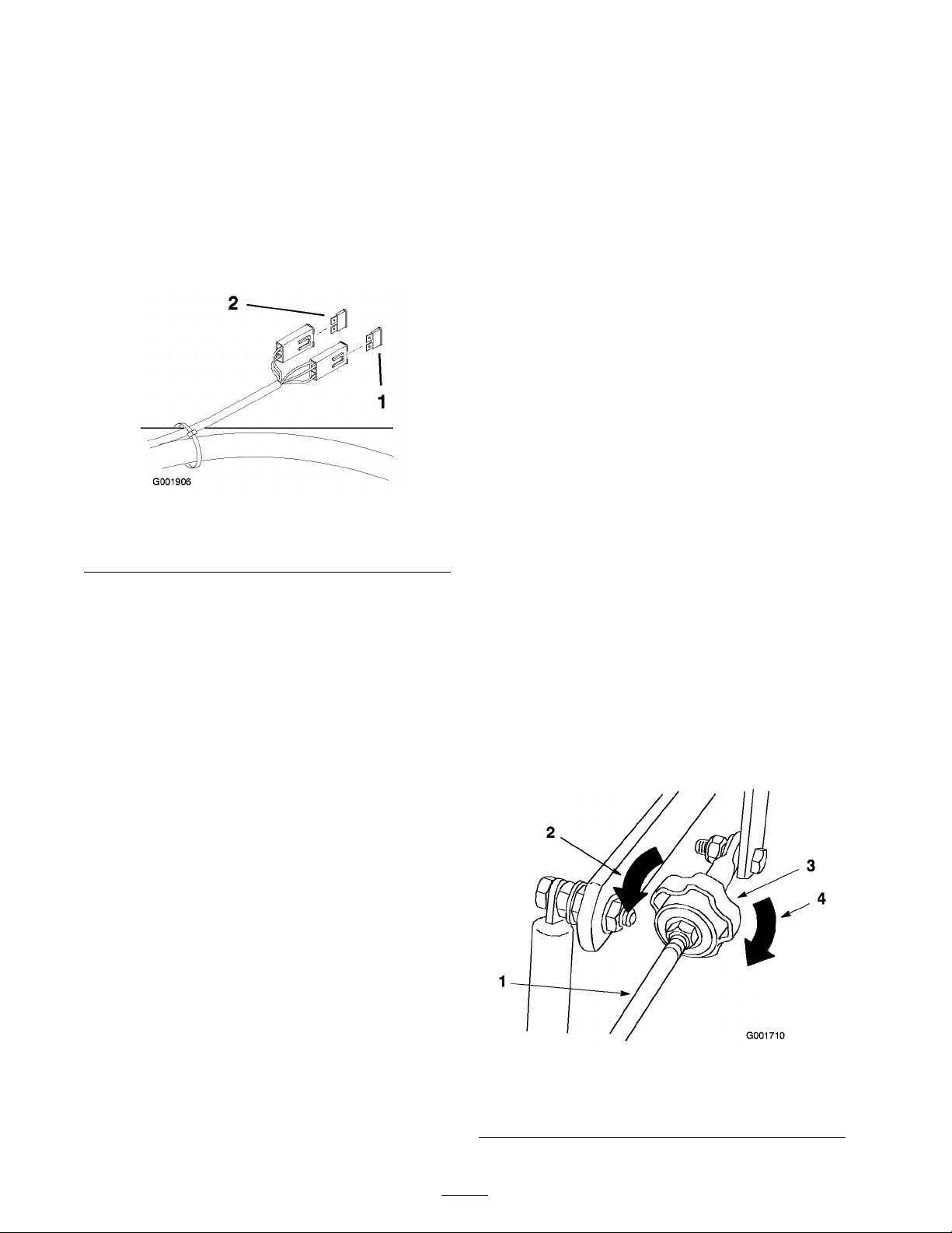
Fuse: Main/Ignition -20 amp , blade-type
Glo w plug/Alter nator -40 amp , blade-type
1. T o g ain access to the main fuse , unlatc h the
seat and tilt the seat forw ard. T o g ain access to
the fan and alter nator fuses , raise the seat and
tilt the engine co v er forw ard.
2. T o re place a fuse , pull out on the fuse to
remo v e it ( Figure 47 ).
Figure 47
1. Glow plug/Alternator40 amp
2. Main/Ignition-20 amp
Drive System
Maintenance
Adjusting the Tracking
T he mac hine has a knob for adjusting the trac king
located under the seat.
Important: Adjust the handle neutral and
h y draulic pump neutral bef or e adjusting
the tracking . R efer to Adjusting the Handle
Neutral in Contr ols System Maintenance ,
pa ge 49 and Adjusting the Hy draulic Pump
Neutral in Hy draulic System Maintenance ,
pa ge 50 .
1. Push both control lev ers forw ard the same
distance .
2. Chec k if the mac hine pulls to one side . If it
does , stop the mac hine and set the parking
brak e .
3. Unlatc h the seat and tilt the seat forw ard to
access the trac king knob .
Note: Deter mine the left and right sides
of the mac hine from the nor mal operating
position.
4. T o mak e the mac hine g o right, tur n the knob
to w ards the rightside of the mac hine . R efer to
Figure 48 .
5. T o mak e the mac hine g o left, tur n the knob
to w ards the leftside of the mac hine . R efer to
Figure 48 .
6. R e peat adjustment until the trac king is cor rect.
Figure 48
1. Tracking knob 4. Turn this way to track right
2. Hydraulic tank 5. Turn this way to track left
3. Hydraulic pumps
42
Page 43
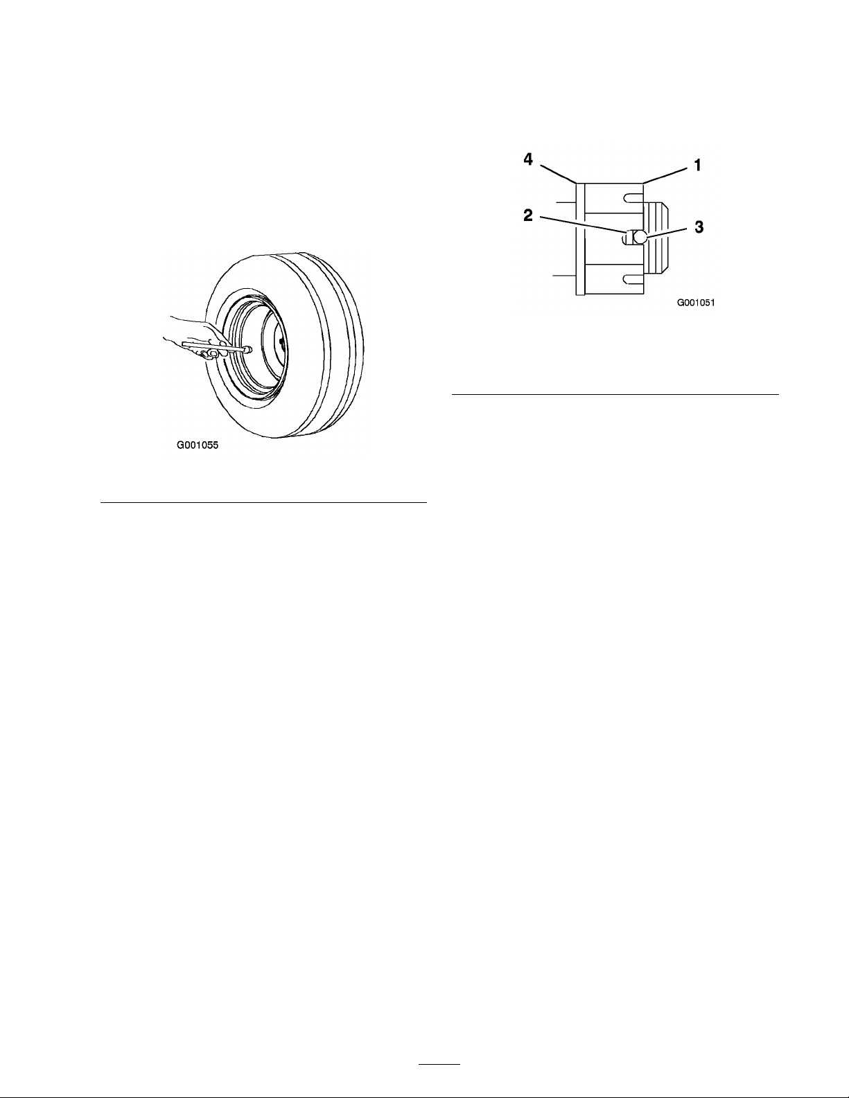
Checking the Tire Pressure
Chec k the pressure at the v alv e stem after ev er y
50 operating hours or monthly , whic hev er occurs
first ( Figure 49 ).
Maintain the air pressure in the front and rear tires
at 13 psi (90 kP a). Unev en tire pressure can cause
unev en cut. Chec k the tires when they are cold to
g et the most accurate pressure reading .
8. Tighten the n ut until the next set of slots line
up with the hole in the shaft ( Figure 50 ).
9. R e place the cotter pin.
Figure 50
1. Slotted Nut 3. Hole in threaded shaft
2. Two threads or less
showing
4. Washer (if needed)
Adjusting the Caster Pivot
Figure 49
Checking the Wheel Hub
Slotted Nut
Chec k after ev er y 500 operating hours .
T he slotted n ut needs to be tor qued to 125 ft-lb
(170 N•m).
1. Diseng ag e the PTO , mo v e the motion control
lev ers to the neutral loc k ed position and set
the parking brak e .
2. Stop the engine , remo v e the k ey , and w ait for
all mo ving par ts to stop before lea ving the
operating position.
3. R emo v e the cotter pin.
4. T or que the slotted n ut to 125 ft-lb (170 N•m)
( Figure 50 ).
Bearing
Chec k after ev er y 500 operating hours or at
storag e , whic h ev er comes first.
1. Diseng ag e the PTO , mo v e the motion control
lev ers to the neutral loc k ed position and set
the parking brak e .
2. Stop the engine , remo v e the k ey , and w ait for
all mo ving par ts to stop before lea ving the
operating position.
3. R emo v e the dust cap from caster and tighten
loc k n ut ( Figure 51 ).
4. Tighten the loc kn ut until the spring w ashers
are flat and then bac k off a 1/4 tur n to properly
set the pre-load on the bearings ( Figure 51 ).
Important: Mak e sur e spring w asher s
ar e installed cor r ectl y as sho wn in
Figur e 51 .
5. Install the dust cap ( Figure 51 ).
5. Chec k the distance from bottom of slot in n ut
to inside edg e of hole . T w o threads or less
should be sho wing ( Figure 50 ).
6. If more than tw o threads are sho wing remo v e
n ut and install w asher betw een hub and n ut.
7. T or que the slotted n ut to 125 ft-lb . (170 N•m)
( Figure 50 ).
43
Page 44
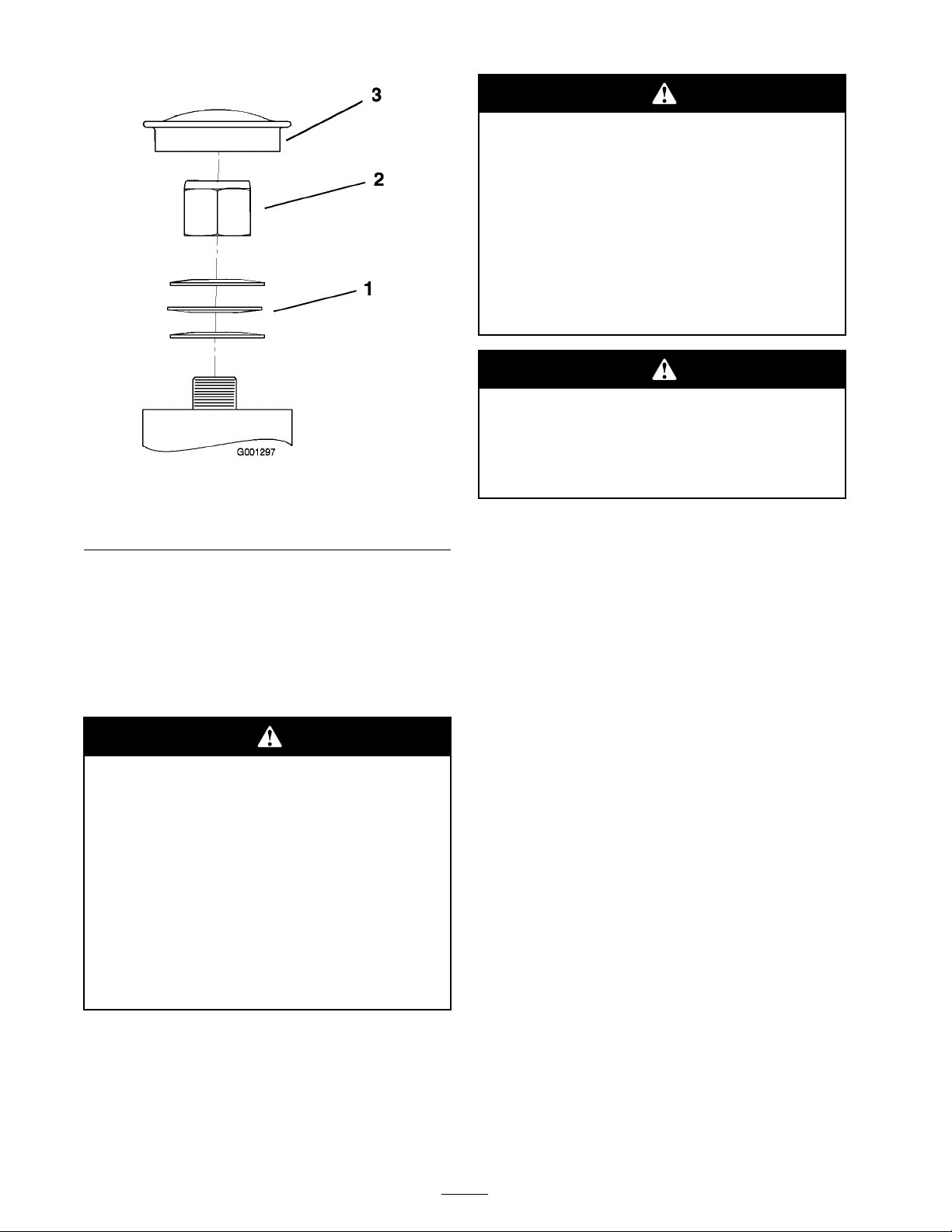
R otating shaft and f an can cause per sonal
injur y .
• Do not operate the machine without the
co v er s in place.
• K eep finger s, hands and clothing clear of
r otating f an and dri v e shaft.
• Shut of f the engine and r emo v e
the ignition k ey bef or e perf or ming
maintenance.
Sw allo wing engine coolant can cause
poisoning .
• Do not s w allo w engine coolant.
Figure 51
1. Spring Washers
2. Lock Nut
3. Dust Cap
Cooling System
Maintenance
Servicing the Cooling System
Discharge of hot pr essuriz ed coolant or
touching hot radiator and sur r ounding par ts
can cause sev er e bur ns.
• Do not r emo v e the radiator cap when
the engine is hot. Al w ays allo w the
engine to cool at least 15 min utes or
until the radiator cap is cool enough to
touch without bur ning y our hand bef or e
r emo ving the radiator cap .
• Do not touch radiator and sur r ounding
par ts that ar e hot.
• K eep out of r each fr om childr en and pets.
Checking the Radiator Coolant
Chec k the cooling system lev el daily .
Chec k the cooling system hoses ev er y 100 hours .
Fluid T ype: 50/50 mix of extended life
antifreeze/Dex-Cool® and w ater
Cooling System Capacity: 128 ounces (3.8 l)
Note: Do not open the radiator cap . Doing this
ma y induce air into the cooling system.
1. P osition the mac hine on a lev el surface , stop
the engine , and set the parking brak e .
2. Unlatc h the seat and tilt the seat up .
3. With the engine cool, c hec k the o v erflo w bottle
lev el. T he fluid needs to be up to the bump on
the outside of the o v erflo w bottle ( Figure 52 ).
4. If the coolant lev el is lo w , add a 50/50 mix of
extended life antifreeze/Dex-Cool® and w ater
to the o v erflo w bottle ( Figure 52 ).
5. Add the 50/50 coolant mix to the o v erflo w
bottle and fill it to the indicator line on the
bottle ( Figure 52 ).
44
Page 45
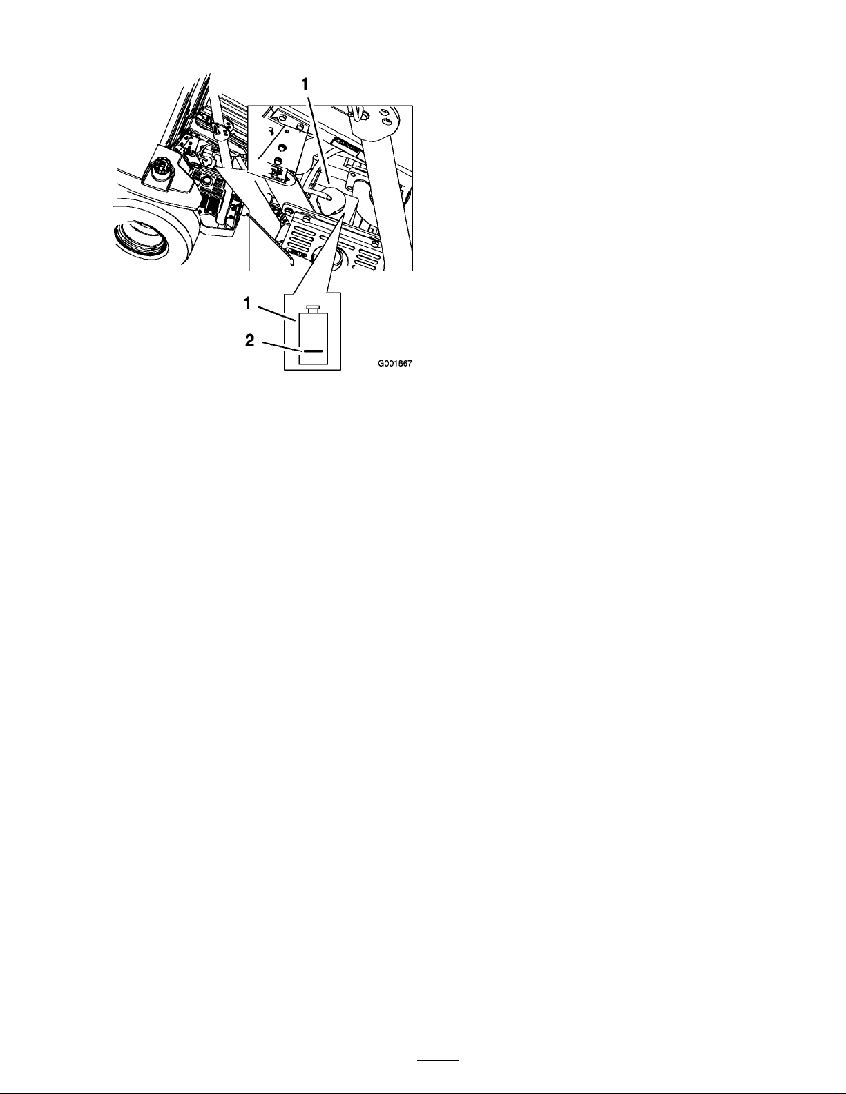
Figure 52
1. Antifreeze overow bottle 2. Indicator line on side of
overow bottle
Cleaning the Cooling System
Clean the cooling system daily before eac h use .
1. P osition the mac hine on a lev el surface , stop
the engine , and set the parking brak e .
Important: Bef or e star ting the engine,
clean g rass fr om the pump dri v e belt
compar tment. Check mor e often in dr y
conditions.
2. Unlatc h the seat, tilt the seat up and raise the
r ubber flap abo v e the dri v e belt compar tment.
3. R emo v e debris from the dri v e belt
compar tment and h y draulic pumps .
4. R emo v e debris from the screen on the engine
co v er .
5. Tilt the engine co v er forw ard.
6. R emo v e debris from the radiator core and
engine .
Contact an A uthorized Ser vice Dealer for c hanging
the coolant.
Brake Maintenance
Adjusting the Parking Brake
1. Diseng ag e the brak e lev er (lev er do wn).
2. Measure the length of the spring . T he
measurement should be 2-3/4 inc h (70 mm)
betw een the w ashers ( Figure 53 ).
3. If an adjustment is necessar y , loosen the jam
n ut belo w the spring and tighten the n ut
directly belo w the y ok e ( Figure 53 ). T ur n the
n ut until the cor rect measurement is obtained.
Tighten the tw o n uts tog ether and re peat on
the opposite side of the unit.
4. T ur n the n uts cloc kwise to shor ten the spring
length and countercloc kwise to lengthen the
spring .
5. Eng ag e the parking brak e , lev er up .
6. Measure the distance betw een the spring
brac k et and the adjusting n ut under spring
brac k et. T he measurement should be
1/4-5/16 inc h (5-8 mm) ( Figure 53 ).
7. If an adjustment is necessar y , loosen the jam
n ut directly abo v e the tr union roller . T ur n
the loc k n ut belo w the tr union roller until the
cor rect measurement is obtained ( Figure 53 ).
8. Tighten the jam n ut directly abo v e the tr union
roller ( Figure 53 ).
Note: If the 1/4-5/16 inc h (5-8 mm) can not
be ac hiev ed, remo v e a pin from either y ok e at
the ends of the brak e rod. Adjust the length
of the rod so 1/4-5/16 inc h (5-8 mm) can be
ac hiev ed and install the brak e rod.
Important: Do not dama ge the radiator
cooling fins.
7. Inspect the seals on the engine co v er and
re place them if needed.
8. Close the engine co v er and tilt the seat bac k.
Changing the Engine Coolant
Chang e the engine coolant ev er y 2 years .
45
Page 46
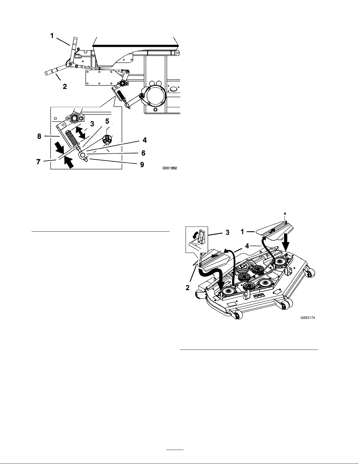
Figure 53
1. Brake lever-engaged
2. Brake lever-disengaged 8. Spring bracket
3. Spring, 2-3/4 inch (70 mm)
4. Jam nut above trunion
roller
5. Nut below spring bracket 11. Yoke
6. Trunion roller
7. 1/4-5/16 inch (5-8 mm)
9. Lock nut below trunion
10. Brake rod
4. R emo v e the tw o dri v e belts from the tw o upper
pulleys . R efer to R e placing the Dri v e Belts .
5. Pull on the spring loaded idler ar m to loosen
the belt tension.
6. R emo v e the mo w er belt from the mo w er
pulleys and the bottom pulley of the three
stac k ed pulleys ( Figure 54 and Figure 55 ).
7. Install the new belt around the mo w er pulleys
and the bottom pulley of the three stac k ed
pulleys ( Figure 54 and Figure 55 ).
8. Pull on the spring loaded idler ar m to loosen
the belt tension and align the mo w er belt onto
the idler pulley ( Figure 55 ).
9. Install the tw o dri v e belts onto the tw o upper
pulleys . R efer to R e placing the Dri v e Belts .
10. Install the belt co v ers with the tabs in the
slots . Install the screws and close the latc hes
( Figure 54 ).
roller
11. Chec k the tension on the dri v e belts . R efer to
Adjusting the Dri v e Belts .
Belt Maintenance
Inspecting the Belts
Inspect all belts daily .
Chec k belts for crac ks , fra yed edg es , bur n marks
or any other damag e . R e place damag ed belts .
Replacing the Mower Belt
Squealing when the belt is rotating, blades slipping
when cutting g rass , fra yed belt edg es , bur n marks
and crac ks are signs of a w or n mo w er belt. R e place
the mo w er belt if any of these conditions are
evident.
1. Diseng ag e the PTO , mo v e the motion control
lev ers to the neutral loc k ed position and set
the parking brak e .
2. Stop the engine , remo v e the k ey , and w ait for
all mo ving par ts to stop before lea ving the
operating position.
Figure 54
1. Belt cover
2. Latch 4. Install tab into the slot
3. Screw
3. R emo v e the screws and belt co v ers ( Figure 54 ).
46
Page 47
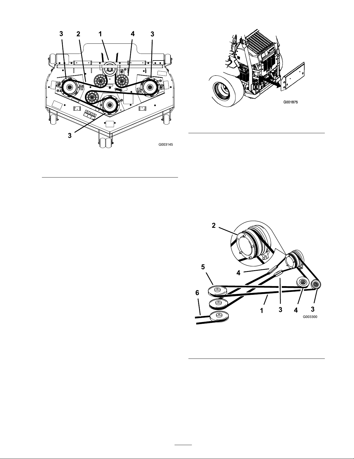
Figure 55
1. Three stack pulleys 3. Mower spindle pulley
2. Mower belt 4. Mower idler pulley
Replacing the Drive Belts
Figure 56
1. Rear engine panel
4. Pull on the spring loaded idler pulley to loosen
the belt tension ( Figure 57 ).
5. R emo v e the w or n dri v e belt.
6. Install the new dri v e belt around the clutc h
pulley , the adjustable idler pulleys , the spring
loaded idler pulley , and the front three stac k ed
pulleys ( Figure 57 ).
Squealing when the belt is rotating, blades slipping
when cutting g rass , fra yed belt edg es , bur n marks
and crac ks are signs of a w or n mo w er belt. R e place
the mo w er belt if any of these conditions are
evident.
Note: R emo v e the top dri v e belt first if the
bottom dri v e belt needs to be re placed.
1. Diseng ag e the PTO , mo v e the motion control
lev ers to the neutral loc k ed position and set
the parking brak e .
2. Stop the engine , remo v e the k ey , and w ait for
all mo ving par ts to stop before lea ving the
operating position.
3. R emo v e the rear engine panel ( Figure 56 ).
7. Adjust the belt tension; refer to Adjusting the
Dri v e Belts .
Figure 57
1. Drive belt 4. Adjustable idler pulley
2. Clutch 5. Three stacked pulleys
3. Spring loaded idler pulley 6. Mower belt
Adjusting the Drive Belts
Adjust the dri v e belts after the first 8 operating
hours and ev er y 50 hours there after .
1. Diseng ag e the PTO , mo v e the motion control
lev ers to the neutral loc k ed position and set
the parking brak e .
47
Page 48
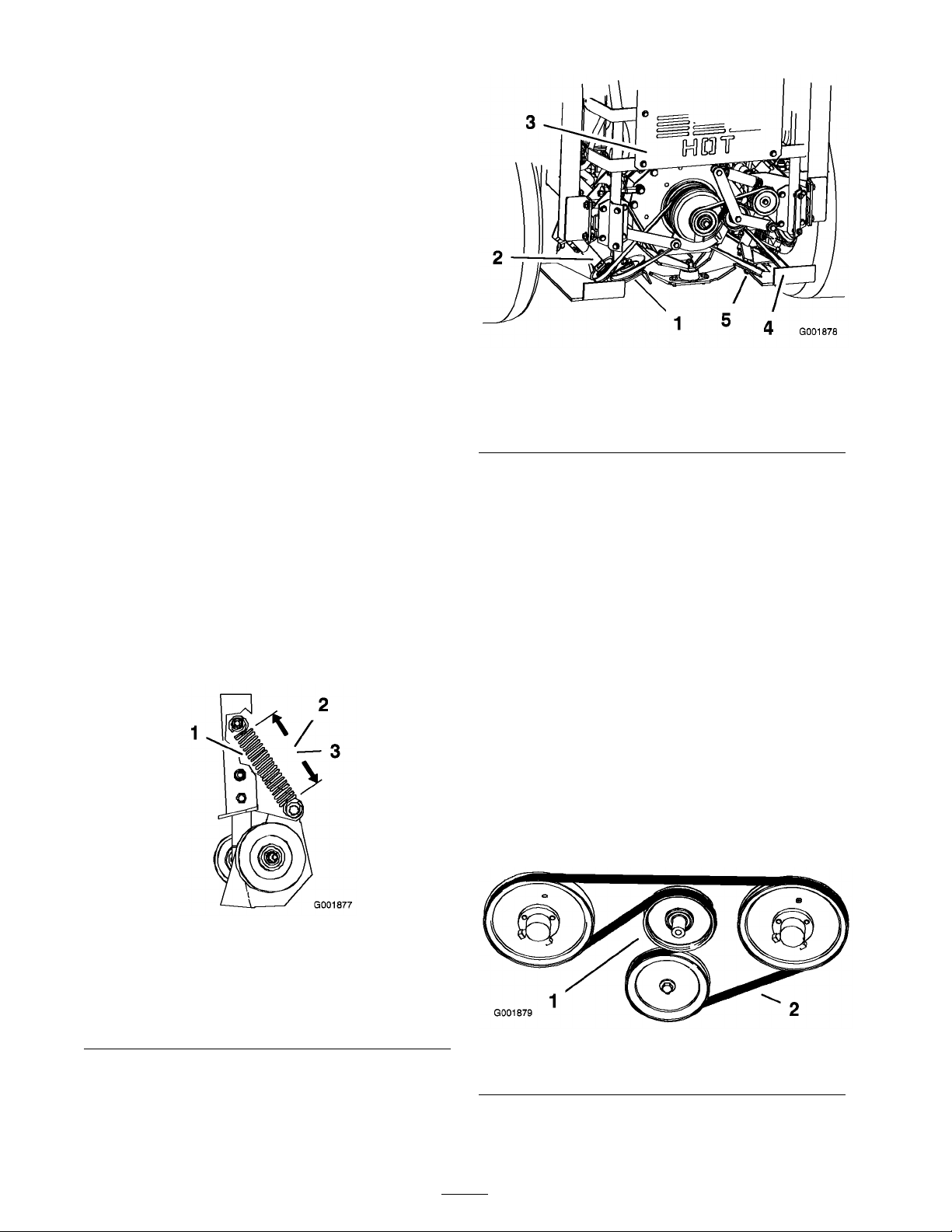
2. Stop the engine , remo v e the k ey , and w ait for
all mo ving par ts to stop before lea ving the
operating position.
Note: Measure only the spring coils .
3. Measure the length of the spring . Chec k
to mak e sure the coils of the spring on the
spring-loaded idler pulley measures as listed
belo w ( Figure 58 and Figure 59 ).
• Left spring measurement: 5-3/4 ± 1/8 inc h
(14.6 ± 0.3 cm) ( Figure 58 ).
• Right spring measurement: 5-1/2
± 1/8 inc h (14.0 ± 0.3 cm) ( Figure 58 ).
4. If the spring does not ha v e the cor rect
measurement, loosen the n ut holding the
adjustable idler pulley so it can mo v e up and
do wn in the slot ( Figure 59 ).
5. R eliev e the pressure on the spring-loaded idler
pulley ( Figure 59 ).
6. P osition the adjustable pulley lo w er in the slot
and tighten the n ut ( Figure 59 ).
7. Chec k to mak e sure the coils of the spring on
the spring-loaded idler pulley ha v e the cor rect
measurement ( Figure 58 ).
8. R e peat as necessar y on the opposite side of
the mac hine .
Figure 59
1. Left adjustable pulley 4. Right adjustable pulley
2. Left spring loaded idler
pulley
3. Back of the machine
5. Right spring loaded idler
pulley
Replacing the Pump Drive
Belt
Chec k pump dri v e belt for w ear after ev er y
50 hours of operation.
1. Tilt the seat forw ard and remo v e the front
engine panel.
2. Pull the spring loaded idler do wn and remo v e
the traction belt from the engine and h y dro
pump pulleys ( Figure 60 ). R emo v e the belt
betw een the pulleys .
Figure 58
1. Spring/Spring coils 3. Right spring
2. Left spring
measurement-5-3/4±
1/8 inch (14.6± 0.3 cm)
3. Install the new belt around the engine and
h y dro pump pulleys ( Figure 60 ).
4. Pull the spring loaded idler do wn and align it
belo w the traction belt. R elease the pressure
on the spring loaded idler ( Figure 60 ).
measurement-5-1/2 ±
1/8 inch (14.0± 0.3 cm)
Figure 60
1. Spring loaded idler pulley 2. Pump drive belt
48
Page 49
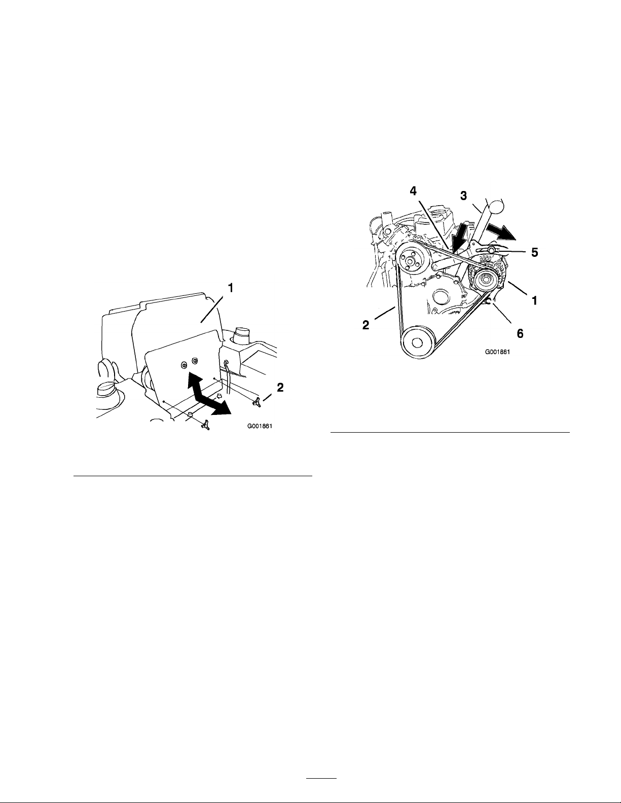
Replacing and Tensioning
the Alternator Belt
Chec k the alter nator belt for w ear after ev er y
50 hours of operation.
4. Chec k the deflection in the belt ag ain and
adjust the belt if needed.
5. If the deflection is cor rect, tor que the upper
bolt to 170 in-lb (19 N•m) and the bottom bolt
to 45 ft-lb (61 N•m) ( Figure 62 ).
Replacing the Alternator Belt
1. Diseng ag e the PTO , mo v e the motion control
lev ers to the neutral loc k ed position and set
the parking brak e .
2. Stop the engine , remo v e the k ey , and w ait for
all mo ving par ts to stop before lea ving the
operating position.
3. Tilt the seat forw ard and remo v e the front
engine panel ( Figure 61 ).
6. Install the pump dri v e belt; refer to R e placing
the Pump Dri v e Belt.
7. Install the front engine panel ( Figure 61 ).
Figure 62
1. Alternator 4. Deection, 3/8 to 1/2 inch
(10 to 13 mm)
2. Alternator belt 5. Top bolt
3. Handle 6. Bottom bolt
Figure 61
1. Front engine panel 2. Knob
4. R emo v e the pump dri v e belt. R efer to
R emo ving the Pump Dri v e Belt.
5. Loosen the tw o bolts holding the alter nator
( Figure 62 ).
6. R emo v e the belt from the pulleys and
alter nator ( Figure 62 ).
7. Install a new belt around the pulleys and the
alter nator ( Figure 62 ).
Tensioning the Alternator Belt
1. Place a handle betw een the alter nator and
cylinder bloc k ( Figure 62 ).
2. Adjust the alter nator to the outside until there
is 3/8 to 1/2 inc h (10 to 13 mm) deflections in
the belt betw een the engine and the alter nator
( Figure 62 ).
3. Tighten the alter nator bolts .
Controls System
Maintenance
Adjusting the Control
Handle Neutral Position
If motion control lev ers do not align, or mo v e
easily into the console notc h, adjustment is
required. Adjust eac h lev er , spring and rod
se parately .
Note: Motion control lev ers m ust be installed
cor rectly . See Installing the Motion Control Lev ers
in the set up instr uctions .
1. Diseng ag e the PTO , mo v e the motion control
lev ers to the neutral loc k ed position and set
the parking brak e .
2. Stop the engine , remo v e the k ey , and w ait for
all mo ving par ts to stop before lea ving the
operating position.
49
Page 50
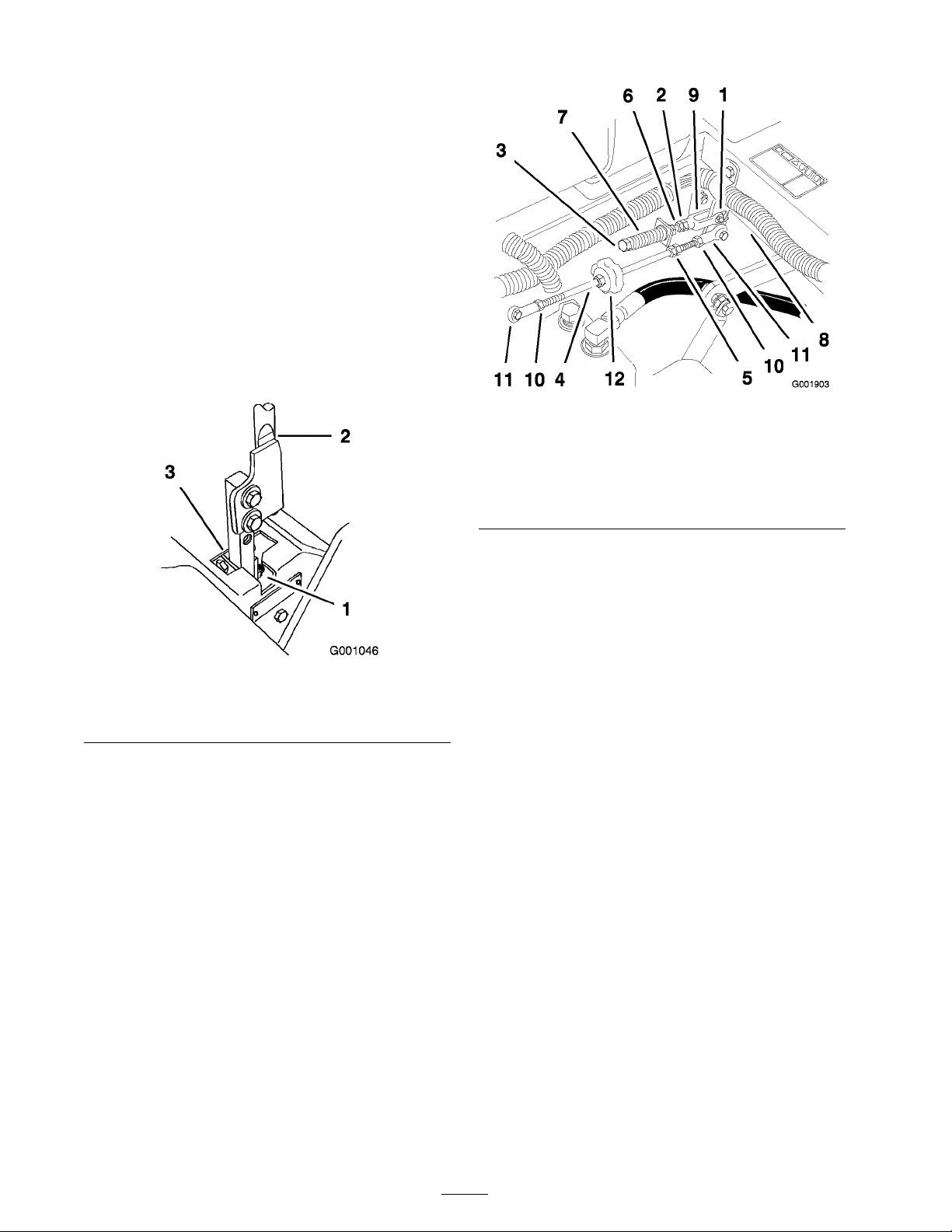
3. Unlatc h the seat and tilt the seat forw ard.
4. Begin with either the left or right motion
control lev er .
5. Mo v e the lev er to the neutral position but not
lock ed ( Figure 63 ).
6. Pull the lev er bac k until the clevis pin (on ar m
belo w pi v ot shaft) contacts the end of the slot
(just beginning to put pressure on the spring)
( Figure 63 ).
7. Chec k where the control lev er is relati v e to
notc h in console ( Figure 63 ). It should be
centered allo wing lev er to pi v ot outw ard to the
neutral loc k position.
Figure 64
1. Clevis pin in slot
2. Nut against yoke 8. Pivot shaft
3. Adjustment bolt 9. Yoke
4. Pump rod 10. Locknut
5. Double nuts 11. Ball joint
6. Jam Nut
7. Spring
12. Tracking knob
Figure 63
1. Neutral locked position 3. Neutral potion
2. Control lever
8. If adjustment is needed, loosen the n ut and
jam n ut ag ainst the y ok e ( Figure 64 ).
9. Apply slight rearw ard pressure on the motion
control lev er , tur n the head of the adjustment
bolt in the appropriate direction until the
control lev er is centered in the neutral loc k
position ( Figure 64 ).
Note: K ee ping rearw ard pressure on the
lev er will k ee p the pin at the end of the slot and
allo w the adjustment bolt to mo v e the lev er to
the appropriate position.
10. Tighten the n ut and jam n ut ( Figure 64 ).
11. R e peat for the opposite side of the mac hine .
Hydraulic System
Maintenance
Servicing the Hydraulic
System
Checking the Hydraulic Fluid
Fluid T ype: Mobil 1 15W -50 synthetic motor oil or
equi v alent synthetic oil.
Important: Use oil specified or equi v alent.
Other fluids could cause system dama ge.
Hy draulic System Oil Capacity: 132 ounces (3.9 l)
Chec k the h y draulic fluid lev el:
• Before the engine is first star ted.
• After the first 8 operating hours .
• After ev er y 25 operating hours .
Note: T here are tw o w a ys of c hec king the
h y draulic oil. One is when the oil is w ar m and one
is when the oil is cold. T he baffle inside the tank
has tw o lev els de pending if the oil is w ar m or cold.
1. P osition the mac hine on a lev el surface and set
the parking brak e .
50
Page 51
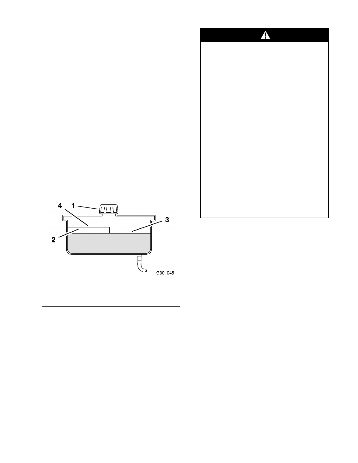
2. Clean the area around filler nec k of h y draulic
tank ( Figure 65 ).
3. R emo v e the cap from the filler nec k. Look
inside to c hec k if there is fluid in the reser v oir
( Figure 65 ).
4. If there is no fluid, add fluid to the reser v oir
until it reac hes the cold lev el of the baffle .
5. R un the mac hine at lo w idle for 15 min utes to
allo w any air to purg e out of the system and
w ar m the fluid. R efer to Star ting and Stopping
the Engine in Operation , pag e 17 .
6. R ec hec k the fluid lev el while the fluid is w ar m.
T he fluid should be betw een cold and hot.
7. If required, add fluid to the h y draulic tank.
Note: T he fluid lev el should be to the top
of the hot lev el of the baffle , when the fluid
is hot ( Figure 65 ).
8. Install cap on filler nec k.
Hy draulic fluid escaping under pr essur e
can penetrate skin and cause injur y .
• If h y draulic fluid is injected into the
skin it must be surgicall y r emo v ed
within a few hour s by a doctor f amiliar
with this type of injur y . Gang r ene
may r esult if this is not done.
• K eep body and hands a w ay fr om pin
hole leaks or nozzles that eject high
pr essur e h y draulic fluid.
• Use cardboard or paper to find
h y draulic leaks.
• Safel y r eliev e all pr essur e in the
h y draulic system bef or e perf or ming
an y w or k on the h y draulic system.
• Mak e sur e all h y draulic fluid hoses
and lines ar e in good condition and
all h y draulic connections and fittings
ar e tight bef or e appl ying pr essur e to
h y draulic system.
Figure 65
1. Cap
2. Bafe 4. Hot uid level-full
3. Cold uid level-full
Replacing the Hydraulic Filter and Oil
Chang e the h y draulic filter and oil:
• After the first 25 operating hours .
• Chang e yearly after the first 25 operating hours .
Use summer filter abo v e 32°F (0°C)
Use winter filter belo w 32°F (0°C)
1. Diseng ag e the PTO , mo v e the motion control
lev ers to the neutral loc k ed position and set
the parking brak e .
2. Stop the engine , remo v e the k ey , and w ait for
all mo ving par ts to stop before lea ving the
operating position.
Important: Do not substitute automoti v e
oil filter or sev er e h y draulic system dama ge
may r esult.
3. Place drain pan under filter , remo v e the old
filter and wipe the filter adapter g ask et surface
clean ( Figure 66 ).
51
Page 52
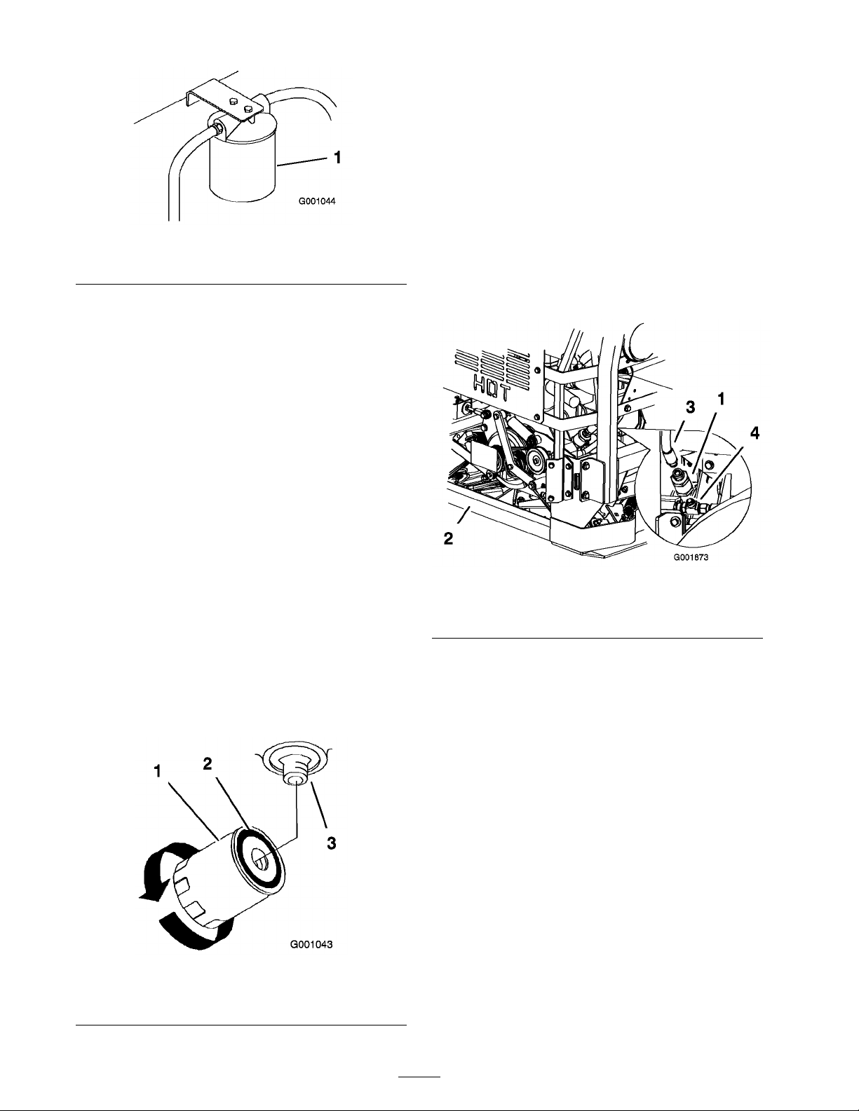
Figure 66
1. Hydraulic lter
4. Apply a thin coat to the r ubber g ask et on the
re placement filter ( Figure 67 ).
5. Install the re placement h y draulic filter onto the
filter adapter . Do not tighten.
6. Fill the h y draulic tank with h y draulic fluid until
the fluid o v erflo ws the filter and then tur n
the oil filter cloc kwise until the r ubber g ask et
contacts the filter adapter , then tighten the
filter an additional 1/2 tur n ( Figure 67 ).
Replacing the Cooling Fan Hydraulic
Filter
R e place the cooling fan h y draulic filter :
• After ev er y 500 operating hours .
• After any par t of the h y draulic cooling fan
system is re paired or re placed.
1. Place drain pan under filter , remo v e the
h y draulic hose from the filter ( Figure 68 ).
2. R emo v e the cooling fan h y draulic filter from
the T -fitting on the bottom of the filter
( Figure 68 ).
7. Clean up any spilled fluid.
8. Add fluid to the cold lev el of the baffle in the
h y draulic tank.
9. Star t the engine and let it r un for about tw o
min utes to purg e air from the system. Stop
the engine and c hec k for leaks . If one or
both wheels will not dri v e , refer to Bleeding
Hy draulic System.
10. R ec hec k the fluid lev el while the fluid is w ar m.
T he fluid should be betw een cold and hot.
11. If required, add fluid to the h y draulic tank. Do
not o v erfill.
Figure 68
1. Cooling fan hydraulic lter 3. Hydraulic hose
2. Back of machine 4. T-tting
3. Install the filter to the T -fitting on the bottom
and the h y draulic hose to the top ( Figure 68 ).
Bleeding the Hydraulic System
T he traction system is self bleeding, ho w ev er , it
ma y be necessar y to bleed the system if fluid is
c hang ed or after w ork is perfor med on the system.
1. Raise rear of the mac hine so wheels are off the
g round and suppor t with jac k stands .
2. Star t the engine and r un at lo w idle speed.
Eng ag e the lev er and traction on one side and
spin the wheel b y hand.
Figure 67
1. Hydraulic lter 3. Adapter
2. Gasket
3. W hen the wheel begins to spin on its o wn,
k ee p it eng ag ed until wheel dri v es smoothly .
(minim um 2 min utes)
4. Chec k h y draulic fluid lev el and add as required
to maintain proper lev el.
5. R e peat this procedure on the opposite wheel.
52
Page 53

Checking the Hydraulic Hoses
After ev er y 100 operating hours , c hec k the
h y draulic hoses for leaks , loose fittings , kink ed
lines , loose mounting suppor ts , w ear , w eather and
c hemical deterioration. Mak e necessar y re pairs
before operating .
Note: K ee p areas around the h y draulic system
clean from g rass and debris build up .
Hy draulic fluid escaping under pr essur e can
penetrate skin and cause injur y .
• If h y draulic fluid is injected into the skin
it must be surgicall y r emo v ed within a
few hour s by a doctor f amiliar with this
type of injur y . Gang r ene may r esult if
this is not done.
• K eep body and hands a w ay fr om pin hole
leaks or nozzles that eject high pr essur e
h y draulic fluid.
• Use cardboard or paper to find h y draulic
leaks.
• Safel y r eliev e all pr essur e in the h y draulic
system bef or e perf or ming an y w or k on
the h y draulic system.
• Mak e sur e all h y draulic fluid hoses
and lines ar e in good condition and
all h y draulic connections and fittings
ar e tight bef or e appl ying pr essur e to
h y draulic system.
Setting the Hydraulic Pump
Neutral Position
Note: Adjust the handle neutral first. T hat needs
to be cor rect before the follo wing adjustment can
be made .
T his adjustment m ust be made with dri v e wheels
tur ning .
Mechanical or h y draulic jacks may f ail to
suppor t machine and cause a serious injur y .
• Use jack stand when suppor ting
machine.
• Do not use h y draulic jacks.
Engine must be r unning so motion contr ol
adjustment can be perf or med. Contact with
mo ving par ts or hot surf aces may cause
per sonal injur y .
K eep hands, feet, f ace, clothing and other
body par ts a w ay fr om r otating par ts, muf fler
and other hot surf aces.
1. Raise the frame and bloc k up the mac hine so
dri v e wheels can rotate freely .
2. Disconnect the electrical connector from the
seat safety switc h. T emporarily install a jumper
wire across ter minals in the wiring har ness
connector .
3. Unlatc h the seat and slide seat forw ard.
4. Disconnect the seat rod and tilt the seat fully
forw ard.
Setting the Left-hand Hydraulic Pump
Neutral Position
1. Star t the engine , open the throttle 1/2 w a y and
release parking brak e . R efer to Star ting and
Stopping the Engine in Operation , pag e 17 .
Note: T he motion control lev er m ust be in
neutral while making any adjustments .
2. Adjust the pump rod length b y rotating the
knob , in the appropriate direction, until the
wheel is still or slightly cree ping in rev erse
( Figure 69 ).
53
Page 54
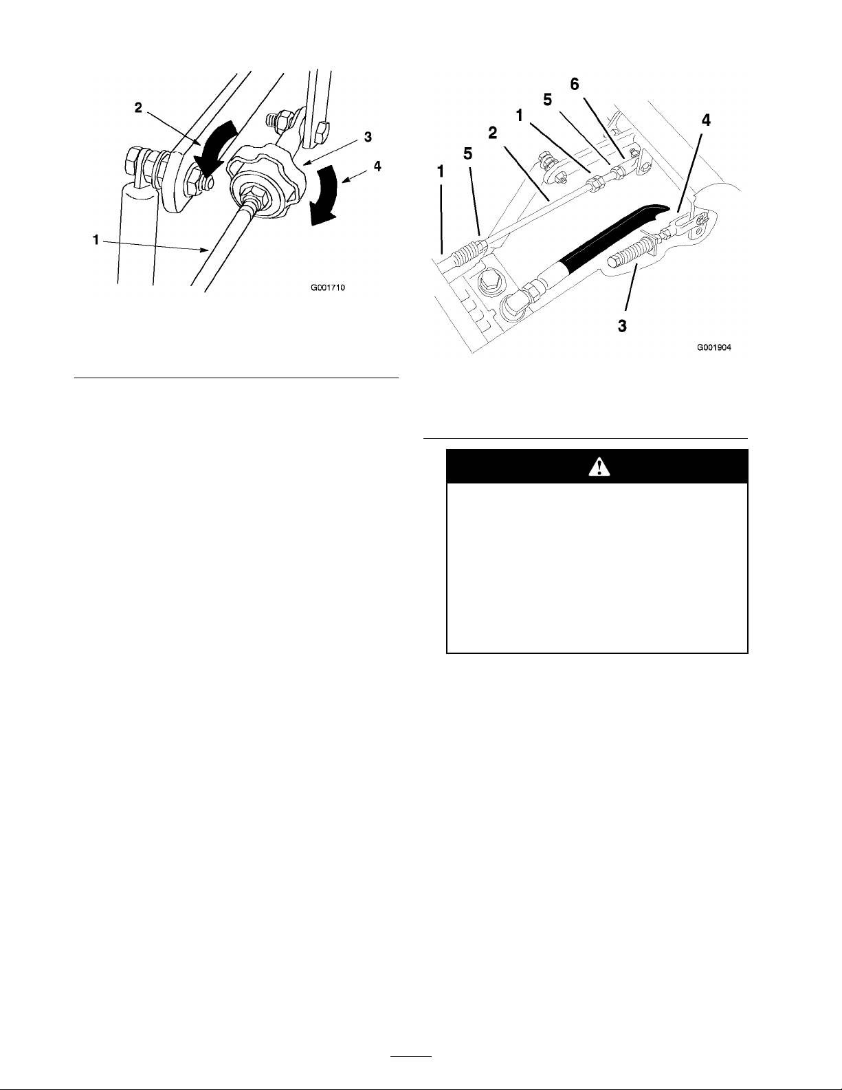
Figure 69
1. Tracking knob 4. Turn this way to track right
2. Hydraulic tank 5. Turn this way to track left
3. Hydraulic pumps
3. Mo v e the motion control lev er forw ard and
rev erse , then bac k to neutral. T he wheel m ust
stop tur ning or slightly cree p in rev erse .
4. Open the throttle to fast. Mak e sure wheel
remains stopped or slightly cree ps in rev erse ,
adjust if necessar y .
Setting the Right-hand Hydraulic
Pump Neutral Position
1. Loosen the loc kn uts at the ball joints on the
pump control rod ( Figure 70 ).
Figure 70
1. Double nuts 4. Locknut
2. Pump rod 5. Ball joint
3. Adjustment bolt
6. Pumps
Electrical system will not perf or m pr oper
safety shut of f with jumper wir e installed.
• R emo v e jumper wir e fr om wir e
har ness connector and plug
connector into seat s witch when
adjustment is completed.
2. Star t the engine , open throttle 1/2 w a y and
release parking brak e . R efer to Star ting and
Stopping the Engine in Operation , pag e 17 .
Note: T he motion control lev er m ust be in
neutral while making any adjustments .
Note: T he front n ut on the pump rod has
left-hand threads .
3. Adjust the pump rod length b y rotating double
n uts on rod, in the appropriate direction,
until wheel is still or slightly cree ps in rev erse
( Figure 70 ).
4. Mo v e the motion control lev er forw ard and
rev erse , then bac k to neutral. T he wheel m ust
stop tur ning or slightly cree p in rev erse .
5. Open the throttle to fast. Mak e sure the wheel
remains stopped or slightly cree ps in rev erse ,
adjust if necessar y .
6. Tighten the loc kn uts at the ball joints
( Figure 70 ).
• Nev er operate this unit with jumper
installed and seat s witch bypassed.
7. After both pump neutrals are set, shut off the
mac hine .
8. R emo v e the jumper wire from the wire har ness
connector and plug the connector into the seat
switc h.
9. Install the seat rod and lo w er the seat into
position.
10. R emo v e the jac k stands .
Mower Deck
Maintenance
Leveling the Mower at Three
Positions
Important: T her e ar e onl y thr ee measuring
positions needed to lev el the mo w er .
54
Page 55
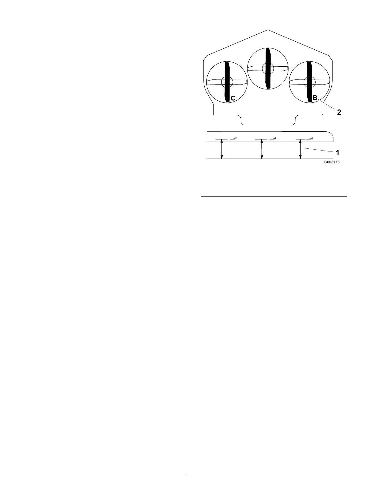
Setting Up the Machine
1. P osition the mo w er on a flat surface .
2. Diseng ag e the PTO , mo v e the motion control
lev ers to the neutral loc k ed position and set
the parking brak e .
3. Stop the engine , remo v e the k ey , and w ait for
all mo ving par ts to stop before lea ving the
operating position.
4. Chec k tire pressure of all four tires . If needed,
adjust to 13 psi (90 kP a)
5. Lo w er the mo w er to the 3 inc h (76 mm)
height-of-cut position.
6. Inspect the four c hains . T he c hains need to
ha v e tension.
• If one rear c hain is loose , lo w er (loosen) the
front suppor t ar m on the same side . R efer to
Adjusting the F ront-to-R ear Mo w er Pitc h.
1. Measure here from blade
to hard surface
Figure 71
2. Measure at B and C
• If one front c hain is loose , raise (tighten) the
front suppor t ar m for that c hain. R efer to
Adjusting the F ront-to-R ear Mo w er Pitc h.
Leveling the Mower Side-to-Side
1. P osition the right blade front-to-rear
( Figure 71 ).
2. Measure the right blade at the B location, from
a lev el surface to the cutting edg e of the blade
tip ( Figure 71 ).
3. R ecord this measurement. T his measurement
needs to be 3-1/8 to 3-1/4 inc hes .
4. P osition the left blade front-to-rear ( Figure 71 ).
5. Measure the left blade at the C location
( Figure 71 ), from a lev el surface to the cutting
edg e of the blade tip .
6. R ecord this measurement. T his measurement
needs to be 3-1/8 to 3-1/4 inc hes .
7. If the measurements at positions B or C are
not cor rect, loosen the bolt attac hing the rear
c hain to the rear suppor t ar m ( Figure 72 ).
8. Loosen the jam n ut under the rear suppor t
ar m and adjust the adjustment bolt to g et
a measurement of 3-1/8 to 3-1/4 inc hes
( Figure 72 ).
Note: It is recommended that both sides of
the mo w er are adjusted the same distance .
9. Tighten the jam n ut under the rear suppor t
ar m and tighten the bolt securing the c hain to
the rear suppor t ar m.
10. Adjust the opposite side if needed.
55
Page 56
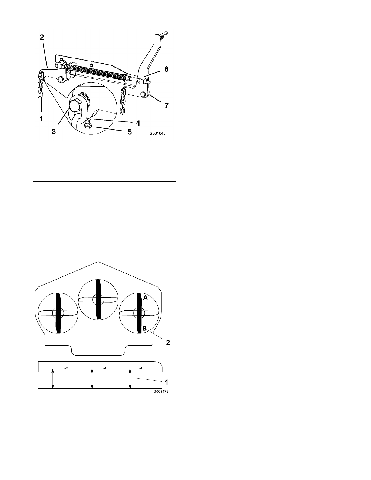
Figure 72
1. Rear chain 5. Adjustment bolt
2. Rear support arm
3. Bolt
4. Jam Nut
6. Front swivel
7. Front support arm
Adjusting the Front-to-Rear Mower
Pitch
1. P osition the right blade front-to-rear
( Figure 73 ).
2. Measure the right blade at the A location, from
a lev el surface to the cutting edg e of the blade
tip ( Figure 73 ).
4. Measure the right blade at the B location, from
a lev el surface to the cutting edg e of the blade
tip ( Figure 73 ).
5. R ecord this measurement.
6. T he mo w er blade should be a 1/4 to 3/8 inc h
(6 to 10 mm) lo w er at position A than at
position B ( Figure 73 ). If it is not cor rect,
proceed to the follo wing ste ps .
Note: Both of the front swi v els need to be
adjusted the same amount to maintain equal
c hain tension.
7. Loosen the front swi v el jam n uts , at the front
of the right and left swi v els , appro ximately a
1/2 inc h (13 mm) ( Figure 72 ).
8. Adjust the lift n uts on both the left and the
right side of the mac hine to ac hiev e 1/4 to
3/8 inc h (6 to 10 mm) lo w er in front at A than
in the rear at B ( Figure 72 ).
9. Tighten both swi v el jam n uts ag ainst the front
swi v el to loc k the height.
10. Chec k to mak e sure there is equal tension on
the c hains and adjust ag ain if needed.
Adjusting the Compression Spring
1. Raise the mo w er lift lev er to the transpor t
position.
1. Measure here from blade
to hard surface
3. R ecord this measurement.
2. Chec k the distance betw een the tw o larg e
w ashers , it needs to be 11-1/2 inc hes (29.2 cm)
( Figure 74 ).
3. Adjust this distance , b y loosening the spring
jam n ut and tur ning the n ut in front of eac h
spring ( Figure 74 ). T ur ning the n ut cloc kwise
will shor ten the spring; counter -cloc kwise will
lengthen the spring .
4. Loc k the n ut into position b y tightening the
spring jam n ut ( Figure 74 ).
Figure 73
2. Measure at A and B
56
Page 57
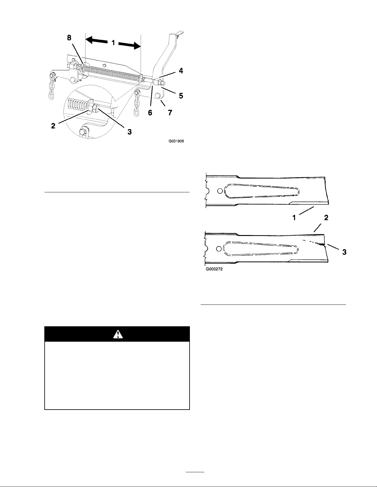
Figure 74
1. 11–1/2 inch (29.2 cm)
between the large washers
2. Front nut
3. Spring jam nut
4. Front swivel 8. Large washer
Servicing the Cutting Blades
5. Swivel jam nut
6. Lift nut
7. Front support arm
Before Inspecting or Servicing the
Blades
P ark the mac hine on a lev el surface , diseng ag e the
blade control (PTO), and set the parking brak e .
T ur n the ignition k ey to Off . R emo v e the k ey .
Inspecting the Blades
1. Inspect the cutting edg es ( Figure 75 ). If the
edg es are not shar p or ha v e nic ks , remo v e and
shar pen the blades . R efer to Shar pening the
Blades .
2. Inspect the blades , especially the cur v ed area
( Figure 75 ). If y ou notice any damag e , w ear ,
or a slot for ming in this area ( Figure 75 ),
immediately install a new blade .
Maintain shar p blades throughout the cutting
season because shar p blades cut cleanly without
tearing or shredding the g rass blades . T earing and
shredding tur ns g rass bro wn at the edg es , whic h
slo ws g ro wth and increases the c hance of disease .
Chec k the cutter blades daily for shar pness , and
for any w ear or damag e . File do wn any nic ks
and shar pen the blades as necessar y . If a blade is
damag ed or w or n, re place it immediately with a
g en uine T oro re placement blade . F or con v enient
shar pening and re placement, y ou ma y w ant to
k ee p extra blades on hand.
A w or n or dama ged blade can br eak, and a
piece of the blade could be thr o wn into the
operator’ s or bystander’ s ar ea, r esulting in
serious per sonal injur y or death.
• Inspect the blade periodicall y f or w ear
or dama ge.
• R eplace a w or n or dama ged blade.
Inspect and c hec k the blades ev er y 8 hours .
Figure 75
1. Cutting Edge 3. Wear/slot Forming
2. Curved Area
Checking for Bent Blades
1. Diseng ag e the PTO , mo v e the motion control
lev ers to the neutral loc k ed position and set
the parking brak e .
2. Stop the engine , remo v e the k ey , and w ait for
all mo ving par ts to stop before lea ving the
operating position.
3. R otate the blades until the ends face forw ard
and bac kw ard ( Figure 76 ). Measure from a
lev el surface to the cutting edg e , position A , of
the blades ( Figure 76 ). Note this dimension.
57
Page 58
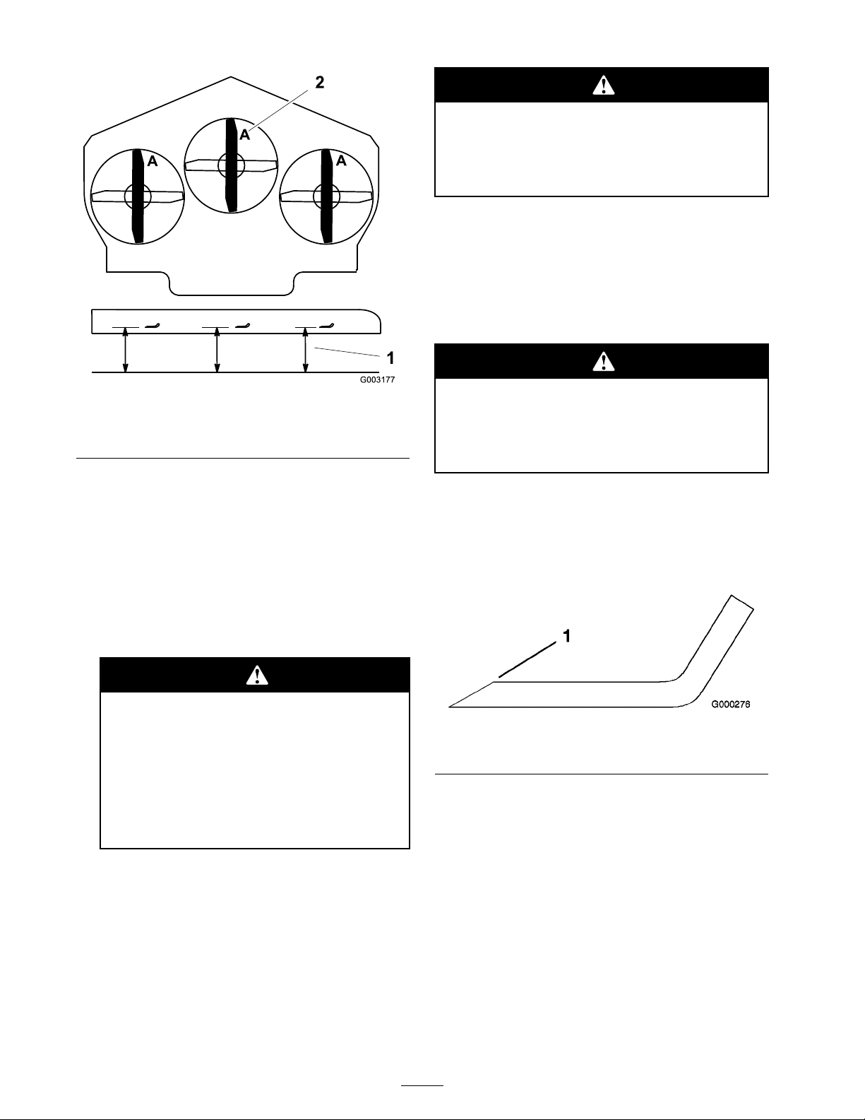
Contact with a shar p blade can cause serious
injur y .
W ear g lo v es or wrap shar p edges of the
blade with a ra g .
1. Hold the blade end using a rag or
thic kly-padded glo v e .
2. R emo v e the blade bolt, spring disk and blade
from the spindle shaft ( Figure 79 ).
Sharpening the Blades
Figure 76
1. Measure here from blade
to hard surface
2. Position A
4. R otate the opposite ends of the blades forw ard.
5. Measure from a lev el surface to the cutting
edg e of the blades at the same position as
in ste p 3 abo v e . T he difference betw een the
dimensions obtained in ste ps 3 and 4 m ust not
ex ceed 1/8 inc h (3 mm). If this dimension
ex ceeds 1/8 inc h (3 mm), the blade is bent
and m ust be re placed; refer to R emo ving the
Blades and Installing the Blades .
A blade that is bent or dama ged could
br eak apar t and could seriousl y injur e or
kill y ou or bystander s.
• Al w ays r eplace bent or dama ged
blade with a new blade.
• Nev er file or cr eate shar p notches in
the edges or surf aces of blade.
Removing the Blades
Blades m ust be re placed if a solid object is hit,
if the blade is out of balance or is bent. T o
ensure optim um perfor mance and contin ued
safety confor mance of the mac hine , use g en uine
TOR O re placement blades . R e placement blades
made b y other man ufacturers ma y result in
non-confor mance with safety standards .
W hen shar pening blade, pieces of blade
could be thr o wn and cause serious injur y .
W ear pr oper ey e pr otection when shar pening
blade.
1. Use a file to shar pen the cutting edg e at both
ends of the blade ( Figure 77 ). Maintain the
original angle . T he blade retains its balance if
the same amount of material is remo v ed from
both cutting edg es .
Figure 77
1. Sharpen at original angle
2. Chec k the balance of the blade b y putting it on
a blade balancer ( Figure 78 ). If the blade sta ys
in a horizontal position, the blade is balanced
and can be used. If the blade is not balanced,
file some metal off the end of the sail area only
( Figure 79 ). R e peat this procedure until the
blade is balanced.
58
Page 59
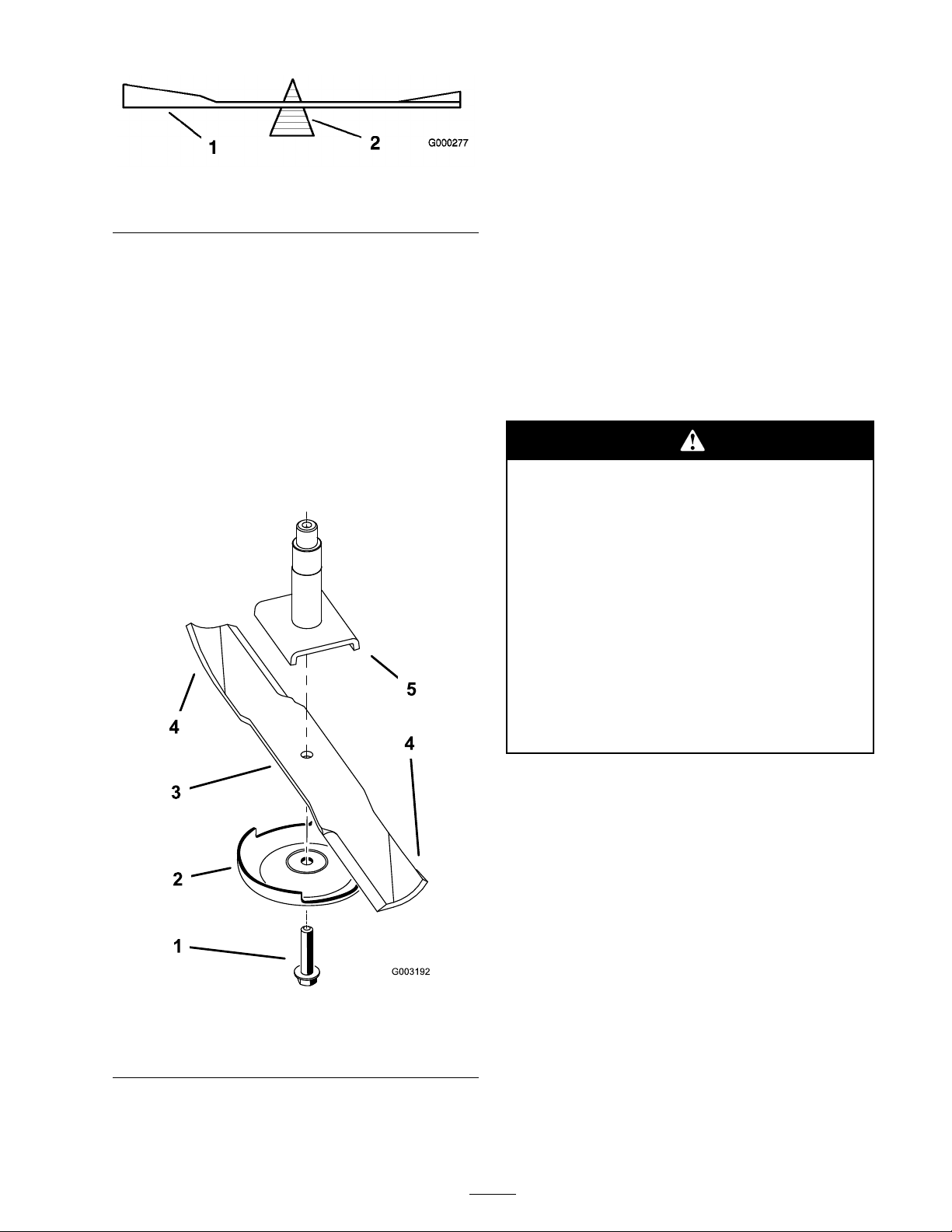
Cleaning
Cleaning Under the Mower
Figure 78
1. Blade 2. Balancer
Installing the Blades
1. Install the blade onto the spindle shaft
( Figure 79 ).
Important: T he cur v ed par t of the blade
must be pointing up w ard to w ard the inside
of the mo w er to ensur e pr oper cutting .
2. Install the spring disk and blade bolt. T he
spring disk cone m ust be installed to w ard the
bolt head ( Figure 79 ). T or que the blade bolt to
85-110 ft-lb (115-150 N•m).
R emo v e the g rass buildup under the mo w er daily .
1. Diseng ag e the PTO , mo v e the motion control
lev ers to the neutral loc k ed position and set
the parking brak e .
2. Stop the engine , remo v e the k ey , and w ait for
all mo ving par ts to stop before lea ving the
operating position.
3. Raise the mo w er to the transpor t position.
4. Raise the front of the mac hine b y using the Z
Stand®.
T he machine could f all onto someone and
cause serious injur y or death.
• Use extr eme caution when operating the
machine on the Z Stand®.
• Use onl y f or cleaning the mo w er and
r emo ving the blades.
• Do not k eep the machine on the Z
Stand® f or extended periods of time.
Figure 79
1. Blade Bolt 4. Sail Area of Blade
2. Anti-scalp plate 5. Spindle
3. Blade
• Al w ays tur n the engine of f, set the
par king brak e, and r emo v e the k ey
bef or e perf or ming an y maintenance to
the mo w er .
Waste Disposal
Engine oil, batteries , h y draulic oil, and engine
coolant are pollutants to the en vironment.
Dispose of these according to y our state and local
regulations .
59
Page 60

Storage
Cleaning and Storage
1. Diseng ag e the po w er tak e off (PTO), set the
parking brak e , and tur n the ignition k ey to Off .
R emo v e the k ey .
2. R emo v e g rass clippings , dir t, and g rime from
the exter nal par ts of the entire mac hine ,
especially the engine and h y draulic system.
Clean dir t and c haff from the outside of the
engine cylinder head fins and blo w er housing .
Important: Y ou can w ash the machine
with mild detergent and w ater . Do
not pr essur e w ash the machine. A v oid
ex cessi v e use of w ater , especiall y near the
contr ol panel, engine, h y draulic pumps,
and motor s.
3. Chec k the brak e; refer to Ser vicing the Brak e
in Brak e Maintenance , pag e 45 .
4. Ser vice the air cleaner; refer to Ser vicing the
Air Cleaner in Engine Maintenance , pag e 35 .
5. Grease the mac hine; refer to Greasing and
Lubrication in Lubrication , pag e 34 .
6. Chang e the crankcase oil; refer to Ser vicing the
Engine Oil in Engine Maintenance , pag e 35 .
7. Chec k the tire pressure; refer to Chec king the
Tire Pressure in Dri v e System Maintenance ,
pag e 42 .
8. Chang e the h y draulic filter; refer to
Ser vicing the Hy draulic System in
Hy draulic System Maintenance , pag e 50 .
A. Add a petroleum based
stabilizer/conditioner to fuel in the
tank. F ollo w mixing instr uctions from
the stabilizer man ufacturer . Do not use
an alcohol based stabilizer (ethanol or
methanol).
Note: A fuel stabilizer/conditioner is
most effecti v e when mix ed with fresh fuel
and used at all times .
B . R un the engine to distribute conditioned
fuel through the fuel system (5 min utes).
C . Stop the engine , allo w it to cool, and drain
the fuel tank; refer to Ser vicing the Fuel
T ank in Fuel System Maintenance , pag e 39 .
D . R estar t the engine and r un it until it stops .
E. Dispose of fuel properly . R ecycle as per
local codes .
Important: Do not stor e
sta biliz er/conditioned fuel o v er
90 days.
13. Chec k and tighten all bolts , n uts , and screws .
R e pair or re place any par t that is damag ed.
14. P aint all scratc hed or bare metal surfaces . P aint
is a v ailable from y our A uthorized Ser vice
Dealer .
15. Store the mac hine in a clean, dr y g arag e or
storag e area. R emo v e the k ey from the ignition
switc h and k ee p it out of reac h of c hildren or
other unauthorized users . Co v er the mac hine
to protect it and k ee p it clean.
9. Charg e the batter y; refer to Ser vicing the
Batter y in Electrical System Maintenance ,
pag e 40 .
10. Scrape any hea vy buildup of g rass and dir t
from the underside of the mo w er , then w ash
the mo w er with a g arden hose .
Note: R un the mac hine with the PTO
eng ag ed and the engine at high idle for 2 to
5 min utes after w ashing .
11. Chec k the condition of the blades;
refer to Ser vicing the Cutting Blades in
Mo w er Dec k Maintenance , pag e 54 .
12. Pre pare the mac hine for storag e when non-use
occurs o v er 30 da ys . Pre pare the mac hine for
storag e as follo ws:
60
Page 61

Troubleshooting
Problem
Starter does not crank
Engine will not start, starts
hard, or fails to keep
running.
Possible Cause Corrective Action
1. Blade control (PTO) is
engaged.
2. Parking brake is not on. 2. Set the parking brake.
3. Operator is not seated. 3. Sit on the seat.
4. Battery is dead. 4. Charge the battery.
5. Electrical connections
are corroded or loose.
6. Fuse is blown. 6. Replace the fuse.
7. Relay or switch is
defective.
1. Fuel tank is empty. 1. Fill the fuel tank with
2. Air cleaner is dirty. 2. Clean or replace the air
3. Dirt in the fuel lter. 3. Replace the fuel lter.
4. Dirt, water, or stale fuel
is in the fuel system.
1. Move the blade contro
(PTO) to disengaged.
5. Check the electrical
connections for good
contact.
7. Contact an Authorized
Service Dealer.
fuel.
cleaner element.
4. Contact an Authorized
Service Dealer.
Engine loses power.
Engine overheats.
1. Engine load is excessive. 1. Reduce the ground
speed.
2. Air cleaner is dirty. 2. Clean the air cleaner
element.
3. Oil level in the crankcase
is low.
4. Cooling ns and air
passages above the
engine are plugged.
5. Vent hole in the fuel cap
is plugged.
6. Dirt in the fuel lter. 6. Replace the fuel lter.
7. Dirt, water, or stale fuel
is in the fuel system.
1. Engine load is excessive. 1. Reduce the ground
2. Oil level in the crankcase
is low.
3. Cooling ns and air
passages above the
engine are plugged.
3. Add oil to the crankcase.
4. Remove the obstruction
from the cooling ns and
air passages.
5. Clean or replace the fuel
cap.
7. Contact an Authorized
Service Dealer.
speed.
2. Add oil to the crankcase.
3. Remove the obstruction
from the cooling ns and
air passages.
61
Page 62

Problem
Possible Cause Corrective Action
Machine does not drive.
Abnormal vibration.
1. By pass valve is not
1. Tighten the by pass
closed tight.
2. Drive or pump belt is
2. Change the belt.
worn, loose or broken.
3. Drive or pump belt is off
3. Change the belt.
a pulley.
4. Broken or missing idler
4. Replace the spring.
spring.
5. Hydraulic uid level is
5. Add hydraulic uid to
low or too hot.
1. Cutting blade(s) is/are
1. Install new cutting
bent or unbalanced.
2. Blade mounting bolt is
2. Tighten the blade
loose.
3. Engine mounting bolts
3. Tighten the engine
are loose.
4. Loose engine pulley,
4. Tighten the appropriate
idler pulley, or blade
pulley.
5. Engine pulley is
5. Contact an Authorized
damaged.
6. Blade spindle is bent. 6. Contact an Authorized
7. Motor mount is loose or
7. Contact an Authorized
worn.
valve.
the reservoir or let it cool
down.
blade(s).
mounting bolt.
mounting bolts.
pulley.
Service Dealer.
Service Dealer.
Service Dealer.
Uneven cutting height.
1. Blade(s) not sharp. 1. Sharpen the blade(s).
2. Cutting blade(s) is/are
bent.
2. Install new cutting
blade(s).
3. Mower is not level. 3. Level the mower
from side-to-side and
front-to-rear.
4. Underside of mower is
dirty.
5. Tire pressure is not
4. Clean the underside of
the mower.
5. Adjust the tire pressure.
correct.
6. Blade spindle bent. 6. Contact an Authorized
Service Dealer.
62
Page 63

Problem
Possible Cause Corrective Action
Blades do not rotate.
1. Drive belt is worn, loose
1. Check the belt tension.
or broken.
2. Drive belt is off pulley. 2. Install the drive belt
and check adjusting
shafts and belt guides for
correct position.
3. Deck belt is worn, loose
3. Install a new deck belt.
or broken.
4. Deck belt is off pulley. 4. Install the deck pulley
and check the idler
pulley, idler arm and
spring for correct
position and function.
5. Broken or missing idler
5. Replace the spring.
spring.
63
Page 64
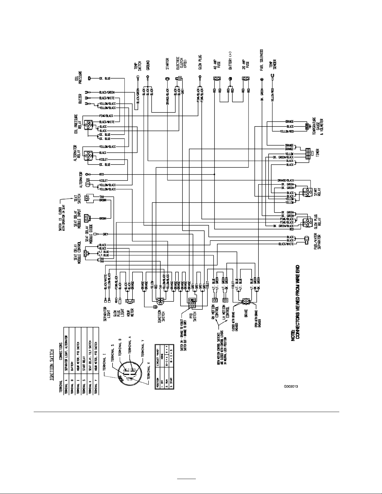
Schematics
Wire Diagram (Rev. A)
64
 Loading...