

FormNo.3424-708RevC
ZMaster
®
Professional7000
SeriesRidingMower
With132cmor152cmTURBOFORCE
Mower
ModelNo.74264TE—SerialNo.403138013andUp
ModelNo.74265TE—SerialNo.403227065andUp
ModelNo.74279TE—SerialNo.403320852andUp
®
Registeratwww.T oro.com.
OriginalInstructions(EN)
*3424-708*
GrossorNetTorque:Thisproductcomplieswith
allrelevantEuropeandirectives;fordetails,please
seetheseparateproductspecicDeclarationof
Conformity(DOC)sheet.Thegrossornettorque
ofthisenginewaslaboratoryratedbytheengine
manufacturerinaccordancewiththeSocietyof
AutomotiveEngineers(SAE)J1940orJ2723.As
conguredtomeetsafety,emission,andoperating
requirements,theactualenginetorqueonthisclass
ofmowerwillbesignicantlylower.Pleasereferto
theenginemanufacturer’sinformationincludedwith
themachine.
Pleaserefertotheenginemanufacturer’sinformation
includedwiththemachine.
WARNING
CALIFORNIA
Proposition65Warning
Dieselengineexhaustandsomeofits
constituentsareknowntotheStateof
Californiatocausecancer,birthdefects,
andotherreproductiveharm.
Batteryposts,terminals,andrelated
accessoriescontainleadandlead
compounds,chemicalsknownto
theStateofCaliforniatocause
cancerandreproductiveharm.Wash
handsafterhandling.
FortheOperator’sManual,thecompletewarranty
details,ortoregisteryourproduct,usetheQR
codeorvisitwww.Toro.com.Youmayalsocallus
at1-888-384-9939torequestawrittencopyofthe
productwarranty.
Wheneveryouneedservice,genuineToroparts,or
additionalinformation,contactanAuthorizedService
DealerorToroCustomerServiceandhavethemodel
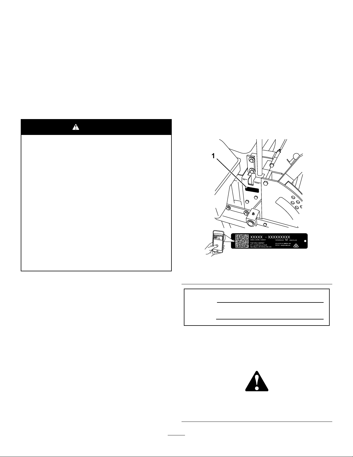
andserialnumbersofyourproductready.Figure1
identiesthelocationofthemodelandserialnumbers
ontheproduct.Writethenumbersinthespace
provided.
Important:Withyourmobiledevice,youcan
scantheQRcode(ifequipped)ontheserial
numberdecaltoaccesswarranty,parts,andother
productinformation.
Useofthisproductmaycauseexposure
tochemicalsknowntotheStateof
Californiatocausecancer,birthdefects,
orotherreproductiveharm.
Introduction
Thisrotary-blade,ridinglawnmowerisintendedtobe
usedbyprofessional,hiredoperators.Itisdesigned
primarilyforcuttinggrassonwell-maintainedlawnson
residentialorcommercialproperties.Itisnotdesigned
forcuttingbrushorforagriculturaluses.
Readthisinformationcarefullytolearnhowtooperate
andmaintainyourproductproperlyandtoavoid
injuryandproductdamage.Youareresponsiblefor
operatingtheproductproperlyandsafely.
YoumaycontactT orodirectlyatwww.T oro.com
forproductsafetyandoperationtrainingmaterials,
accessoryinformation,helpndingadealer,orto
registeryourproduct.
g248729
Figure1
1.Modelandserialnumberlocation
ModelNo.
SerialNo.
Thismanualidentiespotentialhazardsandhas
safetymessagesidentiedbythesafety-alertsymbol
(Figure2),whichsignalsahazardthatmaycause
seriousinjuryordeathifyoudonotfollowthe
recommendedprecautions.
g000502
Figure2
Safety-alertsymbol
©2022—TheToro®Company
8111LyndaleAvenueSouth
Bloomington,MN55420
Contactusatwww.Toro.com.
2
PrintedintheUSA
AllRightsReserved

Thismanualuses2wordstohighlightinformation.
Importantcallsattentiontospecialmechanical
informationandNoteemphasizesgeneralinformation
worthyofspecialattention.
Contents
Safety.......................................................................4
GeneralSafety...................................................4
SlopeIndicator...................................................5
SafetyandInstructionalDecals..........................6
ProductOverview...................................................16
Controls...........................................................16
BeforeOperation.................................................18
BeforeOperationSafety...................................18
PerformingDailyMaintenance..........................18
AddingFuel......................................................18
BreakinginaNewMachine..............................20
UsingtheRollover-ProtectionSystem
(ROPS).........................................................20
UsingtheSafety-InterlockSystem....................21
PositioningtheSeat..........................................22
UnlatchingtheSeat..........................................22
ChangingtheSeatSuspension.........................22
DuringOperation.................................................23
DuringOperationSafety...................................23
OperatingtheParkingBrake.............................25
OperatingtheMowerBlade-ControlSwitch
(PTO)............................................................25
OperatingtheThrottle.......................................25
StartingandShuttingOfftheEngine.................26
UsingtheMotion-ControlLevers.......................27
DrivingtheMachine..........................................27
UsingtheSideDischarge.................................29
AdjustingtheHeightofCut...............................29
AdjustingtheAnti-ScalpRollers........................30
AdjustingtheAnti-ScalpRollers........................31
AdjustingtheFlowBafeCamLocks................32
PositioningtheFlowBafe................................32
OperatingwiththeOverheatSensor.................33
OperatingTips.................................................33
AfterOperation....................................................34
AfterOperationSafety......................................34
UsingtheFuel-ShutoffValve.............................34
PushingtheMachinebyHand..........................35
TransportingtheMachine.................................35
UsingtheZStand
Maintenance...........................................................39
RecommendedMaintenanceSchedule(s)...........39
Pre-MaintenanceProcedures..............................40
MaintenanceSafety..........................................40
ReleasingtheMower-DeckCurtain..................41
RemovingtheSheet-MetalGuard.....................41
Lubrication..........................................................41
GreasingtheMachine.......................................41
GreasingtheFrontCasterPivots......................41
AddingGrease.................................................41
AddingLightOilorSprayLubrication................42
AddingLightOilorSprayLubrication................42
GreasingtheMowerDeckandBelt
Idlers.............................................................43
LubricatingtheCaster-WheelHubs..................44
EngineMaintenance...........................................45
TM
..........................................37
3

EngineSafety...................................................45
ServicingtheAirCleaner..................................45
ServicingtheEngineOil....................................46
FuelSystemMaintenance...................................50
ServicingtheFuelFilterandWater
Seperator......................................................50
ServicingtheFuelT ank.....................................51
ElectricalSystemMaintenance...........................52
ElectricalSystemSafety...................................52
ServicingtheBattery.........................................52
ServicingtheFuses..........................................53
DriveSystemMaintenance..................................54
AdjustingtheTracking......................................54
CheckingtheTirePressure...............................54
CheckingtheWheel-HubSlottedNut................55
AdjustingtheCaster-PivotBearing...................55
ServicingtheGearbox......................................55
AdjustingtheElectricClutch.............................56
CoolingSystemMaintenance..............................58
ServicingtheCoolingSystem...........................58
BrakeMaintenance.............................................59
AdjustingtheParkingBrake..............................59
BeltMaintenance................................................60
InspectingtheBelts..........................................60
ReplacingtheMowerBelt.................................60
ReplacingtheMowerBelt.................................61
ReplacingthePTO-DriveBelt...........................62
ReplacingthePumpDriveBelt.........................63
ReplacingandT ensioningtheAlternator
Belt................................................................63
ControlsSystemMaintenance.............................64
AdjustingtheControlHandleNeutral
Position.........................................................64
HydraulicSystemMaintenance...........................65
HydraulicSystemSafety...................................65
ServicingtheHydraulicSystem........................65
SettingtheHydraulicPumpNeutral
Position.........................................................68
MowerDeckMaintenance....................................70
LevelingtheMowerat3Positions.....................70
ServicingtheCuttingBlades.............................73
ReplacingtheGrassDeector..........................75
Cleaning..............................................................76
CleaningundertheMowerDeck.......................76
DisposingofWaste...........................................76
Storage...................................................................77
StorageSafety..................................................77
CleaningandStorage.......................................77
Troubleshooting......................................................78
Schematics.............................................................80
Safety
Thismachinehasbeendesignedinaccordancewith
ENISO5395:2013.
GeneralSafety
Thisproductiscapableofamputatinghandsand
feetandofthrowingobjects.Alwaysfollowallsafety
instructionstoavoidseriouspersonalinjury .
Usingthisproductforpurposesotherthanitsintended
usecouldprovedangeroustoyouandbystanders.
•Alwayskeeptherollbarinthefullyraisedand
lockedpositionandusetheseatbelt.
•Donotoperatethemachineneardrop-offs,
ditches,embankments,water,orotherhazards,or
onslopesgreaterthan15degrees.
•Readandunderstandthecontentsofthis
Operator’sManualbeforestartingtheengine.
•Donotputyourhandsorfeetnearmoving
componentsofthemachine.
•Donotoperatethemachinewithoutallguards
andothersafetyprotectivedevicesinplaceand
workingonthemachine.
•Keepchildrenandbystandersoutoftheoperating
area.Neverallowchildrentooperatethemachine.
•Stopthemachine,shutofftheengine,andremove
thekeybeforeservicing,fueling,orunclogging
themachine.
Improperlyusingormaintainingthismachinecan
resultininjury .T oreducethepotentialforinjury,
complywiththesesafetyinstructionsandalwayspay
attentiontothesafety-alertsymbol,whichmeans
Caution,Warning,orDanger—personalsafety
instruction.Failuretocomplywiththeseinstructions
mayresultinpersonalinjuryordeath.
Youcanndadditionalsafetyinformationwhere
neededthroughoutthismanual.
4
SlopeIndicator
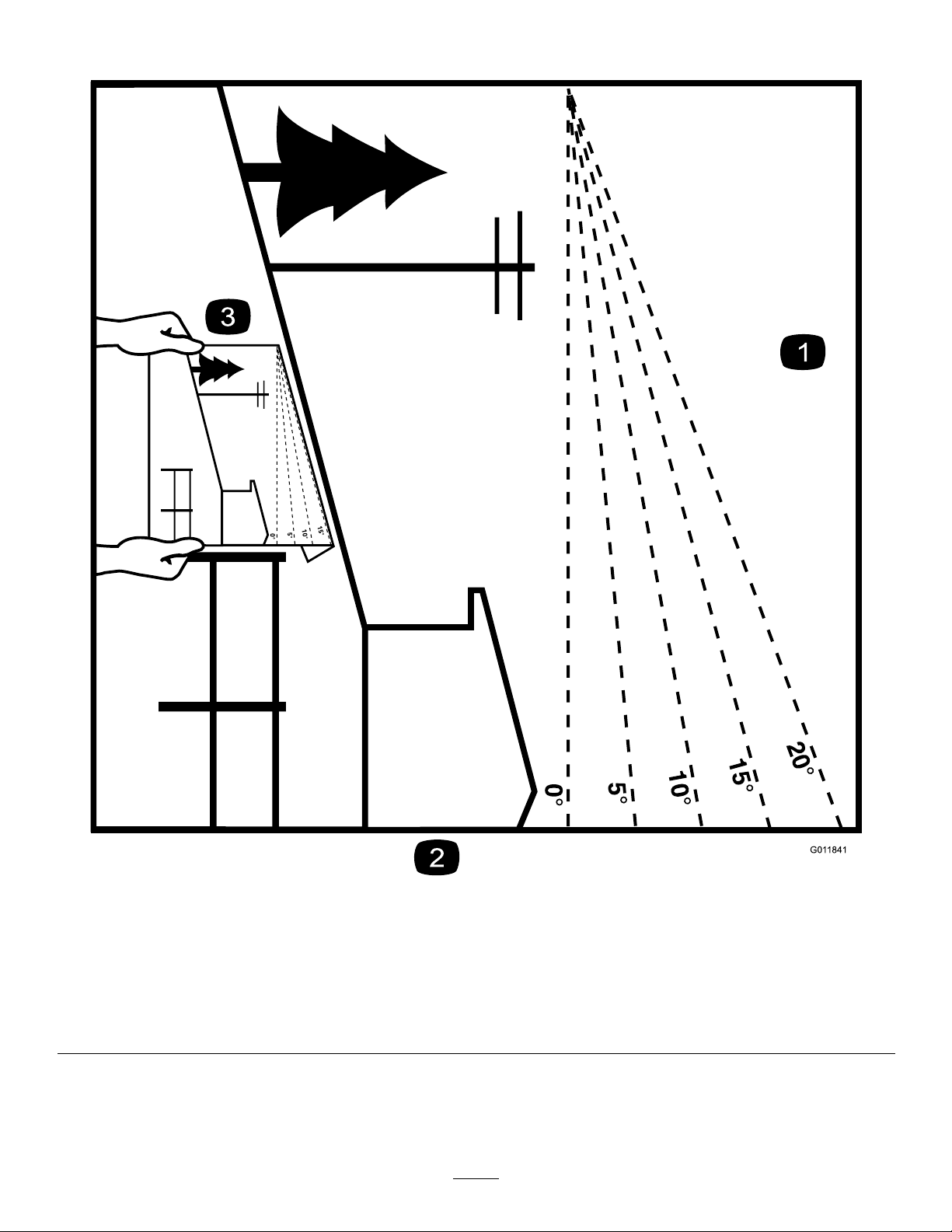
Figure3
Youmaycopythispageforpersonaluse.
1.Themaximumslopeyoucanoperatethemachineonis15degrees.Usetheslopecharttodeterminethedegreeofslopeof
hillsbeforeoperating.Donotoperatethismachineonaslopegreaterthan15degrees.Foldalongtheappropriateline
tomatchtherecommendedslope.
2.Alignthisedgewithaverticalsurface,atree,building,fencepole,etc.
3.Exampleofhowtocompareslopewithfoldededge
5
g011841
SafetyandInstructionalDecals
Safetydecalsandinstructionsareeasilyvisibletotheoperatorandarelocatednearanyarea
ofpotentialdanger.Replaceanydecalthatisdamagedormissing.
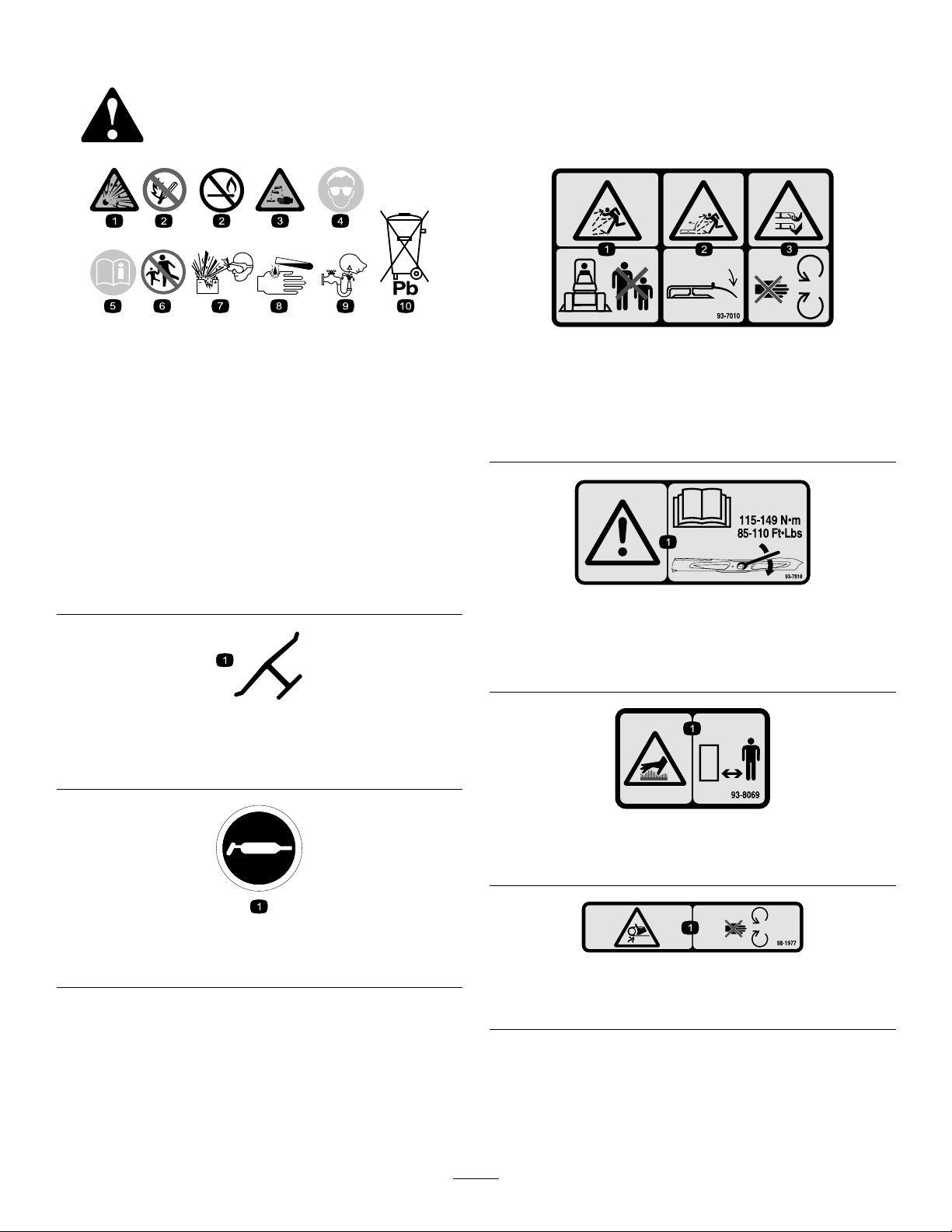
BatterySymbols
Someorallofthesesymbolsareonyourbattery.
1.Explosionhazard6.Keepbystandersaway
2.Nore,opename,or
smoking
3.Causticliquid/chemical
burnhazard
4.Weareyeprotection.9.Flusheyesimmediately
5.ReadtheOperator's
Manual.
fromthebattery .
7.Weareyeprotection;
explosivegasescan
causeblindnessandother
injuries.
8.Batteryacidcancause
blindnessorsevereburns.
withwaterandgetmedical
helpfast.
10.Containslead;donot
discard
Manufacturer'sMark
1.Indicatesthebladeisidentiedasapartfromtheoriginal
machinemanufacturer.
decalbatterysymbols
decal93-7010
93-7010
1.Thrownobjecthazard—keepbystandersaway.
2.Thrownobjecthazard,mower—keepthedeectorinplace.
3.Cutting/dismembermenthazardofhandorfoot,mower
blade—stayawayfrommovingparts.
decal93-7818
93-7818
1.Warning—readtheOperator'sManualforinstructionson
torquingthebladebolt/nutto1 15to149N∙m(85to110
ft-lb).
decaloemmarkt
decal93-8069
93-8069
1.Hotsurface/burnhazard—stayawayfromthehotsurface.
decal58-6520
58-6520
1.Grease
98-1977
1.Entanglementhazard,belt—stayawayfrommovingparts.
decal98-1977
6
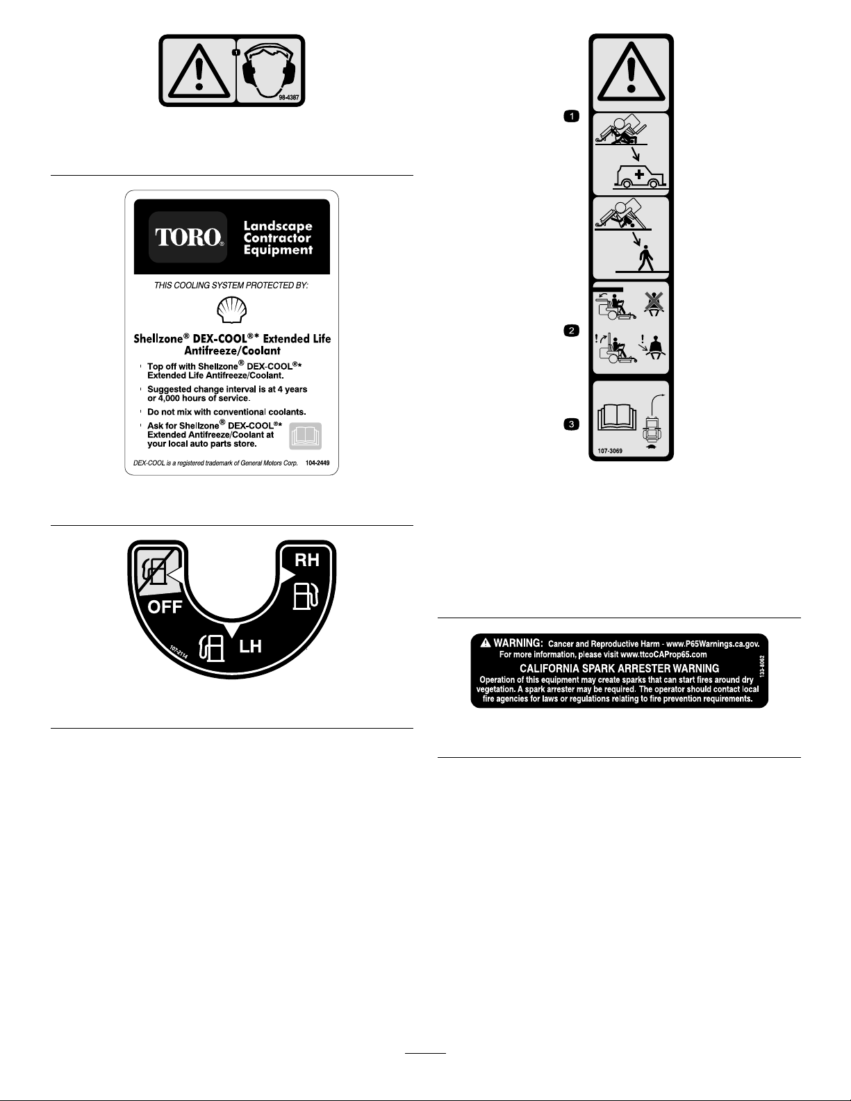
1.Warning—wearhearingprotection.
decal98-4387
98-4387
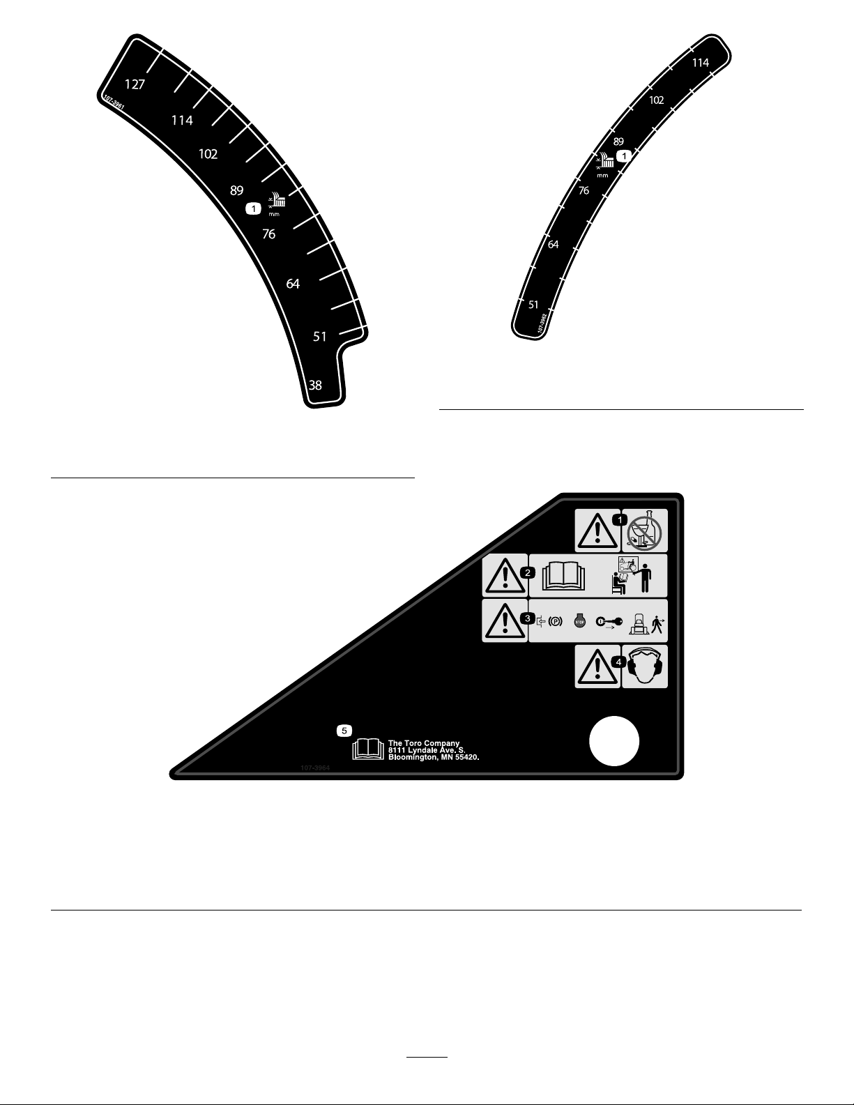
decal107-3069
decal104-2449
104-2449
1.Warning–thereisnorolloverprotectionwhentherollbaris
down.
2.Toavoidinjuryordeathfromarolloveraccident,keepthe
rollbarintheraisedandlockedpositionandweartheseat
belt.Lowertherollbaronlywhenabsolutelynecessary;do
notweartheseatbeltwhentherollbarisdown.
3.ReadtheOperator'sManual;driveslowlyandcarefully.
107-3069
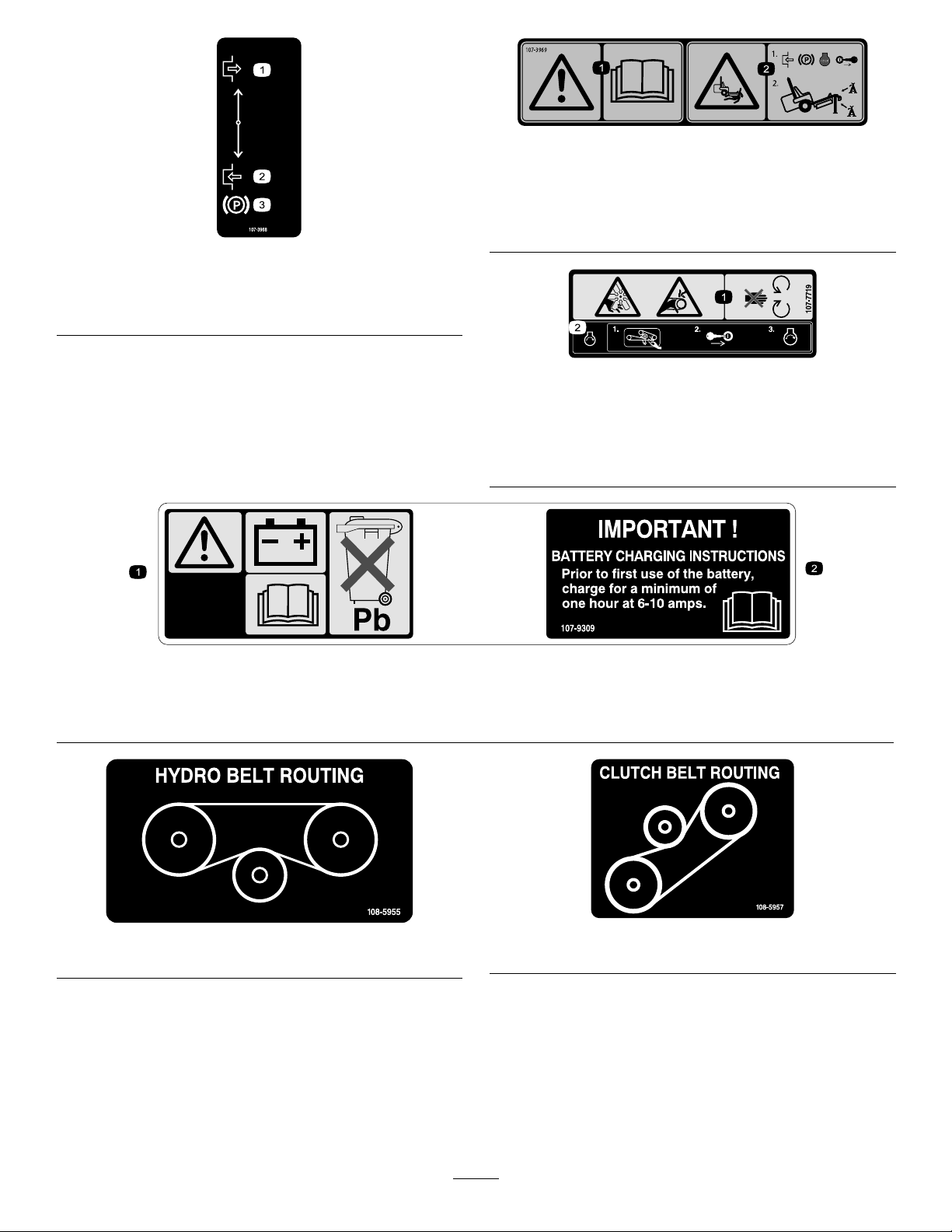
107-2114
decal107-2114
decal133-8062
133-8062
7
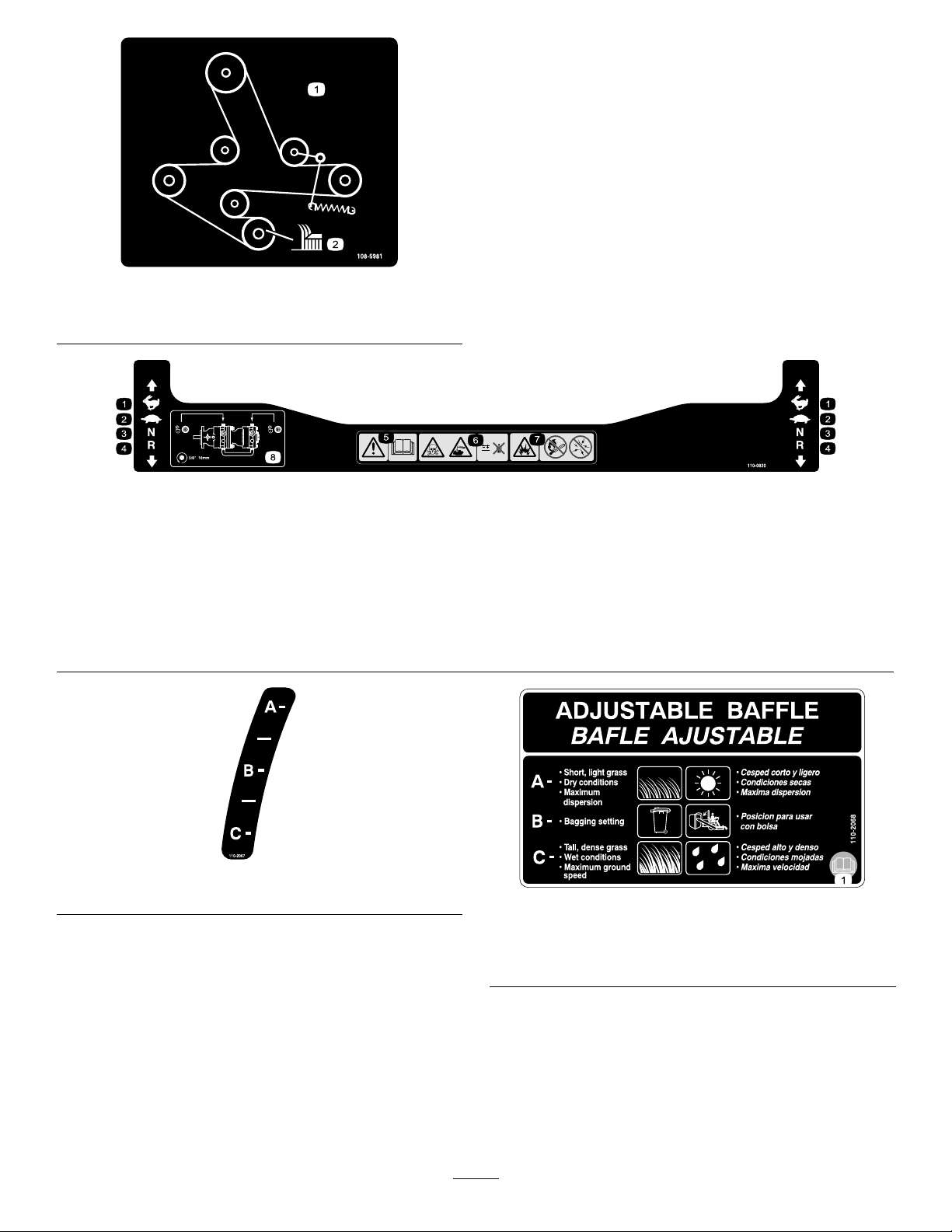
1.Heightofcutinmillimeters
decal107-3962
107-3962
1.Heightofcutinmillimeters
decal107-3961
107-3961
107-3964
1.Warning—donotusedrugsoralcohol.3.Warning—engagetheparkingbrake,
2.Warning—readtheOperator'sManual
andreceivetraining.
shutofftheengine,andremovethe
keybeforeleavingthemachine.
4.Warning—wearhearingprotection.
8
decal107-3964
5.ReadtheOperator'sManual.
107-3968
1.Disengage3.Parkingbrake
2.Engage
decal107-3969
107-3969
1.Warning—readtheOperator'sManual.
2.Crushinghazard,mower—engagetheparkingbrake,shut
offtheengine,andremovethekeybeforeworkingunder
themower.
decal107-3968
decal107-7719
107-7719
1.Cutting/dismembermenthazard,fanandentanglement
hazard,belt—stayawayfrommovingparts.
2.Beforestartingtheengine,cleangrassanddebrisfromthe
mowerbeltandpulleys,insertthekey,andstarttheengine.
107-9309
1.Warning—readtheOperator'sManualforinformationonchargingthebattery;containslead;donotdiscard.
2.ReadtheOperator'sManual.
decal108-5955
108-5955
decal107-9309
decal108-5957
108-5957
9
decal108-5981
108-5981
1.Beltrouting
2.Heightofcut
110-0820
1.Fast
2.Slow6.Poisonandcausticliquid/chemicalburnhazard—keepaway
3.Neutral
4.Reverse8.Tounlockthetractiondrive,turnthebypassvalve1complete
5.Warning—readtheOperator'sManual.
fromthebattery.
7.Explosionhazard—nore,openames,orsmoking;avoid
sparks.
revolutioncounterclockwiseusinga5/8inchor16mm
wrench.
decal110-0820
decal110-2067
110-2067
decal110-2068
110-2068
SideDischargeMachinesOnly
1.ReadtheOperator'sManual.
10
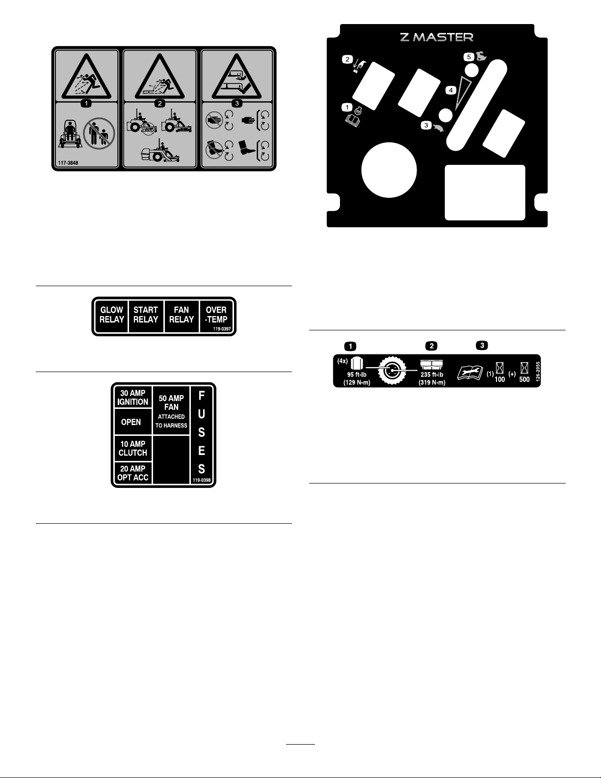
decal112-9028
112-9028
1.Warning—stayawayfrommovingparts;keepallguards
andshieldsinplace.
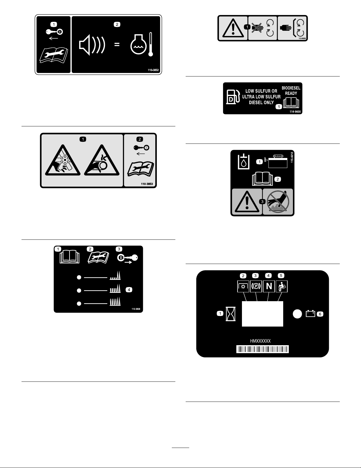
decal110-3852
110-3852
1.Removethekeyfrom
thekeyswitchandread
theinstructionsbefore
servicingorperforming
maintenance.
1.Cutting/dismemberment
hazard,fanand
entanglementhazard,
belt.
2.Continuoustonesignals
110-3853
2.Removethekeyfrom
theuserthattheengineis
overheating.
decal110-3853
thekeyswitchandread
theinstructionsbefore
servicingorperforming
maintenance.
1.ReadtheOperator'sManual.
1.Hydraulic-iudlevel
2.ReadtheOperator's
Manual.
decal114-9600
114-9600
decal115-4212
115-4212
3.Warning—donottouchthe
hotsurface.
1.ReadtheOperator's
Manual.
2.Readtheinstructions
beforeservicingor
performingmaintenance.
112-3858
RearDischargeMachinesOnly
3.Removethekeyfrom
4.Height-of-cutsettings.
decal112-3858
thekeyswitchbefore
adjustingtheheightofcut.
decal116-5610
116-5610
1.Hourmeter4.Neutral
2.Powertake-off(PTO)5.Operator-presenceswitch
3.Parkingbrake6.Battery
11
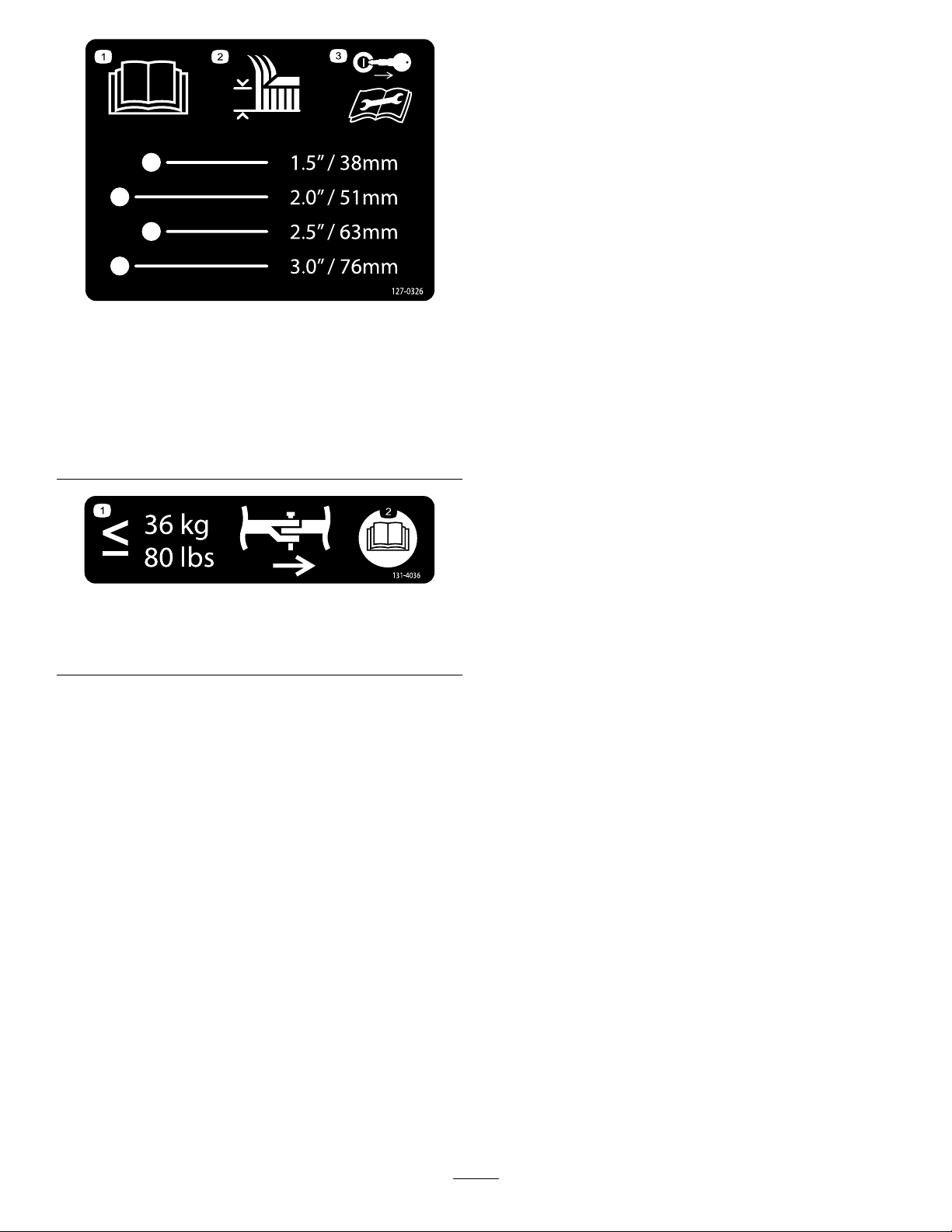
Reardischargemachinesonly:
117-3848
1.Thrownobjecthazard—keepbystandersaway.
2.Thrownobjecthazard,raiseddeector—donotoperate
withoutthedeector,dischargecover,orgrasscollection
systeminplace.
3.Cutting/dismembermenthazardofhandorfoot,mower
blade—stayawayfrommovingparts;keepallguardsand
shieldsinplace.
decal117-3848
decal121-7562
121-7562
1.Pushtostart4.Variablespeedcontrol
2.ReadtheOperator’s
Manualformore
informationonpreheating
theengine.
3.Slow
5.Fast
decal119-0397
119-0397
decal126-2055
126-2055
1.Wheellugnuttorque129N∙m(95ft-lb)(4x)
2.Wheelhubnuttorque319N∙m(235ft-lb)
3.ReadandunderstandtheOperator’sManualbefore
performinganymaintenance,checktorqueafterrst100
hoursthenevery500hoursthereafter.
decal119-0398
119-0398
12
127-0326
SideDischargeMachinesOnly
decal127-0326
1.ReadtheOperator's
Manual.
2.Heightofcut
1.Maximumdrawbarpull36
kg(80lb).
3.Removethekeyand
readtheOperator's
Manualbeforeperforming
maintenanceorservicing
themachine.
decal131-4036
131-4036
2.ReadtheOperator's
Manual.
13
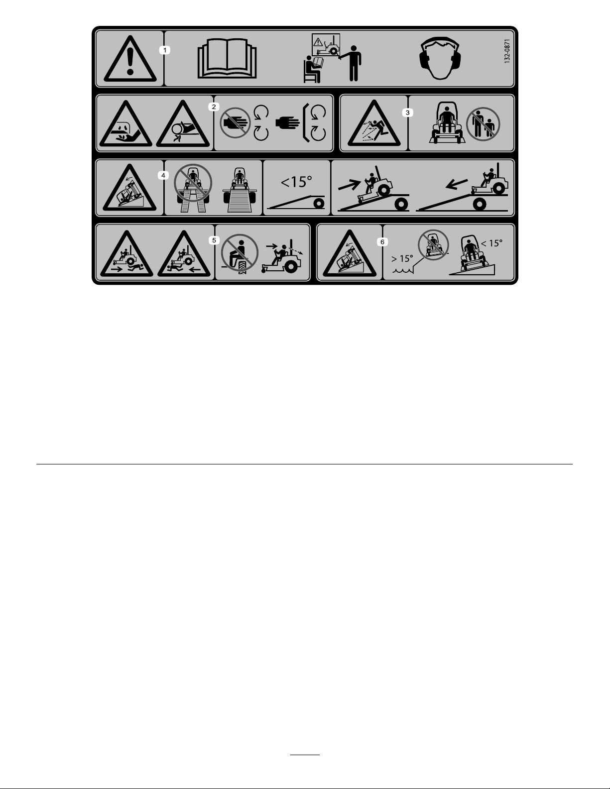
132-0871
Note:Thismachinecomplieswiththeindustrystandardstabilitytestinthestaticlateralandlongitudinaltestswiththemaximum
recommendedslopeindicatedonthedecal.ReviewtheinstructionsforoperatingthemachineonslopesintheOperator’sManualas
wellastheconditionsinwhichyouwouldoperatethemachinetodeterminewhetheryoucanoperatethemachineintheconditionson
thatdayandatthatsite.Changesintheterraincanresultinachangeinslopeoperationforthemachine.
decal132-0871
1.Warning—readtheOperator’sManual;alloperatorsshould
betrainedbeforeoperatingthemachine;wearhearing
protection.
2.Cutting/dismembermenthazardofhand—stayawayfrom
movingparts;keepallguardsandshieldsinplace.
3.Thrownobjecthazard—keepbystandersaway.
4.Tippinghazard—donotusedualrampswhenloadingontoa
trailer;use1rampwideenoughforthemachine;usearamp
withaslopelessthan15°;backuptheramp(inreverse)and
driveforwardofftheramp.
5.Runoverhazard—donotcarrypassengers;lookbehindyou
whenmovinginreverse.
6.Tippinghazard—donotusethemachineneardrop-offsor
onslopesgreaterthan15°;onlyoperateacrossslopesless
than15°.
14
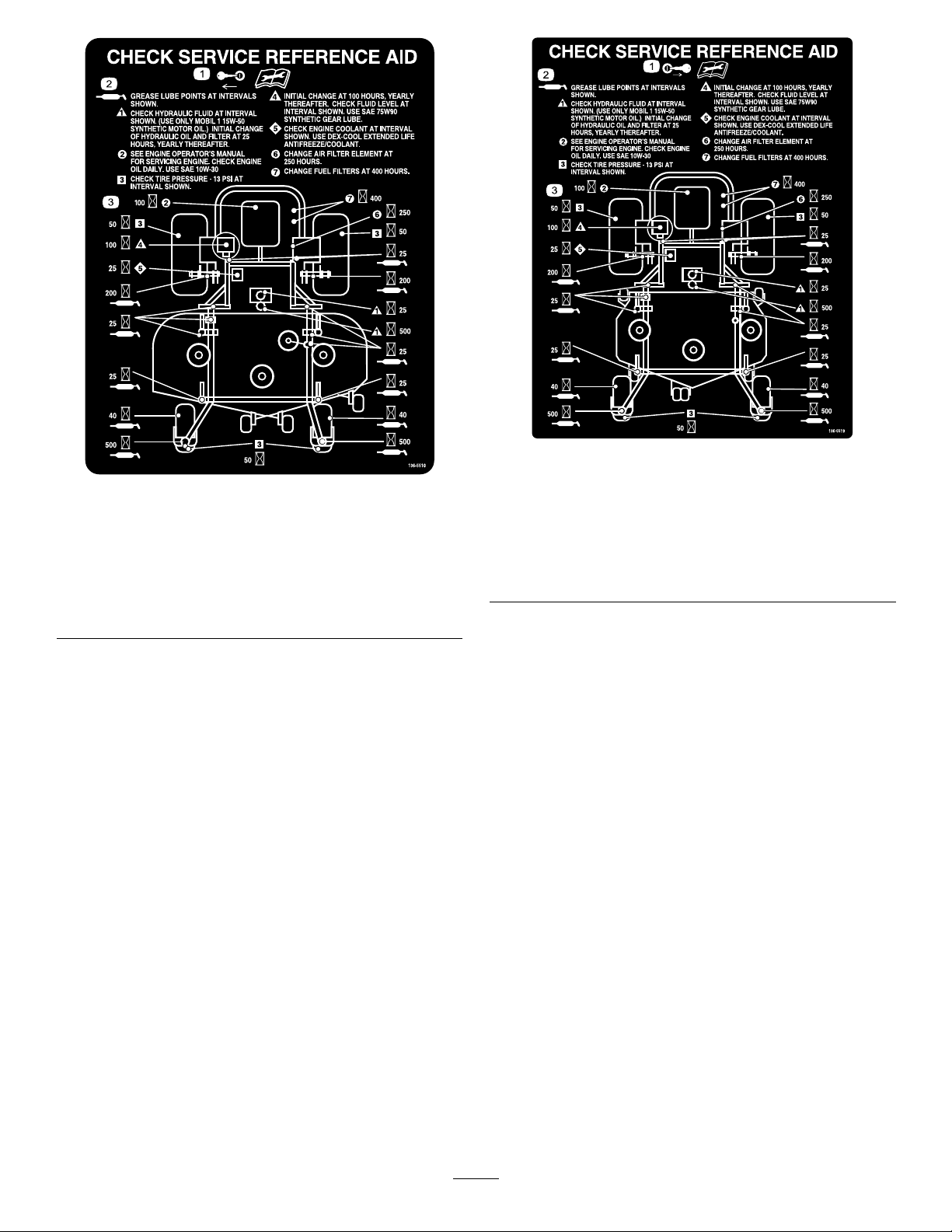
SideDischargeMachinesOnly
1.Removethekeyand
readtheOperator's
Manualbeforeperforming
maintenance.
2.Greasepoint
decal136-5519
136-5519
decal136-5510
RearDischargeMachinesOnly
136-5510
3.Hourinterval
3.Hourinterval
1.Removethekeyand
readtheOperator's
Manualbeforeperforming
maintenance.
2.Greasepoint
15
ProductOverview
Controls
Becomefamiliarwithallthecontrolsbeforeyoustart
theengineandoperatethemachine.
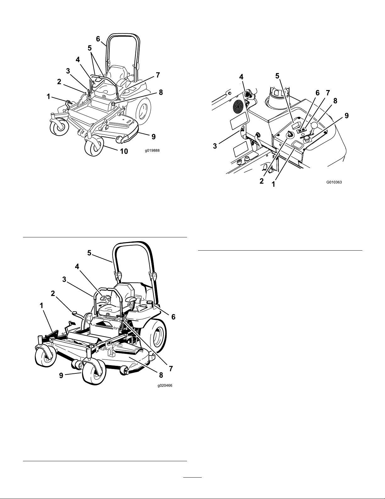
ControlPanel
g019888
Figure4
SideDischargeMachine
1.Height-of-cutdecklift
pedal
2.Transportlock
3.Parking-brakelever8.Fuelcap
4.Controls
5.Motion-controllever
6.Rollbar
7.Seatbelt
9.Mowerdeck
10.Casterwheel
Figure6
1.Hourmeter
2.Keyswitch7.Engine-temperaturelight
3.Fuel-selectorvalve8.Throttlecontrol
4.Audiblealarm
5.Glow-plugswitch
6.Glow-pluglight
9.PTOswitch
KeySwitch
Thekeyswitch,usedtostartandshutofftheengine,
has3positions:OFF,RUN,andSTART.Referto
StartingandShuttingOfftheEngine(page26).
HourMeter
Thehourmeterrecordsthenumberofhoursthe
enginehasoperated.Itoperateswhentheengine
isrunning.Usethesetimesforschedulingregular
maintenance(Figure6).
g010363
Figure5
RearDischargeMachine
1.ZStand
2.Height-of-cutlever
3.Motion-controllever8.Mowerdeck
4.Seatbelt9.Casterwheel
5.Rollbar
©
6.Fuelcap(bothsides)
7.Parking-brakelever
Safety-InterlockIndicators
g020466
Therearesymbolsonthehourmeterthatindicate
withablacktrianglethattheinterlockcomponentis
positionedcorrectly(Figure7).
16

Battery-IndicatorLight
AudibleAlarm
IfyouturnthekeyswitchtotheONpositionfora
fewseconds,thebatteryvoltagedisplaysinthearea
wherethehoursarenormallydisplayed.
Thebatterylightturnsonwhentheignitionisturned
onandwhenthechargeisbelowthecorrectoperating
level(Figure7).
Figure7
1.Safety-interlocksymbols
2.Hourmeter
3.Batterylight
ThrottleControl
Thethrottlecontrolstheenginespeed,andithasa
continuous-variablesettingfromtheSLOWtoFAST
position(Figure6).
Thismachinehasanaudiblealarmthatalertstheuser
toshutofftheengine;otherwise,enginedamagecan
occurfromoverheating.RefertoOperatingwiththe
OverheatSensor(page33).
Fuel-SelectorValve
Thefuel-selectorvalveislocatedbehindtheseat.
Closethefuel-selectorvalvewhentransportingor
storingmower.
Movetheselectorvalvetotheleftorrightpositionfor
operation.
Attachments/Accessories
g009610
AselectionofT oroapprovedattachmentsand
accessoriesisavailableforusewiththemachine
toenhanceandexpanditscapabilities.Contact
yourAuthorizedServiceDealerorauthorizedT oro
distributororgotowww.Toro.comforalistofall
approvedattachmentsandaccessories.
Toensureoptimumperformanceandcontinuedsafety
certicationofthemachine,useonlygenuineT oro
replacementpartsandaccessories.Replacement
partsandaccessoriesmadebyothermanufacturers
couldbedangerous,andsuchusecouldvoidthe
productwarranty.
Neutral-LockPosition
UsetheNEUTRAL-LOCKpositionwiththe
safety-interlocksystemtoengageandtodetermine
theNEUTRALposition.
Glow-PlugLight
Theglow-plugindicatorlightturnsonwhenthe
glow-plugbuttonisengaged(Figure6).
Glow-PlugSwitch
Thisswitchactivatestheglowplugsandisindicated
bytheglow-pluglight.Holddowntheglow-plugswitch
for10secondspriortostartingthemachine.
TemperatureLight
Thetemperaturelightcomesonwhentheengineis
overheating(Figure6).
17

Operation
Note:Determinetheleftandrightsidesofthe
machinefromthenormaloperatingposition.
BeforeOperation
BeforeOperationSafety
GeneralSafety
•Neverallowchildrenoruntrainedpeopleto
operateorservicethemachine.Localregulations
mayrestricttheageoftheoperator.Theowner
isresponsiblefortrainingalloperatorsand
mechanics.
•Becomefamiliarwiththesafeoperationofthe
equipment,operatorcontrols,andsafetysigns.
•Knowhowtostopthemachineandshutoffthe
enginequickly.
•Checkthatoperator-presencecontrols,safety
switches,andshieldsareattachedandfunctioning
properly.Donotoperatethemachineunlessthey
arefunctioningproperly.
•Beforemowing,alwaysinspectthemachineto
ensurethattheblades,bladebolts,andcutting
assembliesareingoodworkingcondition.
Replacewornordamagedbladesandboltsinsets
topreservebalance.
•Inspecttheareawhereyouwillusethemachine
andremoveallobjectsthatthemachinecould
throw.
•Evaluatetheterraintodeterminetheappropriate
equipmentandanyattachmentsoraccessories
requiredtooperatethemachineproperlyand
safely.
containersontheground,awayfromyourvehicle
beforelling.
•Removetheequipmentfromthetruckortrailer
andrefuelitwhileitisontheground.Ifthisisnot
possible,thenrefuelfromaportablecontainer
ratherthanafuel-dispensernozzle.
•Donotoperatethemachinewithouttheentire
exhaustsysteminplaceandinproperworking
condition.
•Keepthefuel-dispensernozzleincontactwith
therimofthefueltankorcontaineropeningat
alltimesuntilfuelingiscomplete.Donotusea
nozzlelock-opendevice.
•Ifyouspillfuelonyourclothing,changeyour
clothingimmediately.Wipeupanyfuelthatspills.
•Neveroverllthefueltank.Replacethefuelcap
andtightenitsecurely.
•Storefuelinanapprovedcontainerandkeepit
outofthereachofchildren.Neverbuymorethan
a30-daysupplyoffuel.
•Donotllthefueltankcompletelyfull.Addfuelto
thefueltankuntilthelevelis6to13mm(1/4to
1/2inch)belowthebottomofthellerneck.This
emptyspaceinthetankallowsfueltoexpand.
–Avoidprolongedbreathingofvapors.
–Keepyourfaceawayfromthenozzleandfuel
tankopening.
–Avoidcontactwithskin;washoffspillswith
soapandwater.
PerformingDaily
Maintenance
Beforestartingthemachineeachday,performthe
EachUse/DailyprocedureslistedinMaintenance
(page39).
FuelSafety
•Toavoidpersonalinjuryorpropertydamage,use
extremecareinhandlingfuel.Fuelvaporsare
ammableandexplosive.
•Extinguishallcigarettes,cigars,pipes,andother
sourcesofignition.
•Useonlyanapprovedfuelcontainer.
•Donotremovethefuelcaporaddfueltothefuel
tankwhiletheengineisrunningorwhilehot.
•Donotrefuelthemachineindoors.
•Donotstorethemachineorfuelcontainerwhere
thereisanopename,spark,orpilotlight,such
asonawaterheateroronotherappliances.
•Donotllcontainersinsideavehicleoronatruck
ortrailerbedwithaplasticliner.Alwaysplace
AddingFuel
RecommendedFuel
Theenginerunsonclean,freshdieselfuelwith
aminimumoctaneratingof40.Purchasefuelin
quantitiesthatcanbeusedwithin30daystoensure
fuelfreshness.
Usesummer-gradedieselfuel(No.2-D)at
temperaturesabove-7°C(20°F)andwinter-grade
dieselfuel(No.1-DorNo.1-D/2-Dblend)below
-7°C(20°F).Useofwinter-gradedieselfuelatlower
temperaturesprovideslowerashpointandpour
pointcharacteristics,thereforeeasingstartabilityand
lesseningchancesofchemicalseparationofthefuel
duetolowertemperatures(waxappearance,which
maypluglters).
18
Usingsummer-gradedieselfuelabove-7°C
(20°F)contributestowardlongerlifeofthepump
components.
Important:Donotusekeroseneorgasoline
insteadofdieselfuel.Failuretoobservethis
cautionwilldamagetheengine.
BiodieselReady
Thismachinecanalsouseabiodieselblendedfuel
ofuptoB20(20%biodiesel,80%petrodiesel).The
petrodieselportionshouldbeloworultralowsulfur.
Observethefollowingprecautions:
•Thebiodieselportionofthefuelmeetspecication
ASTMD6751orEN14214.
•TheblendedfuelcompositionshouldmeetASTM
D975orEN590.
•Paintedsurfacesmaybedamagedbybiodiesel
blends.
•UseB5(biodieselcontentof5%)orlesserblend
incoldweather.
•Monitorseals,hoses,gasketsincontactwithfuel
astheymaydegradeovertime.
•Fuellterpluggingmaybeexpectedforatime
afterconvertingtobiodieselblends.
•Contactyourdistributorformoreinformationon
biodiesel.
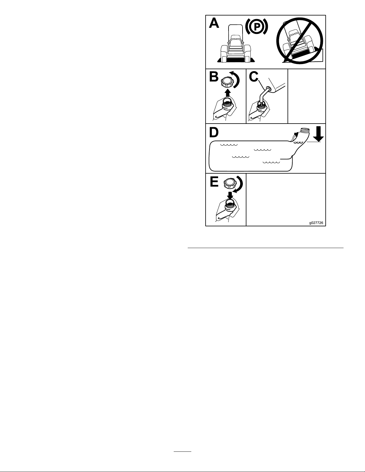
FillingtheFuelTank
1.Parkthemachineonalevelsurface.
2.Engagetheparkingbrake.
3.Shutofftheengineandremovethekey.
4.Cleanaroundthefuel-tankcap.
5.Fillthefueltanktothebottomofthellerneck
(Figure8).
Note:Donotllthefueltankcompletelyfull.
Theemptyspaceinthetankallowsthefuelto
expand.
g027726
Figure8
SwitchingtheFuelTanks
Important:Donotallowthemachinetorunout
offuel,asthiscandamagethemachine.
Thefuel-selectorvalveislocatedbehindtheleftside
oftheseat.
Themachinehas2fueltanks:1tankisontheleft
sideand1isontherightside.Eachtankconnectsto
thefuel-selectorvalve.Fromthere,acommonfuel
lineleadstotheengine(Figure9).
Tousetheleftfueltank,rotatethefuel-selector
valvetotheleft.T ousetherightfueltank,rotatethe
fuel-selectorvalvetotheright(Figure9).
Closethefuel-selectorvalvebeforetransportingor
storingthemachine.
19
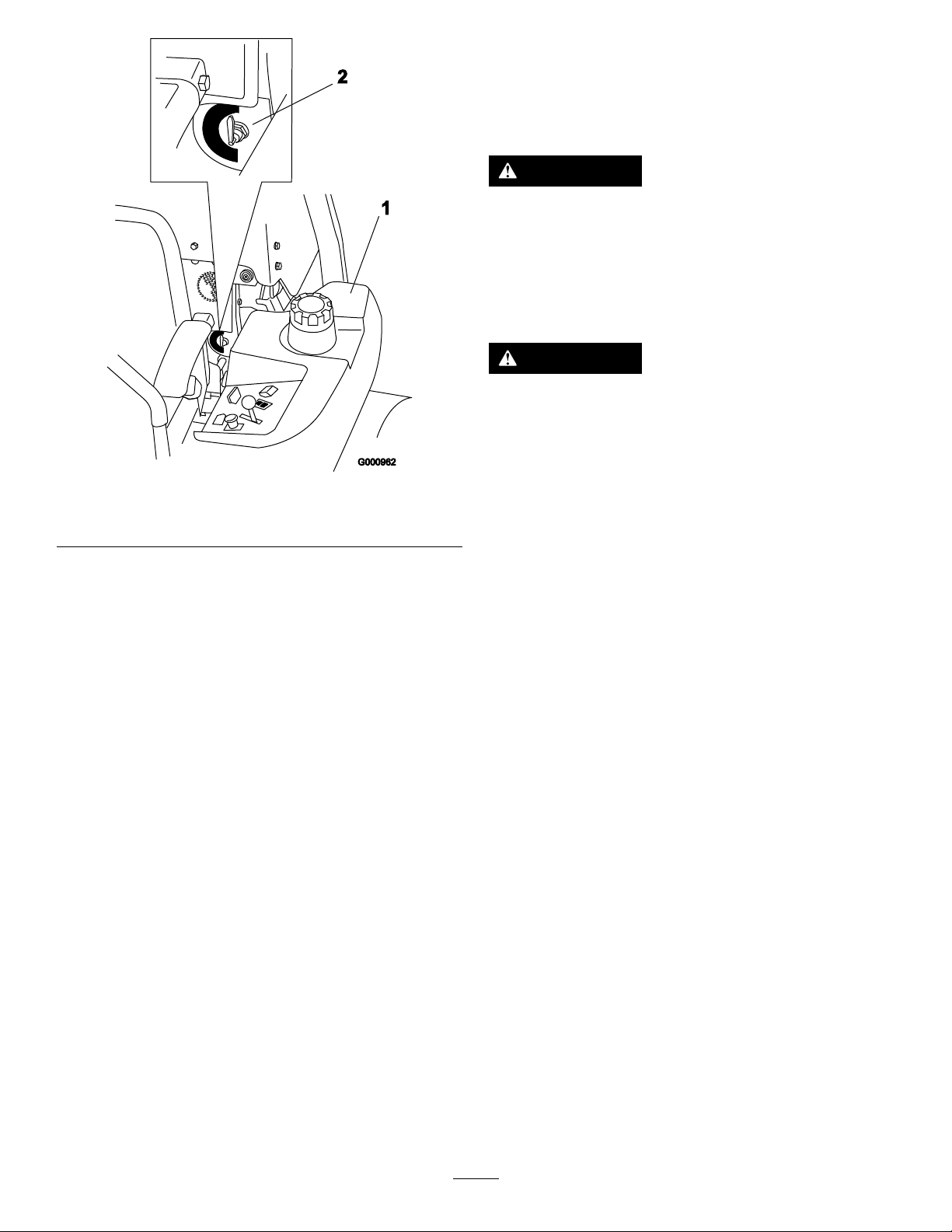
1.Leftfueltank
Figure9
Usingthe
Rollover-ProtectionSystem
(ROPS)
WARNING
Toavoidinjuryordeathfromrollover,keep
therollbarinthefullyraised,lockedposition
andusetheseatbelt.
Ensurethattheseatissecuredtothe
machine.
WARNING
Thereisnorolloverprotectionwhentheroll
barisinthedownposition.
•Lowertherollbaronlywhenabsolutely
necessary.
g000962
•Donotweartheseatbeltwhentherollbar
isinthedownposition.
2.Fuel-selectorvalve
•Driveslowlyandcarefully.
BreakinginaNewMachine
Newenginestaketimetodevelopfullpower.Mower
decksanddrivesystemshavehigherfrictionwhen
new,placingadditionalloadontheengine.Allow
40to50hoursofbreak-intimefornewmachinesto
developfullpowerandbestperformance.
•Raisetherollbarassoonasclearance
permits.
•Checkcarefullyforoverheadclearances
(i.e.,branches,doorways,electricalwires)
beforedrivingunderanyobjectsanddo
notcontactthem.
LoweringtheRollBar
Important:Lowertherollbaronlywhen
absolutelynecessary.
1.Removethehairpincottersandremovethe2
pins(Figure11).
2.Lowertherollbartothedownposition(Figure
10).
Note:Thereare2downpositions;referto
Figure10.
3.Installthe2pinsandsecurethemwiththe
hairpincotters(Figure11).
20

Figure10
UsingtheSafety-Interlock
System
WARNING
Ifsafety-interlockswitchesaredisconnected
ordamaged,themachinecouldoperate
unexpectedlycausingpersonalinjury.
•Donottamperwiththeinterlockswitches.
•Checktheoperationoftheinterlock
switchesdaily,andreplaceanydamaged
g004954
switchesbeforeoperatingthemachine.
1.Full-downposition2.Downpositionwiththe
baggerinstalled
Important:Ensurethatyousecuretherear
partoftheseatwiththeseatlatch.
RaisingtheRollBar
Important:Alwaysusetheseatbeltwiththeroll
barintheraisedposition.
1.Removethehairpincottersandremovethe2
pins(Figure11).
2.Raisetherollbartotheuprightposition,install
the2pins,andsecurethemwiththehairpin
cotters(Figure11).
Understandingthe
Safety-InterlockSystem
Thesafety-interlocksystemisdesignedtopreventthe
enginefromstartingunless:
•Theparkingbrakeisengaged.
•Theblade-controlswitch(PTO)isdisengaged.
•Themotion-controlleversareintheNEUTRAL-LOCK
position.
Thesafety-interlocksystemalsoisdesignedtoshutoff
theenginewhenthetractioncontrolsaremovedfrom
thelockedpositionwiththeparkingbrakeengagedor
ifyourisefromtheseatwhenthePTOisengaged.
Thehourmeterhassymbolstonotifytheuserwhen
theinterlockcomponentisinthecorrectposition.
Whenthecomponentisinthecorrectposition,a
trianglelightsupinthecorrespondingsquare.
Figure11
1.Rollbar3.Pin
2.Raisedposition4.Hairpincotter
g009612
Figure12
1.Triangleslightupwhentheinterlockcomponentsareinthe
correctposition
TestingtheSafety-Interlock
g004955
System
ServiceInterval:Beforeeachuseordaily
Testthesafety-interlocksystembeforeyouusethe
machineeachtime.Ifthesafetysystemdoesnot
21
operateasdescribedbelow,haveanAuthorized
ServiceDealerrepairthesafetysystemimmediately .
1.Sittingontheseat,engagetheparkingbrake
andmovetheblade-controlswitch(PTO)tothe
ONposition.Trystartingtheengine;theengine
shouldnotstart.
2.Sittingontheseat,engagetheparkingbrake
andmovetheblade-controlswitch(PTO)tothe
OFFposition.Moveeithermotion-controllever
(outoftheNEUTRAL-LOCKposition).Trystarting
theengine;theengineshouldnotstart.Repeat
fortheothercontrollever.
3.Sittingontheseat,engagetheparkingbrake,
movetheblade-controlswitch(PTO)totheOFF
position,andmovethemotion-controllevers
totheNEUTRAL-LOCKposition.Nowstartthe
engine.Whiletheengineisrunning,disengage
theparkingbrake,engagetheblade-control
switch(PTO),andriseslightlyfromtheseat;the
engineshouldshutoff.
4.Sittingontheseat,engagetheparkingbrake,
movetheblade-controlswitch(PTO)totheOFF
position,andmovethemotion-controllevers
totheNEUTRAL-LOCKposition.Nowstartthe
engine.Whiletheengineisrunning,center
eithermotioncontrolandmove(forwardor
reverse);theengineshouldshutoff.Repeatfor
othermotioncontrol.
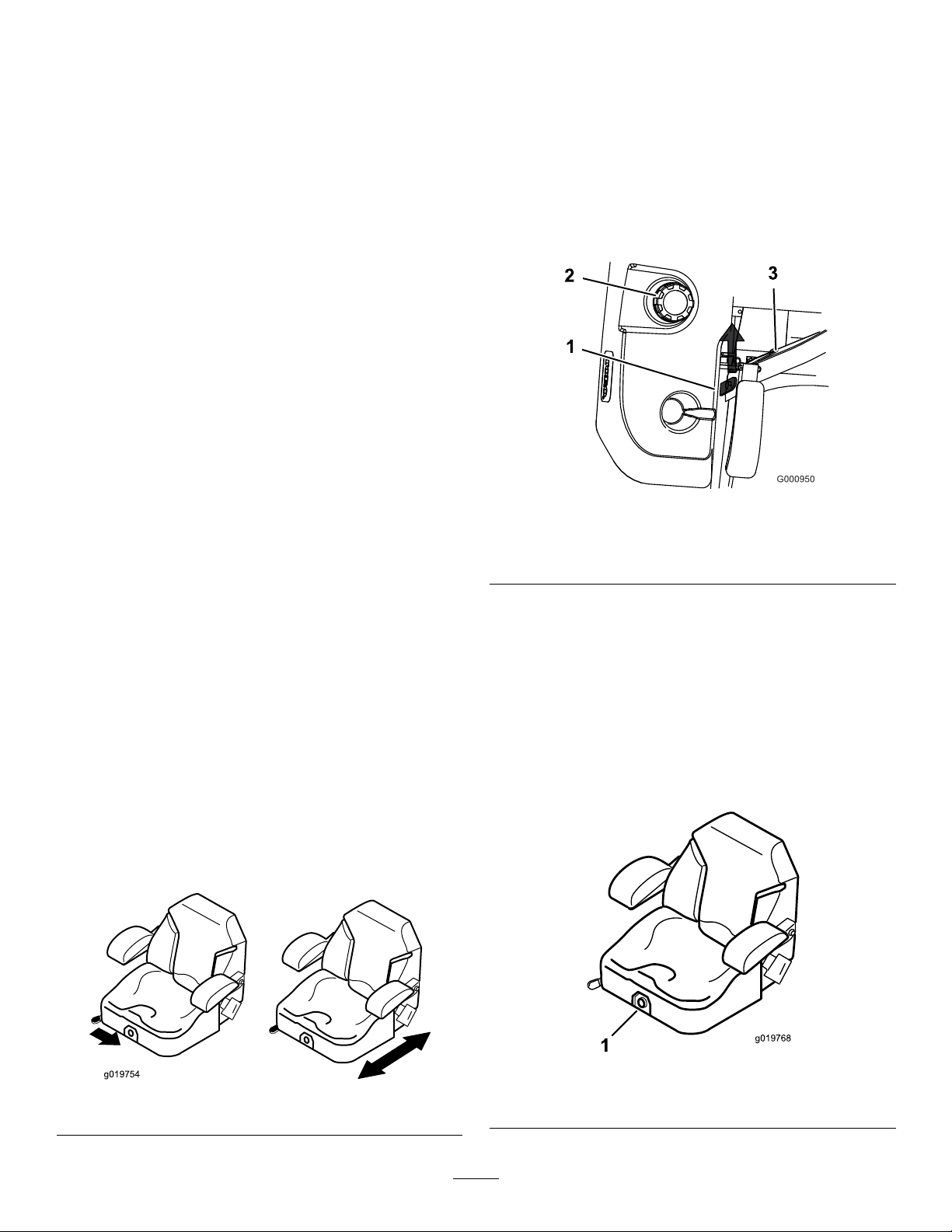
UnlatchingtheSeat
1.Movetheseattothemostrearwardposition.
Note:Thispreventsinterferencewhenyou
raisetheseat.
2.Pushtheseatlatchrearwardtounlatchtheseat.
3.Raisetheseatup(Figure14).
Note:Thisallowsaccesstothemachineunder
theseat.
g000950
Figure14
1.Seatlatch3.Seat
2.Fuelcap
5.Sittingontheseat,disengagetheparkingbrake,
movetheblade-controlswitch(PTO)totheOFF
position,andmovethemotion-controllevers
totheNEUTRAL-LOCKposition.Trystartingthe
engine;theengineshouldnotstart.
PositioningtheSeat
Theseatmovesforwardandbackward.Positionthe
seatwhereyouhavethebestcontrolofthemachine
andaremostcomfortable.
Toadjust,movetheleversidewaystounlocktheseat
(Figure13).
Figure13
ChangingtheSeat
Suspension
Theseatisadjustabletoprovideasmoothand
comfortableride.Positiontheseatwhereyouare
mostcomfortable.
Toadjustit,turntheknobinfronteitherdirectionto
providethebestcomfort(Figure15).
g019768
g019754
1.Seat-suspensionknob
Figure15
22

DuringOperation
DuringOperationSafety
GeneralSafety
•Theowner/operatorcanpreventandisresponsible
foraccidentsthatmaycausepersonalinjuryor
propertydamage.
•Wearappropriateclothing,includingeye
protection;longpants;slip-resistant,substantial
footwear;andhearingprotection.Tiebacklong
hairanddonotwearloosejewelry.
•Useyourfullattentionwhileoperatingthe
machine.Donotengageinanyactivitythat
causesdistractions;otherwise,injuryorproperty
damagemayoccur.
•Donotoperatethemachinewhileill,tired,or
undertheinuenceofalcoholordrugs.
•Nevercarrypassengersonthemachineandkeep
bystandersandpetsawayfromthemachine
duringoperation.
•Operatethemachineonlyingoodvisibilitytoavoid
holesorhiddenhazards.
•Avoidmowingonwetgrass.Reducedtraction
couldcausethemachinetoslide.
•Ensurethatalldrivesareinneutral,theparking
brakeisengaged,andyouareintheoperating
positionbeforeyoustarttheengine.
•Keepyourhandsandfeetawayfromthecutting
units.Keepclearofthedischargeopeningatall
times.
•Lookbehindanddownbeforebackinguptobe
sureofaclearpath.
•Usecarewhenapproachingblindcorners,shrubs,
trees,orotherobjectsthatmayobscureyour
vision.
•Donotmowneardrop-offs,ditches,or
embankments.Themachinecouldsuddenlyroll
overifawheelgoesovertheedgeoriftheedge
givesway.
•Stopthebladeswheneveryouarenotmowing.
•Stopthemachine,shutofftheengine,remove
thekey,andinspectthebladesafterstrikingan
objectorifthereisanabnormalvibrationinthe
machine.Makeallnecessaryrepairsbefore
resumingoperation.
•Slowdownandusecautionwhenmakingturns
andcrossingroadsandsidewalkswiththe
machine.Alwaysyieldtheright-of-way.
•Disengagethedrivetothecuttingunit,shutoffthe
engine,andremovethekeybeforeadjustingthe
heightofcut(unlessyoucanadjustitfromthe
operatingposition).
•Neverrunanengineinanareawhereexhaust
gasesareenclosed.
•Neverleavearunningmachineunattended.
•Beforeleavingtheoperatingposition(including
toemptythecatchersortounclogthechute),do
thefollowing:
–Stopthemachineonlevelground.
–Disengagethepowertakeoffandlowerthe
attachments.
–Engagetheparkingbrake.
–Shutofftheengineandremovethekey .
–Waitforallmovingpartstostop.
•Donotoperatethemachinewhenthereistherisk
oflightning.
•Donotusethemachineasatowingvehicleunless
ithasahitchinstalled.
•Donotchangethegovernorspeedoroverspeed
theengine.
•Useonlyaccessoriesandattachmentsapproved
byToro.
•Thismachineproducessoundlevelsinexcess
of85dBAattheoperator’searandcancause
hearinglossthroughextendedperiodsof
exposure.
g229846
Figure16
1.Wearhearingprotection.
RolloverProtectionSystem
(ROPS)Safety
•Donotremovetherollbarfromthemachine.
•Ensurethattheseatbeltisattachedandthatyou
canreleaseitquicklyinanemergency.
•Alwayswearyourseatbeltwhentherollbarisup.
•Checkcarefullyforoverheadobstructionsanddo
notcontactthem.
•Keeptherollbarinsafeoperatingconditionby
thoroughlyinspectingitperiodicallyfordamage
andkeepingallthemountingfastenerstight.
•Replaceadamagedrollbar.Donotrepairoralter
it.
SlopeSafety
•Slopesareamajorfactorrelatedtolossofcontrol
androlloveraccidents,whichcanresultinsevere
23
injuryordeath.Theoperatorisresponsiblefor
safeslopeoperation.Operatingthemachineon
anysloperequiresextracaution.Beforeusingthe
machineonaslope,dothefollowing:
–Reviewandunderstandtheslopeinstructions
inthemanualandonthemachine.
–Useanangleindicatortodeterminethe
approximateslopeangleofthearea.
–Neveroperateonslopesgreaterthan15
degrees.
–Evaluatethesiteconditionsofthedayto
determineiftheslopeissafeformachine
operation.Usecommonsenseandgood
judgmentwhenperformingthisevaluation.
Changesintheterrain,suchasmoisture,can
quicklyaffecttheoperationofthemachineon
aslope.
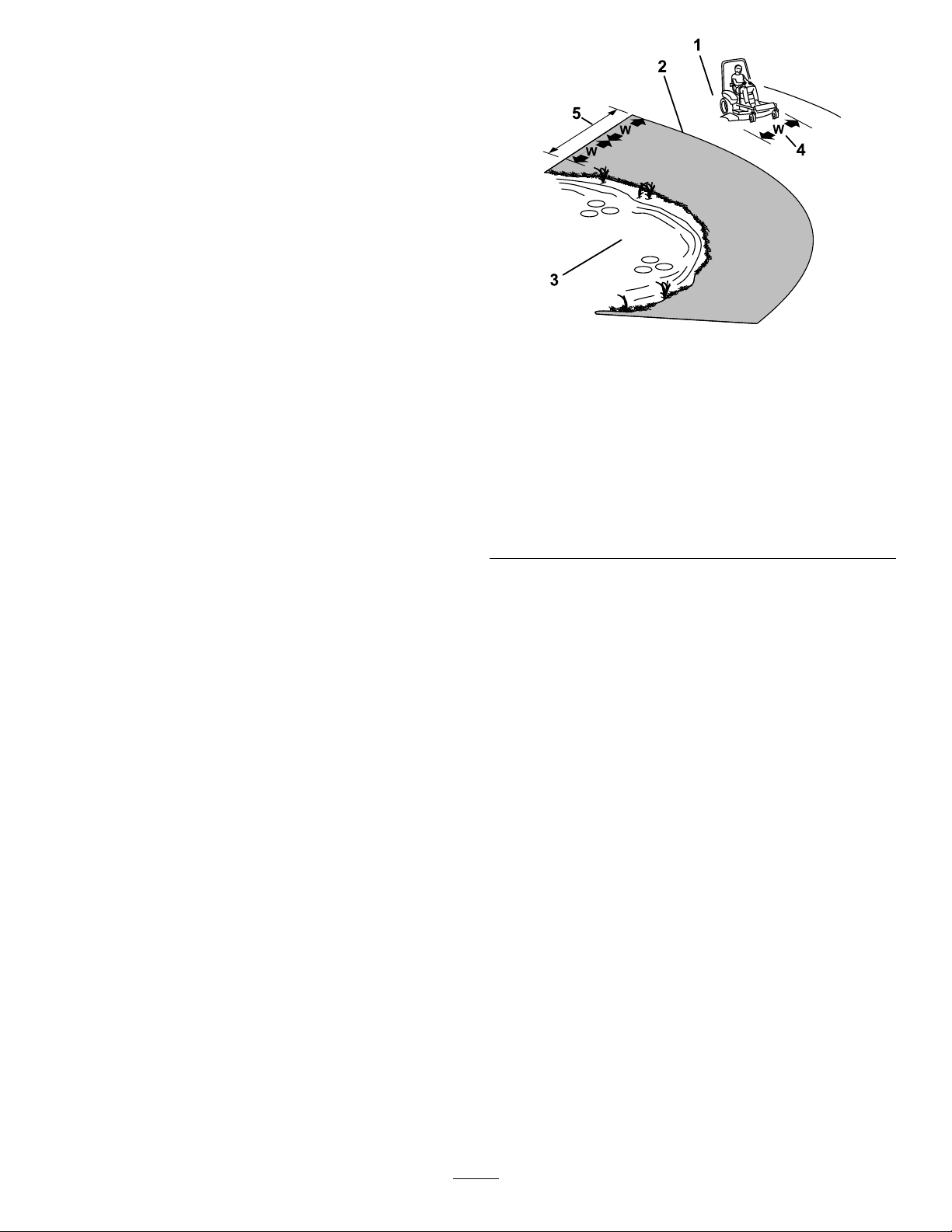
•Identifyhazardsatthebaseoftheslope.Do
notoperatethemachineneardrop-offs,ditches,
embankments,water,orotherhazards.The
machinecouldsuddenlyrolloverifawheelgoes
overtheedgeortheedgecollapses.Keepasafe
distance(twicethewidthofthemachine)between
themachineandanyhazard.Useawalk-behind
machineorahandtrimmertomowthegrassin
theseareas.
1.SafeZone—usethe
machinehereonslopes
lessthan15degreesor
atareas.
2.DangerZone—usea
walk-behindmowerand/or
ahandtrimmeronslopes
greaterthan15degrees
andneardrop-offsor
water.
3.Water
g221745
Figure17
4.W=widthofthemachine
5.Keepasafedistance
(twicethewidthofthe
machine)betweenthe
machineandanyhazard.
•Avoidstarting,stopping,orturningthemachineon
slopes.Avoidmakingsuddenchangesinspeedor
direction;turnslowlyandgradually.
•Donotoperateamachineunderanyconditions
wheretraction,steering,orstabilityisinquestion.
Beawarethatoperatingthemachineonwet
grass,acrossslopes,ordownhillmaycausethe
machinetolosetraction.Lossoftractiontothe
drivewheelsmayresultinslidingandalossof
brakingandsteering.Themachinecanslideeven
ifthedrivewheelsarestopped.
•Removeormarkobstaclessuchasditches,holes,
ruts,bumps,rocks,orotherhiddenhazards.Tall
grasscanhideobstacles.Uneventerraincould
overturnthemachine.
•Useextracarewhileoperatingwithaccessoriesor
attachments,suchasgrass-collectionsystems.
Thesecanchangethestabilityofthemachine
andcausealossofcontrol.Followdirectionsfor
counterweights.
•Ifpossible,keepthedeckloweredtotheground
whileoperatingonslopes.Raisingthedeckwhile
operatingonslopescancausethemachineto
becomeunstable.
24

OperatingtheParking
Brake
Alwaysengagetheparkingbrakewhenyoustopthe
machineorleaveitunattended.
EngagingtheParkingBrake
Parkthemachineonalevelsurface.
Figure18
EngagingtheBlade-Control
Switch(PTO)
Note:Engagingtheblade-controlswitch(PTO)with
thethrottlepositionathalforlesscausesexcessive
weartothedrivebelts.
g008945
Figure20
DisengagingtheBlade-Control
Switch(PTO)
g187227
DisengagingtheParkingBrake
Figure19
OperatingtheMower
Blade-ControlSwitch(PTO)
Theblade-controlswitch(PTO)startsandstopsthe
mowerbladesandanypoweredattachments.
g009174
Figure21
OperatingtheThrottle
YoucanmovethethrottlecontrolbetweentheFAST
andSLOWpositions(Figure22).
AlwaysusetheFASTpositionwhenturningonthe
mowerdeckwiththeblade-controlswitch(PTO).
g187226
g008946
Figure22
25
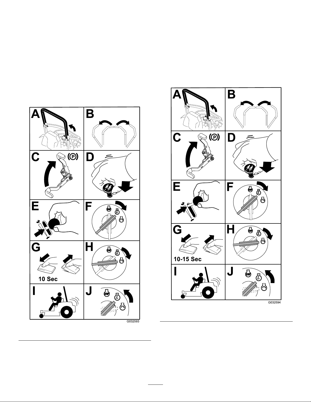
StartingandShuttingOff
theEngine
StartingtheEngineinNormal
Weather
Important:Usestartingcyclesofnomorethan
30secondsperminutetoavoidoverheatingthe
startermotor.
Note:Additionalstartingcyclesmayberequired
whenstartingtheengineforthersttimeafterthefuel
systemhasbeencompletelywithoutfuel.
StartingtheEngineinCold
Weather(Below23°For-5°C)
Usethecorrectengineoilforthestartingtemperature;
refertoEngine-OilSpecications(page46).
Important:Usestartingcyclesofnomorethan
30secondsperminutetoavoidoverheatingthe
startermotor.
Note:Donotusefuelleftoverfromthesummer.Use
onlyfreshwinter-gradedieselfuel.
Figure23
g032594
Figure24
g032593
26

ShuttingOfftheEngine
UsingtheMotion-Control
CAUTION
Childrenorbystandersmaybeinjuredifthey
moveorattempttooperatethemachinewhile
itisunattended.
Alwaysremovethekeyandengagethe
parkingbrakewhenleavingthemachine
unattended.
Levers
Figure25
Important:Makesurethatyouclosethe
fuel-shutoffvalvebeforetransportingorstoring
themachine,asfuelleakagemayoccur.Engage
theparkingbrakebeforetransportingthe
machine.Makesurethatyouremovethekeyas
thefuelpumpmayrunandcausethebatteryto
losecharge.
g004532
Figure26
1.Motion-control
lever—NEUTRAL-LOCK
position
2.Center,unlockedposition5.Frontofmachine
3.Forward
g032595
DrivingtheMachine
Thedrivewheelsturnindependently,poweredby
hydraulicmotorsoneachaxle.Youcanturn1side
inreversewhileyouturntheotherforward,causing
themachinetospinratherthanturn.Thisgreatly
improvesthemachinemaneuverabilitybutmay
requiresometimeforyoutoadapttohowitmoves.
Thethrottlecontrolregulatestheenginespeedas
measuredinrpm(revolutionsperminute).Place
thethrottlecontrolintheFASTpositionforbest
performance.Alwaysoperateinthefullthrottle
positionwhenmowing.
4.Backward
27

WARNING
Themachinecanspinveryrapidly.You
maylosecontrolofthemachineandcause
personalinjuryordamagetothemachine.
•Usecautionwhenmakingturns.
•Slowthemachinedownbeforemaking
sharpturns.
DrivingForward
Note:Theengineshutsoffwhenyoumovethe
traction-controlwiththeparkingbrakeengaged.
Tostopthemachine,pullthemotion-controllevers
totheNEUTRALposition.
1.Disengagetheparkingbrake;referto
DisengagingtheParkingBrake(page25).
2.Movetheleverstothecenter,unlockedposition.
3.T ogoforward,slowlypushthemotion-control
leversforward(Figure27).
DrivingBackward
1.Movetheleverstothecenter,unlockedposition.
2.T ogobackward,slowlypullthemotion-control
leversrearward(Figure28).
Figure27
g008953
Figure28
g008952
28

UsingtheSideDischarge
AdjustingtheHeightofCut
MachineswithSideDischarge
Only
Themowerhasahingedgrassdeectorthat
dispersesclippingstothesideanddowntowardthe
turf.
DANGER
Withoutagrassdeector,dischargecover,or
acompletegrass-catcherassemblymounted
inplace,youandothersareexposedtoblade
contactandthrowndebris.Contactwith
rotatingmowerblade(s)andthrowndebris
willcauseinjuryordeath.
•Neverremovethegrassdeectorfromthe
mowerdeckbecausethegrassdeector
routesmaterialdowntowardtheturf.Ifthe
grassdeectoriseverdamaged,replaceit
immediately.
•Neverputyourhandsorfeetunderthe
mowerdeck.
UsingtheTransportLock
Thetransportlockhas2positions,andisusedwith
thedeck-liftpedal.ThereisaLOCKpositionand
anUNLOCKpositionforthetransportpositionofthe
mowerdeck(Figure29).
•Nevertrytoclearthedischargearea
ormowerbladesunlessyoumovethe
blade-controlswitch(PTO)totheOFF
position,rotatethekeyswitchtotheOFF
position,andremovethekeyfromthekey
switch.
•Makesurethatthegrassdeectorisinthe
downposition.
g229103
Figure29
Transport-LockPositions
1.Transportlockknob3.UNLOCKposition—The
2.LOCKposition—The
mowerdecklocksintothe
transportposition.
29
mowerdeckdoesnotlock
intothetransportposition.

AdjustingtheHeight-of-CutPin
AdjustingtheAnti-Scalp
Theheight-of-cutisadjustedfrom25to140mm(1
to5-1/2inches)in6mm(1/4inch)incrementsby
relocatingtheclevispinintodifferentholelocations.
1.Movethetransportlocktothelockposition.
2.Pushonthedeck-liftpedalwithyourfoot,and
raisethemowerdecktothetransportposition
(alsothe140mm(5-1/2inch)cuttingheight
position)asshowninFigure30.
3.T oadjust,rotatethepin90degreesandremove
thepinfromtheheight-of-cutbracket(Figure
30).
4.Selectaholeintheheight-of-cutbracket
correspondingtotheheight-of-cutdesired,and
insertthepin(Figure30).
5.Pushonthedecklift,pullbackonthetransport
lock,andslowlylowerthemowerdeck.
Rollers
ForMachineswithSideDischarge
Wheneveryouchangetheheight-of-cut,adjustthe
heightoftheanti-scalprollers.
1.Parkthemachineonalevelsurface,disengage
theblade-controlswitch,andengagetheparking
brake.
2.Shutofftheengine,removethekey ,andwait
forallmovingpartstostopbeforeleavingthe
operatingposition.
3.Adjusttheanti-scalprollersasshowninFigure
31,Figure32,andFigure33.
1.Deck-liftpedal
2.Cut-of-heightpin
Figure30
3.Transportlock
g029955
Figure31
1.Anti-scalproller4.Flangenut
2.Spacer
3.Bushing
g027343
1.Anti-scalproller3.Flangenut
2.Bushing4.Bolt
5.Bolt
g029956
Figure32
30

Figure33
1.Anti-scalproller4.Flangenut
2.Spacer
3.Bushing
5.Bolt
AdjustingtheAnti-Scalp
Rollers
ForMachineswithRearDischarge
Wheneveryouchangetheheightofcut,itis
recommendedtoadjusttheheightoftheanti-scalp
rollers.
1.Parkthemachineonalevelsurface,disengage
theblade-controlswitch,andengagetheparking
brake.
2.Shutofftheengine,removethekey ,andwait
forallmovingpartstostopbeforeleavingthe
operatingposition.
g029957
g024242
Figure34
1.Flangenut3.Bushing
2.Anti-scalproller4.Bolt
3.Adjusttheanti-scalprollersasshowninFigure
34andFigure35.
g024243
Figure35
1.Bolt3.Anti-scalproller
2.Bushing4.Flangenut
31

AdjustingtheFlowBafe
PositioningtheFlowBafe
CamLocks
ForMachineswithSideDischarge
Thisprocedureisapplicableonlytomachineswiththe
ow-bafelocks.Certainmodelshavenutsandbolts
inplaceoftheow-bafelocksandcanbeadjusted
thesame.
Youcanadjustthemower-dischargeowfordifferent
typesofmowingconditions.Positionthecamlocks
andbafetogivethebestqualityofcut.
1.Parkthemachineonalevelsurface,disengage
theblade-controlswitch,andengagetheparking
brake.
2.Shutofftheengine,removethekey ,andwait
forallmovingpartstostopbeforeleavingthe
operatingposition.
3.T oadjustthecamlocks,swingtheleverupto
loosenthecamlock(Figure36).
4.Adjustthebafeandcamlocksintheslotsto
thedesireddischargeow.
5.Swingtheleverbackovertotightenthebafe
andcamlocks(Figure36).
ForMachineswithSideDischarge
Thefollowingguresareonlyrecommendations
foruse.Adjustmentsvarybygrasstype,moisture
content,andtheheightofthegrass.
Note:Iftheenginepowerdrawsdownandthe
mowergroundspeedisthesame,openupthebafe.
PositionA
Thisisthefullrearposition.Thesuggestedusefor
thispositionisasfollows:
•Short,lightgrassmowingconditions
•Dryconditions
•Smallergrassclippings
•Propelsgrassclippingsfartherawayfromthe
mower
6.Ifthecamlocksdonotlockthebafeintoplace
oritistootight,loosentheleverandthenrotate
thecamlock.
Note:Adjustthecamlockuntilthedesired
lockingpressureisachieved.
Figure36
g005832
Figure37
PositionB
Usethispositionwhenbagging.Alwaysalignitwith
thebloweropening.
g027727
g005833
Figure38
32

PositionC
OperatingwiththeOverheat
Thisisthefullopenposition.Thesuggestedusefor
thispositionisasfollows:
•Tall,densegrassmowingconditions
•Wetconditions
•Lowerstheengine-powerconsumption
•Allowsincreasedgroundspeedinheavyconditions
Figure39
Sensor
Thismachinehasasensorthatturnsoffthemower
deckwhentheengineoverheats.Whentheengine
overheats,theaudiblealarmandlightalarmturnson
alongwiththemowerdeckturningoff.
Ifthemowerdeckturnsoffautomaticallybecauseof
overheating,youwillbeabletodrivethemachineto
asafeareaortoatruckortrailer.
Ifthemachineoverheats,ensurethattheareaaround
theengineandradiatorisclearofanydebris.Shutoff
theengineandallowittocoolbeforeyouengagethe
mowerdeck.Iftheenginecontinuestooverheat,take
yourmachinetoanAuthorizedServiceDealer.
OperatingTips
UsingtheFastThrottleSetting
Forbestmowingandmaximumaircirculation,operate
theengineattheFASTposition.Airisrequiredto
thoroughlycutgrassclippings,sodonotsetthe
g005834
height-of-cutsolowastototallysurroundthemower
deckinuncutgrass.Alwaystrytohave1sideofthe
mowerdeckfreefromuncutgrass,whichallowsair
tobedrawnintothemowerdeck.
CuttingaLawnfortheFirstTime
Cutgrassslightlylongerthannormaltoensurethat
thecuttingheightofthemowerdeckdoesnotscalp
anyunevenground.However,thecuttingheight
usedinthepastisgenerallythebestonetouse.
Whencuttinggrasslongerthan15cm(6inches)tall,
youmaywanttocutthelawntwicetoensurean
acceptablequalityofcut.
CuttingaThirdoftheGrassBlade
Itisbesttocutonlyaboutathirdofthegrassblade.
Cuttingmorethanthatisnotrecommendedunless
grassissparse,oritislatefallwhengrassgrows
moreslowly.
AlternatingtheMowingDirection
Alternatethemowingdirectiontokeepthegrass
standingstraight.Thisalsohelpsdisperseclippings,
whichenhancesdecompositionandfertilization.
MowingatCorrectIntervals
Grassgrowsatdifferentratesatdifferenttimesof
theyear.Tomaintainthesamecuttingheight,mow
moreofteninearlyspring.Asthegrassgrowthrate
33

slowsinmidsummer,mowlessfrequently .Ifyou
cannotmowforanextendedperiod,rstmowata
highcuttingheight,thenmowagain2dayslaterata
lowerheightsetting.
AfterOperation
AfterOperationSafety
UsingaSlowerCuttingSpeed
Toimprovecutquality,useaslowergroundspeed
incertainconditions.
AvoidingCuttingTooLow
Whenmowinguneventurf,raisethecuttingheight
toavoidscalpingtheturf.
StoppingtheMachine
Ifyoumuststoptheforwardmotionofthemachine
whilemowing,aclumpofgrassclippingsmay
dropontoyourlawn.Toavoidthis,moveontoa
previouslycutareawiththebladesengagedoryou
candisengagethemowerdeckwhilemovingforward.
KeepingtheUndersideofthe
MowerDeckClean
Cleanclippingsanddirtfromtheundersideofthe
mowerdeckaftereachuse.Ifgrassanddirtbuildup
insidethemowerdeck,cuttingqualitywilleventually
becomeunsatisfactory.
GeneralSafety
•Cleangrassanddebrisfromthecuttingunits,
mufers,andenginecompartmenttohelpprevent
res.Cleanupoilorfuelspills.
•Shutoffthefuelandremovethekeybeforestoring
ortransportingthemachine.
•Disengagethedrivetotheattachmentwhenever
youaretransportingornotusingthemachine.
•Allowtheenginetocoolbeforestoringthemachine
inanyenclosure.
•Neverstorethemachineorfuelcontainerwhere
thereisanopename,spark,orpilotlight,such
asonawaterheateroronotherappliances.
UsingtheFuel-Shutoff
Valve
Thefuel-shutoffvalveislocatedundertheseat.Move
theseatforwardtoaccessit.
Closethefuel-shutoffvalvefortransport,maintenance,
andstorage.
MaintainingtheBlade(s)
Maintainasharpbladethroughoutthecuttingseason
becauseasharpbladecutscleanlywithouttearingor
shreddingthegrassblades.T earingandshredding
turnsgrassbrownattheedges,whichslowsgrowth
andincreasesthechanceofdisease.Checkthe
mowerbladesaftereachuseforsharpness,and
foranywearordamage.Filedownanynicksand
sharpenthebladesasnecessary .Ifabladeis
damagedorworn,replaceitimmediatelywitha
genuineT ororeplacementblade.
Ensurethatthefuel-shutoffvalveisopenwhen
startingtheengine.
g008948
Figure40
1.ONposition2.OFFposition
34

PushingtheMachineby
ChangingtoMachineOperation
Hand
Important:Alwayspushthemachinebyhand.
Nevertowthemachinebecausehydraulicdamage
mayoccur.
PushingtheMachine
1.Parkthemachineonalevelsurface,disengage
theblade-controlswitch,andengagetheparking
brake.
2.Shutofftheengine,removethekey ,andwait
forallmovingpartstostopbeforeleavingthe
operatingposition.
3.Rotatethebypassvalvescounterclockwise1
turntopush(Figure41).
Note:Thisallowshydraulicuidtobypassthe
pumpenablingthewheelstoturn.
Important:Donotrotatebypassvalves
morethan1turn.Thispreventsvalvesfrom
comingoutofthebodyandcausinguidto
runout.
4.Disengagetheparkingbrakebeforepushing.
Rotatethebypassvalvesclockwise1turntooperate
machine(Figure41).
Note:Donotover-tightenthebypassvalves.
Important:Themachinedoesnotdriveunless
bypassvalvesareturnedin.
Figure41
1.Sideconsolecontrols
2.Bypassvalve
3.Hydraulicpumps
g010371
TransportingtheMachine
Useaheavy-dutytrailerortrucktotransportthe
machine.Useafull-widthramp.Ensurethatthetrailer
ortruckhasallthenecessarybrakes,lighting,and
markingasrequiredbylaw.Pleasecarefullyreadall
thesafetyinstructions.Knowingthisinformationcould
helpyouorbystandersavoidinjury.Refertoyour
localordinancesfortrailerandtie-downrequirements.
WARNING
Drivingonthestreetorroadwaywithout
turnsignals,lights,reectivemarkings,ora
slow-moving-vehicleemblemisdangerous
andcanleadtoaccidents,causingpersonal
injury.
Donotdrivethemachineonapublicstreet
orroadway.
35

SelectingaTrailer
WARNING
Loadingamachineontoatrailerortruck
increasesthepossibilityoftip-overandcould
causeseriousinjuryordeath(Figure42).
•Useonlyafull-widthramp;donotuse
individualrampsforeachsideofthe
machine.
•Donotexceeda15-degreeanglebetween
therampandthegroundorbetweenthe
rampandthetrailerortruck.
•Ensurethatthelengthoftherampisat
least4timesaslongastheheightofthe
trailerortruckbedtotheground.This
ensuresthattherampangledoesnot
exceed15degreesonatground.
Figure42
1.Full-widthrampinstowed
position
2.Sideviewoffull-width
rampinloadingposition
3.Notgreaterthan
15degrees
4.Rampisatleast4times
aslongastheheightof
thetrailerortruckbedto
theground
5.H=heightofthetraileror
truckbedtotheground
6.Trailer
LoadingtheMachine
WARNING
Loadingamachineontoatrailerortruck
increasesthepossibilityoftip-overandcould
causeseriousinjuryordeath.
•Useextremecautionwhenoperatinga
machineonaramp.
•Backthemachineuptherampanddriveit
forwarddowntheramp.
g027996
•Avoidsuddenaccelerationordeceleration
whiledrivingthemachineonarampas
thiscouldcausealossofcontrolora
tip-oversituation.
36

1.Ifusingatrailer,connectittothetowingvehicle
andconnectthesafetychains.
2.Ifapplicable,connectthetrailerbrakesand
lights.
UsingtheZStand
TM
TheZStandraisesthefrontendofthemachineto
allowyoutocleanthemowerandremovetheblades.
3.Lowertheramp,ensuringthattheangle
betweentherampandthegrounddoesnot
exceed15degrees(Figure42).
4.Backthemachineuptheramp(Figure43).
Figure43
1.Backthemachineupthe
ramp.
2.Drivethemachineforward
downtheramp.
5.Shutofftheengine,removethekey,andengage
theparkingbrake.
6.Tiedownthemachinenearthefrontcaster
wheelsandtherearbumperwithstraps,chains,
cable,orropes(Figure44).Refertolocal
regulationsfortie-downrequirements.
WARNING
Themachinecouldfallontosomeoneand
causeseriousinjuryordeath.
•Useextremecautionwhenoperatingthe
machineontheZStand.
•UsetheZStandonlyforcleaningthe
mowerandremovingtheblades.
•DonotkeepthemachineontheZStand
forextendedperiodsoftime.
g028043
•Alwaysshutofftheengine,setthe
parkingbrake,andremovethekeybefore
performinganymaintenancetothemower.
DrivingupontotheZStand
Important:UsetheZStandonalevelsurface.
1.Raisethemowerdecktothetransportposition.
2.Removethebracketpin(Figure45).
Figure44
1.Tie-downloops
UnloadingtheMachine
1.Lowertheramp,ensuringthattheangle
betweentherampandthegrounddoesnot
exceed15degrees(Figure42).
2.Drivethemachineforwarddowntheramp
(Figure43).
g001811
Figure45
1.ZStand4.Bottomofslot
2.Bracketpin5.Latch
g028622
3.Bracket
3.Raisethelatch.
37

4.Swingthestandfootoutfrontandslideit
towardmachine,intothebottomofslot(Figure
45andFigure46).
Figure46
DrivingofftheZStand
1.Removethechocksorblocks.
2.Raisethelatchtotheunlockedposition(Figure
47).
g001812
1.ZStand(positionedinslot)
2.Crackinsidewalkorturf
3.Latchrestingonpivottab
5.Setthefootofthestandonthegroundandrest
thelatchonthepivottab(Figure46).
6.Starttheengineandputitathalfthrottle.
Note:Forbestresults,placethefootofthe
standintotheseamsinsidewalksorintotheturf
(Figure46).
7.Drivethemachineontothestand.Stopwhen
thelatchdropsoverthetabintothelocked
position(Figure46).
8.Engagetheparkingbrakeandturnoffthe
engine.
9.Chockorblockthedrivewheels.
WARNING
Theparkingbrakemaynotholdthe
machineparkedontheZStandand
couldcausepersonalinjuryorproperty
damage.
Figure47
1.ZStand
2.Latch4.Unlockedposition
3.Lockedposition
3.Starttheengineandplaceitathalfthrottle.
Disengagetheparkingbrake.
4.Slowlydrivebackwardoffthestand.
5.Returnthestandtoitsrestposition(Figure45).
g001813
DonotparkontheZStandunlessthe
wheelsarechockedorblocked.
10.Performthemaintenance.
38

Maintenance
Determinetheleftandrightsidesofthemachinefromthenormaloperatingposition.
RecommendedMaintenanceSchedule(s)
MaintenanceService
Interval
Aftertherst8hours
Aftertherst25hours
Aftertherst50hours
Aftertherst100hours
Beforeeachuseordaily
Every25hours
MaintenanceProcedure
•Checktheenginecoolingsystemlevel.
•Checkthehydraulicuid.
•Changethehydrauliclter.
•Replacetheengineoil.
•Changetheengine-oillter.
•Changetheengineoil.
•Checkthewheel-hubslottednut.
•Changethegearboxoil.
•Checkthesafetysystem.
•Checktheengine-oillevel.
•Checktheenginecoolingsystemlevel.
•Cleantheengine-oilcooler.
•Inspecttheblades.
•Cleanthemowerdeck.
•Greasethemowerdeckandspindles.
•Greasethemowerbeltidlerarm.
•Greasethepumpbeltidlerarm.
•GreasethePTO-drivebeltidlerarm.
•Greasethebrakelever .
•Checkthehydraulicuid.
Every40hours
Every50hours
Every100hours
Every150hours
Every200hours
Every250hours
Every400hours
•Drainthewaterseparator.
•Checkthetirepressure
•CheckthePTO-drivebelt.
•Checkthepumpdrivebelt.
•Checkthealternatorbelt.
•Lubricatethedeck-liftpivots.
•Replacetheengineoil.
•Changetheengineoil.
•Checkthegearbox-oillevel.
•Checktheenginecoolingsystemhoses.
•Inspectthebeltsforcracksandwear.
•Checkthehydraulichoses.
•Addlightoilorspraylubricationtothemachine;refertolubrication.
•Changetheengine-oillter.
•Greasethebrakepivot.
•Checkand/orreplacetheairlter(moreoftenindirtyordustyconditions).
•ChangethehydrauliclterandhydraulicuidwhenusingMobil®1uid.
•Replacethefuellter(moreoftenindirtyordustyconditions).
39

MaintenanceService
Interval
Every500hours
Yearly
MaintenanceProcedure
•Checkthewheel-hubslottednut.
•Adjustthecaster-pivotbearing.
•Adjusttheelectricclutch.
•ChangethehydrauliclterandhydraulicuidwhenusingToro®HYPR-OIL™500
hydraulicuid.
•Greasethefrontcasterpivots(moreoftenindirtyordustyconditions).
•Lubricatethecaster-wheelhubs.
•Changethegearboxoil.
•Changetheenginecoolant.
Important:Refertoyourengineowner'smanualforadditionalmaintenanceprocedures.
CAUTION
Ifyouleavethekeyintheswitch,someonecouldaccidentlystarttheengineandseriously
injureyouorotherbystanders.
Removethekeyfromtheswitchbeforeyouperformanymaintenance.
Pre-Maintenance
Procedures
MaintenanceSafety
•Beforerepairingthemachinedothefollowing:
–Disengagethedrives.
–Engagetheparkingbrake.
–Shutofftheengineandremovethekey .
–Disconnectthespark-plugwire.
•Parkthemachineonalevelsurface.
•Cleangrassanddebrisfromthecuttingunit,
drives,mufers,andenginetohelppreventres.
•Cleanupoilorfuelspills.
•Donotallowuntrainedpersonneltoservicethe
machine.
•Usejackstandstosupportthemachineand/or
componentswhenrequired.
•Carefullyreleasepressurefromcomponentswith
storedenergy.
•Disconnectthebatteryorremovethespark-plug
wirebeforemakinganyrepairs.Disconnectthe
negativeterminalrstandthepositiveterminal
last.Connectthepositiveterminalrstand
negativelast.
•Usecarewhencheckingtheblades.Wrapthe
blade(s)orwearthicklypaddedgloves,anduse
cautionwhenservicingthem.Onlyreplaceblades;
donotstraightenorweldthem.
•Keepyourhandsandfeetawayfrommoving
parts.Ifpossible,donotmakeadjustmentswith
theenginerunning.
•Keepallpartsingoodworkingcondition
andallhardwaretightened,especiallythe
blade-attachmentbolts.Replaceallwornor
damageddecals.
•Neverinterferewiththeintendedfunctionofa
safetydeviceorreducetheprotectionprovided
byasafetydevice.Checktheirproperoperation
regularly.
•UseonlygenuineT ororeplacementparts.
•Checktheparkingbrakeoperationfrequently.
Adjustandserviceasrequired.
40

ReleasingtheMower-Deck
Curtain
Lubrication
Loosenthebottomboltofthecurtaintorelease
themower-deckcurtainandgetaccesstothetop
ofthemowerdeck(Figure48).Afterperforming
maintenance,installthecurtainandtightenthebolt.
Figure48
1.Bolt
2.Curtain
GreasingtheMachine
Greasemorefrequentlywhenoperatingconditions
areextremelydustyorsandy .
GreaseType:No.2lithiumormolybdenumgrease
1.Parkthemachineonalevelsurface,disengage
theblade-controlswitch,andengagetheparking
brake.
2.Shutofftheengine,removethekey ,andwait
forallmovingpartstostopbeforeleavingthe
operatingposition.
3.Cleanthegreasettingswitharag.
Note:Makesurethatyouscrapeanypaintoff
thefrontofthetting(s).
4.Connectagreaseguntothetting.
g027945
5.Pumpgreaseintothettingsuntilgreasebegins
tooozeoutofthebearings.
6.Wipeupanyexcessgrease.
RemovingtheSheet-Metal
Guard
Loosenthe2frontboltsandremovethesheet-metal
guardtoaccessthemowerbeltsandspindles
(Figure49).Afterperformingmaintenance,installthe
sheet-metalguardandtightenthebolts.
GreasingtheFrontCaster
Pivots
ServiceInterval:Yearly(moreoftenindirtyordusty
conditions).
1.Removethedustcapandadjustthecaster
pivotsandkeepthedustcapoffuntilgreasingis
done;refertoAdjustingtheCaster-PivotBearing
(page55).
2.Removethehexplug.
3.Threadagreasettingintothehole.
4.Pumpgreaseintothettinguntilitoozesout
aroundthetopbearing.
5.Removethegreasettingfromthehole.Install
thehexplugandcap.
AddingGrease
LubricatethegreasettingsasshownontheCheck
ServiceReferenceAiddecal(Figure50orFigure51).
1.Sheet-metalguard
g027946
Figure49
2.Bolt
41

SideDischargeMachines
AddingLightOilorSpray
Lubrication
SideDischargeMachines
ServiceInterval:Every100hours
Lubricatethedeck-liftpivots.
decal136-5510
Figure50
g017028
Figure52
RearDischargeMachines
AddingLightOilorSpray
Lubrication
RearDischargeMachines
ServiceInterval:Every150hours
Lubricatethemachineinthefollowingareaswith
spraytypelubricantorlightoil.
•Seat-switchactuator
•Brake-handlepivot
•Brake-rodbushings
•Motioncontrolbronzebushings
decal136-5519
Figure51
42

GreasingtheMowerDeck
andBeltIdlers
ServiceInterval:Every25hours—Greasethemower
deckandspindles.
GreasewithNo.2lithiumormolybdenumgrease.
Important:Makesurethatthecutting-unit
spindlesarefullofgreaseweekly.
1.Parkthemachineonalevelsurface,disengage
theblade-controlswitch,andengagetheparking
brake.
2.Shutofftheengine,removethekey ,andwait
forallmovingpartstostopbeforeleavingthe
operatingposition.
3.Loosenthebottomboltholdingthemower-deck
curtaintothemowerdeck;refertoReleasing
theMower-DeckCurtain(page41).
4.Removethesheet-metalguard;referto
RemovingtheSheet-MetalGuard(page41)
5.Removethebeltcovers.
6.Greasetheidlerarmonthemowerdeck(Figure
53).
7.Greasethettingsonthepusharms(Figure53
orFigure54).
g194085
Figure54
RearDischargeMachines
8.GreasethePTO-drivebeltidlerarm(Figure55).
9.Greasethepumpbeltidlerarm(Figure55).
SideDischargeMachines
g007170
Figure55
10.Installthesheet-metalguard.
11.Tightenthebottomboltholdingthemower-deck
curtaintothemowerdeck.
g187362
Figure53
43

Lubricatingthe
Caster-WheelHubs
ServiceInterval:Yearly
1.Parkthemachineonalevelsurface,disengage
theblade-controlswitch,andengagetheparking
brake.
2.Shutofftheengine,removethekey ,andwait
forallmovingpartstostopbeforeleavingthe
operatingposition.
12.Inserttheassemblednutandaxleintothewheel
onthesideofthewheelwiththenewsealand
bearing.
13.Withtheopenendofthewheelfacingup,ll
theareainsidethewheelaroundtheaxlefullof
general-purposegrease.
14.Insertthesecondbearingandnewsealintothe
wheel.
15.Applyathread-lockingadhesivetothesecond
spacernut,andthreaditontotheaxlewiththe
wrenchatsfacingoutward.
16.T orquethenutto8to9N∙m(75to80in-lb),
loosen,thentorqueto2to3N∙m(20to25in-lb).
Note:Makesurethattheaxledoesnotextend
beyondeithernut.
17.Installthesealguardsoverthewheelhub,and
insertthewheelintothecasterfork.
18.Installthecasterboltandtightenthenutfully.
Figure56
1.Sealguard2.Spacernutwithwrench
ats
3.Raisethemowerforaccess.
4.Removethecasterwheelfromthecasterforks.
5.Removethesealguardsfromthewheelhub.
6.Removeaspacernutfromtheaxleassemblyin
thecasterwheel.
Note:Thread-lockingadhesivehasbeen
appliedtolockthespacernutstotheaxle.
7.Removetheaxle(withtheotherspacernutstill
assembledtoit)fromthewheelassembly.
8.Pryoutsealsandinspectbearingsforwearor
damageandreplaceifnecessary.
9.Packthebearingswithageneral-purpose
grease.
10.Insert1bearingand1newsealintothewheel.
g006115
Important:Topreventsealandbearingdamage,
checkthebearingadjustmentoften.Spinthe
castertire.Thetireshouldnotspinfreely(more
than1or2revolutions)orhaveanysideplay.If
thewheelspinsfreely,adjustthetorqueonthe
spacernutuntilthereisaslightamountofdrag.
Applyanotherlayerofthread-lockingadhesive.
Note:Replacetheseals.
11.Iftheaxleassemblyismissingbothspacernuts,
applyathread-lockingadhesiveto1spacernut
andthreaditontotheaxlewiththewrenchats
facingoutward.
Note:Donotthreadthespacernutallof
thewayontotheendoftheaxle.Leave
approximately3mm(1/8inch)fromtheouter
surfaceofthespacernuttotheendoftheaxle
insidethenut.
44

EngineMaintenance
EngineSafety
•Shutofftheengineandremovethekeybefore
checkingtheoiloraddingoiltothecrankcase.
•Keepyourhands,feet,face,clothing,andother
bodypartsawaythemuferandotherhotsurfaces.
ServicingtheAirCleaner
Note:Checktheltersmorefrequentlyifoperating
conditionsareextremelydustyorsandy.
RemovingtheAirFilter
ServiceInterval:Every250hours(moreoftenindirty
ordustyconditions).
1.Parkthemachineonalevelsurface,disengage
theblade-controlswitch,andengagetheparking
brake.
2.Shutofftheengine,removethekey ,andwait
forallmovingpartstostopbeforeleavingthe
operatingposition.
3.Releasethelatchesontheaircleanerandpull
theair-cleanercoverofftheair-cleanerbody
(Figure57).
4.Cleantheinsideoftheair-cleanercoverwith
compressedair.
5.Gentlyslidethelteroutoftheair-cleanerbody
(Figure57).
Note:Avoidknockingthelterintothesideof
thebody.
6.Inspectthelterfordamagebylookingintothe
lterwhileshiningabrightlightontheoutside
ofthelter.
Note:Holesinthelterappearasbrightspots.
Ifthelterisdamaged,discardit.
Figure57
1.Air-lterbody
2.Airlter
3.Air-cleanercover
4.Latches
InstallingtheAirFilter
1.Ifinstallinganewlter,checkthelterfor
shippingdamage.Donotuseadamagedlter.
2.Carefullyslidethelterintothelterbody
(Figure58).
Note:Ensurethatitisfullyseatedbypushing
ontheouterrimofthelterwhileinstallingit.
Important:Donotpressonthesoftinside
areaofthelter.
3.Installtheair-cleanercoverandsecurethe
latches(Figure58).
g001049
45

Figure58
1.Air-lterbody
2.Airlter
3.Air-cleanercover
4.Latches
ServicingtheEngineOil
Engine-OilSpecications
OilType:High-qualitydetergentoilclassiedAPI
ServiceCJ-4orhigherfordieselengines.Donotuse
specialadditiveswithrecommendedoils.
g001061
Figure59
PreparingtoServicetheEngine
Oil
Important:Thefastenersforthefrontengine
g001048
panelaredesignedtoremainonthemachineafter
coverremoval.Loosenallofthefastenersafew
turnssothatthepanelisloosebutstillattached,
thengobackandloosenthemuntilthepanel
comesfree.Thispreventsyoufromaccidentally
strippingtheboltsfreeoftheretainers.
Tilttheseatforward,loosentheboltsholdingthefront
enginepanelandremoveit(Figure60).
CrankcaseCapacity:3.7L(3.9USqt)
Viscosity:Seethetablebelow.
g012347
Figure60
1.Bolt2.Frontenginepanel
Note:Afterservicingtheengineoil,installtheengine
panelandtilttheseatintoitsuprightposition.
46

CheckingtheEngine-OilLevel
ServiceInterval:Beforeeachuseordaily
Note:Checktheoilwhentheengineiscold.
1.Parkthemachineonalevelsurface,disengage
theblade-controlswitch,andengagetheparking
brake.
2.Shutofftheengine,removethekey ,andwait
forallmovingpartstostopbeforeleavingthe
operatingposition.
3.Checktheengine-oillevel(Figure61).
Important:Addtheoilveryslowlyand
donotblocktheopeningofthellerhole
(Figure40).Ifyouaddoiltoofastorblock
thehole,theoilcouldbackupandfoulthe
airintakes,causingenginedamage.
g000955
Figure62
1.Notetheclearanceleftinthelleropening.
Figure61
g032601
DrainingtheEngineOil
ServiceInterval:Aftertherst50hours
Every100hours
1.Starttheengineandletitrunfor5minutes.
Note:Thiswarmstheoilsoitdrainsbetter.
2.Parkthemachineonalevelsurface,disengage
theblade-controlswitch(PTO),movethe
motion-controlleverstotheNEUTRAL-LOCK
position,andengagetheparkingbrake.
3.Shutofftheengine,removethekey ,andwait
forallmovingpartstostopbeforeleavingthe
operatingposition.
g032641
4.Starttheengine,runitatidlefor5minutes,
shutofftheengine,waitfor3minutes,andthen
checktheengine-oillevel.Ifneeded,addoilup
totheFULLmarkonthedipstick.
Important:Besuretokeeptheengine-oil
levelbetweentheupperandlowerlimitson
theoilgauge.Enginefailuremayoccuras
aresult.
47

ChangingtheEngine-OilFilter
ServiceInterval:Aftertherst50hours
Every200hours
1.Draintheoilfromtheengine;refertoDraining
theEngineOil(page47).
2.Changetheengine-oillter(Figure64).
g032646
g032649
Figure63
Note:Disposeoftheusedoilatarecycling
center.
g032642
g032644
Figure64
3.Addoil;refertoChangingtheEngineOil(page
49).
48

ChangingtheEngineOil
AddingEngineOil
ServiceInterval:Aftertherst50hours
Every100hours
1.Starttheengineandletitrunfor5minutes.
Note:Thiswarmstheoilsoitdrainsbetter.
2.Parkthemachineonalevelsurface.
3.Disengagetheblade-controlswitch(PTO),move
themotion-controlleverstotheNEUTRAL-LOCK
position,andengagetheparkingbrake.
4.Shutofftheengine,removethekey ,andwait
forallmovingpartstostopbeforeleavingthe
operatingposition.
5.Placeapanbelowtheoildrain.Removethe
drainplugandlettheoildraincompletely(Figure
65).
6.Removetheoilllercapfromthetopofthe
engine(Figure67).
Note:Thishelpstheoiltodrain.
7.Installthedrainplugandtightenitto35N∙m
(25-1/2ft-lb).
1.Tilttheseatforwardandremovethefrontengine
panel(Figure66).
g001312
Figure66
1.Knob2.Frontenginepanel
Note:Disposeoftheusedoilatarecycling
center.
1.Backofthemachine
Figure65
2.Drainplug
2.Removetheoil-llcapanddipstick(Figure67).
g001162
Figure67
1.Engine
g001058
2.Oil-llcap
3.Useahoseandfunneltoaddoiltotheengine
(Figure68).
4.Addoilslowly,checkingthelevelfrequentlywith
thedipstickuntilthelevelreachestheupper
holeonthedipstick.Forthecorrectoiltype
andviscositytouseindifferenttemperature
conditions,refertoServicingtheEngineOil
(page46).
49

FuelSystem
Maintenance
WARNING
Fuel-systemcomponentsareunderhigh
pressure.Theuseofimpropercomponents
canresultinsystemfailure,fuelleakage,and
possibleexplosion.
Useonlyapprovedfuellinesandfuellters.
ServicingtheFuelFilter
Figure68
1.Engineoil2.Funnelandhose
Important:Addtheoilveryslowlyand
donotblocktheopeningofthellerhole
(Figure69).Ifyouaddoiltoofastorblock
thehole,theoilcouldbackupandfoulthe
airintakes,causingenginedamage.
Figure69
1.Notetheclearanceleftinthelleropening.
g001163
andWaterSeperator
ServiceInterval:Every40hours—Drainthewater
separator.
Every400hours/Y early(whichevercomes
rst)—Replacethefuellter(moreoftenindirty
ordustyconditions).
DrainingtheWaterSeparator
1.Parkthemachineonalevelsurface,disengage
theblade-controlswitch,andengagetheparking
brake.
2.Shutofftheengine,removethekey ,andwait
forallmovingpartstostopbeforeleavingthe
operatingposition.
3.Locatethewaterseparatoratthebackleftof
themachine.
4.Placeadrainpanbelowthewaterseparator.
g000955
5.Openthedrainvalveonthewaterseparator
approximately1turntoallowwaterandother
contaminatestodrain(Figure70).
5.Replacethedipstickandinstallthefrontengine
panel.
6.Starttheengineandrunitatidlefor5minutes.
7.Shutofftheengine.
8.Wait3minutesandchecktheoillevel.
9.Addoil,ifrequired,tobringtheleveltotheupper
holeonthedipstick.
10.Replacethedipstick,llercap,andthefront
enginepanel.
11.Checkforleaks.
Important:Donotoverllthecrankcase
withoilbecausethismaycauseengine
damage.
6.Closethedrainvalvewhenonlydieselfuel
comesout(Figure70).
50

Figure70
g007169
1.Drainvalve
2.Waterseparator
3.Backofmachine
ChangingtheFuelFilter
Neverinstalladirtyfuellterifitisremovedfromthe
fuelline.
1.Allowthemachinetocooldown.
2.Parkthemachineonalevelsurface,disengage
theblade-controlswitch,andengagetheparking
brake.
3.Shutofftheengine,removethekey ,andwait
forallmovingpartstostopbeforeleavingthe
operatingposition.
4.Closethefuelshut-offvalve(Figure71).
5.Loosenthe2hoseclampsanddisconnectthe
fuellinesfromthefuellter(Figure71).
6.Installanewlter.Connectthefuellinestothe
fuellterandinstallthe2hoseclamps(Figure
71).
Figure71
1.Fuellter4.Leftsideofmachine
2.Hoseclamp
3.Fuelpump
5.Fuel-shutoffvalve
ServicingtheFuelTank
Donotattempttodrainthefueltank.Ensurethatan
AuthorizedServiceDealerdrainsthefueltankand
servicesanycomponentsofthefuelsystem.
g007697
7.Openthefuelshut-offvalve.
8.Starttheengineandcheckforleaks.
51

ElectricalSystem
Maintenance
ElectricalSystemSafety
•Disconnectthebatterybeforerepairingthe
machine.Disconnectthenegativeterminalrst
andthepositivelast.Connectthepositiveterminal
rstandthenegativelast.
•Chargethebatteryinanopen,well-ventilated
area,awayfromsparksandames.Unplugthe
chargerbeforeconnectingordisconnectingthe
battery.Wearprotectiveclothinganduseinsulated
tools.
ServicingtheBattery
RemovingtheBattery
WARNING
3.Unlatchtheseatandtilttheseatup.
4.RemovethebatteryasshowninFigure72.
Batteryterminalsormetaltoolscouldshort
againstmetalmachinecomponents,causing
sparks.Sparkscancausethebatterygasses
toexplode,resultinginpersonalinjury.
•Whenremovingorinstallingthebattery,
donotallowthebatteryterminalstotouch
anymetalpartsofthemachine.
•Donotallowmetaltoolstoshortbetween
thebatteryterminalsandmetalpartsofthe
machine.
WARNING
Incorrectlyremovingthecablesfrombattery
coulddamagethemachineandcables,
causingsparks.Sparkscancausethebattery
gassestoexplode,resultinginpersonal
injury.
•Alwaysdisconnectthenegative(black)
batterycablebeforedisconnectingthe
positive(red)cable.
g032750
Figure72
•Alwaysconnectthepositive(red)battery
cablebeforeconnectingthenegative
(black)cable.
1.Parkthemachineonalevelsurface,disengage
theblade-controlswitch,andengagetheparking
brake.
2.Shutofftheengine,removethekey ,andwait
forallmovingpartstostopbeforeleavingthe
operatingposition.
52

InstallingtheBattery
Note:Positionthebatteryinthetraywiththeterminal
postsoppositefromthehydraulictank.
g000960
Figure74
Figure73
ChargingtheBattery
Important:Alwayskeepthebatteryfullycharged
(1.265specicgravity).Thisisespecially
importanttopreventbatterydamagewhenthe
temperatureisbelow0°C(32°F).
1.Makesurethatthellercapsareinstalledin
battery.Chargebatteryfor10to15minutesat
25to30Aor30minutesat10A.
1.Positivebatterypost
2.Negativebatterypost
3.Red(+)chargerlead
4.Black(-)chargerlead
ServicingtheFuses
Theelectricalsystemisprotectedbyfuses.Itrequires
nomaintenance,however,ifafuseblowscheck
component/circuitformalfunctionorshort.
1.Unlatchtheenginehoodandraisetheengine
g032751
hoodtogainaccesstofuseholder(Figure75).
2.T oreplacethefuses,pulloutonthefuseto
removeit.
3.Installanewfuse(Figure75).
2.Whenthebatteryisfullycharged,unplug
thechargerfromtheelectricaloutlet,then
disconnectthechargerleadsfromthebattery
posts(Figure74).
3.Installthebatteryinthemachineandconnect
thebatterycables,refertoInstallingtheBattery
(page53).
Note:Donotrunthemachinewiththebattery
disconnected,electricaldamagemayoccur.
Figure75
1.Ignition—30A(F1)3.Clutch—10A(F3)
2.Radiatorfan—50A(large,
heavydutyfuse)
53
4.Leftfueltank
g012492

DriveSystem
Maintenance
AdjustingtheTracking
Themachinehasaknobforadjustingthetracking
locatedundertheseat.
Important:Adjustthehandleneutraland
hydraulicpumpneutralbeforeadjustingthe
tracking;refertoAdjustingtheControlHandle
NeutralPosition(page64)andSettingthe
HydraulicPumpNeutralPosition(page68).
1.Pushbothcontrolleversforwardthesame
distance.
2.Checkifthemachinepullsto1side.Ifitdoes,
shutoffthemachineandengagetheparking
brake.
3.Unlatchtheseatandtilttheseatforwardto
accessthetrackingknob.
Note:Determinetheleftandrightsidesofthe
machinefromthenormaloperatingposition.
4.T omakethemachinegoright,turntheknob
towardtherightofthemachine;refertoFigure
76.
5.T omakethemachinegoleft,turntheknob
towardtheleftofthemachine;refertoFigure76.
6.Repeatadjustmentuntilthetrackingiscorrect.
Figure76
1.Trackingknob4.Turnthiswaytotrackright.
2.Hydraulictank
3.Hydraulicpumps
5.Turnthiswaytotrackleft.
CheckingtheTirePressure
ServiceInterval:Every50hours/Monthly(whichever
comesrst)
Maintaintheairpressureinthereartiresat90kPa
(13psi).Uneventirepressurecancauseunevencut.
Checkthetireswhentheyarecoldtogetthemost
accuratepressurereading.
Note:Thefronttiresaresemi-pneumatictiresanddo
notrequireairpressuremaintenance.
g001070
g001055
Figure77
54

CheckingtheWheel-Hub
SlottedNut
ServiceInterval:Aftertherst100hours—Checkthe
wheel-hubslottednut.
Every500hours—Checkthewheel-hubslotted
nut.
Torquetheslottlednutto286to352N∙m(211to260
ft-lb).
Note:Donotuseanti-seizecompoundonthewheel
hub.
AdjustingtheCaster-Pivot
Bearing
ServiceInterval:Every500hours/Yearly(whichever
comesrst)
1.Parkthemachineonalevelsurface,disengage
theblade-controlswitch,andengagetheparking
brake.
2.Shutofftheengine,removethekey ,andwait
forallmovingpartstostopbeforeleavingthe
operatingposition.
3.Removethedustcapfromcasterandtighten
thelocknut(Figure78).
4.Tightenthelocknutuntilthespringwashersare
at,andthenbackoffa1/4turntoproperlyset
thepreloadonthebearings(Figure78).
Important:Makesurethatthespring
washersareinstalledcorrectlyasshownin
Figure78.
5.Installthedustcap(Figure78).
Figure78
1.Springwashers
2.Locknut
3.Dustcap
ServicingtheGearbox
CheckingtheGearbox-OilLevel
ServiceInterval:Every100hours
UseSAE75W-90syntheticgearlube.
1.Parkthemachineonalevelsurface,disengage
theblade-controlswitch,andengagetheparking
brake.
2.Shutofftheengine,removethekey ,andwait
forallmovingpartstostopbeforeleavingthe
operatingposition.
3.Removethesideorrearplugonthegearbox
(Figure79).
g001297
4.Theoilshouldbeuptotheopeningofthe
gearbox.
5.Addoilifneededtobringittothecorrectlevel.
55

Figure79
AdjustingtheElectric
Clutch
ServiceInterval:Every500hours
Theclutchisadjustabletoensureproperengagement
andproperbraking.
1.Parkthemachineonalevelsurface,disengage
theblade-controlswitch,andengagetheparking
brake.
2.Shutofftheengine,removethekey ,andwait
forallmovingpartstostopbeforeleavingthe
operatingposition.
3.Unlatchtheseatandtipitforward.
4.Loosenthefrontenginepanelknobsand
removethepanel.
5.Pulluponthespring-loadedidlerpulleyforthe
PTO-drivebeltandremovethebeltfromthe
clutchpulley(Figure80).
g001156
1.Gearbox
2.Sideplug
3.Pulley
4.Rearplug
ChangingtheGearboxOil
ServiceInterval:Aftertherst100hours
Yearly
ContactanAuthorizedServiceDealertochangethe
gearboxoil.
g007167
Figure80
1.Spring-loadedidlerpulley3.PTO-drivebelt
2.Clutch4.Gearbox
6.Unplugtheelectricconnectionfortheclutch
(Figure81).
7.Removethe2boltsholdingtherubberclutch
straptothemowerframe(Figure81).
8.Removethecenterboltholdingtheclutchto
theengineshaftandremovetheclutchandkey
(Figure81).
56

Figure81
1.Clutch4.Clutchcenterbolt
2.2boltsandnutsforclutch
strap
3.Rubberclutchstrap
5.Electricalconnection
9.Inserta0.381to0.533mm(0.015to0.021inch)
feelergaugethroughaninspectionslotinthe
sideoftheassembly(Figure82).
16.Installtherubberclutchstraptothemower
framewiththe2previouslyremovedboltsand
nuts(Figure81).
17.Pulluponthespring-loadedidlerforthe
PTO-drivebeltandinstallitontotheclutch
pulley(Figure80).
18.Plugintheelectricconnectionfortheclutch
(Figure81).
19.Installthefrontenginepanelandtightenthe
knobs.
20.Lowerdowntheseat.
g007166
Note:Makesurethatitisbetweenthearmature
andtherotorfrictionsurfaces.
10.Tightenthelocknutsuntilthereisslightbinding
onthefeelergaugebutitcanbemovedeasily
withintheairgap(Figure82).
11.Repeatthisfortheremainingslots.
12.Checkeachslotagainandmakeslight
adjustmentsuntilthefeelergaugebetween
therotorandarmaturehasveryslightcontact
betweenthem.
Figure82
1.Slot
2.Adjustingnut
3.Feelergauge
g007168
13.Installtheclutchtotheengineshaftwiththekey.
14.Applythread-lockingadhesivetothecenterbolt.
15.Whileholdingthecrankshaftatthebackofthe
machine,installthecenterboltandtorqueitto
68N∙m(50ft-lb)(Figure81).
57

CoolingSystem
Note:Donotopentheradiatorcap.Doingthismay
induceairintothecoolingsystem.
Maintenance
ServicingtheCooling
System
DANGER
Dischargeofhotpressurizedcoolantor
touchinghotradiatorandsurroundingparts
cancausesevereburns.
•Donotremovetheradiatorcapwhenthe
engineishot.Alwaysallowtheengineto
coolatleast15minutesoruntiltheradiator
capiscoolenoughtotouchwithout
burningyourhandbeforeremovingthe
radiatorcap.
•Donottouchtheradiatorandsurrounding
partsthatarehot.
1.Positionthemachineonalevelsurface,shutoff
theengine,andengagetheparkingbrake.
2.Unlatchtheseatandtilttheseatup.
3.Withtheenginecool,checktheoverowbottle
level.Theuidneedstobeuptothebumpon
theoutsideoftheoverowbottle(Figure83).
4.Ifthecoolantlevelislow,adda50/50mixof
extendedlifeantifreeze/Dex-Cool®andwaterto
theoverowbottle(Figure83).
5.Addthe50/50coolantmixtotheoverowbottle
andllittotheindicatorlineonthebottle(Figure
83).
DANGER
Therotatingshaftandfancancausepersonal
injury.
•Donotoperatethemachinewithoutthe
coversinplace.
•Keepyourngers,hands,andclothing
clearofrotatingfananddriveshaft.
•Shutofftheengineandremovetheignition
keybeforeperformingmaintenance.
CAUTION
Swallowingenginecoolantcancause
poisoning.
•Donotswallowenginecoolant.
•Keepoutofreachfromchildrenandpets.
CheckingtheRadiatorCoolant
ServiceInterval:Beforeeachuseordaily
g001103
Figure83
1.Antifreezeoverowbottle2.Indicatorlineonsideof
overowbottle
Aftertherst8hours
Every100hours
FluidType:50/50mixofextendedlife
antifreeze/Dex-Cool®andwater
CoolingSystemCapacity:4.6L(156oz)
58

CleaningtheHydraulic-Fluid
CoolerandRadiatorScreen
BrakeMaintenance
ServiceInterval:Beforeeachuseordaily
Beforeeachuse,checkandcleantheradiatorscreen
andoilcooler.Removeanybuildupofgrass,dirtor
otherdebrisfromtheoilcoolerandradiatorscreen
withcompressedair(Figure84).
AdjustingtheParking
Brake
ServiceInterval:Every25hours
Every200hours
1.Engagetheparkingbrake.
2.Measurethelengthofthespring(Figure85).
Note:Themeasurementshouldbe64mm
(2-1/2inches)betweenthewashers.
3.Ifadjustmentisnecessary,disengagethe
parkingbrake,loosenthejamnutbelowthe
springandadjustthenutdirectlybelowthe
spring(Figure85).
4.Turnthenutuntilthecorrectmeasurementis
obtained.
Note:Turnthenutclockwisetoshortenspring
lengthandturncounter-clockwisetolengthen
thespring.
5.Tightenthe2nutstogether.
Figure84
1.Hydraulic-uidcooler
2.Leftreartire
3.Radiatorscreen
ChangingtheEngineCoolant
ServiceInterval:Yearly
ContactanAuthorizedServiceDealerforchanging
thecoolant.
6.Engagetheparkingbrakeandcheckthe
g001104
measurementofthespringagain.
7.Ifanadjustmentisnecessary ,repeatthe
proceduresabove.
8.Repeatontheoppositesideofmachine.
Figure85
1.Brakeleverinengaged
position
2.Spring—64mm(2-1/2
inches)
3.Adjustingnutandjamnut
g001294
59

BeltMaintenance
InspectingtheBelts
ServiceInterval:Every100hours
Checkthebeltsforsquealingwhenthebeltisrotating,
bladesslippingwhencuttinggrass,frayedbeltedges,
burnmarksandcracksaresignsofawornmower
belt.Replacethemowerbeltifanyoftheseconditions
areevident.
ReplacingtheMowerBelt
SideDischargeMachines
Squealingwhenthebeltisrotating,bladesslipping
whencuttinggrass,frayedbeltedges,burnmarks
andcracksaresignsofawornmowerbelt.Replace
themowerbeltifanyoftheseconditionsareevident.
1.Parkthemachineonalevelsurface,disengage
theblade-controlswitch,andengagetheparking
brake.
2.Shutofftheengine,removethekey ,andwait
forallmovingpartstostopbeforeleavingthe
operatingposition.
3.Loosenthebottomboltholdingthemower-deck
curtaintothemowerdeck;refertoReleasing
theMower-DeckCurtain(page41).
4.Removethesheet-metalguard;referto
RemovingtheSheet-MetalGuard(page41).
5.Removethebeltcovers(Figure86).
7.Removethebeltguideonthespring-loaded
idlerpulleyshowninFigure87.
8.Removetheexistingbelt.
9.Installthenewbeltaroundthemowerpulleys
andthegearboxpulleyundertheengine(Figure
87).
Figure87
1.Mowerbelt
2.Mowerspindlepulley6.Idlerspring
3.Spring-loadedidlerpulley7.Idlerplate(for72-inch
4.Beltguideata45degree
angle
10.Installthebeltguideonthespring-loadedidler
ata45degreeangleasshowninFigure87.
Torquetheboltto37to45N∙m(27to33ft-lb).
5.Gearboxpulley
mowersonly)
g006479
Figure86
1.Beltcover3.Insertslotintothetab
2.Latch
6.Removetheidlerspring.
11.Installtheidlerspringtothe2posts(Figure87).
12.Installthebeltcoversbyslidingthecoverinto
thetab,installthebolts,andclosethelatches
(Figure88).
g006541
60

Figure88
1.Beltcover3.Insertslotintothetab
2.Latch
13.Installthesheet-metalguard.
14.Tightenthebottomboltholdingthemower-deck
curtaintothemowerdeck.
ReplacingtheMowerBelt
RearDischargeMachines
Important:Thefastenersonthecoversofthis
machinearedesignedtoremainonthecover
afterremoval.Loosenallofthefastenerson
eachcoverafewturnssothatthecoverisloose
butstillattached,thengobackandloosenthem
untilthecovercomesfree.Thispreventsyou
fromaccidentallystrippingtheboltsfreeofthe
retainers.
Squealingwhenthebeltisrotating,bladesslipping
whencuttinggrass,frayedbeltedges,burnmarks
andcracksaresignsofawornmowerbelt.Replace
g006535
themowerbeltifanyoftheseconditionsareevident.
1.Parkthemachineonalevelsurface,disengage
theblade-controlswitch,andengagetheparking
brake.
2.Shutofftheengine,removethekey ,andwait
forallmovingpartstostopbeforeleavingthe
operatingposition.
3.Loosenthebottomboltholdingthemower-deck
curtaintothemowerdeck;refertoReleasing
theMower-DeckCurtain(page41).
4.Removethesheetmetalguard;referto
RemovingtheSheet-MetalGuard(page41)
5.Removethebeltcoversandtheboltsattached
tothem.
6.Loosenthexedidlerarmandadjustittorelieve
belttension(Figure89).
7.Removetheoldbelt.
8.Installthenewbeltonthepulleys.
9.Insertaratchetwithashortextensionora
breakerbarintothesquareholeinthexedidler
arm(Figure89).
10.Adjustthemowerdecktothe76mm(3inch)
height-of-cutposition.
11.Toincreasethebelttension,rotatetheratchetor
breakerbarcounterclockwisetomovethexed
idlerarmuntilthereis16.5cm(6-1/2inches)
betweenthespringhooks(Figure89).
61

Figure89
1.Ratchetwithshort
extensionorbreaker
bar
2.16.5cm(6-1/2inches)
betweenthespringhooks
3.Spring-loadedidlerpulley
4.FixedIdlerpulley
12.Whileholdingthebeltintension,tightenthe2
boltsthatsecurethexedidlerarm.
16.Tightentheboltforthemower-deckcurtain;refer
toReleasingtheMower-DeckCurtain(page41).
17.Checkthetensiononthedrivebelts.
ReplacingthePTO-Drive
Belt
ServiceInterval:Every50hours—Checkthe
PTO-drivebelt.
1.Parkthemachineonalevelsurface,disengage
theblade-controlswitch,andengagetheparking
brake.
g005911
2.Shutofftheengine,removethekey ,andwait
forallmovingpartstostopbeforeleavingthe
operatingposition.
3.Loosenthefrontenginepanelknobsand
removethepanel(Figure91).
13.Removetheratchetorbreakerbarfromthe
squareholeinthexedidlerarm.
14.Installthebeltcoverswiththetabsintheslots.
Installthescrewsandclosethelatches(Figure
90).
Figure90
1.Beltcover3.Bolt
2.Latch4.Installtabintotheslot
g001312
Figure91
1.Knob2.Frontenginepanel
4.Removethespringfromtheidlerarm(Figure
92).
5.Removetheclutchstopbracket.
6.RemovetheoldPTO-drivebelt.
g012506
7.InstallthePTO-drivebeltaroundtheclutch
pulleyandthegearboxpulley(Figure92).
8.Intalltherubberclutchstop.
9.Installthespringtotheidlerarm(Figure92).
15.Installthesheet-metalguard;refertoRemoving
theSheet-MetalGuard(page41).
62

Figure92
1.Gearbox4.Clutch
2.Spring
3.Spring-loadedidlerpulley6.PTO-drivebelt
5.Rubberclutchstop
g007177
Figure93
1.Clutch3.Spring
g007176
2.Pumpdrivebelt
4.Spring-loadedidlerpulley
ReplacingandTensioning
theAlternatorBelt
ReplacingthePumpDrive
Belt
ServiceInterval:Every50hours—Checkthepump
drivebelt.
Note:RemovethePTO-drivebeltrstifthepump
drivebeltneedstobereplaced.
1.Tilttheseatforwardandremovethefrontengine
panel.
2.RemovethePTO-drivebelt.
3.Removethespringfromtheidlerarm(Figure
93).
4.Installthenewbeltaroundtheengineand
hydraulicpumppulley(Figure93).
5.InstallthePTO-drivebelt.
6.Installthespringtotheidlerarm(Figure93).
ReplacingtheAlternatorBelt
ServiceInterval:Every50hours—Checkthe
alternatorbelt.
Ifthealternatorbeltneedstobereplace,takeyour
machinetoanAuthorizedServiceDealer.
TensioningtheAlternatorBelt
1.Placeahandlebetweenthealternatorand
cylinderblock.
2.Adjustthealternatortotheoutsideuntilthere
is7to9mm(1/4to11/32inch)deectionin
thebeltbetweentheengineandthealternator
pulleyswith10kgf(22.1lbofforce)(Figure94).
3.Tightenthealternatorbolts.
4.Checkthedeectioninthebeltagainandadjust
thebeltifneeded.
5.Ifthedeectioniscorrect,tightenthebottom
andupperbolt(Figure94).
63

Figure94
1.Alternator4.Topbolt
2.Alternatorbelt5.Bottombolt
3.Deection,7to9mm(1/4
to11/32inch)with10kgf
(22.1lbofforce)
ControlsSystem
Maintenance
AdjustingtheControl
HandleNeutralPosition
Ifthemotion-controlleversdonotalign,ormove
easilyintotheconsolenotch,adjustmentisrequired.
Adjusteachlever,springandrodseparately .
Note:Themotion-controlleversmustbeinstalled
correctly.
1.Parkthemachineonalevelsurface,disengage
theblade-controlswitch,andengagetheparking
brake.
2.Shutofftheengine,removethekey ,andwait
forallmovingpartstostopbeforeleavingthe
operatingposition.
g000968
3.Unlatchtheseatandtilttheseatforward.
4.Beginwitheithertheleftorrightmotion-control
lever.
5.Movethelevertotheneutralpositionbutnot
locked(Figure95).
6.Pulltheleverbackuntiltheclevispin(onarm
belowpivotshaft)contactstheendoftheslot
(justbeginningtoputpressureonthespring)
asshowninFigure95.
7.Checkwherethecontrolleverisrelativetonotch
inconsole(Figure95).
Note:Itshouldbecentered,allowingleverto
pivotoutwardtotheNEUTRAL-LOCKposition.
Figure95
1.NEUTRAL-LOCKposition3.NEUTRALposition
2.Controllever
g001046
8.Ifadjustmentisneeded,loosenthenutandjam
nutagainsttheyoke(Figure96).
64

9.Applyslightrearwardpressureonthe
motion-controllever,turntheheadofthe
adjustmentboltintheappropriatedirectionuntil
thecontrolleveriscenteredintheNEUTRAL-LOCK
position(Figure96).
HydraulicSystem
Maintenance
Note:Keepingrearwardpressureonthelever
keepsthepinattheendoftheslotandallow
theadjustmentbolttomovethelevertothe
appropriateposition.
10.Tightenthenutandjamnut(Figure96).
11.Repeatfortheoppositesideofthemachine.
Figure96
1.Height-of-cutlever
2.Nutagainstyoke
3.Jamnut
4.Clevispininslot
5.Adjustmentbolt
6.Yoke
7.Spring
HydraulicSystemSafety
•Seekimmediatemedicalattentionifuidisinjected
intoskin.Injecteduidmustbesurgicallyremoved
withinafewhoursbyadoctor.
•Ensurethatallhydraulic-uidhosesandlinesare
ingoodconditionandallhydraulicconnections
andttingsaretightbeforeapplyingpressureto
thehydraulicsystem.
•Keepyourbodyandhandsawayfrompinhole
leaksornozzlesthatejecthigh-pressurehydraulic
uid.
•Usecardboardorpapertondhydraulicleaks.
•Safelyrelieveallpressureinthehydraulicsystem
beforeperforminganyworkonthehydraulic
system.
ServicingtheHydraulic
System
Hydraulic-FluidSpecications
Hydraulic-FluidT ype:Toro
hydraulicuidorMobil
g001155
®
115W-50uid
®
HYPR-OIL
Important:Usethespecieduid.Otheruids
couldcausesystemdamage.
Hydraulic-SystemFluidCapacity:3.9L(132oz)
CheckingtheHydraulic-Fluid
™
500
Level
ServiceInterval:Aftertherst8hours
Every25hours
Note:Youcancheckthehydraulicuidwhenthe
uidiswarmoritiscold.Thebafeinsidethetank
has2levelsdependingiftheuidiswarmorcold.
1.Parkthemachineonalevelsurface,disengage
theblade-controlswitch,andengagetheparking
brake.
2.Shutofftheengine,removethekey ,andwait
forallmovingpartstostopbeforeleavingthe
operatingposition.
3.Cleantheareaaroundthellerneckofthe
hydraulictank(Figure97).
4.Removethecapfromthellerneckandlook
insidetocheckifthereisuidinthereservoir
(Figure97).
65

5.Ifthereisnouid,adduidtothereservoiruntil
itreachesthecoldlevelofthebafe.
6.Runthemachineatlowidlefor15minutesto
allowanyairtopurgeoutofthesystemand
warmtheuid;refertoStartingandShuttingOff
theEngine(page26).
ReplacingtheHydraulicFilterand
Fluid
ServiceInterval:Aftertherst25hours
Every250hours—Changethehydrauliclter
andhydraulicuidwhenusingMobil
®
1uid.
Note:Checktheuidlevelwhiletheuidis
warm.Theuidshouldbebetweencoldandhot.
7.Ifrequired,adduidtothehydraulictank.
Note:Theuidlevelshouldbetothetopof
thehotlevelofthebafe,whentheuidishot
(Figure97).
8.Installcaponllerneck.
Figure97
Every500hours—Changethehydraulic
lterandhydraulicuidwhenusingToro
HYPR-OIL
™
500hydraulicuid.
®
Usesummerlterabove0°C(32°F)
Usewinterlterbelow0°C(32°F)
1.Parkthemachineonalevelsurface,disengage
theblade-controlswitch,andengagetheparking
brake.
2.Shutofftheengine,removethekey ,andwait
forallmovingpartstostopbeforeleavingthe
operatingposition.
Important:Donotsubstituteautomotive
oillterorseverehydraulicsystemdamage
mayresult.
3.Placedrainpanunderlter,removetheoldlter
andwipethelteradaptergasketsurfaceclean
(Figure98).
g004819
1.Hotuidlevel-full2.Colduidlevel-full
g001044
Figure98
1.Hydrauliclter
4.Removetherighthydrauliclinethatcomesinto
theadapter(Figure99).
5.Allowtheuidtodrainoutofthesystemintothe
drainpan.
6.Installtherighthydrauliclinetotheadapter
(Figure99).
66

Figure99
1.Righthydraulicline3.Hydraulictank
2.Hydrauliclter
7.Applyathincoattotherubbergasketonthe
replacementlter(Figure100).
8.Installthereplacementhydrauliclterontothe
lteradapter.
Note:Donottighten.
9.Fillthehydraulictankwithhydraulicuiduntil
theuidoverowsthelterandthenturnthe
uidlterclockwiseuntiltherubbergasket
contactsthelteradapter,thentightenthelter
anadditional1/2turn(Figure100).
10.Cleanupanyspilleduid.
11.Adduidtothecoldlevelofthebafeinthe
hydraulictank.
12.Starttheengineandletitrunforabout2minutes
topurgeairfromthesystem.
13.Shutofftheengineandcheckforleaks.
g001313
Figure100
1.Hydrauliclter
2.Gasket
3.Adapter
g001043
BleedingtheHydraulicSystem
Thetractionsystemisself-bleeding;however,itmay
benecessarytobleedthesystemifuidischanged
orafterworkisperformedonthesystem.
1.Raisetherearofthemachinesothatthewheels
areoffthegroundandsupportwithjackstands.
2.Starttheengineandrunatlowidlespeedand
engagetheleverandtractionon1sideandspin
thewheelbyhand.
3.Whenthewheelbeginstospinonitsown,
keepitengageduntilthewheeldrivessmoothly
(minimum2minutes).
4.Checkthehydraulic-uidlevelandaddas
requiredtomaintainproperlevel.
5.Repeatthisprocedureontheoppositewheel.
Note:If1orbothwheelsdonotdrive,referto
BleedingtheHydraulicSystem(page67).
14.Checktheuidlevelwhiletheuidiswarm.
Note:Theuidshouldbebetweencoldandhot.
15.Ifrequired,adduidtothehydraulictank.
Note:Donotoverll.
CheckingtheHydraulicHoses
ServiceInterval:Every100hours
Checkthehydraulichosesforleaks,loosettings,
kinkedlines,loosemountingsupports,wear,weather
andchemicaldeterioration.Makenecessaryrepairs
beforeoperatingthemachine.
Note:Keepareasaroundthehydraulicsystemclean
fromgrassanddebrisbuildup.
67

WARNING
SettingtheHydraulicPump
Hydraulicuidescapingunderpressurecan
penetrateskinandcauseinjury .
•Ifhydraulicuidisinjectedintotheskinit
mustbesurgicallyremovedwithinafew
hoursbyadoctorfamiliarwiththistypeof
injury.Gangrenemayresultifthisisnot
done.
•Keepbodyandhandsawayfrompinhole
leaksornozzlesthatejecthigh-pressure
hydraulicuid.
•Usecardboardorpapertondhydraulic
leaks.
•Safelyrelieveallpressureinthehydraulic
systembeforeperforminganyworkonthe
hydraulicsystem.
•Makesurethatallhydraulic-uidhoses
andlinesareingoodconditionandall
hydraulicconnectionsandttingsare
tightbeforeapplyingpressuretohydraulic
system.
NeutralPosition
Note:Adjustthehandleneutralrst.Thatneedsto
becorrectbeforethefollowingadjustmentcanbe
made.
Thisadjustmentmustbemadewithdrivewheels
turning.
DANGER
Mechanicalorhydraulicjacksmayfailto
supportthemachineandcauseaserious
injury.
•Useajackstandwhensupportingthe
machine.
•Donotusehydraulicjacks.
WARNING
Theenginemustberunningsothatyoucan
adjustthemotioncontrol.Anycontactwith
movingpartsorhotsurfacesmaycause
personalinjury.
Keepyourhands,feet,face,clothingand
otherbodypartsawayfromrotatingparts,
muferandotherhotsurfaces.
1.Raisetheframeandblockupthemachineso
thatthedrivewheelscanrotatefreely.
2.Disconnecttheelectricalconnectorfromtheseat
safetyswitch.Temporarilyinstallajumperwire
acrossterminalsinthewire-harnessconnector.
3.Unlatchtheseatandslideseatforward.
4.Disconnecttheseatrodandtilttheseatfully
forward.
SettingtheRightHydraulicPump
NeutralPosition
1.Starttheengine,openthethrottle1/2wayand
disengageparkingbrake;refertoStartingand
ShuttingOfftheEngine(page26).
Note:Themotion-controllevermustbein
neutralwhilemakinganyadjustments.
2.Adjustthepumprodlengthbyrotatingtheknob,
intheappropriatedirection,untilthewheelisstill
orslightlycreepinginreverse(Figure101).
3.Movethemotion-controlleverforwardand
reverse,thenbacktoneutral.
Note:Thewheelmuststopturningorslightly
creepinreverse.
68

4.OpenthethrottletoFAST.
SettingtheLeftHydraulicPump
Note:Makesurethatthewheelremains
stoppedorslightlycreepsinreverse;adjustif
necessary.
NeutralPosition
1.Loosenthelocknutsattheballjointsonthe
pumpcontrolrod(Figure102).
2.Starttheengine,openthethrottle1/2wayand
disengageparkingbrake;refertoStartingand
ShuttingOfftheEngine(page26).
Note:Themotion-controllevermustbein
neutralwhilemakinganyadjustments.
Note:Thefrontnutonthepumprodhas
left-handthreads.
3.Adjustthepumprodlengthbyrotatingdouble
nutsonrod,intheappropriatedirection,until
wheelisstillorslightlycreepsinreverse(Figure
102).
4.Movethemotion-controlleverforwardand
reverse,thenbacktoneutral.Thewheelmust
stopturningorslightlycreepinreverse.
5.Openthethrottletofast.Makesurethatthe
wheelremainsstoppedorslightlycreepsin
reverse,adjustifnecessary.
Figure101
1.Trackingknob4.Turnthiswaytotrackright
2.Hydraulictank
3.Hydraulicpumps
5.Turnthiswaytotrackleft
6.Tightenthelocknutsattheballjoints(Figure
102).
g001070
Figure102
1.Doublenuts4.Locknut
2.Pumprod5.Balljoint
3.Adjustmentbolt6.Pumps
69
g001066

WARNING
Theelectricalsystemdoesnotperform
propersafetyshutoffwiththejumper
wireinstalled.
MowerDeck
Maintenance
•Removethejumperwirefromthe
wireharnessconnectorandplugthe
connectorintotheseatswitchwhen
youcompletetheadjustment.
•Neveroperatethemachinewiththe
jumperinstalledandtheseatswitch
bypassed.
7.Afterbothpumpneutralsareset,shutoffthe
machine.
8.Removethejumperwirefromthewireharness
connectorandplugtheconnectorintotheseat
switch.
9.Installtheseatrodandlowertheseatinto
position.
10.Removethejackstands.
LevelingtheMowerat3
Positions
Important:Thereareonly3measuringpositions
neededtolevelthemower.
SettingUptheMachine
1.Parkthemachineonalevelsurface,disengage
theblade-controlswitch,andengagetheparking
brake.
2.Shutofftheengine,removethekey ,andwait
forallmovingpartstostopbeforeleavingthe
operatingposition.
3.Checktirepressureofthetires;ifneeded,adjust
to90kPa(13psi).
4.Lowerthemowertothe76mm(3inches)
height-of-cutposition.
5.Inspectthe4chains.
Note:Thechainsneedtohavetension.
Note:Adjusttherearchainstothetopofthe
slot,wheretheyareattachedtothemower.
•Ifarearchainisloose,lower(loosen)the
front-supportarmonthesameside;refer
toAdjustingtheFront-to-RearMowerPitch
(page71).
•Ifafrontchainisloose,raise(tighten)the
front-supportarmforthatchain;referto
AdjustingtheFront-to-RearMowerPitch
(page71).
70

LevelingtheMowerSide-to-Side
1.Positiontherightbladeside-to-side(Figure
103).
Figure103
1.Measureherefromblade
tohardsurface
2.MeasuretherightbladeattheBlocation,froma
levelsurfacetothecuttingedgeofthebladetip
(Figure103).
3.Recordthismeasurement.Thismeasurement
needstobe80to83mm(3-1/8to3-1/4inches).
4.Positiontheleftbladeside-to-side(Figure103).
5.MeasuretheleftbladeattheClocation(Figure
103),fromalevelsurfacetothecuttingedgeof
thebladetip.
2.MeasureatBandC
g001040
Figure104
1.Rearchain5.Adjustmentbolt
2.Rear-supportarm6.Frontswivel
g006888
3.Bolt7.Front-supportarm
4.Jamnut
8.Loosenthejamnutundertherear-support
armandadjusttheadjustmentbolttogeta
measurementof80to83mm(3-1/8to3-1/4
inches);refertoFigure104.
Note:Itisrecommendedthatbothsidesofthe
mowerareadjustedthesamedistance.
9.Tightenthejamnutundertherear-supportarm
andtightentheboltsecuringthechaintothe
rear-supportarm.
10.Adjusttheoppositesideifneeded.
6.Recordthismeasurement.Thismeasurement
needstobe80to83mm(3-1/8to3-1/4inches).
7.IfthemeasurementsatpositionsBorCarenot
correct,loosentheboltattachingtherearchain
totherear-supportarm(Figure104).
AdjustingtheFront-to-RearMower
Pitch
1.Positiontherightbladefront-to-rear(Figure
105).
71

Figure105
AdjustingtheCompressionSpring
1.Raisethemowerliftlevertothetransport
position.
2.Checkthedistancebetweenthe2large
washers,itneedstobe28.2cm(1 1-1/8inches)
for52inchmowerdecks,26.7cm(10-1/2
inches)for60inchmowerdecks,or29.2cm
(11-1/2inches)for72inchmowerdecks(Figure
106).
g001041
1.Measureherefromblade
tohardsurface
2.MeasureatAandB
2.MeasuretherightbladeattheAlocation,froma
levelsurfacetothecuttingedgeofthebladetip
(Figure105).
3.Recordthismeasurement.
4.MeasuretherightbladeattheBlocation,froma
levelsurfacetothecuttingedgeofthebladetip
(Figure105).
5.Recordthismeasurement.
6.Themowerbladeshouldbe6to10mm(1/4to
3/8inch)loweratpositionAthanatpositionB
(Figure105).Ifitisnotcorrect,proceedtothe
followingsteps.
Note:Bothofthefrontswivelsneedtobe
adjustedthesameamounttomaintainequal
chaintension.
7.Loosenthefrontswiveljamnuts,atthefrontof
therightandleftswivels,approximately13mm
(1/2inch)(Figure104).
8.Adjusttheliftnutsonboththeleftandtheright
sideofthemachinetoachieve6to10mm(1/4
to3/8inch)lowerinfrontatAthanintherear
atB(Figure104).
9.Tightenbothswiveljamnutsagainstthefront
swiveltolocktheheight.
10.Checktomakesurethatthereisequaltension
onthechainsandadjustagainifneeded.
Figure106
1.28.2cm(1 1-1/8inches)
betweenthelargewashers
for52inchmowerdecks
2.Frontnut7.Front-supportarm
3.Spring-jamnut
4.Frontswivel
5.Swiveljamnut10.29.2cm(1 1-1/2inches)
6.Liftnut
8.Largewasher
9.26.7cm(10-1/2inches)
betweenthelargewashers
for60inchmowerdecks
betweenthelargewashers
for72inchmowerdecks
3.Adjustthisdistance,bylooseningthespring-jam
nutandturningthenutinfrontofeachspring
(Figure106).
Note:Turningthenutclockwiseshortensthe
spring;counter-clockwiselengthensthespring.
4.Lockthenutintopositionbytighteningthe
spring-jamnut(Figure106).
g002479
72

ServicingtheCutting
Blades
Maintainsharpbladesthroughoutthecuttingseason
becausesharpbladescutcleanlywithouttearingor
shreddingthegrassblades.T earingandshredding
turnsgrassbrownattheedges,whichslowsgrowth
andincreasesthechanceofdisease.
Checkthecutterbladesdailyforsharpness,and
foranywearordamage.Filedownanynicksand
sharpenthebladesasnecessary .Ifabladeis
damagedorworn,replaceitimmediatelywitha
genuineTororeplacementblade.Forconvenient
sharpeningandreplacement,youmaywanttokeep
extrabladesonhand.
g006530
Figure107
1.Cuttingedge3.Wear/slotforming
2.Curvedarea4.Crack
CheckingforBentBlades
BladeSafety
Awornordamagedbladecanbreak,andapieceof
thebladecouldbethrowntowardyouorbystanders,
resultinginseriouspersonalinjuryordeath.Tryingto
repairadamagedblademayresultindiscontinued
safetycerticationoftheproduct.
•Inspectthebladesperiodicallyforwearordamage.
•Usecarewhencheckingtheblades.Wrapthe
bladesorweargloves,andusecautionwhen
servicingtheblades.Onlyreplaceorsharpenthe
blades;neverstraightenorweldthem.
•Onmulti-bladedmachines,takecareasrotating1
bladecancauseotherbladestorotate.
BeforeInspectingorServicingthe
Blades
1.Parkthemachineonalevelsurface,disengage
theblade-controlswitch,andengagetheparking
brake.
2.Shutofftheengine,removethekey ,andwait
forallmovingpartstostopbeforeleavingthe
operatingposition.
1.Parkthemachineonalevelsurface,disengage
theblade-controlswitch,andengagetheparking
brake.
2.Shutofftheengine,removethekey ,andwait
forallmovingpartstostopbeforeleavingthe
operatingposition.
3.Rotatethebladesuntiltheendsfaceforward
andbackward.
4.Measurefromalevelsurfacetothecutting
edge,positionA,oftheblades(Figure108).
InspectingtheBlades
ServiceInterval:Beforeeachuseordaily
1.Inspectthecuttingedges(Figure107).
2.Iftheedgesarenotsharporhavenicks,remove
andsharpentheblade;refertoSharpeningthe
Blades(page74).
3.Inspecttheblades,especiallyinthecurvedarea.
4.Ifyounoticeanycracks,wear,oraslotforming
inthisarea,immediatelyinstallanewblade
(Figure107).
Figure108
1.Measureherefromblade
tohardsurface
5.Rotatetheoppositeendsofthebladesforward.
6.Measurefromalevelsurfacetothecuttingedge
ofthebladesatthesamepositionasinstep4
above.
73
2.PositionA
g003177

Note:Thedifferencebetweenthedimensions
obtainedinsteps4and6mustnotexceed3
mm(1/8inch).
Note:Ifthisdimensionexceeds3mm(1/8
inch),thebladeisbentandmustbereplaced.
WARNING
Abladethatisbentordamagedcould
breakapartandcouldseriouslyinjureor
killyouorbystanders.
•Alwaysreplaceabentordamaged
bladewithanewblade.
•Donotleorcreatesharpnotchesin
theedgesorsurfacesoftheblade.
SharpeningtheBlades
1.Usealetosharpenthecuttingedgeatboth
endsoftheblade(Figure110).
Note:Maintaintheoriginalangle.
Note:Thebladeretainsitsbalanceifthesame
amountofmaterialisremovedfrombothcutting
edges.
g000276
Figure110
RemovingtheBlades
Bladesmustbereplacedifasolidobjectishit,ifthe
bladeisoutofbalance,orifthebladeisbent.To
ensureoptimumperformanceandcontinuedsafety
conformanceofthemachine,usegenuineT oro
replacementblades.Replacementbladesmadeby
othermanufacturersmayresultinnonconformance
withsafetystandards.
1.Holdthebladeendusingaragora
thickly-paddedglove.
2.Removethebladebolt,thecurvedwasher,and
thebladefromthespindleshaft(Figure109).
1.Sharpenatoriginalangle.
2.Checkthebalanceofthebladebyputtingiton
abladebalancer(Figure11 1).
Note:Ifthebladestaysinahorizontalposition,
thebladeisbalancedandcanbeused.
Note:Ifthebladeisnotbalanced,lesome
metalofftheendofthesailareaonly(Figure
110).
g000277
Figure111
1.Blade2.Balancer
3.Repeatthisprocedureuntilthebladeis
balanced.
Figure109
1.Sailareaoftheblade3.Curvedwasher
2.Blade4.Bladebolt
g004536
74

InstallingtheBlades
1.Installthebladeontothespindleshaft(Figure
112).
ReplacingtheGrass
Deector
Important:Thecurvedpartoftheblade
mustbepointingupwardtowardtheinside
ofthemowertoensurepropercutting.
2.Installthespringdiskandbladebolt(Figure
112).
Note:Thespring-diskconemustbeinstalled
towardthebolthead(Figure112).
3.T orquethebladeboltto1 15to150N∙m(85to
110ft-lb).
SideDischargeMachinesOnly
WARNING
Anuncovereddischargeopeningcouldallow
themachinetothrowobjectstowardyouor
bystanders,resultinginseriousinjury.Also,
contactwiththebladecouldoccur.
•Neveroperatethemachineunlessyou
installacoverplate,amulchplate,ora
grasschuteandcatcher.
•Makesurethatthegrassdeectorisinthe
downposition.
1.Removethelocknut,bolt,springandspacer
holdingthedeectortothepivotbrackets
(Figure113).
2.Removethedamagedorworngrassdeector.
3.Placethespacerandspringontothegrass
deector.PlacetheLendofthespringbehind
thedeckedge.
Figure112
1.Sailareaoftheblade3.Springdisk
2.Blade4.Bladebolt
Note:MakesurethattheLendofthespringis
installedbehindthedeckedgebeforeinstalling
theboltasshowninFigure113
4.Installtheboltandnut.
g004536
5.PlacetheJ-hookendofthespringaroundthe
grassdeector(Figure1 13).
Important:Thegrassdeectormustbeable
tolowerintoposition.Liftthedeectorupto
testthatitlowersintothefull-downposition.
75

Figure113
1.Bolt
2.Spacer6.Grassdeector
3.Locknut
4.Spring8.J-hookendofspring
5.Springinstalled
7.L-endofspring,place
behinddeckedgebefore
installingbolt
Cleaning
CleaningundertheMower
Deck
ServiceInterval:Beforeeachuseordaily
1.Parkthemachineonalevelsurface,disengage
theblade-controlswitch(PTO),andengagethe
parkingbrake.
2.Shutofftheengine,removethekey ,andwait
forallmovingpartstostopbeforeleavingthe
g002519
operatingposition.
3.RaisethemowerdecktotheTRANSPORT
position.
DisposingofWaste
Engineoil,batteries,hydraulicuid,andengine
coolantarepollutantstotheenvironment.Disposeof
theseaccordingtoyourstateandlocalregulations.
76

Storage
StorageSafety
•Shutofftheengine,removethekey ,waitforall
movingpartstostop,andallowthemachineto
coolbeforestoringit.
•Donotstorethemachineorfuelnearamesor
drainthefuelindoors.
•Removethekeyandstoreitinasafeplaceout
ofthereachofchildren.
CleaningandStorage
1.Disengagetheblade-controlswitch(PTO),
engagetheparkingbrake,turntheignitionkey
totheOFFposition,andremovethekey.
2.Removegrassclippings,dirt,andgrimefromthe
externalpartsoftheentiremachine,especially
theengineandhydraulicsystem.Cleandirtand
chafffromtheoutsideoftheenginecylinder
headnsandblowerhousing.
Important:Youcanwashthemachinewith
milddetergentandwater.Donotpressure
washthemachine.Avoidexcessiveuse
ofwater,especiallynearthecontrolpanel,
engine,hydraulicpumps,andmotors.
3.Checkthebrake;refertoBrakeMaintenance
(page59).
A.Runtheenginetodistributeconditionedfuel
throughthefuelsystemfor5minutes.
B.Shutofftheengine,allowittocool,and
drainthefueltank;refertoServicingthe
FuelT ank(page51).
Note:Starttheengineandrunituntilit
shutsoff.
C.Disposeoffuelproperly .Recycleasper
localcodes.
Important:Donotstore
stabilizer/conditionedfuellonger
thanthedurationrecommendedbythe
fuel-stabilizermanufacturer.
6.Checkandtightenallbolts,nuts,andscrews.
Repairorreplaceanypartthatisdamaged.
7.Paintallscratchedorbaremetalsurfaces.Paint
isavailablefromyourAuthorizedServiceDealer.
8.Storethemachineinaclean,drygarageor
storagearea.Removethekeyfromtheignition
switchandkeepitoutofreachofchildrenor
otherunauthorizedusers.Coverthemachineto
protectitandkeepitclean.
Servicetheaircleaner;refertoServicingtheAir
Cleaner(page45).
Greasethemachine;refertoLubrication(page
41).
4.Changethecrankcaseoil;refertoChangingthe
EngineOil(page49).
Checkthetirepressure;refertoCheckingthe
TirePressure(page54).
Changethehydrauliclter;refertoReplacing
theHydraulicFilterandFluid(page66).
Chargethebattery;refertoChargingtheBattery
(page53).
Scrapeanyheavybuildupofgrassanddirt
fromtheundersideofthemower,thenwashthe
mowerwithagardenhose.
Note:Runthemachinewiththeblade-control
switch(PTO)engagedandtheengineathigh
idlefor2to5minutesafterwashing.
5.Checktheconditionoftheblades;referto
InspectingtheBlades(page73).
Preparethemachineforstoragewhennon-use
occursover30days.Preparethemachinefor
storageasfollows:
77

Troubleshooting
Problem
Thestarterdoesnotcrank.
Theenginedoesnotstart,startshard,or
failstokeeprunning
PossibleCauseCorrectiveAction
1.Theblade-controlswitch(PTO)is
engaged.
2.Theparkingbrakeisnotengaged.2.Engagetheparkingbrake.
3.Thedriveleversarenotinthe
NEUTRAL-LOCKposition.
4.Theoperatorisnotseated.
5.Thebatteryisdead.
6.Theelectricalconnectionsare
corrodedorloose.
7.Thefuseisblown.7.Replacethefuse.
8.Therelayorswitchisbroken.
1.Thefueltankisempty.1.Fillthefueltank.
2.Thefuel-shutoffvalveisclosed.2.Openthefuel-shutoffvalve.
3.Theoillevelinthecrankcaseislow.3.Addoiltothecrankcase.
4.Thethrottleisnotinthecorrect
position.
5.Thereisdirtinfuellter.5.Replacethefuellter.
6.Thereisdirt,water,orstalefuelisin
thefuelsystem.
7.Theaircleanerisdirty.
8.Theseatswitchisnotfunctioning
properly.
9.Theelectricalconnectionsare
corroded,looseorfaulty.
10.Therelayorswitchisbroken.
1.Movetheblade-controlswitch(PTO)
todisengaged.
3.Ensurethatthedriveleversareinthe
NEUTRAL-LOCKposition.
4.Sitontheseat.
5.Chargethebattery.
6.Checktheelectricalconnectionsfor
goodcontact.
8.ContactanAuthorizedServiceDealer.
4.Besurethatthethrottlecontrolis
midwaybetweentheSLOWandFAST
positions.
6.ContactanAuthorizedServiceDealer.
7.Cleanorreplacetheair-cleaner
element.
8.Checktheseatswitchindicator.
Replacetheseatifneeded.
9.Checktheelectricalconnectionsfor
goodcontact.Cleantheconnector
terminalsthoroughlywithelectrical
contactcleaner,applydielectric
grease,andconnect.
10.ContactanAuthorizedServiceDealer .
Theenginelosespower.
Theengineoverheats.
Themachinedoesnotdrive.
1.Theengineloadisexcessive.1.Reducethegroundspeed.
2.Theaircleanerisdirty.
3.Theoillevelinthecrankcaseislow.3.Addoiltothecrankcase.
4.Thecoolingnsandairpassages
abovetheengineareplugged.
5.Theventholeinthefuelcapisplugged.5.Cleanorreplacethefuelcap.
6.Thereisdirtinthefuellter.6.Replacethefuellter.
7.Thereisdirt,water,orstalefuelisin
thefuelsystem.
1.Theengineloadisexcessive.1.Reducethegroundspeed.
2.Theoillevelinthecrankcaseislow.2.Addoiltothecrankcase.
3.Thecoolingnsandairpassages
abovetheengineareplugged.
1.Thebypassvalvesarenotclosed
tight.
2.Thepumpbeltisworn,looseorbroken.
3.Thepumpbeltisoffapulley.3.Changethebelt.
4.Theidlerspringisbrokenormissing.4.Replacethespring.
5.
Thehydraulic-uidlevelislowortoo
hot.
2.Cleantheair-cleanerelement.
4.Removetheobstructionfromthe
coolingnsandairpassages.
7.ContactanAuthorizedServiceDealer.
3.Removetheobstructionfromthe
coolingnsandairpassages.
1.Tightenthebypassvalves.
2.Changethebelt.
5.
Addhydraulicuidtoreservoirsorletit
cooldown.
78

Problem
PossibleCauseCorrectiveAction
Thereisabnormalvibration.
Mowingisresultinginunevencutting
height.
Thebladesdonotrotate.
1.Thecuttingblade(s)is/arebentor
unbalanced.
2.Theblademountingboltisloose.2.Tightentheblademountingbolt.
3.Theenginemountingboltsareloose.3.Tightentheenginemountingbolts.
4.Theenginepulley ,idlerpulley,orblade
pulleyisloose.
5.Theenginepulleyisdamaged.
6.Thebladespindleisbent.
7.Themotormountislooseorworn.
1.Theblade(s)is/arenotsharp.1.Sharpentheblade(s).
2.Thecuttingblade(s)is/arebent.2.Installnewcuttingblade(s).
3.Themowerdeckisnotlevel.
4.Theundersideofmowerisdirty .4.Cleantheundersideofthemower .
5.Thetirepressureisnotcorrect.5.Adjustthetirepressure.
6.Thebladespindlebent.
1.Themowerdeckbeltisworn,loose
orbroken.
2.Themowerdeckbeltisoffpulley.
3.Thepumpdrivebeltisworn,looseor
broken.
4.Theidlerspringisbrokenormissing.4.Replacethespring.
1.Installnewcuttingblade(s).
4.Tightentheappropriatepulley.
5.ContactanAuthorizedServiceDealer.
6.ContactanAuthorizedServiceDealer.
7.ContactanAuthorizedServiceDealer.
3.Levelthemowerdeckfromside-to-side
andfront-to-rear.
6.ContactanAuthorizedServiceDealer.
1.Installanewdeckbelt.
2.Installthemowerdeckpulleyand
checktheidlerpulley,idlerarm,and
springforcorrectpositionandfunction.
3.Checkthebelttensionorinstallanew
belt.
79

Schematics
WireDiagram(Rev .A)
80
g012068

Notes:

EEA/UKPrivacyNotice
Toro’sUseofYourPersonalInformation
TheT oroCompany(“T oro”)respectsyourprivacy .Whenyoupurchaseourproducts,wemaycollectcertainpersonalinformationaboutyou,eitherdirectly
fromyouorthroughyourlocalT orocompanyordealer.T orousesthisinformationtofullcontractualobligations-suchastoregisteryourwarranty ,
processyourwarrantyclaimortocontactyouintheeventofaproductrecall-andforlegitimatebusinesspurposes-suchastogaugecustomer
satisfaction,improveourproductsorprovideyouwithproductinformationwhichmaybeofinterest.Toromayshareyourinformationwithoursubsidiaries,
afliates,dealersorotherbusinesspartnersinconnectiontheseactivities.Wemayalsodisclosepersonalinformationwhenrequiredbylaworin
connectionwiththesale,purchaseormergerofabusiness.Wewillneversellyourpersonalinformationtoanyothercompanyformarketingpurposes.
RetentionofyourPersonalInformation
Torowillkeepyourpersonalinformationaslongasitisrelevantfortheabovepurposesandinaccordancewithlegalrequirements.Formoreinformation
aboutapplicableretentionperiodspleasecontactlegal@toro.com.
Toro’sCommitmenttoSecurity
YourpersonalinformationmaybeprocessedintheUSoranothercountrywhichmayhavelessstrictdataprotectionlawsthanyourcountryofresidence.
Wheneverwetransferyourinformationoutsideofyourcountryofresidence,wewilltakelegallyrequiredstepstoensurethatappropriatesafeguardsare
inplacetoprotectyourinformationandtomakesureitistreatedsecurely.
AccessandCorrection
Youmayhavetherighttocorrectorreviewyourpersonaldata,orobjecttoorrestricttheprocessingofyourdata.T odoso,pleasecontactusbyemail
atlegal@toro.com.IfyouhaveconcernsaboutthewayinwhichT orohashandledyourinformation,weencourageyoutoraisethisdirectlywithus.
PleasenotethatEuropeanresidentshavetherighttocomplaintoyourDataProtectionAuthority.
374-0282RevC

CaliforniaProposition65WarningInformation
Whatisthiswarning?
Youmayseeaproductforsalethathasawarninglabellikethefollowing:
WARNING:CancerandReproductiveHarm—www.p65Warnings.ca.gov.
WhatisProp65?
Prop65appliestoanycompanyoperatinginCalifornia,sellingproductsinCalifornia,ormanufacturingproductsthatmaybesoldinorbroughtinto
California.ItmandatesthattheGovernorofCaliforniamaintainandpublishalistofchemicalsknowntocausecancer,birthdefects,and/orother
reproductiveharm.Thelist,whichisupdatedannually,includeshundredsofchemicalsfoundinmanyeverydayitems.ThepurposeofProp65isto
informthepublicaboutexposuretothesechemicals.
Prop65doesnotbanthesaleofproductscontainingthesechemicalsbutinsteadrequireswarningsonanyproduct,productpackaging,orliteraturewith
theproduct.Moreover,aProp65warningdoesnotmeanthataproductisinviolationofanyproductsafetystandardsorrequirements.Infact,the
CaliforniagovernmenthasclariedthataProp65warning“isnotthesameasaregulatorydecisionthataproductis‘safe’or‘unsafe.’”Manyofthese
chemicalshavebeenusedineverydayproductsforyearswithoutdocumentedharm.Formoreinformation,gotohttps://oag.ca.gov/prop65/faqs-view-all
AProp65warningmeansthatacompanyhaseither(1)evaluatedtheexposureandhasconcludedthatitexceedsthe“nosignicantrisklevel”;or(2)
haschosentoprovideawarningbasedonitsunderstandingaboutthepresenceofalistedchemicalwithoutattemptingtoevaluatetheexposure.
Doesthislawapplyeverywhere?
Prop65warningsarerequiredunderCalifornialawonly .ThesewarningsareseenthroughoutCaliforniainawiderangeofsettings,includingbutnot
limitedtorestaurants,grocerystores,hotels,schools,andhospitals,andonawidevarietyofproducts.Additionally,someonlineandmailorder
retailersprovideProp65warningsontheirwebsitesorincatalogs.
.
HowdotheCaliforniawarningscomparetofederallimits?
Prop65standardsareoftenmorestringentthanfederalandinternationalstandards.TherearevarioussubstancesthatrequireaProp65warning
atlevelsthatarefarlowerthanfederalactionlimits.Forexample,theProp65standardforwarningsforleadis0.5μg/day,whichiswellbelow
thefederalandinternationalstandards.
Whydon’tallsimilarproductscarrythewarning?
•ProductssoldinCaliforniarequireProp65labellingwhilesimilarproductssoldelsewheredonot.
•AcompanyinvolvedinaProp65lawsuitreachingasettlementmayberequiredtouseProp65warningsforitsproducts,butothercompanies
makingsimilarproductsmayhavenosuchrequirement.
•TheenforcementofProp65isinconsistent.
•CompaniesmayelectnottoprovidewarningsbecausetheyconcludethattheyarenotrequiredtodosounderProp65;alackofwarningsfora
productdoesnotmeanthattheproductisfreeoflistedchemicalsatsimilarlevels.
WhydoesT oroincludethiswarning?
Torohaschosentoprovideconsumerswithasmuchinformationaspossiblesothattheycanmakeinformeddecisionsabouttheproductstheybuyand
use.T oroprovideswarningsincertaincasesbasedonitsknowledgeofthepresenceofoneormorelistedchemicalswithoutevaluatingthelevelof
exposure,asnotallthelistedchemicalsprovideexposurelimitrequirements.WhiletheexposurefromToroproductsmaybenegligibleorwellwithinthe
“nosignicantrisk”range,outofanabundanceofcaution,T orohaselectedtoprovidetheProp65warnings.Moreover ,ifTorodoesnotprovidethese
warnings,itcouldbesuedbytheStateofCaliforniaorbyprivatepartiesseekingtoenforceProp65andsubjecttosubstantialpenalties.
RevA

 Loading...